JP5270582B2 - Rotating valve for sample injection - Google Patents
Rotating valve for sample injectionDownload PDFInfo
- Publication number
- JP5270582B2 JP5270582B2JP2009550835AJP2009550835AJP5270582B2JP 5270582 B2JP5270582 B2JP 5270582B2JP 2009550835 AJP2009550835 AJP 2009550835AJP 2009550835 AJP2009550835 AJP 2009550835AJP 5270582 B2JP5270582 B2JP 5270582B2
- Authority
- JP
- Japan
- Prior art keywords
- orifice
- groove
- stator
- rotor
- inlet
- Prior art date
- Legal status (The legal status is an assumption and is not a legal conclusion. Google has not performed a legal analysis and makes no representation as to the accuracy of the status listed.)
- Active
Links
- 238000002347injectionMethods0.000titledescription6
- 239000007924injectionSubstances0.000titledescription6
- 239000012530fluidSubstances0.000claimsdescription17
- 239000002699waste materialSubstances0.000description11
- 239000007788liquidSubstances0.000description4
- 238000004811liquid chromatographyMethods0.000description3
- 238000004458analytical methodMethods0.000description2
- 239000000872bufferSubstances0.000description2
- 210000003127kneeAnatomy0.000description2
- 239000000463materialSubstances0.000description2
- 239000000919ceramicSubstances0.000description1
- 238000004587chromatography analysisMethods0.000description1
- 238000004140cleaningMethods0.000description1
- 238000001514detection methodMethods0.000description1
- 238000001802infusionMethods0.000description1
- 239000000203mixtureSubstances0.000description1
- 238000012806monitoring deviceMethods0.000description1
- 239000012898sample dilutionSubstances0.000description1
- 238000000926separation methodMethods0.000description1
- 229910001220stainless steelInorganic materials0.000description1
- 239000010935stainless steelSubstances0.000description1
Images


Classifications
- G—PHYSICS
- G01—MEASURING; TESTING
- G01N—INVESTIGATING OR ANALYSING MATERIALS BY DETERMINING THEIR CHEMICAL OR PHYSICAL PROPERTIES
- G01N30/00—Investigating or analysing materials by separation into components using adsorption, absorption or similar phenomena or using ion-exchange, e.g. chromatography or field flow fractionation
- G01N30/02—Column chromatography
- G01N30/04—Preparation or injection of sample to be analysed
- G01N30/16—Injection
- G01N30/20—Injection using a sampling valve
- F—MECHANICAL ENGINEERING; LIGHTING; HEATING; WEAPONS; BLASTING
- F16—ENGINEERING ELEMENTS AND UNITS; GENERAL MEASURES FOR PRODUCING AND MAINTAINING EFFECTIVE FUNCTIONING OF MACHINES OR INSTALLATIONS; THERMAL INSULATION IN GENERAL
- F16K—VALVES; TAPS; COCKS; ACTUATING-FLOATS; DEVICES FOR VENTING OR AERATING
- F16K11/00—Multiple-way valves, e.g. mixing valves; Pipe fittings incorporating such valves
- F16K11/02—Multiple-way valves, e.g. mixing valves; Pipe fittings incorporating such valves with all movable sealing faces moving as one unit
- F16K11/06—Multiple-way valves, e.g. mixing valves; Pipe fittings incorporating such valves with all movable sealing faces moving as one unit comprising only sliding valves, i.e. sliding closure elements
- F16K11/072—Multiple-way valves, e.g. mixing valves; Pipe fittings incorporating such valves with all movable sealing faces moving as one unit comprising only sliding valves, i.e. sliding closure elements with pivoted closure members
- F16K11/074—Multiple-way valves, e.g. mixing valves; Pipe fittings incorporating such valves with all movable sealing faces moving as one unit comprising only sliding valves, i.e. sliding closure elements with pivoted closure members with flat sealing faces
- G—PHYSICS
- G01—MEASURING; TESTING
- G01N—INVESTIGATING OR ANALYSING MATERIALS BY DETERMINING THEIR CHEMICAL OR PHYSICAL PROPERTIES
- G01N30/00—Investigating or analysing materials by separation into components using adsorption, absorption or similar phenomena or using ion-exchange, e.g. chromatography or field flow fractionation
- G01N30/02—Column chromatography
- G01N30/04—Preparation or injection of sample to be analysed
- G01N30/16—Injection
- G01N30/20—Injection using a sampling valve
- G01N2030/202—Injection using a sampling valve rotary valves
- Y—GENERAL TAGGING OF NEW TECHNOLOGICAL DEVELOPMENTS; GENERAL TAGGING OF CROSS-SECTIONAL TECHNOLOGIES SPANNING OVER SEVERAL SECTIONS OF THE IPC; TECHNICAL SUBJECTS COVERED BY FORMER USPC CROSS-REFERENCE ART COLLECTIONS [XRACs] AND DIGESTS
- Y10—TECHNICAL SUBJECTS COVERED BY FORMER USPC
- Y10T—TECHNICAL SUBJECTS COVERED BY FORMER US CLASSIFICATION
- Y10T137/00—Fluid handling
- Y10T137/8593—Systems
- Y10T137/86493—Multi-way valve unit
- Y10T137/86863—Rotary valve unit
Landscapes
- Engineering & Computer Science (AREA)
- General Engineering & Computer Science (AREA)
- Immunology (AREA)
- Pathology (AREA)
- Analytical Chemistry (AREA)
- Biochemistry (AREA)
- General Health & Medical Sciences (AREA)
- General Physics & Mathematics (AREA)
- Physics & Mathematics (AREA)
- Chemical & Material Sciences (AREA)
- Life Sciences & Earth Sciences (AREA)
- Health & Medical Sciences (AREA)
- Mechanical Engineering (AREA)
- Multiple-Way Valves (AREA)
- Automatic Analysis And Handling Materials Therefor (AREA)
- Sliding Valves (AREA)
Description
Translated fromJapanese本発明は、弁に、より具体的には、液体クロマトグラフィーシステム(LCS)のような、分析的或いは前処理装置の流路に試料を導入するのに用いられる回転弁に関する。 The present invention relates to a valve, and more particularly to a rotary valve used to introduce a sample into the flow path of an analytical or pretreatment device, such as a liquid chromatography system (LCS).
弁は、流体の輸送を伴う装置に広く用いられている。例えば、中間サイズの実験システムに用いられる代表的な型式の弁は、回転弁である。
一般的に、回転弁は、ここでは固定子と呼ばれる静止した本体を有しており、同固定子は、ここでは回転子と呼ばれる回転する本体と協働する。Valves are widely used in devices that involve fluid transport. For example, a typical type of valve used in medium size experimental systems is a rotary valve.
In general, a rotary valve has a stationary body, referred to herein as a stator, which cooperates with a rotating body, referred to herein as a rotor.
固定子には、数多くの入口及び出口ポートが設けられている。ポートは、穴を介して、内側固定子面上の対応するオリフィスのセットと流体連通している。内側固定子面は、回転子の内側回転子面と流体密封接触している固定子の内側面である。回転子は、通常、円盤として形成されており、内側回転子面は内側固定子面に押し付けられて、回転的に協働している。内側回転子面には、1つ又は複数の溝が設けられており、同溝は、固定子に対する回転子の回転位置に依って異なるオリフィスと相互接続している。 The stator is provided with a number of inlet and outlet ports. The ports are in fluid communication with a corresponding set of orifices on the inner stator face through holes. The inner stator surface is the inner surface of the stator that is in fluid-tight contact with the inner rotor surface of the rotor. The rotor is usually formed as a disk, and the inner rotor surface is pressed against the inner stator surface and cooperates rotationally. The inner rotor surface is provided with one or more grooves that are interconnected with different orifices depending on the rotational position of the rotor relative to the stator.
回転弁は、高圧(例えば、30Mpaを超える圧力)に耐えるように設計することができる。それらは、ステンレス鋼、高性能高分子材料、及びセラミックの様な或る範囲の材料で作ることができる。 The rotary valve can be designed to withstand high pressures (eg, pressures greater than 30 Mpa). They can be made from a range of materials such as stainless steel, high performance polymeric materials, and ceramics.
入口/出口の数、並びに回転子又は固定子の溝の設計は、意図する特定の弁の用途を反映している。
一般的な型式の多目的弁は、1つの入口ポート(通常、弁の回転軸に配置されている)と、入口ポートの周りに等距離に配置されている多数の出口ポートとを有している。回転子は、一端が回転中心にある1つの半径方向に伸張する溝を有しているので、常に入口に接続されており、他方の端部は、固定子に対する回転子の角度位置に依って、出口の何れか1つと接続されている。その様な弁は、流れを、入口から一度に1つの何れかの出口へ送るのに有用である。The number of inlets / outlets, as well as the rotor or stator groove design, reflects the intended specific valve application.
A common type of multipurpose valve has one inlet port (usually located on the axis of rotation of the valve) and a number of outlet ports located equidistantly around the inlet port. . Since the rotor has one radially extending groove with one end at the center of rotation, it is always connected to the inlet and the other end depends on the angular position of the rotor relative to the stator. , Connected to any one of the outlets. Such valves are useful for directing flow from the inlet to any one outlet at a time.
1つ又は幾つかの特定のタスクを実行するため特別仕様に作られた更に複雑な配置も考えられる。例えば、回転弁を使用して、流体試料を分析システムの流路に導入することもできる。 More complex arrangements that are tailored to perform one or several specific tasks are also conceivable. For example, a rotary valve can be used to introduce a fluid sample into the flow path of the analysis system.
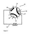
その様な弁の代表的な例は、GE Healthcare社から販売されているINV−907弁である。この弁の概略図を図1から図3に提供している。弁20は、(ポンプの様な)液体供給源に接続するための第1入口1と、(通常は、シリンジ又は専用の試料ポンプを使って)試料を導入するための第2入口2と、(当該技術では周知の)保持毛管ループ(retaining capillary loop)22の様な、流体試料を一時的に保管するための装置へ/からの第3入口3及び第1出口4と、GE Healthcare社から販売されているAKTAexplorerシステムの様な分析又は前処理システムの下流部分に弁を接続する第2出口5と、を有している。更に、弁は、流体が弁を出て直接廃棄口に入るようにする2つの廃棄出口6、7を有している。 A typical example of such a valve is the INV-907 valve sold by GE Healthcare. A schematic of this valve is provided in FIGS. The
INV−907の内側固定子面のオリフィスは、図2の円23の様に、図1から図3には円で示されている。更に、内側固定子面には溝24が設けられている。
図面では、回転子は、その溝25、26、27によって表されている。回転子を回転させると、溝は、内側固定子面に対する位置を変えるので、弁を通る新しい流路ができる。The orifice of the inner stator surface of INV-907 is shown as a circle in FIGS. 1 to 3, as in
In the drawing, the rotor is represented by its
図1は、試料を、一時的な保管のために回転子溝25を介して毛管ループ22に導入する「装填位置」を示している。同時に、ポンプは、回転子溝27を介して残りのシステムを通る流れを提供することができる。この位置では、固定子溝24は、小さな袋小路を形成している。 FIG. 1 shows a “loading position” where the sample is introduced into the
図2は、「注入位置」を示しており、弁が45°回されて、毛管ループ22がシステムの全体流路の一部を形成するようになっている。ポンプは、固定子溝24と回転子溝27及び25を介して、試料を毛管ループから出して、システムに設けられている分離、検出又は他の機能用のシステムに入れる。この位置で、溝27の一部分は、小さな袋小路を形成している。 FIG. 2 shows the “injection position” where the valve is turned 45 ° so that the
図3は、ポンプが、回転子溝27を介して流体を廃棄口へ直接送ることができる「廃棄位置」を示している。
先に述べた様に、試料は、シリンジ又は専用の試料ポンプの何れかを使って導入される。例えば図示の型式の様な従来型の注入弁を使用するには、試料ポンプはシリンジの代わりに用いられるポートに接続しなければならず、即ち、両代替案を同時に使用することはできない。FIG. 3 shows a “discard position” where the pump can send fluid directly to the waste outlet via the
As stated above, the sample is introduced using either a syringe or a dedicated sample pump. For example, to use a conventional infusion valve, such as the type shown, the sample pump must be connected to a port that is used instead of a syringe, i.e., both alternatives cannot be used simultaneously.
従って、ユーザーは、これらの作動モードの間で変更を行うには、システムの配管をやり直さなければならず、システムの柔軟性が減ずることになる。 Thus, to change between these modes of operation, the user must redo the system piping, reducing the flexibility of the system.
本発明の目的は、ユーザーにとってより柔軟性のある試料注入弁を提供することである。
これは、本出願の請求項1による回転弁で達成される。It is an object of the present invention to provide a sample injection valve that is more flexible for the user.
This is achieved with a rotary valve according to
これにより、手動(例えば、シリンジを使用して)又は自動(例えば、専用の試料ポンプを使用して)の両方で、試料を加えることのできる試料注入弁が達成される。 This achieves a sample injection valve that allows the sample to be added both manually (eg, using a syringe) or automatically (eg, using a dedicated sample pump).
代表的な回転弁10の主要部品を、図4に概略的に示している(ブラケット又は同様の荷重担持又は締結要素は図示せず)。回転弁10は、固定子11と、回転子12と、自体の角度位置を認識するための手段(図示せず)を随意的に設けることができる回転軸13と、通常はギアボックスとモーター(弁を手動で作動させることもできるが)を備えている駆動ユニット14と、を有している。回転子は、固定子に対して、弁の回転軸RA周りに回転させることができる。 The main parts of a typical
組み込まれている器具に対して固定される固定子11には、流体源、及び弁が協働する全ての構成要素と流体連通するためのポート(図4には図示せず)が設けられている。ポートは、固定子の外側面の何れの適した位置にでも配置することができる。ポートには、毛管又は配管に接続する手段が設けられている。その様な手段は、当業者には周知の、従来型Valco継手の様な、どの様な適した型式であってもよい。ポートは、内側固定子面11a、即ち、作動中は回転子12と接触している固定子11の表面、の上の対応するオリフィスのセットと、チャネルを介して流体連通している。 The
回転子12は、通常、円盤として形成されており、作動中に、内側固定子面11aに押し付けられる面である内側回転子面12aを有している。内側回転子面12aには、1つ又は複数の溝が設けられており、同溝は、固定子11に対する回転子12の回転位置に依り、内側固定子面11aの異なるオリフィスと相互接続する。 The
図5は、本発明の一実施形態による固定子11の前面の単純化した斜視図を示す。前面は、ここでは、固定子11の、内側固定子面11aとは反対側の面である。入口および出口31a−38aが示されている。 FIG. 5 shows a simplified perspective view of the front surface of the
一般的に、ポートの角度位置、溝、及び本出願の図面に示されている同様のものは、本発明の異なる実施形態の間で異なる場合もあり、即ち、それらは、相互の協働が本発明の概念に従っている限り、弁の回転軸に対して回転させ、鏡像化し、又は別の方法で修正できることに留意頂きたい。 In general, the angular position of the ports, the grooves, and the like shown in the drawings of this application may differ between different embodiments of the present invention, i.e., they cooperate with each other. It should be noted that as long as the inventive concept is followed, it can be rotated, mirrored, or otherwise modified with respect to the axis of rotation of the valve.
更に、固定子の入口/出口ポートは、穴(又はあらゆる型式のチャネル)を介して、内側固定子面11a上のオリフィスに接続されているので、ポートとオリフィスの間に非線形チャネルを作ることにより、ポートを、内側固定子面11a上のオリフィスのパターンとは異なる様式に配置することもできる。固定子へのポートは、固定子の、前側以外の外側面に配置することもできる。しかしながら、単純化のために、図6に関連して後で説明する様に、図では、ポートは、内側固定子面のオリフィスと一直線になるように配置されている。 In addition, the stator inlet / outlet port is connected to the orifice on the
従って、本発明の1つの実施形態による固定子11は、8つのポート31a−38aを有しており、これらのポートを使って、弁は、器具の全ての所望の作動構成要素に接続される。本発明の他の実施形態によれば、幾つかの追加の機構を弁に与えるために、1つ又は複数の追加のオリフィス及びポートを設けることができる。 Thus, the
ポート31aは、第1入口ポート31aと呼ばれている。それは、基本的に固定子の中央に配置されており、器具の主液体供給源、例えば、ここではシステムポンプと呼ばれているポンプからの入口ポートとして使用されている。液体クロマトグラフィーシステムLCSの場合、システムポンプは、単一の、所謂緩衝液、又は、代わりに2つ又はそれ以上の緩衝液の一定の又は可変の混合物の流れを提供する。ポート34aは、第1出口ポート34aと呼ばれ、出口ポートとして機能し、そこから、液体は、器具の残りの部分へと出ることができるようになっている。 The
LCSで使用するための従来型の毛管ループの様な保持ループは、この実施形態では、一端が、第1接続ポート32aに接続されており、他端が、第2接続ポート35aに接続されている。 In this embodiment, a holding loop such as a conventional capillary loop for use in LCS has one end connected to the
ここでは第2及び第3の入口ポート36a、37bと呼ばれている2つのポート36a、37aは、試料を導入するために設けられている。図示の好適な実施形態では、第3入口ポート37aは、通常はシリンジを使用して手動で試料注入するためのものであり、第2入口ポート36aは、専用の試料ポンプに接続するためのものである。試料ポンプは、器具に一体化されていてもよいし、独立した装置であってもよい。 Two
ポート33a及び38aは、第2及び第3の出口ポート33a、38aと呼ばれ、この実施形態では、廃棄出口ポートである。
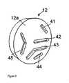
図6は、図5の固定子11を、他の側、即ち、内側固定子面側11aから見た斜視図である。各ポートは、図示のオリフィス32b−38bで終結しているチャネルを介して、内側固定子面11aに接続されていることに注目されたい。単純化するため、32bのオリフィスは、参照番号32aのポートに接続されており、以下同様である。
FIG. 6 is a perspective view of the
オリフィスがポートに接続されているだけでなく、この図示の実施形態では、固定子溝39が、内側固定子面11aに設けられている。固定子溝39は、通常、オリフィスの直径と同じ幅である。なお、システムのポンプが、試料ポンプがループを満たしている間にシステムを通して液体を汲み上げることができるようにするには、固定子溝39が好ましいが(これについては以下に詳しく説明する)、それは本発明の概念に不可欠なものではないことに留意されたい。固定子溝39が無ければ、システムのポンプは、試料ポンプがループを満たしたときに静止しているか、又は、固定子に追加の廃棄出口を設けなくてはならない。例えば、別の廃棄出口を、第2接続オリフィス35bと第2入口オリフィス36bの間に設けてもよい。 Not only is the orifice connected to the port, but in the illustrated embodiment, a
内側固定子面11aを見ると、本発明の1つの実施形態のオリフィスと溝39の端部の全体的角度分布が、図7に示されている。オリフィスと溝端部の位置(及び使用されない位置)は、図では、固定子の中心の周りに等しく分布している(その中心は、弁の回転軸と一致している)。先に述べた様に、オリフィスの位置は、本発明の概念から逸脱することなく、僅かに変えることができる。この実施形態によれば、固定子には12個のその様な位置があるので、分割角度αは、この実施形態では30°である。これら全ての位置は、弁の回転軸から基本的に同じ半径方向距離Rに配置されている。 Looking at the
本発明による弁の実施形態の回転子12の内側回転子面11aを、図8に示している。第1、第2、第3、第4及び第5の溝41−45と呼ばれる5つの溝が設けられている。図9に、溝の相互の位置及び形状を、より明白に示している。 The
各溝は、その両端が、内側回転子面12aの中心(弁の回転軸と一致している)で終結している溝42の一端を除いて、中心から基本的に同じ半径方向距離Rで終結している。勿論、回転子の半径方向距離Rは、固定子の対応する半径方向距離Rと同じである。第1溝41は、本実施形態では30°である角度αに亘って伸張している。第2溝42は、内側回転子面12aの中心から周縁に向いた、長さRを有する真っ直ぐな溝であり、第1溝41の最も近い端部から角度αだけ離れている。第3溝43は、第2溝42から角度αだけ離れた位置で始まり、開始位置から角度3αだけ離れた位置で終結している。それは、中心に向けて内向きに曲り、膝部48(或いは弓形)を形成している。角度αを占める第4溝44は、溝43の両端部の間に等間隔を開けて配置されている。第5溝45は、第3溝43と同様の形状を有している(中心に向けて内向きに変形している膝部47を備えている)が、両端部は、角度2αだけ離れており、第3溝43の最も近い端部から角度αのところで始まっている。 Each groove has essentially the same radial distance R from the center except for one end of the
組み立てられるとき、内側回転子面12aは、何れの従来型回転弁でも一般的な方式(当業者には周知であり、ここでは説明しない)で、内側固定子面11aに押し付けられる。回転子12と固定子11の相互の角度位置に依って、弁では、異なる作動モードが得られる。これらを、図10から図13に示しており、回転子の溝を太線で示している。 When assembled, the
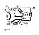
図10に示している第1回転子位置では、弁は、2つの別々流路が使用可能になる。
通常は、LCSのシステムポンプの様なポンプから、勿論、第1入口ポート31aを通って第1入口オリフィス31bに入ってくる流体は、第2溝42を介して弁を通過し、第1出口オリフィス34bから出て、更に、第1出口ポート34aを通って出て行くことができるようになっている。LCSの場合、第1出口ポート34aは、器具の主作動構成要素、例えば、クロマトグラフィーカラムや、UVモニターの様なモニタリング装置に接続するためのものである。図10から図13では、溝とオリフィスを図示し、それについて述べているが、先に述べたオリフィスのそれぞれが、上記の対応するポートに接続されているものと理解されたい。In the first rotor position shown in FIG. 10, the valve allows two separate flow paths.
Normally, the fluid entering the
同時に、試料を第3入口ポート37aに導入することにより、それを毛管ループ50(又は対応する機能を備えた何れかの装置)内に一時的に保管することができる。これは、通常、シリンジを使って行われる。試料は、第3入口ポート37aに入り、第3入口オリフィス37bを通った後で、第3溝43を通って、第2接続オリフィス35b及びポート35aを介してループ50に入る。ループ50は、第2接続ポート35aに接続されており、その他方の端部が第1接続ポート32aに接続されている。これにより、ループ内の流体は、第1溝41と第2出口オリフィス33b及びポート33aを介して廃棄口を出ることができるようになっている。 At the same time, by introducing the sample into the
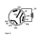
弁のこの他のオリフィス、ポート、及び溝は、第1回転子位置では活動しない。図11に示されている第2回転子位置は、回転子を、第1回転子位置に対して(図10から見て)反時計回りに角度2xαだけ回転させることにより得られ、2つの別々の流路が使用可能になる。 The other orifices, ports, and grooves of the valve are not active in the first rotor position. The second rotor position shown in FIG. 11 is obtained by rotating the rotor counterclockwise (as viewed from FIG. 10) by an
第1入口ポート31a及びオリフィス31bを通って入る流体は、第2溝42を介して弁を通過し、第1接続オリフィス及びポート32b、32aを介してループ50に入る。すると、ループの内容物は、第2接続ポート35a及びオリフィス35bと、第4溝44と、第1出口オリフィス34b及びポート34aとを介して器具の主作動構成要素に押し込まれる。試料は、試料が装填されたのと逆の、ループ50を通る流れの方向を利用して追い出され、従って、試料は、試料の希釈を最小に減じるので有用な、できるだけ短い行程を移動できるようになることに注目頂きたい。 Fluid entering through the
同時に、第2入口ポート36aに接続されている専用の試料ポンプからの流れは、第5溝45と、第3出口オリフィス38b及びポート38aとを介して廃棄口へ送られる。これは、試料ポンプの配管、並びに第5溝45を洗浄するのに有用である。 At the same time, the flow from the dedicated sample pump connected to the
弁の他のポート及び溝は、第2回転子位置では活動しない。
図12に示している様に、第3回転子位置は、回転子を、第1回転子位置に対して(図10から見て)反時計回りに角度4xα回すことにより得られる。第1及び第2位置に対して、第3回転子位置は、弁を通る2つの別々の流路が使用可能になる。The other ports and grooves of the valve are not active in the second rotor position.
As shown in FIG. 12, the third rotor position is obtained by turning the rotor counterclockwise by an angle 4 × α (as viewed from FIG. 10) with respect to the first rotor position. For the first and second positions, the third rotor position allows two separate flow paths through the valve.
第1入口ポート31aとオリフィス31bを通って入る流体は、上記の様に、第2回転子溝42、固定子溝39、第3回転子溝43を介して弁を通過し、第1出口オリフィス34bとポート34aを介して弁を出て、器具の主作動構成要素に入る。これにより、流れを器具の主作動構成要素に提供することができるのと同時に、これらの溝が洗浄されるようになっている。しかしながら、先に述べた様に、溝39を、第2溝42の端部位置にあるか又は終端であってもそこにある廃棄出口に換えることができる。しかしながら、これらの場合、システムの主作動構成要素を通る流れを利用することはできない。 As described above, the fluid entering through the
同時に、試料を第2入口ポート36aとオリフィス36bを通して導入することにより、それを毛管ループ50内に一時的に保管することができる。これは、液体クロマトグラフィーの技術では周知である様に、専用の試料ポンプを使って行われるのが望ましい。試料は、第2入口オリフィス36bに入った後、第5溝45を通って、第2接続オリフィス35bとポート35aを介してループ50に入る。ループ50は、他方の端部が、第1接続ポート32aに接続されているので、ループ内の流体は、第1接続オリフィス32b、第4溝44、第2出口オリフィス33b、及びポート33aを介して廃棄口へ出ることができるようになっている。 At the same time, the sample can be temporarily stored in the
弁のこの他のポート、オリフィス、及び溝は、第3回転子位置では活動していない。
先に述べた様に、ループ50を空にするのは、第2回転子位置を使って行われる。
この上記実施形態では、図13に示している第4回転子位置も有用であるが、本発明の弁を使用するのに必ずしも必要ではない。第4回転子位置は、回転子を、(図10から見て)第1回転子位置に対して反時計回りに角度α回すことにより得られる。The other ports, orifices, and grooves of the valve are not active at the third rotor position.
As described above, emptying the
In this embodiment, the fourth rotor position shown in FIG. 13 is also useful, but is not necessary to use the valve of the present invention. The fourth rotor position is obtained by turning the rotor an angle α counterclockwise with respect to the first rotor position (as viewed from FIG. 10).
第4回転子位置では、第1入口ポート31aとオリフィス31bを通って入る流体は、第2回転子溝42、第2出口オリフィス33b、及びポート33aを介して廃棄出口に直接流れる。この位置は、何らの流体も器具の主作動構成要素を通して弁の下流に送ること無く器具の主ポンプを作動させたいときに用いられる。 In the fourth rotor position, the fluid entering through the
先に述べた様に、オリフィスの正確な位置は、上に述べた実施形態に従う必要はない。本発明にとって重要なのは、異なる溝が、上記の各回転位置にあるときに当然到達するはずの特定のオリフィスに到達することである。 As stated above, the exact location of the orifice need not follow the embodiment described above. What is important for the present invention is that the different grooves reach the specific orifice that should naturally be reached when in each of the above rotational positions.
11 固定子
11a 内側固定子面側
12 回転子
12a 内側回転子面
31a−38a ポート
32b−38b オリフィス
39、41−45 溝
48 溝の屈曲部
50 毛管ループDESCRIPTION OF
Claims (3)
Translated fromJapanese前記内側固定子面(11a)は、
前記固定子への第1入口ポート(31a)と連通している第1入口オリフィス(31b)であって、前記第1入口オリフィス(31b)は、前記内側固定子面(11a)内の基本的に中心に配置され、前記中心は、前記弁の前記回転軸(RA)と基本的に一致している、第1入口オリフィス(31b)と、
前記固定子への第2入口ポート(36a)と連通している第2入口オリフィス(36b)と、
前記固定子への第3入口ポート(37a)と連通している第3入口オリフィス(37b)と、
前記固定子の第1出口ポート(34a)と連通している第1出口オリフィス(34b)と、
前記固定子の第2出口ポート(33a)と連通している第2出口オリフィス(33b)と、
前記固定子の第3出口ポート(38a)と連通している第3出口オリフィス(38b)と、
前記固定子の第1接続ポート(32a)と連通している第1接続オリフィス(32b)と、
前記固定子の第2接続ポート(35a)と連通している第2接続オリフィス(35b)と、を備えており、第1接続ポート(32a)と第2接続ポート(35a)はループ(50)を介して接続されており、
前記第2及び第3入口オリフィス(36b、37b)と、前記第1、第2、及び第3出口オリフィス(34b、33b、38b)と、前記第1及び第2接続オリフィス(32b、35b)は、実質的に、前記内側固定子面(11a)の中心の周りの円上に分布されており、前記円は半径(R)を有しており、更に、
前記内側回転子面(12a)は、第1溝(41)、第2溝(42)、第3溝(43)、第4溝(44)、及び第5溝(45)を備えており、
前記回転子の第1回転位置では、
前記第1溝(41)が、前記第1接続オリフィス(32b)を前記第2出口オリフィス(33b)に接続し、
前記第2溝(42)が、前記第1入口オリフィス(31b)を前記第1出口オリフィス(34b)に接続し、
前記第3溝(43)が、前記第2接続オリフィス(35b)を前記第3入口オリフィス(37b)に接続し、
前記回転子の第2回転位置では、
前記第2溝(42)が、前記第1入口オリフィス(31b)を前記第1接続オリフィス(32b)に接続し、
前記第4溝(44)が、前記第1出口オリフィス(34b)を前記第2接続オリフィス(35b)に接続し、
前記第5溝(45)が、前記第2入口オリフィス(36b)を前記第3出口オリフィス(38b)に接続し、
前記回転子の第3回転位置では、
前記第4溝(44)が、前記第2出口オリフィス(33b)を前記第1接続オリフィス(32b)に接続し、
前記第5溝(45)が、前記第2入口オリフィス(36b)を前記第2接続オリフィス(35b)に接続することを特徴とする、回転弁。A rotary valve (10) having a stator (11) and a rotor (12) adapted to inject a fluid sample into a flow path, wherein the stator (11) There are a number of connection ports that protrude into the interior and each terminate with an orifice on the inner stator surface (11a), the inner stator surface being fluid-tight and said rotor (12 ) Of the stator in contact with the inner rotor surface (12a), the inner rotor surface (12a) of the rotation axis (RA) with respect to the inner stator surface (11a). In a rotary valve that can be rotated around and moved,
The inner stator surface (11a)
A first inlet orifice (31b) in communication with a first inlet port (31a) to the stator, the first inlet orifice (31b) being a basic in the inner stator face (11a); A first inlet orifice (31b), which is centrally located, said center being essentially coincident with said axis of rotation (RA) of said valve;
A second inlet orifice (36b) in communication with a second inlet port (36a) to the stator;
A third inlet orifice (37b) in communication with a third inlet port (37a) to the stator;
A first outlet orifice (34b) in communication with the first outlet port (34a) of the stator;
A second outlet orifice (33b) in communication with the second outlet port (33a) of the stator;
A third outlet orifice (38b) in communication with the third outlet port (38a) of the stator;
A first connection orifice (32b) in communication with the first connection port (32a) of the stator;
A second connection orifice (35b) communicating with the second connection port (35a) of the stator, the first connection port (32a) and the second connection port (35a) being a loop (50). Connected through
The second and third inlet orifices (36b, 37b), the first, second and third outlet orifices (34b, 33b, 38b), and the first and second connection orifices (32b, 35b) are Substantially distributed over a circle around the center of the inner stator face (11a), the circle having a radius (R);
The inner rotor surface (12a) includes a first groove (41), a second groove (42), a third groove (43), a fourth groove (44), and a fifth groove (45),
In the first rotational position of the rotor,
The first groove (41) connects the first connection orifice (32b) to the second outlet orifice (33b);
The second groove (42) connects the first inlet orifice (31b) to the first outlet orifice (34b);
The third groove (43) connects the second connection orifice (35b) to the third inlet orifice (37b);
In the second rotational position of the rotor,
The second groove (42) connects the first inlet orifice (31b) to the first connection orifice (32b);
The fourth groove (44) connects the first outlet orifice (34b) to the second connection orifice (35b);
The fifth groove (45) connects the second inlet orifice (36b) to the third outlet orifice (38b);
In the third rotational position of the rotor,
The fourth groove (44) connects the second outlet orifice (33b) to the first connection orifice (32b);
The rotary valve, wherein the fifth groove (45) connects the second inlet orifice (36b) to the second connection orifice (35b).
前記第2溝(42)が、前記第1入口オリフィス(31b)を前記固定子溝(39)に接続し、
前記第3溝(43)が、前記第1出口オリフィス(34b)を前記固定子溝(39)に接続するように配置されている、請求項1に記載の回転弁。The stator further includes a stator groove (39), and the stator groove (39) has both end portions arranged at a substantially radial distance R from the center of the inner stator surface. And the rotor groove is further in the third rotational position of the rotor,
The second groove (42) connects the first inlet orifice (31b) to the stator groove (39);
The rotary valve according to claim 1, wherein the third groove (43) is arranged to connect the first outlet orifice (34b) to the stator groove (39).
Applications Claiming Priority (3)
| Application Number | Priority Date | Filing Date | Title |
|---|---|---|---|
| SE0700462 | 2007-02-22 | ||
| SE0700462-5 | 2007-02-22 | ||
| PCT/SE2008/000111WO2008103098A1 (en) | 2007-02-22 | 2008-02-11 | Rotation valve for sample injection |
Related Child Applications (1)
| Application Number | Title | Priority Date | Filing Date |
|---|---|---|---|
| JP2013098993ADivisionJP2013178268A (en) | 2007-02-22 | 2013-05-09 | Rotary valve for sample injection |
Publications (2)
| Publication Number | Publication Date |
|---|---|
| JP2010519535A JP2010519535A (en) | 2010-06-03 |
| JP5270582B2true JP5270582B2 (en) | 2013-08-21 |
Family
ID=39710298
Family Applications (2)
| Application Number | Title | Priority Date | Filing Date |
|---|---|---|---|
| JP2009550835AActiveJP5270582B2 (en) | 2007-02-22 | 2008-02-11 | Rotating valve for sample injection |
| JP2013098993APendingJP2013178268A (en) | 2007-02-22 | 2013-05-09 | Rotary valve for sample injection |
Family Applications After (1)
| Application Number | Title | Priority Date | Filing Date |
|---|---|---|---|
| JP2013098993APendingJP2013178268A (en) | 2007-02-22 | 2013-05-09 | Rotary valve for sample injection |
Country Status (8)
| Country | Link |
|---|---|
| US (1) | US8186382B2 (en) |
| EP (1) | EP2113081B1 (en) |
| JP (2) | JP5270582B2 (en) |
| CN (1) | CN101617226B (en) |
| AU (1) | AU2008217771B2 (en) |
| CA (1) | CA2676171C (en) |
| DE (1) | DE202008018594U1 (en) |
| WO (1) | WO2008103098A1 (en) |
Families Citing this family (30)
| Publication number | Priority date | Publication date | Assignee | Title |
|---|---|---|---|---|
| DE102008006266B4 (en) | 2008-01-25 | 2011-06-09 | Dionex Softron Gmbh | Sampler for liquid chromatography, in particular for high performance liquid chromatography |
| WO2010056189A1 (en)* | 2008-11-13 | 2010-05-20 | Ge Healthcare Bio-Sciences Ab | Random access rotary valve |
| AU2009325054A1 (en)* | 2008-12-10 | 2011-07-07 | Alltech Associates Inc. | Automated sample injection apparatus, multiport valve, and methods of making and using the same |
| AU2009347432B2 (en) | 2009-06-03 | 2015-01-29 | Agilent Technologies, Inc. | Sample injector with metering device balancing pressure differences in an intermediate valve state |
| JP5763644B2 (en)* | 2010-06-25 | 2015-08-12 | コリア ユニバーシティ リサーチ アンド ビジネス ファウンデーションKorea University Research And Business Foundation | Multifunctional selector, multifunctional fully automatic liquid chromatography apparatus including the same, and sample analysis method using the same |
| JP5646902B2 (en)* | 2010-07-26 | 2014-12-24 | アークレイ株式会社 | Liquid chromatography device and injection valve |
| JP5639914B2 (en)* | 2011-02-02 | 2014-12-10 | ジーエルサイエンス株式会社 | Switching valve |
| US9304518B2 (en) | 2011-08-24 | 2016-04-05 | Bio-Rad Laboratories, Inc. | Modular automated chromatography system |
| US8960231B2 (en)* | 2011-09-21 | 2015-02-24 | Neil Robert Picha | Multi-mode injection valve |
| US9182886B2 (en) | 2011-11-14 | 2015-11-10 | Bio-Rad Laboratories Inc. | Chromatography configuration interface |
| CN104956199B (en)* | 2013-01-16 | 2018-08-21 | 万科仪器有限合伙公司 | Pump and introduction valve for liquid chromatography |
| US9841406B2 (en) | 2013-04-22 | 2017-12-12 | Sekisui Medical Co., Ltd. | Switching valve for flow type analysis apparatus |
| US9739383B2 (en)* | 2014-07-29 | 2017-08-22 | Idex Health & Science Llc | Multi-path selector valve |
| CN104482249B (en)* | 2014-11-19 | 2017-01-11 | 苏州福润机械有限公司 | Light vacuum rotary valve based on large-caliber joints |
| CN104500784B (en)* | 2015-01-14 | 2017-02-01 | 上海浦东汉威阀门有限公司 | 24-way rotary valve |
| CN104676047B (en)* | 2015-02-16 | 2017-01-11 | 苏州赛谱仪器有限公司 | Injection valve |
| GB201505421D0 (en)* | 2015-03-30 | 2015-05-13 | Ge Healthcare Bio Sciences Ab | A rotary valve and a chromatography system |
| DE202016100451U1 (en) | 2015-06-25 | 2016-02-16 | Dionex Softron Gmbh | Sampler for liquid chromatography, in particular for high performance liquid chromatography |
| CN205064928U (en)* | 2015-09-25 | 2016-03-02 | 厦门建霖工业有限公司 | Central authorities' water purifier control valve |
| CN105927758B (en)* | 2016-06-17 | 2018-04-13 | 厦门百霖净水科技有限公司 | Water softening device control valve and its control method |
| DE102016121516B4 (en)* | 2016-11-10 | 2019-03-28 | Dionex Softron Gmbh | Method and apparatus for sample loading |
| US10527192B2 (en) | 2018-02-15 | 2020-01-07 | Talis Biomedical Corporation | Rotary valve |
| US11680955B2 (en)* | 2018-04-04 | 2023-06-20 | Total Synthesis Ltd. | Fluid diverting module |
| US11008627B2 (en) | 2019-08-15 | 2021-05-18 | Talis Biomedical Corporation | Diagnostic system |
| CN110864138B (en)* | 2019-11-26 | 2021-10-26 | 北京华创精科生物技术有限公司 | Switching valve |
| CN110927299A (en)* | 2019-11-26 | 2020-03-27 | 北京华创精科生物技术有限公司 | Sample injection valve |
| CN112797192B (en)* | 2021-02-03 | 2025-04-04 | 苏州赛谱仪器有限公司 | Liquid delivery valve, mobile phase loading device and liquid delivery control method thereof |
| CN114518426B (en)* | 2022-03-03 | 2023-11-03 | 宁波艾纯生物科技有限公司 | Sample injection valve |
| EP4626538A1 (en)* | 2022-11-28 | 2025-10-08 | Northstar Medical Technologies, Llc | Clean rinsing reversing bypass rotary valve |
| CN116575542B (en)* | 2023-07-13 | 2023-10-03 | 杭州老板电器股份有限公司 | Distribution assembly and integrated sink |
Family Cites Families (15)
| Publication number | Priority date | Publication date | Assignee | Title |
|---|---|---|---|---|
| GB1189995A (en)* | 1966-08-09 | 1970-04-29 | Bp Chem Int Ltd | Gas Chromatography Apparatus |
| US3868970A (en)* | 1973-06-04 | 1975-03-04 | Phillips Petroleum Co | Multipositional selector valve |
| US4068528A (en)* | 1976-01-19 | 1978-01-17 | Rheodyne Incorporated | Two position rotary valve for injecting sample liquids into an analysis system |
| US4158630A (en)* | 1978-02-24 | 1979-06-19 | Stearns Stanley D | Chromatographic multi-sample valving apparatus |
| JPS58134286A (en)* | 1982-02-04 | 1983-08-10 | Toray Ind Inc | rotary valve |
| SE441118B (en)* | 1982-04-07 | 1985-09-09 | Scanpump Ab | throttle |
| US4625569A (en)* | 1984-01-17 | 1986-12-02 | Toyo Soda Manufacturing Co., Ltd. | Liquid injection device |
| JPS61134668A (en)* | 1984-12-06 | 1986-06-21 | Toyo Soda Mfg Co Ltd | liquid injection device |
| US5010921A (en)* | 1989-07-17 | 1991-04-30 | Spectra-Physics, Inc. | Nonsymmetrical valve |
| US5623965A (en)* | 1995-10-30 | 1997-04-29 | Delco Electronics Corporation | Low effort vacuum valve assembly with rotary actuator |
| JPH09243624A (en)* | 1996-03-05 | 1997-09-19 | Shimadzu Corp | Sample introduction device |
| US6155123A (en)* | 1998-04-17 | 2000-12-05 | Rheodyne, L.P. | Multivalving sample injection system |
| US6012488A (en)* | 1998-09-17 | 2000-01-11 | Rheodyne, L.P. | Segmenting valve |
| US6672336B2 (en)* | 2001-11-28 | 2004-01-06 | Rheodyne, Lp | Dual random access, three-way rotary valve apparatus |
| CN1536359A (en)* | 2003-04-10 | 2004-10-13 | 中国科学院大连化学物理研究所 | A method and device for directly injecting gas chromatographic high-temperature and high-pressure samples |
- 2008
- 2008-02-11DEDE202008018594.7Upatent/DE202008018594U1/ennot_activeExpired - Lifetime
- 2008-02-11WOPCT/SE2008/000111patent/WO2008103098A1/enactiveApplication Filing
- 2008-02-11USUS12/523,356patent/US8186382B2/enactiveActive
- 2008-02-11CNCN2008800055806Apatent/CN101617226B/enactiveActive
- 2008-02-11JPJP2009550835Apatent/JP5270582B2/enactiveActive
- 2008-02-11AUAU2008217771Apatent/AU2008217771B2/ennot_activeCeased
- 2008-02-11EPEP08705271.8Apatent/EP2113081B1/enactiveActive
- 2008-02-11CACA2676171Apatent/CA2676171C/enactiveActive
- 2013
- 2013-05-09JPJP2013098993Apatent/JP2013178268A/enactivePending
Also Published As
| Publication number | Publication date |
|---|---|
| CN101617226B (en) | 2012-07-04 |
| EP2113081A1 (en) | 2009-11-04 |
| CA2676171C (en) | 2015-10-20 |
| EP2113081A4 (en) | 2010-08-25 |
| JP2010519535A (en) | 2010-06-03 |
| US8186382B2 (en) | 2012-05-29 |
| CA2676171A1 (en) | 2008-08-24 |
| US20100032604A1 (en) | 2010-02-11 |
| JP2013178268A (en) | 2013-09-09 |
| AU2008217771B2 (en) | 2013-09-26 |
| CN101617226A (en) | 2009-12-30 |
| DE202008018594U1 (en) | 2016-03-29 |
| AU2008217771A1 (en) | 2008-08-28 |
| WO2008103098A1 (en) | 2008-08-28 |
| EP2113081B1 (en) | 2015-11-04 |
Similar Documents
| Publication | Publication Date | Title |
|---|---|---|
| JP5270582B2 (en) | Rotating valve for sample injection | |
| JP5149309B2 (en) | Select valve | |
| JP6348493B2 (en) | General purpose rotary valve | |
| CN101680861B (en) | flow distribution valve | |
| JP5571677B2 (en) | Random access rotary valve | |
| US8286663B2 (en) | Random access rotary valve | |
| JP6651238B2 (en) | Rotary valves and systems | |
| US10113995B2 (en) | Multi-position, micro-fluidic valve assembly with multiple radial grooves to enable individual or combined flows | |
| CN114184723B (en) | Rotary valve, sample loading device and chromatography experiment system |
Legal Events
| Date | Code | Title | Description |
|---|---|---|---|
| A621 | Written request for application examination | Free format text:JAPANESE INTERMEDIATE CODE: A621 Effective date:20110214 | |
| A521 | Request for written amendment filed | Free format text:JAPANESE INTERMEDIATE CODE: A523 Effective date:20120131 | |
| A131 | Notification of reasons for refusal | Free format text:JAPANESE INTERMEDIATE CODE: A131 Effective date:20120625 | |
| A977 | Report on retrieval | Free format text:JAPANESE INTERMEDIATE CODE: A971007 Effective date:20120627 | |
| A601 | Written request for extension of time | Free format text:JAPANESE INTERMEDIATE CODE: A601 Effective date:20120924 | |
| A602 | Written permission of extension of time | Free format text:JAPANESE INTERMEDIATE CODE: A602 Effective date:20121001 | |
| A521 | Request for written amendment filed | Free format text:JAPANESE INTERMEDIATE CODE: A523 Effective date:20121019 | |
| TRDD | Decision of grant or rejection written | ||
| A01 | Written decision to grant a patent or to grant a registration (utility model) | Free format text:JAPANESE INTERMEDIATE CODE: A01 Effective date:20130410 | |
| A61 | First payment of annual fees (during grant procedure) | Free format text:JAPANESE INTERMEDIATE CODE: A61 Effective date:20130509 | |
| R150 | Certificate of patent or registration of utility model | Ref document number:5270582 Country of ref document:JP Free format text:JAPANESE INTERMEDIATE CODE: R150 Free format text:JAPANESE INTERMEDIATE CODE: R150 | |
| R250 | Receipt of annual fees | Free format text:JAPANESE INTERMEDIATE CODE: R250 | |
| R250 | Receipt of annual fees | Free format text:JAPANESE INTERMEDIATE CODE: R250 | |
| R250 | Receipt of annual fees | Free format text:JAPANESE INTERMEDIATE CODE: R250 | |
| R250 | Receipt of annual fees | Free format text:JAPANESE INTERMEDIATE CODE: R250 | |
| R250 | Receipt of annual fees | Free format text:JAPANESE INTERMEDIATE CODE: R250 | |
| S533 | Written request for registration of change of name | Free format text:JAPANESE INTERMEDIATE CODE: R313533 | |
| R371 | Transfer withdrawn | Free format text:JAPANESE INTERMEDIATE CODE: R371 | |
| S531 | Written request for registration of change of domicile | Free format text:JAPANESE INTERMEDIATE CODE: R313531 | |
| S533 | Written request for registration of change of name | Free format text:JAPANESE INTERMEDIATE CODE: R313533 | |
| R350 | Written notification of registration of transfer | Free format text:JAPANESE INTERMEDIATE CODE: R350 | |
| R250 | Receipt of annual fees | Free format text:JAPANESE INTERMEDIATE CODE: R250 | |
| R250 | Receipt of annual fees | Free format text:JAPANESE INTERMEDIATE CODE: R250 | |
| R250 | Receipt of annual fees | Free format text:JAPANESE INTERMEDIATE CODE: R250 | |
| R250 | Receipt of annual fees | Free format text:JAPANESE INTERMEDIATE CODE: R250 | |
| R250 | Receipt of annual fees | Free format text:JAPANESE INTERMEDIATE CODE: R250 |