JP5270263B2 - Substrate processing apparatus and substrate processing method - Google Patents
Substrate processing apparatus and substrate processing methodDownload PDFInfo
- Publication number
- JP5270263B2 JP5270263B2JP2008221863AJP2008221863AJP5270263B2JP 5270263 B2JP5270263 B2JP 5270263B2JP 2008221863 AJP2008221863 AJP 2008221863AJP 2008221863 AJP2008221863 AJP 2008221863AJP 5270263 B2JP5270263 B2JP 5270263B2
- Authority
- JP
- Japan
- Prior art keywords
- substrate
- liquid film
- counter plate
- liquid
- wafer
- Prior art date
- Legal status (The legal status is an assumption and is not a legal conclusion. Google has not performed a legal analysis and makes no representation as to the accuracy of the status listed.)
- Expired - Fee Related
Links
- 239000000758substrateSubstances0.000titleclaimsabstractdescription192
- 238000003672processing methodMethods0.000titleclaimsdescription10
- 239000007788liquidSubstances0.000claimsabstractdescription305
- 230000002093peripheral effectEffects0.000claimsabstractdescription56
- 238000011144upstream manufacturingMethods0.000claimsdescription9
- 238000000034methodMethods0.000claimsdescription8
- 238000007599dischargingMethods0.000claimsdescription2
- 230000007246mechanismEffects0.000abstractdescription54
- 235000012431wafersNutrition0.000description153
- 239000007789gasSubstances0.000description33
- XLYOFNOQVPJJNP-UHFFFAOYSA-NwaterChemical compoundOXLYOFNOQVPJJNP-UHFFFAOYSA-N0.000description28
- 239000008367deionised waterSubstances0.000description26
- 229910021641deionized waterInorganic materials0.000description26
- VYPSYNLAJGMNEJ-UHFFFAOYSA-NSilicium dioxideChemical compoundO=[Si]=OVYPSYNLAJGMNEJ-UHFFFAOYSA-N0.000description14
- 229910052814silicon oxideInorganic materials0.000description13
- 229910052710siliconInorganic materials0.000description7
- 239000010703siliconSubstances0.000description7
- XUIMIQQOPSSXEZ-UHFFFAOYSA-NSiliconChemical compound[Si]XUIMIQQOPSSXEZ-UHFFFAOYSA-N0.000description6
- 239000002344surface layerSubstances0.000description6
- 229920001343polytetrafluoroethylenePolymers0.000description4
- 239000004810polytetrafluoroethyleneSubstances0.000description4
- 239000004065semiconductorSubstances0.000description4
- KRHYYFGTRYWZRS-UHFFFAOYSA-NFluoraneChemical compoundFKRHYYFGTRYWZRS-UHFFFAOYSA-N0.000description3
- -1PolytetrafluoroethylenePolymers0.000description3
- 239000011148porous materialSubstances0.000description3
- 239000004698PolyethyleneSubstances0.000description2
- 239000004372Polyvinyl alcoholSubstances0.000description2
- 238000010521absorption reactionMethods0.000description2
- 230000000694effectsEffects0.000description2
- 238000005530etchingMethods0.000description2
- 239000004973liquid crystal related substanceSubstances0.000description2
- 239000003595mistSubstances0.000description2
- 229920002451polyvinyl alcoholPolymers0.000description2
- IJGRMHOSHXDMSA-UHFFFAOYSA-NAtomic nitrogenChemical compoundN#NIJGRMHOSHXDMSA-UHFFFAOYSA-N0.000description1
- JOYRKODLDBILNP-UHFFFAOYSA-NEthyl urethaneChemical compoundCCOC(N)=OJOYRKODLDBILNP-UHFFFAOYSA-N0.000description1
- BZHJMEDXRYGGRV-UHFFFAOYSA-NVinyl chlorideChemical compoundClC=CBZHJMEDXRYGGRV-UHFFFAOYSA-N0.000description1
- 238000011109contaminationMethods0.000description1
- 229910001873dinitrogenInorganic materials0.000description1
- 239000011521glassSubstances0.000description1
- 229910000040hydrogen fluorideInorganic materials0.000description1
- 230000005661hydrophobic surfaceEffects0.000description1
- 239000011261inert gasSubstances0.000description1
- 238000004519manufacturing processMethods0.000description1
- 239000000463materialSubstances0.000description1
- 230000003287optical effectEffects0.000description1
- 230000001590oxidative effectEffects0.000description1
- 238000005498polishingMethods0.000description1
- 229920000573polyethylenePolymers0.000description1
- 229920000915polyvinyl chloridePolymers0.000description1
- 239000004800polyvinyl chlorideSubstances0.000description1
- 239000010453quartzSubstances0.000description1
- 150000003376siliconChemical class0.000description1
- 239000007787solidSubstances0.000description1
- 238000006467substitution reactionMethods0.000description1
- 230000008961swellingEffects0.000description1
- 238000005406washingMethods0.000description1
Images


Classifications
- H—ELECTRICITY
- H01—ELECTRIC ELEMENTS
- H01L—SEMICONDUCTOR DEVICES NOT COVERED BY CLASS H10
- H01L21/00—Processes or apparatus adapted for the manufacture or treatment of semiconductor or solid state devices or of parts thereof
- H01L21/67—Apparatus specially adapted for handling semiconductor or electric solid state devices during manufacture or treatment thereof; Apparatus specially adapted for handling wafers during manufacture or treatment of semiconductor or electric solid state devices or components ; Apparatus not specifically provided for elsewhere
- H01L21/67005—Apparatus not specifically provided for elsewhere
- H01L21/67011—Apparatus for manufacture or treatment
- H01L21/6715—Apparatus for applying a liquid, a resin, an ink or the like
- H—ELECTRICITY
- H01—ELECTRIC ELEMENTS
- H01L—SEMICONDUCTOR DEVICES NOT COVERED BY CLASS H10
- H01L21/00—Processes or apparatus adapted for the manufacture or treatment of semiconductor or solid state devices or of parts thereof
- H01L21/67—Apparatus specially adapted for handling semiconductor or electric solid state devices during manufacture or treatment thereof; Apparatus specially adapted for handling wafers during manufacture or treatment of semiconductor or electric solid state devices or components ; Apparatus not specifically provided for elsewhere
- H01L21/67005—Apparatus not specifically provided for elsewhere
- H01L21/67011—Apparatus for manufacture or treatment
- H01L21/67017—Apparatus for fluid treatment
- H01L21/67028—Apparatus for fluid treatment for cleaning followed by drying, rinsing, stripping, blasting or the like
- H01L21/6704—Apparatus for fluid treatment for cleaning followed by drying, rinsing, stripping, blasting or the like for wet cleaning or washing
- H01L21/67051—Apparatus for fluid treatment for cleaning followed by drying, rinsing, stripping, blasting or the like for wet cleaning or washing using mainly spraying means, e.g. nozzles
- H—ELECTRICITY
- H01—ELECTRIC ELEMENTS
- H01L—SEMICONDUCTOR DEVICES NOT COVERED BY CLASS H10
- H01L21/00—Processes or apparatus adapted for the manufacture or treatment of semiconductor or solid state devices or of parts thereof
- H01L21/67—Apparatus specially adapted for handling semiconductor or electric solid state devices during manufacture or treatment thereof; Apparatus specially adapted for handling wafers during manufacture or treatment of semiconductor or electric solid state devices or components ; Apparatus not specifically provided for elsewhere
- H01L21/67005—Apparatus not specifically provided for elsewhere
- H01L21/67011—Apparatus for manufacture or treatment
- H01L21/67017—Apparatus for fluid treatment
- H01L21/67063—Apparatus for fluid treatment for etching
- H01L21/67075—Apparatus for fluid treatment for etching for wet etching
- H01L21/6708—Apparatus for fluid treatment for etching for wet etching using mainly spraying means, e.g. nozzles
Landscapes
- Engineering & Computer Science (AREA)
- Physics & Mathematics (AREA)
- Condensed Matter Physics & Semiconductors (AREA)
- General Physics & Mathematics (AREA)
- Manufacturing & Machinery (AREA)
- Computer Hardware Design (AREA)
- Microelectronics & Electronic Packaging (AREA)
- Power Engineering (AREA)
- Cleaning Or Drying Semiconductors (AREA)
- Weting (AREA)
- Exposure Of Semiconductors, Excluding Electron Or Ion Beam Exposure (AREA)
Abstract
Description
Translated fromJapanese本発明は、基板に対する処理液を用いた処理のための基板処理装置および基板処理方法に関する。処理の対象となる基板には、たとえば、半導体ウエハ、液晶表示装置用基板、プラズマディスプレイ用基板、FED(Field Emission Display)用基板、光ディスク用基板、磁気ディスク用基板、光磁気ディスク用基板、フォトマスク用基板などが含まれる。 The present invention relates to a substrate processing apparatus and a substrate processing method for processing using a processing liquid for a substrate. Examples of substrates to be processed include semiconductor wafers, liquid crystal display substrates, plasma display substrates, FED (Field Emission Display) substrates, optical disk substrates, magnetic disk substrates, magneto-optical disk substrates, photo A mask substrate is included.
半導体ウエハや液晶表示パネル用ガラス基板などの基板の大型化に伴って、枚葉式の基板処理装置が用いられてきている。
枚葉式の基板処理装置は、たとえば、基板を水平な姿勢に保持して回転させるスピンチャックと、基板の表面に処理液を供給するためのノズルとを備えている。基板は、その表面(処理対象面)を上方に向けた状態でスピンチャックに保持される。そして、スピンチャックにより基板が回転されつつ、その基板の表面の中央部にノズルから処理液が供給される。基板の表面に供給された処理液は、基板の回転による遠心力を受けて、基板の表面上をその中央部から周縁に向けて流れる。With the increase in size of substrates such as semiconductor wafers and glass substrates for liquid crystal display panels, single-wafer type substrate processing apparatuses have been used.
The single-wafer type substrate processing apparatus includes, for example, a spin chuck that rotates the substrate while holding the substrate in a horizontal posture, and a nozzle for supplying a processing liquid to the surface of the substrate. The substrate is held by the spin chuck with its surface (surface to be processed) facing upward. Then, while the substrate is rotated by the spin chuck, the processing liquid is supplied from the nozzle to the center of the surface of the substrate. The processing liquid supplied to the surface of the substrate receives a centrifugal force due to the rotation of the substrate and flows on the surface of the substrate from the central portion toward the peripheral edge.
半導体装置の製造工程では、枚葉式の基板処理装置を用いて、シリコンからなる半導体ウエハ(以下、単に「ウエハ」という。)の表面からシリコン酸化膜を除去する処理が行われることがある。この場合、処理液には、HF(フッ酸)またはBHF(Buffered Hydrogen Fluoride:バッファードフッ酸)およびDIW(deionized water)が用いられる。ウエハが回転されつつ、ウエハの表面にHFまたはBHFが供給されることにより、ウエハの表面に形成されているシリコン酸化膜が除去される。その後、ウエハの回転が持続された状態で、ウエハの表面にDIWが供給されることにより、ウエハの表面に付着しているHFまたはBHFが洗い流される。このDIWによる水洗後は、DIWがウエハの高速回転によりウエハから振り切られ、ウエハが乾燥すると、シリコン酸化膜を除去するための一連の処理が終了する。
ウエハの表面からシリコン酸化膜が除去されると、そのウエハの表面には、シリコンが露出する。このシリコンの表面は、水素終端化されており、疎水性を示す。そのため、ウエハの表面におけるシリコン酸化膜が除去された部分(シリコンが露出した部分)では、その表面に対する処理液の接触角が大きくなる。その結果、ウエハの表面に処理液で覆われない部分が生じ、その部分に雰囲気中に浮遊する水滴や固形異物が付着することによるウエハの汚染を招くおそれがある。とくに、ウエハの周縁部上では、処理液に作用する遠心力が弱いので、処理液が筋状をなして流れ、処理液で覆われない部分が生じやすい。 When the silicon oxide film is removed from the surface of the wafer, silicon is exposed on the surface of the wafer. The surface of this silicon is hydrogen-terminated and exhibits hydrophobicity. Therefore, the contact angle of the treatment liquid with respect to the surface of the wafer surface where the silicon oxide film is removed (the portion where the silicon is exposed) increases. As a result, a portion that is not covered with the processing liquid is generated on the surface of the wafer, and there is a risk of causing contamination of the wafer due to adhesion of water droplets or solid foreign matters floating in the atmosphere. In particular, since the centrifugal force acting on the processing liquid is weak on the peripheral edge of the wafer, the processing liquid flows in a streak shape, and a portion that is not covered with the processing liquid tends to occur.
ウエハの表面の全域が処理液により確実に覆われるようにするために、ウエハに供給される処理液の流量およびウエハの回転速度を増大させることが考えられるが、その方策では、1枚のウエハの処理に要するコストが増えてしまう。また、ウエハから飛散する処理液がスピンチャックの周囲に配置されている部材に高速で衝突することにより、処理液のミストが多量に発生してしまう。処理液のミストは、処理後のウエハの乾燥状態を悪化させるほか、処理後のウエハの表面に付着することによりウォータマークの発生の原因となる。 In order to ensure that the entire surface of the wafer is covered with the processing liquid, it is conceivable to increase the flow rate of the processing liquid supplied to the wafer and the rotation speed of the wafer. The cost required for this process increases. Further, a large amount of mist of the processing liquid is generated when the processing liquid scattered from the wafer collides with a member disposed around the spin chuck at a high speed. The mist of the processing liquid not only deteriorates the dry state of the processed wafer, but also causes the generation of watermarks by adhering to the surface of the processed wafer.
そこで、本発明の目的は、基板に供給される処理液の流量および基板の回転速度を増大させることなく、基板の表面の全域に処理液をむらなく行き渡らせることができる、基板処理装置および基板処理方法を提供することである。 SUMMARY OF THE INVENTION Accordingly, an object of the present invention is to provide a substrate processing apparatus and a substrate that can uniformly distribute the processing liquid over the entire surface of the substrate without increasing the flow rate of the processing liquid supplied to the substrate and the rotation speed of the substrate. It is to provide a processing method.
前記の目的を達成するための請求項1記載の発明は、基板(W)を水平姿勢に保持し、その基板の中心を通る軸線まわりに回転させる基板回転手段(2)と、前記基板回転手段により回転される基板の上面(表面)の中央部に処理液を供給する処理液供給手段(3)と、前記基板回転手段により回転される基板の上面に対向配置される対向部材(13)と、前記処理液供給手段による処理液の供給と並行して、前記対向部材を基板の中央部に対向する位置から周縁部に対向する位置へと移動させ、その移動によって、当該基板の中央部を覆っている処理液の液膜を基板の周縁に向けて拡張させる液膜拡張手段(14,15,16)とを含み、前記対向部材は、基板の上面と平行な下面(132)を有する略長方形板状をなすと共に、その長手方向が基板の回転半径方向に沿う対向板(13)であり、前記対向板は、その下面から基板の回転方向の上流側に向けて延設され、外側に凸湾曲する湾曲面(133)を有しており、前記液膜拡張手段は、前記対向板の前記下面が前記液膜に接触するように前記対向板を配置し、前記対向板と前記液膜との接触状態を維持しつつ、前記対向板を基板の周縁部に対向する位置に向けて前記長手方向に沿う方向に移動させる、基板処理装置(1)である。In order to achieve the above object, the present invention as claimed in
なお、括弧内の英数字は、後述の実施形態における対応構成要素等を表す。以下、この項において同じ。
この構成によれば、基板回転手段により、基板が水平姿勢に保持された状態でその中心を通る軸線まわりに回転される。この回転中の基板の上面の中央部に、処理液供給手段により処理液が供給される。たとえ基板の上面が疎水性を示していても、処理液供給手段により処理液が供給されている間は、少なくとも基板の上面における処理液の供給位置付近、つまり中央部に処理液の液膜が形成される。その一方で、対向部材が基板の上面の中央部に対向配置される。そして、対向部材が基板の中央部に対向する位置から周縁部に対向する位置へと移動され、その移動によって、基板の中央部を覆っている処理液の液膜が基板の周縁に向けて拡張される。この液膜の拡張のために、処理液供給手段により基板に供給される処理液の流量および基板回転手段による基板の回転速度を増大させる必要はない。In addition, the alphanumeric characters in parentheses represent corresponding components in the embodiments described later. The same applies hereinafter.
According to this configuration, the substrate is rotated around the axis passing through the center of the substrate while being held in a horizontal posture by the substrate rotating means. A processing liquid is supplied to the central portion of the upper surface of the rotating substrate by the processing liquid supply means. Even if the upper surface of the substrate shows hydrophobicity, a liquid film of the processing liquid is at least near the processing liquid supply position on the upper surface of the substrate, that is, in the center while the processing liquid is supplied by the processing liquid supply means. It is formed. On the other hand, the facing member is disposed to face the central portion of the upper surface of the substrate. Then, the counter member is moved from a position facing the central portion of the substrate to a position facing the peripheral portion, and the liquid film of the processing liquid covering the central portion of the substrate is expanded toward the peripheral edge of the substrate by the movement. Is done. In order to expand the liquid film, it is not necessary to increase the flow rate of the processing liquid supplied to the substrate by the processing liquid supply unit and the rotation speed of the substrate by the substrate rotating unit.
よって、供給される処理液の流量および基板の回転速度を増大させることなく、基板の表面の全域に処理液をむらなく行き渡らせることができる。Therefore, the processing liquid can be evenly distributed over the entire surface of the substrate without increasing the flow rate of the supplied processing liquid and the rotation speed of the substrate.
さらに、この構成によれば、対向板の下面が液膜に接触した状態で、対向板が移動されると、液膜(処理液)の表面張力により、液膜を形成している処理液が対向板につられて移動する。基板が回転されているので、対向板が基板の中央部に対向する位置から基板の周縁部に対向する位置に向けて移動されると、対向板の下面と接触している処理液が液膜の周囲に渦を描き、これにより液膜の径が増大していく。その結果、液膜を拡張させることができる。Furthermore, according to this configuration , when the counter plate is moved in a state where the lower surface of the counter plate is in contact with the liquid film, the processing liquid forming the liquid film is caused by the surface tension of the liquid film (processing liquid). Moves on the opposite plate. Since the substrate is rotated, when the counter plate is moved from the position facing the central portion of the substrate toward the position facing the peripheral edge of the substrate, the processing liquid in contact with the lower surface of the counter plate is liquid film. A vortex is drawn around the surface of the film, thereby increasing the diameter of the liquid film. As a result, the liquid film can be expanded.
さらに、この構成によれば、対向板は、基板の回転により、基板の上面の液膜に対してその回転方向の上流側へ移動する。そのため、対向板が湾曲面を有していれば、湾曲面により、液膜を形成している処理液を対向板の下面と基板の上面との間にスムーズに入り込ませることができる。その結果、対向板と処理液との接触状態を良好に維持することができる。
請求項2に記載のように、前記液膜拡張手段は、前記対向板の前記下面が前記液膜に接触する位置まで前記対向板を下降させ、前記対向板の前記下面が前記液膜に接触する高さに前記対向板を維持した状態で、前記対向板が基板の周縁部に対向する位置まで前記対向板を前記長手方向に移動させてもよい。
また、請求項3に記載のように、前記液膜拡張手段は、基板の中央部を覆っている処理液の液膜を基板の周縁に向けて拡張させることにより、基板の上面全域を覆う処理液の液膜を形成してもよい。
また、請求項4に記載のように、前記処理液供給手段は、基板に向けて処理液を吐出するノズル(8)を含み、前記対向部材は、前記ノズルから離れた位置に配置されていてもよい。
また、請求項5に記載のように、前記対向板の前記湾曲面は、基板の回転方向の上流側を向いていてもよい。Further, according to this configuration, the counter plate moves to the upstream side in the rotation direction with respect to the liquid film on the upper surface of the substrate by the rotation of the substrate. Therefore, if the opposing plate has a curved surface, the curved surface allows the processing liquid forming the liquid film to smoothly enter between the lower surface of the opposing plate and the upper surface of the substrate. As a result, the contact state between the counter plate and the treatment liquid can be favorably maintained.
The liquid film expanding means lowers the counter plate to a position where the lower surface of the counter plate contacts the liquid film, and the lower surface of the counter plate contacts the liquid film. The counter plate may be moved in the longitudinal direction to a position where the counter plate opposes the peripheral edge of the substrate while maintaining the counter plate at a height to be maintained.
According to a third aspect of the present invention, the liquid film expanding means extends the liquid film of the processing liquid covering the central portion of the substrate toward the peripheral edge of the substrate, thereby covering the entire upper surface of the substrate. A liquid film of liquid may be formed.
According to a fourth aspect of the present invention, the processing liquid supply means includes a nozzle (8) that discharges the processing liquid toward the substrate, and the opposing member is disposed at a position away from the nozzle. Also good.
According to a fifth aspect of the present invention, the curved surface of the counter plate may face the upstream side in the rotation direction of the substrate.
対向板と処理液との接触状態をさらに良好に維持するため、請求項6に記載のように、前記対向板は、前記液膜と接触する面が親水化処理されていることが好ましい。
また、前記対向部材が前記対向板でない場合、前記対向部材は、多孔質材料からなる多孔質部材(61)であり、前記液膜拡張手段は、前記多孔質部材を前記液膜に接触するように配置し、前記多孔質部材と前記液膜との接触状態を維持しつつ、前記多孔質部材を基板の周縁部に対向する位置に向けて移動させてもよい。In order to maintain the contact state between the counter plate and the treatment liquid more satisfactorily, as described in
When the counter member is not the counter plate, the counter member is a porous member (61) made of a porous material, and the liquid film expanding means contacts the liquid member with the liquid film. The porous member may be moved toward a position facing the peripheral edge of the substrate while maintaining the contact state between the porous member and the liquid film.
多孔質部材が液膜に接触した状態で、多孔質部材が移動されると、多孔質部材の吸液性および液膜(処理液)の表面張力により、液膜を形成している処理液が対向部材につられて移動する。基板が回転されているので、多孔質部材が基板の中央部に対向する位置から基板の周縁部に対向する位置に向けて移動されると、多孔質部材と接触している処理液が液膜の周囲に渦を描き、これにより液膜の径が増大していく。その結果、液膜を拡張させることができる。When the porous member is moved while the porous member is in contact with the liquid film, the processing liquid forming the liquid film is absorbed by the liquid absorption of the porous member and the surface tension of the liquid film (processing liquid). It moves with the opposingmember . Since the substrate is rotated, when the porous member is moved from the position facing the central portion of the substrate toward the position facing the peripheral edge of the substrate, the processing liquid that is in contact with the porous member becomes a liquid film. A vortex is drawn around the surface of the film, thereby increasing the diameter of the liquid film. As a result, the liquid film can be expanded.
また、前記対向部材が前記対向板でない場合、前記対向部材は、スリット状の吐出口(411)を有し、当該吐出口からガスを吐出するガスノズル(41)であり、前記液膜拡張手段は、前記吐出口から吐出されるガスが前記液膜に吹き付けられるように前記ガスノズルを配置し、前記液膜の表層部分がガスにより押し潰された状態を維持しつつ、前記ガスノズルを基板の周縁部に対向する位置に向けて移動させてもよい。When the facing member is not the facing plate, the facing member is a gas nozzle (41) that has a slit-like discharge port (411) and discharges gas from the discharge port. The gas nozzle is arranged so that the gas discharged from the discharge port is blown to the liquid film, and the gas nozzle is moved to the peripheral edge of the substrate while maintaining the surface layer portion of the liquid film being crushed by the gas. You may move toward the position which opposes.
液膜の表層部分がガスノズルからのガスにより押し潰された状態、つまり表面張力により形成される液膜の表面の一部がガスノズルからのガスにより決壊された状態で、ガスノズルが移動されると、その決壊された部分から処理液が基板の周縁に向けて流れる。基板が回転されているので、ガスノズルが基板の中央部に対向する位置から基板の周縁部に対向する位置に向けて移動されると、液膜から流れ出る処理液が液膜の周囲に渦を描き、これにより液膜の径が増大していく。その結果、液膜を拡張させることができる。 When the gas nozzle is moved in a state where the surface layer portion of the liquid film is crushed by the gas from the gas nozzle, that is, a part of the surface of the liquid film formed by the surface tension is broken by the gas from the gas nozzle, From the broken portion, the processing liquid flows toward the periphery of the substrate. Since the substrate is rotated, when the gas nozzle is moved from the position facing the center of the substrate toward the position facing the peripheral edge of the substrate, the processing liquid flowing out of the liquid film draws a vortex around the liquid film. This increases the diameter of the liquid film. As a result, the liquid film can be expanded.
また、前記対向部材が前記対向板でない場合、前記対向部材は、前記処理液供給手段により供給される処理液と同種の処理液を吐出する処理液ノズル(61)であり、前記液膜拡張手段は、前記処理液ノズルから吐出される処理液が前記液膜に吹き付けられるように前記処理液ノズルを配置し、前記液膜の表層部分が前記処理液ノズルからの処理液により押し潰された状態を維持しつつ、前記処理液ノズルを基板の周縁部に対向する位置に向けて移動させてもよい。When the counter member is not the counter plate, the counter member is a processing liquid nozzle (61) that discharges the same type of processing liquid as the processing liquid supplied by the processing liquid supply means, and the liquid film expanding means Is a state in which the processing liquid nozzle is arranged so that the processing liquid discharged from the processing liquid nozzle is sprayed onto the liquid film, and a surface layer portion of the liquid film is crushed by the processing liquid from the processing liquid nozzle The processing solution nozzle may be moved toward a position facing the peripheral edge of the substrate while maintaining the above.
液膜の表層部分が処理液ノズルからの処理液により押し潰された状態、つまり表面張力により形成される液膜の表面の一部が処理液ノズルからの処理液により決壊された状態で、処理液ノズルが移動されると、その決壊された部分から処理液が基板の周縁に向けて流れる。基板が回転されているので、処理液ノズルが基板の中央部に対向する位置から基板の周縁部に対向する位置に向けて移動されると、液膜から流れ出る処理液が液膜の周囲に渦を描き、これにより液膜の径が増大していく。その結果、液膜を拡張させることができる。 Processing in a state where the surface layer portion of the liquid film is crushed by the processing liquid from the processing liquid nozzle, that is, in a state where a part of the surface of the liquid film formed by the surface tension is broken by the processing liquid from the processing liquid nozzle When the liquid nozzle is moved, the processing liquid flows from the broken portion toward the periphery of the substrate. Since the substrate is rotated, when the processing liquid nozzle is moved from the position facing the central portion of the substrate toward the position facing the peripheral edge of the substrate, the processing liquid flowing out of the liquid film is swirled around the liquid film. This will increase the diameter of the liquid film. As a result, the liquid film can be expanded.
請求項7に記載の発明は、基板(W)を水平姿勢でその基板の中心を通る軸線まわりに回転させる基板回転工程と、回転中の基板の上面の中央部に処理液を供給する処理液供給工程と、前記処理液供給工程と並行して、対向部材(13,41,51,61,71)を基板の上面に対向配置し、前記対向部材を基板の中央部に対向する位置から周縁部に対向する位置へと移動させ、その移動によって、当該基板の中央部を覆っている処理液の液膜を基板の周縁に向けて拡張させる液膜拡張工程とを含み、前記対向部材は、基板の上面と平行な下面を有する略長方形板状をなすと共に、その長手方向が基板の回転半径方向に沿う対向板であり、前記対向板は、その下面から基板の回転方向の上流側に向けて延設され、外側に凸湾曲する湾曲面を有しており、前記液膜拡張工程では、前記対向板の前記下面が前記液膜に接触するように前記対向板が配置され、前記対向板と前記液膜との接触状態が維持されつつ、前記対向板が基板の周縁部に対向する位置に向けて前記長手方向に沿う方向に移動される、基板処理方法である。The invention according to
この方法は、請求項1に記載の基板処理装置において実施することができ、この方法の実施により、請求項1に関連して述べた効果と同様な効果を奏することができる。
請求項8に記載のように、前記液膜拡張工程は、前記対向板の前記下面が前記液膜に接触する位置まで前記対向板を下降させ、前記対向板の前記下面が前記液膜に接触する高さに前記対向板を維持した状態で、前記対向板が基板の周縁部に対向する位置まで前記対向板を前記長手方向に移動させてもよい。
また、請求項9に記載のように、前記液膜拡張工程は、基板の中央部を覆っている処理液の液膜を基板の周縁に向けて拡張させることにより、基板の上面全域を覆う処理液の液膜を形成してもよい。
また、請求項10に記載のように、前記処理液供給工程は、ノズルから処理液を吐出させることにより、回転中の基板の上面の中央部に処理液を供給する工程であり、前記対向部材は、前記ノズルから離れた位置に配置されていてもよい。
また、請求項11に記載のように、前記対向板の前記湾曲面は、基板の回転方向の上流側を向いていてもよい。
また、請求項12に記載のように、前記対向板は、前記液膜と接触する面が親水化処理されていてもよい。This method can be performed in the substrate processing apparatus according to the first aspect, and by implementing this method, the same effects as those described in relation to the first aspect can be obtained.
The liquid film expansion step includes lowering the counter plate to a position where the lower surface of the counter plate contacts the liquid film, and the lower surface of the counter plate contacts the liquid film. The counter plate may be moved in the longitudinal direction to a position where the counter plate opposes the peripheral edge of the substrate while maintaining the counter plate at a height to be maintained.
According to a ninth aspect of the present invention, in the liquid film expanding step, the liquid film of the processing liquid covering the central portion of the substrate is expanded toward the peripheral edge of the substrate to cover the entire upper surface of the substrate. A liquid film of liquid may be formed.
The processing liquid supply step is a step of supplying the processing liquid to a central portion of the upper surface of the rotating substrate by discharging the processing liquid from a nozzle, and the counter member May be arranged at a position away from the nozzle.
In addition, as described in
Moreover, as described in
以下では、本発明の実施の形態を、添付図面を参照して詳細に説明する。
図1は、本発明の一実施形態に係る基板処理装置の構成を図解的に示す断面図である。
基板処理装置1は、基板の一例としてのウエハWをほぼ水平な姿勢に保持して回転させるためのウエハ回転機構2と、ウエハ回転機構2に保持されたウエハWの上面(表面)に処理液を供給するための処理液供給機構3とを備えている。Hereinafter, embodiments of the present invention will be described in detail with reference to the accompanying drawings.
FIG. 1 is a cross-sectional view schematically showing a configuration of a substrate processing apparatus according to an embodiment of the present invention.
The
ウエハ回転機構2としては、たとえば、挟持式のものが採用されている。具体的には、ウエハ回転機構2は、モータ4と、このモータ4の駆動軸と一体化されたスピン軸5と、スピン軸5の上端にほぼ水平に取り付けられた円板状のスピンベース6と、スピンベース6の周縁部の複数箇所にほぼ等角度間隔で設けられた複数個の挟持部材7とを備えている。 As the wafer
複数個の挟持部材7により、ウエハWをほぼ水平な姿勢で挟持することができる。この状態で、モータ4が駆動されると、その駆動力によって、そのスピンベース6とともに、ウエハWがほぼ水平な姿勢を保った状態でスピン軸5の中心軸線まわりに回転される。
処理液供給機構3は、ノズル8と、ノズル8に接続された供給管9と、供給管9の途中部に介装されたバルブ10とを備えている。The wafer W can be held in a substantially horizontal posture by the plurality of holding
The processing
ノズル8は、アーム11の先端部に取り付けられている。アーム11は、ウエハ回転機構2の上方で水平に延びている。アーム11には、モータなどを含むノズル移動機構12が結合されている。ノズル移動機構12により、アーム11をウエハ回転機構2の側方に設定された軸線を中心に水平面内で揺動させることができる。アーム11の揺動に伴って、ノズル8は、ウエハ回転機構2の上方で水平移動する。 The
供給管9には、図示しない処理液供給源から処理液が供給される。バルブ10が開かれると、供給管9に供給される処理液が供給管9からノズル8に供給され、ノズル8から下方に向けて処理液が吐出される。
また、ウエハ回転機構2の上方には、対向部材の一例としての対向板13が設けられている。対向板13は、ウエハ回転機構2の上方で水平に延びるアーム14の先端部に取り付けられている。アーム14には、モータなどを含む対向部材移動機構15が結合されている。対向部材移動機構15により、アーム14をウエハ回転機構2の側方に設定された軸線を中心に水平面内で揺動させることができる。アーム14は、アーム11との干渉を避けるため、その揺動軌跡がアーム11の揺動軌跡と鉛直方向および水平方向において重ならない位置に配置されている。アーム14の揺動に伴って、対向板13がウエハ回転機構2の上方で水平移動する。また、対向部材移動機構15により、アーム14を昇降させることができる。アーム14の昇降に伴って、対向板13が昇降する。A processing liquid is supplied to the
A
ウエハWに対する処理時には、対向板13は、ウエハWの上面に対向する位置に配置される。
また、基板処理装置1は、マイクロコンピュータで構成される制御部16を備えている。制御部16は、予め定められたプログラムに従って、モータ4、ノズル移動機構12および対向部材移動機構15の駆動を制御し、また、バルブ10の開閉を制御する。When processing the wafer W, the
In addition, the
図2は、対向板の構成を図解的に示す斜視図である。
対向板13は、石英、塩ビ、またはPTFE(Polytetrafluoroethylene)等からなる。対向板13は、略長方形板状をなし、平面視長方形状の上面131および下面132を有している。下面132は、上面131と比較して、長手方向と直交する幅方向の寸法が小さく形成されている。下面132の幅方向の一端縁は、上面131の幅方向の一端縁と鉛直方向において重なっている。一方、下面132の幅方向の他端縁は、上面131の幅方向の他端縁と幅方向にずれている。そして、その下面132の他端縁と上面131の他端縁との間には、外側に凸湾曲する湾曲面133が形成されている。FIG. 2 is a perspective view schematically showing the configuration of the counter plate.
The
そして、対向板13の全表面には、処理液の接触角を下げるための親水化処理が施されている。この親水化処理としては、研磨またはエッチングによる表面凹凸加工(粗面加工)を例示することができる。
図3A〜3Cは、基板処理装置における処理時の様子を示す図解的な側面図である。
基板処理装置1は、たとえば、ウエハWの表面からシリコン酸化膜を除去する処理に用いられる。この場合、処理液として、HFおよびDIWが用いられる。HFに代えて、BHFが用いられてもよい。以下、HFおよびDIWを用いてシリコン酸化膜を除去する処理が行われる場合を例にとって、基板処理装置1の各部の動作について説明する。The entire surface of the
3A to 3C are schematic side views showing a state during processing in the substrate processing apparatus.
The
ウエハWは、そのシリコン酸化膜が形成された表面を上方に向けて、ウエハ回転機構2に保持される。ウエハ回転機構2にウエハWが保持されると、モータ4が駆動されて、ウエハWの回転が開始される。その一方で、ノズル移動機構12により、ノズル8がウエハ回転機構2に保持されたウエハWの中央部に対向する位置に移動される。
ノズル8の移動が完了すると、バルブ10が開かれて、処理液として供給管9に供給されるHFがノズル8から所定回転速度(たとえば、300rpm)で回転中のウエハWの上面(表面)の中央部に供給される。ウエハWの上面に供給されたHFは、その供給位置である中央部を少なくとも覆う液膜を形成する。The wafer W is held by the
When the movement of the
図3Aに示すように、HFの液膜は、表面張力およびウエハWの回転による遠心力の作用により、その中央側よりも周縁部が盛り上がった形状となる。
なお、図3A〜3Cでは、図面の理解を容易にするために、液膜にハッチングを付している。
HFの供給開始にタイミングを合わせて、対向部材移動機構15により、対向板13がウエハWの上面に形成されている液膜と対向する位置に移動される。この移動が完了した状態で、対向板13の長手方向がウエハWの回転半径方向に沿い、湾曲面133(図2参照)がウエハWの回転方向の上流側を向いている。その後、対向部材移動機構15により、対向板13がウエハWの上面に近づけられ(下降され)、対向板13の下面132がウエハWの上面の中央部に形成されている液膜に接触(接液)される。すると、図3Bに示すように、液膜を形成しているHFがその表面張力により対向板13の下面132とウエハWの上面との間に入り込む。このとき、対向板13の湾曲面133がウエハWの回転方向の上流側を向いているので、HFが対向板13の下面132とウエハWの上面との間にスムーズに入り込む。また、対向板13の下面132および湾曲面133に親水化処理が施されていることによっても、HFは、湾曲面133に案内されて、HFが対向板13の下面132とウエハWの上面との間にスムーズに入り込む。As shown in FIG. 3A, the liquid film of HF has a shape in which the peripheral portion is raised from the center side due to the action of the surface tension and the centrifugal force caused by the rotation of the wafer W.
3A to 3C, the liquid film is hatched for easy understanding of the drawings.
The
その後、ウエハWの上面へのHFの供給が継続されたまま、対向部材移動機構15により、対向板13がウエハWの周縁部と対向する位置に向けて水平移動される。対向板13が移動されると、液膜(HF)の表面張力により、液膜を形成しているHFが対向板13につられて移動する。ウエハWが回転されているので、対向板13がウエハWの中央部に対向する位置からウエハWの周縁部に対向する位置に向けて移動されると、対向板13の下面132と接触しているHFが液膜の周囲に渦を描き、これにより液膜の径が増大していく。対向板13の移動速度は、対向板13の下面132からHFが離れないような速度、たとえば、5cm/secに設定される。対向板13が湾曲面133を有し、また、その湾曲面133および下面132に親水化処理が施されているので、対向板13の移動時においても、対向板13の下面132とHFとの接触状態が良好に維持される。 Thereafter, while the supply of HF to the upper surface of the wafer W is continued, the counter
そして、図3Cに示すように、対向板13がウエハWの周縁部と対向する位置まで移動されると、対向板13の下面が液膜に接した状態のまま、その周縁部と対向する位置で対向板13が停止される。これにより、ウエハWの上面の全域がHFの液膜に覆われた状態が維持され、HFのエッチング作用により、ウエハWの上面からシリコン酸化膜が良好に除去される。 Then, as shown in FIG. 3C, when the
HFの供給開始から所定時間(たとえば、30秒間)が経過すると、バルブ10が閉じられて、そのHFの供給が停止される。そして、対向部材移動機構15により、対向板13がウエハWの上方から外れた位置に一旦移動される。
その後、バルブ10が開かれて、処理液として供給管9に供給されるDIWがノズル8から回転中のウエハWの上面(表面)の中央部に供給される。ウエハWの上面に供給されたDIWは、その供給位置である中央部を少なくとも覆う液膜を形成する。When a predetermined time (for example, 30 seconds) elapses from the start of the supply of HF, the
Thereafter, the
なお、基板処理装置1に2つの処理液供給機構3が設けられて、一方の処理液供給機構3がHF供給用として使用され、他方の処理液供給機構3がDIW供給用として使用されてもよい。
図3Aに示すように、DIWの液膜は、表面張力およびウエハWの回転による遠心力の作用により、その中央側よりも周縁部が盛り上がった形状となる。シリコン酸化膜が除去されたことにより、ウエハWの表面には、水素終端化されたシリコンが露出する。このシリコンが露出したウエハWの表面は、疎水性を示す。そのため、DIWの液膜の周縁部での盛り上がりはとくに大きく、ウエハWの表面に対する液膜(DIW)の接触角は70°以上となる。The
As shown in FIG. 3A, the DIW liquid film has a shape in which the peripheral edge is raised from the center side due to the action of the surface tension and the centrifugal force caused by the rotation of the wafer W. By removing the silicon oxide film, hydrogen-terminated silicon is exposed on the surface of the wafer W. The surface of the wafer W from which the silicon is exposed exhibits hydrophobicity. Therefore, the swelling at the peripheral edge of the DIW liquid film is particularly large, and the contact angle of the liquid film (DIW) with respect to the surface of the wafer W is 70 ° or more.
その後、HFの供給時と同様に、対向部材移動機構15により、対向板13がウエハWの上面に形成されている液膜と対向する位置に移動され、図3Bに示すように、対向板13の下面132がウエハWの上面の中央部に形成されている液膜に接触(接液)される。そして、ウエハWの上面へのHFの供給が継続されたまま、対向部材移動機構15により、対向板13がウエハWの周縁部と対向する位置に向けて水平移動される。対向板13が移動されると、液膜(DIW)の表面張力により、液膜を形成しているDIWが対向板13につられて移動する。ウエハWが回転されているので、対向板13がウエハWの中央部に対向する位置からウエハWの周縁部に対向する位置に向けて移動されると、対向板13の下面132と接触しているDIWが液膜の周囲に渦を描き、これにより液膜の径が増大していく。対向板13の移動速度は、対向板13の下面132からDIWが離れないような速度、たとえば、5cm/secに設定される。対向板13が湾曲面133を有し、また、その湾曲面133および下面132に親水化処理が施されているので、対向板13の移動時においても、対向板13の下面132とDIWとの接触状態が良好に維持される。 Thereafter, as in the case of supplying HF, the counter
図3Cに示すように、対向板13がウエハWの周縁部と対向する位置まで移動されると、対向板13の下面が液膜に接した状態のまま、その周縁部と対向する位置で対向板13が停止される。これにより、ウエハWの上面の全域がDIWの液膜に覆われた状態が維持される。そして、ウエハWの上面へのDIWの供給が続けられることにより、液膜が保たれた状態で、DIWがウエハWに付着していたHFとともにウエハWの周縁から流下する。その結果、液膜中でHFとDIWとの置換が生じ、ウエハWの上面からHFが除去される。 As shown in FIG. 3C, when the
DIWの供給開始から所定時間(たとえば、30秒間)が経過すると、バルブ10が閉じられて、そのDIWの供給が停止される。その後、ノズル移動機構12および対向部材移動機構15により、それぞれノズル8および対向板13がウエハWの上方から外れた位置に移動される。そして、ウエハWが高速回転されることにより、ウエハWに付着しているDIWが振り切られ、ウエハが乾燥すると、シリコン酸化膜を除去するための一連の処理が終了する。 When a predetermined time (for example, 30 seconds) elapses from the start of DIW supply, the
以上のように、回転中のウエハWの上面の中央部に、ノズル8から処理液(HF、DIW)が供給される。ウエハWの上面が疎水性を示していても、ノズル8から処理液が供給されている間は、少なくともウエハWの上面における処理液の供給位置付近、つまり中央部に処理液の液膜が形成される。その一方で、対向板13がウエハWの上面の中央部に対向配置される。そして、対向板13がウエハWの中央部に対向する位置から周縁部に対向する位置へと移動され、その移動によって、ウエハWの中央部を覆っている処理液の液膜がウエハWの周縁に向けて拡張される。この液膜の拡張のために、ノズル8からウエハWに供給される処理液の流量およびウエハWの回転速度を増大させる必要はない。 As described above, the processing liquid (HF, DIW) is supplied from the
よって、供給される処理液の流量およびウエハWの回転速度を増大させることなく、ウエハWの表面の全域に処理液をむらなく行き渡らせることができる。
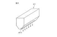
図4は、対向部材の他の例としてのガスノズルの構成を図解的に示す斜視図である。
ガスノズル41は、対向板13に代えて、アーム14の先端部に取り付けられる。ガスノズル41は、略直方体形状をなし、その下端面にスリット状の吐出口411を有している。吐出口411は、たとえば、0.2mm×60mmの寸法で形成されている。ガスノズル41の内部には、吐出口411と連通するガス流路(図示せず)が形成されている。このガス流路には、図示しないガス供給管を通してガスが供給される。ガス流路に供給されるガスは、吐出口411から下方に向けて吐出される。ガスとしては、たとえば、窒素ガスなどの不活性ガスが採用される。Therefore, the processing liquid can be evenly distributed over the entire surface of the wafer W without increasing the flow rate of the supplied processing liquid and the rotation speed of the wafer W.
FIG. 4 is a perspective view schematically showing a configuration of a gas nozzle as another example of the facing member.
The
ガスノズル41は、対向部材移動機構15(図1参照)により、回転中のウエハWの上面に形成されている液膜(ウエハWの中央部)と対向する位置に移動される。この移動が完了した状態で、吐出口411の長手方向がウエハWの回転半径方向に沿っている。その後、吐出口411からガスが吐出される。すると、その吐出口411から吐出されるガスにより、液膜の表層部分の一部が押し潰される。言い換えれば、液膜の表面の一部が吐出口411から吐出されるガスにより決壊される。そして、その状態で、対向部材移動機構15により、ガスノズル41がウエハWの周縁部と対向する位置に向けて水平移動される。ガスノズル41が移動されると、その決壊された部分から処理液がウエハWの周縁に向けて流れる。ウエハWが回転されているので、ガスノズル41がウエハWの中央部に対向する位置からウエハWの周縁部に対向する位置に向けて移動されると、液膜から流れ出る処理液が液膜の周囲に渦を描き、これにより液膜の径が増大していく。その結果、液膜を拡張させることができる。 The
よって、ガスノズル41が採用される構成によっても、対向板13が採用された構成と同様に、供給される処理液の流量およびウエハWの回転速度を増大させることなく、ウエハWの表面の全域に処理液をむらなく行き渡らせることができる。
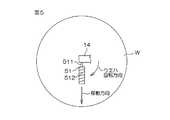
図5は、対向部材の他の例としてのツイスト部材が採用された構成を図解的に示す平面図である。Therefore, even in the configuration in which the
FIG. 5 is a plan view schematically showing a configuration in which a twist member as another example of the opposing member is employed.
ツイスト部材51は、略円柱状をなしている。アーム14の先端部には、水平方向に延びる軸511が保持されており、ツイスト部材51は、その軸511に回転自在に支持されている。ツイスト部材51の周面には、螺旋状の溝512が形成されている。また、ツイスト部材51は、塩ビまたはPTFE(Polytetrafluoroethylene)からなり、その周面には、親水化処理が施されている。 The
ツイスト部材51は、対向部材移動機構15(図1参照)により、回転中のウエハWの上面に形成されている液膜(ウエハWの中央部)と対向する位置に移動される。この移動が完了した状態で、ツイスト部材51の長手方向(回転軸線方向)がウエハWの回転半径方向に沿っている。その後、対向部材移動機構15により、ツイスト部材51がウエハWの上面に近づけられ(下降され)、ツイスト部材51の周面がウエハWの上面の中央部に形成されている液膜に接触(接液)される。このとき、ウエハWが回転しているので、液膜を形成している処理液は、ツイスト部材51の溝512に入り込む。そして、溝512に処理液が入り込むことにより、ツイスト部材51が軸511を中心に回転し、このツイスト部材51の回転により、ツイスト部材51とウエハWの上面との間に処理液が引き込まれる。 The
その後、ウエハWの上面への処理液の供給が継続されたまま、対向部材移動機構15により、ツイスト部材51が、その回転軸線方向に沿って、ウエハWの周縁部と対向する位置に向けて水平移動される。ツイスト部材51が移動されると、液膜の表面張力により、液膜を形成している処理液がツイスト部材51につられて移動する。ウエハWが回転されているので、ツイスト部材51がウエハWの中央部に対向する位置からウエハWの周縁部に対向する位置に向けて移動されると、ツイスト部材51と接触している処理液が液膜の周囲に渦を描き、これにより液膜の径が増大していく。その結果、液膜を拡張させることができる。なお、ツイスト部材51が回転し、また、ツイスト部材51の周面に親水化処理が施されているので、ツイスト部材51の移動時においても、ツイスト部材51の周面と処理液との接触状態が良好に維持される。 Thereafter, while the supply of the processing liquid to the upper surface of the wafer W is continued, the counter
よって、ツイスト部材51が採用される構成によっても、対向板13が採用された構成と同様に、供給される処理液の流量およびウエハWの回転速度を増大させることなく、ウエハWの表面の全域に処理液をむらなく行き渡らせることができる。
図6は、対向部材の他の例としてのディスク部材が採用された構成を図解的に示す平面図である。Therefore, even in the configuration in which the
FIG. 6 is a plan view schematically showing a configuration in which a disk member as another example of the opposing member is employed.
ディスク部材61は、PVA(polyvinyl alcohol)、PE(Polyethylene)、ウレタン、あるいはシリコン等の材質でできたスポンジなどの多孔質材料からなり、ディスク状(扁平な略円柱状)をなしている。アーム14の先端部には、鉛直方向に沿って垂下する軸611が回転自在に保持されており、ディスク部材61は、その軸611に取り付けられている。軸611には、図示しない回転駆動源からの回転駆動力が入力されるようになっている。 The
ディスク部材61は、対向部材移動機構15(図1参照)により、回転中のウエハWの上面に形成されている液膜(ウエハWの中央部)と対向する位置に移動される。その後、対向部材移動機構15により、ディスク部材61がウエハWの上面に近づけられ(下降され)、ディスク部材61の下面がウエハWの上面の中央部に形成されている液膜に接触(接液)される。また、軸611に入力される回転駆動力により、ディスク部材61は、ウエハWの回転方向と同方向に回転される。 The
その後、ウエハWの上面への処理液の供給が継続されたまま、対向部材移動機構15により、ディスク部材61が、その回転軸線方向に沿って、ウエハWの周縁部と対向する位置に向けて水平移動される。ディスク部材61が移動されると、多孔質材料の吸水性および液膜の表面張力により、液膜を形成している処理液がディスク部材61につられて移動する。ウエハWが回転されているので、ディスク部材61がウエハWの中央部に対向する位置からウエハWの周縁部に対向する位置に向けて移動されると、ディスク部材61と接触している処理液が液膜の周囲に渦を描き、これにより液膜の径が増大していく。その結果、液膜を拡張させることができる。なお、ディスク部材61の周面に親水化処理が施されているので、ディスク部材61の移動時においても、ディスク部材61の周面と処理液との接触状態が良好に維持される。 Thereafter, while the supply of the processing liquid to the upper surface of the wafer W is continued, the counter
よって、ディスク部材61が採用される構成によっても、対向板13が採用された構成と同様に、供給される処理液の流量およびウエハWの回転速度を増大させることなく、ウエハWの表面の全域に処理液をむらなく行き渡らせることができる。
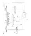
図7は、対向部材の他の例としての処理液ノズルが採用された基板処理装置の構成を図解的に示す断面図である。Therefore, even in the configuration in which the
FIG. 7 is a cross-sectional view schematically showing a configuration of a substrate processing apparatus in which a processing liquid nozzle as another example of the facing member is employed.
処理液ノズル71は、対向板13に代えて、アーム14の先端部に取り付けられる。処理液ノズル71には、ノズル8から吐出される処理液と同種の処理液が供給される供給管711が接続されている。供給管711には、制御部16により開閉が制御されるバルブ712が介装されている。
処理液ノズル71は、対向部材移動機構15により、回転中のウエハWの上面に形成されている液膜(ウエハWの中央部)と対向する位置に移動される。その後、バルブ712が開かれて、処理液ノズル71から処理液が吐出される。すると、その処理液ノズル71から吐出される処理液により、液膜の表層部分の一部が押し潰される。言い換えれば、液膜の表面の一部が吐出口411から吐出される処理液により決壊される。そして、その状態で、対向部材移動機構15により、処理液ノズル71がウエハWの周縁部と対向する位置に向けて水平移動される。処理液ノズル71が移動されると、その決壊された部分から処理液がウエハWの周縁に向けて流れる。ウエハWが回転されているので、処理液ノズル71がウエハWの中央部に対向する位置からウエハWの周縁部に対向する位置に向けて移動されると、液膜から流れ出る処理液が液膜の周囲に渦を描き、これにより液膜の径が増大していく。その結果、液膜を拡張させることができる。The
The processing
よって、処理液ノズル71が採用される構成によっても、対向板13が採用された構成と同様に、供給される処理液の流量およびウエハWの回転速度を増大させることなく、ウエハWの表面の全域に処理液をむらなく行き渡らせることができる。
以上、本発明のいくつかの実施形態について説明したが、本発明は、さらに他の形態で実施することも可能である。Therefore, even in the configuration in which the
As mentioned above, although several embodiment of this invention was described, this invention can also be implemented with another form.
たとえば、本発明に係る基板処理装置は、基板の表面からシリコン酸化膜を除去する処理に限らず、処理液を用いる処理に広く使用することができる。ただし、本発明の効果は、基板の表面が疎水性を示す場合にとくに顕著に発揮される。表面が疎水性を示す基板に対する処理としては、シリコン酸化膜を除去する処理以外に、(酸化性処理液を用いずに)レジストを除去する処理を例示することができる。 For example, the substrate processing apparatus according to the present invention is not limited to the processing for removing the silicon oxide film from the surface of the substrate, but can be widely used for processing using a processing solution. However, the effect of the present invention is particularly prominent when the surface of the substrate exhibits hydrophobicity. Examples of the treatment for the substrate having a hydrophobic surface include a treatment for removing the resist (without using an oxidizing treatment solution) in addition to the treatment for removing the silicon oxide film.
その他、特許請求の範囲に記載された事項の範囲で種々の設計変更を施すことが可能である。 In addition, various design changes can be made within the scope of matters described in the claims.
1 基板処理装置
2 ウエハ回転機構
3 処理液供給機構
13 対向板
14 アーム
15 対向部材移動機構
16 制御部
41 ガスノズル
51 ツイスト部材
61 ディスク部材
71 処理液ノズル
132 下面
133 湾曲面
411 吐出口
W ウエハDESCRIPTION OF
Claims (12)
Translated fromJapanese前記基板回転手段により回転される基板の上面の中央部に処理液を供給する処理液供給手段と、
前記基板回転手段により回転される基板の上面に対向配置される対向部材と、
前記処理液供給手段による処理液の供給と並行して、前記対向部材を基板の中央部に対向する位置から周縁部に対向する位置へと移動させ、その移動によって、当該基板の中央部を覆っている処理液の液膜を基板の周縁に向けて拡張させる液膜拡張手段とを含み、
前記対向部材は、基板の上面と平行な下面を有する略長方形板状をなすと共に、その長手方向が基板の回転半径方向に沿う対向板であり、前記対向板は、その下面から基板の回転方向の上流側に向けて延設され、外側に凸湾曲する湾曲面を有しており、
前記液膜拡張手段は、前記対向板の前記下面が前記液膜に接触するように前記対向板を配置し、前記対向板と前記液膜との接触状態を維持しつつ、前記対向板を基板の周縁部に対向する位置に向けて前記長手方向に沿う方向に移動させる、基板処理装置。A substrate rotating means for holding the substrate in a horizontal position and rotating it around an axis passing through the center of the substrate;
A processing liquid supply means for supplying a processing liquid to the central portion of the upper surface of the substrate rotated by the substrate rotating means;
A facing member disposed to face the upper surface of the substrate rotated by the substrate rotating means;
In parallel with the supply of the processing liquid by the processing liquid supply means, the counter member is moved from a position facing the central part of the substrate to a position facing the peripheral part, and the movement covers the central part of the substrate. the operation being liquid filmviewing contains a liquid film expanding means for expanding toward the periphery of thesubstrate,
The counter member has a substantially rectangular plate shape having a lower surface parallel to the upper surface of the substrate, and the longitudinal direction of the counter member is along the rotational radius direction of the substrate. The counter plate rotates from the lower surface to the substrate in the rotation direction. And has a curved surface that is convexly curved outward,
The liquid film expanding means arranges the counter plate so that the lower surface of the counter plate is in contact with the liquid film, and maintains the contact state between the counter plate and the liquid film while the counter plate is a substrate. The substrate processing apparatuswhich moves to the direction along the said longitudinal direction toward the position which opposes the peripheral part .
前記対向部材は、前記ノズルから離れた位置に配置されている、請求項1〜3のいずれか一項に記載の基板処理装置。 The said opposing member is a substrate processing apparatus as described in any one of Claims 1-3 arrange | positioned in the position away from the said nozzle.
回転中の基板の上面の中央部に処理液を供給する処理液供給工程と、
前記処理液供給工程と並行して、対向部材を基板の上面に対向配置し、前記対向部材を基板の中央部に対向する位置から周縁部に対向する位置へと移動させ、その移動によって、当該基板の中央部を覆っている処理液の液膜を基板の周縁に向けて拡張させる液膜拡張工程とを含み、
前記対向部材は、基板の上面と平行な下面を有する略長方形板状をなすと共に、その長手方向が基板の回転半径方向に沿う対向板であり、前記対向板は、その下面から基板の回転方向の上流側に向けて延設され、外側に凸湾曲する湾曲面を有しており、
前記液膜拡張工程では、前記対向板の前記下面が前記液膜に接触するように前記対向板が配置され、前記対向板と前記液膜との接触状態が維持されつつ、前記対向板が基板の周縁部に対向する位置に向けて前記長手方向に沿う方向に移動される、基板処理方法。A substrate rotation process in which the substrate is rotated in a horizontal posture around an axis passing through the center of the substrate;
A processing liquid supply step for supplying a processing liquid to the central portion of the upper surface of the rotating substrate;
In parallel with the processing liquid supply step, the opposing member is disposed opposite to the upper surface of the substrate, and the opposing member is moved from a position facing the central portion of the substrate to a position facing the peripheral portion. the treatment liquid film that covers the central portion of the substrateviewed contains a liquid film expansion step to expand toward the periphery of thesubstrate,
The counter member has a substantially rectangular plate shape having a lower surface parallel to the upper surface of the substrate, and the longitudinal direction of the counter member is along the rotational radius direction of the substrate. The counter plate rotates from the lower surface to the substrate in the rotation direction. And has a curved surface that is convexly curved outward,
In the liquid film expansion step, the counter plate is disposed so that the lower surface of the counter plate is in contact with the liquid film, and the counter plate is a substrate while maintaining a contact state between the counter plate and the liquid film. A substrate processing methodin which the substrateis moved in a direction along the longitudinal direction toward a position facing the peripheral edge of the substrate.
前記対向部材は、前記ノズルから離れた位置に配置されている、請求項7〜9のいずれか一項に記載の基板処理方法。 The substrate processing method according to claim 7, wherein the facing member is disposed at a position away from the nozzle.
Priority Applications (3)
| Application Number | Priority Date | Filing Date | Title |
|---|---|---|---|
| JP2008221863AJP5270263B2 (en) | 2008-08-29 | 2008-08-29 | Substrate processing apparatus and substrate processing method |
| US12/508,091US20100051055A1 (en) | 2008-08-29 | 2009-07-23 | Substrate processing apparatus and substrate processing method |
| TW098126712ATWI395282B (en) | 2008-08-29 | 2009-08-10 | Substrate processing apparatus and substrate processing method |
Applications Claiming Priority (1)
| Application Number | Priority Date | Filing Date | Title |
|---|---|---|---|
| JP2008221863AJP5270263B2 (en) | 2008-08-29 | 2008-08-29 | Substrate processing apparatus and substrate processing method |
Publications (2)
| Publication Number | Publication Date |
|---|---|
| JP2010056420A JP2010056420A (en) | 2010-03-11 |
| JP5270263B2true JP5270263B2 (en) | 2013-08-21 |
Family
ID=41723522
Family Applications (1)
| Application Number | Title | Priority Date | Filing Date |
|---|---|---|---|
| JP2008221863AExpired - Fee RelatedJP5270263B2 (en) | 2008-08-29 | 2008-08-29 | Substrate processing apparatus and substrate processing method |
Country Status (3)
| Country | Link |
|---|---|
| US (1) | US20100051055A1 (en) |
| JP (1) | JP5270263B2 (en) |
| TW (1) | TWI395282B (en) |
Families Citing this family (5)
| Publication number | Priority date | Publication date | Assignee | Title |
|---|---|---|---|---|
| JP5795917B2 (en) | 2010-09-27 | 2015-10-14 | 株式会社Screenホールディングス | Substrate processing apparatus and substrate processing method |
| JP6223839B2 (en)* | 2013-03-15 | 2017-11-01 | 東京エレクトロン株式会社 | Substrate liquid processing method, substrate liquid processing apparatus, and storage medium |
| JP7088810B2 (en)* | 2018-11-07 | 2022-06-21 | 株式会社Screenホールディングス | Board processing method and board processing equipment |
| JP7197376B2 (en)* | 2019-01-17 | 2022-12-27 | 東京エレクトロン株式会社 | Substrate processing method and substrate processing apparatus |
| KR102731766B1 (en)* | 2019-07-23 | 2024-11-20 | 주식회사 원익아이피에스 | Producing method of support substrate for supproting flexible substrate |
Family Cites Families (13)
| Publication number | Priority date | Publication date | Assignee | Title |
|---|---|---|---|---|
| US5975098A (en)* | 1995-12-21 | 1999-11-02 | Dainippon Screen Mfg. Co., Ltd. | Apparatus for and method of cleaning substrate |
| JPH09275086A (en)* | 1996-04-02 | 1997-10-21 | F O I:Kk | Substrate cleaning device |
| US6602382B1 (en)* | 1999-10-26 | 2003-08-05 | Tokyo Electron Limited | Solution processing apparatus |
| JP2005021894A (en)* | 1999-10-27 | 2005-01-27 | Tokyo Electron Ltd | Liquid treatment apparatus |
| TWI236944B (en)* | 2001-12-17 | 2005-08-01 | Tokyo Electron Ltd | Film removal method and apparatus, and substrate processing system |
| JP4185710B2 (en)* | 2002-06-07 | 2008-11-26 | 東京エレクトロン株式会社 | Substrate processing apparatus and substrate processing method |
| US7387455B2 (en)* | 2002-06-07 | 2008-06-17 | Tokyo Electron Limited | Substrate processing device, substrate processing method, and developing device |
| JP4734063B2 (en)* | 2005-08-30 | 2011-07-27 | 東京エレクトロン株式会社 | Substrate cleaning apparatus and substrate cleaning method. |
| JP4472630B2 (en)* | 2005-12-28 | 2010-06-02 | 大日本スクリーン製造株式会社 | Substrate processing equipment |
| JP4889331B2 (en)* | 2006-03-22 | 2012-03-07 | 大日本スクリーン製造株式会社 | Substrate processing apparatus and substrate processing method |
| JP4641964B2 (en)* | 2006-03-30 | 2011-03-02 | 大日本スクリーン製造株式会社 | Substrate processing apparatus and substrate processing method |
| EP1879216B1 (en)* | 2006-06-16 | 2009-02-25 | Tokyo Electron Limited | Liquid processing apparatus and method |
| JP2008016660A (en)* | 2006-07-06 | 2008-01-24 | Dainippon Screen Mfg Co Ltd | Method for treating substrate and substrate treating apparatus |
- 2008
- 2008-08-29JPJP2008221863Apatent/JP5270263B2/ennot_activeExpired - Fee Related
- 2009
- 2009-07-23USUS12/508,091patent/US20100051055A1/ennot_activeAbandoned
- 2009-08-10TWTW098126712Apatent/TWI395282B/ennot_activeIP Right Cessation
Also Published As
| Publication number | Publication date |
|---|---|
| US20100051055A1 (en) | 2010-03-04 |
| TWI395282B (en) | 2013-05-01 |
| JP2010056420A (en) | 2010-03-11 |
| TW201013816A (en) | 2010-04-01 |
Similar Documents
| Publication | Publication Date | Title |
|---|---|---|
| JP5698487B2 (en) | Substrate processing apparatus and substrate processing method | |
| JP6080291B2 (en) | Substrate processing method and substrate processing apparatus | |
| JP4976949B2 (en) | Substrate processing equipment | |
| TWI626676B (en) | Substrate liquid processing method,substrate liquid processing device and storage medium | |
| JP4425913B2 (en) | Substrate cleaning method and computer-readable storage medium | |
| US9768042B2 (en) | Substrate processing method and substrate processing apparatus | |
| JP2008047629A (en) | Device and method for processing substrate | |
| KR20080028921A (en) | Liquid treatment device and liquid treatment method | |
| JP2004119717A (en) | Method and apparatus of processing substrate | |
| JP2012094836A (en) | Substrate processing apparatus and substrate processing method | |
| JP4607755B2 (en) | Substrate cleaning method, substrate cleaning apparatus, control program, and computer-readable storage medium | |
| JP5270263B2 (en) | Substrate processing apparatus and substrate processing method | |
| JP3704260B2 (en) | Substrate cleaning apparatus and substrate cleaning method | |
| JP7290695B2 (en) | Cleaning equipment for ultrasonic cleaning equipment and cleaning tools | |
| JP6143589B2 (en) | Substrate processing equipment | |
| JP4255459B2 (en) | Substrate cleaning apparatus and substrate cleaning method | |
| JP2008060299A (en) | Substrate treating device and method | |
| JP6782185B2 (en) | Substrate processing equipment and substrate processing method | |
| JP5323374B2 (en) | Developing apparatus and developing method | |
| JP4781253B2 (en) | Substrate processing apparatus and substrate processing method | |
| US11201067B2 (en) | Substrate treatment method and substrate treatment device | |
| JPH11330041A (en) | Device for processing substrate by etching liquid | |
| JP2008177584A (en) | Substrate processing method and substrate processing apparatus | |
| JP2009081370A (en) | Substrate cleaning method, and substrate cleaning device | |
| TWI559101B (en) | Developing apparatus and developing method |
Legal Events
| Date | Code | Title | Description |
|---|---|---|---|
| RD04 | Notification of resignation of power of attorney | Free format text:JAPANESE INTERMEDIATE CODE: A7424 Effective date:20100630 | |
| A621 | Written request for application examination | Free format text:JAPANESE INTERMEDIATE CODE: A621 Effective date:20110606 | |
| A977 | Report on retrieval | Free format text:JAPANESE INTERMEDIATE CODE: A971007 Effective date:20121001 | |
| A131 | Notification of reasons for refusal | Free format text:JAPANESE INTERMEDIATE CODE: A131 Effective date:20121101 | |
| A521 | Request for written amendment filed | Free format text:JAPANESE INTERMEDIATE CODE: A523 Effective date:20121218 | |
| TRDD | Decision of grant or rejection written | ||
| A01 | Written decision to grant a patent or to grant a registration (utility model) | Free format text:JAPANESE INTERMEDIATE CODE: A01 Effective date:20130418 | |
| A61 | First payment of annual fees (during grant procedure) | Free format text:JAPANESE INTERMEDIATE CODE: A61 Effective date:20130509 | |
| R150 | Certificate of patent or registration of utility model | Free format text:JAPANESE INTERMEDIATE CODE: R150 Ref document number:5270263 Country of ref document:JP Free format text:JAPANESE INTERMEDIATE CODE: R150 | |
| S533 | Written request for registration of change of name | Free format text:JAPANESE INTERMEDIATE CODE: R313533 | |
| R350 | Written notification of registration of transfer | Free format text:JAPANESE INTERMEDIATE CODE: R350 | |
| R250 | Receipt of annual fees | Free format text:JAPANESE INTERMEDIATE CODE: R250 | |
| R250 | Receipt of annual fees | Free format text:JAPANESE INTERMEDIATE CODE: R250 | |
| R250 | Receipt of annual fees | Free format text:JAPANESE INTERMEDIATE CODE: R250 | |
| R250 | Receipt of annual fees | Free format text:JAPANESE INTERMEDIATE CODE: R250 | |
| LAPS | Cancellation because of no payment of annual fees |