JP5269026B2 - Work machine ambient monitoring device - Google Patents
Work machine ambient monitoring deviceDownload PDFInfo
- Publication number
- JP5269026B2 JP5269026B2JP2010218156AJP2010218156AJP5269026B2JP 5269026 B2JP5269026 B2JP 5269026B2JP 2010218156 AJP2010218156 AJP 2010218156AJP 2010218156 AJP2010218156 AJP 2010218156AJP 5269026 B2JP5269026 B2JP 5269026B2
- Authority
- JP
- Japan
- Prior art keywords
- image
- camera
- monitor
- work machine
- displayed
- Prior art date
- Legal status (The legal status is an assumption and is not a legal conclusion. Google has not performed a legal analysis and makes no representation as to the accuracy of the status listed.)
- Expired - Fee Related
Links
Images


Classifications
- H—ELECTRICITY
- H04—ELECTRIC COMMUNICATION TECHNIQUE
- H04N—PICTORIAL COMMUNICATION, e.g. TELEVISION
- H04N7/00—Television systems
- H04N7/18—Closed-circuit television [CCTV] systems, i.e. systems in which the video signal is not broadcast
- B—PERFORMING OPERATIONS; TRANSPORTING
- B60—VEHICLES IN GENERAL
- B60R—VEHICLES, VEHICLE FITTINGS, OR VEHICLE PARTS, NOT OTHERWISE PROVIDED FOR
- B60R1/00—Optical viewing arrangements; Real-time viewing arrangements for drivers or passengers using optical image capturing systems, e.g. cameras or video systems specially adapted for use in or on vehicles
- E—FIXED CONSTRUCTIONS
- E02—HYDRAULIC ENGINEERING; FOUNDATIONS; SOIL SHIFTING
- E02F—DREDGING; SOIL-SHIFTING
- E02F9/00—Component parts of dredgers or soil-shifting machines, not restricted to one of the kinds covered by groups E02F3/00 - E02F7/00
- E02F9/24—Safety devices, e.g. for preventing overload
- E—FIXED CONSTRUCTIONS
- E02—HYDRAULIC ENGINEERING; FOUNDATIONS; SOIL SHIFTING
- E02F—DREDGING; SOIL-SHIFTING
- E02F9/00—Component parts of dredgers or soil-shifting machines, not restricted to one of the kinds covered by groups E02F3/00 - E02F7/00
- E02F9/26—Indicating devices
- E—FIXED CONSTRUCTIONS
- E02—HYDRAULIC ENGINEERING; FOUNDATIONS; SOIL SHIFTING
- E02F—DREDGING; SOIL-SHIFTING
- E02F9/00—Component parts of dredgers or soil-shifting machines, not restricted to one of the kinds covered by groups E02F3/00 - E02F7/00
- E02F9/26—Indicating devices
- E02F9/261—Surveying the work-site to be treated
- H—ELECTRICITY
- H04—ELECTRIC COMMUNICATION TECHNIQUE
- H04N—PICTORIAL COMMUNICATION, e.g. TELEVISION
- H04N7/00—Television systems
- H04N7/18—Closed-circuit television [CCTV] systems, i.e. systems in which the video signal is not broadcast
- H04N7/181—Closed-circuit television [CCTV] systems, i.e. systems in which the video signal is not broadcast for receiving images from a plurality of remote sources
Landscapes
- Engineering & Computer Science (AREA)
- Multimedia (AREA)
- Signal Processing (AREA)
- Mining & Mineral Resources (AREA)
- Civil Engineering (AREA)
- General Engineering & Computer Science (AREA)
- Structural Engineering (AREA)
- Mechanical Engineering (AREA)
- Component Parts Of Construction Machinery (AREA)
- Closed-Circuit Television Systems (AREA)
Description
Translated fromJapanese本発明は、油圧ショベル等からなる作業機械において、機械による作業の安全確保等のために設けられる作業機械の周囲監視装置に関するものである。 The present invention relates to a work machine surrounding monitoring device provided for ensuring the safety of work by a machine in a work machine such as a hydraulic excavator.
作業機械の一例として、例えば油圧ショベルは、自走式の作業機械であって、クローラ式またはホイール式の走行手段を備えた下部走行体を有するもので、この下部走行体には旋回装置を介して上部旋回体が設置されている。上部旋回体には土砂の掘削等の作業を行う作業手段が設けられている。作業手段は、上部旋回体に俯仰動作可能に連結したブームと、このブームの先端に上下方向に回動可能に連結したアームとを備え、土砂の掘削等の作業を行うバケットはフロントアタッチメントとして、アームの先端にリンク機構を介して連結されており、これらにより多関節作業機構を構成している。 As an example of a working machine, for example, a hydraulic excavator is a self-propelled working machine having a lower traveling body provided with a crawler type or wheel type traveling means, and this lower traveling body is provided with a turning device. The upper revolving structure is installed. The upper turning body is provided with working means for performing work such as excavation of earth and sand. The working means includes a boom that is connected to the upper swing body so as to be able to move up and down, and an arm that is connected to the tip of the boom so as to be able to rotate in the vertical direction. It is connected to the tip of the arm via a link mechanism, thereby constituting an articulated working mechanism.
油圧ショベル等の自走式作業機械において、作業の安全を確保し、また作業機械の操作性の向上を図るために、上部旋回体の周囲を監視する周囲監視装置を設けたものは、従来から知られている。この周囲監視装置は、上部旋回体にカメラを装着すると共に、運転室において、オペレータが着座する運転席の前方位置にモニタを設置することにより構成され、カメラで撮影した画像は動画状態の映像としてモニタに表示される。 In a self-propelled work machine such as a hydraulic excavator, in order to ensure work safety and to improve the operability of the work machine, there has been conventionally provided a surrounding monitoring device for monitoring the periphery of the upper swing body. Are known. This perimeter monitoring device is configured by mounting a camera on the upper swing body and installing a monitor in the operator's cab in front of the driver's seat where the operator is seated. Displayed on the monitor.
ところで、カメラは上部旋回体に固定的に保持されており、その視野範囲は限られている。作業対象となる前方位置の視野が必要なのは当然のことながら、走行の安全性の確保等のためには、上部旋回体の後方及び左右の両側方における視野も必要である、作業機械の周囲において、できるだけ広い範囲の視野を得るために、上部旋回体には複数のカメラを装着する構成としたものが従来から用いられている。これによって、上部旋回体のほぼ全周にわたって死角をなくすことができ、もって作業の安全確保及び作業機械の操作性の向上が図られる。 By the way, the camera is fixedly held by the upper swing body, and its visual field range is limited. Needless to say, it is necessary to have a field of view at the front position that is the work target, but it is also necessary to have a field of view at the rear of the upper revolving structure and on both the left and right sides in order to ensure driving safety. In order to obtain a field of view as wide as possible, a structure in which a plurality of cameras are mounted on the upper swing body has been conventionally used. As a result, the blind spot can be eliminated over almost the entire circumference of the upper swing body, thereby ensuring work safety and improving the operability of the work machine.
複数のカメラで取得した作業機械の周囲の画像、つまりカメラ画像は、通常、モニタに一括表示されるのではなく、いずれか必要なカメラ画像が選択的に表示される。このモニタへの表示の選択はオペレータの操作によることになる。各カメラからの画像のうち、所望とするものを表示させるために、切換スイッチをモニタに付設するか、リモートコントロール装置等に設けて、その切換スイッチをオペレータが手動で操作して目的とする画像を表示する構成とするのが一般的である。 Images of the surroundings of the work machine acquired by a plurality of cameras, that is, camera images are usually not displayed on the monitor at once, but any necessary camera images are selectively displayed. The selection of the display on the monitor depends on the operator's operation. In order to display desired images among the images from each camera, a changeover switch is attached to the monitor or provided on a remote control device or the like, and the changeover switch is manually operated by an operator to obtain a desired image. Is generally configured to display.
ただし、複数のカメラが設置されていることから、目的とする画像が表示されるまでに、切換スイッチを複数回切り換えなければならないこともあり、オペレータは画像切換操作に手間取ることがある。しかも、作業機械を操作している間にもモニタを切り換える必要があり、この画像切換操作の操作性に難点がある。 However, since a plurality of cameras are installed, it may be necessary to switch the changeover switch a plurality of times before the target image is displayed, and the operator may be troublesome in the image changeover operation. In addition, it is necessary to switch the monitor while operating the work machine, and there is a difficulty in the operability of this image switching operation.
以上の点を考慮して、カメラ画像が順次切り換わるように設定することにより、画像毎の切換操作の必要性をなくしたものが特許文献1に開示されている。この特許文献1では、全てのカメラ画像を順次表示させるだけでなく、切り換わり手順の変更や一部のカメラ画像を表示しないようにするスキップ設定をも可能にしている。 In consideration of the above points, Patent Document 1 discloses a configuration in which the camera image is set so as to be switched sequentially, thereby eliminating the need for a switching operation for each image. In this patent document 1, not only all the camera images are displayed sequentially, but also the switching procedure can be changed and a skip setting for not displaying some of the camera images is also possible.
ところで、カメラ画像では距離感を正確に把握するのが困難な場合がある。例えば、上部旋回体を旋回させる操作時に、周囲の安全を確認するが、作業機械の近傍に作業者等が立ち入っていたり、構築物等の障害物が作業機械の近傍に存在していたりしている状態で、上部旋回体の旋回させたときにそれらと接触するか否かをカメラ画像だけからでは正確に判断できないことがある。また、下部走行体を後進させる際にも、作業機械が作業者や障害物等にどの程度まで接近しているかについて、さらには溝等の凹所の存在や位置を正確に把握できないこともある。作業機械の旋回時や後進時には、周囲に衝突を回避し、また進入停止を行うべき要回避対象となるものがあっても、カメラ画像を周囲の監視のための唯一の手掛かりとしたのでは、この種の要回避対象の存在の有無及び形状や大きさは確認できるものの、作業機械から要回避対象までの正確な距離を認識することはできないことがある。 By the way, it may be difficult to accurately grasp the sense of distance in the camera image. For example, when turning the upper swing body, the surrounding safety is confirmed, but an operator or the like enters the vicinity of the work machine, or an obstacle such as a structure exists near the work machine. In this state, it may not be possible to accurately determine whether or not the upper revolving unit contacts with the upper revolving unit only from the camera image. Also, when the lower traveling body is moved backward, it may not be possible to accurately grasp the extent to which the work machine is approaching an operator or an obstacle, and further the presence or position of a recess such as a groove. . When the work machine is turning or reversing, even if there are things that should be avoided and should be stopped, the camera image is the only clue for monitoring the surroundings. Although the existence, shape, and size of this kind of avoidance target can be confirmed, it may not be possible to recognize the exact distance from the work machine to the avoidance target.
ところで、カメラをある高さから斜め下方向に視野を向けて撮影し、このカメラ画像を画像変換処理すると、仮想視点からの画像に変換することができる。仮想視点画像として、視点を上方位置とした上方視点画像は俯瞰状態の画像となり、この俯瞰画像をモニタに表示すると、要回避対象までの距離を正確に把握することができる。作業機械において、俯瞰画像を表示することにより周囲の監視を行う装置が、例えば特許文献2に開示されている。この特許文献2では、作業機械としての油圧ショベルの後方と、左側方との所定の位置にカメラを装着して、これらのカメラの光軸を斜め下方に向け、後方及び側方に広い視野を持った画像を取得して上方視点となるように視点変換した俯瞰画像をモニタに表示することによって、周辺監視画面を取得するようにしている。 By the way, if a camera is photographed with a visual field directed downward from a certain height and this camera image is subjected to image conversion processing, it can be converted into an image from a virtual viewpoint. As the virtual viewpoint image, the upper viewpoint image with the viewpoint as the upper position is an image in a bird's-eye view. When this bird's-eye view image is displayed on the monitor, the distance to the avoidance target can be accurately grasped. For example,
このように俯瞰画像をモニタに表示すると、上部旋回体から要回避対象までの距離を正確に把握できることになる。従って、作業機械を後進させたり、旋回させたりする際に、このモニタの映像によって周囲の安全を確認することができる。また、作業機械としての油圧ショベルには、上部旋回体における運転室の右側に土砂の掘削等を行う作業手段が設置されている。従って、運転室内でのオペレータの肉眼による視野は、この作業手段により妨げられるので、この方向にも視野が必要となる。特許文献2において、カメラを上部旋回体の後方の位置だけではなく、右方の側部にも設けているのはこのためである。 When the bird's-eye view image is displayed on the monitor in this way, the distance from the upper swing body to the avoidance target can be accurately grasped. Therefore, when the work machine is moved backward or turned, the surrounding safety can be confirmed by the image of the monitor. In addition, working means for excavating soil and the like are installed on the right side of the cab of the upper swing body in the hydraulic excavator as a work machine. Therefore, the visual field of the operator's naked eye in the cab is obstructed by this working means, and thus a visual field is also required in this direction. For this reason, in
上方視点による俯瞰画像は画像処理して生成した画像であり、実体像ではない。従って、俯瞰画像は距離測定のためには有益な情報ではあるものの、この俯瞰画像に表示されている像の実際の形や大きさ等を正確に把握するのは必ずしも容易ではない。例えば、要回避対象が可動なものであるか、固定的なものであるかによっては、対処の仕方が変わってくる。要回避対象が可動な場合には、警報を発したり、所定時間だけ作業機械を待機させたりすることによって、相手側を危険な領域から退避させることができる。一方、要回避対象が固定的なものであれば、作業機械を迂回させるように走行させる必要がある。また、障害物であったとしても、その高さ等の関係から乗り越えることができるものもあれば、迂回しなければ通過できないこともある。俯瞰画像からこの種の判定を行うのは適切ではない。さらに、地面に凹凸があったり、傾斜していたりする場合には、それが俯瞰画像に反映されないこともある。Overhead by upper viewpoint image is an image generated by physical imageZosho, not the entity image. Therefore, although the overhead image is useful information for distance measurement, it is not always easy to accurately grasp the actual shape and size of the image displayed on the overhead image. For example, the way to deal with changes depending on whether the avoidance target is movable or fixed. When the avoidance target is movable, it is possible to evacuate the other party from the dangerous area by issuing an alarm or waiting the work machine for a predetermined time. On the other hand, if the object to be avoided is fixed, it is necessary to run the work machine so as to detour. Moreover, even if it is an obstacle, there are things that can be overcome due to its height, etc., and there are cases where it cannot pass unless it is detoured. It is not appropriate to make this type of determination from an overhead image. Furthermore, when the ground surface is uneven or inclined, it may not be reflected in the overhead view image.
カメラにより撮影して、このカメラ画像から俯瞰画像を生成している。このカメラ画像からは、被写体の形や大きさ、高さ等、様々な情報を取得できる。従って、このカメラ画像としてモニタに表示すれば、要回避対象の実体像を認識でき、周囲監視という目的の観点から望ましいものとなる。ただし、モニタは作業機械の運転室という限られた空間に設置されるものであり、しかもオペレータは前窓から肉眼による前方を視認する際に、前方にモニタが存在し、このモニタのサイズがあまり大きくなっていると、前方視野が制限されてしまう。従って、俯瞰画像とカメラ画像とを同時に並列的に表示することは望ましくはない。 An image is taken by a camera, and an overhead image is generated from the camera image. Various information such as the shape, size, and height of the subject can be acquired from the camera image. Therefore, if this camera image is displayed on the monitor, the entity image to be avoided can be recognized, which is desirable from the viewpoint of surrounding monitoring. However, the monitor is installed in a limited space called the operator's cab of the work machine. Moreover, when the operator visually recognizes the front with the naked eye from the front window, there is a monitor in front, and the size of the monitor is not so large. If it is larger, the front field of view is limited. Therefore, it is not desirable to display the overhead image and the camera image in parallel at the same time.
本発明は以上の点に鑑みてなされたものであって、その目的とするところは、作業機械の周囲を監視するに当って、周囲監視装置を操作する者の簡単な操作により監視に必要な情報を的確に取得できるようにすることにある。 The present invention has been made in view of the above points. The object of the present invention is to monitor the surroundings of a work machine by a simple operation of a person who operates the surroundings monitoring device. It is to be able to acquire information accurately.
前述した目的を達成するために、本発明は、作業機械に複数のカメラを設置して、これら各カメラで取得したカメラ画像に基づく信号処理を行って、上方視点となるように視点変換し、俯瞰画像としてモニタに表示する作業機械の周囲監視装置であって、前記複数のカメラは、前記作業機械の後方視野を撮影する後方カメラと、左右両側の側方視野を撮影する2個の側方カメラとからなり、前記各カメラにより撮影した各個別俯瞰画像を合成した合成俯瞰画像を前記モニタに表示する画像合成手段が設けられ、前記モニタには、作業機械の平面図をグラフィック化した表示キャラクタとして表示し、前記画像合成手段により合成された合成俯瞰画像は、前記表示キャラクタの後方位置に前記後方カメラからのカメラ画像に基づく後方俯瞰画像と、左右の両側位置にそれぞれ左右の側方カメラからのカメラ画像に基づく左右の側方俯瞰画像とした監視用パノラマ画像となし、さらに、前記作業機械の前方を視野範囲とする前方カメラを備え、この前方カメラは前記画像合成手段により合成されず、カメラ画像として前記モニタに表示するようになし、前記モニタに表示されている前記合成俯瞰画像に重畳させて、この合成俯瞰画像を構成する前記各個別俯瞰画像の少なくとも1つの画像を視点変換する前のカメラ画像を拡大して表示するための切換手段を有する構成としたことをその特徴とするものである。
In order to achieve the above-described object, the present invention installs a plurality of cameras on a work machine, performs signal processing based on the camera images acquired by each of these cameras, converts the viewpoint to become an upper viewpoint, An apparatus for monitoring the surroundings of a work machine that displays a bird's-eye view image on a monitor,wherein the plurality of cameras include a rear camera that captures a rear field of view of the work machine and two lateral sides that capture a lateral field of view on both the left and right sides. consists of a camera, the synthesized composite overhead image the individual bird's-eye view image taken by eachcamera image synthesis means for displaying on said monitoris provided, on the monitor, the display character that graphic the plan view of a work machine The synthesized overhead image displayed by the image synthesizing means is a rear overhead image based on the camera image from the rear camera at the rear position of the display character. A panoramic image for monitoring as left and right side overhead images based on the camera images from the left and right side cameras respectively on the left and right side positions, and further comprising a front camera having a field of view in front of the work machine, The front camera is not synthesized by the image synthesizing means, and is displayed on the monitor as a camera image, and is superimposed on the synthesized overhead image displayed on the monitor to constitute each synthesized overhead image. It is characterizedby having a switching means for enlarging and displaying a camera image before the viewpoint conversion of at least one image of the individual overhead image.
作業機械の周囲監視のためには、少なくとも後方の視野が必要であり、また作業機械が油圧ショベルや油圧クレーン等である場合には、作業手段は運転室の右側に配置されるのが一般的であるから、右側方向の視野についても、周囲監視の対象とする。さらに運転室の左側も、少なくとも斜め後方はオペレータの肉眼による視野が得にくいものである。従って、例えば、作業機械の後方視野を撮影する後方カメラと、左右両側の側方視野を撮影する2個の側方カメラとから構成することができる。そして、これら後方カメラ及び側方カメラによりそれぞれの箇所で取得したカメラ画像を各領域の俯瞰画像に変換する。なお、運転室と作業手段との位置関係等によっては、運転室内で着座しているオペレータにとってさらに別の死角となる部位が異なる場合もある。従って、設置されるカメラの数及びそれらの設置位置については、前述以外にも設けることができ、その配置はオペレータにとって死角となる部位であって、安全確保のために、視野が必要となる部位を基準として適宜設定される。 In order to monitor the surroundings of the work machine, at least a rear view is required. When the work machine is a hydraulic excavator, a hydraulic crane, or the like, the work means is generally arranged on the right side of the cab. Therefore, the visual field in the right direction is also subject to ambient monitoring. Further, the left side of the operator's cab is difficult to obtain the visual field of the operator's naked eye at least diagonally backward. Therefore, for example, it can be comprised from the rear camera which image | photographs the back visual field of a working machine, and the two side cameras which image | photograph the lateral visual field of both right and left sides. And the camera image acquired in each location with these back cameras and a side camera is converted into the bird's-eye view image of each area. Depending on the positional relationship between the driver's cab and the working means, there may be a case where a part that becomes another blind spot for the operator seated in the driver's cab is different. Therefore, the number of cameras to be installed and their installation positions can be provided in addition to those described above, and the arrangement is a part that is a blind spot for the operator and a part that requires a field of view to ensure safety. Is set as appropriate based on the above.
運転室の前方はオペレータの肉眼による視野が得られるので、必ずしも前方の俯瞰画像を取得することは必要ではないが、前方側にも俯瞰画像を取得することも可能である。また、オペレータは前方視野は直接取得できるといっても、死角となる方向がない訳ではない。例えば、前方が窪んでいる場合には、その窪みの底部はオペレータの肉眼による確認が困難なことがある。また、作業機械の上方の状況を確認するのが困難な場合もある。そこで、運転室の前方にもカメラを設けて、このカメラで補助的な視野を確保することができる。なお、この場合には、前方カメラの画像は視点変換することなく、カメラ画像をそのまま表示することになる。 Since the operator's naked eye can be obtained in front of the operator's cab, it is not always necessary to acquire a front bird's-eye view image, but it is also possible to acquire a bird's-eye view image on the front side. Further, even though the operator can directly acquire the front view, it does not mean that there is no direction that becomes a blind spot. For example, when the front is depressed, it is sometimes difficult to confirm the bottom of the depression with the naked eye of the operator. In addition, it may be difficult to confirm the situation above the work machine. Therefore, a camera can be provided in front of the cab, and an auxiliary visual field can be secured with this camera. In this case, the camera image is displayed as it is without converting the viewpoint of the image of the front camera.
各カメラで取得したカメラ画像を個別俯瞰画像として、これら個別俯瞰画像を合成して合成俯瞰画像を生成することから、全てのカメラの高さ位置及び光軸の水平面に対する角度を一致させるようにする。また、左右の両側の側方の個別俯瞰画像と、後方の個別俯瞰画像との間の移行部には多少の欠落箇所があっても、その欠落箇所が僅かなものであれば差し支えないが、端部を合わせて連続的な画像とするのが望ましい。このためには、例えば後方俯瞰像の両端を各側方俯瞰画像の端部を部分的に重ね合わせて、画像のブレンディング結合処理を行うようにすれば良い。 The camera images acquired by each camera are used as individual overhead images, and these individual overhead images are combined to generate a combined overhead image. Therefore, the height positions of all cameras and the angles of the optical axes with respect to the horizontal plane are matched. . In addition, even if there are some missing parts in the transition part between the individual overhead view images on the left and right sides and the individual overhead view on the back, there is no problem if the missing parts are slight, It is desirable to combine the edges into a continuous image. For this purpose, for example, the both ends of the rear bird's-eye view image may be partially overlapped with the ends of the side bird's-eye view images to perform blending processing of the images.
モニタには、合成俯瞰画像が表示されるが、モニタの中央前方の部位に余白領域ができることになる。そこで、作業機械の前方にもカメラを設置して、このカメラからの画像をこの余白部分に表示することもできる。このように構成すると、建設機械の後方乃至側方に対する作業を行うために、モニタを視認したときに、前方の視野を含む作業機械の全周の安全確認を行うことができる。 A composite bird's-eye view image is displayed on the monitor, but a blank area is formed at a position in front of the center of the monitor. Therefore, a camera can be installed in front of the work machine, and an image from the camera can be displayed in the margin. If comprised in this way, in order to perform the operation | work with respect to the back thru | or the side of a construction machine, when a monitor is visually recognized, the safety check of the perimeter of the working machine including a front visual field can be performed.
作業機械の平面図をキャラクタ化し、これを表示キャラクタとしてモニタに表示し、また画像合成手段により合成される合成俯瞰画像としては、表示キャラクタを中心とし、後方位置に後方カメラからのカメラ画像に基づく後方俯瞰画像と、左右の両側位置にそれぞれ左右の側方カメラからのカメラ画像に基づく左右の側方俯瞰画像とを合成して表示することによって、作業機械を中心とした監視用パノラマ画像をモニタに表示することができる。また、このパノラマ画像に危険ゾーン、注意ゾーン等、適宜のゾーンを設定することもできる。 The plan view of the work machine is converted into a character and displayed on the monitor as a display character. The synthesized overhead image synthesized by the image synthesis means is based on the camera image from the rear camera at the rear position with the display character as the center. Monitor the panoramic image for monitoring centering on the work machine by combining and displaying the rear bird's-eye view image and the left and right side bird's-eye view images based on the camera images from the left and right side cameras. Can be displayed. Also, appropriate zones such as a danger zone and a caution zone can be set for this panoramic image.
切換手段によって、一部の俯瞰画像がカメラ画像に変換されるが、どの領域のカメラ画像が表示されているかを認識させるために、カメラ画像と、それを視点変換させた俯瞰画像との大半の部位が重畳するように表示すると、オペレータにとって混乱するのを防止できる。この場合、俯瞰画像がカメラ画像に切り換わるようにして表示することになるが、例えばカメラ画像を透視して、俯瞰画像が視認できるように表示することもできる。 A part of the overhead image is converted into a camera image by the switching means. In order to recognize which area of the camera image is displayed, most of the camera image and the overhead image obtained by converting the viewpoint image are displayed. Displaying the parts so as to overlap each other can prevent the operator from being confused. In this case, the overhead image is displayed so as to be switched to the camera image. However, for example, the camera image can be seen through so that the overhead image can be viewed.
個別俯瞰画像をカメラ画像に変換して表示させるための切換手段としては、通常はオペレータの手動による切換手段によることになるが、自動切換手段も可能であり、またこれらを併用するようにしても良い。手動による切換手段としては、主に切換用のスイッチとなるが、モニタには画像表示部と操作パネル部とから構成し、スイッチは操作パネル部に設けることができる。また、操作パネル部を独立のリモートコントロール装置として構成することができる。さらに、モニタをタッチパネル式のものとすることも可能である。そして、俯瞰画像からカメラ画像への切り換え、及びカメラ画像から俯瞰画像への切り換えは共に手動で切り換わるようにすることもでき、また俯瞰画像からカメラ画像への切り換えはスイッチ操作で行われ、所定の時間が経過すると、カメラ画像から俯瞰画像に復帰するように構成しても良い。 The switching means for converting an individual overhead image into a camera image and displaying it is usually a manual switching means by an operator, but an automatic switching means is also possible, and these may be used together. good. The manual switching means is mainly a switching switch. The monitor is composed of an image display unit and an operation panel unit, and the switch can be provided in the operation panel unit. Further, the operation panel unit can be configured as an independent remote control device. Furthermore, the monitor can be of a touch panel type. The switching from the overhead image to the camera image and the switching from the camera image to the overhead image can both be performed manually, and the switching from the overhead image to the camera image is performed by a switch operation. When the time elapses, the camera image may be restored to the overhead image.
画像の切り換えは操作レバー等の操作手段に連動させることもできる。例えば、上部旋回体が左右のいずれかの方向に旋回する際には、旋回時の前方側に位置する側方カメラからの画像を切り換え、作業機械が後進する際には、後方カメラからの画像を切り換えるようにすることもできる。そして、操作が終了した後、所定の時間が経過すると、元の不満画像に戻るように設定することができる。なお、このように操作レバー等と連動して自動的に切り換わる構成とした場合、より好ましくは手動による切り換えも可能な構成とするのが望ましい。 The image switching can be linked to an operation means such as an operation lever. For example, when the upper swing body turns in either the left or right direction, the image from the side camera located on the front side during the turn is switched, and when the work machine moves backward, the image from the rear camera Can also be switched. Then, after the operation is completed, when a predetermined time elapses, it can be set to return to the original dissatisfied image. In addition, when it is set as the structure which switches automatically in response to an operation lever etc. in this way, it is desirable to set it as the structure which can be switched manually.
作業機械の周囲を監視するに当って、カメラ画像と、このカメラ画像から視点変換を行った俯瞰画像とを切り換え表示可能にすることによって、作業機械を操作する操作者は、簡単な操作により周囲監視に必要な情報を的確に取得できる等の効果を奏する。 When monitoring the surroundings of the work machine, the operator who operates the work machine can perform the surroundings by a simple operation by making it possible to switch between the camera image and the bird's-eye view image converted from the camera image. There is an effect that information necessary for monitoring can be accurately acquired.
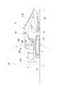
以下、図面に基づいて本発明の実施の形態について説明する。まず、図1及び図2に作業機械の一例としての油圧ショベルの構成を示す。図中において、1はクローラ式走行体からなる下部走行体であって、下部走行体1には旋回装置2を介して上部旋回体3が設けられている。 Hereinafter, embodiments of the present invention will be described with reference to the drawings. First, FIG.1 and FIG.2 shows the structure of the hydraulic excavator as an example of a working machine. In the figure, reference numeral 1 denotes a lower traveling body made of a crawler traveling body, and an upper revolving
上部旋回体3には、オペレータが搭乗して機械を操作するための運転室4が設置されており、また土砂の掘削等の作業を行う作業手段5が設けられている。作業手段5は運転室4の右手において、ほぼ並ぶような位置に設けられている。さらに、上部旋回体3には、運転室4及び作業手段5の後方位置に建屋6等が設けられており、最後端部にはカウンタウエイト7が設置されている。 The
作業手段5は、ブーム10,アーム11及びフロントアタッチメントとしてのバケット12から構成される土砂の掘削作業手段である。ブーム10は、その基端部が上部旋回体3のフレーム3aに連結ピンにより軸支されて俯仰動作可能となっている。ブーム10の先端にはアーム11が上下方向に回動可能に連結されており、さらにアーム11の先端にはバケット12が回動可能に連結されている。ブーム10の俯仰動作はブームシリンダ10aを駆動することにより行われる。アーム11はアームシリンダ11aにより、さらにバケット12はバケットシリンダ12aにより駆動される。 The working means 5 is earth and sand excavation working means including a
前述した構成を有する油圧ショベルにおいて、この油圧ショベルの操作者であるオペレータは運転室4内で、前方を向いた状態で操作を行うものであって、上部旋回体3の前方には十分広い視野が確保されている。また、運転室4の左側における斜め前方の視野も確保されている。ただし、左側であっても、斜め後方については、オペレータは振り返るようにしなければ直接視認をすることができない。また、運転室4の右側においては、作業手段5が設置されており、視野のかなりの部分がブーム10により妨げられることになり、実質的に肉眼による確認を行うことができない。さらに、上部旋回体3の後方については、建屋6及びカウンタウエイト7が位置しており、オペレータは運転室4の内部で振り返るようにしなければ視野が得られず、しかも建屋6及びカウンタウエイト7の上面は高い位置となっており、従ってオペレータは運転室4内で振り返る姿勢を取ったとしても、視野が得られるのは遠い位置であり、上部旋回体3に近い位置を視認することはできない。 In the hydraulic excavator having the above-described configuration, an operator who is an operator of the hydraulic excavator operates in the
以上のことから、上部旋回体3の後方及び左右の側方の監視を可能にするために、カメラ13B,13R,13Lをそれぞれ設置して補助的に視野を確保するようにしている。即ち、カウンタウエイト7の上面において、その左右のほぼ中間位置に後方カメラ13Bが設置されている。また、建屋6の左方向の上面には左側カメラ13Lが、さらに上部旋回体3の右側の位置には、建屋6またはタンクの上面には右側カメラ13Rが設けられている。ここで、後方カメラ13Bは上部旋回体3の後方の広い範囲の画像を取得するようになっており、この後方カメラ13Bと、左右の両側カメラ13R,13Lとによって、上部旋回体3の運転室4内で、オペレータが無理のない姿勢で得られる前方視野を除くほぼ全周にわたって視野が得られるようにしている。 From the above, in order to enable monitoring of the rear and left and right sides of the
このために、前述した各カメラ13B,13R,13Lのレンズの視野角と、それらの配設位置とによって、少なくとも各レンズの水平視野角はその一部がオーバーラップするように設定する。これによって、上部旋回体3の周囲において、ブラインドとなる箇所がなくなるようにしている。上部旋回体3の前方については、オペレータの肉眼による視野が得られているが、図1に示したように、上部旋回体3のフレームには前方カメラ13Fが設けられており、この前方カメラ13Fによって、上部旋回体3の前方の視野が得られるようにもなっている。 For this purpose, at least the horizontal viewing angles of the respective lenses are set to overlap with each other according to the viewing angles of the lenses of the
運転室4内には、図3に示したように、モニタ20が設置されており、前述した各カメラ13R〜13Fから取得した画像がこのモニタ20に動画状態にして表示されるようになっている。ここで、前方カメラ13Fではカメラ画像をそのまま表示されるが、後方カメラ13Bと、左右の両側カメラ13R,13Lで取得したカメラ画像はそのまま表示されるのではなく、上方視点となるように視点変換される。 As shown in FIG. 3, a
即ち、図1に示したように、後方カメラ13Bは上部旋回体3の後方に対して角度θをもった斜め下方に対物レンズの光軸を向けている。このときに、油圧ショベルの下部走行体1の接地面をLとしたときに、この接地面Lに対して角度θを持ったカメラ画像から、同図に示したように、仮想視点VFから接地面Lに対して光軸が垂直になるように座標変換した画像を作成する。これによって、角度θをもった斜め上方からのカメラ画像を俯瞰画像に変換することができる。この俯瞰画像はモニタ20に表示可能となっている。また、左右の両側カメラ13R,13Lも後方カメラ13Bと同様、接地面Lに対する光軸の傾斜角は角度θとする。ただし、運転室4内のオペレータからは見にくい部位に対して補助的視野を取得するためのものであって、本実施の形態では、前方カメラ13Fの光軸は斜め上方に向けられている。 That is, as shown in FIG. 1, the
以上のことから、カメラ13B,13R,13Lは、周囲監視のための画像を取得するためのカメラであり、前方カメラ13Fは、機械を操作するオペレータにとって補助視野を取得するためのカメラである。そして、これらカメラ13B,13R,13Lからの画像を座標変換して得られる俯瞰画像からなる周囲監視用の画像と、補助視野として機能する前方カメラ13Fからのカメラ画像がモニタ20に表示される。 From the above, the
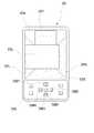
図3に示したモニタ20は、画像が表示される画像表示部20aと操作ボタン等を設けた操作パネル部20bとから構成されている。画像表示部20aには、その中央の位置に油圧ショベルの平面図がキャラクタ表示されており、この表示キャラクタ21の周囲にカメラ13B,13R,13Lで取得した画像からそれぞれ個別俯瞰画像として画像化の処理を行った後方俯瞰画像22Bと、左右の側方俯瞰画像22L,22Rとがそれぞれ対応する位置に表示されて、合成俯瞰画像となっている。これによって、表示キャラクタ21を中心としたパノラマ画像が表示されることになる。また、表示キャラクタ21の前方位置には、カメラ13Fで取得した前方視野の画像が表示されるようになっている。この前方画像は俯瞰画像化処理が行われていない前方カメラ画像22Fである。 The
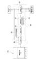
図4に画像処理装置30の回路構成を示す。図中において、カメラ13B,13R,13Lで撮影したカメラ画像、またカメラ13Fで撮影したカメラ画像は、画像補正部31に取り込まれる。この画像補正部31では、取り込まれたカメラ画像を、カメラ光学系パラメータ等に基づいて、収差補正や、コントラスト補正、色調補正等の画像補正を行うことによって、取得した画像の画質を向上させる。 FIG. 4 shows a circuit configuration of the
画像補正部31の出力側には、画像変換部32と、障害物検出部33とが並列に接続して設けられており、画像変換部32では、各々のカメラ画像から上方視点となるように視点変換がなされる。その結果、後方及び左右の側方における個別俯瞰画像22B,22L,22Rが生成される。そして、これらの個別俯瞰画像22B,22L,22Rはカメラ画像である前方カメラ画像22Fと共に画像合成部33によってモニタ20の画像表示部20aのそれぞれ所定の領域に貼り付けるように処置される。ここで、俯瞰画像22Bと左右の側方俯瞰画像22L,22Rとの境界部は部分的にオーバーラップさせるようにして画像が取得されるようになっている。そして、画像合成部34では、このオーバーラップした部位はブレンディング結合させることにより合成されて、合成俯瞰画像に変換される。これによって、合成俯瞰画像は、表示キャラクタ21を中心として周囲囲繞するように表示され、全体が切れ目のないパノラマ画像となる。 On the output side of the
前方カメラ画像22Fはカメラ画像がそのまま表示される。俯瞰画像22B,22L,22Rでは、信号処理され、実体像ではないために、画像に物体が表示されていることが認識可能できるが、変形した物体像となり、その実際の姿を正確に把握することができない場合がある。画像補正部31には、画像変換部32と並列に障害物検出部33が接続されている。そこで、画像補正部31から出力される各カメラ13B,13R,13Lからのカメラ画像に基づいて障害物(人,車両,構築物等)の有無を検出し、障害物が存在する場合には、この障害物が何であるか、その形状や大きさ等の情報を取得するようにしている。この処理を行うのが障害物検出部33である。 The
画像処理装置30の出力側には表示画像生成部35が設けられている。この表示画像生成部35にはキャラクタ発生部36が接続されており、このキャラクタ発生部36から表示キャラクタ21が出力される。この場合の表示キャラクタ21は作業機械としての油圧ショベルであり、平面図としてグラフィック化したものが表示される。また、画像合成部34で処理した合成俯瞰画像からなるパノラマ画像が表示キャラクタ21に合成される。ここで、表示キャラクタ21とパノラマ画像とは同一の縮尺寸法とする。一方、前方カメラ画像22Fは表示キャラクタ21の前方位置に表示されることになる。そして、この合成画像には、さらに障害物検出部33により検出された障害物の画像、つまり障害物画像Sが合成表示される。ここで、障害物画像Sは表示キャラクタ21と実質的に同じ縮尺寸法となし、またその位置は合成俯瞰画像から判定され、この判定位置に障害物画像Sが表示される。 A display
以上の画像データは画像処理装置30からモニタ20に伝送されて、このモニタ20を構成する画像表示部20aには、作業機械が稼働している場所において、この作業機械の周囲監視用のパノラマ画像として表示される。従って、モニタ20を目視すれば、周囲に要回避対象となる作業者が立ち入っている場合や、構築物等が存在している場合には、オペレータはその位置や大きさと共に的確に把握することができ、安全確保のために必要な操作を行うことができる。 The above image data is transmitted from the
作業機械は、その上部旋回体3は旋回中心を有し、この旋回中心を中心とした旋回半径を有するものであり、一般的には、360度にわたって旋回できるようになっている。そこで、モニタ20の画像表示部20aには、監視用パノラマ画像に合成して旋回半径を基準とした円を描くことにようになし、例えばその内部を上部旋回体3の旋回時において、衝突を回避すべき対象である要回避対象と接触するおそれのある領域を危険ゾーンZ1として設定し、また安全確保のために必要な範囲として、この円の外側に所定半径の円を描くようになし、これら2つの円の間の領域を注意ゾーンZ2として設定する。この注意ゾーンZ2の外側については、格別監視の必要がないものであり、モニタ20には注意ゾーンZ2までは完全に画像の範囲となるように、カメラ13R〜13Lのレンズの視野角及び光軸の接地面Lに対する傾斜角θが決定される。これに対して、オペレータの前方は肉眼で確認できるものであり、前方カメラ13Fは補助的な視野を確保するために設けられているために、他のカメラとは別個に視野を向けるようにする。本実施の形態では、前方カメラ13Fは、作業手段5を構成するバケット12が高所にあるときにも、このバケット12の状態を確認できるようにするために、斜め上方を視野とするように設定されている。 In the working machine, the
障害物画像Sが監視用パノラマ画像に合成されてモニタ20に表示されており、オペレータは運転室4内でモニタ20を注視することによって、この障害物画像Sが注意ゾーンZ2に入り込んでいるのを確認したときには、要回避対象に配慮した慎重な操作を行うことによって、安全で、しかも円滑な作業が可能となる。また、モニタ20上で障害物画像Sが危険ゾーンZ1の範囲内に位置していることが検出されると、作業機械の作動を停止させるなり、要回避対象が可動なものである場合には、警告を発してその位置から移動させたりする等の衝突回避に有効な対応策を取ることができる。 The obstacle image S is combined with the panoramic image for monitoring and displayed on the
作業機械の前方はオペレータの肉眼による視野が確保され、また側方から後方にかけての視野はモニタ20により得られるようになっており、しかもモニタ20から要回避対象との間の距離をほぼ正確に認識できるので、作業機械を稼働させている間であっても、オペレータが直接視認できない領域を含めて作業領域のほぼ全体を監視することができ、安全確認はもとより、作業手段5を作動させて土砂の掘削等の作業を行う際に、バケット12が届く範囲を認識するため等にも便利であり、作業手段5を用いた作業の作業性も向上する。 The visual field of the operator's naked eye is secured in front of the work machine, and the visual field from the side to the rear is obtained by the
ところで、前述した個別俯瞰画像22B,22L,22Rを合成した合成俯瞰画像からなる監視用パノラマ画像は、カメラ画像から座標変換して合成した画像であり、必ずしも正確に周囲の状況の実体を表しているものではない。モニタ20には障害物画像Sが表示されているものの、この障害物画像Sは物体像ではなく、信号処理を行って得た図形である。従って、要回避対象の実像を知ることは、オペレータにとって、安全確認上また作業の効率性等の点で有利である。 By the way, the monitoring panoramic image composed of the combined overhead images obtained by combining the individual
個別俯瞰画像22B,22L,22Rはカメラ13B,13R,13Lによるカメラ画像に基づいて生成されたものであり、カメラ画像により要回避対象の実体像が得られている。そこで、カメラ13B,13R,13Lのいずれかのカメラ画像をモニタ20に表示されている監視用パノラマ画像に重畳させて表示できるように構成している。 The individual
このために、モニタ20には、画像表示部20aの周囲、つまり額縁となる部位に操作パネル部20bが設けられている。この操作パネル部20bには、選択スイッチSW1〜SW5が設けられている。スイッチSW1は画像表示部20aにおける前方カメラ13Fからの前方カメラ画像22Fを拡大表示するためのものである。スイッチSW2は、図5に示したように、右側方俯瞰画像22Rが表示されている部位及びその近傍の部位に重畳させて右側カメラ13Lの右側カメラ画像23Rを拡大表示するためのものであり、スイッチSW3は、図6に示したように、後方俯瞰画像22Bが拡大表示されている部位及びその近傍の部位に重畳させて後方カメラ13Bの後方カメラ画像23Bを拡大表示するため、スイッチSW4は図7に示したように、左方俯瞰画像22Lが表示されている部位及びその近傍の位置に重畳させて左方カメラ13Rの左側カメラ画像23Lを表示するためのものである。さらに、スイッチSW1〜SW4の中央に位置するスイッチSW5はいずれかのカメラ画像表示態様から図3の監視用パノラマ画像が表示される状態に復帰させるための復帰スイッチである。 For this purpose, the
従って、例えば作業機械を後方に向けて走行するために、運転室4内に設けた走行レバー(図示せず)を操作するに当って、まず監視用パノラマ画像をモニタ20に表示させた状態で後方の安全確認を行う。後方に障害物画像Sが表示されている場合には、その回避措置を取ることになる。次いで、後方の状況、即ち平坦地であるか、地面に凹凸があるか、上り下りの坂道となっているか、左右に傾斜があるか等の確認をする必要があれば、モニタ20における操作パネル部20bのスイッチSW3を操作する。 Therefore, for example, when operating a travel lever (not shown) provided in the
これによって、図6に示したように、後方のカメラ画像が大きく表示されるので、オペレータは車両の後方における安全確認と状況把握とを行うことができる。そして、後方の状況確認を行った後には、スイッチSW5を操作することによって、元の監視用パノラマ画像がモニタ20における画像表示部20aに表示されることになる。また、作業機械の走行中に、作業者や他の車両等が進路を横切るようなことがあれば、オペレータはそれを認識して、走行を停止したり、警報を発生させたりすることにより対処できる。 As a result, as shown in FIG. 6, the rear camera image is displayed in a large size, so that the operator can confirm safety and grasp the situation behind the vehicle. Then, after confirming the rear situation, the original panoramic image for monitoring is displayed on the
ここで、前述した実施の形態では、画像の切り換えはスイッチ操作により行う構成としたが、モニタ20をタッチパネル式のものとすることができる。これによって、監視用パノラマ画像における表示キャラクタ21の周囲のいずれかに作業者がタッチすることによって、当該の部位のカメラ画像が表示されることになる。ここで、作業機械を操作するオペレータは、通常、手袋を着用しているので、モニタとしては、手袋を着用したままの手でも操作が可能なものを選択して用いる必要がある。 Here, in the above-described embodiment, the image is switched by a switch operation, but the
また、図8に示したように、モニタ120の画像表示部120aの周囲にほぼ均等な幅の額縁120bが形成されているものもある。この場合には、この額縁120bの各辺の中間位置にスイッチSW1〜SW4を配置することもできる。そして、いずれかのスイッチを操作することによりカメラ画像が表示される。スイッチを一度押動操作すると、各部位のカメラ画像が表示され、2度目に押動操作すると、元の監視用パノラマ画像が表示される状態に復元するように設定することもできる。なお、画像表示部120a内の表示については、図3に示したものと同じであるので、それと同一の符号を付して、その説明は省略する。 Further, as shown in FIG. 8, there is a case where a
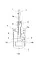
さらに、図9及び図10に示したように、モニタ220の操作パネル部220bに手指により押動できるレバーLVを設ける構成となし、このレバーLVを図9のように直立させた状態では、監視用パノラマ画像が表示されるように構成することもできる。なお、画像表示部220a内の表示については、図3に示したものと同じであるので、それと同一の符号を付して、その説明は省略する。 Further, as shown in FIG. 9 and FIG. 10, the
そして、レバーLVを図10(a)に示したように、上方に傾動させると、モニタ220の画像表示部220aには、前方カメラ画像が拡大して表示されるようになり、またレバーLVを図10(b)に示したように右方に傾動すると、図5と同様の右側カメラ画像が大きく表示され、図10(c)で示したよう下側に傾動すると、図6と同様の後方カメラ画像が大きく表示され、図10(d)に示したように左方に傾動すると、図7と同様の左側カメラ画像が大きく表示されることになる。これらの画像表示部220aの表示内容の切り換え態様は、図3の切り換え表示態様である図5〜図7等と同じである。 When the lever LV is tilted upward as shown in FIG. 10A, the front camera image is enlarged and displayed on the
監視用パノラマ画像が表示されている状態から、カメラ13B,13R,13Lのいずれかのカメラ画像を表示するに当って、カメラ画像はできるだけ大きく表示することが望ましい。そこで、監視用パノラマ画像に代えて、モニタの画面全体にカメラ画像を表示することもできる。この場合、どの方向のカメラ画像を表示しているのかをオペレータに容易に認識させるためには、図8に示したモニタ120を用いるようにすれば良い。ここで、額縁120bの各辺に設けたスイッチSW1〜SW4を操作して、後方若しくは左右いずれかの側方のカメラ画像の表示を選択したときに、操作したスイッチの部分を発光させるようにすれば、現に表示されているカメラ画像はどの方向のものであるかをオペレータに認識させることができるようになる。 When displaying any one of the
また、監視用パノラマ画像にカメラ画像を重ね合わせて表示するに当って、重畳表示の部位は、カメラ画像のみが表示されるようにするが、カメラ画像を透視して監視用パノラマ画像が表示されるようにしても良い。 In addition, when the camera image is superimposed on the monitoring panoramic image and displayed, only the camera image is displayed as a part of the superimposed display, but the monitoring panoramic image is displayed through the camera image. You may make it.
さらに、前方カメラ13Fは、作業機械の前方で斜め上方に光軸を向けるようにして設置する構成としたものを示したが、これ以外にも、例えばバケット12による掘削状態を視野に入れるようにする等、補助視野が必要な適宜の位置に設置すれば良い。また、前方カメラは1箇所に限定されるものではなく、複数箇所、例えば前方に向けて、しかも斜め上方に視野を持ち、ブーム10を上げたときに、バケット12を視野に入れる前方カメラと、アーム11とを撮影する2台の前方カメラを設けるようにすることもできる。この場合には、図11に示したように、モニタ320の画像表示部320aには、前方カメラ画像322F1と、322F2というように並べて配置するのが望ましい。この場合、前方カメラは2台設けられるので、前方カメラ画像322F1,322F2のいずれの画像を拡大表示できるようにするためには、操作パネル部320bにはスイッチSW1a,SW1bと、スイッチSW2〜SW5というように6個設けるようにしている。 Further, the
前述した各実施の形態では、画像の切り換えを手動操作により行うものとしたが、操作レバーの操作に連動して画像の切り換えが行われるようにしても良い。このためには、図12に示したように、図4に示した画像処理装置30に車体コントローラ40を接続して設け、この車体コントローラ40から各種のセンサ等から得られる情報のうち、自動切換に必要な情報を画像処理装置30に取り込むようになし、この画像処置装置30における表示画像生成部35等の動作制御を行うようにする。 In each of the embodiments described above, the image switching is performed by manual operation. However, the image switching may be performed in conjunction with the operation of the operation lever. For this purpose, as shown in FIG. 12, a
車体コントローラ40は周知のように、操作レバーからの操作信号が入力されるようになっている。例えば、図12に示したように、運転室4内には、オペレータが操作する複数の操作レバーが設けられている。図中においては、これらの操作レバーを総称して符号41とする。操作レバー41のいずれかが操作されると、油圧シリンダなり油圧モータからなり、符号42で示したアクチュエータのいずれかが作動することになる。そして、ブーム10,アーム11及びバケット12の角度、また旋回装置2による旋回角は符号43で示した各角度検出器で検出され、さらに走行速度及び旋回速度は符号44で示した速度検出器で検出されるように構成する。なお、これらの構成及び作用については、従来から周知であるので、詳細な図示及び説明は省略する。 As is well known, the
自動切換が行われるのは、どのような状況下で、どの部位の俯瞰画像をカメラ画像に変換するかについては、モニタ20の画面上で設定できるように構成している。この設定画面は、例えば図13に示したものとすることができる。即ち、モニタ20の画像表示部20aにメニュー画面を読み出して、どの操作レバーを操作したときに画面が自動的に切り換わるかという条件と、監視用パノラマ画像のうちのどの部位の画像が切り換わるのか、つまり切り換わる画面とが表示されるようになっている。 The automatic switching is configured so that under what circumstances, which part of the bird's-eye view image is converted into the camera image can be set on the screen of the
今、図13に示したように設定されていたとする。この状態で、右旋回レバーを操作したときには、監視用パノラマ画像から右側カメラ13Rのカメラ画像が表示されるようになり、左旋回レバーを操作したときには、監視用パノラマ画像から左側カメラ13Lのカメラ画像が表示されるように切り換わるようにしている。さらに、走行レバーが操作されたときには、たとえ自動的であれ、手動操作であれ、どのような画像が表示されていたとしても、監視用パノラマ画像が表示されるように切り換わることになる。また、カメラ画像が表示された後において、操作レバーを中立位置に復帰させると、カメラ画像から元の監視用パノラマ画像に切り換わることになる。 Assume that the settings are made as shown in FIG. In this state, when the right turning lever is operated, the camera image of the
1 下部走行体 3 上部旋回体
4 運転室 5 作業手段
6 建屋 7 カウンタウエイト
10 ブーム 11 アーム
12 バケット 13B 後方カメラ
13L 左方カメラ 13R 右方カメラ
13F 前方カメラ 20,120,220,320 モニタ
20a,120a,220a,320a 画像表示部
20b,220b,320b 操作パネル部
21 表示キャラクタ 22B 後方俯瞰画像
22L,22R 側方俯瞰画像 22F 前方カメラ画像
23B,23L,23R カメラ画像
30 画像処理装置 31 画像補正部
32 画像変換部 33 障害物検出部
34 画像合成部 35 表示画像生成部
36 キャラクタ発生部 40 車体コントローラDESCRIPTION OF SYMBOLS 1
Claims (5)
Translated fromJapanese前記複数のカメラは、前記作業機械の後方視野を撮影する後方カメラと、左右両側の側方視野を撮影する2個の側方カメラとからなり、
前記各カメラにより撮影した各個別俯瞰画像を合成した合成俯瞰画像を前記モニタに表示する画像合成手段が設けられ、
前記モニタには、作業機械の平面図をグラフィック化した表示キャラクタとして表示し、前記画像合成手段により合成された合成俯瞰画像は、前記表示キャラクタの後方位置に前記後方カメラからのカメラ画像に基づく後方俯瞰画像と、左右の両側位置にそれぞれ左右の側方カメラからのカメラ画像に基づく左右の側方俯瞰画像とした監視用パノラマ画像となし、
さらに、前記作業機械の前方を視野範囲とする前方カメラを備え、この前方カメラは前記画像合成手段により合成されず、カメラ画像として前記モニタに表示するようになし、
前記モニタに表示されている前記合成俯瞰画像に重畳させて、この合成俯瞰画像を構成する前記各個別俯瞰画像の少なくとも1つの画像を視点変換する前のカメラ画像を拡大して表示するための切換手段を有する
構成としたことを特徴とする作業機械の周囲監視装置。A work machine surrounding monitoring device that installs a plurality of cameras on a work machine, performs signal processing based on camera images acquired by each of these cameras, converts the viewpoint to be an upper viewpoint, and displays it on the monitor as an overhead image Because
The plurality of cameras includes a rear camera that captures a rear view of the work machine, and two side cameras that capture a lateral view on both the left and right sides,
Image combining means for displaying a combined overhead image obtained by combining the individual overhead images captured by the cameras on the monitor;
On the monitor, a plan view of the work machine is displayed as a graphic display character, and the synthesized overhead image synthesized by the image synthesizing means is rearward based on the camera image from the rear camera at the rear position of the display character. There are no overhead panoramic images and left and right side overhead images based on the camera images from the left and right side cameras at the left and right side positions,
And a front camera having a field of view in front of the work machine, the front camera is not synthesized by the image synthesizing unit, and is displayed on the monitor as a camera image,
Switching for enlarging and displaying a camera image prior to viewpoint conversion of at least one of the individual overhead images constituting the composite overhead image superimposed on the synthesized overhead image displayed on the monitorhaving means
A work machine ambient monitoring device characterizedby having a configuration .
Priority Applications (6)
| Application Number | Priority Date | Filing Date | Title |
|---|---|---|---|
| JP2010218156AJP5269026B2 (en) | 2010-09-29 | 2010-09-29 | Work machine ambient monitoring device |
| CN2011800471593ACN103141090A (en) | 2010-09-29 | 2011-09-27 | Device for surveying surround of working machine |
| KR1020137007957AKR20130138227A (en) | 2010-09-29 | 2011-09-27 | Perimeter surveillance device for work machine |
| EP11829075.8AEP2624552A4 (en) | 2010-09-29 | 2011-09-27 | Perimeter surveillance device for work machine |
| PCT/JP2011/071979WO2012043522A1 (en) | 2010-09-29 | 2011-09-27 | Perimeter surveillance device for work machine |
| US13/876,522US20130182066A1 (en) | 2010-09-29 | 2011-09-27 | Device for surveying surround of working machine |
Applications Claiming Priority (1)
| Application Number | Priority Date | Filing Date | Title |
|---|---|---|---|
| JP2010218156AJP5269026B2 (en) | 2010-09-29 | 2010-09-29 | Work machine ambient monitoring device |
Publications (3)
| Publication Number | Publication Date |
|---|---|
| JP2012074929A JP2012074929A (en) | 2012-04-12 |
| JP2012074929A5 JP2012074929A5 (en) | 2012-09-20 |
| JP5269026B2true JP5269026B2 (en) | 2013-08-21 |
Family
ID=45892963
Family Applications (1)
| Application Number | Title | Priority Date | Filing Date |
|---|---|---|---|
| JP2010218156AExpired - Fee RelatedJP5269026B2 (en) | 2010-09-29 | 2010-09-29 | Work machine ambient monitoring device |
Country Status (6)
| Country | Link |
|---|---|
| US (1) | US20130182066A1 (en) |
| EP (1) | EP2624552A4 (en) |
| JP (1) | JP5269026B2 (en) |
| KR (1) | KR20130138227A (en) |
| CN (1) | CN103141090A (en) |
| WO (1) | WO2012043522A1 (en) |
Families Citing this family (124)
| Publication number | Priority date | Publication date | Assignee | Title |
|---|---|---|---|---|
| US8817238B2 (en) | 2007-10-26 | 2014-08-26 | Deere & Company | Three dimensional feature location from an excavator |
| AU2012202213B2 (en)* | 2011-04-14 | 2014-11-27 | Joy Global Surface Mining Inc | Swing automation for rope shovel |
| JP5888956B2 (en) | 2011-12-13 | 2016-03-22 | 住友建機株式会社 | Excavator and surrounding image display method of the excavator |
| CN104024541A (en)* | 2011-12-26 | 2014-09-03 | 住友重机械工业株式会社 | Image display device for excavator |
| JP5988683B2 (en)* | 2012-05-15 | 2016-09-07 | 日立建機株式会社 | Display device for self-propelled industrial machine |
| JP2013253402A (en)* | 2012-06-06 | 2013-12-19 | Hitachi Constr Mach Co Ltd | Surrounding monitoring device for work machine |
| WO2013183536A1 (en)* | 2012-06-08 | 2013-12-12 | 日立建機株式会社 | Display device for self-propelled industrial machine |
| JP5792126B2 (en)* | 2012-06-21 | 2015-10-07 | 住友建機株式会社 | Construction machinery |
| JP5938292B2 (en)* | 2012-08-03 | 2016-06-22 | 日立建機株式会社 | Transportation vehicle monitoring device |
| JP5456123B1 (en)* | 2012-09-20 | 2014-03-26 | 株式会社小松製作所 | Work vehicle periphery monitoring system and work vehicle |
| JP5962428B2 (en)* | 2012-10-22 | 2016-08-03 | セイコーエプソン株式会社 | Image processing apparatus adjustment method, adjustment apparatus, image processing apparatus, and display module |
| EP2918725B1 (en)* | 2012-11-08 | 2019-06-26 | Sumitomo Heavy Industries, Ltd. | Image generation device for paving machine and operation assistance system for paving device |
| JP6073182B2 (en)* | 2013-04-26 | 2017-02-01 | 住友重機械工業株式会社 | Image generator for paving machine and operation support system for paving machine |
| JP5917371B2 (en)* | 2012-11-08 | 2016-05-11 | 住友重機械工業株式会社 | Image generator for paving machine and operation support system for paving machine |
| JP6029941B2 (en)* | 2012-11-08 | 2016-11-24 | 住友重機械工業株式会社 | Image generator for paving machines |
| KR102003562B1 (en)* | 2012-12-24 | 2019-07-24 | 두산인프라코어 주식회사 | Detecting apparatus of construction equipment and method thereof |
| EP2955914B1 (en)* | 2013-02-08 | 2018-10-17 | Hitachi Construction Machinery Co., Ltd. | Surroundings monitoring device for slewing-type work machine |
| US9712746B2 (en)* | 2013-03-14 | 2017-07-18 | Microsoft Technology Licensing, Llc | Image capture and ordering |
| JP6450064B2 (en)* | 2013-03-18 | 2019-01-09 | 任天堂株式会社 | Information processing apparatus, data structure of moving image data, information processing system, moving image reproducing program, and moving image reproducing method |
| JP6169381B2 (en)* | 2013-03-19 | 2017-07-26 | 住友重機械工業株式会社 | Excavator |
| JP6071786B2 (en)* | 2013-07-17 | 2017-02-01 | 日立建機株式会社 | Work machine ambient monitoring device |
| KR101519209B1 (en)* | 2013-08-06 | 2015-05-11 | 현대자동차주식회사 | Apparatus and method for providing image |
| CN105009572B (en)* | 2013-08-26 | 2018-04-03 | 日立建机株式会社 | The surroundings monitoring apparatus of Work machine |
| KR20150025006A (en)* | 2013-08-28 | 2015-03-10 | 현대중공업 주식회사 | Monitor system for excavator |
| US20150094953A1 (en)* | 2013-10-02 | 2015-04-02 | Deere & Company | System for locating and characterizing a topographic feature from a work vehicle |
| US9973692B2 (en)* | 2013-10-03 | 2018-05-15 | Flir Systems, Inc. | Situational awareness by compressed display of panoramic views |
| DE102013114998A1 (en)* | 2013-12-31 | 2015-07-02 | Marco Systemanalyse Und Entwicklung Gmbh | Method for generating a panoramic image |
| JP6095592B2 (en)* | 2014-02-17 | 2017-03-15 | 日立建機株式会社 | Monitoring image display device for hydraulic excavator |
| JP6134668B2 (en)* | 2014-02-18 | 2017-05-24 | 日立建機株式会社 | Obstacle detection device for work vehicle |
| JP6165085B2 (en)* | 2014-03-07 | 2017-07-19 | 日立建機株式会社 | Work machine periphery monitoring device |
| DE102014107235A1 (en)* | 2014-05-22 | 2015-11-26 | Dr. Ing. H.C. F. Porsche Aktiengesellschaft | A method of displaying a vehicle environment on a display device; a display device; a system of a plurality of image capture units and a display device; a computer program |
| CN106460369B (en)* | 2014-06-25 | 2019-02-22 | 西门子工业公司 | Dynamic kinematic optimization for excavators |
| JP6343189B2 (en)* | 2014-07-01 | 2018-06-13 | 株式会社タダノ | Obstacle notification system for crane vehicles |
| GB2528446B (en)* | 2014-07-21 | 2021-08-04 | Tobii Tech Ab | Method and apparatus for detecting and following an eye and/or the gaze direction thereof |
| DE102014110516A1 (en)* | 2014-07-25 | 2016-01-28 | Connaught Electronics Ltd. | Method for operating a camera system of a motor vehicle, camera system, driver assistance system and motor vehicle |
| JP6204884B2 (en)* | 2014-07-25 | 2017-09-27 | 日立建機株式会社 | Peripheral display device for swivel work machine |
| KR101946019B1 (en)* | 2014-08-18 | 2019-04-22 | 삼성전자주식회사 | Video processing apparatus for generating paranomic video and method thereof |
| US10293752B2 (en) | 2014-08-28 | 2019-05-21 | The University Of Tokyo | Display system for work vehicle, display control device, work vehicle, and display control method |
| SG10201407100PA (en)* | 2014-10-30 | 2016-05-30 | Nec Asia Pacific Pte Ltd | System For Monitoring Event Related Data |
| EP3020868B1 (en)* | 2014-11-14 | 2020-11-04 | Caterpillar Inc. | Machine of a kind comprising a body and an implement movable relative to the body with a system for assisting a user of the machine |
| CN107111928B (en)* | 2014-11-17 | 2020-07-31 | 洋马动力科技有限公司 | Display system for remote control work machine |
| US9667875B2 (en)* | 2015-01-21 | 2017-05-30 | Caterpillar Inc. | Vision system and method of monitoring surroundings of machine |
| CN105814260B (en)* | 2015-02-23 | 2018-07-27 | 株式会社小松制作所 | hydraulic excavator |
| DE102015002692A1 (en)* | 2015-03-04 | 2016-09-08 | Dynapac Gmbh | Road construction machine and method for operating a self-propelled road construction machine |
| KR102426631B1 (en)* | 2015-03-16 | 2022-07-28 | 현대두산인프라코어 주식회사 | Method of displaying a dead zone of a construction machine and apparatus for performing the same |
| WO2016157463A1 (en) | 2015-03-31 | 2016-10-06 | 株式会社小松製作所 | Work-machine periphery monitoring device |
| JP6734260B2 (en)* | 2015-03-31 | 2020-08-05 | 株式会社小松製作所 | Work machine |
| JPWO2016157462A1 (en) | 2015-03-31 | 2018-01-25 | 株式会社小松製作所 | Work machine periphery monitoring device |
| WO2016174754A1 (en)* | 2015-04-28 | 2016-11-03 | 株式会社小松製作所 | Periphery monitoring device for work machine and periphery monitoring method for work machine |
| WO2015125979A1 (en) | 2015-04-28 | 2015-08-27 | 株式会社小松製作所 | Work machine perimeter monitoring device, and work machine perimeter monitoring method |
| JP2017025503A (en)* | 2015-07-17 | 2017-02-02 | 清水建設株式会社 | Construction equipment operation assist display system |
| JP6577034B2 (en)* | 2015-07-31 | 2019-09-18 | 株式会社小松製作所 | Work machine display system and work machine display method |
| JP6013655B2 (en) | 2015-09-30 | 2016-10-25 | 株式会社小松製作所 | Perimeter monitoring equipment for crawler type work machines |
| CN105518228B (en)* | 2015-10-15 | 2018-06-01 | 株式会社小松制作所 | Position measurement system, work mechanism and position measuring method |
| JP2017081238A (en)* | 2015-10-23 | 2017-05-18 | 株式会社小松製作所 | Display system and work vehicle |
| JP6662604B2 (en)* | 2015-10-28 | 2020-03-11 | 住友建機株式会社 | Excavator |
| JP6363805B2 (en)* | 2015-11-30 | 2018-07-25 | 住友重機械工業株式会社 | Perimeter monitoring system for work machines |
| JP6188858B2 (en)* | 2016-04-11 | 2017-08-30 | 日立建機株式会社 | Work machine ambient monitoring device |
| JP6224770B2 (en)* | 2016-05-19 | 2017-11-01 | 日立建機株式会社 | Dump truck display device |
| JP6802008B2 (en) | 2016-08-25 | 2020-12-16 | キャタピラー エス エー アール エル | Construction machinery |
| JP6794193B2 (en)* | 2016-09-02 | 2020-12-02 | 株式会社小松製作所 | Image display system for work machines |
| CN106661859A (en) | 2016-09-09 | 2017-05-10 | 株式会社小松制作所 | Bulldozer |
| JP2018050119A (en)* | 2016-09-20 | 2018-03-29 | 国立大学法人 東京大学 | Work vehicle display system |
| JP6306115B2 (en)* | 2016-09-21 | 2018-04-04 | 株式会社小松製作所 | Perimeter monitoring equipment for crawler type work machines |
| JP6608345B2 (en) | 2016-09-28 | 2019-11-20 | 日立建機株式会社 | Work machine |
| JP6662762B2 (en)* | 2016-12-19 | 2020-03-11 | 株式会社クボタ | Work vehicle |
| CN109644250A (en)* | 2016-12-28 | 2019-04-16 | 株式会社小松制作所 | The control system of working truck and working truck |
| JP6346676B2 (en)* | 2017-01-12 | 2018-06-20 | 株式会社小松製作所 | Excavator |
| JP6980391B2 (en)* | 2017-01-25 | 2021-12-15 | 住友重機械工業株式会社 | Peripheral monitoring system for work machines |
| JP6794879B2 (en)* | 2017-03-10 | 2020-12-02 | 株式会社タダノ | Person detection system for work vehicles and work vehicles equipped with this |
| CN106801444A (en)* | 2017-03-29 | 2017-06-06 | 湖南高福星智能科技有限公司 | A kind of energy-saving dozing work machinery of conveniently and fast observing front and back |
| US10861359B2 (en) | 2017-05-16 | 2020-12-08 | Texas Instruments Incorporated | Surround-view with seamless transition to 3D view system and method |
| JP6819462B2 (en)* | 2017-05-30 | 2021-01-27 | コベルコ建機株式会社 | Work machine |
| DE112017000082T5 (en) | 2017-06-28 | 2018-04-19 | Komatsu Ltd. | Display device and display system of a work machine |
| JP7507559B2 (en)* | 2017-07-31 | 2024-06-28 | 住友重機械工業株式会社 | Shovel and method for controlling shovel |
| CN111032958B (en)* | 2017-08-08 | 2023-03-10 | 住友建机株式会社 | Road machine |
| CN107447800A (en)* | 2017-08-17 | 2017-12-08 | 山东省环科院环境工程有限公司 | A kind of ephemeral stream polluted bed mud accurately controls dredging method |
| JP6927821B2 (en)* | 2017-09-15 | 2021-09-01 | 株式会社小松製作所 | Display system and display device |
| EP3668088B1 (en)* | 2017-10-17 | 2021-09-08 | Tadano Ltd. | Work vehicle |
| EP3499405A1 (en) | 2017-12-13 | 2019-06-19 | My Virtual Reality Software AS | Method and device for augmenting a person's view of a mining vehicle on a mining worksite in real-time |
| JP6740259B2 (en)* | 2018-01-04 | 2020-08-12 | 住友重機械工業株式会社 | Work machine |
| US11225777B2 (en)* | 2018-03-14 | 2022-01-18 | Hitachi Construction Machinery Co., Ltd. | Work machine |
| EP3770344B1 (en)* | 2018-03-20 | 2024-05-08 | Sumitomo (S.H.I.) Construction Machinery Co., Ltd. | Excavator |
| JP7014007B2 (en) | 2018-03-29 | 2022-02-01 | コベルコ建機株式会社 | Remote control system for work machines |
| JP7070047B2 (en) | 2018-04-26 | 2022-05-18 | コベルコ建機株式会社 | Swing control device for swivel work machines |
| US10762755B2 (en)* | 2018-06-04 | 2020-09-01 | Apple Inc. | Data-secure sensor system |
| JP7158216B2 (en)* | 2018-09-03 | 2022-10-21 | 株式会社小松製作所 | Display system for working machines |
| US10580272B1 (en)* | 2018-10-04 | 2020-03-03 | Capital One Services, Llc | Techniques to provide and process video data of automatic teller machine video streams to perform suspicious activity detection |
| JP2020063569A (en)* | 2018-10-15 | 2020-04-23 | 日立建機株式会社 | Hydraulic excavator |
| EP3868963A4 (en) | 2018-10-19 | 2021-12-22 | Sumitomo Construction Machinery Co., Ltd. | EXCAVATOR |
| JP7151392B2 (en)* | 2018-11-07 | 2022-10-12 | コベルコ建機株式会社 | Remote control device for construction machinery |
| US11592813B2 (en)* | 2018-12-17 | 2023-02-28 | Robert Bosch Gmbh | Method and controller for the situational transmission of surroundings information of a vehicle |
| JP6927594B2 (en)* | 2019-03-05 | 2021-09-01 | 株式会社三井E&Sマシナリー | Crane operation support system and operation support method |
| EP3960543A4 (en)* | 2019-04-26 | 2022-07-06 | Sumitomo Construction Machinery Co., Ltd. | Display device, shovel, information processing device |
| EP3988491A4 (en)* | 2019-06-20 | 2023-08-02 | Tadano Ltd. | IMAGE SYSTEM AND CONSTRUCTION MACHINE PROVIDED WITH THE IMAGE SYSTEM |
| US12139884B2 (en) | 2019-09-17 | 2024-11-12 | Komatsu Ltd. | Work vehicle, lever unit, and actuator automatic control method |
| GB2588186A (en)* | 2019-10-11 | 2021-04-21 | Caterpillar Inc | System for monitoring surrounding area of cold planer |
| CN114766092A (en)* | 2020-01-23 | 2022-07-19 | 沃尔沃卡车集团 | Method for adapting an image displayed on a monitor in the cab of a vehicle to the position of the driver |
| JP7291645B2 (en)* | 2020-01-31 | 2023-06-15 | 株式会社小松製作所 | SYSTEM, CONTROL METHOD AND EXCAVATOR FOR PREVENTING ERROR OPERATION OF WORK MACHINE |
| US11740465B2 (en)* | 2020-03-27 | 2023-08-29 | Apple Inc. | Optical systems with authentication and privacy capabilities |
| CN111526337B (en)* | 2020-05-08 | 2021-12-17 | 三一重机有限公司 | Early warning system and early warning method for engineering machinery and engineering machinery |
| JP7663327B2 (en)* | 2020-09-02 | 2025-04-16 | 株式会社小松製作所 | Obstacle warning system for work machine and obstacle warning method for work machine |
| JP7565183B2 (en)* | 2020-10-12 | 2024-10-10 | ヤンマーホールディングス株式会社 | Work vehicles |
| CN112519679A (en)* | 2020-11-26 | 2021-03-19 | 哈尔滨北方防务装备股份有限公司 | Two sections tracked vehicle environment auxiliary observation system based on 4G transmission |
| CN114938418B (en)* | 2021-02-04 | 2025-02-25 | 佳能株式会社 | Viewfinder unit, camera device and attached accessories with line-of-sight detection function |
| KR20230159395A (en)* | 2021-03-22 | 2023-11-21 | 스미토모 겐키 가부시키가이샤 | Construction machinery and support devices for construction machinery |
| US11945524B2 (en) | 2021-03-24 | 2024-04-02 | Deere & Company | Work vehicle undercarriage clearance system and method |
| JP2022155631A (en) | 2021-03-31 | 2022-10-14 | 住友重機械建機クレーン株式会社 | Surrounding monitoring device for working machine |
| US20230055268A1 (en)* | 2021-08-18 | 2023-02-23 | Meta Platforms Technologies, Llc | Binary-encoded illumination for corneal glint detection |
| JP7677435B2 (en)* | 2021-09-03 | 2025-05-15 | 株式会社ニデック | Ophthalmic information processing system, ophthalmic imaging device, and control method |
| US20230176377A1 (en) | 2021-12-06 | 2023-06-08 | Facebook Technologies, Llc | Directional illuminator and display apparatus with switchable diffuser |
| CN114302110A (en)* | 2021-12-17 | 2022-04-08 | 湖南三一中益机械有限公司 | Work Machine Monitoring System and Work Machine |
| US12002290B2 (en)* | 2022-02-25 | 2024-06-04 | Eyetech Digital Systems, Inc. | Systems and methods for hybrid edge/cloud processing of eye-tracking image data |
| US20230272599A1 (en)* | 2022-02-28 | 2023-08-31 | Caterpillar Inc. | Work machine safety zone control |
| US11912429B2 (en)* | 2022-04-05 | 2024-02-27 | Gulfstream Aerospace Corporation | System and methodology to provide an augmented view of an environment below an obstructing structure of an aircraft |
| US12429651B2 (en) | 2022-05-12 | 2025-09-30 | Meta Platforms Technologies, Llc | Waveguide with tunable bulk reflectors |
| US12061343B2 (en) | 2022-05-12 | 2024-08-13 | Meta Platforms Technologies, Llc | Field of view expansion by image light redirection |
| JP2023183700A (en)* | 2022-06-16 | 2023-12-28 | ヤンマーホールディングス株式会社 | Work machine control method, work machine control program, work machine control system, and work machine |
| JP2024066602A (en)* | 2022-11-02 | 2024-05-16 | ヤンマーホールディングス株式会社 | CONTROL METHOD FOR CONTROLLING A WORK MACHINE, CONTROL PROGRAM FOR CONTROLLING A WORK MACHINE, AND CONTROL SYSTEM FOR CONTROLLING A WORK MACHINE |
| JP7492203B1 (en) | 2023-03-31 | 2024-05-29 | 株式会社Cct | Monitoring device and monitoring method |
| EP4524332A1 (en)* | 2023-09-13 | 2025-03-19 | CNH Industrial Italia S.p.A. | Work vehicle including a work area visualization system |
| US20250220290A1 (en)* | 2023-12-29 | 2025-07-03 | Mitutoyo Corporation | System with lighting control including grouped channels |
| WO2025187318A1 (en)* | 2024-03-07 | 2025-09-12 | 株式会社クボタ | Overhead image output device, overhead image display system, and work machine |
| US12395750B1 (en)* | 2024-03-27 | 2025-08-19 | Eagle Technology, Llc | Quantum-inspired adaptive computational 3D imager |
Family Cites Families (11)
| Publication number | Priority date | Publication date | Assignee | Title |
|---|---|---|---|---|
| US6498620B2 (en)* | 1993-02-26 | 2002-12-24 | Donnelly Corporation | Vision system for a vehicle including an image capture device and a display system having a long focal length |
| US5670935A (en)* | 1993-02-26 | 1997-09-23 | Donnelly Corporation | Rearview vision system for vehicle including panoramic view |
| JP2002019556A (en)* | 2000-07-04 | 2002-01-23 | Matsushita Electric Ind Co Ltd | Monitoring system |
| EP1303140A4 (en)* | 2000-07-19 | 2007-01-17 | Matsushita Electric Industrial Co Ltd | MONITORING SYSTEM |
| DE10059313A1 (en)* | 2000-11-29 | 2002-06-13 | Bosch Gmbh Robert | Arrangement and method for monitoring the surroundings of a vehicle |
| JP4907883B2 (en)* | 2005-03-09 | 2012-04-04 | 株式会社東芝 | Vehicle periphery image display device and vehicle periphery image display method |
| JP2008179940A (en) | 2005-03-31 | 2008-08-07 | Hitachi Constr Mach Co Ltd | Work machine ambient monitoring device |
| JP2008114814A (en) | 2006-11-07 | 2008-05-22 | Sumitomo (Shi) Construction Machinery Manufacturing Co Ltd | Video camera switching device for construction machine |
| JP4996928B2 (en)* | 2007-01-05 | 2012-08-08 | 日立建機株式会社 | Work machine ambient monitoring device |
| IL189251A0 (en)* | 2008-02-05 | 2008-11-03 | Ehud Gal | A manned mobile platforms interactive virtual window vision system |
| JP4977667B2 (en)* | 2008-09-02 | 2012-07-18 | 日立建機株式会社 | Visual aid for work machine |
- 2010
- 2010-09-29JPJP2010218156Apatent/JP5269026B2/ennot_activeExpired - Fee Related
- 2011
- 2011-09-27WOPCT/JP2011/071979patent/WO2012043522A1/enactiveApplication Filing
- 2011-09-27USUS13/876,522patent/US20130182066A1/ennot_activeAbandoned
- 2011-09-27CNCN2011800471593Apatent/CN103141090A/enactivePending
- 2011-09-27EPEP11829075.8Apatent/EP2624552A4/ennot_activeWithdrawn
- 2011-09-27KRKR1020137007957Apatent/KR20130138227A/ennot_activeWithdrawn
Also Published As
| Publication number | Publication date |
|---|---|
| EP2624552A1 (en) | 2013-08-07 |
| CN103141090A (en) | 2013-06-05 |
| US20130182066A1 (en) | 2013-07-18 |
| WO2012043522A1 (en) | 2012-04-05 |
| JP2012074929A (en) | 2012-04-12 |
| EP2624552A4 (en) | 2014-10-15 |
| KR20130138227A (en) | 2013-12-18 |
Similar Documents
| Publication | Publication Date | Title |
|---|---|---|
| JP5269026B2 (en) | Work machine ambient monitoring device | |
| JP6167042B2 (en) | Ambient monitoring equipment for self-propelled industrial machines | |
| WO2012164712A1 (en) | Device for monitoring area around working machine | |
| JP5779244B2 (en) | Work machine ambient monitoring device | |
| JP6204884B2 (en) | Peripheral display device for swivel work machine | |
| WO2013038874A1 (en) | Surroundings monitoring device for work machine | |
| JP6734260B2 (en) | Work machine | |
| JP5775283B2 (en) | Work machine monitoring device | |
| JP5814187B2 (en) | Display device for self-propelled industrial machine | |
| JP6071786B2 (en) | Work machine ambient monitoring device | |
| JP2013253402A (en) | Surrounding monitoring device for work machine | |
| JP5066198B2 (en) | Work machine monitoring device | |
| JP2017066860A (en) | Periphery monitoring device of crawler type work machine | |
| JP2013002101A (en) | Visual field auxiliary device for work machine | |
| JP7572907B2 (en) | Display control device, display control method and work machine | |
| JP7428588B2 (en) | Video display system for construction vehicles | |
| WO2025204600A1 (en) | Work machine | |
| JP2016169595A (en) | Periphery monitoring device for work machine |
Legal Events
| Date | Code | Title | Description |
|---|---|---|---|
| A521 | Request for written amendment filed | Free format text:JAPANESE INTERMEDIATE CODE: A523 Effective date:20120807 | |
| A621 | Written request for application examination | Free format text:JAPANESE INTERMEDIATE CODE: A621 Effective date:20120828 | |
| A131 | Notification of reasons for refusal | Free format text:JAPANESE INTERMEDIATE CODE: A131 Effective date:20121113 | |
| A521 | Request for written amendment filed | Free format text:JAPANESE INTERMEDIATE CODE: A523 Effective date:20130110 | |
| A131 | Notification of reasons for refusal | Free format text:JAPANESE INTERMEDIATE CODE: A131 Effective date:20130205 | |
| RD04 | Notification of resignation of power of attorney | Free format text:JAPANESE INTERMEDIATE CODE: A7424 Effective date:20130329 | |
| A521 | Request for written amendment filed | Free format text:JAPANESE INTERMEDIATE CODE: A523 Effective date:20130403 | |
| RD02 | Notification of acceptance of power of attorney | Free format text:JAPANESE INTERMEDIATE CODE: A7422 Effective date:20130405 | |
| TRDD | Decision of grant or rejection written | ||
| A01 | Written decision to grant a patent or to grant a registration (utility model) | Free format text:JAPANESE INTERMEDIATE CODE: A01 Effective date:20130423 | |
| A61 | First payment of annual fees (during grant procedure) | Free format text:JAPANESE INTERMEDIATE CODE: A61 Effective date:20130507 | |
| R150 | Certificate of patent or registration of utility model | Free format text:JAPANESE INTERMEDIATE CODE: R150 | |
| LAPS | Cancellation because of no payment of annual fees |