JP5267907B2 - Actuator using magnetic force, driving device using the same, and sensor - Google Patents
Actuator using magnetic force, driving device using the same, and sensorDownload PDFInfo
- Publication number
- JP5267907B2 JP5267907B2JP2007340048AJP2007340048AJP5267907B2JP 5267907 B2JP5267907 B2JP 5267907B2JP 2007340048 AJP2007340048 AJP 2007340048AJP 2007340048 AJP2007340048 AJP 2007340048AJP 5267907 B2JP5267907 B2JP 5267907B2
- Authority
- JP
- Japan
- Prior art keywords
- actuator
- coil
- magnetic
- elastomer
- configuration
- Prior art date
- Legal status (The legal status is an assumption and is not a legal conclusion. Google has not performed a legal analysis and makes no representation as to the accuracy of the status listed.)
- Expired - Fee Related
Links
Images


Classifications
- G—PHYSICS
- G01—MEASURING; TESTING
- G01R—MEASURING ELECTRIC VARIABLES; MEASURING MAGNETIC VARIABLES
- G01R33/00—Arrangements or instruments for measuring magnetic variables
- G01R33/02—Measuring direction or magnitude of magnetic fields or magnetic flux
- G01R33/038—Measuring direction or magnitude of magnetic fields or magnetic flux using permanent magnets, e.g. balances, torsion devices
- B—PERFORMING OPERATIONS; TRANSPORTING
- B82—NANOTECHNOLOGY
- B82Y—SPECIFIC USES OR APPLICATIONS OF NANOSTRUCTURES; MEASUREMENT OR ANALYSIS OF NANOSTRUCTURES; MANUFACTURE OR TREATMENT OF NANOSTRUCTURES
- B82Y25/00—Nanomagnetism, e.g. magnetoimpedance, anisotropic magnetoresistance, giant magnetoresistance or tunneling magnetoresistance
- G—PHYSICS
- G01—MEASURING; TESTING
- G01R—MEASURING ELECTRIC VARIABLES; MEASURING MAGNETIC VARIABLES
- G01R33/00—Arrangements or instruments for measuring magnetic variables
- G01R33/02—Measuring direction or magnitude of magnetic fields or magnetic flux
- G01R33/038—Measuring direction or magnitude of magnetic fields or magnetic flux using permanent magnets, e.g. balances, torsion devices
- G01R33/0385—Measuring direction or magnitude of magnetic fields or magnetic flux using permanent magnets, e.g. balances, torsion devices in relation with magnetic force measurements
- G—PHYSICS
- G01—MEASURING; TESTING
- G01R—MEASURING ELECTRIC VARIABLES; MEASURING MAGNETIC VARIABLES
- G01R33/00—Arrangements or instruments for measuring magnetic variables
- G01R33/12—Measuring magnetic properties of articles or specimens of solids or fluids
- G01R33/18—Measuring magnetostrictive properties
- H—ELECTRICITY
- H10—SEMICONDUCTOR DEVICES; ELECTRIC SOLID-STATE DEVICES NOT OTHERWISE PROVIDED FOR
- H10N—ELECTRIC SOLID-STATE DEVICES NOT OTHERWISE PROVIDED FOR
- H10N35/00—Magnetostrictive devices
- H—ELECTRICITY
- H10—SEMICONDUCTOR DEVICES; ELECTRIC SOLID-STATE DEVICES NOT OTHERWISE PROVIDED FOR
- H10N—ELECTRIC SOLID-STATE DEVICES NOT OTHERWISE PROVIDED FOR
- H10N35/00—Magnetostrictive devices
- H10N35/101—Magnetostrictive devices with mechanical input and electrical output, e.g. generators, sensors
- A—HUMAN NECESSITIES
- A61—MEDICAL OR VETERINARY SCIENCE; HYGIENE
- A61F—FILTERS IMPLANTABLE INTO BLOOD VESSELS; PROSTHESES; DEVICES PROVIDING PATENCY TO, OR PREVENTING COLLAPSING OF, TUBULAR STRUCTURES OF THE BODY, e.g. STENTS; ORTHOPAEDIC, NURSING OR CONTRACEPTIVE DEVICES; FOMENTATION; TREATMENT OR PROTECTION OF EYES OR EARS; BANDAGES, DRESSINGS OR ABSORBENT PADS; FIRST-AID KITS
- A61F2/00—Filters implantable into blood vessels; Prostheses, i.e. artificial substitutes or replacements for parts of the body; Appliances for connecting them with the body; Devices providing patency to, or preventing collapsing of, tubular structures of the body, e.g. stents
- A61F2/50—Prostheses not implantable in the body
- A61F2002/5066—Muscles
Landscapes
- Physics & Mathematics (AREA)
- Condensed Matter Physics & Semiconductors (AREA)
- General Physics & Mathematics (AREA)
- Chemical & Material Sciences (AREA)
- Engineering & Computer Science (AREA)
- Nanotechnology (AREA)
- Crystallography & Structural Chemistry (AREA)
- Prostheses (AREA)
- Measuring Magnetic Variables (AREA)
- General Electrical Machinery Utilizing Piezoelectricity, Electrostriction Or Magnetostriction (AREA)
- Electromagnets (AREA)
Description
Translated fromJapanese本発明は、伸縮・屈曲・ひねりなどの運動を柔軟に行うことのできる、磁気力によるアクチュエータ及びそれを用いた駆動装置、並びに前記アクチュエータと同様の構造を用いたセンサに関する。 The present invention relates to an actuator using a magnetic force that can flexibly perform expansion / contraction, bending, twisting, and the like, a drive device using the same, and a sensor using the same structure as the actuator.
ロボットに代表される駆動装置の大半は、モータが用いられている。しかし、一般的なモータは重く、また、音、振動、電気的ノイズが発生するという問題を常に有している。そのため、福祉ロボット、リハビリ用ロボット等の人間親和性の高いロボットなどの分野では、モータに代わって、筋肉のように静かに力強く動くソフトアクチュエータに対する需要が高まりつつある。 Most of drive devices represented by robots use motors. However, a general motor is heavy and always has a problem that sound, vibration, and electrical noise are generated. Therefore, in the field of robots with high human compatibility such as welfare robots and rehabilitation robots, there is an increasing demand for soft actuators that move quietly and strongly like muscles instead of motors.
従来のソフトアクチュエータとしては、イオン導電性高分子(IPMC:Ionic Polymer metal composite)を用いたIPMCアクチュエータ、形状記憶合金(SMA)を用いたSMAアクチュエータ、導電性高分子の電解伸縮によるによるソフトアクチュエータ等が開発されている。 Conventional soft actuators include IPMC actuators using ionic conductive polymer (IPMC), SMA actuators using shape memory alloys (SMA), soft actuators based on electrolytic expansion and contraction of conductive polymers, etc. Has been developed.
IPMCアクチュエータは、電解液を含むイオン導電性高分子に電圧を加えると、高分子内を、プラスイオンがマイナス極側に移動し、同時にプラスイオンを伴う多量の水がマイナス極側に移動する。その結果、プラスイオンとともに水が集まったマイナス極側で高分子が膨潤し、逆にプラス極側では水が減少した分だけ収縮する。この膨潤・収縮の現象により高分子が屈曲するため、これをアクチュエータの動力として利用するものである。 In the IPMC actuator, when a voltage is applied to an ion conductive polymer containing an electrolytic solution, positive ions move to the negative electrode side in the polymer, and at the same time, a large amount of water with positive ions moves to the negative electrode side. As a result, the polymer swells on the negative electrode side where water gathers together with the positive ions, and conversely shrinks on the positive electrode side by the amount of water reduction. Since the polymer bends due to this swelling / shrinkage phenomenon, this is used as the power of the actuator.
IPMCアクチュエータは、比較的低い駆動電圧(1.5V程度)でも駆動できる、応答性が速い(0.1秒以下)、耐久性が高い(10万回以上の屈曲が可能)、小型化が容易である、消費電力が小さく長時間の駆動が可能であるなどの長所がある。そのため、IPMCアクチュエータは、現在多くの研究開発が行われている(例えば、特許文献1〜3参照)。 The IPMC actuator can be driven with a relatively low drive voltage (about 1.5V), has fast response (less than 0.1 seconds), has high durability (can be bent more than 100,000 times), and can be easily downsized. There are advantages such as low power consumption and long-time driving. For this reason, much research and development is currently being conducted on IPMC actuators (see, for example,
SMAアクチュエータは、形状記憶合金にあらかじめ材料に特定の形状を記憶させておき、低温で応力を加え変形を加えても、ある温度以上に加熱することであらかじめ記憶された形状へ復元する現象を、アクチュエータとして利用するものである(例えば、特許文献4,5参照)。SMAアクチュエータは、発生力が大きく、高収縮構造の構成が容易であるという利点がある。 The SMA actuator stores a specific shape in the material in advance in the shape memory alloy, and restores the shape stored in advance by heating above a certain temperature even when stress is applied at low temperature and deformation is applied. It is used as an actuator (see, for example, Patent Documents 4 and 5). The SMA actuator has the advantages that the generated force is large and the structure of the high shrinkage structure is easy.
導電性高分子の電解伸縮によるによるソフトアクチュエータは、導電性高分子に電気を通すことによって、電気的な酸化還元反応により、高分子の化学構造や高分子構造を変化させ、高分子に筋肉のような動きを発現させるものである(特許文献6−8参照)。このタイプのソフトアクチュエータは、形状を保持しやすい、動力変換効率が高い、1.5V以下の低電圧でも駆動できる、小型化が容易で軽量である等の利点を有している。
しかしながら、上記IPMCアクチュエータは、電解質を利用しているため、長期間使用すると電解質が劣化して不安定になりやすいという問題がある。また、高分子の膨潤と収縮を駆動力とするため、駆動力が比較的小さい、正確な制御が困難である、駆動中に急速停止させることが困難である、乾燥した環境下では使用できない等の問題も有している。 However, since the IPMC actuator uses an electrolyte, there is a problem that the electrolyte is likely to deteriorate and become unstable when used for a long period of time. In addition, since the swelling and shrinkage of the polymer is used as a driving force, the driving force is relatively small, accurate control is difficult, rapid stopping during driving is difficult, and it cannot be used in a dry environment. There are also problems.
また、上記SMAアクチュエータは、形状記憶合金の加熱・冷却といった熱変化を利用しているため、特に冷却時において形状記憶合金の応答性が低いという問題がある。また、熱の拡散を伴うことから、エネルギー効率が低いという問題を有する。 Further, since the SMA actuator uses a heat change such as heating and cooling of the shape memory alloy, there is a problem that the response of the shape memory alloy is low particularly during cooling. Moreover, since heat diffusion is accompanied, there is a problem that energy efficiency is low.
また、上記導電性高分子の電解伸縮によるによるソフトアクチュエータは、IPMCアクチュエータに比べると発生力は大きいが、電解質を利用しているため、長期間使用すると電解質が劣化して不安定になりやすいという問題がある。また、これも高分子の構造変化を利用することから、応答速度が遅く、エネルギーの変換効率も低いという欠点がある。 In addition, the soft actuator based on the electrolytic expansion and contraction of the conductive polymer has a larger generation force than the IPMC actuator, but uses an electrolyte, so that the electrolyte is likely to deteriorate and become unstable when used for a long time. There's a problem. Moreover, since this also utilizes the structural change of the polymer, there are disadvantages that the response speed is slow and the energy conversion efficiency is low.
そこで、本発明の目的は、筋肉のように柔軟にかつ静かに力強く動くといった従来のソフトアクチュエータの特性を維持しつつ、長期間にわたり安定した動作を維持することができ、強い駆動力を発生でき、入力に対する応答性が速く感度も良好であり、エネルギー変換効率も高く、かつ正確な制御が可能なアクチュエータ及びそれを用いた駆動装置を提供することにある。 Therefore, an object of the present invention is to maintain a stable operation over a long period of time while maintaining the characteristics of a conventional soft actuator that moves flexibly and quietly and powerfully like a muscle, and can generate a strong driving force. An object of the present invention is to provide an actuator that has a quick response to an input, has a good sensitivity, has a high energy conversion efficiency, and can be controlled accurately, and a drive device using the actuator.
また、本発明の他の目的は、前記本発明のアクチュエータと構造を同じくし、外力による変形を検出可能なセンサを提供することを目的とする。 Another object of the present invention is to provide a sensor having the same structure as the actuator of the present invention and capable of detecting deformation caused by an external force.
アクチュエータに係る本発明の第1の構成は、粉体状の強磁性体材料をエラストマーに混合してなる磁性エラストマーに、コイルを埋入し、前記コイルに通電可能としたことを特徴とする。 The first configuration of the present invention relating to the actuator is characterized in that a coil is embedded in a magnetic elastomer obtained by mixing a powdery ferromagnetic material with an elastomer, and the coil can be energized.
この構成によれば、コイルに通電することによりコイル内及びコイル周辺に磁場が発生する。コイルは磁性エラストマーに埋入されているため、この磁場は磁性エラストマーを貫通する。磁性エラストマー内に磁場が生じると、磁性エラストマー内の各部に作用する磁力により、磁性エラストマーに変形力が働く。これにより、駆動力を得ることができる。 According to this configuration, a magnetic field is generated in and around the coil by energizing the coil. Since the coil is embedded in the magnetic elastomer, this magnetic field penetrates the magnetic elastomer. When a magnetic field is generated in the magnetic elastomer, a deformation force is exerted on the magnetic elastomer by a magnetic force acting on each part in the magnetic elastomer. Thereby, a driving force can be obtained.
コイルは磁性エラストマーに完全に埋入されていることから、発生する磁束がすべて磁性エラストマーを貫通するためエネルギー変換効率は非常に高く、強い駆動力を発生できつ。また、磁性エラストマーの弾性により、アクチュエータは筋肉のように柔軟かつ静かに動く。さらに、上述した従来のソフトアクチュエータと異なり電解質を用いておらず、動作に伴って化学反応や分子構造的な変化を伴わないため、長期間安定した動作を維持することができる。また、原理的には従来のモータと同様、通電によりコイルに発生する磁気を用いるため、通常のモータと同様に入力応答性が速く感度も良好である。また、コイルに通電する電流の制御によって正確な制御が可能である。 Since the coil is completely embedded in the magnetic elastomer, all the generated magnetic flux penetrates the magnetic elastomer, so that the energy conversion efficiency is very high and a strong driving force can be generated. In addition, due to the elasticity of the magnetic elastomer, the actuator moves flexibly and quietly like a muscle. Further, unlike the above-described conventional soft actuator, an electrolyte is not used, and no chemical reaction or molecular structural change is accompanied with the operation. Therefore, a stable operation can be maintained for a long time. In principle, as in the conventional motor, the magnetism generated in the coil by energization is used, so that the input response is fast and the sensitivity is good as in the normal motor. In addition, accurate control is possible by controlling the current supplied to the coil.
ここで、「強磁性(Ferromagnetism)材料」とは、隣り合うスピンが同一の方向を向いて整列し、全体として大きな磁気モーメントを持つ材料をいい、外部磁場が無くても自発磁化を持つことができるような材料をいう。「強磁性体材料」としては、例えば、鉄、フェライト、Alinico、OP、MnBi、バリウムフェライト、スーパーマロイ、アルニコ、サマリウムコバルト、ネオジム鉄ボロン、サマリウム鉄窒素等を使用することができる。「エラストマー」とは、ゴム、プラスチックあるいは樹脂のような重合物質で構成され、低い応力で引き延ばされ、応力を解くとただちに元の長さにもどる弾性を有する物質をいう。「エラストマー」としては、例えば、天然ゴム、合成ゴム、ブチルゴム等を使用することができる。 Here, "Ferromagnetism material" refers to a material in which adjacent spins are aligned in the same direction and have a large magnetic moment as a whole, and have spontaneous magnetization even without an external magnetic field. A material that can be used. As the “ferromagnetic material”, for example, iron, ferrite, Alinico, OP, MnBi, barium ferrite, supermalloy, alnico, samarium cobalt, neodymium iron boron, samarium iron nitrogen and the like can be used. “Elastomer” refers to a substance made of a polymer material such as rubber, plastic or resin, stretched with a low stress, and having an elasticity that returns to its original length as soon as the stress is released. As the “elastomer”, for example, natural rubber, synthetic rubber, butyl rubber and the like can be used.
アクチュエータに係る本発明の第2の構成は、粉体状の高透磁率材料をエラストマーに混合してなる磁性エラストマーに、コイルを埋入し、前記コイルに通電可能としたことを特徴とする。 The second configuration of the present invention relating to the actuator is characterized in that a coil is embedded in a magnetic elastomer obtained by mixing a powdery high magnetic permeability material with an elastomer so that the coil can be energized.
この構成によっても、前記第1の構成の場合と同様の作用により、アクチュエータの駆動力を得ることができる。 Also with this configuration, the driving force of the actuator can be obtained by the same action as in the case of the first configuration.
ここで、「高透磁率材料」とは、比透磁率が高い材料をいうが、好ましくは比透磁率が10以上の材料を使用することが好ましい。比透磁率が大きいほどコイルに通電したときのアクチュエータの駆動力が大きくなるが、実用的に十分な駆動力を得るには比透磁率が10以上である必要があればよい。「高透磁率材料」としては、例えば、鉄、フェライト、ソフトフェライト、Alinico、OP、MnBi、バリウムフェライト、パーマロイ、スーパーマロイ、ケイ素鋼、センダスト、パーメンジュール、アモルファス磁性合金、ナノクリスタル磁性合金等を使用することができる。尚、実際には高透磁率材料の比透磁率の適正値は、後述するように、エラストマーのヤング率との比で決まる。高透磁率材料の比透磁率をμr、エラストマーのヤング率をY〔Pa〕としたとき、多くの実用に耐えるアクチュエータとするには、μr/Y>1〔Pa−1〕とすることが好ましい。Here, the “high permeability material” refers to a material having a high relative permeability, but it is preferable to use a material having a relative permeability of 10 or more. The greater the relative permeability, the greater the driving force of the actuator when the coil is energized. However, in order to obtain a practically sufficient driving force, the relative permeability needs to be 10 or more. Examples of the “high permeability material” include iron, ferrite, soft ferrite, Alinico, OP, MnBi, barium ferrite, permalloy, supermalloy, silicon steel, sendust, permendur, amorphous magnetic alloy, nanocrystal magnetic alloy, etc. Can be used. In practice, the appropriate value of the relative magnetic permeability of the high magnetic permeability material is determined by the ratio with the Young's modulus of the elastomer, as will be described later. When the relative permeability of the high magnetic permeability material is μr and the Young's modulus of the elastomer is Y [Pa], in order to make an actuator that can withstand many practical use, μr / Y> 1 [Pa−1 ]. preferable.
アクチュエータに係る本発明の第3の構成は、前記第1又は第2の構成において、前記コイルは、導線を螺旋状に巻回した螺旋コイルであることを特徴とする。 A third configuration of the present invention relating to an actuator is characterized in that, in the first or second configuration, the coil is a spiral coil in which a conductive wire is wound spirally.
この構成により、アクチュエータにより伸縮運動を作り出すことが可能となる。 With this configuration, it is possible to create a telescopic motion by the actuator.
アクチュエータに係る本発明の第4の構成は、前記第1又は第2の構成において、前記コイルは、導線をジグザグに反復して屈曲したジグザグコイルであることを特徴とする。 According to a fourth configuration of the present invention relating to an actuator, in the first or second configuration, the coil is a zigzag coil obtained by bending a conductive wire in a zigzag manner.
この構成により、アクチュエータにより伸縮運動を作り出すことが可能となる。 With this configuration, it is possible to create a telescopic motion by the actuator.
ここで、「ジグザグコイル」とは、導線をジグザグに反復して屈曲した形状のコイルをいい、JIS B 0103に規定された「ジグザグばね」と同様の形状を有するコイルをいう。 Here, the “zigzag coil” refers to a coil having a shape obtained by repeatedly bending a conductive wire in a zigzag manner, and means a coil having the same shape as the “zigzag spring” defined in JIS B 0103.
アクチュエータに係る本発明の第5の構成は、前記第1又は第2の構成において、導線を螺旋状に巻回した螺旋コイルと、導線をジグザグに反復して屈曲したジグザグコイルとが、前記磁性エラストマーに並列に埋入されていることを特徴とする。 According to a fifth configuration of the present invention relating to the actuator, in the first or second configuration, the helical coil in which the conductive wire is wound spirally and the zigzag coil in which the conductive wire is bent in a zigzag manner are the magnetic It is embedded in an elastomer in parallel.
この構成により、アクチュエータにより屈曲運動を作り出すことが可能となる。 With this configuration, a bending motion can be created by the actuator.
アクチュエータに係る本発明の第6の構成は、前記第1又は第2の構成において、それぞれ独立に通電可能な複数の前記コイルが、前記磁性エラストマーに直列に埋入されていることを特徴とする。 The sixth configuration of the present invention relating to the actuator is characterized in that, in the first or second configuration, a plurality of coils that can be energized independently are embedded in series in the magnetic elastomer. .
この構成により、アクチュエータにより交互に伸縮する伸縮運動を作り出すことが可能となる。 With this configuration, it is possible to create an expansion / contraction motion that alternately expands and contracts by the actuator.
アクチュエータに係る本発明の第7の構成は、前記第1又は第2の構成において、導線を螺旋状に巻回した螺旋コイルを環状に曲げて形成された第1及び第2のトーラスコイルを備え、前記第1のトーラスコイルと前記第2のトーラスコイルは、中心軸が互いに直交するように配置された状態で前記磁性エラストマーに埋入されていることを特徴とする。 A seventh configuration of the present invention relating to an actuator includes first and second torus coils formed by bending a spiral coil in which a conducting wire is spirally wound in an annular shape in the first or second configuration. The first torus coil and the second torus coil are embedded in the magnetic elastomer in a state where their central axes are arranged so as to be orthogonal to each other.
この構成により、アクチュエータにより捻り運動を作り出すことが可能となる。 With this configuration, a twisting motion can be created by the actuator.
駆動装置に係る本発明の第1の構成は、前記第1乃至7の何れかの構成のアクチュエータ又はこれらの複数を動力源として使用したことを特徴とする。 The first configuration of the present invention relating to the drive device is characterized in that the actuator having any one of the first to seventh configurations or a plurality of these is used as a power source.
センサに係る本発明の第1の構成は、粉体状の強磁性体材料をエラストマーに混合してなる磁性エラストマーに、コイルを埋入した検出子と、前記コイルに発生する電圧又は電流を検出する検出手段を備えたことを特徴とする。 The first configuration of the present invention relating to a sensor is to detect a detector in which a coil is embedded in a magnetic elastomer obtained by mixing a powdery ferromagnetic material in an elastomer, and a voltage or current generated in the coil. It is characterized by comprising detecting means for performing the above.
この構成により、検出子の変形を検出することが可能となる。 With this configuration, it is possible to detect deformation of the detector.
センサに係る本発明の第2の構成は、粉体状の高透磁率材料をエラストマーに混合してなる磁性エラストマーに、コイルを埋入した検出子と、前記コイルに発生する電圧又は電流を検出する検出手段を備えたことを特徴とする。 The second configuration of the present invention relating to a sensor is to detect a detector in which a coil is embedded in a magnetic elastomer obtained by mixing a powdery high permeability material in an elastomer, and a voltage or current generated in the coil. It is characterized by comprising detecting means for performing the above.
この構成により、検出子の変形を検出することが可能となる。 With this configuration, it is possible to detect deformation of the detector.
以上のように、本発明に係るアクチュエータによれば、磁性エラストマーにコイルを埋入し、コイルに通電することにより磁性エラストマー内に磁場を形成し、この磁場により発生する磁力で磁性エラストマーを変形させる構成としたことで、筋肉のように柔軟にかつ静かに力強く動くといった従来のソフトアクチュエータの特性を実現することができる。また、電解質を利用しておらず駆動に際して化学的な変化を伴わないため、長期間にわたって安定に動作させることが可能である。また、磁性体に作用する磁力によって駆動する点では、従来の磁石式のモータと同様であるため、応答性が速く、高い感度であり、強い駆動力を発生させることが可能であるとともに、電気的に正確な制御をすることも可能である。さらに、コイルが磁性エラストマーに埋入されており、コイルで発生する磁束はすべて磁性エラストマーを通過する。従って、高いエネルギー変換効率を実現することができる。 As described above, according to the actuator of the present invention, a coil is embedded in the magnetic elastomer, a magnetic field is formed in the magnetic elastomer by energizing the coil, and the magnetic elastomer is deformed by the magnetic force generated by the magnetic field. With the configuration, it is possible to realize the characteristics of a conventional soft actuator that moves flexibly and silently and powerfully like a muscle. In addition, since no electrolyte is used and no chemical change occurs during driving, it is possible to operate stably over a long period of time. In addition, since it is driven by the magnetic force acting on the magnetic body, it is the same as a conventional magnet type motor, so it is fast in response, has high sensitivity, can generate a strong driving force, It is also possible to perform precise control. Further, the coil is embedded in the magnetic elastomer, and all the magnetic flux generated by the coil passes through the magnetic elastomer. Therefore, high energy conversion efficiency can be realized.
以下、本発明を実施するための最良の形態について、図面を参照しながら説明する。 The best mode for carrying out the present invention will be described below with reference to the drawings.
図1は、本発明の実施例1に係るアクチュエータの構成を表す図である。図1において、本実施例のアクチュエータ1は、円筒状に整形された磁性エラストマー2の内部に、導線を螺旋状に巻回した螺旋コイル3が埋入された構成を有している。磁性エラストマー2は、粉体状の強磁性又は高透磁率の材料を、合成ゴム、合成樹脂、プラスチックなどからなるエラストマーにミキシングロール等で混合調製したのち整形したものである。螺旋コイル3は、銅、アルミ等の通常の導線が使用される。また、螺旋コイル3の両端は外部に引き出されており(図示せず)、両端から螺旋コイル3に通電することができる。 FIG. 1 is a diagram illustrating a configuration of an actuator according to Example 1 of the invention. In FIG. 1, the
尚、本実施例では、大きい収縮率と伸縮力を得るために、磁性エラストマー2の中心を中空とした円筒状としたが、場合によっては磁性エラストマー2の形状は円柱状としてもよい。 In the present embodiment, in order to obtain a large shrinkage rate and expansion / contraction force, the
図2に示したように、螺旋コイル3の直径をD、螺旋ピッチをrとする。また、磁性エラストマー2の比透磁率をμr、真空の透磁率をμ0とする。螺旋コイル3に電流Iを通電した場合、図2のような2回巻きの部分コイルに働く力F0は、次式(1)で表される。この力F0はコイルが収縮する方向に働く。As shown in FIG. 2, the diameter of the

螺旋コイル3の巻数をn回とすると、螺旋コイル3の両端におけるコイルの収縮力Fは、次式(2)のようになる。 When the number of turns of the
ここで、βnはn回導線を巻くことによる、導線間の多重磁場の補正項である。Here, βn is a correction term for the multiple magnetic fields between the conducting wires by winding the conducting wires n times.
(例1)
磁性エラストマー2の比透磁率μr=105、螺旋コイル3のコイル径D=5mm、ピッチr=1mm、巻数2とする。コイル長は3mmである。また、螺旋コイル3に通電する電流を1Aとする。このとき、螺旋コイル3に発生する収縮力は、(Example 1)
The relative permeability μr = 105 of the
この力で、重力場で何グラム以下の錘が持ち上げられるのかを求めると、重力加速度をg=9.8m/s2として、F0=mgより、発生の初期収縮力は、When this force is used to determine how many grams or less of the weight is lifted in the gravitational field, assuming that the acceleration of gravity is g = 9.8 m / s2 and F0 = mg, the initial contractile force generated is
(例終わり)
(End of example)
次に、アクチュエータ1の伸縮率について考察する。伸縮率は、磁性エラストマー2のヤング率Yで決まり、ヤング率が大きいと硬くなる。磁性エラストマー2が柔らかいほど大きく収縮するアクチュエータが得られる。 Next, the expansion / contraction rate of the
磁性エラストマー2に加わる単位面積あたりの応力fと歪み(伸縮率)Δlとの関係は、 The relationship between the stress f per unit area applied to the
である。従って、磁性エラストマー2の断面積をSGとすると、力の平衡条件から次式(6)が成り立つ。
It is. Therefore, when the cross-sectional area of the
従って、2回巻き基本ユニットに対する伸縮率は、次式(7)のようになる。 Therefore, the expansion / contraction ratio for the two-turn basic unit is expressed by the following equation (7).
(例2)(Example 2)
磁性エラストマー2の外径を5.5mm、内径を4.5mmとする。このとき、磁性エラストマー2の断面積はSG=7.85×10⁻⁶m2である。磁性エラストマー2と螺旋コイル3の複合体のヤング率をY=105Paとすると、SGY=0.785Nである。よって、式(3)より、Δl=0.315/SGY=0.40となり、40%の伸縮率を実現できる。
(例終わり)The outer diameter of the
(End of example)
但し、上述の評価に関しては、螺旋コイル3の太さを無視しているので、実際には螺旋コイル3の太さを考慮した分だけ全体の収縮率は小さくなる。また、収縮することによってコイル間の距離(ピッチ)が縮まるため、収縮力はさらに増加する。 However, with respect to the above evaluation, the thickness of the
式(7)より、本実施例のアクチュエータ1の性能は、磁性エラストマー2の透磁率μrμ0が大きいほどよく、磁性エラストマー2と螺旋コイル3の複合体のヤング率Yが小さいほどよい。その目安は、From the equation (7), the performance of the
最後に、アクチュエータ1の電気的特性について簡単な例で説明する。 Finally, the electrical characteristics of the
(例3)
螺旋コイル3の線材を銅線とし、その線径tを0.3mmとする。銅線なので電気伝導度はσ=59.6×10⁶S/mである。この銅線を直径D=5mmのコイルとし、巻き数nを2回とすると、線材の断面積s、長さL、抵抗Rは、次式(9a)〜(9c)のようになる。(Example 3)
The wire of the
従って、1Aの電流を流すと8mWのジュール熱が発生する。
(例終わり)Accordingly, when a current of 1 A is passed, Joule heat of 8 mW is generated.
(End of example)
図3は、本発明の実施例2に係るアクチュエータ1’の構成を表す図である。本実施例のアクチュエータ1’は、平たい立方体状に整形された磁性エラストマー2の内部に、導線をジグザグ状に反復して屈曲したジグザグコイル4が埋入された構成を有している。磁性エラストマー2は、実施例1と同様、粉体状の強磁性又は高透磁率の材料を、合成ゴム、合成樹脂、プラスチックなどからなるエラストマーにミキシングロール等で混合調製したのち整形したものである。また、ジグザグコイル4についても、実施例1と同様、銅、アルミ等の通常の導線が使用される。また、ジグザグコイル4の両端は磁性エラストマー2の外部に引き出されており、両端からジグザグコイル4に通電することができる。 FIG. 3 is a diagram illustrating the configuration of the
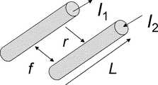
このアクチュエータ1’の動作原理は次の通りである。ジグザグコイル4の並行する各導線は、図4に示したような平行する2本の導線で近似モデル化することができる。図4の平行する2線に、それぞれ電流I1,I2を互いに逆向きに流す。この場合、2本の導線間に働く力は、次式(10)のように表される。ここで、マイナス符号は、2本の導線間に斥力が働くことを表す。The operating principle of this actuator 1 'is as follows. Each parallel conducting wire of the zigzag coil 4 can be approximated by two parallel conducting wires as shown in FIG. Currents I1 and I2 are passed through the two parallel lines in FIG. 4 in opposite directions. In this case, the force acting between the two conductors is expressed as the following equation (10). Here, the minus sign indicates that a repulsive force acts between the two conductors.
ここで、μrは磁性エラストマー2の比透磁率、μ0は真空の透磁率、Lは各導線の長さ、rは2本の導線間の距離である。Here, mur relative permeability of the
従って、図3のアクチュエータ1’のジグザグコイル4に電流を流すと、アクチュエータ1’は伸長することが分かる。 Therefore, it can be seen that the actuator 1 'expands when a current is passed through the zigzag coil 4 of the actuator 1' of FIG.
図5は、本発明の実施例3に係るアクチュエータ5の構成を表す図である。図5(a)は通電していない状態、図5(b)は通電した状態を表している。アクチュエータ5は、導線を螺旋状に巻回した螺旋コイル3と、導線をジグザグに反復して屈曲したジグザグコイル4とが、磁性エラストマー2に並列に埋入されていることを特徴とする。図5では、説明のために磁性エラストマー2を左右2つの部分に分けて記載しているが、実際には磁性エラストマー2は一体に整形される。 FIG. 5 is a diagram illustrating the configuration of the
螺旋コイル3については実施例1と同様のものであり、また、ジグザグコイル4については、実施例2と同様のものである。螺旋コイル3に電流を流すと、実施例1で説明した通り、螺旋コイル3が収縮する。一方、ジグザグコイル4に電流を流すと、実施例2で説明した通り、ジグザグコイル4が伸長する(図6参照)。従って、図5のアクチュエータ5の螺旋コイル3とジグザグコイル4に電流を流した場合、螺旋コイル3の埋入された左側が収縮し、ジグザグコイル4が埋入された右側が伸長するため、結果的に図5(b)に示したように屈曲した動きが生じることになる。 The
図7は、本発明の実施例4に係るアクチュエータ9の構成を表す図である。図7(a)はアクチュエータ9の構成、図7(b)はアクチュエータ9の動作原理を表している。 FIG. 7 is a diagram illustrating the configuration of the
アクチュエータ9は、導線を螺旋状に巻回した螺旋コイルを環状に曲げて形成された2つのトーラスコイル10,11を有する。各トーラスコイル10,11は、トーラス状に整形された磁性エラストマー2に埋入されている。また、トーラスコイル10とトーラスコイル11とは、中心軸が互いに直交するように配置されている。 The
トーラスコイル10,11に電流を流すと、図7(b)に示したように、トーラスコイル10,11は直交する2つの電磁石となる。従って、この2つの電磁石の相互作用によって、トーラスコイル10,11の間には、図7(b)に矢印Fで示したような捻りの力が作用する。すなわち、アクチュエータ9は捻り運動を作り出すことができる。 When a current is passed through the torus coils 10 and 11, the torus coils 10 and 11 become two electromagnets orthogonal to each other as shown in FIG. Therefore, a twisting force as shown by an arrow F in FIG. 7B acts between the torus coils 10 and 11 due to the interaction of the two electromagnets. That is, the
図8は、実施例1,3,4の各アクチュエータの動作を表す図である。実施例1のアクチュエータ1は、図8(a)のような伸縮運動を作り出す。実施例3のアクチュエータ5は、図8(b)のような屈曲運動を作り出す。実施例4のアクチュエータ9は、図8(c)のような捻り運動を作り出す。従って、この3種類のアクチュエータ1,5,9を用いることによって、ソフトアクチュエータに要求されるすべての運動を作り出すことができる。例えば、膝、肘、指などの関節は、筋肉の伸縮運動又は屈曲運動、股関節、肩は屈曲運動と捻り運動、骨格筋肉、心臓、胃などの内臓は伸縮運動のアクチュエータをそれぞれ用いれば、その運動を再現することが可能である。 FIG. 8 is a diagram illustrating the operation of each actuator of the first, third, and fourth embodiments. The
図9は、本発明の実施例5に係るアクチュエータ6を用いた駆動装置7の構成を表す図である。アクチュエータ6は、実施例1のアクチュエータ1を直列に2つ並べた構造を有する。2つのアクチュエータ1は、それぞれ独立に通電することが可能である。このアクチュエータ6を備えた駆動装置7は、2つのアクチュエータ1,1の間に弁8を介設し、2つのアクチュエータ1,1が直管状に接続された構成を有している。 FIG. 9 is a diagram illustrating a configuration of a drive device 7 using the
アクチュエータ1,1に交互に電流を流すことにより、一方が伸び他方が収縮するリニアポンプを構成することができる(図9参照)。図9(a)では、左側のアクチュエータ1(A)が通電状態、右側のアクチュエータ1(B)が非通電状態とされている。この場合、アクチュエータ1(A)が収縮し、アクチュエータ1(B)が伸長する。図9(b)では、左側のアクチュエータ1(A)が非通電状態、右側のアクチュエータ1(B)が通電状態とされている。この場合、アクチュエータ1(B)が収縮し、アクチュエータ1(A)が伸長する。従って、アクチュエータ1(A),1(B)に交互に電流を流すことにより、駆動装置7は、リニアポンプとして機能する。 By alternately supplying current to the
図10は、本発明の実施例6に係るセンサの構成を表す図である。図10において、検出子12を構成する磁性エラストマー2及び螺旋コイル3は、図1と同様のものである。磁性エラストマー2は、粉体状の強磁性体材料又は高透磁率材料をエラストマーに混合して構成されている。検出子12の螺旋コイル3の両端には、螺旋コイル3に発生する電流を検出する検出手段13が接続されている。 FIG. 10 is a diagram illustrating the configuration of a sensor according to Example 6 of the invention. In FIG. 10, the
この構成では、検出子12に圧縮又は伸長する力が加わって、検出子12が圧縮変形又は伸長変形した場合、螺旋コイル3を通過する磁場が変化するため、電磁誘導によって螺旋コイル3に起電力が生じ電流が流れる。この電流を検出手段13が検出することで、検出子12の変形の大きさを検出することができる。 In this configuration, when a force that compresses or expands is applied to the
検出感度を良好にするためには、磁性エラストマー2の材料としては強磁性体材料を混合したものを用いることが好ましい。また、磁性エラストマー2として、強磁性体材料の磁化を一方向に配向させた異方性の磁性エラストマーを使用することがより好ましい。螺旋コイル3を通過する磁束数がより多くできるからである。 In order to improve the detection sensitivity, it is preferable to use a
尚、本実施例では、検出子12として図1のアクチュエータ1と同様の構成のものを使用したが、当然ながら、図3のアクチュエータ1’、図5のアクチュエータ5、図7のアクチュエータ9と同様の構造の検出子を使用することもできる。この場合も、磁性エラストマー2としては、粉体状の強磁性体材料又は高透磁率材料をエラストマーに混合したものを使用する。 In this embodiment, the
アクチュエータ1,1’,5,6,9
磁性エラストマー2
螺旋コイル3
ジグザグコイル4
駆動装置7
弁8
トーラスコイル10,11
検出子12
検出手段13
Zigzag coil 4
Drive device 7
Valve 8
Torus coils 10, 11
Detection means 13
Claims (1)
Translated fromJapaneseそれぞれ独立に通電可能な複数の前記コイルが、管状の前記磁性エラストマーに直列に埋入され直管状に形成されており、前記各コイル間の管内には弁が介設されていることを特徴とするアクチュエータ。A coil that can be energized and embedded in a magnetic elastomer obtained by mixing a ferromagnetic material or a high permeability material in an elastomer,
A plurality of the coils that can be energized independently are embedded in series in thetubular magnetic elastomerand formed in a straight tubular shape, and a valve is interposed in the tube between the coils. Actuator to do.
Priority Applications (4)
| Application Number | Priority Date | Filing Date | Title |
|---|---|---|---|
| JP2007340048AJP5267907B2 (en) | 2007-12-28 | 2007-12-28 | Actuator using magnetic force, driving device using the same, and sensor |
| US12/808,316US8338993B2 (en) | 2007-12-28 | 2008-12-08 | Actuator using magnetic force, and drive device and sensor using the same |
| EP08868733AEP2239837A4 (en) | 2007-12-28 | 2008-12-08 | ACTUATOR USING MAGNETIC FORCE, AND DRIVING DEVICE AND SENSOR USING THE SAME |
| PCT/JP2008/072249WO2009084378A1 (en) | 2007-12-28 | 2008-12-08 | Actuator using magnetic force, and drive device and sensor using the same |
Applications Claiming Priority (1)
| Application Number | Priority Date | Filing Date | Title |
|---|---|---|---|
| JP2007340048AJP5267907B2 (en) | 2007-12-28 | 2007-12-28 | Actuator using magnetic force, driving device using the same, and sensor |
Publications (2)
| Publication Number | Publication Date |
|---|---|
| JP2009165219A JP2009165219A (en) | 2009-07-23 |
| JP5267907B2true JP5267907B2 (en) | 2013-08-21 |
Family
ID=40824099
Family Applications (1)
| Application Number | Title | Priority Date | Filing Date |
|---|---|---|---|
| JP2007340048AExpired - Fee RelatedJP5267907B2 (en) | 2007-12-28 | 2007-12-28 | Actuator using magnetic force, driving device using the same, and sensor |
Country Status (4)
| Country | Link |
|---|---|
| US (1) | US8338993B2 (en) |
| EP (1) | EP2239837A4 (en) |
| JP (1) | JP5267907B2 (en) |
| WO (1) | WO2009084378A1 (en) |
Families Citing this family (23)
| Publication number | Priority date | Publication date | Assignee | Title |
|---|---|---|---|---|
| JP6017107B2 (en) | 2009-12-28 | 2016-10-26 | ソニー株式会社 | Image sensor, manufacturing method thereof, and sensor device |
| JP2012125136A (en)* | 2010-11-18 | 2012-06-28 | Panasonic Corp | Magnetic response type actuator |
| US9211122B2 (en) | 2011-03-14 | 2015-12-15 | Ethicon Endo-Surgery, Inc. | Surgical access devices with anvil introduction and specimen retrieval structures |
| JP2013108428A (en)* | 2011-11-21 | 2013-06-06 | Toyota Motor Corp | Valve gear for internal combustion engine |
| US20140021936A1 (en)* | 2012-07-20 | 2014-01-23 | Dan Tho Lu | High efficiency energy harvester and methods thereof |
| US9528532B2 (en) | 2012-09-27 | 2016-12-27 | William Davis Simmons | Hydraulic actuator |
| DE102014222832A1 (en)* | 2014-11-10 | 2016-05-12 | Fraunhofer-Gesellschaft zur Förderung der angewandten Forschung e.V. | Linear actuator and its use |
| JP2017046462A (en)* | 2015-08-26 | 2017-03-02 | セイコーエプソン株式会社 | Armature, field magneton, manufacturing method for armature, manufacturing method for field magneton and electric machine |
| CN109310420A (en)* | 2016-04-01 | 2019-02-05 | 伊西康有限责任公司 | Including can profiled shaft surgical stapling system |
| US10420552B2 (en) | 2016-04-01 | 2019-09-24 | Ethicon Llc | Surgical stapling system configured to provide selective cutting of tissue |
| US10413297B2 (en) | 2016-04-01 | 2019-09-17 | Ethicon Llc | Surgical stapling system configured to apply annular rows of staples having different heights |
| US11284890B2 (en) | 2016-04-01 | 2022-03-29 | Cilag Gmbh International | Circular stapling system comprising an incisable tissue support |
| US10531874B2 (en) | 2016-04-01 | 2020-01-14 | Ethicon Llc | Surgical cutting and stapling end effector with anvil concentric drive member |
| JP7010838B2 (en) | 2016-04-01 | 2022-01-26 | エシコン エルエルシー | Surgical staple fasteners |
| WO2018130295A1 (en)* | 2017-01-13 | 2018-07-19 | MAX-PLANCK-Gesellschaft zur Förderung der Wissenschaften e.V. | Method of actuating a shape changeable member, shape changeable member and actuating system |
| JP7615446B2 (en)* | 2017-07-12 | 2025-01-17 | 株式会社Kri | Power generation device, method for producing magnetic hard viscoelastic material, and method for using the power generation device |
| US11448103B2 (en)* | 2018-06-28 | 2022-09-20 | Board Of Regents, The University Of Texas System | Electromagnetic soft actuators |
| WO2020042912A1 (en)* | 2018-08-31 | 2020-03-05 | 浙江盘毂动力科技有限公司 | Segment core and axial flux motor |
| US11103324B2 (en)* | 2019-08-28 | 2021-08-31 | Massachusetts Institute Of Technology | Magnetically steerable continuum robotic guidewires for neurovascular applications |
| CN111371341B (en)* | 2020-03-24 | 2021-04-30 | 燕山大学 | Micro-small SMA movable tooth transmission motor |
| CN111520381B (en)* | 2020-04-30 | 2022-01-18 | 广东电网有限责任公司东莞供电局 | Bolt assembly and primary equipment |
| CN112318539A (en)* | 2020-11-13 | 2021-02-05 | 电子科技大学 | An integrated bionic finger device based on near-field interaction for stacked coil motion sensing |
| CN114415249A (en)* | 2022-01-19 | 2022-04-29 | 华中科技大学 | Active retractable magnetoelectric sensor and preparation method thereof, and magnetoelectric sensor array |
Family Cites Families (32)
| Publication number | Priority date | Publication date | Assignee | Title |
|---|---|---|---|---|
| US2532876A (en)* | 1946-12-19 | 1950-12-05 | Asche Robert | Electromagnetic artificial muscle |
| US4176411A (en)* | 1977-11-28 | 1979-12-04 | Runge Thomas M | Cardiac assist device employing electrically stimulated artificial muscle |
| JPS59144474A (en)* | 1983-01-31 | 1984-08-18 | ト−マス・ジエイ・グリア−・ジユニア | Motion element for face movable manekin |
| US5090248A (en)* | 1989-01-23 | 1992-02-25 | The University Of Melbourne | Electronic transducer |
| JPH03293980A (en)* | 1990-04-10 | 1991-12-25 | Seiko Epson Corp | magnetostrictive actuator |
| US5087804A (en)* | 1990-12-28 | 1992-02-11 | Metcal, Inc. | Self-regulating heater with integral induction coil and method of manufacture thereof |
| JP2768869B2 (en) | 1992-06-03 | 1998-06-25 | 工業技術院長 | Actuator element |
| JPH0783159A (en)* | 1993-09-20 | 1995-03-28 | Olympus Optical Co Ltd | Mechano-chemical actuator |
| JP3293980B2 (en) | 1993-11-15 | 2002-06-17 | 大日本印刷株式会社 | Offset printing equipment |
| WO1997027822A1 (en)* | 1996-01-30 | 1997-08-07 | John Chilver | Artificial muscle |
| US5977685A (en)* | 1996-02-15 | 1999-11-02 | Nitta Corporation | Polyurethane elastomer actuator |
| US6781284B1 (en)* | 1997-02-07 | 2004-08-24 | Sri International | Electroactive polymer transducers and actuators |
| JPH11169394A (en) | 1997-12-15 | 1999-06-29 | Keiichi Kanefuji | Artificial muscle body having metal electrode on surface thereof |
| JPH11169393A (en) | 1997-12-15 | 1999-06-29 | Keiichi Kanefuji | Artificial muscle body |
| JP2000020175A (en)* | 1998-06-26 | 2000-01-21 | Toshiba Corp | Electronics |
| US7518284B2 (en)* | 2000-11-02 | 2009-04-14 | Danfoss A/S | Dielectric composite and a method of manufacturing a dielectric composite |
| US7233097B2 (en) | 2001-05-22 | 2007-06-19 | Sri International | Rolled electroactive polymers |
| US20040126565A1 (en)* | 2002-05-09 | 2004-07-01 | Ganapathy Naganathan | Actively controlled impact elements |
| JP4168325B2 (en)* | 2002-12-10 | 2008-10-22 | ソニー株式会社 | Polymer actuator |
| DE602004029989D1 (en)* | 2003-03-03 | 2010-12-23 | Stanford Res Inst Int | INVOLVED ELECTROACTIVE POLYMERS |
| ITBO20030678A1 (en)* | 2003-11-14 | 2005-05-15 | Magneti Marelli Powertrain Spa | FUEL INJECTOR WITH HYDRAULIC IMPLEMENTATION OF THE PIN |
| JP3811495B2 (en)* | 2004-02-05 | 2006-08-23 | 松下電器産業株式会社 | Actuator and method of manufacturing flat electrode support for actuator |
| DE102004034723A1 (en)* | 2004-07-17 | 2006-02-09 | Carl Freudenberg Kg | Magnetostrictive element and its use |
| US7140478B2 (en)* | 2004-08-13 | 2006-11-28 | General Motors Corporation | Reversibly expandable energy absorbing assembly utilizing actively controlled and engineered materials for impact management and methods for operating the same |
| JP4831994B2 (en) | 2005-04-18 | 2011-12-07 | イーメックス株式会社 | Microfluidic transport pump and conductive polymer actuator element |
| FR2891917B1 (en)* | 2005-10-07 | 2008-01-11 | Billanco | MAGNETIC FIELD AND CURRENT SENSORS, CONTROL METHOD AND MAGNETIC CORE FOR THESE SENSORS |
| JP2007138721A (en) | 2005-11-15 | 2007-06-07 | Ask:Kk | Linear drive actuator |
| JP4965116B2 (en)* | 2005-12-07 | 2012-07-04 | スミダコーポレーション株式会社 | Flexible coil |
| JP4736879B2 (en) | 2006-03-17 | 2011-07-27 | コニカミノルタオプト株式会社 | Actuator drive |
| JP5045877B2 (en) | 2006-03-28 | 2012-10-10 | ソニー株式会社 | Polymer actuator |
| JP5114722B2 (en) | 2006-05-29 | 2013-01-09 | 独立行政法人理化学研究所 | Integrated soft actuator with sensor function |
| US7498682B2 (en)* | 2007-03-07 | 2009-03-03 | Aaron Patrick Lemieux | Electrical energy generator |
- 2007
- 2007-12-28JPJP2007340048Apatent/JP5267907B2/ennot_activeExpired - Fee Related
- 2008
- 2008-12-08USUS12/808,316patent/US8338993B2/ennot_activeExpired - Fee Related
- 2008-12-08WOPCT/JP2008/072249patent/WO2009084378A1/enactiveApplication Filing
- 2008-12-08EPEP08868733Apatent/EP2239837A4/ennot_activeWithdrawn
Also Published As
| Publication number | Publication date |
|---|---|
| US8338993B2 (en) | 2012-12-25 |
| WO2009084378A1 (en) | 2009-07-09 |
| EP2239837A1 (en) | 2010-10-13 |
| US20100277011A1 (en) | 2010-11-04 |
| JP2009165219A (en) | 2009-07-23 |
| EP2239837A4 (en) | 2013-03-27 |
Similar Documents
| Publication | Publication Date | Title |
|---|---|---|
| JP5267907B2 (en) | Actuator using magnetic force, driving device using the same, and sensor | |
| CN107380290B (en) | A kind of software climbing robot of electromagnetic drive | |
| CN103384957B (en) | Mechanisms used, for example, to generate wave-like motion for propulsion and for harnessing the energy of a moving fluid | |
| Ebrahimi et al. | Design optimization of a solenoid-based electromagnetic soft actuator with permanent magnet core | |
| Song et al. | Bioinspired segment robot with earthworm-like plane locomotion | |
| CN109564818B (en) | Magnetic Field Control System | |
| CN101976932B (en) | Inchworm motion linear electric motor based on electromagnetic clamping mechanism | |
| CN102945726B (en) | Based on flexible drive device that magnetic and electromagnet interact and combinations thereof | |
| CN108127658B (en) | An artificial muscle powered by electromagnetic force | |
| KR20230075262A (en) | Artficial muscle using electromagnet | |
| Kim et al. | Microrobots for a capsule endoscope | |
| Shin et al. | An earthworm-like actuator using segmented solenoids | |
| Kohls et al. | Soft electromagnetic motor and soft magnetic sensors for synchronous rotary motion | |
| JP2015154681A (en) | Power generation apparatus and method, and electronic apparatus | |
| Takai et al. | Prototyping the flexible solenoid-coil artificial muscle, for exoskeletal robots | |
| CN211555939U (en) | Dielectric elastomer actuator and driving device | |
| CN111129283A (en) | Driving device, dielectric elastomer actuator and manufacturing method thereof | |
| Yu et al. | A novel in-pipe worming robot based on SMA | |
| Kim et al. | Methodology of dynamic actuation for flexible magnetic actuator and biomimetic robotics application | |
| US11448103B2 (en) | Electromagnetic soft actuators | |
| KR19990065579A (en) | Multilayer induction motor module using human muscle characteristics | |
| Woehrmann et al. | Design of a fully actuated electromagnetic bending actuator for endoscopic applications | |
| CN107486853B (en) | A kind of electromagnetic type bionic muscle | |
| JP2007296612A (en) | Electromagnetic actuator and electromagnetic actuator device | |
| Cortez et al. | Electromagnetic artificial muscle technologies revisited: Basis for the design of magnetic coupled artificial exoskeletal muscle |
Legal Events
| Date | Code | Title | Description |
|---|---|---|---|
| A621 | Written request for application examination | Free format text:JAPANESE INTERMEDIATE CODE: A621 Effective date:20101027 | |
| A131 | Notification of reasons for refusal | Free format text:JAPANESE INTERMEDIATE CODE: A131 Effective date:20120808 | |
| A521 | Request for written amendment filed | Free format text:JAPANESE INTERMEDIATE CODE: A523 Effective date:20120920 | |
| TRDD | Decision of grant or rejection written | ||
| A01 | Written decision to grant a patent or to grant a registration (utility model) | Free format text:JAPANESE INTERMEDIATE CODE: A01 Effective date:20130403 | |
| A61 | First payment of annual fees (during grant procedure) | Free format text:JAPANESE INTERMEDIATE CODE: A61 Effective date:20130425 | |
| R150 | Certificate of patent or registration of utility model | Free format text:JAPANESE INTERMEDIATE CODE: R150 Ref document number:5267907 Country of ref document:JP Free format text:JAPANESE INTERMEDIATE CODE: R150 | |
| R250 | Receipt of annual fees | Free format text:JAPANESE INTERMEDIATE CODE: R250 | |
| S111 | Request for change of ownership or part of ownership | Free format text:JAPANESE INTERMEDIATE CODE: R313113 | |
| R350 | Written notification of registration of transfer | Free format text:JAPANESE INTERMEDIATE CODE: R350 | |
| LAPS | Cancellation because of no payment of annual fees |