JP5267300B2 - Starter - Google Patents
StarterDownload PDFInfo
- Publication number
- JP5267300B2 JP5267300B2JP2009098920AJP2009098920AJP5267300B2JP 5267300 B2JP5267300 B2JP 5267300B2JP 2009098920 AJP2009098920 AJP 2009098920AJP 2009098920 AJP2009098920 AJP 2009098920AJP 5267300 B2JP5267300 B2JP 5267300B2
- Authority
- JP
- Japan
- Prior art keywords
- yoke
- switch
- motor
- solenoid
- pinion
- Prior art date
- Legal status (The legal status is an assumption and is not a legal conclusion. Google has not performed a legal analysis and makes no representation as to the accuracy of the status listed.)
- Active
Links
Images


Classifications
- F—MECHANICAL ENGINEERING; LIGHTING; HEATING; WEAPONS; BLASTING
- F02—COMBUSTION ENGINES; HOT-GAS OR COMBUSTION-PRODUCT ENGINE PLANTS
- F02N—STARTING OF COMBUSTION ENGINES; STARTING AIDS FOR SUCH ENGINES, NOT OTHERWISE PROVIDED FOR
- F02N15/00—Other power-operated starting apparatus; Component parts, details, or accessories, not provided for in, or of interest apart from groups F02N5/00 - F02N13/00
- F02N15/02—Gearing between starting-engines and started engines; Engagement or disengagement thereof
- F02N15/04—Gearing between starting-engines and started engines; Engagement or disengagement thereof the gearing including disengaging toothed gears
- F02N15/06—Gearing between starting-engines and started engines; Engagement or disengagement thereof the gearing including disengaging toothed gears the toothed gears being moved by axial displacement
- F02N15/067—Gearing between starting-engines and started engines; Engagement or disengagement thereof the gearing including disengaging toothed gears the toothed gears being moved by axial displacement the starter comprising an electro-magnetically actuated lever
- F—MECHANICAL ENGINEERING; LIGHTING; HEATING; WEAPONS; BLASTING
- F02—COMBUSTION ENGINES; HOT-GAS OR COMBUSTION-PRODUCT ENGINE PLANTS
- F02N—STARTING OF COMBUSTION ENGINES; STARTING AIDS FOR SUCH ENGINES, NOT OTHERWISE PROVIDED FOR
- F02N11/00—Starting of engines by means of electric motors
- F02N11/08—Circuits specially adapted for starting of engines
- F02N11/087—Details of the switching means in starting circuits, e.g. relays or electronic switches
- H—ELECTRICITY
- H01—ELECTRIC ELEMENTS
- H01H—ELECTRIC SWITCHES; RELAYS; SELECTORS; EMERGENCY PROTECTIVE DEVICES
- H01H51/00—Electromagnetic relays
- H01H51/02—Non-polarised relays
- H01H51/04—Non-polarised relays with single armature; with single set of ganged armatures
- H01H51/06—Armature is movable between two limit positions of rest and is moved in one direction due to energisation of an electromagnet and after the electromagnet is de-energised is returned by energy stored during the movement in the first direction, e.g. by using a spring, by using a permanent magnet, by gravity
- H01H51/065—Relays having a pair of normally open contacts rigidly fixed to a magnetic core movable along the axis of a solenoid, e.g. relays for starting automobiles
- F—MECHANICAL ENGINEERING; LIGHTING; HEATING; WEAPONS; BLASTING
- F02—COMBUSTION ENGINES; HOT-GAS OR COMBUSTION-PRODUCT ENGINE PLANTS
- F02N—STARTING OF COMBUSTION ENGINES; STARTING AIDS FOR SUCH ENGINES, NOT OTHERWISE PROVIDED FOR
- F02N11/00—Starting of engines by means of electric motors
- F02N11/08—Circuits specially adapted for starting of engines
- F02N11/0814—Circuits specially adapted for starting of engines comprising means for controlling automatic idle-start-stop
Landscapes
- Engineering & Computer Science (AREA)
- Physics & Mathematics (AREA)
- Electromagnetism (AREA)
- Chemical & Material Sciences (AREA)
- Combustion & Propulsion (AREA)
- Mechanical Engineering (AREA)
- General Engineering & Computer Science (AREA)
- Connection Of Motors, Electrical Generators, Mechanical Devices, And The Like (AREA)
Description
Translated fromJapanese本発明は、ピニオンギヤをリングギヤ側へ押し出すためのピニオン押出し用ソレノイドと、モータの通電電流をオン/オフするためのモータ通電用スイッチとを備えたスタータに関する。 The present invention relates to a starter provided with a pinion pushing solenoid for pushing a pinion gear toward a ring gear and a motor energization switch for turning on / off the energization current of the motor.
近年、二酸化炭素の削減および燃費向上を目的として、エンジンの停止および再始動を自動制御するエンジン自動停止/再始動装置(以下、アイドルストップ装置と呼ぶ)を搭載する車両が増加するものと予測されている。このアイドルストップ装置は、車両が停止した状態(アイドリング状態)、あるいは、エンジンの減速期間中に所定の停止条件が成立すると、エンジンへの燃料供給をカットしてエンジンを自動的に停止させ、その後、ユーザにより発進操作(例えば、ブレーキの解除操作、ドライブレンジへのシフト操作等)が行われて始動条件が成立すると、スタータを自動的に作動させてエンジンを再始動するシステムである。 In recent years, for the purpose of reducing carbon dioxide and improving fuel efficiency, it is predicted that the number of vehicles equipped with an engine automatic stop / restart device (hereinafter referred to as an idle stop device) that automatically controls engine stop and restart will increase. ing. This idle stop device cuts off the fuel supply to the engine and automatically stops the engine when the vehicle is stopped (idling state) or when a predetermined stop condition is satisfied during the engine deceleration period. In this system, when a start operation is performed by the user (for example, a brake release operation, a shift operation to a drive range, etc.) and a start condition is satisfied, the starter is automatically operated to restart the engine.
このアイドルストップ装置は、例えば、交差点での信号停止や、渋滞により一時停止する場合等の様に、道路上でエンジンを自動停止させる機会が多いため、始動条件が成立した時には、出来るだけ速やかに、且つ、確実にエンジンを再始動させることが要求される。そこで、スタータとしては、ピニオンギヤを押し出すための機能と、モータの通電電流をオン/オフする機能とを分離する必要が出てきた。これを実現できる従来技術として、特許文献1に記載されたスタータがある。このスタータは、シフトレバーを介してピニオンギヤをリングギヤ側へ押し出すための駆動力(電磁石の吸引力)を発生するピニオン押出し用ソレノイドと、モータの通電電流をオン/オフするためのモータ通電用スイッチとを備え、両者を分離して別体に構成している。 This idle stop device has many opportunities to automatically stop the engine on the road, such as when stopping at traffic lights at intersections or when it stops temporarily due to traffic jams. And it is required to restart the engine reliably. Therefore, it has become necessary for the starter to separate the function for pushing out the pinion gear from the function for turning on / off the energization current of the motor. As a prior art capable of realizing this, there is a starter described in Patent Document 1. This starter includes a pinion push-out solenoid that generates a driving force (electromagnetic attraction force) for pushing the pinion gear toward the ring gear via a shift lever, a motor energization switch for turning on / off the energization current of the motor, The two are separated and configured separately.
ところで、エンジンルーム内におけるスタータの搭載位置は、通常、エンジンの横に密接した部位であるが、多くの場合、エンジンの周囲には、吸気管を初めとするエンジン性能にとって優先度の高い機能部品が配置される。このため、エンジンの始動だけに使用されるスタータは、その外径寸法の制約を大きく受ける場合が多く、製品自体の市場競争力を確保するためには、小型化による搭載性向上が重要である。
しかし、特許文献1に記載されたスタータは、ピニオン押出し用ソレノイドとモータ通電用スイッチとが並列的に配設されている。つまり、ピニオン押出し用ソレノイドとモータ通電用スイッチがモータの周方向で異なる位置に配置されている。By the way, the position where the starter is mounted in the engine room is usually a part close to the side of the engine, but in many cases, there are functional parts around the engine that have a high priority for engine performance including the intake pipe. Is placed. For this reason, starters that are used only for starting the engine are often greatly restricted by the outer diameter, and in order to ensure the market competitiveness of the product itself, it is important to improve mountability through downsizing. .
However, in the starter described in Patent Document 1, a pinion pushing solenoid and a motor energizing switch are arranged in parallel. That is, the pinion pushing solenoid and the motor energizing switch are arranged at different positions in the circumferential direction of the motor.
上記の構成では、モータの径方向外側で二方向に寸法が増加するため、エンジンの周囲に近接して配置される機能部品との干渉を回避することは困難であり、搭載面で大きな寸法上のデメリットを生じる。
また、特許文献1に示されるピニオン押出し用ソレノイドとモータ通電用スイッチは、両者を完全に分離して別体に構成しているため、両者の間で部品を共通化することが出来ない。このため、従来のスタータ用電磁スイッチと比較すると、部品点数が多くなる問題がある。さらに、ピニオン押出し用ソレノイドおよびモータ通電用スイッチをそれぞれ組み立てる際に、ソレノイドヨークおよびスイッチヨークの端部をかしめる工程が必要である。この場合、ヨークの端部にかしめ部を設けるために、ヨークの内周面を切削して薄肉に加工する必要があるため、作業工数が多くなり、作業性も良くない。In the above configuration, since the dimensions increase in two directions on the outer side in the radial direction of the motor, it is difficult to avoid interference with the functional components arranged in the vicinity of the engine. Cause the disadvantages.
Moreover, since the pinion pushing solenoid and the motor energizing switch shown in Patent Document 1 are separated from each other and configured separately, it is not possible to share parts between them. For this reason, compared with the conventional electromagnetic switch for starters, there exists a problem that a number of parts increases. Furthermore, when assembling the pinion push-out solenoid and the motor energization switch, respectively, a step of caulking the end portions of the solenoid yoke and the switch yoke is necessary. In this case, in order to provide the crimped portion at the end of the yoke, it is necessary to cut the inner peripheral surface of the yoke to make it thin, so that the number of work steps increases and the workability is not good.
本発明は、上記事情に基づいて成されたもので、その目的は、ピニオンギヤを軸方向に押し出す機能を有するピニオン押出し用ソレノイドと、モータの通電電流をオン/オフする機能を有するモータ通電用スイッチを備え、両者の作動を個々に独立して制御できるスタータであって、車両への搭載性を向上でき、且つ、部品点数の低減を図ると共に、作業性を改善できるスタータを提供することにある。 The present invention has been made based on the above circumstances, and its object is to provide a pinion pushing solenoid having a function of pushing out a pinion gear in the axial direction, and a motor energizing switch having a function of turning on / off the energizing current of the motor. It is an object to provide a starter capable of independently controlling the operation of the two, capable of improving the mounting property on a vehicle, reducing the number of parts, and improving workability. .
(請求項1の発明)
本発明は、通電により回転力を発生するモータと、このモータの回転力が伝達されて回転する出力軸と、モータの回転力をエンジンのリングギヤに伝達するためのピニオンギヤを有し、このピニオンギヤと一体に出力軸の外周上を軸方向に移動可能に設けられたピニオン移動体と、ソレノイドコイルへの通電によって電磁石を形成し、この電磁石の吸引力を利用してピニオン移動体を軸方向に押し出す働きを有するピニオン押出し用ソレノイドと、スイッチコイルへの通電によって電磁石を形成し、この電磁石の吸引力を利用してモータの通電電流をオン/オフするモータ通電用スイッチとを備え、ピニオン押出し用ソレノイドの作動とモータ通電用スイッチの作動を個々に独立して制御できるスタータであって、ピニオン押出し用ソレノイドとモータ通電用スイッチは、両者が軸方向に直列に配設されて、ソレノイドコイルとスイッチコイルとの間に、両者に共通の固定鉄心を配置すると共に、ピニオン押出し用ソレノイドの外周を覆うソレノイドヨークと、モータ通電用スイッチの外周を覆うスイッチヨークとが軸方向に連続して形成され、一つの全体ヨークとして一体に設けられていることを特徴とする。(Invention of Claim 1)
The present invention has a motor that generates a rotational force by energization, an output shaft that rotates by transmitting the rotational force of the motor, and a pinion gear for transmitting the rotational force of the motor to an engine ring gear. An electromagnet is formed by energizing the solenoid coil and a pinion moving body that is integrally movable on the outer periphery of the output shaft, and pushes the pinion moving body in the axial direction using the attractive force of the electromagnet. A pinion push-out solenoid having a functioning pinion push-out solenoid and a motor energization switch that forms an electromagnet by energizing the switch coil and turns on / off the motor energizing current using the attraction force of the electromagnet Starter that can control the operation of the motor and the switch for energizing the motor independently, And the motor energization switch are both arranged in series in the axial direction, and a common fixed iron core is disposed between the solenoid coil and the switch coil, and the solenoid yoke that covers the outer periphery of the pinion extrusion solenoid And a switch yoke covering the outer periphery of the motor energization switch is formed continuously in the axial direction, and is integrally provided as one whole yoke.
本発明のスタータは、ピニオン押出し用ソレノイドとモータ通電用スイッチとを軸方向に直列に配設しているので、モータの径方向外側で二方向に寸法が増加することはない。これにより、ピニオン押出し用ソレノイドとモータ通電用スイッチとをモータの周方向で異なる位置に配置した特許文献1のスタータと比較して、搭載面での寸法上の制約を小さくできるので、車両への搭載性が向上する。言い換えると、ピニオンギヤを押し出す働きと、モータの通電電流をオン/オフする働きとを一つの電磁スイッチで行う従来のスタータと同等の搭載性を確保できる。
また、ピニオン押出し用ソレノイドとモータ通電用スイッチは、ソレノイドコイルとスイッチコイルとの間に、両者に共通の固定鉄心を配置すると共に、ソレノイドヨークとスイッチヨークが一つの全体ヨークとして一体に設けられている。これにより、ピニオン押出し用ソレノイドとモータ通電用スイッチとを別体に構成した場合と比較して、部品点数を減らすことが出来、組み立て工数を低減できる。In the starter of the present invention, the pinion pushing solenoid and the motor energizing switch are arranged in series in the axial direction, so that the dimension does not increase in two directions outside the motor in the radial direction. Thereby, compared with the starter of Patent Document 1 in which the pinion push-out solenoid and the motor energization switch are arranged at different positions in the circumferential direction of the motor, the dimensional constraints on the mounting surface can be reduced. Mountability is improved. In other words, it is possible to ensure the same mountability as that of a conventional starter in which the function of pushing out the pinion gear and the function of turning on / off the energization current of the motor with a single electromagnetic switch.
In addition, the pinion push-out solenoid and the motor energizing switch have a common fixed iron core disposed between the solenoid coil and the switch coil, and the solenoid yoke and the switch yoke are integrally provided as one whole yoke. Yes. Thereby, compared with the case where the pinion pushing solenoid and the motor energizing switch are configured separately, the number of parts can be reduced, and the number of assembly steps can be reduced.
(請求項2の発明)
請求項1に記載したスタータにおいて、全体ヨークは、軸方向一端側の端部に円環状の底面を有し、他端側の端部が開口する有底の筒形状であり、軸方向の一端から他端まで外径が同一寸法を有し、且つ、ソレノイドヨークを形成する軸方向一端側より、スイッチヨークを形成する軸方向他端側の方が薄肉に設けられ、モータ通電用スイッチは、モータの通電回路に接続される2本の端子ボルトを固定する樹脂カバーを有し、この樹脂カバーが、全体ヨークの薄肉に設けられた他端側の開口端部にかしめ固定されていることを特徴とする。(Invention of Claim 2)
2. The starter according to claim 1, wherein the entire yoke has a cylindrical shape with a bottom having an annular bottom at an end on one end side in the axial direction, and an end on the other end side is opened. The outer diameter has the same dimension from the other end to the other end, and the other end in the axial direction forming the switch yoke is thinner than the one end in the axial direction forming the solenoid yoke. It has a resin cover that fixes two terminal bolts connected to the energization circuit of the motor, and this resin cover is caulked and fixed to the open end of the other end provided on the thin wall of the entire yoke. Features.
本発明のピニオン押出し用ソレノイドとモータ通電用スイッチは、ソレノイドヨークとスイッチヨークが一つの全体ヨークとして一体に設けられているので、ソレノイドヨークとスイッチヨークを個別にかしめる必要はなく、薄肉に設けられた全体ヨークの開口端部をかしめるだけで樹脂カバーを固定できる。これにより、ソレノイドヨークとスイッチヨークを個別にかしめる場合と比較すると、ヨークの端部にかしめ部を設けるために、ヨークの内周面を切削して薄肉に加工する工程を減らすことができ、且つ、かしめ工程も少なくできるので、作業工程の低減により、作業性の改善を図ることが出来る。 Since the solenoid yoke and the switch yoke are integrally provided as one whole yoke, the pinion push-out solenoid and the motor energizing switch according to the present invention do not need to be separately caulked and are provided thinly. The resin cover can be fixed simply by caulking the open end of the entire yoke. Thereby, compared with the case where the solenoid yoke and the switch yoke are caulked separately, in order to provide the caulking portion at the end of the yoke, the process of cutting the inner peripheral surface of the yoke to make it thin can be reduced. In addition, since the caulking process can be reduced, the workability can be improved by reducing the work process.
(請求項3の発明)
請求項2に記載したスタータにおいて、全体ヨークの薄肉に設けられた軸方向他端側の内周には、スイッチコイルの径方向外周側に磁路の一部を形成する円筒状の磁路形成部材が配置されていることを特徴とする。
本発明の全体ヨークは、スイッチヨークを形成する軸方向他端側の肉厚が、ソレノイドヨークを形成する軸方向一端側の肉厚より薄く形成されるが、薄肉に設けられた軸方向他端側の内周に円筒状の磁路形成部材を配置することにより、スイッチコイルの径方向外周側に形成される磁路の断面積を大きく出来るので、磁気飽和によるモータ通電用スイッチの性能低下を防止でき、好適な性能を得ることができる。(Invention of Claim 3)
3. A starter according to
The overall yoke of the present invention is formed such that the thickness at the other end in the axial direction forming the switch yoke is thinner than the thickness at one end in the axial direction forming the solenoid yoke. By disposing a cylindrical magnetic path forming member on the inner periphery of the side, the cross-sectional area of the magnetic path formed on the radially outer peripheral side of the switch coil can be increased. It can prevent and can obtain suitable performance.
(請求項4の発明)
請求項2または3に記載したスタータにおいて、全体ヨークの内周面には、ソレノイドヨークを形成する軸方向一端側と、スイッチヨークを形成する軸方向他端側との間に段差を有し、固定鉄心は、全体ヨークの他端側に開口する開口端からスイッチヨークを形成する軸方向他端側の内部に挿入され、軸方向一端側の外周端面が段差に当接して軸方向に位置決めされることを特徴とする。
上記の構成によれば、全体ヨークの内周面に形成される段差を利用して固定鉄心を軸方向に位置決めできるので、ピニオン押出し用ソレノイドに使用される各部品およびモータ通電用スイッチに使用される各部品を精度良く組み付けることができる。(Invention of Claim 4)
In the starter according to
According to the above configuration, the fixed iron core can be positioned in the axial direction by using the step formed on the inner peripheral surface of the entire yoke, so that it is used for each component used for the pinion extrusion solenoid and the motor energization switch. Can be assembled with high accuracy.
本発明を実施するための形態を以下の実施例により詳細に説明する。 The mode for carrying out the present invention will be described in detail with reference to the following examples.
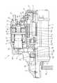
本実施例のスタータ1は、エンジンの停止および再始動を自動制御するアイドルストップ装置に適用できる。このスタータ1は、図1に示す様に、回転力を発生するモータ2と、このモータ2の回転力が伝達されて回転する出力軸3と、この出力軸3の外周上を軸方向に移動可能に設けられたピニオン移動体(後述する)と、シフトレバー4を介してピニオン移動体を反モータ方向(図1の左方向)へ押し出す働きを有するピニオン押出し用ソレノイド5と、バッテリ6(図3参照)からモータ2に電流を流すためのモータ回路に設けられるモータ接点を開閉するモータ通電用スイッチ7等より構成される。 The starter 1 of this embodiment can be applied to an idle stop device that automatically controls stop and restart of the engine. As shown in FIG. 1, the starter 1 includes a
モータ2は、ヨーク8の内周に複数の永久磁石9を配置して構成される界磁と、電機子軸10aの一方の端部に整流子11を設けた電機子10と、整流子11の外周面(整流子面と呼ぶ)に当接して配置され、且つ、ブラシスプリング12によって整流子面に押圧されるブラシ13等を備える整流子電動機である。なお、モータ2の界磁は、永久磁石9の代わりに、界磁コイルによる電磁石界磁を用いることも出来る。
出力軸3は、減速装置14を介して電機子軸10aと同一軸線上に配置され、モータ2の回転が減速装置14で減速されて伝達される。
減速装置14は、周知の遊星歯車減速装置であり、遊星歯車14aの公転運動を拾う遊星キャリア14bが出力軸3と一体に設けられている。The
The
The
ピニオン移動体は、クラッチ15とピニオンギヤ16とで構成される。
クラッチ15は、出力軸3の外周にヘリカルスプライン嵌合するスプラインバレル15aと、このスプラインバレル15aと一体に設けられるアウタ15bと、このアウタ15bの内周に相対回転自在に配置されるインナ15cと、アウタ15bとインナ15cとの間で回転力の伝達を断続するローラ15d等より構成され、そのローラ15dを介してアウタ15bからインナ15cへの一方向のみ回転力を伝達する周知の一方向クラッチとして設けられている。
ピニオンギヤ16は、クラッチ15のインナ15cと一体に設けられ、出力軸3の外周に軸受17を介して相対回転自在に支持されている。The pinion moving body includes a clutch 15 and a
The clutch 15 includes a
The
ピニオン押出し用ソレノイド5とモータ通電用スイッチ7は、それぞれ通電によって電磁石を形成するソレノイドコイル18とスイッチコイル19を有し、このソレノイドコイル18とスイッチコイル19との間に、両者に共通して用いられる固定鉄心20を配置すると共に、ピニオン押出し用ソレノイド5の外周を覆うソレノイドヨーク21と、モータ通電用スイッチ7の外周を覆うスイッチヨーク22とが軸方向に連続して形成され、一つの全体ヨークとして一体に設けられている。すなわち、ピニオン押出し用ソレノイド5とモータ通電用スイッチ7は、図1に示す様に、両者が軸方向に直列に配設されて一体に構成され、モータ2と並列にスタータハウジング23に固定されている。 The pinion push-out
全体ヨークは、図2に示す様に、軸方向一端側(図示左側)の端部に円環状の底面を有し、他端側の端部が開口する有底の筒形状であり、軸方向の一端から他端まで外径が同一寸法を有し、且つ、ソレノイドヨーク21を形成する軸方向一端側より、スイッチヨーク22を形成する軸方向他端側の方が肉径が大きく、肉厚が薄く設けられている。つまり、全体ヨークの内周面には、ソレノイドヨーク21を形成する軸方向一端側と、スイッチヨーク22を形成する軸方向他端側との間に段差21aが設けられている。
固定鉄心20は、全体ヨークの他端側に開口する開口端(スイッチヨーク22の開口端)からスイッチヨーク22を形成する軸方向他端側の内部に挿入され、軸方向一端側の外周端面が、全体ヨークの内周面に設けられる段差21aに当接して軸方向に位置決めされる。As shown in FIG. 2, the entire yoke has a cylindrical shape with a bottom having an annular bottom at the end on one end side (left side in the figure) and an end on the other end opening. The outer diameter has the same dimension from one end to the other end, and the axial other end side forming the
The fixed
以下、全体ヨーク(ソレノイドヨーク21、スイッチヨーク22)と固定鉄心20以外のピニオン押出し用ソレノイド5およびモータ通電用スイッチ7の構成について、図2および図3を参照して説明する。
a)ピニオン押出し用ソレノイド5は、ソレノイドヨーク21を形成する全体ヨークの軸方向一端側の内周に配置される前記ソレノイドコイル18と、固定鉄心20に対向してソレノイドコイル18の内周を軸心方向に可動するプランジャ24と、このプランジャ24の動きをシフトレバー4に伝達するジョイント25等より構成される。The configuration of the whole yoke (
a) The pinion push-out
ソレノイドコイル18は、一方の端部がコネクタ端子26(図3参照)に接続され、他方の端部が、例えば、固定鉄心20の表面に溶接等により固定されてアースされている。コネクタ端子26には、スタータリレー27に繋がる電気配線が接続される。
スタータリレー27は、スタータ1の作動を制御するECU28(電子制御装置)によりオン/オフ制御され、このスタータリレー27がオン制御されると、バッテリ6からスタータリレー27を通じてソレノイドコイル18に通電される。One end of the
The
プランジャ24は、ソレノイドコイル18への通電により固定鉄心20が磁化されると、その固定鉄心20との間に配設されるリターンスプリング29の反力に抗して固定鉄心20に吸着され、ソレノイドコイル18への通電が停止すると、リターンスプリング29の反力で反固定鉄心方向(図2の左方向)へ押し戻される。このプランジャ24は、径方向の中央部に円筒孔を有する略円筒状に設けられ、その円筒孔は、プランジャ24の軸方向一端側に開口して、他端側に底面を有している。 When the fixed
ジョイント25は、ドライブスプリング(図示せず)と共にプランジャ24の円筒孔に挿入されている。このジョイント25は、棒状に設けられ、プランジャ24の円筒孔から突き出る一端側の端部にシフトレバー4の一方の端部が係合する係合溝25aが形成され、他端側の端部にフランジ部が設けられている。フランジ部は、円筒孔の内周に摺動可能な外径を有し、ドライブスプリングの荷重を受けて円筒孔の底面に押し付けられている。 ドライブスプリングは、プランジャ24の移動により、シフトレバー4を介して反モータ方向に押し出されたピニオンギヤ16の端面が、エンジンのクランク軸に取り付けられるリングギヤ30の端面に当接した後、プランジャ24が固定鉄心20に吸着されるまで移動する間に圧縮されて、ピニオンギヤ16をリングギヤ30に噛み込ませるための反力を蓄える。 The joint 25 is inserted into a cylindrical hole of the
b)モータ通電用スイッチ7は、スイッチヨーク22を形成する全体ヨークの軸方向他端側の内周に配置される前記スイッチコイル19と、固定鉄心20に対向してスイッチコイル19の軸心方向に可動する可動鉄心31と、全体ヨークの他端側に開口する開口部(スイッチヨーク22の開口部)を塞いで組み付けられる樹脂製の接点カバー32と、この接点カバー32に固定される2本の端子ボルト33、34と、この2本の端子ボルト33、34に固定される一組の固定接点35と、この一組の固定接点35間を電気的に断続する可動接点36等より構成される。 b) The motor energization switch 7 includes the
スイッチコイル19は、一方の端部が外部端子37(図3参照)に接続され、他方の端部が、例えば、固定鉄心20の表面に溶接等により固定されてアースされている。外部端子37は、接点カバー32の端面より外部に突き出て設けられ、ECU28に繋がる電気配線が接続される。
スイッチコイル19の径方向外周側と軸方向の反固定鉄心側には、それぞれ磁路の一部を形成する軸方向磁路部材38と径方向磁路部材39が配置されている。
軸方向磁路部材38は、円筒形状を有し、スイッチヨーク22の内周に略隙間無く挿入されて、軸方向一端側の端面が固定鉄心20の外周表面に当接して軸方向に位置決めされている。One end of the
An axial
The axial
径方向磁路部材39は、スイッチコイル19の軸心方向に対し直交して配置され、軸方向一端側の外周端面が、軸方向磁路部材38の軸方向端面に当接してコイル側の位置が規制されている。この径方向磁路部材39は、可動鉄心31が軸心方向へ移動できる様に、径方向の中央部に丸孔が開口している。
可動鉄心31は、スイッチコイル19への通電により固定鉄心20が磁化されると、その固定鉄心20との間に配設されるリターンスプリング40の反力に抗して固定鉄心20に吸着され、スイッチコイル19への通電が停止すると、リターンスプリング40の反力で反固定鉄心方向(図2の右方向)へ押し戻される。The radial
When the fixed
接点カバー32は、円筒状の脚部32aを有し、この脚部32aがスイッチヨーク22を形成する全体ヨークの軸方向他端側の内周に挿入されて、脚部32aの端面が径方向磁路部材39の表面に当接した状態で配置され、全体ヨークの開口端部にかしめ固定されている。
2本の端子ボルト33、34は、バッテリケーブル41(図3参照)が接続されるB端子ボルト33と、モータリード線42(図1、3参照)が接続されるM端子ボルト34である。
一組の固定接点35は、2本の端子ボルト33、34と別体(一体でも可能)に設けられ、接点カバー32の内側で2本の端子ボルト33、34に電気的に固定されている。The
The two
The set of fixed
可動接点36は、一組の固定接点35より反可動鉄心側(図2の右側)に配置され、可動鉄心31に固定された樹脂製のロッド43の端面に接点圧スプリング44の荷重を受けて押し付けられている。但し、接点圧スプリング44の初期荷重よりリターンスプリング40の初期荷重の方が大きく設定されるので、可動接点36は、スイッチコイル19が非通電の時に、接点圧スプリング44を押し縮めた状態で接点カバー32の内部座面32bに着座している。
モータ接点は、固定接点35と可動接点36とで形成され、この可動接点36が接点圧スプリング44に付勢されて十分な押圧力で一組の固定接点35に当接して、両固定接点35間が導通することでモータ接点が閉成され、可動接点36が一組の固定接点35から離れて、両固定接点35間の導通が遮断されることによりモータ接点が開成される。The
The motor contact is formed by a fixed
次に、スタータ1の作動を説明する。
a)通常のエンジン始動を行う場合「エンジンが完全に停止している状態で、ユーザがイグニッションスイッチ(図示せず)をオン操作してエンジンを始動させる場合」。
イグニッションスイッチのオン操作によって発生するエンジン始動信号を受けてECU28がスタータリレー27をオン制御する。これにより、バッテリ6からピニオン押出し用ソレノイド5のソレノイドコイル18に通電され、磁化された固定鉄心20にプランジャ24が吸引されて移動する。このプランジャ24の移動に伴い、シフトレバー4を介してピニオン移動体が反モータ方向へ押し出され、ピニオンギヤ16の端面がリングギヤ30の端面に当接して停止する。Next, the operation of the starter 1 will be described.
a) When normal engine start is performed “when the engine is completely stopped and the user turns on an ignition switch (not shown) to start the engine”.
In response to the engine start signal generated by turning on the ignition switch, the
エンジン始動信号の発生から所定時間経過後に、ECU28からモータ通電用スイッチ7のスイッチコイル19に対してオン信号が出力される。これにより、スイッチコイル19に通電されて可動鉄心31が固定鉄心20に吸着され、可動接点36が一組の固定接点35に当接して接点圧スプリング44に付勢されることでモータ接点が閉成する。その結果、モータ2に通電されて電機子10に回転力が発生し、その回転力が出力軸3に伝達され、さらに、出力軸3の回転がクラッチ15を介してピニオンギヤ16に伝達される。ピニオンギヤ16がリングギヤ30と噛み合い可能な位置まで回転すると、ドライブスプリングに蓄えられた反力によってピニオンギヤ16がリングギヤ30に噛み合わされ、ピニオンギヤ16からリングギヤ30に回転力が伝達されてエンジンをクランキングする。 After a predetermined time has elapsed from the generation of the engine start signal, an ON signal is output from the
エンジンが始動すると、ECU28から出力されるオフ信号により、ピニオン押出し用ソレノイド5のソレノイドコイル18およびモータ通電用スイッチ7のスイッチコイル19への通電が停止される。その結果、ピニオン押出し用ソレノイド5の吸引力が消滅してプランジャ24が押し戻されるため、ピニオンギヤ16がリングギヤ30から離脱して、クラッチ15と一体に出力軸3の外周上を静止位置(図1に示す位置)まで後退して停止する。また、モータ通電用スイッチ7の吸引力が消滅して可動鉄心31が押し戻されることにより、モータ接点が開いてバッテリ6からモータ2への通電が停止され、電機子10の回転が次第に減速して停止する。 When the engine is started, the energization to the
b)アイドリング状態からアイドルストップが実施された場合。
アイドリング状態からエンジンを自動停止させるための停止条件(例えば、車速が零であり、ブレーキペダルが踏まれている等)が成立すると、ECU28からエンジン停止信号が出力されて、エンジンへの燃料噴射および吸気の供給が停止される。これにより、エンジンは停止過程に入り、リングギヤ30の回転が降下を開始する。リングギヤ30の回転が予め設定された所定の回転数まで低下すると、ECU28からピニオン押出し用ソレノイド5のソレノイドコイル18に対してオン信号が出力される。なお、ECU28には、図3に示す様に、リングギヤ30の回転数を検出する回転数検出センサ45からセンサ情報が入力される。b) When idle stop is performed from the idling state.
When a stop condition for automatically stopping the engine from the idling state (for example, the vehicle speed is zero and the brake pedal is stepped on) is satisfied, an engine stop signal is output from the
ピニオン押出し用ソレノイド5の作動により、ピニオン移動体が反モータ方向へ押し出されて、ピニオンギヤ16の端面がリングギヤ30の端面に当接した後、リングギヤ30がピニオンギヤ16と噛み合い可能な位置まで回転した時点で、両ギヤ16、30の噛み合いが成立する。
この後、リングギヤ30が回転降下を続けて停止に至り、ピニオンギヤ16は、リングギヤ30に噛み合った状態を維持しながら、リングギヤ30と一緒に回転停止に至る。この間、ピニオン押出し用ソレノイド5のソレノイドコイル18には、ピニオンギヤ16とリングギヤ30との噛み合い状態を保持できる程度の保持電流が通電される。以下、エンジンが停止する過程で、リングギヤ30の回転中にピニオン押出し用ソレノイド5を作動させて、ピニオンギヤ16をリングギヤ30に噛み合わせることをピニオンプリセットと呼ぶ。このピニオンプリセットを行う間、モータ通電用スイッチ7のスイッチコイル19には通電されていない。When the
Thereafter, the
c)ピニオンプリセット後のエンジン再始動。
次に、エンジンを再始動させるための再始動条件(例えば、ユーザによるブレーキの解除操作、ドライブレンジへのシフト操作等)が成立すると、ECU28からモータ通電用スイッチ7のスイッチコイル19に対してオン信号が出力される。これにより、スイッチコイル19に通電されて可動鉄心31が固定鉄心20に吸着され、可動接点36が一組の固定接点35に当接して接点圧スプリング44に付勢されることでモータ接点が閉成する。その結果、バッテリ6からモータ2に通電されて電機子10に回転力が発生する。この時、ピニオンギヤ16は、既にリングギヤ30に噛み合っているので、モータ2の回転力がピニオンギヤ16からリングギヤ30に伝達されてエンジンをクランキングする。c) Engine restart after pinion preset.
Next, when a restart condition for restarting the engine (for example, a brake release operation by the user, a shift operation to the drive range, etc.) is established, the
(実施例1の効果)
本実施例のスタータ1は、ピニオン押出し用ソレノイド5の作動と、モータ通電用スイッチ7の作動を、ECU28により個々に独立して制御できるので、アイドリング状態からエンジンを停止する際に、ピニオン押出し用ソレノイド5のみを作動させて、回転中のリングギヤ30にピニオンギヤ16を噛み合わせ、リングギヤ30の回転が停止した後も、ピニオンギヤ16とリングギヤ30とが噛み合った状態を保持できる。この後、エンジンを再始動する時は、既にピニオンギヤ16がリングギヤ30に噛み合っているので、モータ通電用スイッチ7を作動させてモータ接点を閉じるだけで良い。すなわち、エンジンの再始動時にピニオン移動体を押し出す必要はなく、ピニオンギヤ16をリングギヤ30に噛み合わせるまでの時間を短縮できるので、エンジンの再始動を速やかに行うことができる。(Effect of Example 1)
The starter 1 of the present embodiment can control the operation of the pinion push-out
本実施例のスタータ1は、ピニオン押出し用ソレノイド5とモータ通電用スイッチ7とを軸方向に直列に配設しているので、モータ2の径方向外側で二方向に寸法が増加することはない。これにより、ピニオン押出し用ソレノイド5とモータ通電用スイッチ7とをモータ2の周方向で異なる位置に配置した特許文献1のスタータと比較して、搭載面での寸法上の制約を小さくできるので、車両への搭載性が向上する。言い換えると、ピニオンギヤ16を押し出す働きと、モータ2の通電電流をオン/オフする働きとを一つの電磁スイッチで行う従来のスタータと同等の搭載性を確保できる。
また、ピニオン押出し用ソレノイド5とモータ通電用スイッチ7は、ソレノイドコイル18とスイッチコイル19との間に、両者に共通の固定鉄心20を配置すると共に、ソレノイドヨーク21とスイッチヨーク22が一つの全体ヨークとして一体に設けられている。これにより、ピニオン押出し用ソレノイド5とモータ通電用スイッチ7とを別体に構成した場合と比較して、部品点数を減らすことが出来、組み立て工数を低減できる。In the starter 1 of this embodiment, the pinion push-out
Further, the pinion push-out
さらに、ソレノイドヨーク21とスイッチヨーク22とを一つの全体ヨークとして一体に設けることで、ソレノイドヨーク21とスイッチヨーク22を個別にかしめる必要はなく、薄肉に設けられた全体ヨークの開口端部をかしめるだけで接点カバー32を固定できる。これにより、ソレノイドヨーク21とスイッチヨーク22を個別にかしめる場合と比較すると、各ヨーク21、22の端部にかしめ部を設けるために、各ヨーク21、22の内周面を切削して薄肉に加工する工程を減らすことができ、且つ、かしめ工程も少なくできるので、作業工程の低減により、作業性の改善を図ることが出来る。
また、全体ヨークは、スイッチヨーク22を形成する軸方向他端側の肉厚が、ソレノイドヨーク21を形成する軸方向一端側の肉厚より薄く形成されるが、薄肉に設けられた軸方向他端側の内周に軸方向磁路部材38を配置することにより、スイッチコイル19の径方向外周側に形成される磁路の断面積を大きく出来るので、磁気飽和によるモータ通電用スイッチ7の性能低下を防止でき、好適な性能を得ることができる。Furthermore, the
Further, the entire yoke is formed such that the thickness on the other end side in the axial direction forming the
(変形例)
実施例1では、ピニオンプリセット後、リングギヤ30の回転が完全に停止してから、エンジン再始動条件が成立した時にモータ通電用スイッチ7を作動させてモータ接点を閉成する一例を記載しているが、ピニオンプリセット後、リングギヤ30の回転が停止する前にエンジン再始動条件が成立した時は、その時点で、モータ通電用スイッチ7を作動させてモータ接点を閉成することにより、リングギヤ30が回転を停止する前に、エンジンを再始動させることも出来る。(Modification)
In the first embodiment, after pinion presetting, after the rotation of the
1 スタータ
2 モータ
3 出力軸
5 ピニオン押出し用ソレノイド
7 モータ通電用スイッチ
15 クラッチ(ピニオン移動体)
16 ピニオンギヤ(ピニオン移動体)
18 ソレノイドコイル
19 スイッチコイル
20 固定鉄心
21 ソレノイドヨーク
21a 全体ヨークの内周面に形成される段差
22 スイッチヨーク
30 リングギヤ
32 接点カバー(樹脂カバー)
33 B端子ボルト(端子ボルト)
34 M端子ボルト(端子ボルト)
38 軸方向磁路部材(磁路形成部材)1
16 Pinion gear (Pinion moving body)
18
33 B terminal bolt (terminal bolt)
34 M terminal bolt (terminal bolt)
38 Axial magnetic path member (magnetic path forming member)
Claims (4)
Translated fromJapaneseこのモータの回転力が伝達されて回転する出力軸と、
前記モータの回転力をエンジンのリングギヤに伝達するためのピニオンギヤを有し、このピニオンギヤと一体に前記出力軸の外周上を軸方向に移動可能に設けられたピニオン移動体と、
ソレノイドコイルへの通電によって電磁石を形成し、この電磁石の吸引力を利用して前記ピニオン移動体を軸方向に押し出す働きを有するピニオン押出し用ソレノイドと、
スイッチコイルへの通電によって電磁石を形成し、この電磁石の吸引力を利用して前記モータの通電電流をオン/オフするモータ通電用スイッチとを備え、
前記ピニオン押出し用ソレノイドの作動と前記モータ通電用スイッチの作動を個々に独立して制御できるスタータであって、
前記ピニオン押出し用ソレノイドと前記モータ通電用スイッチは、両者が軸方向に直列に配設されて、前記ソレノイドコイルと前記スイッチコイルとの間に、両者に共通の固定鉄心を配置すると共に、前記ピニオン押出し用ソレノイドの外周を覆うソレノイドヨークと、前記モータ通電用スイッチの外周を覆うスイッチヨークとが軸方向に連続して形成され、一つの全体ヨークとして一体に設けられていることを特徴とするスタータ。A motor that generates rotational force when energized;
An output shaft that rotates when the rotational force of the motor is transmitted;
A pinion gear for transmitting the rotational force of the motor to an engine ring gear, and a pinion moving body provided integrally with the pinion gear so as to be movable in the axial direction on the outer periphery of the output shaft;
An electromagnet is formed by energizing the solenoid coil, and a pinion pushing solenoid having a function of pushing out the pinion moving body in the axial direction by using the attractive force of the electromagnet;
An electromagnet is formed by energizing the switch coil, and a motor energization switch for turning on / off the energization current of the motor using the attraction force of the electromagnet,
A starter capable of individually and independently controlling the operation of the pinion pushing solenoid and the operation of the motor energizing switch;
The pinion pushing solenoid and the motor energizing switch are both arranged in series in the axial direction, and a common fixed iron core is disposed between the solenoid coil and the switch coil, and the pinion A starter characterized in that a solenoid yoke that covers the outer periphery of the push-out solenoid and a switch yoke that covers the outer periphery of the motor energization switch are formed continuously in the axial direction and are integrally provided as one whole yoke. .
前記全体ヨークは、軸方向一端側の端部に円環状の底面を有し、他端側の端部が開口する有底の筒形状であり、軸方向の一端から他端まで外径が同一寸法を有し、且つ、前記ソレノイドヨークを形成する軸方向一端側より、前記スイッチヨークを形成する軸方向他端側の方が薄肉に設けられ、
前記モータ通電用スイッチは、前記モータの通電回路に接続される2本の端子ボルトを固定する樹脂カバーを有し、この樹脂カバーが、前記全体ヨークの薄肉に設けられた他端側の開口端部にかしめ固定されていることを特徴とするスタータ。The starter according to claim 1,
The whole yoke has a cylindrical shape with a bottom having an annular bottom surface at one end in the axial direction and an open end at the other end, and has the same outer diameter from one end to the other end in the axial direction. The axial end of the switch yoke is formed thinner than the axial end of the solenoid yoke.
The motor energization switch has a resin cover for fixing two terminal bolts connected to the energization circuit of the motor, and the resin cover is an open end on the other end side provided on the thin wall of the entire yoke. A starter characterized by being caulked and fixed to the part.
前記全体ヨークの薄肉に設けられた軸方向他端側の内周には、前記スイッチコイルの径方向外周側に磁路の一部を形成する円筒状の磁路形成部材が配置されていることを特徴とするスタータ。The starter according to claim 2,
A cylindrical magnetic path forming member that forms a part of the magnetic path is disposed on the radially outer peripheral side of the switch coil on the inner periphery on the other axial end side provided on the thin wall of the entire yoke. Starter characterized by.
前記全体ヨークの内周面には、前記ソレノイドヨークを形成する軸方向一端側と、前記スイッチヨークを形成する軸方向他端側との間に段差を有し、
前記固定鉄心は、前記全体ヨークの他端側に開口する開口端から前記スイッチヨークを形成する軸方向他端側の内部に挿入され、軸方向一端側の外周端面が前記段差に当接して軸方向に位置決めされることを特徴とするスタータ。The starter according to claim 2 or 3,
On the inner peripheral surface of the whole yoke, there is a step between one axial end side forming the solenoid yoke and the other axial end side forming the switch yoke,
The fixed iron core is inserted into the inside of the other end in the axial direction that forms the switch yoke from the opening end that opens to the other end of the whole yoke, and the outer peripheral end surface on the one end side in the axial direction abuts on the step. A starter that is positioned in a direction.
Priority Applications (4)
| Application Number | Priority Date | Filing Date | Title |
|---|---|---|---|
| JP2009098920AJP5267300B2 (en) | 2009-04-15 | 2009-04-15 | Starter |
| US12/758,430US8426989B2 (en) | 2009-04-15 | 2010-04-12 | Starter for vehicles equipped with automatic engine stop/re-starting device |
| DE102010016418.6ADE102010016418B4 (en) | 2009-04-15 | 2010-04-13 | Starter for vehicles |
| FR1001601AFR2944566B1 (en) | 2009-04-15 | 2010-04-15 | STARTER FOR VEHICLE |
Applications Claiming Priority (1)
| Application Number | Priority Date | Filing Date | Title |
|---|---|---|---|
| JP2009098920AJP5267300B2 (en) | 2009-04-15 | 2009-04-15 | Starter |
Publications (2)
| Publication Number | Publication Date |
|---|---|
| JP2010248999A JP2010248999A (en) | 2010-11-04 |
| JP5267300B2true JP5267300B2 (en) | 2013-08-21 |
Family
ID=42931521
Family Applications (1)
| Application Number | Title | Priority Date | Filing Date |
|---|---|---|---|
| JP2009098920AActiveJP5267300B2 (en) | 2009-04-15 | 2009-04-15 | Starter |
Country Status (4)
| Country | Link |
|---|---|
| US (1) | US8426989B2 (en) |
| JP (1) | JP5267300B2 (en) |
| DE (1) | DE102010016418B4 (en) |
| FR (1) | FR2944566B1 (en) |
Families Citing this family (12)
| Publication number | Priority date | Publication date | Assignee | Title |
|---|---|---|---|---|
| JP2012167551A (en)* | 2011-02-10 | 2012-09-06 | Denso Corp | Electromagnetic switch device |
| US9184646B2 (en) | 2011-04-07 | 2015-11-10 | Remy Technologies, Llc | Starter machine system and method |
| WO2012139123A2 (en) | 2011-04-07 | 2012-10-11 | Remy Technologies, Llc | Starter machine system and method |
| US8860235B2 (en) | 2012-02-24 | 2014-10-14 | Remy Technologies, Llc | Starter machine system and method |
| US8872369B2 (en) | 2012-02-24 | 2014-10-28 | Remy Technologies, Llc | Starter machine system and method |
| US8829845B2 (en) | 2012-02-28 | 2014-09-09 | Remy Technologies, Llc | Starter machine system and method |
| US8733190B2 (en) | 2012-04-25 | 2014-05-27 | Remy Technologies, Llc | Starter machine system and method |
| FR3017991B1 (en)* | 2014-02-27 | 2016-02-12 | Valeo Equip Electr Moteur | IMPROVED MICRO-SOLENOID CONTACTOR FOR MOTOR VEHICLE STARTER AND CORRESPONDING STARTER |
| CN107835898B (en)* | 2015-06-26 | 2019-10-08 | 日立汽车系统株式会社 | Magnetic switch and engine starting gear |
| DE102016107127A1 (en)* | 2016-01-29 | 2017-08-03 | Epcos Ag | relay |
| US10890154B2 (en)* | 2016-04-26 | 2021-01-12 | Mitsubishi Electric Corporation | Electromagnetic switch device for starter |
| JP6113329B1 (en)* | 2016-05-18 | 2017-04-12 | 三菱電機株式会社 | Starter and starter control method |
Family Cites Families (18)
| Publication number | Priority date | Publication date | Assignee | Title |
|---|---|---|---|---|
| JPS5642437Y2 (en) | 1976-08-04 | 1981-10-05 | ||
| JPS5642437A (en) | 1979-09-14 | 1981-04-20 | Matsushita Electric Works Ltd | Radio receiver |
| JPS6231957Y2 (en)* | 1981-03-13 | 1987-08-15 | ||
| JP3162242B2 (en)* | 1994-03-15 | 2001-04-25 | 三菱電機株式会社 | Electromagnetic switch device for multifunctional starter |
| FR2752999B1 (en)* | 1996-09-03 | 1998-10-09 | Valeo Equip Electr Moteur | MOTOR VEHICLE STARTER SWITCH WITH AN INTEGRATED AUXILIARY CONTROL RELAY |
| JPH1130173A (en)* | 1997-07-09 | 1999-02-02 | Hitachi Ltd | Engine starter |
| JP2002138931A (en)* | 2000-11-06 | 2002-05-17 | Denso Corp | Engine starter |
| JP3770081B2 (en)* | 2000-12-01 | 2006-04-26 | 株式会社デンソー | Magnetic switch for starter |
| JP2003003938A (en)* | 2001-06-25 | 2003-01-08 | Hitachi Ltd | Engine automatic stop / start device and start method |
| JP3749461B2 (en)* | 2001-09-10 | 2006-03-01 | 三菱電機株式会社 | Engine starter |
| JP2004076650A (en)* | 2002-08-19 | 2004-03-11 | Denso Corp | Electromagnetic switch for starter |
| JP2004241297A (en)* | 2003-02-07 | 2004-08-26 | Denso Corp | Electromagnetic switch for starter |
| JP4538747B2 (en) | 2005-09-22 | 2010-09-08 | 株式会社デンソー | Starter |
| US7982565B2 (en)* | 2007-06-29 | 2011-07-19 | Remy Technologies, L.L.C. | Integrated solenoid and ignition magnetic switch |
| JP5212065B2 (en) | 2008-01-18 | 2013-06-19 | 株式会社デンソー | Starter |
| EP2080898B1 (en)* | 2008-01-18 | 2020-03-11 | Denso Corporation | Starter with compact structure |
| JP4636137B2 (en) | 2008-08-07 | 2011-02-23 | 株式会社デンソー | Starter |
| EP2151573B1 (en)* | 2008-08-07 | 2015-04-15 | Denso Corporation | A starting device for combustion engines |
- 2009
- 2009-04-15JPJP2009098920Apatent/JP5267300B2/enactiveActive
- 2010
- 2010-04-12USUS12/758,430patent/US8426989B2/ennot_activeExpired - Fee Related
- 2010-04-13DEDE102010016418.6Apatent/DE102010016418B4/ennot_activeExpired - Fee Related
- 2010-04-15FRFR1001601Apatent/FR2944566B1/ennot_activeExpired - Fee Related
Also Published As
| Publication number | Publication date |
|---|---|
| DE102010016418B4 (en) | 2017-03-02 |
| FR2944566A1 (en) | 2010-10-22 |
| US8426989B2 (en) | 2013-04-23 |
| FR2944566B1 (en) | 2018-12-07 |
| DE102010016418A1 (en) | 2010-12-02 |
| JP2010248999A (en) | 2010-11-04 |
| US20100264764A1 (en) | 2010-10-21 |
Similar Documents
| Publication | Publication Date | Title |
|---|---|---|
| JP5267300B2 (en) | Starter | |
| JP5573320B2 (en) | Starter and engine starter | |
| JP5471572B2 (en) | Engine starter | |
| JP4780233B2 (en) | Engine starter | |
| US8476777B2 (en) | Starter mounted on vehicle having idle-stop apparatus | |
| JP5212065B2 (en) | Starter | |
| US8402849B2 (en) | Starter for vehicles | |
| US8534145B2 (en) | Engine starting apparatus | |
| JP5251687B2 (en) | Starter | |
| JP5659936B2 (en) | Starter | |
| JP5849446B2 (en) | Starter | |
| JP5594184B2 (en) | Electromagnetic switch device | |
| JP5962575B2 (en) | Starter | |
| JP2011096549A (en) | Electromagnetic switch device for starter | |
| JP4636137B2 (en) | Starter | |
| JP5920045B2 (en) | Electromagnetic solenoid device for starter | |
| JP2011085129A (en) | Starter | |
| JP2010242741A (en) | Starter |
Legal Events
| Date | Code | Title | Description |
|---|---|---|---|
| A621 | Written request for application examination | Free format text:JAPANESE INTERMEDIATE CODE: A621 Effective date:20111222 | |
| A131 | Notification of reasons for refusal | Free format text:JAPANESE INTERMEDIATE CODE: A131 Effective date:20130108 | |
| TRDD | Decision of grant or rejection written | ||
| A01 | Written decision to grant a patent or to grant a registration (utility model) | Free format text:JAPANESE INTERMEDIATE CODE: A01 Effective date:20130409 | |
| A61 | First payment of annual fees (during grant procedure) | Free format text:JAPANESE INTERMEDIATE CODE: A61 Effective date:20130422 | |
| R151 | Written notification of patent or utility model registration | Ref document number:5267300 Country of ref document:JP Free format text:JAPANESE INTERMEDIATE CODE: R151 | |
| R250 | Receipt of annual fees | Free format text:JAPANESE INTERMEDIATE CODE: R250 | |
| R250 | Receipt of annual fees | Free format text:JAPANESE INTERMEDIATE CODE: R250 | |
| R250 | Receipt of annual fees | Free format text:JAPANESE INTERMEDIATE CODE: R250 | |
| R250 | Receipt of annual fees | Free format text:JAPANESE INTERMEDIATE CODE: R250 | |
| R250 | Receipt of annual fees | Free format text:JAPANESE INTERMEDIATE CODE: R250 | |
| R250 | Receipt of annual fees | Free format text:JAPANESE INTERMEDIATE CODE: R250 | |
| R250 | Receipt of annual fees | Free format text:JAPANESE INTERMEDIATE CODE: R250 | |
| R250 | Receipt of annual fees | Free format text:JAPANESE INTERMEDIATE CODE: R250 | |
| R250 | Receipt of annual fees | Free format text:JAPANESE INTERMEDIATE CODE: R250 | |
| R250 | Receipt of annual fees | Free format text:JAPANESE INTERMEDIATE CODE: R250 |