JP5266227B2 - Fluid delivery based on solid precursors utilizing controlled solid morphology - Google Patents
Fluid delivery based on solid precursors utilizing controlled solid morphologyDownload PDFInfo
- Publication number
- JP5266227B2 JP5266227B2JP2009526948AJP2009526948AJP5266227B2JP 5266227 B2JP5266227 B2JP 5266227B2JP 2009526948 AJP2009526948 AJP 2009526948AJP 2009526948 AJP2009526948 AJP 2009526948AJP 5266227 B2JP5266227 B2JP 5266227B2
- Authority
- JP
- Japan
- Prior art keywords
- source reagent
- vaporizer
- container
- source
- vapor
- Prior art date
- Legal status (The legal status is an assumption and is not a legal conclusion. Google has not performed a legal analysis and makes no representation as to the accuracy of the status listed.)
- Active
Links
Images


Classifications
- C—CHEMISTRY; METALLURGY
- C23—COATING METALLIC MATERIAL; COATING MATERIAL WITH METALLIC MATERIAL; CHEMICAL SURFACE TREATMENT; DIFFUSION TREATMENT OF METALLIC MATERIAL; COATING BY VACUUM EVAPORATION, BY SPUTTERING, BY ION IMPLANTATION OR BY CHEMICAL VAPOUR DEPOSITION, IN GENERAL; INHIBITING CORROSION OF METALLIC MATERIAL OR INCRUSTATION IN GENERAL
- C23C—COATING METALLIC MATERIAL; COATING MATERIAL WITH METALLIC MATERIAL; SURFACE TREATMENT OF METALLIC MATERIAL BY DIFFUSION INTO THE SURFACE, BY CHEMICAL CONVERSION OR SUBSTITUTION; COATING BY VACUUM EVAPORATION, BY SPUTTERING, BY ION IMPLANTATION OR BY CHEMICAL VAPOUR DEPOSITION, IN GENERAL
- C23C16/00—Chemical coating by decomposition of gaseous compounds, without leaving reaction products of surface material in the coating, i.e. chemical vapour deposition [CVD] processes
- C23C16/44—Chemical coating by decomposition of gaseous compounds, without leaving reaction products of surface material in the coating, i.e. chemical vapour deposition [CVD] processes characterised by the method of coating
- C23C16/448—Chemical coating by decomposition of gaseous compounds, without leaving reaction products of surface material in the coating, i.e. chemical vapour deposition [CVD] processes characterised by the method of coating characterised by the method used for generating reactive gas streams, e.g. by evaporation or sublimation of precursor materials
- C23C16/4481—Chemical coating by decomposition of gaseous compounds, without leaving reaction products of surface material in the coating, i.e. chemical vapour deposition [CVD] processes characterised by the method of coating characterised by the method used for generating reactive gas streams, e.g. by evaporation or sublimation of precursor materials by evaporation using carrier gas in contact with the source material
- C23C16/4483—Chemical coating by decomposition of gaseous compounds, without leaving reaction products of surface material in the coating, i.e. chemical vapour deposition [CVD] processes characterised by the method of coating characterised by the method used for generating reactive gas streams, e.g. by evaporation or sublimation of precursor materials by evaporation using carrier gas in contact with the source material using a porous body
- C—CHEMISTRY; METALLURGY
- C23—COATING METALLIC MATERIAL; COATING MATERIAL WITH METALLIC MATERIAL; CHEMICAL SURFACE TREATMENT; DIFFUSION TREATMENT OF METALLIC MATERIAL; COATING BY VACUUM EVAPORATION, BY SPUTTERING, BY ION IMPLANTATION OR BY CHEMICAL VAPOUR DEPOSITION, IN GENERAL; INHIBITING CORROSION OF METALLIC MATERIAL OR INCRUSTATION IN GENERAL
- C23C—COATING METALLIC MATERIAL; COATING MATERIAL WITH METALLIC MATERIAL; SURFACE TREATMENT OF METALLIC MATERIAL BY DIFFUSION INTO THE SURFACE, BY CHEMICAL CONVERSION OR SUBSTITUTION; COATING BY VACUUM EVAPORATION, BY SPUTTERING, BY ION IMPLANTATION OR BY CHEMICAL VAPOUR DEPOSITION, IN GENERAL
- C23C16/00—Chemical coating by decomposition of gaseous compounds, without leaving reaction products of surface material in the coating, i.e. chemical vapour deposition [CVD] processes
- C23C16/44—Chemical coating by decomposition of gaseous compounds, without leaving reaction products of surface material in the coating, i.e. chemical vapour deposition [CVD] processes characterised by the method of coating
- C23C16/448—Chemical coating by decomposition of gaseous compounds, without leaving reaction products of surface material in the coating, i.e. chemical vapour deposition [CVD] processes characterised by the method of coating characterised by the method used for generating reactive gas streams, e.g. by evaporation or sublimation of precursor materials
- C23C16/4481—Chemical coating by decomposition of gaseous compounds, without leaving reaction products of surface material in the coating, i.e. chemical vapour deposition [CVD] processes characterised by the method of coating characterised by the method used for generating reactive gas streams, e.g. by evaporation or sublimation of precursor materials by evaporation using carrier gas in contact with the source material
- C—CHEMISTRY; METALLURGY
- C23—COATING METALLIC MATERIAL; COATING MATERIAL WITH METALLIC MATERIAL; CHEMICAL SURFACE TREATMENT; DIFFUSION TREATMENT OF METALLIC MATERIAL; COATING BY VACUUM EVAPORATION, BY SPUTTERING, BY ION IMPLANTATION OR BY CHEMICAL VAPOUR DEPOSITION, IN GENERAL; INHIBITING CORROSION OF METALLIC MATERIAL OR INCRUSTATION IN GENERAL
- C23C—COATING METALLIC MATERIAL; COATING MATERIAL WITH METALLIC MATERIAL; SURFACE TREATMENT OF METALLIC MATERIAL BY DIFFUSION INTO THE SURFACE, BY CHEMICAL CONVERSION OR SUBSTITUTION; COATING BY VACUUM EVAPORATION, BY SPUTTERING, BY ION IMPLANTATION OR BY CHEMICAL VAPOUR DEPOSITION, IN GENERAL
- C23C14/00—Coating by vacuum evaporation, by sputtering or by ion implantation of the coating forming material
- C23C14/22—Coating by vacuum evaporation, by sputtering or by ion implantation of the coating forming material characterised by the process of coating
- C23C14/48—Ion implantation
- C—CHEMISTRY; METALLURGY
- C23—COATING METALLIC MATERIAL; COATING MATERIAL WITH METALLIC MATERIAL; CHEMICAL SURFACE TREATMENT; DIFFUSION TREATMENT OF METALLIC MATERIAL; COATING BY VACUUM EVAPORATION, BY SPUTTERING, BY ION IMPLANTATION OR BY CHEMICAL VAPOUR DEPOSITION, IN GENERAL; INHIBITING CORROSION OF METALLIC MATERIAL OR INCRUSTATION IN GENERAL
- C23C—COATING METALLIC MATERIAL; COATING MATERIAL WITH METALLIC MATERIAL; SURFACE TREATMENT OF METALLIC MATERIAL BY DIFFUSION INTO THE SURFACE, BY CHEMICAL CONVERSION OR SUBSTITUTION; COATING BY VACUUM EVAPORATION, BY SPUTTERING, BY ION IMPLANTATION OR BY CHEMICAL VAPOUR DEPOSITION, IN GENERAL
- C23C16/00—Chemical coating by decomposition of gaseous compounds, without leaving reaction products of surface material in the coating, i.e. chemical vapour deposition [CVD] processes
- C23C16/06—Chemical coating by decomposition of gaseous compounds, without leaving reaction products of surface material in the coating, i.e. chemical vapour deposition [CVD] processes characterised by the deposition of metallic material
- C23C16/08—Chemical coating by decomposition of gaseous compounds, without leaving reaction products of surface material in the coating, i.e. chemical vapour deposition [CVD] processes characterised by the deposition of metallic material from metal halides
- C—CHEMISTRY; METALLURGY
- C23—COATING METALLIC MATERIAL; COATING MATERIAL WITH METALLIC MATERIAL; CHEMICAL SURFACE TREATMENT; DIFFUSION TREATMENT OF METALLIC MATERIAL; COATING BY VACUUM EVAPORATION, BY SPUTTERING, BY ION IMPLANTATION OR BY CHEMICAL VAPOUR DEPOSITION, IN GENERAL; INHIBITING CORROSION OF METALLIC MATERIAL OR INCRUSTATION IN GENERAL
- C23C—COATING METALLIC MATERIAL; COATING MATERIAL WITH METALLIC MATERIAL; SURFACE TREATMENT OF METALLIC MATERIAL BY DIFFUSION INTO THE SURFACE, BY CHEMICAL CONVERSION OR SUBSTITUTION; COATING BY VACUUM EVAPORATION, BY SPUTTERING, BY ION IMPLANTATION OR BY CHEMICAL VAPOUR DEPOSITION, IN GENERAL
- C23C16/00—Chemical coating by decomposition of gaseous compounds, without leaving reaction products of surface material in the coating, i.e. chemical vapour deposition [CVD] processes
- C23C16/06—Chemical coating by decomposition of gaseous compounds, without leaving reaction products of surface material in the coating, i.e. chemical vapour deposition [CVD] processes characterised by the deposition of metallic material
- C23C16/16—Chemical coating by decomposition of gaseous compounds, without leaving reaction products of surface material in the coating, i.e. chemical vapour deposition [CVD] processes characterised by the deposition of metallic material from metal carbonyl compounds
- C—CHEMISTRY; METALLURGY
- C23—COATING METALLIC MATERIAL; COATING MATERIAL WITH METALLIC MATERIAL; CHEMICAL SURFACE TREATMENT; DIFFUSION TREATMENT OF METALLIC MATERIAL; COATING BY VACUUM EVAPORATION, BY SPUTTERING, BY ION IMPLANTATION OR BY CHEMICAL VAPOUR DEPOSITION, IN GENERAL; INHIBITING CORROSION OF METALLIC MATERIAL OR INCRUSTATION IN GENERAL
- C23C—COATING METALLIC MATERIAL; COATING MATERIAL WITH METALLIC MATERIAL; SURFACE TREATMENT OF METALLIC MATERIAL BY DIFFUSION INTO THE SURFACE, BY CHEMICAL CONVERSION OR SUBSTITUTION; COATING BY VACUUM EVAPORATION, BY SPUTTERING, BY ION IMPLANTATION OR BY CHEMICAL VAPOUR DEPOSITION, IN GENERAL
- C23C16/00—Chemical coating by decomposition of gaseous compounds, without leaving reaction products of surface material in the coating, i.e. chemical vapour deposition [CVD] processes
- C23C16/06—Chemical coating by decomposition of gaseous compounds, without leaving reaction products of surface material in the coating, i.e. chemical vapour deposition [CVD] processes characterised by the deposition of metallic material
- C23C16/18—Chemical coating by decomposition of gaseous compounds, without leaving reaction products of surface material in the coating, i.e. chemical vapour deposition [CVD] processes characterised by the deposition of metallic material from metallo-organic compounds
- C—CHEMISTRY; METALLURGY
- C23—COATING METALLIC MATERIAL; COATING MATERIAL WITH METALLIC MATERIAL; CHEMICAL SURFACE TREATMENT; DIFFUSION TREATMENT OF METALLIC MATERIAL; COATING BY VACUUM EVAPORATION, BY SPUTTERING, BY ION IMPLANTATION OR BY CHEMICAL VAPOUR DEPOSITION, IN GENERAL; INHIBITING CORROSION OF METALLIC MATERIAL OR INCRUSTATION IN GENERAL
- C23C—COATING METALLIC MATERIAL; COATING MATERIAL WITH METALLIC MATERIAL; SURFACE TREATMENT OF METALLIC MATERIAL BY DIFFUSION INTO THE SURFACE, BY CHEMICAL CONVERSION OR SUBSTITUTION; COATING BY VACUUM EVAPORATION, BY SPUTTERING, BY ION IMPLANTATION OR BY CHEMICAL VAPOUR DEPOSITION, IN GENERAL
- C23C16/00—Chemical coating by decomposition of gaseous compounds, without leaving reaction products of surface material in the coating, i.e. chemical vapour deposition [CVD] processes
- C23C16/22—Chemical coating by decomposition of gaseous compounds, without leaving reaction products of surface material in the coating, i.e. chemical vapour deposition [CVD] processes characterised by the deposition of inorganic material, other than metallic material
- C23C16/30—Deposition of compounds, mixtures or solid solutions, e.g. borides, carbides, nitrides
- C—CHEMISTRY; METALLURGY
- C23—COATING METALLIC MATERIAL; COATING MATERIAL WITH METALLIC MATERIAL; CHEMICAL SURFACE TREATMENT; DIFFUSION TREATMENT OF METALLIC MATERIAL; COATING BY VACUUM EVAPORATION, BY SPUTTERING, BY ION IMPLANTATION OR BY CHEMICAL VAPOUR DEPOSITION, IN GENERAL; INHIBITING CORROSION OF METALLIC MATERIAL OR INCRUSTATION IN GENERAL
- C23C—COATING METALLIC MATERIAL; COATING MATERIAL WITH METALLIC MATERIAL; SURFACE TREATMENT OF METALLIC MATERIAL BY DIFFUSION INTO THE SURFACE, BY CHEMICAL CONVERSION OR SUBSTITUTION; COATING BY VACUUM EVAPORATION, BY SPUTTERING, BY ION IMPLANTATION OR BY CHEMICAL VAPOUR DEPOSITION, IN GENERAL
- C23C16/00—Chemical coating by decomposition of gaseous compounds, without leaving reaction products of surface material in the coating, i.e. chemical vapour deposition [CVD] processes
- C23C16/44—Chemical coating by decomposition of gaseous compounds, without leaving reaction products of surface material in the coating, i.e. chemical vapour deposition [CVD] processes characterised by the method of coating
- C23C16/4401—Means for minimising impurities, e.g. dust, moisture or residual gas, in the reaction chamber
- C23C16/4402—Reduction of impurities in the source gas
- C—CHEMISTRY; METALLURGY
- C23—COATING METALLIC MATERIAL; COATING MATERIAL WITH METALLIC MATERIAL; CHEMICAL SURFACE TREATMENT; DIFFUSION TREATMENT OF METALLIC MATERIAL; COATING BY VACUUM EVAPORATION, BY SPUTTERING, BY ION IMPLANTATION OR BY CHEMICAL VAPOUR DEPOSITION, IN GENERAL; INHIBITING CORROSION OF METALLIC MATERIAL OR INCRUSTATION IN GENERAL
- C23C—COATING METALLIC MATERIAL; COATING MATERIAL WITH METALLIC MATERIAL; SURFACE TREATMENT OF METALLIC MATERIAL BY DIFFUSION INTO THE SURFACE, BY CHEMICAL CONVERSION OR SUBSTITUTION; COATING BY VACUUM EVAPORATION, BY SPUTTERING, BY ION IMPLANTATION OR BY CHEMICAL VAPOUR DEPOSITION, IN GENERAL
- C23C16/00—Chemical coating by decomposition of gaseous compounds, without leaving reaction products of surface material in the coating, i.e. chemical vapour deposition [CVD] processes
- C23C16/44—Chemical coating by decomposition of gaseous compounds, without leaving reaction products of surface material in the coating, i.e. chemical vapour deposition [CVD] processes characterised by the method of coating
- C23C16/453—Chemical coating by decomposition of gaseous compounds, without leaving reaction products of surface material in the coating, i.e. chemical vapour deposition [CVD] processes characterised by the method of coating passing the reaction gases through burners or torches, e.g. atmospheric pressure CVD
- C—CHEMISTRY; METALLURGY
- C23—COATING METALLIC MATERIAL; COATING MATERIAL WITH METALLIC MATERIAL; CHEMICAL SURFACE TREATMENT; DIFFUSION TREATMENT OF METALLIC MATERIAL; COATING BY VACUUM EVAPORATION, BY SPUTTERING, BY ION IMPLANTATION OR BY CHEMICAL VAPOUR DEPOSITION, IN GENERAL; INHIBITING CORROSION OF METALLIC MATERIAL OR INCRUSTATION IN GENERAL
- C23C—COATING METALLIC MATERIAL; COATING MATERIAL WITH METALLIC MATERIAL; SURFACE TREATMENT OF METALLIC MATERIAL BY DIFFUSION INTO THE SURFACE, BY CHEMICAL CONVERSION OR SUBSTITUTION; COATING BY VACUUM EVAPORATION, BY SPUTTERING, BY ION IMPLANTATION OR BY CHEMICAL VAPOUR DEPOSITION, IN GENERAL
- C23C16/00—Chemical coating by decomposition of gaseous compounds, without leaving reaction products of surface material in the coating, i.e. chemical vapour deposition [CVD] processes
- C23C16/44—Chemical coating by decomposition of gaseous compounds, without leaving reaction products of surface material in the coating, i.e. chemical vapour deposition [CVD] processes characterised by the method of coating
- C23C16/455—Chemical coating by decomposition of gaseous compounds, without leaving reaction products of surface material in the coating, i.e. chemical vapour deposition [CVD] processes characterised by the method of coating characterised by the method used for introducing gases into reaction chamber or for modifying gas flows in reaction chamber
- C23C16/45523—Pulsed gas flow or change of composition over time
- C23C16/45525—Atomic layer deposition [ALD]
- C23C16/45544—Atomic layer deposition [ALD] characterized by the apparatus
Landscapes
- Chemical & Material Sciences (AREA)
- Engineering & Computer Science (AREA)
- Mechanical Engineering (AREA)
- Chemical Kinetics & Catalysis (AREA)
- Materials Engineering (AREA)
- Metallurgy (AREA)
- Organic Chemistry (AREA)
- General Chemical & Material Sciences (AREA)
- Physics & Mathematics (AREA)
- Plasma & Fusion (AREA)
- Inorganic Chemistry (AREA)
- Chemical Vapour Deposition (AREA)
- Formation Of Insulating Films (AREA)
- Measurement Of Radiation (AREA)
Description
Translated fromJapanese本発明は、気化器装置およびシステム、ならびに化学蒸着(CVD)、原子層蒸着(ALD)およびイオン注入プロセスに用いる液体および固体ソース試薬等のソース試薬材料の気化のための関連手法に関する。 The present invention relates to vaporizer apparatus and systems and related techniques for vaporizing source reagent materials such as liquid and solid source reagents used in chemical vapor deposition (CVD), atomic layer deposition (ALD) and ion implantation processes.
CVD、ALDおよびイオン注入における蒸気のために、ソース試薬として液体および固体材料を用いる際、様々な試薬が用いられる。これらは加熱されて、蒸着や注入のためのソース試薬蒸気を形成する。 Various reagents are used when using liquid and solid materials as source reagents for vapors in CVD, ALD and ion implantation. These are heated to form source reagent vapors for vapor deposition and injection.
蒸気生成のために、かかる液体および固体ソース試薬を用いることに関する1つの問題は、熱的均一性が必要とされることに関係している。具体的には、蒸気生成が、できる限り均一かつ制御可能であるように、ソース試薬は、ソース試薬材料中にコールドスポットやホットスポットがなく均一に加熱されなければならない。 One problem with using such liquid and solid source reagents for vapor generation is related to the need for thermal uniformity. Specifically, the source reagent must be heated uniformly without cold spots or hot spots in the source reagent material so that vapor generation is as uniform and controllable as possible.
この点において、沸点、融点、昇華温度(昇華可能な固体ソース試薬の場合)、不要な副生成物の生成につながる加熱中の熱分解の影響に関して、様々なソース試薬の特性に大きな差がある。ソース試薬気化の目的は、ソース試薬を制御された速度で気化して、蒸気の再生可能な流れを、副生成物の生成を最小にして、下流のプロセス機器に所望の量で送出できるようにすることである。 In this regard, there are significant differences in the characteristics of various source reagents with respect to boiling point, melting point, sublimation temperature (in the case of sublimable solid source reagents), and thermal decomposition effects during heating leading to the formation of unwanted byproducts. . The purpose of the source reagent vaporization is to vaporize the source reagent at a controlled rate so that a reproducible stream of vapor can be delivered to the downstream process equipment in the desired amount with minimal byproduct formation. It is to be.
熱解離が生じ、下流の蒸着またはイオン注入プロセスに有害な熱分解副生成物を生成する温度に昇華温度が近い場合、固体ソース試薬は、気化用途において制御するのが特に難しい。 Solid source reagents are particularly difficult to control in vaporization applications when thermal dissociation occurs and the sublimation temperature is close to the temperature that produces pyrolysis byproducts that are detrimental to downstream deposition or ion implantation processes.
蒸着およびイオン注入用途のソース試薬蒸気を生成するためのソース試薬を気化するのに用いる気化器システムの改善が、当該技術分野で求められ続けている。 There continues to be a need in the art for improvements in vaporizer systems used to vaporize source reagents to generate source reagent vapors for vapor deposition and ion implantation applications.
本発明は、気化器装置およびシステム、ならびに化学蒸着(CVD)、原子層蒸着(ALD)およびイオン注入プロセス、同様に、基板上でのコーティング形成、クリーニング用途、例えば、半導体およびマイクロ電子製品の製造のためのプロセス機器のチャンバのクリーニングのためのXeF2等の試薬材料の使用、に用いる液体および固体ソース試薬等のソース試薬材料の気化のための関連手法に関する。The present invention relates to vaporizer apparatus and systems, as well as chemical vapor deposition (CVD), atomic layer deposition (ALD) and ion implantation processes, as well as coating formation on substrates, cleaning applications such as semiconductor and microelectronic product manufacturing. The use of a reagent material such as XeF2 for the cleaning of the chamber of process equipment for the same, and related techniques for the vaporization of source reagent materials such as liquid and solid source reagents.
本発明は、一態様において、ソース試薬を保持するように適合された気化器容器を含む気化器に関し、前記気化器は、前記気化器容器およびその中の前記ソース試薬を加熱して、前記ソース試薬に由来する蒸気を生成するように適合されており、ここで、前記ソース試薬は、前記蒸気中に粒子を生成または存在させやすく、前記容器は、密閉された内部容積部分を画定し、かつ少なくとも1つのポートを有し、それにより、前記ソース試薬に由来する蒸気が、前記容器の前記内部容積部分から放出可能であり、ここで、前記気化器は以下の(A)〜(H)、すなわち、
(A)中にある前記ソース試薬と接触するように適合された、前記内部容積部分内の少なくとも1つの突出要素と、フリット以外の少なくとも1つの粒子抑制特徴部とを含む第1の形態であって、前記粒子抑制特徴部が、かかる粒子抑制特徴部のない対応気化器に対して、前記ソース試薬に由来する蒸気中の粒子の生成または存在を低減させる、第1の形態、
(B)前記内部容積部分を密閉するために前記容器に固定可能なカバーであって、前記カバーが入口および出口ポートを含み、それにより前記キャリアガスが、前記入口ポートを通して前記内部容積部分に導入可能であり、前記キャリアガスと前記ソース試薬に由来する蒸気とを含むキャリアガス混合物が、前記出口ポートを通して前記内部容積部分から放出可能であるカバーと、前記ソース試薬をその中に支持するように適合されている、前記内部容積部分内の少なくとも1つの支持要素と、フリット以外の少なくとも1つの粒子抑制特徴部であって、前記粒子抑制特徴部が、かかる粒子抑制特徴部のない対応気化器に対して、前記キャリアガス混合物中の粒子の生成または存在を低減させる粒子抑制特徴部と、を含む第2の形態、
(C)前記ソース試薬の貯蔵媒体としてイオン液体を前記容器内に含み、それから前記ソース試薬がソース試薬分配条件下で放出される、第3の形態、
(D)固体形態にあるソース試薬を前記容器内に含む第4の形態であって、前記固体形態が、前記加熱のための所定の粒径範囲および分布を有する粉末を含み、前記所定の粒径および分布には、前記蒸気の生成中、前記蒸気に粒子が同伴することを回避するようにサイズ決めされた粒子が含まれる、第4の形態、
(E)モノリシック多孔質固体ソース試薬本体を含む、第5の形態、
(F)前記ソース試薬をその孔内に保持するように適合された、前記内部容積部分内の少なくとも1つの多孔質熱伝導性本体を含む、第6の形態、
(G)壁と熱的に接触する、かかる容器内部容積部分内の複数の個別の支持要素であって、前記内部容積部分内で固体ソース材料を支持するように適合され、固体ソース材料を加熱して、固体ソース材料蒸気を形成する個別の支持要素を含む、第7の形態、および
(H)前記容器の前記内部容積部分内の、前記容器と接触している内部構造と、前記内部構造と接触しているソース試薬材料とを含む第8の形態であって、前記ソース材料は、気化器の分配操作において前記容器から放出されるソース材料蒸気を生成するように加熱可能な外側クラスト部分を含む、第8の形態
から選択される少なくとも1つの構造的形態を含む。The invention relates in one aspect to a vaporizer comprising a vaporizer vessel adapted to hold a source reagent, the vaporizer heating the vaporizer vessel and the source reagent therein to provide the source Adapted to generate a vapor derived from a reagent, wherein the source reagent is liable to generate or present particles in the vapor, the container defines a sealed internal volume, and Having at least one port, whereby vapor originating from the source reagent can be released from the internal volume of the container, wherein the vaporizer comprises the following (A) to (H): That is,
(A) a first configuration comprising at least one protruding element in the internal volume portion adapted to contact the source reagent in and at least one particle suppression feature other than a frit. Wherein the particle suppression feature reduces the generation or presence of particles in the vapor derived from the source reagent relative to a corresponding vaporizer without such particle suppression feature,
(B) a cover securable to the container to seal the internal volume portion, the cover including an inlet and an outlet port, whereby the carrier gas is introduced into the internal volume portion through the inlet port A cover that is capable of discharging a carrier gas mixture comprising the carrier gas and vapor derived from the source reagent from the interior volume through the outlet port, and to support the source reagent therein. Adapted at least one support element in the internal volume portion and at least one particle suppression feature other than a frit, wherein the particle suppression feature is a corresponding vaporizer without such particle suppression feature In contrast, a second form comprising a particle suppression feature that reduces the generation or presence of particles in the carrier gas mixture,
(C) a third form, wherein an ionic liquid is included in the container as a storage medium for the source reagent, and then the source reagent is released under source reagent distribution conditions;
(D) a fourth form comprising a source reagent in solid form in the container, wherein the solid form comprises a powder having a predetermined particle size range and distribution for the heating, wherein the predetermined particle The diameter and distribution includes particles sized to avoid entrainment of particles with the vapor during the generation of the vapor, a fourth form;
(E) a fifth embodiment comprising a monolithic porous solid source reagent body;
(F) a sixth form comprising at least one porous thermally conductive body in the interior volume portion adapted to retain the source reagent in its pores;
(G) a plurality of individual support elements in such a container interior volume that are in thermal contact with the wall, adapted to support the solid source material in said interior volume, and heating the solid source material A seventh configuration comprising individual support elements that form solid source material vapor, and (H) an internal structure in contact with the container within the internal volume portion of the container; and the internal structure An outer crust portion that is heatable to produce source material vapor that is released from the container in a vaporizer dispensing operation. Including at least one structural form selected from the eighth form.
他の態様において、本発明は気化器であって、ソース試薬を保持するように適合された気化器容器であって、前記気化器が、前記気化器容器およびその中の前記ソース試薬を加熱して、前記ソース試薬に由来する蒸気を生成するように適合されており、ここで、前記ソース試薬は、前記蒸気中に粒子を生成または存在させやすく、前記容器は、密閉された内部容積部分を画定し、かつ少なくとも1つのポートを有しており、それにより、前記ソース試薬に由来する蒸気が、前記容器の前記内部容積部分から放出可能である、気化器容器と、中にあるソース試薬を支持するかまたはそうでない場合は接触するように適合された、前記内部容積部分内の少なくとも1つの支持要素と、フリット以外の少なくとも1つの粒子抑制特徴部とを備え、前記粒子抑制特徴部は、かかる粒子抑制特徴部のない対応気化器に対して、前記ソース試薬又は粒子その他のソースに由来する蒸気中の粒子の生成または存在を低減させる、気化器に関する。 In another aspect, the invention is a vaporizer, a vaporizer container adapted to hold a source reagent, wherein the vaporizer heats the vaporizer container and the source reagent therein. Adapted to produce a vapor derived from the source reagent, wherein the source reagent is liable to generate or present particles in the vapor, and the container has a sealed internal volume portion. A vaporizer vessel defining and having at least one port so that vapor originating from the source reagent can be released from the internal volume of the vessel; and a source reagent therein Comprising at least one support element in said internal volume portion adapted to support or otherwise contact, and at least one particle suppression feature other than a frit; Particle suppression feature, such respect no particle suppression feature corresponding vaporizer, reducing the generation or presence of particles in the vapor deriving from said source reagent or particles other sources, to the vaporizer.
粒子抑制特徴部は、かかる粒子抑制特徴部のない対応気化器に対して、前記ソース試薬に由来する蒸気中の粒子の生成または存在を低減させる構造、特徴または材料である。粒子抑制特徴部は、一実施形態において、発泡材料、例えば、熱伝導性発泡材料を含む。発泡材料はまた、ソース試薬の支持または閉じ込めまたは保持媒体としても作用する。 A particle suppression feature is a structure, feature or material that reduces the generation or presence of particles in the vapor derived from the source reagent relative to a corresponding vaporizer without such a particle suppression feature. The particle suppression feature, in one embodiment, includes a foam material, such as a thermally conductive foam material. The foam material also acts as a support or containment or retention medium for the source reagent.
本発明は、他の態様において、気化器であって、接触のために容器に導入されたキャリアガスとの接触用にソース試薬を保持するように適合された気化器容器であって、前記気化器が、前記気化器容器および中にあるソース試薬を加熱して、前記ソース試薬に由来する蒸気を生成するように適合されており、前記ソース試薬は、前記蒸気中に粒子を生成または存在させやすく、前記容器が、内部容積部分を画定している気化器容器と、前記内部容積部分を密閉するために前記容器に固定可能なカバーと、入口および出口ポートとを含み、それにより、前記キャリアガスが、前記入口ポートを通して前記内部容積部分に導入可能であり、前記キャリアガスと前記ソース試薬に由来する蒸気とを含むキャリアガス混合物が、前記出口ポートを通して前記内部容積部分から放出可能であり、さらに気化器が、中にある前記ソース試薬を支持するように適合された、前記内部容積部分内の少なくとも1つの支持要素と、フリット以外の少なくとも1つの粒子抑制特徴部とを備え、かかる粒子抑制特徴部は、かかる粒子抑制特徴部のない対応気化器に対して、前記ソース試薬に由来する蒸気中の粒子の生成または存在を低減させる、気化器に関する。 The present invention, in another aspect, is a vaporizer container adapted to hold a source reagent for contact with a carrier gas introduced into the container for contact, said vaporizer comprising: A vessel is adapted to heat the vaporizer vessel and the source reagent therein to produce a vapor derived from the source reagent, the source reagent generating or presenting particles in the vapor. The container includes a vaporizer container defining an internal volume, a cover securable to the container to seal the internal volume, and inlet and outlet ports, thereby providing the carrier. A gas can be introduced into the internal volume through the inlet port, and a carrier gas mixture comprising the carrier gas and vapor derived from the source reagent passes through the outlet port. At least one support element in the internal volume portion and at least one particle other than a frit that is releasable from the internal volume portion and wherein the vaporizer is adapted to support the source reagent therein And a suppressor feature that relates to a vaporizer that reduces the generation or presence of particles in the vapor derived from the source reagent relative to a corresponding vaporizer without such a particle suppressor feature.
他の態様において、本発明は、中にある固体ソース試薬を保持する気化器容器を含む気化器であって、かかる気化器は、前記気化器容器およびその中のソース試薬を加熱して、前記ソース試薬に由来する蒸気を生成するように適合されており、前記ソース試薬は、ジメチルヒドラジン、トリメチルアルミニウム(TMA)、四塩化ハフニウム(HfCl4)、四塩化ジルコニウム(ZrCl4)、三塩化インジウム、一塩化インジウム、三塩化アルミニウム、ヨウ化チタン、タングステンカルボニル、Ba(DPM)2、ビスジピバロイルメタナトストロンチウム(Sr(DPM)2)、TiO(DPM)2、テトラジピバロイルメタナトジルコニウム(Zr(DPM)4)、デカボラン、オクタデカボラン、ホウ素、マグネシウム、ガリウム、インジウム、アンチモン、銅、リン、ヒ素、リチウム、テトラフルオロホウ酸ナトリウム、アルキル−アミジナートリガンドを組み込んだ前駆体、有機金属前駆体、ジルコニウム第3級ブトキシド(Zr(t−OBu)4)、テトラキスジエチルアミノジルコニウム(Zr(Net2)4)、テトラキスジエチルアミノハフニウム(Hf(NEt2)4)、テトラキス(ジメチルアミノ)チタン(TDMAT)、tertブチルイミノトリス(ジエチルアミノ)タンタル(TBTDET)、ペンタキス(デメチルアミノ)タンタル(PDMAT)、ペンタキス(エチルメチルアミノ)タンタル(PEMAT)、テトラキスジメチルアミノジルコニウム(Zr(NMe2)4)、ハフニウム第3級ブトキシド(Hf(tOBu)4)、二フッ化キセノン(XeF2)、四フッ化キセノン(XeF4)、六フッ化キセノン(XeF6)、ならびに前述したものの2つ以上の相溶性のある組み合わせおよび混合物からなる群から選択される材料を含む。In another aspect, the invention includes a vaporizer container that holds a solid source reagent therein, the vaporizer heating the vaporizer container and the source reagent therein to Adapted to produce a vapor derived from a source reagent, said source reagent comprising: dimethylhydrazine, trimethylaluminum (TMA), hafnium tetrachloride (HfCl4 ), zirconium tetrachloride (ZrCl4 ), indium trichloride, Indium monochloride, aluminum trichloride, titanium iodide, tungsten carbonyl, Ba (DPM)2 , bisdipivaloylmethanatostrontium (Sr (DPM)2 ), TiO (DPM)2 , tetradipivaloylmethanatozirconium ( Zr(DPM) 4), decaborane, octadecaborane, boron, magnesium Gallium, indium, antimony, copper, phosphorous, arsenic, lithium, sodium tetrafluoroborate, alkyl - precursor incorporating amidinate ligands, organometallic precursors, zirconium tertiary butoxide (Zr (t-OBu)4 ), Tetrakisdiethylaminozirconium (Zr (Net2 )4 ), tetrakisdiethylaminohafnium (Hf (NEt2 )4 ), tetrakis (dimethylamino) titanium (TDMAT), tertbutyliminotris (diethylamino) tantalum (TBTDET), pentakis ( Demethylamino) tantalum (PDMAT), pentakis (ethylmethylamino) tantalum (PEMAT), tetrakisdimethylaminozirconium (Zr (NMe2 )4 ), hafnium tertiary butoxide (Hf (tO Bu)4 ), xenon difluoride (XeF2 ), xenon tetrafluoride (XeF4 ), xenon hexafluoride (XeF6 ), and two or more compatible combinations and mixtures of the foregoing A material selected from
一実施形態において、本発明の実施における具体的な固体ソース試薬としては、デカボラン、四塩化ハフニウム、四塩化ジルコニウム、三塩化インジウム、有機金属β−ジケトナート錯体、六フッ化タングステン、シクロペンタジエニルシクロヘプタトリエニル−チタン(CpTiCht)、三塩化アルミニウム、ヨウ化チタン、シクロオクタテトラエンシクロ−ペンタジエニルチタン、ビスシクロペンタジエニルチタンジアジド、トリメチルガリウム、トリメチルインジウム、アルミニウムアルキル、例えば、トリメチルアルミニウム、トリエチルアルミニウム、トリメチルアミンアラン、ジメチル亜鉛、テトラメチル錫、トリメチルアンチモン、ジエチルカドミウムおよびタングステンカルボニルが挙げられる。In one embodiment, specific solid source reagents in the practice of the present invention include decaborane, hafnium tetrachloride, zirconium tetrachloride, indium trichloride, organometallic β-diketonate complex, tungsten hexafluoride, cyclopentadienyl cyclo Heptatrienyl-titanium (Cp TiCht), aluminum trichloride, titanium iodide, cyclooctatetraene cyclo-pentadienyl titanium, biscyclopentadienyl titanium diazide, trimethyl gallium, trimethyl indium, aluminum alkyl, for example Examples include trimethylaluminum, triethylaluminum, trimethylamine allane, dimethylzinc, tetramethyltin, trimethylantimony, diethylcadmium and tungsten carbonyl.
他の実施形態において、ソース試薬は、元素ホウ素、銅およびリン、デカボラン、金属ハロゲン化物、例えば、ハロゲン化ガリウム、ハロゲン化インジウム、ハロゲン化アンチモン、ハロゲン化ヒ素、ハロゲン化ガリウム、ヨウ化アルミニウム、ヨウ化チタン、有機金属錯体、例えば、シクロペンタジエニルシクロヘプタトリエニルチタン(CpTiCht)、シクロオクタテトラエンシクロペンタ−ジエニルチタン、ビスシクロペンタジエニルチタン−ジアジド、In(CH3)2(hfac)、ジブロモメチルスチビン、タングステンカルボニル、同様に、有機金属β−ジケトナート錯体、有機金属アルコキシド錯体、有機金属カルボキシレート錯体、有機金属アリール錯体および有機金属アミド錯体を含む。In other embodiments, the source reagents include elemental boron, copper and phosphorus, decaborane, metal halides such as gallium halides, indium halides, antimony halides, arsenic halides, gallium halides, aluminum iodides, iodines. Titanium oxide, organometallic complexes such as cyclopentadienyl cycloheptatrienyl titanium (Cp TiCht), cyclooctatetraene cyclopenta-dienyl titanium, biscyclopentadienyl titanium-diazide, In (CH3 )2 (hfac ), Dibromomethylstibine, tungsten carbonyl, as well as organometallic β-diketonate complexes, organometallic alkoxide complexes, organometallic carboxylate complexes, organometallic aryl complexes and organometallic amide complexes.
さらに他の特定の実施形態において、本発明は、加熱か、溶剤中での溶解のいずれかにより液化できる任意の種類のソース材料と共に用いてよく、これらに限られるものではないが、デカボラン、(B10H14)、ペンタボラン(B5H9)、オクタデカボラン(B18H22)、ホウ酸(H3BO3)、SbCl3およびSbCl5が挙げられる。本発明の特定の実施形態において用途が見出されるその他ソース材料としては、限定されるものではないが、AsCl3、AsBr3、AsF3、AsF5、AsH3、As4O6、As2Se3m As2S2、As2S3、As2S5、As2Te3、B4H11、B4H10、B3H6N3、BBr3、BCl3、BF3、BF3・O(C2H5)2、BF3・HOCH3、B2H6、F2、HF、GeBr4、GeCl4、GeF4、GeH4、H2、HCl、H2Se、H2Te、H2S、WF6、SiH4、SiH2Cl2、SiHCl3、SiCl4、SiH3Cl、NH3、NH3、Ar、Br2、HBr、BrF5、CO2、CO、COCl2、COF2、Cl2、ClF3、CF4、C2F6、C3F8、C4F8、C5F8、CHF3、CH2F2、CH3F、CH4、SiH6、He、HCN、Kr、Ne、Ni(CO)4、HNO3、NO、N2、NO2、NF3、N2O、C8H24O4Si4、PH3、POCl3、PCl5、PF3、PF5、SbH3、SO2、SF6、SF4、Si(OC2H5)4、C4H16Si4O4、Si(CH3)4、SiH(CH3)3、TiCl4、Xe、SiF4、WOF4、TaBr5、TaCl5、TaF5、Sb(C2H5)3、Sb(CH3)3、In(CH3)3、PBr5、PBr3およびRuF5が挙げられる。In still other specific embodiments, the present invention may be used with any type of source material that can be liquefied either by heating or dissolution in a solvent, including but not limited to decaborane, ( B10 H14), pentaborane(B5 H 9), octadecaborane(B 18H 22), boric acid(H3 BO 3), include SbCl3 and SbCl5. Other sources materials find use in certain embodiments of the present invention, but are not limitedto, AsCl 3, AsBr 3, AsF 3, AsF 5, AsH 3, As4O 6, As 2 Se 3 m As2 S2 , As2 S3 , As2 S5 , As2 Te3 , B4 H11 , B4 H10 , B3 H6 N3 , BBr3 , BCl3 , BF3 , BF3 .O ( C2 H5 )2 , BF3 · HOCH3 , B2 H6 , F2 , HF, GeBr4 , GeCl4 , GeF4 , GeH4 , H2 , HCl, H2 Se, H2 Te, H2S, WF 6, SiH 4, SiH 2 Cl 2, SiHCl 3, SiCl 4, SiH 3 Cl, NH 3, NH 3, Ar, Br 2, HBr, BrF 5, CO 2, CO, COCl, COF 2, Cl 2, ClF 3, CF 4, C 2 F 6, C 3 F 8, C 4 F 8, C 5 F 8, CHF 3, CH 2 F 2, CH 3 F, CH 4, SiH 6 , He, HCN, Kr, Ne, Ni (CO)4 , HNO3 , NO, N2 , NO2 , NF3 , N2 O, C8 H24 O4 Si4 , PH3 , POCl3 , PCl5 , PF3 , PF5 , SbH3 , SO2 , SF6 , SF4 , Si (OC2 H5 )4 , C4 H16 Si4 O4 , Si (CH3 )4 , SiH (CH3 )3 , TiCl4 , Xe, SiF4 , WOF4 , TaBr5 , TaCl5 , TaF5 , Sb (C2 H5 )3 , Sb (CH3 )3 , In (CH3 )3 , PBr5 , PBr3 and RuF5 is mentioned.
さらに、ヒ素、リン、アンチモン、ゲルマニウム、インジウム、錫、セレン、テルル、フッ素、炭素、ホウ素、アルミニウム、臭素、炭素、塩素、窒素、ケイ素、タングステン、タンタル、ルテニウム、セレン、ニッケルおよび硫黄の形態を含有する溶剤(有機または無機)を、本発明で用いてもよい。 In addition, arsenic, phosphorus, antimony, germanium, indium, tin, selenium, tellurium, fluorine, carbon, boron, aluminum, bromine, carbon, chlorine, nitrogen, silicon, tungsten, tantalum, ruthenium, selenium, nickel and sulfur The solvent (organic or inorganic) contained may be used in the present invention.
本発明のさらなる態様は、上述した気化器と、前記蒸気を、流体を利用する装置または領域に流すために気化器に連結されたフロー回路とを含み、前記蒸気が、純粋な形態またはキャリアガスとの混合物である、蒸気送出システムに関する。 A further aspect of the invention includes the vaporizer described above and a flow circuit coupled to the vaporizer for flowing the vapor to a fluid-utilizing device or region, wherein the vapor is in pure form or carrier gas. And a steam delivery system.
本発明は、他の態様において、気化器であって、接触のために容器に導入されたキャリアガスとの接触用にソース試薬を保持するように適合された気化器容器であって、気化器が、前記気化器容器およびその中のソース試薬を加熱して、前記ソース試薬に由来する蒸気を生成するように適合されており、容器が内部容積部分を画定している、気化器容器と、内部容積部分を密閉するために容器に固定可能な密閉部材、例えばカバーと、を含み、かかる密閉部材が、一実施形態において、入口および出口ポートを有し、それによりキャリアガスが、入口ポートを通して内部容積部分に導入可能であり、キャリアガスと前記ソース試薬に由来する蒸気との混合物で、任意に錯化剤などの気化促進成分を含むキャリアガス混合物が、出口ポートを通して前記内部容積部分から放出可能であり、気化器が、前記ソース試薬を含有するイオン液体を保持する、気化器に関する。 The present invention, in another aspect, is a vaporizer container adapted to hold a source reagent for contact with a carrier gas introduced into the container for contact, comprising the vaporizer A vaporizer container adapted to heat the vaporizer container and the source reagent therein to produce vapor derived from the source reagent, the container defining an interior volume; and A sealing member, eg, a cover, that can be secured to the container to seal the internal volume, such that the sealing member, in one embodiment, has an inlet and an outlet port so that the carrier gas can pass through the inlet port. A carrier gas mixture that can be introduced into the interior volume and is a mixture of carrier gas and vapor derived from the source reagent, optionally containing a vaporization promoting component such as a complexing agent, is passed through the outlet port. Be releasable from said interior volume Te, carburetor holds the ionic liquid containing the source reagent, to the vaporizer.
本発明のさらに他の態様は、固体ソース試薬粉末から、それを加熱して蒸気を生成することにより、蒸気を生成する方法であって、前記粉末をシフティングして、前記加熱のために所定の粒径範囲および分布を有する粉末を回収することを含み、前記所定の粒径範囲および分布には、前記蒸気の生成中、蒸気に粒子が同伴することを回避するようにサイズ決めされた粒子が含まれる、方法に関する。 Yet another aspect of the present invention is a method of generating steam from a solid source reagent powder by heating it to generate steam, wherein the powder is shifted and predetermined for the heating. Recovering a powder having a particle size range and distribution, wherein the predetermined particle size range and distribution is sized to avoid entrainment of particles with the vapor during the generation of the vapor Related to methods.
本発明のさらなる態様は、固体ソース試薬粉末を加熱することによる蒸気の生成の際に前記蒸気中に微粒子固体を生成させやすい固体ソース試薬粉末から蒸気を生成する方法であって、固体ソース試薬粉末に対して、前記加熱の際に粒子生成の存在および程度を低減させるのに有利な粒径、組成および形態を前記固体試薬粉末に付与することを含む方法に関する。 A further aspect of the present invention is a method of generating vapor from a solid source reagent powder that is liable to produce a particulate solid in the vapor upon generation of the vapor by heating the solid source reagent powder, wherein the solid source reagent powder In contrast, the present invention relates to a method comprising imparting to the solid reagent powder a particle size, composition and morphology that is advantageous for reducing the presence and extent of particle formation during the heating.
本発明の他の態様は、蒸気生成に用いる多孔質固体ソース試薬物品を、前記物品の加熱により製造する方法であって、粉末形態のソース試薬を提供し、粉末を熱および加圧下で圧密して、多孔質固体ソース試薬物品を得ることを含む方法に関する。 Another aspect of the present invention is a method of producing a porous solid source reagent article for use in steam generation by heating said article, providing a source reagent in powder form, and compacting the powder under heat and pressure. And obtaining a porous solid source reagent article.
他の態様において、本発明は、高温条件に露出してソース試薬を昇華する多孔質ソース試薬物品を製造する方法であって、一時的な媒体を、粉末形態の前記ソース試薬と混合して混合物を形成し、混合物を成形して前記一時的な媒体とソース試薬との複合体を形成し、前記一時的な媒体を前記複合体から除去して多孔質ソース試薬物品を生成することを含む方法に関する。 In another aspect, the present invention provides a method of making a porous source reagent article that is exposed to high temperature conditions and sublimates the source reagent, wherein a temporary medium is mixed with the source reagent in powder form and mixed Forming a composite of the temporary medium and the source reagent, and removing the temporary medium from the composite to produce a porous source reagent article. About.
本発明のさらなる態様は、固体ソース試薬の蒸気を生成する方法であって、前記固体ソース試薬を気化器容器に提供し、前記気化器容器を加熱して前記固体ソース試薬を気化させてソース試薬蒸気を生成することを含み、かかる方法は、前記ソース試薬蒸気中の粒子の存在を、フリット以外の粒子抑制特徴部により抑制することを含む方法に関する。 A further aspect of the present invention is a method for generating a vapor of a solid source reagent comprising providing the solid source reagent to a vaporizer vessel and heating the vaporizer vessel to vaporize the solid source reagent to provide a source reagent. Generating a vapor, such a method relates to a method comprising suppressing the presence of particles in the source reagent vapor by a particle suppression feature other than a frit.
本発明の他の態様は、昇華可能なソース試薬から形成された、またはこれを含む多孔質モノリシック成形物品に関する。モノリス物品は、様々な実施形態において、ソース試薬、例えば、昇華可能なソース試薬を含むことができる、またはモノリス物品は、液体または固体ソース試薬を貯蔵するように適合してもよく、かかる場合、モノリス物品を気化器容器に据え付ける前、最中または後に、モノリス物品に、液体または固体ソース材料を充填することができる。 Another aspect of the invention relates to a porous monolithic molded article formed from or including a sublimable source reagent. The monolith article may in various embodiments include a source reagent, eg, a sublimable source reagent, or the monolith article may be adapted to store a liquid or solid source reagent, in which case The monolith article can be filled with a liquid or solid source material before, during or after the monolith article is installed in the vaporizer vessel.
他の態様において、本発明は、支持構造材料等の接触促進材料を中に含む気化器容器を含む気化器に関し、ソース試薬を含有するまたはそうでなければ存在させるために容器に追加の表面積(例えば、メッシュ、ウールまたはその他媒体)またはイオン液体材料等が提供され、それに関連付けられたソース試薬を気化できる。 In another aspect, the present invention relates to a vaporizer comprising a vaporizer vessel having a contact-promoting material, such as a support structure material, with additional surface area (in the vessel to contain or otherwise be present). For example, a mesh, wool or other medium) or ionic liquid material or the like can be provided to vaporize the source reagent associated therewith.
本発明のさらなる態様は、気化器であって、接触のために容器に導入されたキャリアガスとの接触用にソース試薬を保持するように適合された気化器容器であって、前記気化器が、前記気化器容器およびその中のソース試薬を加熱して、前記ソース試薬に由来する蒸気を生成するように適合されており、前記ソース試薬が、前記蒸気中に粒子を生成または存在させやすく、前記容器が内部容積部分を画定している、気化器容器と、前記内部容積部分を密閉するために前記容器に固定可能なカバーであって、前記カバーが入口および出口ポートを有していて、それにより前記キャリアガスが、前記入口ポートを通して前記内部容積部分に導入可能であり、前記キャリアガスと前記ソース試薬に由来する蒸気とを含むキャリアガス混合物が、前記出口ポートを通して前記内部容積部分から放出可能である、カバーと、ソース試薬をその孔内に保持するように適合された、前記内部容積部分内の少なくとも1つの多孔質金属本体とを備えた、気化器に関する。 A further aspect of the invention is a vaporizer container adapted to hold a source reagent for contact with a carrier gas introduced into the container for contact, said vaporizer comprising: Adapted to heat the vaporizer vessel and the source reagent therein to produce a vapor derived from the source reagent, the source reagent being prone to produce or present particles in the vapor; A vaporizer container defining an internal volume, and a cover securable to the container for sealing the internal volume, the cover having inlet and outlet ports; Thereby, the carrier gas can be introduced into the internal volume through the inlet port, and a carrier gas mixture comprising the carrier gas and vapor derived from the source reagent comprises Vaporization comprising a cover releasable from the internal volume through a mouth port and at least one porous metal body in the internal volume adapted to hold a source reagent in its pores Related to the vessel.
本発明のさらに他の態様は、気化器容器において、加熱される気化可能な固体から蒸気を生成する方法であって、前記気化器容器に、少なくとも1つの多孔質金属本体を配置することを含み、前記多孔質金属本体が、前記気化可能な固体をその孔内に含有する、方法に関する。 Yet another aspect of the present invention is a method of generating vapor from a vaporizable solid that is heated in a vaporizer vessel, comprising disposing at least one porous metal body in the vaporizer vessel. , Wherein the porous metal body contains the vaporizable solid in its pores.
本発明は、他の態様において、固体ソース材料のための気化器であって、
密閉された内部容積部分を画定する壁を含む、単一ポート容器と、
壁と熱接触し、固体ソース材料を内部容積部分内において支持するように適合されていて、固体ソース材料を加熱して、固体ソース材料蒸気を形成する、かかる容器内部容積部分内の複数の個別の支持要素と、
容器内部容積部分と連通し、固体ソース材料蒸気を容器から放出するように適合された放出ポートである、単一ポート容器の単一ポートと
を含む気化器に関する。The invention, in another aspect, is a vaporizer for a solid source material comprising:
A single port container including a wall defining a sealed interior volume;
A plurality of individual in such a container internal volume that is in thermal contact with the wall and is adapted to support the solid source material in the internal volume and heats the solid source material to form a solid source material vapor Supporting elements of
A vaporizer comprising a single port of a single port container, which is a discharge port in communication with the internal volume of the container and adapted to discharge solid source material vapor from the container.
本発明は、さらに他の態様において、上述された様々な気化器から分配された蒸気の使用を含む、マイクロ電子デバイスを製造する方法に関する。 The present invention, in yet another aspect, relates to a method of manufacturing a microelectronic device that includes the use of vapor dispensed from the various vaporizers described above.
本発明のさらなる態様は、内部容積部分を密閉し、容器の内部容積部分と連通する少なくとも1つのガスポートを有する気化器容器と、容器の内部容積部分内の、前記容器と接触する内部構造と、前記内部構造と接触しているソース試薬材料と、を含む気化器に関し、前記ソース材料は、気化器の分配操作において容器から放出されるソース材料蒸気を生成するように加熱可能な外側クラスト部分を含む。 Further aspects of the invention include a vaporizer container having at least one gas port that seals the internal volume and communicates with the internal volume of the container, and an internal structure in contact with the container within the internal volume of the container. And a source reagent material in contact with the internal structure, wherein the source material is heatable to produce source material vapor that is released from the container in a dispenser operation of the vaporizer. including.
本発明の他の態様、構成および実施形態は、次の開示内容および添付の特許請求の範囲からより完全に明らかとなろう。 Other aspects, configurations and embodiments of the invention will be more fully apparent from the ensuing disclosure and appended claims.
本発明は、化学蒸着またはイオン注入等の流体を利用するプロセスのために蒸気を生成するソース試薬の気化のための気化器装置、システムおよび方法に関する。 The present invention relates to a vaporizer apparatus, system, and method for vaporizing a source reagent that generates vapor for a process that utilizes a fluid, such as chemical vapor deposition or ion implantation.
本発明は、液体および半固体ソース試薬材料(半固体ソース試薬材料とは、ここでは、流動可能な固体、固体懸濁液、イオン液体組成物等を含むものと考えられる)をはじめとする様々な種類のソース試薬に適用でき、固体ソース試薬材料に特に有用である。本発明の実施で用いる固体ソース試薬材料は、例えば、粉末、顆粒、ペレット、ビーズ、レンガ、ブロック、シート、ロッド、プレート、フィルム、コーティング等の形態にあり、特定の用途において望まれる通り、多孔質または非多孔質の形態で実施される。 The present invention includes a variety of liquid and semi-solid source reagent materials (semi-solid source reagent materials are considered herein to include flowable solids, solid suspensions, ionic liquid compositions, etc.). It can be applied to various types of source reagents and is particularly useful for solid source reagent materials. Solid source reagent materials used in the practice of the present invention are in the form of, for example, powders, granules, pellets, beads, bricks, blocks, sheets, rods, plates, films, coatings, etc., and porous as desired in a particular application. It is implemented in a quality or non-porous form.
本発明は、様々なソース試薬、例えば、塩化ハフニウム等の金属ハロゲン化物は、気化して、化学蒸着やイオン注入等の流体を利用する用途のためにソース試薬蒸気を生成すると、粒子を極めて生成しやすいという知見、そして、粒子形成を抑制し、かつ/またはソース試薬に由来する蒸気に存在する粒子を捕捉するのに用いられる様々な技術の関連した知見に基づくものである。 The present invention produces a variety of source reagents, for example, metal halides such as hafnium chloride, which can be vaporized to produce source reagent vapors for applications that utilize fluids such as chemical vapor deposition and ion implantation to produce extremely particles. And the related knowledge of various techniques used to suppress particle formation and / or to capture particles present in vapors derived from the source reagent.
本発明は、他の一態様において、ソース試薬を保持するように適合された気化器容器を含む気化器であって、気化器は、気化器容器およびその中のソース試薬を加熱して、ソース試薬に由来する蒸気を生成するように適合されており、ソース試薬は、蒸気中に粒子を生成または存在させやすく、容器は、密閉された内部容積部分を画定し、かつ少なくとも1つのポートを有しており、ソース試薬に由来する蒸気が、容器の内部容積部分から放出可能であり、気化器は、以下の(A)〜(H)、すなわち、
(A)中にある前記ソース試薬と接触するように適合された、前記内部容積部分内の少なくとも1つの突出要素と、フリット以外の少なくとも1つの粒子抑制特徴部とを含む第1の形態であって、前記粒子抑制特徴部が、かかる粒子抑制特徴部のない対応気化器に対して、前記ソース試薬に由来する蒸気中の粒子の生成または存在を低減させる、第1の形態、
(B)前記内部容積部分を密閉するために前記容器に固定可能なカバーであって、前記カバーが入口および出口ポートを含み、それにより前記キャリアガスが、前記入口ポートを通して前記内部容積部分に導入可能であり、前記キャリアガスと前記ソース試薬に由来する蒸気とを含むキャリアガス混合物が、前記出口ポートを通して前記内部容積部分から放出可能であるカバーと、前記ソース試薬をその中に支持するように適合されている、前記内部容積部分内の少なくとも1つの支持要素と、フリット以外の少なくとも1つの粒子抑制特徴部であって、前記粒子抑制特徴部が、かかる粒子抑制特徴部のない対応気化器に対して、前記キャリアガス混合物中の粒子の生成または存在を低減させる粒子抑制特徴部と、を含む第2の形態、
(C)前記ソース試薬の貯蔵媒体としてイオン液体を前記容器内に含み、それから前記ソース試薬がソース試薬分配条件下で放出される、第3の形態、
(D)固体形態にあるソース試薬を前記容器内に含む第4の形態であって、前記固体形態が、前記加熱のための所定の粒径範囲および分布を有する粉末を含み、前記所定の粒径および分布には、前記蒸気の生成中、前記蒸気に粒子が同伴することを回避するようにサイズ決めされた粒子が含まれる、第4の形態、
(E)モノリシック多孔質固体ソース試薬本体を含む、第5の形態、
(F)前記ソース試薬をその孔内に保持するように適合された、前記内部容積部分内の少なくとも1つの多孔質熱伝導性本体を含む、第6の形態、
(G)壁と熱的に接触する、かかる容器内部容積部分内の複数の個別の支持要素であって、前記内部容積部分内で固体ソース材料を支持するように適合され、固体ソース材料を加熱して、固体ソース材料蒸気を形成する個別の支持要素を含む、第7の形態、および
(H)前記容器の前記内部容積部分内の、前記容器と接触している内部構造と、前記内部構造と接触しているソース試薬材料とを含む第8の形態であって、前記ソース材料は、気化器の分配操作において前記容器から放出されるソース材料蒸気を生成するように加熱可能な外側クラスト部分を含む、第8の形態
から選択される少なくとも1つの構造的形態を含む気化器に関する。The present invention, in another aspect, includes a vaporizer vessel adapted to hold a source reagent, the vaporizer heating the vaporizer vessel and the source reagent therein to source The source reagent is adapted to generate vapor derived from the reagent, the source reagent is likely to generate or present particles in the vapor, and the container defines a sealed internal volume and has at least one port. And the vapor derived from the source reagent can be released from the internal volume of the container, and the vaporizer has the following (A) to (H):
(A) a first configuration comprising at least one protruding element in the internal volume portion adapted to contact the source reagent in and at least one particle suppression feature other than a frit. Wherein the particle suppression feature reduces the generation or presence of particles in the vapor derived from the source reagent relative to a corresponding vaporizer without such particle suppression feature,
(B) a cover securable to the container to seal the internal volume portion, the cover including an inlet and an outlet port, whereby the carrier gas is introduced into the internal volume portion through the inlet port A cover that is capable of discharging a carrier gas mixture comprising the carrier gas and vapor derived from the source reagent from the interior volume through the outlet port, and to support the source reagent therein. Adapted at least one support element in the internal volume portion and at least one particle suppression feature other than a frit, wherein the particle suppression feature is a corresponding vaporizer without such particle suppression feature In contrast, a second form comprising a particle suppression feature that reduces the generation or presence of particles in the carrier gas mixture,
(C) a third form, wherein an ionic liquid is included in the container as a storage medium for the source reagent, and then the source reagent is released under source reagent distribution conditions;
(D) a fourth form comprising a source reagent in solid form in the container, wherein the solid form comprises a powder having a predetermined particle size range and distribution for the heating, wherein the predetermined particle The diameter and distribution includes particles sized to avoid entrainment of particles with the vapor during the generation of the vapor, a fourth form;
(E) a fifth embodiment comprising a monolithic porous solid source reagent body;
(F) a sixth form comprising at least one porous thermally conductive body in the interior volume portion adapted to retain the source reagent in its pores;
(G) a plurality of individual support elements in such a container interior volume that are in thermal contact with the wall, adapted to support the solid source material in said interior volume, and heating the solid source material A seventh configuration comprising individual support elements that form solid source material vapor, and (H) an internal structure in contact with the container within the internal volume portion of the container; and the internal structure An outer crust portion that is heatable to produce source material vapor that is released from the container in a vaporizer dispensing operation. A vaporizer comprising at least one structural form selected from the eighth form.
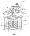
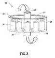
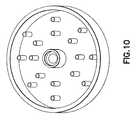
様々な特定の実施形態において、本発明の実施に有用に用いられる種類の気化器を図1に示す。図2は、図1に示す種類の気化器の容器に配置された複数の通気式スルーチューブの平面図である。図3は、複数の円筒形スルーチューブを示した、図1に図示する一般的な種類の気化器容器の側面図である。 In various specific embodiments, a type of vaporizer usefully used in the practice of the present invention is shown in FIG. FIG. 2 is a plan view of a plurality of vented through tubes arranged in a container of a vaporizer of the type shown in FIG. FIG. 3 is a side view of the general type vaporizer vessel illustrated in FIG. 1 showing a plurality of cylindrical through tubes.
気化器送出システム10は、容器12を含み、これは、好適な熱伝導性材料で製造されており、例えば、銀、銀合金、銅、銅合金、アルミニウム、アルミニウム合金、鉛、ニッケルクラッド、ステンレス鋼、グラファイト、炭化ケイ素コートグラファイト、窒化ホウ素、セラミック材料等、かかる種類の材料の2つ以上の組み合わせ、混合物および合金である。 The
容器は、床14と、周囲にある側壁16を含み、これらは併せて、容器の内部容積部分を形成している。容器は、キャリアガスがその内部容積部分を均一に流れることを促進する任意の形状を有することができる。一実施形態において、容器は、ほぼ許容差(例えば、1/1000〜3/1000インチの範囲)の非常に近くまで機械加工された円筒形状を有する。 The container includes a
容器は、蓋18を含み、その上には、キャリアガス入口バルブ20が装着されていて、バルブが開いているときは、キャリアガスを、容器の内部容積部分に選択的に導入するように構成されている。 The container includes a
複数の垂直積層トレイ22が容器の内部容積部分に配置されている。積層トレイは、互いに分離可能で、容器から取り出し可能で、クリーニングおよび差し替えが容易である。内部キャリアガスダウンチューブ23が容器内に配置されており、これは、入口バルブ20に関連付けられた蓋のガス入口に接続(溶接)されていて、キャリアガスを、垂直積層トレイの配列の最下トレイより下の内部容積部分の底部まで運ぶ。図1において、ダウンチューブ23は、トレイの床24を通して延在する各トレイの円筒カラー27を通過している(図3参照)。当然のことながら、ダウンチューブの連結点で、トレイの床24との漏れ止めシールを確保するために、ソース材料が液体の場合は特に、シーリングO−リング38を、連続したトレイ間に配置してもよい。追加の外側O−リングを用いて、各トレイ側壁の上面にあるトレイ間をシールすることもできる。 A plurality of vertically stacked
ソース試薬が固体形態のときは、様々な構造要素を用いて、キャリアガスフローに固体が同伴することを抑制または最小にしてもよい。かかる同伴に対抗する特徴部は、任意の好適な種類でよく、例えば、フリット要素およびフリット以外の粒子抑制特徴部またはデバイスであってよい。フリット以外の粒子抑制特徴部としては、様々な実施形態において、蛇行した流路、上向流固体離脱構造、粒子凝集または収集特徴部として作用する接線ガスフロー側流等が挙げられる。具体例を挙げると、高純度ステンレス鋼フリット、例えば、孔径が1〜100ミクロンのもの、そしてフリット以外の少なくとも1つの粒子抑制特徴部を、好適な場所に加えると、キャリアガス流量を制御することができる。フリットは、例えば、トレイに関連付けられた各スルーチューブ30の「入口」に装着したり、大きなディスクフリットを上部トレイに加えて、容器の蓋の取付けからの圧力によりシールする、あるいは、出口ガス流路に配置することができる。 When the source reagent is in solid form, various structural elements may be used to suppress or minimize entrainment of the solid in the carrier gas flow. The feature to counter such entrainment may be of any suitable type, for example, a frit element and a particle suppression feature or device other than a frit. Particle suppression features other than frits include, in various embodiments, serpentine channels, upward flow solid detachment structures, particle agglomeration or tangential gas flow sidestreams that act as collection features. To give a specific example, adding a high purity stainless steel frit, such as one having a pore size of 1 to 100 microns, and at least one particle suppression feature other than a frit in a suitable location, controls the carrier gas flow rate. Can do. The frit is attached, for example, to the “inlet” of each through
図3に示すように、個別のトレイ22はそれぞれ、床24および側壁26を有していて、ソース材料28の配置および支持のためのトレイキャビティ27が形成されている。トレイは、非反応性熱伝導性材料で製造されるのが好ましく、例えば、銀、銀合金、銅、銅合金、アルミニウム、アルミニウム合金、鉛、ニッケルクラッド、ステンレス鋼、グラファイト、炭化ケイ素コートグラファイト、窒化ホウ素、セラミック材料、前述の2つ以上の組み合わせ、混合物および複合体である。 As shown in FIG. 3, each
個別のトレイはそれぞれ、複数のスルーチューブ30を含み、各スルーチューブは、キャリアガスをスルーチューブを通して搬送するための通路32を含んでいる。スルーチューブは、中をガスが通る任意の形状または構造を有することができる。スルーチューブは、円筒または円錐形であるのが好ましい。スルーチューブは、様々な実施形態において、トレイの床から上方に延在していて、トレイ床の対応開口部と連通する中央通路を画定している。他の実施形態において、スルーチューブは、同様に、トレイの床から上方に延在しているが、トレイの下に下方にも延在していて、中央通路が、トレイの床の上下で、例えば、その中心孔として、スルーチューブに囲まれるようにする。 Each individual tray includes a plurality of through
スルーチューブは、任意の好適なやり方、例えば、溶接、ろう付け、メカニカルファスナ取付具、圧入、かしめ等により、トレイの床に固定することができる。変形例として、スルーチューブは、トレイ床の一部として一体成形することができる。特定の実施形態において、スルーチューブの高さは、トレイ側壁とほぼ同じ高さである。ただし、各スルーチューブの高さが、かかる側壁より高い、または低い他の実施形態も想定される。 The through tube can be secured to the tray floor by any suitable manner, such as welding, brazing, mechanical fastener fitting, press fitting, caulking, and the like. Alternatively, the through tube can be integrally molded as part of the tray floor. In certain embodiments, the height of the through tube is about the same height as the tray sidewall. However, other embodiments are envisioned in which the height of each through tube is higher or lower than such side walls.
各トレイの側壁を十分な高さとし、トレイを積層可能として、気化器の容器の内部容積部分において、垂直に延在する積層アレイが形成されるようにしてもよい。 The side walls of each tray may be sufficiently high so that the trays can be stacked so that a vertically extending stacked array is formed in the internal volume portion of the vaporizer vessel.
他の特定の実施形態において、トレイは、2、3または4方向入口/出口バルブにより利用可能な隔離されたカートリッジを含むことができる。 In other specific embodiments, the tray can include isolated cartridges that are available with 2, 3 or 4 direction inlet / outlet valves.
さらに他の実施形態において、気化器容器の内部壁面に装着または固定できるだけの十分な寸法範囲の側壁をトレイに製造してもよい。 In yet another embodiment, the tray may be manufactured with side walls having a size range sufficient to attach or secure to the inner wall of the vaporizer vessel.
さらなる実施形態において、トレイは側壁なしで製造してもよく、周囲シーリングガスケットまたはその他装着構造または要素と共に、容器の内部壁面の支持を用いて、内部容積部分中に装着してもよい。トレイが垂直に互いに相隔たる関係で、アセンブリとして装着される、さらなる実施形態も想定される。例えば、トレイは、適宜、気化器の組み立ておよび分解中に、容器の内部容積部分に挿入し、取り出される一体型配列として、フレームまたはその他配置構造上に装着することができる。 In further embodiments, the tray may be manufactured without side walls and may be mounted in the interior volume using support of the inner wall of the container, along with a peripheral sealing gasket or other mounting structure or element. Further embodiments are also envisaged in which the trays are mounted as an assembly in a vertically spaced relationship. For example, the trays may be mounted on a frame or other arrangement as an integral arrangement that is inserted and removed from the interior volume of the container, as appropriate, during assembly and disassembly of the vaporizer.
特定の一実施形態において、各トレイは、周囲の側壁を有し、各スルーチューブの高さは、トレイ側壁の高さより低い。これによって、各トレイ内でのガス分散および循環のために、各スルーチューブの上にヘッドスペースが与えられる。 In one particular embodiment, each tray has a peripheral side wall, and the height of each through tube is lower than the height of the tray side wall. This provides headspace above each through tube for gas distribution and circulation within each tray.
あるいは、スルーチューブおよびトレイは、各トレイに流動床を作成するように構成したり、トレイに多孔質開口部を備えるように製造して、固体またはその他ソース試薬材料が、トレイの上面に最初に支持されて、キャリアガスが、ソース試薬を流動化するのに十分な空塔速度で、スルーチューブまたは多孔質開口部を通して流れるようにすることができる。このためには、ソース試薬は、粉末またはその他微粉砕固体形態で、流動化に関連する圧力降下が過剰とならないようにするのが好ましい。かかる構成では、スルーチューブまたは多孔質開口部の寸法は、流動化ガスフローなしで、トレイに支持された固体を保持するよう十分小さい。 Alternatively, the through tubes and trays can be configured to create a fluidized bed in each tray, or can be manufactured with a porous opening in the tray so that the solid or other source reagent material is first on the top of the tray. Supported, the carrier gas can flow through the through tube or porous opening at a superficial velocity sufficient to fluidize the source reagent. To this end, the source reagent is preferably in powder or other finely divided solid form so that the pressure drop associated with fluidization is not excessive. In such a configuration, the dimensions of the through tube or porous opening are small enough to hold the solid supported on the tray without fluidizing gas flow.
より一般的には、スルーチューブは、固体であろうと液体であろうと十分量のソース材料を配置するための漏れ止め領域を与える高さを有していて、スルーチューブの開放通路32を通して、下にある容器へ固体または液体が漏れることなく、必要な気化材料を与えるのが望ましい。一実施形態において、各スルーチューブは、トレイの下部から、例えば、約0.5mm〜約5mmの範囲、より好ましくは、約1.5mm〜約3.0mmの範囲の高さまで垂直に上方に延在している。 More generally, the through tube has a height that provides a leak-proof region for placing a sufficient amount of source material, whether solid or liquid, through the
図1に示すように、各トレイにおけるスルーチューブの位置を、近接するトレイのスルーチューブの位置から僅かにずらすと、得られたガス混合物が、スルーチューブを通して次の近接するトレイ領域へ搬送される前に、キャリアガスを付勢して、キャリアガスを、気化したソース材料と接触させるように、トレイ内を循環する。かかる構成により、キャリアガスを、ソース試薬材料と様々なレベルで接触させると、極めて効率的なやり方で、キャリアガスが飽和される。 As shown in FIG. 1, when the position of the through tube in each tray is slightly shifted from the position of the through tube of the adjacent tray, the resulting gas mixture is transported through the through tube to the next adjacent tray area. Before, the carrier gas is energized and circulated through the tray so that the carrier gas is in contact with the vaporized source material. With such an arrangement, contacting the carrier gas with the source reagent material at various levels saturates the carrier gas in a highly efficient manner.
気化器送出システム10のサイズは、CVD装置やイオン注入システム等の下流の流体を利用する設備に供給される蒸気の量に応じて大きく異なる。一実施形態において、気化器は、約3〜6インチの範囲、例えば、約3.75インチの内径の円筒構成を有する。気化器容器の内部容積部分にあるトレイの数は、気化器のサイズにより決まる。様々な実施形態において、3〜5つのトレイが、気化器容器内にある。 The size of the
多数のトレイを含む気化器は、加熱し、気化する具体的なソース材料にとって適切な所望の温度、下流の流体を利用する設備まで、気化器から送出されるキャリアガス混合物中のソース試薬の所望の濃度、およびソース試薬気化操作に用いられる特定の組み合わせの操作条件に保つことができる。 Vaporizers containing multiple trays are desired for the source reagent in the carrier gas mixture delivered from the vaporizer, up to the desired temperature appropriate for the particular source material to be heated and vaporized, up to facilities utilizing downstream fluids. And the specific combination of operating conditions used for the source reagent vaporization operation.
気化器容器の加熱は、任意の好適なやり方で実施することができる。一実施形態においては、リボンヒータを気化器周囲に巻きつける。他の実施形態においては、気化器の外面の少なくとも主要部分をカバーする形状を有するブロックヒータを用いて、気化器容器を加熱する。さらに他の実施形態においては、高温で熱伝達流体を、気化器容器の外面と接触させて、その加熱を行ってもよい。さらなる実施形態には、気化器容器に衝突する赤外またはその他放射エネルギーによる加熱が含まれる。 Heating the vaporizer vessel can be performed in any suitable manner. In one embodiment, a ribbon heater is wrapped around the vaporizer. In another embodiment, the vaporizer vessel is heated using a block heater having a shape that covers at least a major portion of the outer surface of the vaporizer. In yet another embodiment, the heat transfer fluid may be brought into contact with the outer surface of the vaporizer vessel and heated at a high temperature. Further embodiments include heating by infrared or other radiant energy impinging on the vaporizer vessel.
本発明は、さらなる実施形態において、容器においてホットガスを循環させることにより、ソース試薬を加熱して、ソース試薬の対流加熱を行うことが想定される。 In a further embodiment, the present invention envisions performing convective heating of the source reagent by heating the source reagent by circulating hot gas in the vessel.
気化器容器の加熱方法は、気化器がそれによって所望の温度レベルとなり、かかる温度レベルが、正確かつ信頼性のあるやり方で維持される限りは、特に限定されない。 The method of heating the vaporizer vessel is not particularly limited as long as the vaporizer is thereby at the desired temperature level and such temperature level is maintained in an accurate and reliable manner.
熱的に均一なやり方で、気化器容器を加熱して、容器の内部容積部分における温度変位が最少となるようにするのが望ましい。トレイが、壁と直接熱的に接触する特定の実施形態において、壁からの熱伝導を介したかかるトレイの加熱は、ソース試薬をトレイで気化するのに簡便かつ効率的なやり方を提供するものである。 It is desirable to heat the vaporizer vessel in a thermally uniform manner so that the temperature displacement in the inner volume of the vessel is minimized. In certain embodiments where the tray is in direct thermal contact with the wall, heating of such tray via heat conduction from the wall provides a convenient and efficient way to vaporize the source reagent in the tray. It is.
ある用途においては、気化器容器の内部容積部分で、追加の表面積構造を利用して、気化のためのソース試薬材料の加熱の範囲および速度を向上させるのが望ましい。 In some applications, it is desirable to utilize an additional surface area structure in the interior volume of the vaporizer vessel to improve the range and rate of heating of the source reagent material for vaporization.
ソース材料の高効率気化を達成するための他の手段として、気化器容器の内部容積部分に導入する前にキャリアガスを加熱して、ソース試薬の加熱およびその気化を補助してもよい。例えば、キャリアガスを入口バルブ20へ供給するフローラインをヒートトレースする、またはその他加熱して、キャリアガスを気化器容器へ所望の温度レベルで送出してもよい。 As another means to achieve high efficiency vaporization of the source material, the carrier gas may be heated prior to introduction into the internal volume of the vaporizer vessel to assist in heating the source reagent and its vaporization. For example, the flow line supplying the carrier gas to the
昇華可能な固体ソース試薬からの蒸気送出のための特定の構成において、本発明の気化器送出システムは、加熱表面積を増大する複数の加熱したスルーチューブを含む一連の加熱トレイを利用する。これによって、固体ソース材料の昇華が、熱の増大した分布の結果、高効率なやり方で達成可能となる。 In a particular configuration for vapor delivery from a sublimable solid source reagent, the vaporizer delivery system of the present invention utilizes a series of heating trays that include a plurality of heated through tubes that increase the heating surface area. This allows sublimation of the solid source material to be achieved in a highly efficient manner as a result of the increased distribution of heat.
ある用途においては、処理中、より一貫した温度を維持するために、気化器容器の熱質量が大きいのが望ましい。大きな熱質量を用いることは、固体ソース材料を、固体状態から蒸気状態まで昇華する用途においては特に重要である。ある温度で、固体の蒸気圧は、固体/ガス界面での材料の分圧である。すなわち、ある時間における、固体表面に凝縮している分子の数が、表面から昇華している分子の数と同じということである。気相状態にある分子が、キャリアガスにより、固体/ガス界面から除去されると、平衡が壊れる。十分な熱が、固体の表面に供給されて、固体の昇華の潜熱が補われる場合には、明らかに、昇華は、高速で起こって、平衡が回復する。複数の加熱したスルーチューブを、加熱した気化器容器壁に関連付けられた加熱したトレイに提供することにより、全体の熱伝導性容器は、昇華速度を増大する機能を果たして、飽和したキャリアガスの流量を増大し、トレイのスルーチューブまたはその他孔またはチャネルを閉塞させ得る気化したソース材料の沈殿を減少する。 In some applications, it is desirable for the vaporizer vessel to have a high thermal mass in order to maintain a more consistent temperature during processing. The use of a large thermal mass is particularly important in applications where the solid source material is sublimated from the solid state to the vapor state. At some temperature, the vapor pressure of a solid is the partial pressure of the material at the solid / gas interface. That is, the number of molecules condensed on the solid surface at a certain time is the same as the number of molecules sublimated from the surface. When molecules in the gas phase are removed from the solid / gas interface by the carrier gas, the equilibrium is broken. Obviously, if sufficient heat is supplied to the surface of the solid to compensate for the latent heat of sublimation of the solid, sublimation will occur at high speed and equilibrium will be restored. By providing multiple heated through tubes to the heated tray associated with the heated vaporizer vessel wall, the overall thermally conductive vessel functions to increase the sublimation rate, and the saturated carrier gas flow rate To reduce precipitation of vaporized source material that can occlude tray through tubes or other holes or channels.
ある用途に用いられる気化器の特定の温度は、下流の流体を利用する装置、例えば、CVD装置またはイオン注入システムの操作条件、提供されるソース材料の蒸気圧および量に応じて異なる。昇華可能な固体ソース試薬を用いる様々な特定の実施形態において、約40℃〜約300℃の範囲の気化器温度を用いることができる。金属ハロゲン化物固体ソース試薬を含む本発明の実施では、特定の実施形態において、例えば、200℃〜300℃の範囲の温度を利用することができる。 The specific temperature of the vaporizer used for a given application will vary depending on the operating conditions of the device utilizing the downstream fluid, such as a CVD device or ion implantation system, the vapor pressure and amount of source material provided. In various specific embodiments using sublimable solid source reagents, vaporizer temperatures in the range of about 40 ° C. to about 300 ° C. can be used. Implementations of the invention involving a metal halide solid source reagent may utilize temperatures in the range of, for example, 200 ° C. to 300 ° C. in certain embodiments.
本発明の気化器送出システムは、特定の実施形態において、キャリアガスを、気化器容器に供給するライン、ソース試薬蒸気を、気化器容器から放出するライン、流れ制御バルブ、質量流コントローラ、レギュレータ、制限流オリフィス要素、熱電対、圧力変換器、モニタリングおよびコントロールデバイス、熱エネルギーを気化器容器およびその中身に与えるヒータ、キャリアガス供給ラインおよびソース試薬蒸気放出ラインの温度を維持するヒータ等のフロー回路コンポーネント等をさらに含む。 The vaporizer delivery system of the present invention comprises, in certain embodiments, a line for supplying carrier gas to the vaporizer vessel, a line for releasing source reagent vapor from the vaporizer vessel, a flow control valve, a mass flow controller, a regulator, Flow circuits such as restricted flow orifice elements, thermocouples, pressure transducers, monitoring and control devices, heaters that provide thermal energy to the vaporizer vessel and its contents, heaters that maintain the temperature of the carrier gas supply line and source reagent vapor discharge line It further includes components and the like.
本発明のある実施形態において、ソース試薬蒸気放出ラインの加熱を行って、かかる放出ラインにおける凝縮を防ぐために、かかるラインの温度を、気化温度より5〜10℃高く維持する。 In certain embodiments of the invention, the temperature of such a line is maintained 5-10 ° C. above the vaporization temperature in order to heat the source reagent vapor discharge line to prevent condensation in such discharge line.
本発明の気化器システムの使用において、カバーを容器に固定する前に、トレイに含まれるまたは気化器容器の内部容積部分にその他配置された気化器容器に、ソース試薬材料を導入することができる(図1参照。カバー18は、ボルトメカニカルファスナにより、容器に固定されている)。ソース試薬材料は、固体形態、液体形態、半固体形態、あるいは好適な溶剤媒体に溶解または分散されたソース試薬材料を含有する溶液をはじめとする任意の好適な形態であってよい。 In use of the vaporizer system of the present invention, the source reagent material can be introduced into a vaporizer container contained in the tray or otherwise disposed in the internal volume of the vaporizer container prior to securing the cover to the container. (See FIG. 1. The
一実施形態において、ソース試薬材料は、トレイの表面およびトレイキャビティ内のスルーチューブにコートされた堆積物の形態で、好適な厚さのフィルムまたはコーティングとして提供される。かかるフィルムまたはコーティングは、任意の様々な好適な方法により形成してよく、ソース試薬を加熱することにより溶融し、溶融ソース試薬材料をトレイおよびスルーチューブの表面に適用し、適用した材料を冷却する方法が挙げられる。 In one embodiment, the source reagent material is provided as a film or coating of a suitable thickness in the form of a deposit coated on the surface of the tray and through tubes within the tray cavity. Such a film or coating may be formed by any of a variety of suitable methods, where the source reagent is melted by heating, the molten source reagent material is applied to the surface of the tray and through tube, and the applied material is cooled. A method is mentioned.
ソース試薬が、金属錯体を含む他の実施形態において、金属錯体は、溶剤に溶解し、得られた溶液は、トレイおよびスルーチューブの表面に適用した後、溶剤を適用された材料から減圧下で除去する。 In other embodiments where the source reagent comprises a metal complex, the metal complex is dissolved in a solvent, and the resulting solution is applied to the surface of the tray and through tube, and then the solvent is applied under reduced pressure from the applied material. Remove.
ある実施形態において、異なるソース試薬蒸気種を、気化器容器から、下流の流体を利用する設備まで同時に供給するのが望ましい。かかる用途において、異なるソース試薬材料は、気化器容器内部容積部分の異なるトレイおよび/または異なるカートリッジに提供することができる。かかる構成により、キャリアガスにより下流設備へ運ばれる多成分蒸気を生成することができる。 In certain embodiments, it may be desirable to supply different source reagent vapor species simultaneously from the vaporizer vessel to the facility utilizing the downstream fluid. In such applications, different source reagent materials can be provided in different trays and / or different cartridges of the vaporizer container internal volume. With this configuration, it is possible to generate multi-component vapor that is carried to the downstream facility by the carrier gas.
気化器は、このように、気化器容器の内部容積部分中の中央ダウンチューブに装着された複数の垂直積層トレイを含むことができる。所定量のソース試薬、例えば、計量した量の微粒子固体を、トレイに充填することにより、容器の内部容積部分に、ソース試薬材料を充填することができる。気化器容器にソース試薬をこのように充填した後、容器の上部蓋18(図1および2参照)を、容器の上部に配置し、例えば、ポリテトラフルオロエチレンまたはエラストマーで製造されたo−リング要素により、または金属シール要素および/またはファスナ、例えば、ボルトファスナによりシールする。 The vaporizer can thus include a plurality of vertically stacked trays attached to a central down tube in the interior volume of the vaporizer vessel. By filling a tray with a predetermined amount of source reagent, eg, a metered amount of particulate solid, the interior volume of the container can be filled with source reagent material. After such filling of the vaporizer container with the source reagent, the container top lid 18 (see FIGS. 1 and 2) is placed on top of the container and is, for example, an o-ring made of polytetrafluoroethylene or elastomer Seal by element or by metal seal element and / or fastener, eg bolt fastener.
気化器の組み立て、キャリアガスの容器への送出のための気化器容器のプロセスラインとの結合、およびソース試薬蒸気を含有するキャリアガス混合物の容器からの放出の後、気化器ヒータを作動させて、気化器容器を加熱する。加熱を行って、気化器および接触トレイ内の内部温度を、ソース材料が気化するのに十分な温度まで上げる。 After assembly of the vaporizer, coupling to the vaporizer vessel process line for delivery of the carrier gas to the vessel, and release of the carrier gas mixture containing the source reagent vapor from the vessel, the vaporizer heater is activated. Heat the vaporizer vessel. Heat is applied to raise the internal temperature in the vaporizer and contact tray to a temperature sufficient for the source material to vaporize.
昇華可能な固体の場合には、昇華速度は、最初、または最下のトレイで最大となる。そのトレイに入るキャリアガスは、その上にあるトレイに入る部分的または完全に飽和したキャリアガスに対して純粋なためである。このように、より多くのソース試薬材料を、下部トレイに充填し、かつ/または容器の高さ寸法を増やして、所望量のソース試薬蒸気が、生成されて、下流の流体を利用する設備へ流れるようにする必要がある。 In the case of a sublimable solid, the sublimation rate is maximum at the first or bottom tray. This is because the carrier gas entering the tray is pure relative to the partially or fully saturated carrier gas entering the tray above it. In this way, more source reagent material is filled into the lower tray and / or the container height dimension is increased so that the desired amount of source reagent vapor is generated to the facility utilizing the downstream fluid. It needs to flow.
本発明の気化器システムは、様々なソース試薬材料から蒸気を生成するのに有利に用いられ、デカボラン、四塩化ハフニウム等といった昇華可能な固体の気化に特に有用である。本発明は、固体ソース材料、例えば、約20℃〜約300℃の範囲の昇華温度、昇華温度で、約10−2トル〜約103トルの範囲の蒸気圧を有する固体材料の気化のための様々な用途に有用である。The vaporizer system of the present invention is advantageously used to generate vapor from a variety of source reagent materials and is particularly useful for vaporizing sublimable solids such as decaborane, hafnium tetrachloride, and the like. The present invention is for vaporizing a solid source material, such as a solid material having a sublimation temperature in the range of about 20 ° C. to about 300 ° C., a sublimation temperature, and a vapor pressure in the range of about 10−2 Torr to about 103 Torr. It is useful for various applications.
これらに限られるものではないが、制御された温度操作のために構築および構成された、ストリップヒータ、放射ヒータ、加熱エンクロージャ、循環流体ヒータ、抵抗加熱システム、誘導加熱システム等をはじめとする任意の加熱制御システムにより、気化器内で温度は制御される。さらに、気化器内の温度は、熱電対、サーミスタまたは熱伝導性容器および/またはその中のトレイの表面と接触するように構成された任意のその他好適な温度センシングジャンクションまたはデバイスによりセンシングすることができる。かかる温度センシングデバイスは、中央処理ユニット、例えば、汎用プログラム可能コンピュータ、プログラム可能論理ユニット、マイクロコントローラ等と操作可能に結合することができ、これらは、温度センシングデバイスから温度センシング信号を受信し、ヒータおよび/または気化器システムの制御可能な要素に応答して調節されて、特定の用途に望ましいソース試薬蒸気を生成できるように構成されている。 Any, but not limited to, strip heaters, radiant heaters, heating enclosures, circulating fluid heaters, resistance heating systems, induction heating systems, etc., constructed and configured for controlled temperature operation The temperature is controlled in the vaporizer by a heating control system. Further, the temperature in the vaporizer may be sensed by a thermocouple, thermistor or thermally conductive container and / or any other suitable temperature sensing junction or device configured to contact the surface of the tray therein. it can. Such a temperature sensing device can be operably coupled to a central processing unit, eg, a general purpose programmable computer, programmable logic unit, microcontroller, etc., which receives a temperature sensing signal from the temperature sensing device, and a heater And / or can be adjusted in response to controllable elements of the vaporizer system to be configured to produce the desired source reagent vapor for a particular application.
気化器においてソース材料が激減しているか判断するには、トレイの下面の反射面に通信可能に接続された光学センサ等のレベルセンサモニタリングシステムを用いて、気化器容器の内部容積部分にある上部トレイおよび/または下部トレイの固体または液体の量を求めて、トレイがほぼ空または空のときは信号を変化させることができる。 To determine if the source material is drastically reduced in the vaporizer, a level sensor monitoring system such as an optical sensor communicatively connected to the reflective surface on the underside of the tray can be used. The amount of solid or liquid in the tray and / or lower tray can be determined to change the signal when the tray is nearly empty or empty.
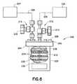
図4は、本発明の様々な実施形態で有用に用いられる蒸気送出システム66構成の簡略概略図である。 FIG. 4 is a simplified schematic diagram of a
このシステムは、気化器10を含む。キャリアガス源64は、気化器10に接続されていて、キャリアガスを提供する。ソース材料を導入する変形モードにおいて、液体ソース材料は、液体ソース容器67から気化器に導入する、あるいは、気化器10は、顆粒または微粒子形態の固体ソース試薬で予め充填することができる。 The system includes a
キャリアガスの流量は、キャリアガス送出ライン、および気化したソース材料を処理チャンバ70に搬送するラインに配置された流量計68によりモニタリングおよび制御される。ガス送出ラインは、特定の一実施形態において、低摩擦係数を有する材料、例えば、ポリマーで製造されていて、高流速が達成できる。気化器10は、熱伝導性材料で製造されていると有利で、気化器容器およびその中身を加熱するために、気化器ユニット10に通信可能に接続された少なくとも1つのヒータ72により生成された熱エネルギーの伝達を可能とする。 The flow rate of the carrier gas is monitored and controlled by a
気化したソース試薬、および気化したソース試薬と混合されて、蒸着チャンバまたはその他下流のプロセスユニットに流れるキャリアガスのモニタリングおよび制御のためには、本発明の一実施形態において、2004年11月23日発行の米国特許第6,821,795号明細書、2006年3月14日発行の米国特許第7,011,614号明細書または2003年9月9日発行の米国特許第6,617,175号明細書に記載された種類の熱電対列赤外検出モニタリングシステムを、2005年6月21日発行の米国特許第6,909,973号明細書、2006年6月6日発行の米国特許第7,058,519号明細書または2006年6月20日発行の米国特許第7,063,097号明細書に記載された種類のブレンダーシステムと共に用いることができる。かかる熱電対列赤外検出モニタリングシステムおよびブレンダーシステムは、例えば、気化器および試薬ソースを含むプロセスシステムのフロー回路のバイパスラインに配置することができる。 For monitoring and controlling the vaporized source reagent and carrier gas mixed with the vaporized source reagent and flowing to the deposition chamber or other downstream process unit, in one embodiment of the present invention, November 23, 2004 U.S. Pat. No. 6,821,795 issued, U.S. Pat. No. 7,011,614 issued on Mar. 14, 2006, or U.S. Pat. No. 6,617,175 issued on Sep. 9, 2003 No. 6,909,973 issued Jun. 21, 2005 and U.S. Pat. No. 6,066,2006 issued to June 21, 2006. A blender system of the type described in US Pat. No. 7,058,519 or US Pat. No. 7,063,097 issued June 20, 2006 It can be used with. Such a thermopile infrared detection monitoring system and blender system can be located, for example, in the bypass line of the flow circuit of a process system including a vaporizer and a reagent source.
完全な気化に必要な出力量は、ソース材料およびキャリアガスの化学的性質と混合物の流量の関数である。特定の実施形態において、気化器に移る熱出力は、約100W〜約3000Wの範囲で、ソース試薬気化のための高効率等温温度を与える。 The amount of power required for complete vaporization is a function of the source material and carrier gas chemistry and the flow rate of the mixture. In certain embodiments, the heat output transferred to the vaporizer provides a highly efficient isothermal temperature for source reagent vaporization in the range of about 100 W to about 3000 W.
図4に示す種類の気化器システムの操作において、固体ソース試薬材料を用いるとき、ソース試薬材料を、ドライボックスまたはグローブボックスのトレイに充填すると、気化容器が開放されている間、前駆体の酸素および湿度との反応を排除することができる。次に、ドライボックスまたはグローブボックスの容器に、ソース試薬含有トレイを充填し、蓋をして、適所に固定し、密閉した気化容器とする。次に、容器を、供給および放出ラインと結合して、プロセスシステムにおいて、キャリアガスを放出し、蒸気含有キャリアガス混合物を放出する。 In the operation of a vaporizer system of the type shown in FIG. 4, when using solid source reagent material, filling the source reagent material into the tray of a dry box or glove box causes the precursor oxygen to remain open while the vaporization vessel is open. And reaction with humidity can be eliminated. Next, the container of the dry box or glove box is filled with the source reagent-containing tray, covered, fixed in place, and a sealed vaporization container is obtained. The container is then coupled with supply and discharge lines to release carrier gas and vapor-containing carrier gas mixture in the process system.
次に、ガス源64からのキャリアガスが、1標準立方センチメートル毎分(sccm)〜約500sccmの範囲のガス流量で、キャリアガス入口20で気化器に導入される。キャリアガスは、気化器へ適切な圧力で搬送され、もって気化器容器に導入されて容器の下部から流れる定常流のキャリアガスが提供されるが、そこでキャリアガスは、内部容積部分を通して外方かつ上方に、連続したトレイおよびそのスルーチューブを通して導入される。 The carrier gas from the
キャリアガスが、異なるレベルの垂直積層トレイを通して上方に流れるにつれて、キャリアガスは、気化したソース試薬材料で飽和される。次に、ソース試薬蒸気を含有する得られたキャリアガス混合物は、ガス出口バルブ40で、気化器から、プロセスチャンバ70へ流れる。プロセスチャンバ70は、分散したソース試薬蒸気を含有するキャリアガス混合物が、処理または利用される任意の好適な種類とすることができる。特定の一実施形態において、プロセスチャンバ70は、原子層蒸着チャンバまたはイオン注入チャンバを含む。 As the carrier gas flows upward through different levels of vertically stacked trays, the carrier gas is saturated with vaporized source reagent material. The resulting carrier gas mixture containing the source reagent vapor then flows from the vaporizer to the
本発明の実施に有用に用いられる好ましい気化器は、図1〜3に関して記載した種類であり、ATMI, Inc., Danbury, Connecticut USAよりProE-Vap(登録商標)という商品名で市販されている。ProE-Vap気化器は、ソース試薬を含有する積層トレイを利用している。かかる気化器においては、キャリアガスは、上端から導入され、後の分布のために、下方に延在する供給管から、容器の下部へ流れて、容器の内部容積部分にある各トレイを上方に流れる。このようにして、容器は、加熱されると、容器内部容積部分内のトレイを伝導的に加熱して、ソース試薬に由来する蒸気をトレイに生成する。生成された蒸気は、キャリアガスに同伴される。次に、ソース試薬蒸気を含む得られたキャリアガス混合物は、その上端で、容器の出口ポートを通して、気化器から放出される。出口ポートから、ソース試薬蒸気を含有するキャリアガス混合物は、気化器の放出バルブを通る。放出バルブは、化学蒸着チャンバ、ALDチャンバまたはイオン注入器等の下流の処理ユニットに関連付けられたフロー回路に結合して、ソース試薬蒸気を含有するキャリアガス混合物を、気化器容器からかかる下流の流体処理設備へ流す。 A preferred vaporizer usefully used in the practice of the present invention is of the type described with respect to FIGS. 1-3 and is commercially available from ATMI, Inc., Danbury, Connecticut USA under the trade name ProE-Vap®. . The ProE-Vap vaporizer utilizes a stacked tray containing the source reagent. In such a vaporizer, the carrier gas is introduced from the upper end and, for later distribution, flows from the supply pipe extending downward to the lower part of the container, and upwards each tray in the internal volume part of the container. Flowing. In this way, when the container is heated, it conductively heats the tray in the interior volume of the container, generating vapor from the source reagent in the tray. The generated steam is accompanied by a carrier gas. The resulting carrier gas mixture containing the source reagent vapor is then discharged from the vaporizer at its upper end through the outlet port of the vessel. From the outlet port, the carrier gas mixture containing the source reagent vapor passes through the vaporizer discharge valve. The discharge valve is coupled to a flow circuit associated with a downstream processing unit, such as a chemical vapor deposition chamber, ALD chamber, or ion implanter, to transfer the carrier gas mixture containing the source reagent vapor from the vaporizer vessel to the downstream fluid. Flow to treatment facility.
他の気化器を本発明の実施に用いることができ、例えば、その開示内容がここに参考文献として援用される2005年2月23日公開の欧州特許出願第1508631号明細書「前駆体材料の送出のための方法および装置(Method and Apparatus for the Delivery of Precursor Materials)」に記載された気化器が挙げられる。この公開特許出願には、少なくとも1つの突出部が、容器の容積の下部へと延在していて、前駆体と接触し、少なくとも1つの突出部が、容器の蓋、側壁および/または基部から延在している気化器容器が記載されている。容器は、蓋に入口および出口ポートを有していて、フロー回路と連通していて、キャリアガスを、容器の内部容積部分に流して、加熱した前駆体の蒸気と接触するように構成されている。従って、突出部は、面積の増大した熱伝達要素として作用して、前駆体の気化および容器内のキャリアガスの流れ分布が促進される。 Other vaporizers can be used in the practice of the present invention, for example, European Patent Application No. 1508631, published February 23, 2005, the disclosure of which is incorporated herein by reference. And vaporizers described in “Method and Apparatus for the Delivery of Precursor Materials”. In this published patent application, at least one protrusion extends into the lower part of the volume of the container and contacts the precursor, and at least one protrusion extends from the lid, side wall and / or base of the container. An extended vaporizer vessel is described. The vessel has inlet and outlet ports in the lid, is in communication with the flow circuit, and is configured to flow a carrier gas through the inner volume of the vessel to contact the heated precursor vapor. Yes. Thus, the protrusion acts as a heat transfer element with an increased area, which promotes precursor vaporization and carrier gas flow distribution within the vessel.
本発明の広範な実施に用いてよい他の実例となる気化器は、同じくその開示内容がここに参考文献として援用される2006年2月2日公開の米国特許出願公開第2006/0024439号明細書「反応物質の昇華を制御するためのシステム(System for Controlling the Sublimation of Reactants)」に記載されている。かかる参考文献に記載されている気化器は、熱伝導性容器を含み、前駆体を、前駆体と熱伝導性材料の混合物から気化する。熱伝導性材料は、ロッド、粉末、スクリーン、篩、コイル、プレート等の形態で存在していてもよい。 Another illustrative vaporizer that may be used in the broad implementation of the present invention is also disclosed in US Patent Application Publication No. 2006/0024439, published February 2, 2006, the disclosure of which is also incorporated herein by reference. Document “System for Controlling the Sublimation of Reactants”. The vaporizer described in such references includes a thermally conductive container and vaporizes the precursor from a mixture of the precursor and the thermally conductive material. The thermally conductive material may be present in the form of a rod, powder, screen, sieve, coil, plate or the like.
本発明の広範な実施に用いてよい他の気化器は、同じくその開示内容がここに参考文献として援用される2005年7月26日発行の米国特許第6,921,062号明細書「気化器送出アンプル(Vaporizer Delivery Ampoule)」に記載されている。この特許に記載された蒸気は、トレイ等、垂直積層容器を含んでおり、かかる容器の床を通る蒸気流管を有していて、内部容積部分を通して、容器の出口ポートへ試薬蒸気が流れるようになっている。容器は、キャリアガス管を備えていて、キャリアガスを、容器の内部容積部分へ導入し、蒸気流管チャネルによって、キャリアガスが、積層容器中の固体、例えば、垂直積層各トレイの面にあるソース試薬固体と接触できる。 Other vaporizers that may be used in the broad practice of the present invention are described in US Pat. No. 6,921,062, issued July 26, 2005, the vaporization of which is also incorporated herein by reference. Vaporizer Delivery Ampoule ”. The vapor described in this patent includes a vertically stacked container such as a tray and has a vapor flow tube through the floor of such container so that reagent vapor flows through the interior volume to the outlet port of the container. It has become. The container is equipped with a carrier gas tube, which introduces the carrier gas into the interior volume of the container, and by means of a vapor flow tube channel, the carrier gas is on the surface of each tray in a stacked container, e.g. vertically stacked Can contact source reagent solids.
本発明は、様々な特定の態様において、固体または液体ソース試薬からソース試薬蒸気を生成し、送出するための気化器システムに関する。ソース試薬は、かかるソース試薬に由来する蒸気中に粒子を生成または存在させやすい。本発明は、対応蒸気中に粒子を生成および存在させやすい固体ソース試薬に対して、特に有用な用途がある。 The present invention, in various specific aspects, relates to a vaporizer system for generating and delivering source reagent vapor from a solid or liquid source reagent. Source reagents tend to generate or exist particles in the vapor derived from such source reagents. The present invention has particularly useful applications for solid source reagents that tend to produce and exist particles in the corresponding vapor.
本発明の気化器システムが有用に用いられる固体前駆体は、固体相金属ハロゲン化物、有機金属固体等をはじめとする任意の好適な種類とすることができる。本発明の実施に用いられるソース試薬としては、これらに限られるものではないが、ジメチルヒドラジン、トリメチルアルミニウム(TMA)、四塩化ハフニウム(HfCl4)、四塩化ジルコニウム(ZrCl4)、三塩化インジウム、三塩化アルミニウム、ヨウ化チタン、タングステンカルボニル、Ba(DPM)2、ビスジピバロイルメタナトストロンチウム(Sr(DPM)2)、TiO(DPM)2、テトラジピバロイルメタナトジルコニウム(Zr(DPM)4)、デカボラン、ホウ素、マグネシウム、ガリウム、インジウム、アンチモン、銅、リン、ヒ素、リチウム、テトラフルオロホウ酸ナトリウム、アルキル−アミジナートリガンドを組み込んだ前駆体、有機金属前駆体、ジルコニウム第3級ブトキシド(Zr(t−OBu)4)、テトラキスジエチルアミノジルコニウム(Zr(Net2)4)、テトラキスジエチルアミノハフニウム(Hf(NEt2)4)、テトラキス(ジメチルアミノ)チタン(TDMAT)、tertブチルイミノトリス(ジエチルアミノ)タンタル(TBTDET)、ペンタキス(デメチルアミノ)タンタル(PDMAT)、ペンタキス(エチルメチルアミノ)タンタル(PEMAT)、テトラキスジメチルアミノジルコニウム(Zr(NMe2)4)、ハフニウム第3級ブトキシド(Hf(tOBu)4)、二フッ化キセノン(XeF2)、四フッ化キセノン(XeF4)、六フッ化キセノン(XeF6)、前述したものの2つ以上の相溶性のある組み合わせおよび混合物が挙げられる。The solid precursor in which the vaporizer system of the present invention is useful can be of any suitable type including solid phase metal halides, organometallic solids and the like. Source reagents used in the practice of the present invention include, but are not limited to, dimethylhydrazine, trimethylaluminum (TMA), hafnium tetrachloride (HfCl4 ), zirconium tetrachloride (ZrCl4 ), indium trichloride, Aluminum trichloride, titanium iodide, tungsten carbonyl, Ba (DPM)2 , bisdipivaloylmethanatostrontium (Sr (DPM)2 ), TiO (DPM)2 , tetradipivaloylmethanatozirconium (Zr (DPM)4 ), Decaborane, boron, magnesium, gallium, indium, antimony, copper, phosphorus, arsenic, lithium, sodium tetrafluoroborate, precursor incorporating alkyl-amidinate ligand, organometallic precursor, zirconium tertiary Butoxide (Zr (-OBu) 4), tetrakis (diethylamino) zirconium (Zr(Net2) 4), tetrakis (diethylamino) hafnium (Hf(NEt2) 4), tetrakis (dimethylamino) titanium (TDMAT), tert-butyl imino-tris (diethylamino) tantalum (TBTDET ), Pentakis (demethylamino) tantalum (PDMAT), pentakis (ethylmethylamino) tantalum (PEMAT), tetrakisdimethylaminozirconium (Zr (NMe2 )4 ), hafnium tertiary butoxide (Hf (tOBu)4 ), two fluorine Xenon chloride (XeF2 ), xenon tetrafluoride (XeF4 ), xenon hexafluoride (XeF6 ), two or more compatible combinations and mixtures of the foregoing.
前述の材料から選択される実例としては、塩化ハフニウムが、ハフニウムおよびハフニウム含有フィルムを、半導体製造操作において蒸着するのに用いられるソース試薬である。塩化ハフニウムは、塩化ハフニウム固体から生成された蒸気中に微粒子を極めて生成および存在させやすいことがわかっている固体ソース試薬材料である。 Illustratively selected from the aforementioned materials, hafnium chloride is a source reagent used to deposit hafnium and hafnium-containing films in semiconductor manufacturing operations. Hafnium chloride is a solid source reagent material that has been found to be extremely susceptible to the generation and presence of particulates in vapors generated from hafnium chloride solids.
本発明は、気化するとソース試薬蒸気を生じさせる粉末固体の形態のソース試薬材料をはじめとする、粒子を生成しやすいソース試薬材料に関連する特定の問題を解決する様々なアプローチ、装置構成および技術を意図するものである。 The present invention provides a variety of approaches, apparatus configurations, and techniques for solving specific problems associated with source reagent materials that are prone to particle generation, including source reagent materials in the form of powdered solids that when vaporized generate source reagent vapors. Is intended.
これらのアプローチ、構成および技術を、塩化ハフニウム粉末等の粉末固体ソース試薬を具体的に参照して後述するが、その適用性は、多くの場合、様々な液体ソース試薬材料まで拡大され、その使用も含まれるものとする。 These approaches, configurations and techniques are described below with specific reference to powdered solid source reagents such as hafnium chloride powder, but their applicability is often extended to various liquid source reagent materials and their use. Is also included.
粉末固体ソース試薬の使用への適用について広く考えると、本発明のアプローチ、構成および技術には、これらに限られるものではないが、以下のことが含まれる。
(i)前駆体固体材料の所定の粒径範囲および分布を得るための使用の前の粉末ソース試薬のシフティング。
(ii)ソース試薬が気化するときに、粒子生成の存在および程度を最小にするのに最も有利な粒径、組成および形態の選択。
(iii)気化器に結合されたフロー回路の主要流路のバイパス。バイパス流路は、粒子をソース試薬蒸気から除去するための、トラップまたはフィルタを含んでいる。
(iv)キャリアガスとの接触、例えば、ソース試薬固体粒子の溶融または合体前の、熱による固体ソース試薬の粒子の凝集。微粉が、他の粒子との圧密により除去され、固体ソース試薬から生成された蒸気を通らない。
(v)気化器容器中のトレイまたは壁または支持表面への固体ソース試薬の昇華。
(vi)気化器容器の内部容積部分に導入するための、固体ソース試薬のビーズまたはフリット要素上での昇華。
(vii)気化器容器の内部容積部分と同じ導入点での、流入キャリアガスを分散するための拡散器またはフロースプレッダの使用。
(viii)多孔質固体ソース試薬本体の使用。例えば、ポリマーまたはその他一時的な媒体を、固体ソース試薬材料の粉末と混合した後、ポリマー媒体またはその他一時的な媒体を除去して、多孔質固体ソース試薬本体を得ることにより形成可能である。
(ix)ソース試薬蒸気またはこれを含有するキャリアガス混合物からのソース試薬材料粒子の静電的捕捉。
(x)気化器の入口バルブの開口部に入るキャリアガスフローの急激な流れ込みを抑制する、または排除するための、例えば、補助の流れ制御バルブの使用による気化器の初期スタートアップでのキャリアガスの流れの制御。
(xi)気化器蒸気および下流ツールまたはその他流体を利用する設備における圧力の平衡により、例えば、初期の後方の流れを利用して、気化器の入口バルブの開口部に入るキャリアガスフローの急激な流れ込みを抑制する、または排除し、気化器および関連付けられたフロー回路から下流の流体を利用する設備までの気化器流路全体のガスを、実質的に同じ圧力レベルとする。
(xii)ゲートオーバーフローバルブを利用して、高フロー条件を最小にし、気化器の入口バルブを開くと生じる圧力上昇を、所定の最大値より低く維持するようにする。
(xiii)ソース試薬を含まない気化器の内部容積部分の上部に、上部トレイまたはその他ソース試薬支持構造を提供し、内部容積部分のかかる「空の」部分が、内部容積部分のかかる部分で、キャリアガス混合物から粒子を離脱させる機能を果たす。
(xiv)中にあるソース試薬支持構造の上での、気化器容器の上部におけるフィルタの使用。
(xv)微粒子除去のための、連続した異なるサイズの多数のフィルタの使用。
(xvi)気化器の入口での円錐フィルタの使用。
(xvii)キャリアガス混合物から粒子を捕捉し、それらの放出を防ぐための、気化器の内部容積部分の出口領域での渦の形成。
(xviii)例えば、容器の蓋に組み込まれた、気化器出口でのフィルタの使用。
(xix)キャリアガス混合物から微粒子を除去するための、渦と静電技術を互いに組み合わせた使用。
(xx)ソース試薬材料を、気化器中のトレイまたはその他支持構造の適所に保持するための、スクリーンまたはその他保持構造と組み合わせた、コース粒子フィルタ媒体の使用。
(xxi)例えば、ソース試薬のイオン液体への溶解、および得られたソース試薬を含有するイオン液体溶液を保持するための気化器の使用を含む、イオン液体の、ソース試薬の貯蔵媒体としての使用。
(xxii)例えば、温度モニタリングまたはその他プロセス変数のモニタリング、および容器の加熱を調節するためのモニタリング情報の使用を任意で含む、気化器容器の制御された加熱による、ソース試薬材料に由来する蒸気の粒径生成を制御するための昇華プロセスの制御。
(xxiii)ソース試薬蒸気を含有するキャリアガス混合物の膨張を介在させた冷却に起因するジュール−トンプソン効果を調節する構造の提供。Considered broadly for application to the use of powdered solid source reagents, the approaches, configurations and techniques of the present invention include, but are not limited to:
(I) Shifting of the powder source reagent before use to obtain a predetermined particle size range and distribution of the precursor solid material.
(Ii) Selection of the most advantageous particle size, composition and morphology to minimize the presence and extent of particle formation when the source reagent evaporates.
(Iii) Bypass of the main flow path of the flow circuit coupled to the vaporizer. The bypass flow path includes a trap or filter for removing particles from the source reagent vapor.
(Iv) Aggregation of particles of the solid source reagent by heat prior to contact with the carrier gas, eg, melting or coalescence of the source reagent solid particles. The fines are removed by consolidation with other particles and do not pass the vapor generated from the solid source reagent.
(V) Sublimation of the solid source reagent to a tray or wall or support surface in the vaporizer vessel.
(Vi) Sublimation of the solid source reagent on the beads or frit elements for introduction into the internal volume of the vaporizer vessel.
(Vii) Use of a diffuser or flow spreader to disperse the incoming carrier gas at the same introduction point as the internal volume of the vaporizer vessel.
(Viii) Use of a porous solid source reagent body. For example, the polymer or other temporary medium can be formed by mixing the solid source reagent material powder and then removing the polymer medium or other temporary medium to obtain a porous solid source reagent body.
(Ix) Electrostatic capture of source reagent material particles from source reagent vapor or carrier gas mixture containing it.
(X) Carrier gas flow at the initial start-up of the carburetor, for example by use of an auxiliary flow control valve, to suppress or eliminate abrupt inflow of carrier gas flow entering the opening of the carburetor inlet valve Flow control.
(Xi) pressure balance in the vaporizer vapor and downstream tool or other fluid-based equipment, for example, using an early rear flow, and abrupt carrier gas flow entering the opening of the vaporizer inlet valve. The gas in the entire vaporizer flow path from the vaporizer and associated flow circuit to the facility utilizing the downstream fluid is brought to substantially the same pressure level to inhibit or eliminate inflow.
(Xii) Utilizing a gate overflow valve to minimize high flow conditions and to maintain the pressure rise that occurs upon opening the vaporizer inlet valve below a predetermined maximum value.
(Xiii) providing an upper tray or other source reagent support structure on top of the internal volume portion of the vaporizer that does not include the source reagent, wherein such an “empty” portion of the internal volume portion is such a portion of the internal volume portion; Serves to detach particles from the carrier gas mixture.
(Xiv) Use of the filter at the top of the vaporizer vessel over the source reagent support structure in.
(Xv) Use of multiple filters of consecutive different sizes for particulate removal.
(Xvi) Use of a conical filter at the inlet of the vaporizer.
(Xvii) Vortex formation at the exit region of the internal volume of the vaporizer to capture particles from the carrier gas mixture and prevent their release.
(Xviii) Use of a filter at the vaporizer outlet, for example incorporated in the lid of the container.
(Xix) Use of a combination of vortex and electrostatic techniques together to remove particulates from a carrier gas mixture.
(Xx) Use of coarse particle filter media in combination with a screen or other holding structure to hold the source reagent material in place on a tray or other support structure in the vaporizer.
(Xxi) use of the ionic liquid as a storage medium for the source reagent, including, for example, dissolution of the source reagent in the ionic liquid and use of a vaporizer to hold the resulting ionic liquid solution containing the source reagent .
(Xxii) of the vapor derived from the source reagent material, eg, by controlled heating of the vaporizer vessel, optionally including temperature monitoring or other process variable monitoring, and optionally using monitoring information to regulate vessel heating. Control of the sublimation process to control particle size production.
(Xxiii) Providing a structure that modulates the Joule-Thompson effect due to cooling mediated expansion of the carrier gas mixture containing the source reagent vapor.
ソース試薬材料に由来する蒸気中のソース試薬固体粒子の存在を最小または抑制するための前述したアプローチのいくつかの実例を挙げて、本発明の様々な実施形態を説明していく。 Various embodiments of the present invention will be described by giving some examples of the aforementioned approaches for minimizing or suppressing the presence of source reagent solid particles in the vapor derived from the source reagent material.
図面を再び参照すると、図5は、本発明の一実施形態による気化器100を利用した、半導体製造設備の概略図である。 Referring again to the drawings, FIG. 5 is a schematic diagram of a semiconductor manufacturing facility utilizing a
気化器100は、金属またはその他熱伝導性材料で製造された容器102を含んでおり、容器の側壁は、放射方向外側に向かって延在するフランジ104で、上端で終わっている。カバー106が、フランジ104に配置され、メカニカルボルトファスナ108により固定されている。カバー上には、入口および出口バルブが装着されている。入口バルブ110は、ハンドホイール112を備えており、完全に開いた位置と完全に閉じた位置との間で、バルブ本体の内部におけるバルブ要素が動く。あるいは、入口バルブ110は、空気、電気またはその他自動バルブ作動装置と結合可能な自動で作動可能な種類のバルブとすることもできる。 The
入口バルブ110は、キャリアガスを容器の低部へ運ぶための、図示するようなダウンチューブに結合されており、かかる容器の内部容積部分内で外方かつ上方へ流す。気化器は、容器102内の固体ソース試薬に由来する気化した材料を含有するキャリアガス混合物の流量を調節するためのハンドホイール118を有する出口バルブ116も有する。バルブ116は、完全に開いた位置と完全に閉じた位置との間で動かすための、ハンドホイール118により選択的に作動可能なバルブ要素を含んでいる。入口バルブの場合のように、出口バルブ116は、空気、電気またはその他自動バルブ作動装置と結合可能な自動で作動可能な種類のバルブとすることができる。 The
容器102には、その中に固体ソース試薬を支持するための一連のトレイまたはその他追加の表面要素が装着されている。図示した実施形態におけるトレイは、流体が中を通る、トレイに延在するチューブの配列を備えている。垂直に近接するトレイにあるチューブは、互いにずらされた関係にあって、キャリアガスが、延長した流路、例えば、蛇行した流路に沿って流れて、ソース試薬材料に由来する蒸気のキャリアガスによる同伴が最大になる。
ソース試薬材料自体は、顆粒、ペレット、多孔質固体本体等といった任意の適切な形態で提供されて、キャリアガス流体の固体の接触により、固体から蒸気が同伴される。容器102は、概略が図示されたヒータ150により加熱され、熱流束Q1が容器に導入される。The source reagent material itself is provided in any suitable form, such as granules, pellets, porous solid bodies, etc., and the solids contact with the carrier gas fluid entrains the vapor from the solids.
気化器の入口バルブ110は、流れ制御バルブ124を有する供給ライン122に結合されている。供給ラインは、入口バルブと反対の端部で、キャリアガス源120に結合されている。流れ制御バルブ124は、手動操作しても、図示するように、信号伝達ライン166を介して、中央処理ユニット162に結合されていてもよい。 The
中央処理ユニットは、汎用プログラム可能コンピュータ、マイクロプロセッサ、論理デバイス、プログラム可能論理コントローラ等を含み、バルブ124を所望の程度まで、開閉して、キャリアガスが、源120から、供給ライン122を通して、気化器100まで流れるように、ライン166中を制御信号が伝達されるように適合されている。 The central processing unit includes a general purpose programmable computer, microprocessor, logic device, programmable logic controller, etc., and opens and closes the
気化器の出口バルブ116は、流れ制御バルブ132を有する放出ライン130により、3方向バルブ134に結合されていて、それによって、放出ライン130からの流れを、ライン136と142の1つに選択的に流すことができる。 The
第1の位置では、バルブ134が、放出ライン130を、バイパスライン136に結合している。ライン136の方は、固体除去ユニット140に結合されている。これは、微粒子固体を、ソース試薬蒸気を含有するキャリアガス混合物から除去して、固体の激減したストリームを、放出ライン178に放出する機能を果たす。 In the first position, a
固体除去ユニット140は、フィルタ、サイクロン、固体集塵装置、例えば、静電集塵装置、スクリーン、メッシュ、またはライン136から導入された流体の固形分を低減させる役割を果たすその他固体保持または列移動要素を含んでいてよく、ライン178で固体除去ユニットから放出された蒸気含有流体ストリームが、所望の程度まで固形分を激減させる、好ましくは微粒子固体を実質的に完全になくす。 The
第2の位置では、3方向バルブ134は、放出ライン130を、供給ライン142と結合し、流体を、原子層蒸着(ALD)ユニット160に通し、かかるユニットで実行される原子層蒸着操作に用いる。 In the second position, the three-
図示された供給ライン142は、互いに連続したフィルタ174および176を含んでおり、ALDユニットに送られる流体ストリームから確実に粒子を除去する。フィルタ174および176を、固体除去ユニット140と組み合わせて用いて、ALDユニットへと通る流体ストリームにおける固体を所定の低レベルとしたり、あるいは、かかるフィルタ174および176の1つのみを、供給ライン142に配置してもよい。 The illustrated
供給ライン142は、ヒータ152に関連付けられて、概略で示されており、入熱Q2を供給ラインへ送出している。ヒータ152は、信号伝達ライン172を介して、CPU162に結合されていて、それによってヒータが作動するか、または選択的に調節して、所望の入熱を、供給ラインおよび中を流れる流体に与える。あるいは、専用のヒータユニットの代わりに、供給ライン142をヒートトレースする、電気抵抗加熱のための加熱要素を含める、または他のやり方で、入熱のために構成して、ALDユニットを流れる流体の所定の温度を維持してもよい。
3方向バルブ134は、CPU162により、信号伝達ライン170を介して制御してもよい。CPU162はまた、信号伝達ライン168を介して、放出ライン130のバルブ132に結合している。これによって、バルブ132は、所望の放出流速で、ソース試薬蒸気含有流体を送出するために、所望の程度まで、選択的に開閉できる。 The three-
ALDユニット160の上流の供給ライン142は、信号伝達ライン182を介して、CPU162に結合された流れ制御バルブ180を含んでいる。 The
図示した構成により、CPUは、プロセス設備のための制御システムとして機能して、各成分の流れ、ヒータの出力、および設備に有用に配置されるさらに他の機器や制御要素(図示せず)を調節する。 With the illustrated configuration, the CPU functions as a control system for the process equipment, allowing each component flow, heater output, and other equipment and control elements (not shown) usefully located in the equipment. Adjust.
操作の際、気化器100は、ヒータ150により、所望の程度まで加熱されて、容器102内のトレイにあるソース試薬固体から蒸気を生成する。源120からのキャリアガスは、ライン122を、容器102の内部容積部分へと流れ、外方および上方に流れて中にある固体と接触する。 In operation, the
その結果、キャリアガスは、固体に由来する蒸気を同伴し、得られた流体ストリームは、放出ライン130を、要求に応じて、供給ライン142および/またはライン136へと流れ、流体ストリーム中の固体を所望のレベルまで減少させる。得られた固体の激減したストリームは、ALDユニット160へ流れて、かかるユニットのALDチャンバ(図示せず)において、基板上でソース試薬に由来する成分の蒸着のために利用される。このように、ALDユニットは、中で処理されているウェハの棄却率に関して、高効率で操作される。これは、説明したように、蒸気送出システムにより達成された固体の減少によるものである。 As a result, the carrier gas entrains vapor derived from solids, and the resulting fluid stream flows through
図6は、本発明の他の実施形態による気化器200を含む蒸気生成および利用システムの概略図である。 FIG. 6 is a schematic diagram of a steam generation and utilization system including a
気化器200は容器202を含んでおり、容器の上部フランジ部分204に固定された蓋206と共に、内部容積部分210を密閉している。内部容積部分には、一連の支持プレート232が装着されており、図示するとおり、垂直に互いに相隔たっており、下方に延在するチューブ230がその中央部分に貫通している。チューブ230の上端は、ハンドホイール214を有する供給バルブ212に結合されている。供給バルブ212は、ライン220により、キャリアガス源222に結合されていて、キャリアガスは、プレート232上に支持される固体234に由来するソース試薬蒸気の同伴のために容器に導入される。固体234は、関係する特定の用途に合わせて、微粒子、顆粒またはその他不連続な形態であってよい。気化器の容器は、任意の好適なやり方で、ヒータ、サーマルジャケットまたはその他加熱デバイスまたは構成(図示せず)により加熱してよい。 The
内部容積部分210の上部に配置されているのは、ディスク状フィルタ238であり、通常、内部容積部分の断面積の面積範囲で同一に広がっていて、容器の出口流路(出口ポート)に入って、放出バルブ216へ流れる前、容器を通って、上方に流れるキャリアガス/ソース試薬蒸気混合物は、フィルタ238を通って、固体を除去する。出口ポートは、カバー206にある開口部により構成され、放出バルブ216の入口は、かかる開口部に配置されている。放出バルブ216は、ハンドホイール218を有し、供給ライン226に結合しており、それによって、気化器から放出された流体が、化学蒸着チャンバ、イオン注入ユニットまたはその他流体を利用する装置または領域である流体を用いる設備224に流れる。 Disposed above the
容器202の内部容積部分210にある支持プレート232にはそれぞれ、固体234があり、これらは容器の内部容積部分に導入されたキャリアガスと接触する。 Each
キャリアガスは、キャリアガス源222から供給され、供給ライン220において、入口バルブ212を通してダウンチューブ230へ流れて、容器202の下部に放出される。このようにして放出された流体は、内部容積部分内を外方および上方に流れて、様々なプレート232の孔または開口部を通過して、プレート上にあるソース試薬粉末またはその他固体材料に由来する蒸気を同伴する。 The carrier gas is supplied from the
かかる目的で、源222からのキャリアガスは、伝導により容器中の固体に熱を与えるのに有効な加熱ジャケット、埋め込み抵抗ワイヤまたはその他ヒータまたは加熱要素により容器に導入された熱に加えて、高温まで加熱され、容器202中のソース試薬固体材料の気化が促される。かかる伝導熱伝達を行うには、プレート232を伸長して、内部容積部分を囲む容器202の壁と接触させる。 For this purpose, the carrier gas from the
フィルタ238は、繊維状材料、フェルトのバット、マットまたはその他材料から形成してよい。フィルタは十分な透過性を有していて、容器の放出バルブ216に関連付けられた流体の放出ポートまでの通過中の圧力降下を防止するのが好ましい。 The
フィルタ238の代わりに、放出バルブ216に関連付けられた容器の放出ポートは、フリット、スクリーンまたはその他固体保持要素を、ポートまたはバルブ通路またはライン226のような放出バルブから下流のラインに、含んでいてもよい。 Instead of
図6のトレイは、微粒子形態で固体234を有するように図示されているが、固体を、支持プレート232上に、堆積したフィルム、コーティング等として提供し、プレートの加熱の際に、ソース試薬固体が気化して、ソース試薬蒸気成分を形成し、キャリアガスストリームに入ると、気化器容器から放出されるキャリアガス混合物を形成するようにしてもよいものと考えられる。 Although the tray of FIG. 6 is illustrated as having
さらなる変形として、支持プレート232上の固体234を不活性粒子とし、その上にソース試薬材料が蒸着またはコートされる、すなわち、不活性粒子が、ソース試薬材料のコーティングのための基板として作用するようにしてもよい。この構成により、ソース試薬材料は、基板粒子から容易に気化でき、蒸気相に入って、容器を流れるキャリアガスに同伴させることができる。 As a further variation, the solid 234 on the
フィルタ要素(図示せず)を、気化器の入口に配置して、源222から導入されたガスがその中を通るようにしてもよい。このようにして、ソース材料の固形分が、例えば、容器中でソース試薬材料に由来して生成される固体と凝集する等、問題を引き起こさないようにする。 A filter element (not shown) may be placed at the vaporizer inlet to allow gas introduced from the
ソース試薬材料を提供するときは、まず第一に、シフティングまたは篩分けして、含まれる特定の気化操作に最適となるようなソース材料の特定の粒径範囲および分布を得る。 When providing the source reagent material, first of all, shifting or sieving is used to obtain a specific particle size range and distribution of the source material that is optimal for the particular vaporization operation involved.
図7は、本発明のさらに他の実施形態による固体ソース蒸気送出システムの概略図であり、メカニカルボールドファスナ308により蓋306にボルト留めされた上部に放射状に周囲に延在するフランジ304を備えた容器302を有する気化器300を含んでいる。 FIG. 7 is a schematic diagram of a solid source vapor delivery system according to yet another embodiment of the present invention, with a
このように、蓋および関連付けられた容器302が、内部容積部分を囲んでおり、そこには、一連の垂直に間隔をあけたトレイ350が配置されていて、穿孔、または小孔を設けることにより、その中を上方にガスが流れるようになっている。トレイに微粒子固体352を与えて、図示するように、固体のキャリアガスへの同伴を制限する。図7に示す容器において、図示するように、トレイの1つについて、トレイはスクリーン364によりオーバーレイされている。 Thus, a lid and associated
かかる固体保持構造の変形として、スクリーン364を、図6の気化器の内部容積部分の上部に示す種類のフィルタ238と組み合わせてもよく、フィルタがスクリーンによりオーバーレイされて、固体が容器を流れるキャリアガスストリーム中で確実に流動しないようにする。 As a variation of such a solid retaining structure, the
図7に示すように、供給ライン324の源から、ハンドホイール312を含む入口バルブ310まで流すように、気化器300に、源326からキャリアガスが供給される。入口バルブ310は、下端で開いているダウンチューブ360と結合していて、ガスが、容器の床で外方に、そして、各トレイを通して、容器の上部まで上方に流れることが許容される。 As shown in FIG. 7, the carrier gas is supplied from the
図7に示す実施形態において、上部トレイ350には固体がないため、空のトレイの下にあるトレイの固体に由来する流体ストリームに入った固体のための離脱空間として作用する。 In the embodiment shown in FIG. 7, since the
本実施形態において、ダウンチューブ360には、その上部に、一連の接線開口部370が提供されており、フローライン380から分かるとおり、接線でガスを指向して、ガスの渦状の流れを生成して、上方に流れるガスから、放出バルブ314に結合した容器ポートまで固体を離脱する。 In the present embodiment, the
放出バルブ314は、ハンドホイール316を備えていて、バルブ要素を所望の程度まで開閉し、気化したソース試薬を含有するキャリアガス混合物を、放出ライン320を通して、流体を利用する設備322まで流す。流体を利用する設備322は、容器中のソース試薬に由来する蒸気が含まれる特定の用途に合った半導体製造設備またはその他半導体製造ツールまたは流体露出チャンバであってよい。 The
図7の実施形態において、放出バルブ314と連通したガスフローに連通した容器の出口ポートは、蓋306の放出開口部に配置されたフィルタ390によりシールドされていて、それは、放出バルブ314のための入口通路に結合している。フィルタ390は、容器から放出されている流体ストリームから微粉固体微粒子を除去する作用をする。 In the embodiment of FIG. 7, the outlet port of the container in communication with the gas flow in communication with the
従って、当然のことながら、様々な固体除去デバイス、構造および技術を、本発明の広範な実施に利用してよく、概して、微粒子および固体の減少が確実になされて、実質的に完全に除去される、または、気化器から放出されたソース試薬蒸気含有ストリームにおいて、少なくとも大幅に減少する。 Thus, it will be appreciated that a variety of solids removal devices, structures and techniques may be utilized in a wide range of implementations of the present invention, generally ensuring that particulate and solids are reduced and substantially completely removed. Or at least significantly in the source reagent vapor-containing stream released from the vaporizer.
上記の固体除去デバイス、構造および技術に加えて、キャリアガス中の微粉の生成および同伴は、キャリアガスと接触させるために、容器に多孔質モノリシック形態で固体ソース試薬を提供することにより、大幅に減少する。 In addition to the solids removal devices, structures and techniques described above, the generation and entrainment of fines in the carrier gas is greatly enhanced by providing the container with a solid source reagent in a porous monolithic form for contact with the carrier gas. Decrease.
かかる目的で、ソース試薬は、ポリマー、バインダーまたはマトリックス材料と混合し、ポリマー、バインダーまたはマトリックス材料を除去して、かなりの多孔性という特徴を有する単体としてソース試薬が残る。 For such purposes, the source reagent is mixed with the polymer, binder or matrix material and the polymer, binder or matrix material is removed, leaving the source reagent as a single unit with significant porosity characteristics.
具体例として、塩化ハフニウムを、極性溶剤に可溶のポリマーと混合した後、ポリマーを複合体ソース試薬/ポリマー本体から、極性溶剤によりろ過すると、塩化ハフニウムの多孔質体が得られ、キャリアガス、例えば、アルゴン、ヘリウム等と接触させて、塩化ハフニウム蒸気を、化学蒸着チャンバまたはその他最終用途設備に送出することができる。 As a specific example, after mixing hafnium chloride with a polymer soluble in a polar solvent, the polymer is filtered from the complex source reagent / polymer body with a polar solvent to obtain a porous body of hafnium chloride, a carrier gas, For example, hafnium chloride vapor can be delivered to a chemical vapor deposition chamber or other end-use facility in contact with argon, helium, or the like.
他の変形例として、ソース試薬を、高多孔質構造と混合またはそれに注いで、複合体モノリスを構成し、これを加熱して、ソース試薬の蒸気を発生させる。このように、モノリシック本体を、基板として用いて、ソース試薬を含浸する。例えば、ソース試薬を、溶剤または懸濁媒体に溶解し、これをモノリシック本体と接触させて、これに、溶解または懸濁したソース試薬を含浸した後、溶剤を、乾燥または加熱により除去して、ソース試薬を含有するモノリシック本体を得る。 As another variation, the source reagent is mixed with or poured into the highly porous structure to form a composite monolith that is heated to generate vapor of the source reagent. Thus, the monolithic body is used as a substrate and impregnated with the source reagent. For example, after dissolving the source reagent in a solvent or suspending medium, contacting it with the monolithic body and impregnating it with the dissolved or suspended source reagent, the solvent is removed by drying or heating, A monolithic body containing the source reagent is obtained.
当然のことながら、前述の実施形態におけるモノリシック本体は、ソース試薬を含有するモノリシック本体を配置したシステムの蒸気供給要件に合う任意の好適な幾何形状またはサイズとすることができる。 Of course, the monolithic body in the foregoing embodiments can be any suitable geometry or size that meets the vapor supply requirements of the system in which the monolithic body containing the source reagent is placed.
気化器から放出されたソース試薬蒸気含有ストリームにおける微粉の生成およびその存在を低減させる他の特定の技術において、まず第一に、ソース試薬粒子を、温和な高温条件下で加熱して、最小粒子の溶融または凝集を行い、互いに、かつ/または大きな粒子と共に圧密して、気化器から放出された流体における粒子生成を低減させる。 In another specific technique that reduces the production and presence of fines in the source reagent vapor-containing stream discharged from the vaporizer, first of all, the source reagent particles are heated under mild high temperature conditions to produce minimal particles. Melting or agglomerating and consolidating with each other and / or with large particles to reduce particle formation in the fluid discharged from the vaporizer.
他の実施形態において、キャリアガスを、気化器の内部容積部分に導入するのに用いたダウンチューブを、拡散器、シャワーヘッドまたはその他フローディストリビュータまたは散布要素と共に、その下端に提供して、キャリアガスを、気化器の全断面に広げて、その中を上方に流れるようにする。 In other embodiments, the downtube used to introduce the carrier gas into the internal volume of the vaporizer, along with a diffuser, showerhead or other flow distributor or spray element, is provided at its lower end to provide a carrier gas. Is spread over the entire cross section of the vaporizer so that it flows upwards.
他の態様において、気化器に、流量制限バルブを含むキャリアガス供給ラインを通る流れを含むキャリアガスを供給して、キャリアガス供給ラインの供給バルブを最初に開く際に、キャリアガスを最初に容器に導入するのに関連した初期圧力急増を抑えるまたは抑制する。 In another aspect, when the vaporizer is supplied with a carrier gas that includes a flow through a carrier gas supply line that includes a flow restriction valve and the carrier gas supply line first opens the supply valve, the carrier gas is initially contained in the container. Suppresses or suppresses the initial pressure surge associated with the introduction.
他のアプローチにおいて、キャリアガスを気化器の内部容積部分に導入するために、入口バルブの最初の開口で生じる圧力の急増を抑制するさらなる技術として、気化器入口バルブを完全に開く前に、容器と下流ツールとの間のライン圧力を、キャリアガスの圧力と同じレベルとする。 In another approach, the carrier gas can be introduced into the internal volume of the vaporizer as a further technique to suppress the pressure surge that occurs at the initial opening of the inlet valve, before the vaporizer inlet valve is fully opened, And the downstream tool are at the same level as the carrier gas pressure.
気化器から放出ラインを通るキャリアガスの後方フローを利用して、気化器の初期スタートアップでの圧力急増を抑制してもよい。キャリアガス供給ラインのゲートオーバーフローバルブを用いて、同じ目的で、高フロー条件を制限してもよい。 The rear flow of the carrier gas from the vaporizer through the discharge line may be used to suppress pressure surges at the initial startup of the vaporizer. High flow conditions may be limited for the same purpose using a gate overflow valve in the carrier gas supply line.
ある場合においては、ジュール−トンプソン効果によって、ソース試薬蒸気を含有する流体ストリームが冷却され、膨張を介在させた冷却に起因して、粒子が、流体ストリーム中に形成される。かかる影響は、ジュール−トンプソン効果を最小にするよう適切に設計することにより防ぐことができる。例えば、制限流オリフィス(RFO)要素を、気化器システムのフローラインまたはポートに用いて、ジュール−トンプソン膨張効果を抑制してもよい。図8は、気化可能な固体のための支持として多孔質金属本体450を利用した、本発明の他の実施形態による気化器容器410の部分断面斜視図である。 In some cases, the Joule-Thompson effect cools the fluid stream containing the source reagent vapor and particles are formed in the fluid stream due to cooling mediated by expansion. Such effects can be prevented by appropriate design to minimize the Joule-Thompson effect. For example, a restricted flow orifice (RFO) element may be used in the flow line or port of the vaporizer system to suppress the Joule-Thompson expansion effect. FIG. 8 is a partial cross-sectional perspective view of a
多孔質金属本体450の存在以外の容器410は、図1の容器10に対応しており、図8の参照番号は、図1の対応の部品および要素の数に400を増分した対応した番号である。従って、図1の実施形態の説明は、これから説明する図8の実施形態で現れた多孔質金属本体450に関する以外は、図8の実施形態に当てはまる。 The
図8の実施形態の多孔質金属本体450は、アルミニウムやステンレス鋼等の好適な金属から形成された金属発泡材料であり、図示するように、容器の上部トレイに配置されていて、発送や取扱中に、容器がたとえ傾いても、ソース試薬がトレイに均一に分布されるよう保つ。 The
多孔質固体構造本体である発泡体はまた、平坦なトレイ表面に比べて、実質的に増大した表面積を与えることもでき、表面積の増大の具体的な大きさは、発泡体の多孔性および孔径特性に応じて異なる。発泡体によってまた、トレイ構造のみに比べ、金属のより大きな化学的接触が達成される。これによって、容器に入熱されるとき、化学物質自体のより均一な加熱が可能となる。 Foam, which is a porous solid structure body, can also provide a substantially increased surface area compared to a flat tray surface, the specific magnitude of the surface area increase being the porosity and pore size of the foam. It depends on the characteristics. The foam also achieves greater chemical contact of the metal compared to the tray structure alone. This allows more uniform heating of the chemical substance itself when it is input to the container.
発泡体は、実際、単体で、モノリシック本体またはモノリシック物品の床として用いるのが有用であり、トレイアセンブリまたはその他支持構造の代わりに、気化器容器の内部容積部分に配置することができる。 The foam is in fact useful alone as a monolithic body or floor for a monolithic article, and can be placed in the internal volume of the vaporizer vessel instead of a tray assembly or other support structure.
図8に図示した容器では、最上トレイのみに発泡体があるが、当然のことながら、この代わりに、容器中の各トレイに個別の発泡体として容器を構成することができ、さらなる変形例としては、発泡体を、全てのトレイでなく、いくつかにのみ用いてもよい。特定の実施形態において、上部トレイに固体がなく、発泡体もないと有利である。 In the container illustrated in FIG. 8, only the uppermost tray has a foam. However, as a matter of course, the container can be configured as an individual foam for each tray in the container. May use foam on only some but not all trays. In certain embodiments, it is advantageous that the upper tray is free of solids and has no foam.
従って、本発明は、接触のために容器に導入されたキャリアガスとの接触用にソース試薬を保持するように適合された気化器容器を含む気化器を提供するものである。気化器は、気化器容器および中にあるソース試薬を加熱するように適合されていて、該ソース試薬に由来する蒸気を生成する。該ソース試薬は、該蒸気中に粒子を生成または存在させやすい。容器は、内部容積部分を画定し、内部容積部分を密閉するための、容器に固定可能なカバーを備えている。カバーは、入口および出口ポートを含んでおり、これによって、キャリアガスが、入口ポートを通して、該内部容積部分に導入可能で、該キャリアガスおよび該ソース試薬に由来する蒸気を含むキャリアガス混合物は、該出口ポートを通して、該内部容積部分から放出可能である。少なくとも1つの多孔質金属本体が、内部容積部分に提供されて、その孔内にソース試薬を保持するように適合されている。 Accordingly, the present invention provides a vaporizer comprising a vaporizer vessel adapted to hold a source reagent for contact with a carrier gas introduced into the vessel for contact. The vaporizer is adapted to heat the vaporizer vessel and the source reagent therein to produce vapor derived from the source reagent. The source reagent tends to generate or exist particles in the vapor. The container includes a cover securable to the container for defining an inner volume and sealing the inner volume. The cover includes an inlet and an outlet port so that a carrier gas can be introduced into the internal volume through the inlet port and the carrier gas mixture comprising the vapor derived from the carrier gas and the source reagent is It can be discharged from the internal volume through the outlet port. At least one porous metal body is provided in the interior volume and is adapted to retain the source reagent in the pores.
本発明は、さらに、気化器容器において固体加熱された気化可能な固体から蒸気を生成する方法を提供するものである。本方法には、少なくとも1つの多孔質金属本体を気化器容器に配置することが含まれ、多孔質金属本体は、その孔内に気化可能な固体を含んでいる。 The present invention further provides a method for generating steam from vaporizable solids that are solid heated in a vaporizer vessel. The method includes disposing at least one porous metal body in a vaporizer vessel, the porous metal body including a vaporizable solid in its pores.
さらなる態様において、本発明は、低蒸気圧材料等の固体ソースのための気化器を提供するものである。気化器は、密閉された内部容積部分を画定する壁を含む単一ポート容器を含み、壁と熱接触し、固体ソース材料を内部容積部分において支持するように適合された複数の個別の支持要素を備えている。支持要素は、固体ソース材料を加熱して、固体ソース材料蒸気を形成するための構造を提供する。本実施形態における単一ポート容器の単一ポートは、容器内部容積部分と連通し、固体ソース材料蒸気を容器から放出するように適合された放出ポートである。 In a further aspect, the present invention provides a vaporizer for a solid source such as a low vapor pressure material. The vaporizer includes a single port container including a wall defining a sealed internal volume, and a plurality of individual support elements adapted to be in thermal contact with the wall and support a solid source material at the internal volume It has. The support element provides a structure for heating the solid source material to form a solid source material vapor. The single port of the single port container in this embodiment is a discharge port that communicates with the internal volume of the container and is adapted to discharge solid source material vapor from the container.
図9は、かかる種類の気化器容器500の概略図である。 FIG. 9 is a schematic diagram of such a
図9の実施形態において、気化器500は、円筒レセプタクルとして製造された容器502を含み、これにプレート部材504が、例えば、鋳造、ろう付け、導電性ボンディング媒体、メカニカルファスニングまたはその他固定技術、材料または要素により、固定されている。あるいは、気化器500は、一体型構造として、プレート部材504および容器502に対して一体成型することができる。容器502およびプレート部材504が併せて、内部容積部分506を密閉している。 In the embodiment of FIG. 9, the
複数のフィンガー510が、容器の壁508に、その近接端に固定されている。このため、壁508には、それぞれ、フィンガー510を中に受けるようにサイズ決めされた複数の開口部が形成されていて、フィンガーは、壁開口部から、容器の内部容積部分506へと内側に延在している。これらのフィンガーは、関連付けられた開口部に固定することができ、任意の好適なやり方で、容器の気密の完全性を確保し、維持する。 A plurality of
フィンガーは、容器壁508の各開口部にねじ切りすることを補完して、例えば、その近接端で、ねじ切りにより形成することができ、これによって、フィンガーは、壁508と螺合することができる。このようにして、フィンガーは、容器に外側から取付け、取外しされる。当然のことながら、フィンガーに対応する、壁開口部におけるかかる補完のねじ切りの代わりに、フィンガーを、他のやり方で壁と係合させ、固定することもできる。 A finger can be formed by threading, for example at its proximal end, complementary to threading into each opening of the
あるいは、容器502を、壁508に開口部なしで、容器から取り外すことのできるプレート部材504を備えるように、ツーピース構造として、形成することができる。かかる実施形態におけるフィンガーは、任意の好適なやり方、例えば、鋳造、ろう付け、導電性ボンディング媒体、メカニカルファスニングまたはその他固定技術、材料または要素により、壁508の内壁表面に、その近接端で固定することができる。 Alternatively, the
フィンガー510は、任意の好適な構成で、内部容積部分506に構成することができる。例えば、フィンガーは、図示する実施形態のように、互いに入り組む、または螺旋状アセンブリ、列またはその他配列で、互いに相隔たる関係とすることができる。フィンガーは、気化器の基部または床部分から上方に延在させる、かつ/または、容器の側壁および/または密閉部材から突出させることができる。 The
各フィンガー510は、固体ソース試薬のコーティング514によりコートされた外面512を有している。かかる構成により、熱が容器壁508に入り、フィンガー510に伝導される。これは、例えば、容器を囲むサーマル加熱ジャケットにより、容器の放射加熱、容器の対流加熱、埋め込み型抵抗熱要素またはその他好適なやり方による容器壁の加熱によりなされる。 Each
熱がフィンガーに伝達されると、中にあるソース試薬材料のコーティングが気化されて、ソース試薬の純粋な蒸気を形成する。 As heat is transferred to the fingers, the coating of source reagent material therein is vaporized to form a pure vapor of the source reagent.
図示した実施形態における気化器のプレート部材504は、気化器容器の内部容積部分506と連通している内部流路を備えたバルブ本体を、放出具524と共に含むバルブヘッドアセンブリを有している。これには、導管、マニホルドまたはその他フロー回路を、気化器に固定して、前駆体蒸気を、下流の流体を利用する設備へ送出することができ、そこで、かかる前駆体蒸気が、処理されたり、その他用いられる。 The
バルブ本体520の内部流路は、完全に開いた位置と完全に閉じた位置との間で、選択的に動かすことのできるバルブ要素を含んでおり、かかるバルブ要素は、ハンドホイール522と機械的に結合されて、バルブ本体により画定されたバルブを、所望の程度まで開く、または閉じて、前駆体蒸気を流すことができる。 The internal flow path of the
従って、図9の気化器500には、気化容器の加熱により形成された前駆体蒸気の放出のために1つのポートのみあればよく、蒸気は、内部容積部分506から、バルブヘッド520を通して、放出具524まで流れ、バルブ本体により画定されたバルブを開くと流れる。 Accordingly, the
気化器の容器は、1、2または多数のポートにより形成でき、容器は、ソース試薬化学物質を中に導入するように構成されたカバーを含む、または一体型容器とすることができるものと考えられる。例えば、容器は、ソース試薬化学物質を、容器の基部に挿入し、固定することができるように形成してもよい。 It is contemplated that the vaporizer container can be formed by one, two or multiple ports, and the container can include a cover configured to introduce source reagent chemicals therein or can be an integral container. It is done. For example, the container may be formed such that source reagent chemicals can be inserted and secured into the base of the container.
他の態様において、本発明は、ソース試薬材料のための貯蔵媒体としてイオン液体を用いるものであり、気化器容器は、ソース試薬を含有するイオン液体を保持するように適合されている。例えば、ソース試薬材料は、好適なイオン液体媒体に溶解でき、溶解したソース試薬材料の蒸気は、イオン液体の加熱の際に放出される。 In another aspect, the invention uses an ionic liquid as a storage medium for the source reagent material, and the vaporizer vessel is adapted to hold an ionic liquid containing the source reagent. For example, the source reagent material can be dissolved in a suitable ionic liquid medium, and the vapor of the dissolved source reagent material is released upon heating of the ionic liquid.
かかる用途に用いるのに好適なイオン液体媒体としては、これらに限られるものではないが、酸/塩基中性イオン液体、または反応性液体として作用するイオン液体、すなわち、ルイス酸が挙げられ、ソース試薬材料との可逆反応が記憶される。これらの反応性イオン液体は、カチオン成分とアニオン成分とを含む。反応性イオン液体の酸性度または塩基性度は、カチオン、アニオンまたはカチオンとアニオンの組み合わせの強度に支配される。 Suitable ionic liquid media for use in such applications include, but are not limited to, acid / base neutral ionic liquids, or ionic liquids that act as reactive liquids, ie, Lewis acids, and sources. The reversible reaction with the reagent material is stored. These reactive ionic liquids contain a cation component and an anion component. The acidity or basicity of the reactive ionic liquid is governed by the strength of the cation, anion or combination of cation and anion.
最も一般的なイオン液体は、テトラアルキルホスホニウム、テトラアルキルアンモニウム、N−アルキルピリジニウムまたはN,N’−ジアルキルイミダゾリウムカチオンの塩を含む。一般的なカチオンは、C1−18アルキル基(順番の個別の各アルキル基、すなわち、メチル、エチル、プロピル、ブチル、ペンチル、ヘキシル…命名法により表わされる)を含有し、これらに限られるものではないが、N−アルキル−N’−メチルイミダゾリウムおよびN−アルキルピリジニウムのエチル、ブチルおよびヘキシル誘導体が挙げられる。他のカチオンとしては、ピリダジニウム、ピリミジニウム、ピラジニウム、ピラゾリウム、トリアゾリウム、チアゾリウムおよびオキサゾリウムが挙げられる。The most common ionic liquids include salts of tetraalkylphosphonium, tetraalkylammonium, N-alkylpyridinium or N, N′-dialkylimidazolium cations. Common cations contain, but are not limited to, C1-18 alkyl groups (each individual alkyl group in the order, ie, methyl, ethyl, propyl, butyl, pentyl, hexyl ... represented by the nomenclature). Although not, mention may be made of ethyl, butyl and hexyl derivatives of N-alkyl-N′-methylimidazolium and N-alkylpyridinium. Other cations include pyridazinium, pyrimidinium, pyrazinium, pyrazolium, triazolium, thiazolium and oxazolium.
反応性官能基をカチオンに含む、いわゆる「特定の機能を果たす」イオン液体を用いることができる。特定の機能を果たすイオン液体としては、アミノアルキル、例えば、アミノプロピル、ウレイドプロピルおよび上記のカチオンのチオウレイド誘導体等を挙げることができる。官能基付与カチオンを含有する特定の機能を果たすイオン液体の具体例としては、1−アルキル−3−(3−アミノプロピル)イミダゾリウム、1−アルキル−3−(3−ウレイドプロピル)イミダゾリウム、1−アルキル−3−(3−チオウレイドプロピル)イミダゾリウム、1−アルキル−4−(2−ジフェニルホスファニルエチル)ピリジニウム、1−アルキル−3−(3−スルホプロピル)イミダゾリウムおよびトリアルキル−(3−スルホプロピル)ホスホニウムの塩が挙げられる。 So-called “specific functions” ionic liquids containing reactive functional groups in the cation can be used. Examples of the ionic liquid that performs a specific function include aminoalkyl, such as aminopropyl, ureidopropyl, and thioureido derivatives of the above-mentioned cations. Specific examples of ionic liquids having a specific function and containing a functional group-containing cation include 1-alkyl-3- (3-aminopropyl) imidazolium, 1-alkyl-3- (3-ureidopropyl) imidazolium, 1-alkyl-3- (3-thioureidopropyl) imidazolium, 1-alkyl-4- (2-diphenylphosphanylethyl) pyridinium, 1-alkyl-3- (3-sulfopropyl) imidazolium and trialkyl- (3-sulfopropyl) phosphonium salt.
様々なアニオンが、かかるイオン液体のカチオン成分と適合し、中性イオン液体またはルイス酸性度またはルイス塩基性度を有するものが得られる。アニオンのある種類は、金属ハロゲン化物から誘導される。頻繁に用いられるハロゲン化物は、塩化物である。ただし、その他のハロゲン化物を用いてもよい。アニオン成分を供給するのに好ましい金属、例えば、金属ハロゲン化物としては、銅、アルミニウム、鉄、コバルト、クロム、亜鉛、錫、アンチモン、チタン、ニオブ、タンタル、ガリウムおよびインジウムが挙げられる。金属ハロゲン化物アニオンとしては、CuCl2−、Cu2Cl3−、AlCl4−、Al2Cl7−、CoCl3−、CrCl4−、ZnCl3−、ZnCl4−2、Zn2Cl5−、FeCl3−、FeCl4−、Fe2Cl7−、TiCl5−、TiCl6−2、SnCl5−、SnCl6−2等が例示される。Various anions are compatible with the cation component of such ionic liquids, resulting in neutral ionic liquids or those having Lewis acidity or Lewis basicity. One type of anion is derived from a metal halide. A frequently used halide is chloride. However, other halides may be used. Preferred metals for supplying the anionic component, such as metal halides, include copper, aluminum, iron, cobalt, chromium, zinc, tin, antimony, titanium, niobium, tantalum, gallium and indium. Examples of the metal halide anion include CuCl2− , Cu2 Cl3− , AlCl4− , Al2 Cl7− , CoCl3− , CrCl4− , ZnCl3− , ZnCl4−2 , Zn2 Cl5− , Examples include FeCl3− , FeCl4− , Fe2 Cl7− , TiCl5− , TiCl6−2 , SnCl5− , SnCl6−2 and the like.
その他の一般的に用いられるアニオンとしては、カルボキシレート、フッ素化カルボキシレート、スルホネート、フッ素化スルホネート、イミド、ホウ酸塩、リン酸塩、塩化物等が挙げられる。好ましいアニオンとしては、BF4−、PF6−、p−CH3−C6H4SO3−、CF3SO3−、CH3OSO3−、CH3CH2OSO3−、(CF3SO2)2N−、(NC)2N−(CF3SO2)3C−、CH3COO−およびCF3COO−が挙げられる。Other commonly used anions include carboxylates, fluorinated carboxylates, sulfonates, fluorinated sulfonates, imides, borates, phosphates, chlorides, and the like. Preferred anions include BF4− , PF6− , p—CH3 —C6 H4 SO3− , CF3 SO3− , CH3 OSO3− , CH3 CH2 OSO3− , (CF3 SO2) 2 N -, (NC ) 2 N - (CF 3 SO 2) 3 C -, CH 3 COO - andCF 3 COO- and the like.
他のイオン液体を調製できるハロゲン化物イオン液体化合物としては、1−エチル−3−メチルイミダゾリウム臭化物、1−エチル−3−メチルイミダゾリウム塩化物、1−ブチル−3−メチルイミダゾリウム臭化物、1−ブチル−3−メチルイミダゾリウム塩化物、1−ヘキシル−3−メチルイミダゾリウム臭化物、1−ヘキシル−3−メチルイミダゾリウム塩化物、1−メチル−3−オクチルイミダゾリウム臭化物、1−メチル−3−オクチルイミダゾリウム塩化物、モノメチルアミン塩酸塩、トリメチルアミン塩酸塩、テトラエチルアンモニウム塩化物、テトラメチルグアニジン塩酸塩、N−メチルピリジニウム塩化物、N−ブチル−4−メチルピリジニウム臭化物、N−ブチル−4−メチルピリジニウム塩化物、テトラブチルホスホニウム塩化物およびテトラブチルホスホニウム臭化物が例示される。 Other halide ionic liquid compounds that can be prepared include 1-ethyl-3-methylimidazolium bromide, 1-ethyl-3-methylimidazolium chloride, 1-butyl-3-methylimidazolium bromide, 1 -Butyl-3-methylimidazolium chloride, 1-hexyl-3-methylimidazolium bromide, 1-hexyl-3-methylimidazolium chloride, 1-methyl-3-octylimidazolium bromide, 1-methyl-3 -Octylimidazolium chloride, monomethylamine hydrochloride, trimethylamine hydrochloride, tetraethylammonium chloride, tetramethylguanidine hydrochloride, N-methylpyridinium chloride, N-butyl-4-methylpyridinium bromide, N-butyl-4- Methylpyridinium chloride, tetrabutylphospho Um chloride and tetrabutylphosphonium bromide are exemplified.
その他の好適な液体キャリアとしては、オリゴマーおよび低分子量ポリマー、超分岐および樹枝状アモルファスポリマー、天然および合成油等が挙げられる。好適な液体キャリアの具体例としては、アルキレンカーボネート、グリム、ポリエーテル油、パーフルオロポリエーテル油、クロロトリフルオロエチレン油、ハイドロフルオロカーボン油、ポリフェニルエーテル、シリコーン油、フルオロシリコーン油、ハイドロカーボン(精製石油)油、超分岐ポリエチレン、超分岐ポリエーテル、ポリエステルポリオール、ポリエーテルポリオール、ポリカーボネート等が挙げられる。 Other suitable liquid carriers include oligomers and low molecular weight polymers, hyperbranched and dendritic amorphous polymers, natural and synthetic oils, and the like. Specific examples of suitable liquid carriers include alkylene carbonate, glyme, polyether oil, perfluoropolyether oil, chlorotrifluoroethylene oil, hydrofluorocarbon oil, polyphenyl ether, silicone oil, fluorosilicone oil, hydrocarbon (refining Petroleum) oil, hyperbranched polyethylene, hyperbranched polyether, polyester polyol, polyether polyol, polycarbonate and the like.
使用の際、中に溶解したソース試薬を含有するイオン液体を加熱して、溶解したソース試薬の蒸気を、十分な蒸気圧で生成し、イオン液体および関連付けられた蒸気と接触したキャリアガスによって、所望の最終用途にとって適切な濃度のソース試薬を含有するソース試薬含有蒸気が得られる。 In use, the ionic liquid containing the dissolved source reagent is heated to generate a vapor of the dissolved source reagent at a sufficient vapor pressure, with a carrier gas in contact with the ionic liquid and associated vapor, A source reagent-containing vapor containing the appropriate concentration of source reagent for the desired end use is obtained.
本発明は、他の態様において、内部容積部分を密閉する気化器容器を含み、容器の内部容積部分と連通する少なくとも1つのガスポートを有する気化器に関し、容器の内部容積部分にある内部構造を有し、容器は、内部構造と接触しているソース試薬材料に接触しており、ソース材料は、外側クラスト部分を含み、加熱可能でソース材料蒸気を生成し、気化器の分配操作において、容器から放出される。内部構造は、トレイ、金属発泡体、区画、フィン、面積の増大した突出部等を含むことができ、容器は、さらに、粒子抑制特徴部および/またはフリット要素を含むことができる。 In another aspect, the present invention relates to a vaporizer that includes a vaporizer vessel that seals an internal volume portion and has at least one gas port in communication with the internal volume portion of the vessel. The container is in contact with the source reagent material in contact with the internal structure, the source material includes an outer crust portion and is heatable to produce source material vapor, and in a dispenser operation of the vaporizer, Released from. The internal structure can include trays, metal foam, compartments, fins, increased area protrusions, etc., and the container can further include particle suppression features and / or frit elements.
図10は、本発明による気化器容器に存在するように適合された種類の固体ソース試薬トレイ部材の斜視図の写真である。トレードには、蒸気がトレイを流れるように、複数の円筒流路が設けられている。ソース試薬を延長した熱処理して、クラスト材料を形成した後のソース試薬のクラスト部分は、トレイにあるソース試薬のバルク塊からは除去して示してある。 FIG. 10 is a photograph of a perspective view of a solid source reagent tray member of a type adapted to be present in a vaporizer container according to the present invention. The trade is provided with a plurality of cylindrical channels so that steam flows through the tray. The crust portion of the source reagent after extended heat treatment of the source reagent to form the crust material is shown removed from the bulk bulk of the source reagent in the tray.
図10に示すように、ソース試薬材料の一部は、トレイ表面にあるソース試薬のバルク塊からは除去されており、かかる除去された部分には、トレイに最初に適用されたソース試薬の顆粒粉末形態の熱処理により圧縮された最上層を含む。 As shown in FIG. 10, a portion of the source reagent material has been removed from the bulk bulk of the source reagent on the tray surface, and the removed portion includes the source reagent granules originally applied to the tray. It includes a top layer compressed by heat treatment in powder form.
本明細書で用いる「クラスト」という用語は、ソース試薬材料の塊の外側部分を指し、かかる外側部分は、かかる塊のバルク内部または下にある部分のソース試薬材料とは異なる形態を有している。クラスト部分の形態の異なる特性は、密度、結晶またはアモルファス性、微細構造、分割または連続性の程度における差、あるいは、分割および連続性の差(クラスト部分が、溶融または連続で、内側バルク部分の特性は、分割または不連続、すなわち、顆粒または微粒子)である。 As used herein, the term “crust” refers to the outer portion of a mass of source reagent material, such outer portion having a different form than the source reagent material in or below the bulk of such mass. Yes. The different properties of the crust portion morphology can be density, crystal or amorphous, microstructure, difference in the degree of splitting or continuity, or difference in splitting and continuity (the crusted portion is molten or continuous and the inner bulk portion Properties are segmented or discontinuous, ie granules or microparticles.
本発明の一実施形態において、ソース試薬材料、例えば、ZrCl4およびHfCl4等は、長い時間、例えば、少なくとも4時間、好ましくは10〜15時間、235℃を超える温度、例えば、235℃〜250℃の範囲に加熱されて、かかる材料の顆粒塊等ソース試薬材料の塊にクラストを形成する。かかる高温処理は、本発明の広範な実施において用いられる特定のソース試薬材料について、本発明の実施で大きく異なるものと考えられる。In one embodiment of the present invention, the source reagent material, such as ZrCl4 and HfCl4, is heated for a long period of time, such as at least 4 hours, preferably 10-15 hours, such as a temperature above 235 ° C., such as 235 ° C.-250 Heated to a range of 0 ° C. to form a crust in a mass of source reagent material such as a granule mass of such material. Such high temperature processing is believed to vary greatly in the practice of the present invention for the particular source reagent material used in the broad practice of the present invention.
本発明を、特定の態様、構成および実施形態に関して、ここに実例により説明してきたが、本発明の範囲は、このように限定されるものではなく、その他変形、修正および変形実施形態まで拡大され、これらを包含するものであり、当業者であれば、この開示内容に基づいて、自ずと示唆されるものと考えられる。従って、かかる変形実施形態、変形例および修正は全て、請求された本発明の精神および範囲内に入るものとみなされる。 Although the invention has been described herein by way of example with reference to specific aspects, configurations and embodiments, the scope of the invention is not so limited and extends to other variations, modifications, and variations of embodiments. These are included, and those skilled in the art would naturally be suggested based on this disclosure. Accordingly, all such alternative embodiments, variations and modifications are considered to fall within the spirit and scope of the claimed invention.
本発明を、特定の態様、構成および本発明の具体的な実施形態を参照して、ここに説明してきたが、本発明の有用性は、このように限定されるものではなく、数多くのその他変形、修正および変形実施形態まで拡大され、これらを包含するものであり、当業者であれば、この開示内容に基づいて、自ずと示唆されるものと考えられる。従って、かかる変形修正および変形実施形態は全て、その思想および範囲内に入るものとして、広く理解され解釈されることが意図されている。 Although the present invention has been described herein with reference to specific embodiments, configurations and specific embodiments of the invention, the usefulness of the invention is not so limited and numerous other Variations, modifications and alternative embodiments are expanded and encompassed, and those skilled in the art will naturally suggest based on this disclosure. Accordingly, all such modifications and variations are intended to be broadly understood and interpreted as falling within the spirit and scope thereof.
Claims (25)
Translated fromJapanese少なくとも1つのポートを画定し、密閉された内部容積部分を画定し、前記内部容積部分内に固体含有ソース試薬を有し、かつ前記内部容積部分内に前記ソース試薬に接触する少なくとも1つの内部構造を含む気化器容器と、
ソース試薬と、を備え、
前記少なくとも1つの内部構造は、以下の特徴部(a)〜(d):
(a)前記ソース試薬を支持する複数の垂直に積層可能なトレイ、
(b)前記ソース試薬を支持する複数の区画、
(c)複数の面積の増大した突出部、および
(d)前記ソース試薬を支持するメッシュまたはウール、のうち少なくとも1つを含み、
前記ソース試薬は、当該ソース試薬を熱処理することによって形成される外側クラスト部分を備え、前記外側クラスト部分のクラストは、前記ソース試薬の内側バルク部分とは異なる形態を有し、前記内側バルク部分の特性である顆粒または微粒子であるのとは対照的に溶融かつ連続の特性を有し、
前記ソース試薬が、前記気化器容器の分配操作において前記気化器容器から放出されるソース試薬蒸気を生成するように加熱可能である、気化器。A vaporizerused with a source reagent ,
At least one internal structure defining at least one port, defining a sealed internal volume, having a solid-containing source reagent in the internal volume, and contacting the source reagent in the internal volume A vaporizer container containing,
A source reagent, and
Said at least one internal structure comprises the following features (a) to (d):
(A) a plurality of vertically stackable trays supporting the source reagent;
(B) a plurality of compartments supporting the source reagent;
Including at least one of (c) a plurality of area-increased protrusions, and (d) a mesh or wool supporting the source reagent,
The source reagent comprises an outer crust portion formed by heat treating the source reagent, the crust of the outer crust portion having a different form from the inner bulk portion of the source reagent, In contrast to the characteristic granules or microparticles, it has a melting and continuous characteristic ,
Before SL sourcereagentisheatable to generate a source reagent vapor released from the vaporizer vessel at a dispensing operation of the vaporizer vessel, vaporizer.
少なくとも1つのポートを画定し、密閉された内部容積部分を画定し、前記内部容積部分内にソース試薬を保持するように構成され、かつ前記内部容積部分内に前記ソース試薬に接触するように適合された少なくとも1つの内部構造を含む気化器容器を提供する工程と、
前記少なくとも1つの内部構造内に、顆粒または微粒子の特性を有する前記ソース試薬を提供する工程と、
前記少なくとも1つの内部構造内で前記ソース試薬を熱処理して前記ソース試薬の少なくとも一部からクラストを形成する工程と、を備え、
前記少なくとも1つの内部構造は、以下の特徴部(a)〜(d):
(a)前記ソース試薬を支持する複数の垂直に積層可能なトレイ、
(b)複数の区画、
(c)複数の面積の増大した突出部、および
(d)前記ソース試薬を支持するメッシュまたはウール、のうち少なくとも1つを含み、
前記クラストは、前記ソース試薬の内側バルク部分とは異なる形態を有し、前記少なくとも1つの内部構造内に提供された前記ソース試薬の特性である顆粒または微粒子であるのとは対照的に溶融かつ連続の特性を有する、方法。A method of utilizing a vaporizer vessel toform a crust on a source reagent within the vaporizer vessel, comprising:
At least defining a port, to define an enclosed interior volume, whereinthe interior volume portion is configured to hold asource over scan reagents, and so as to contact with the source reagent to the interior volume portionProviding a vaporizer vessel including at least one internal structure adapted to:
Providing the source reagent having granular or particulate characteristics within the at least one internal structure;
Heat-treating the source reagent within the at least one internal structure to form a crust from at least a portion of the source reagent;
Said at least one internal structure comprises the following features (a) to (d):
(A) a plurality of vertically stackable trays supporting the source reagent;
(B) a plurality of compartments;
Including at least one of (c) a plurality of area-increased protrusions, and (d) a mesh or wool supporting the source reagent,
The crust has a different form than the inner bulk portion of the source reagent and is in contrast to a granule or microparticle that is characteristic of the source reagent provided in the at least one internal structure and A methodhaving continuous characteristics .
Applications Claiming Priority (3)
| Application Number | Priority Date | Filing Date | Title |
|---|---|---|---|
| US84158906P | 2006-08-31 | 2006-08-31 | |
| US60/841,589 | 2006-08-31 | ||
| PCT/US2007/077466WO2008028170A2 (en) | 2006-08-31 | 2007-08-31 | Solid precursor-based delivery of fluid utilizing controlled solids morphology |
Publications (3)
| Publication Number | Publication Date |
|---|---|
| JP2010502833A JP2010502833A (en) | 2010-01-28 |
| JP2010502833A5 JP2010502833A5 (en) | 2010-10-21 |
| JP5266227B2true JP5266227B2 (en) | 2013-08-21 |
Family
ID=39136974
Family Applications (1)
| Application Number | Title | Priority Date | Filing Date |
|---|---|---|---|
| JP2009526948AActiveJP5266227B2 (en) | 2006-08-31 | 2007-08-31 | Fluid delivery based on solid precursors utilizing controlled solid morphology |
Country Status (8)
| Country | Link |
|---|---|
| US (4) | US20080241805A1 (en) |
| EP (1) | EP2059626B1 (en) |
| JP (1) | JP5266227B2 (en) |
| KR (5) | KR20130079646A (en) |
| CN (2) | CN103305804B (en) |
| MY (1) | MY153662A (en) |
| TW (2) | TWI575101B (en) |
| WO (1) | WO2008028170A2 (en) |
Cited By (1)
| Publication number | Priority date | Publication date | Assignee | Title |
|---|---|---|---|---|
| US11263528B2 (en) | 2005-11-15 | 2022-03-01 | Bernadette Garner | Neural network, computer readable medium, and methods including a method for training a neural network |
Families Citing this family (538)
| Publication number | Priority date | Publication date | Assignee | Title |
|---|---|---|---|---|
| US7300038B2 (en) | 2002-07-23 | 2007-11-27 | Advanced Technology Materials, Inc. | Method and apparatus to help promote contact of gas with vaporized material |
| US6921062B2 (en) | 2002-07-23 | 2005-07-26 | Advanced Technology Materials, Inc. | Vaporizer delivery ampoule |
| US8018383B1 (en) | 2010-06-08 | 2011-09-13 | Q-Track Corporation | Method and apparatus for determining location using signals-of-opportunity |
| US20080241805A1 (en)* | 2006-08-31 | 2008-10-02 | Q-Track Corporation | System and method for simulated dosimetry using a real time locating system |
| US8986456B2 (en)* | 2006-10-10 | 2015-03-24 | Asm America, Inc. | Precursor delivery system |
| JP5073751B2 (en)* | 2006-10-10 | 2012-11-14 | エーエスエム アメリカ インコーポレイテッド | Precursor delivery system |
| WO2009034938A1 (en)* | 2007-09-10 | 2009-03-19 | Ulvac, Inc. | Organic-material vapor generator, film deposition source, and film deposition apparatus |
| PL2183030T3 (en) | 2007-08-31 | 2017-09-29 | 3M Innovative Properties Company | Determining conditions of components removably coupled to personal protection equipment |
| US9034105B2 (en) | 2008-01-10 | 2015-05-19 | American Air Liquide, Inc. | Solid precursor sublimator |
| WO2009117440A1 (en)* | 2008-03-17 | 2009-09-24 | Applied Materials, Inc. | Heated valve manifold for ampoule |
| US20090320771A1 (en)* | 2008-06-10 | 2009-12-31 | Matheson Tri-Gas | Ionic liquid mediums for holding solid phase process gas precursors |
| US7759657B2 (en) | 2008-06-19 | 2010-07-20 | Axcelis Technologies, Inc. | Methods for implanting B22Hx and its ionized lower mass byproducts |
| US10378106B2 (en) | 2008-11-14 | 2019-08-13 | Asm Ip Holding B.V. | Method of forming insulation film by modified PEALD |
| WO2010083510A1 (en)* | 2009-01-16 | 2010-07-22 | Veeco Instruments, Inc. | Composition and method for low temperature deposition of ruthenium |
| US9394608B2 (en) | 2009-04-06 | 2016-07-19 | Asm America, Inc. | Semiconductor processing reactor and components thereof |
| SG10201401671SA (en)* | 2009-04-21 | 2014-07-30 | Applied Materials Inc | Cvd apparatus for improved film thickness non-uniformity and particle performance |
| WO2010135250A2 (en)* | 2009-05-22 | 2010-11-25 | Applied Materials, Inc. | Methods for determining the quantity of precursor in an ampoule |
| US8827714B2 (en)* | 2009-06-22 | 2014-09-09 | Lawrence Livermore National Secuity, LLC. | Web-based emergency response exercise management systems and methods thereof |
| US8802201B2 (en) | 2009-08-14 | 2014-08-12 | Asm America, Inc. | Systems and methods for thin-film deposition of metal oxides using excited nitrogen-oxygen species |
| JP5328726B2 (en) | 2009-08-25 | 2013-10-30 | 三星ディスプレイ株式會社 | Thin film deposition apparatus and organic light emitting display device manufacturing method using the same |
| JP5677785B2 (en) | 2009-08-27 | 2015-02-25 | 三星ディスプレイ株式會社Samsung Display Co.,Ltd. | Thin film deposition apparatus and organic light emitting display device manufacturing method using the same |
| US8876975B2 (en) | 2009-10-19 | 2014-11-04 | Samsung Display Co., Ltd. | Thin film deposition apparatus |
| US8598022B2 (en) | 2009-10-27 | 2013-12-03 | Advanced Technology Materials, Inc. | Isotopically-enriched boron-containing compounds, and methods of making and using same |
| KR101146982B1 (en) | 2009-11-20 | 2012-05-22 | 삼성모바일디스플레이주식회사 | Aapparatus for thin layer deposition and method of manufacturing organic light emitting display apparatus |
| KR101174874B1 (en)* | 2010-01-06 | 2012-08-17 | 삼성디스플레이 주식회사 | Deposition source, apparatus for thin layer deposition and method of manufacturing organic light emitting display apparatus |
| KR101084184B1 (en) | 2010-01-11 | 2011-11-17 | 삼성모바일디스플레이주식회사 | Thin film deposition apparatus |
| KR101174875B1 (en) | 2010-01-14 | 2012-08-17 | 삼성디스플레이 주식회사 | Apparatus for thin layer deposition, method for manufacturing of organic light emitting display apparatus using the same, and organic light emitting display apparatus manufactured by the method |
| KR101193186B1 (en) | 2010-02-01 | 2012-10-19 | 삼성디스플레이 주식회사 | Apparatus for thin layer deposition, method for manufacturing of organic light emitting display apparatus using the same, and organic light emitting display apparatus manufactured by the method |
| KR101156441B1 (en) | 2010-03-11 | 2012-06-18 | 삼성모바일디스플레이주식회사 | Apparatus for thin layer deposition |
| KR101202348B1 (en) | 2010-04-06 | 2012-11-16 | 삼성디스플레이 주식회사 | Apparatus for thin layer deposition and method for manufacturing of organic light emitting display apparatus using the same |
| US8894458B2 (en) | 2010-04-28 | 2014-11-25 | Samsung Display Co., Ltd. | Thin film deposition apparatus, method of manufacturing organic light-emitting display device by using the apparatus, and organic light-emitting display device manufactured by using the method |
| US8912353B2 (en) | 2010-06-02 | 2014-12-16 | Air Products And Chemicals, Inc. | Organoaminosilane precursors and methods for depositing films comprising same |
| KR101223723B1 (en) | 2010-07-07 | 2013-01-18 | 삼성디스플레이 주식회사 | Apparatus for thin layer deposition, method for manufacturing of organic light emitting display apparatus using the same, and organic light emitting display apparatus manufactured by the method |
| US8599011B2 (en) | 2010-07-30 | 2013-12-03 | Q-Track Corporation | Firefighter location and rescue equipment employing path comparison of mobile tags |
| EP2612349A4 (en) | 2010-08-30 | 2016-09-14 | Entegris Inc | Apparatus and method for preparation of compounds or intermediates thereof from a solid material, and using such compounds and intermediates |
| US20120090544A1 (en)* | 2010-10-18 | 2012-04-19 | Kim Mu-Gyeom | Thin film deposition apparatus for continuous deposition, and mask unit and crucible unit included in thin film deposition apparatus |
| KR101723506B1 (en) | 2010-10-22 | 2017-04-19 | 삼성디스플레이 주식회사 | Apparatus for organic layer deposition and method for manufacturing of organic light emitting display apparatus using the same |
| KR101738531B1 (en) | 2010-10-22 | 2017-05-23 | 삼성디스플레이 주식회사 | Method for manufacturing of organic light emitting display apparatus, and organic light emitting display apparatus manufactured by the method |
| JP5544343B2 (en)* | 2010-10-29 | 2014-07-09 | 東京エレクトロン株式会社 | Deposition equipment |
| KR20120045865A (en) | 2010-11-01 | 2012-05-09 | 삼성모바일디스플레이주식회사 | Apparatus for organic layer deposition |
| KR20120065789A (en) | 2010-12-13 | 2012-06-21 | 삼성모바일디스플레이주식회사 | Apparatus for organic layer deposition |
| KR101760897B1 (en) | 2011-01-12 | 2017-07-25 | 삼성디스플레이 주식회사 | Deposition source and apparatus for organic layer deposition having the same |
| KR101840654B1 (en) | 2011-05-25 | 2018-03-22 | 삼성디스플레이 주식회사 | Apparatus for organic layer deposition and method for manufacturing of organic light emitting display apparatus using the same |
| KR101852517B1 (en) | 2011-05-25 | 2018-04-27 | 삼성디스플레이 주식회사 | Apparatus for organic layer deposition and method for manufacturing of organic light emitting display apparatus using the same |
| KR101857249B1 (en) | 2011-05-27 | 2018-05-14 | 삼성디스플레이 주식회사 | Patterning slit sheet assembly, apparatus for organic layer deposition, method for manufacturing organic light emitting display apparatus and organic light emitting display apparatus |
| US9312155B2 (en) | 2011-06-06 | 2016-04-12 | Asm Japan K.K. | High-throughput semiconductor-processing apparatus equipped with multiple dual-chamber modules |
| JP2012255193A (en)* | 2011-06-09 | 2012-12-27 | Air Liquide Japan Ltd | Supply apparatus and method for solid material gas |
| US9793148B2 (en) | 2011-06-22 | 2017-10-17 | Asm Japan K.K. | Method for positioning wafers in multiple wafer transport |
| US10364496B2 (en) | 2011-06-27 | 2019-07-30 | Asm Ip Holding B.V. | Dual section module having shared and unshared mass flow controllers |
| KR101826068B1 (en) | 2011-07-04 | 2018-02-07 | 삼성디스플레이 주식회사 | Apparatus for thin layer deposition |
| US10854498B2 (en) | 2011-07-15 | 2020-12-01 | Asm Ip Holding B.V. | Wafer-supporting device and method for producing same |
| US20130023129A1 (en) | 2011-07-20 | 2013-01-24 | Asm America, Inc. | Pressure transmitter for a semiconductor processing environment |
| KR20130015144A (en) | 2011-08-02 | 2013-02-13 | 삼성디스플레이 주식회사 | Deposition source, apparatus for organic layer deposition and method for manufacturing of organic light emitting display apparatus using the same |
| US9964299B2 (en)* | 2011-09-02 | 2018-05-08 | Sharkninja Operating Llc | Steam generator |
| TWI583442B (en)* | 2011-10-10 | 2017-05-21 | 恩特葛瑞斯股份有限公司 | B2f4 manufacturing process |
| US9096931B2 (en) | 2011-10-27 | 2015-08-04 | Asm America, Inc | Deposition valve assembly and method of heating the same |
| US9341296B2 (en) | 2011-10-27 | 2016-05-17 | Asm America, Inc. | Heater jacket for a fluid line |
| US20130105483A1 (en)* | 2011-10-28 | 2013-05-02 | Applied Materials, Inc. | Apparatus for sublimating solid state precursors |
| US9017481B1 (en) | 2011-10-28 | 2015-04-28 | Asm America, Inc. | Process feed management for semiconductor substrate processing |
| US9005539B2 (en) | 2011-11-23 | 2015-04-14 | Asm Ip Holding B.V. | Chamber sealing member |
| US9167625B2 (en) | 2011-11-23 | 2015-10-20 | Asm Ip Holding B.V. | Radiation shielding for a substrate holder |
| US20130145988A1 (en)* | 2011-12-12 | 2013-06-13 | Intermolecular, Inc. | Substrate Processing Bubbler Assembly |
| US9238865B2 (en)* | 2012-02-06 | 2016-01-19 | Asm Ip Holding B.V. | Multiple vapor sources for vapor deposition |
| KR20130096370A (en)* | 2012-02-22 | 2013-08-30 | 삼성디스플레이 주식회사 | Apparatus for refining organic material |
| US9202727B2 (en) | 2012-03-02 | 2015-12-01 | ASM IP Holding | Susceptor heater shim |
| US9068260B2 (en) | 2012-03-14 | 2015-06-30 | Andritz Iggesund Tools Inc. | Knife for wood processing and methods for plating and surface treating a knife for wood processing |
| US8946830B2 (en) | 2012-04-04 | 2015-02-03 | Asm Ip Holdings B.V. | Metal oxide protective layer for a semiconductor device |
| TWI622664B (en) | 2012-05-02 | 2018-05-01 | Asm智慧財產控股公司 | Phase stable film, structure and device comprising the same, and method of forming same |
| US8728832B2 (en) | 2012-05-07 | 2014-05-20 | Asm Ip Holdings B.V. | Semiconductor device dielectric interface layer |
| US9598766B2 (en)* | 2012-05-27 | 2017-03-21 | Air Products And Chemicals, Inc. | Vessel with filter |
| JP2015519478A (en)* | 2012-05-31 | 2015-07-09 | アドバンスド テクノロジー マテリアルズ,インコーポレイテッド | Fluid delivery based on source reagent with high material flux for batch deposition |
| KR101695356B1 (en)* | 2012-06-26 | 2017-01-24 | 주식회사 레이크머티리얼즈 | Apparatus for supplying organometallic compound |
| US8933375B2 (en) | 2012-06-27 | 2015-01-13 | Asm Ip Holding B.V. | Susceptor heater and method of heating a substrate |
| US9558931B2 (en) | 2012-07-27 | 2017-01-31 | Asm Ip Holding B.V. | System and method for gas-phase sulfur passivation of a semiconductor surface |
| US9117866B2 (en) | 2012-07-31 | 2015-08-25 | Asm Ip Holding B.V. | Apparatus and method for calculating a wafer position in a processing chamber under process conditions |
| KR101971927B1 (en) | 2012-08-10 | 2019-04-25 | 삼성디스플레이 주식회사 | Canister, vapor deposition apparatus having the same, method for forming thin film using the same and method for manufacturing organic light emitting display apparatus |
| US9659799B2 (en) | 2012-08-28 | 2017-05-23 | Asm Ip Holding B.V. | Systems and methods for dynamic semiconductor process scheduling |
| US9169975B2 (en) | 2012-08-28 | 2015-10-27 | Asm Ip Holding B.V. | Systems and methods for mass flow controller verification |
| JP2014053477A (en)* | 2012-09-07 | 2014-03-20 | Philtech Inc | Solid metal gas supply device |
| US9021985B2 (en) | 2012-09-12 | 2015-05-05 | Asm Ip Holdings B.V. | Process gas management for an inductively-coupled plasma deposition reactor |
| KR101994838B1 (en) | 2012-09-24 | 2019-10-01 | 삼성디스플레이 주식회사 | Apparatus for organic layer deposition, method for manufacturing of organic light emitting display apparatus using the same, and organic light emitting display apparatus manufactured by the method |
| US9324811B2 (en) | 2012-09-26 | 2016-04-26 | Asm Ip Holding B.V. | Structures and devices including a tensile-stressed silicon arsenic layer and methods of forming same |
| US10714315B2 (en) | 2012-10-12 | 2020-07-14 | Asm Ip Holdings B.V. | Semiconductor reaction chamber showerhead |
| KR20140073198A (en) | 2012-12-06 | 2014-06-16 | 삼성디스플레이 주식회사 | Monomer vaporizing device and control method of the same |
| US9836993B2 (en) | 2012-12-17 | 2017-12-05 | Lawrence Livermore National Security, Llc | Realistic training scenario simulations and simulation techniques |
| US9640416B2 (en) | 2012-12-26 | 2017-05-02 | Asm Ip Holding B.V. | Single-and dual-chamber module-attachable wafer-handling chamber |
| US8894870B2 (en) | 2013-02-01 | 2014-11-25 | Asm Ip Holding B.V. | Multi-step method and apparatus for etching compounds containing a metal |
| US20160376700A1 (en) | 2013-02-01 | 2016-12-29 | Asm Ip Holding B.V. | System for treatment of deposition reactor |
| KR101453840B1 (en)* | 2013-02-06 | 2014-10-24 | 주식회사 레이크머티리얼즈 | Organometallic Compound Supply Apparatus Having Filling Plate |
| US9589770B2 (en) | 2013-03-08 | 2017-03-07 | Asm Ip Holding B.V. | Method and systems for in-situ formation of intermediate reactive species |
| US9484191B2 (en) | 2013-03-08 | 2016-11-01 | Asm Ip Holding B.V. | Pulsed remote plasma method and system |
| KR101427199B1 (en)* | 2013-05-23 | 2014-08-07 | 한국기초과학지원연구원 | TMIn deposits vessel for MOCVD Process |
| US8993054B2 (en) | 2013-07-12 | 2015-03-31 | Asm Ip Holding B.V. | Method and system to reduce outgassing in a reaction chamber |
| US9018111B2 (en) | 2013-07-22 | 2015-04-28 | Asm Ip Holding B.V. | Semiconductor reaction chamber with plasma capabilities |
| US9793115B2 (en) | 2013-08-14 | 2017-10-17 | Asm Ip Holding B.V. | Structures and devices including germanium-tin films and methods of forming same |
| US9396934B2 (en) | 2013-08-14 | 2016-07-19 | Asm Ip Holding B.V. | Methods of forming films including germanium tin and structures and devices including the films |
| JP6111171B2 (en)* | 2013-09-02 | 2017-04-05 | 東京エレクトロン株式会社 | Film forming method and film forming apparatus |
| KR102268481B1 (en) | 2013-09-02 | 2021-06-22 | 레르 리키드 쏘시에떼 아노님 뿌르 레드 에렉스뿔라따시옹 데 프로세데 조르즈 클로드 | Method for producing pyromellitic dianhydride, pyromellitic dianhydride produced by the method, and apparatus therefor |
| US9240412B2 (en) | 2013-09-27 | 2016-01-19 | Asm Ip Holding B.V. | Semiconductor structure and device and methods of forming same using selective epitaxial process |
| US9556516B2 (en) | 2013-10-09 | 2017-01-31 | ASM IP Holding B.V | Method for forming Ti-containing film by PEALD using TDMAT or TDEAT |
| US9605343B2 (en) | 2013-11-13 | 2017-03-28 | Asm Ip Holding B.V. | Method for forming conformal carbon films, structures conformal carbon film, and system of forming same |
| US9334566B2 (en)* | 2013-11-25 | 2016-05-10 | Lam Research Corporation | Multi-tray ballast vapor draw systems |
| US10179947B2 (en) | 2013-11-26 | 2019-01-15 | Asm Ip Holding B.V. | Method for forming conformal nitrided, oxidized, or carbonized dielectric film by atomic layer deposition |
| DE102014100832A1 (en)* | 2014-01-24 | 2015-07-30 | Osram Opto Semiconductors Gmbh | ALD coating system and method for operating an ALD coating system |
| US9523151B2 (en)* | 2014-02-21 | 2016-12-20 | Tokyo Electron Limited | Vaporizer unit with open cell core and method of operating |
| US10683571B2 (en) | 2014-02-25 | 2020-06-16 | Asm Ip Holding B.V. | Gas supply manifold and method of supplying gases to chamber using same |
| US9447498B2 (en) | 2014-03-18 | 2016-09-20 | Asm Ip Holding B.V. | Method for performing uniform processing in gas system-sharing multiple reaction chambers |
| US10167557B2 (en) | 2014-03-18 | 2019-01-01 | Asm Ip Holding B.V. | Gas distribution system, reactor including the system, and methods of using the same |
| US11015245B2 (en) | 2014-03-19 | 2021-05-25 | Asm Ip Holding B.V. | Gas-phase reactor and system having exhaust plenum and components thereof |
| WO2015164029A1 (en)* | 2014-04-21 | 2015-10-29 | Entegris, Inc. | Solid vaporizer |
| US9404587B2 (en) | 2014-04-24 | 2016-08-02 | ASM IP Holding B.V | Lockout tagout for semiconductor vacuum valve |
| US10107490B2 (en) | 2014-06-30 | 2018-10-23 | Lam Research Corporation | Configurable liquid precursor vaporizer |
| US10858737B2 (en) | 2014-07-28 | 2020-12-08 | Asm Ip Holding B.V. | Showerhead assembly and components thereof |
| US9543180B2 (en) | 2014-08-01 | 2017-01-10 | Asm Ip Holding B.V. | Apparatus and method for transporting wafers between wafer carrier and process tool under vacuum |
| US9890456B2 (en) | 2014-08-21 | 2018-02-13 | Asm Ip Holding B.V. | Method and system for in situ formation of gas-phase compounds |
| EP3193723B1 (en) | 2014-09-16 | 2019-01-09 | Koninklijke Philips N.V. | Protection system for protecting a person against x-ray scatter radiation |
| US10941490B2 (en) | 2014-10-07 | 2021-03-09 | Asm Ip Holding B.V. | Multiple temperature range susceptor, assembly, reactor and system including the susceptor, and methods of using the same |
| US9657845B2 (en) | 2014-10-07 | 2017-05-23 | Asm Ip Holding B.V. | Variable conductance gas distribution apparatus and method |
| KR102300403B1 (en) | 2014-11-19 | 2021-09-09 | 에이에스엠 아이피 홀딩 비.브이. | Method of depositing thin film |
| KR102263121B1 (en) | 2014-12-22 | 2021-06-09 | 에이에스엠 아이피 홀딩 비.브이. | Semiconductor device and manufacuring method thereof |
| US9982341B2 (en)* | 2015-01-30 | 2018-05-29 | Lam Research Corporation | Modular vaporizer |
| CN109023303A (en)* | 2015-02-13 | 2018-12-18 | 恩特格里斯公司 | Composite atomic layer deposition ALD coating on a substrate portion and method of forming a patterned ALD coating on a substrate portion |
| US9478415B2 (en) | 2015-02-13 | 2016-10-25 | Asm Ip Holding B.V. | Method for forming film having low resistance and shallow junction depth |
| US10529542B2 (en) | 2015-03-11 | 2020-01-07 | Asm Ip Holdings B.V. | Cross-flow reactor and method |
| US10276355B2 (en) | 2015-03-12 | 2019-04-30 | Asm Ip Holding B.V. | Multi-zone reactor, system including the reactor, and method of using the same |
| US10301719B1 (en)* | 2015-04-06 | 2019-05-28 | The Curators Of The University Of Missouri | Amorphous hydrogenated boron carbide low-k dielectric and method of making the same |
| US10100406B2 (en)* | 2015-04-17 | 2018-10-16 | Versum Materials Us, Llc | High purity tungsten hexachloride and method for making same |
| US10443128B2 (en)* | 2015-04-18 | 2019-10-15 | Versum Materials Us, Llc | Vessel and method for delivery of precursor materials |
| KR102299892B1 (en)* | 2015-05-07 | 2021-09-10 | (주)지오엘리먼트 | vaporizer |
| US10067108B2 (en) | 2015-05-13 | 2018-09-04 | Elemental Sensor Llc | Device for detecting volatile organic compounds |
| US10458018B2 (en) | 2015-06-26 | 2019-10-29 | Asm Ip Holding B.V. | Structures including metal carbide material, devices including the structures, and methods of forming same |
| US10600673B2 (en) | 2015-07-07 | 2020-03-24 | Asm Ip Holding B.V. | Magnetic susceptor to baseplate seal |
| US10043661B2 (en) | 2015-07-13 | 2018-08-07 | Asm Ip Holding B.V. | Method for protecting layer by forming hydrocarbon-based extremely thin film |
| US9899291B2 (en) | 2015-07-13 | 2018-02-20 | Asm Ip Holding B.V. | Method for protecting layer by forming hydrocarbon-based extremely thin film |
| US10083836B2 (en) | 2015-07-24 | 2018-09-25 | Asm Ip Holding B.V. | Formation of boron-doped titanium metal films with high work function |
| US10087525B2 (en) | 2015-08-04 | 2018-10-02 | Asm Ip Holding B.V. | Variable gap hard stop design |
| US10463275B2 (en)* | 2015-08-09 | 2019-11-05 | Elemental Sensor Llc | Device for capturing and concentrating volatile organic compounds |
| US9647114B2 (en) | 2015-08-14 | 2017-05-09 | Asm Ip Holding B.V. | Methods of forming highly p-type doped germanium tin films and structures and devices including the films |
| TWI624554B (en)* | 2015-08-21 | 2018-05-21 | 弗里松股份有限公司 | Evaporation source |
| MY190445A (en) | 2015-08-21 | 2022-04-21 | Flisom Ag | Homogeneous linear evaporation source |
| US9711345B2 (en) | 2015-08-25 | 2017-07-18 | Asm Ip Holding B.V. | Method for forming aluminum nitride-based film by PEALD |
| US9960072B2 (en) | 2015-09-29 | 2018-05-01 | Asm Ip Holding B.V. | Variable adjustment for precise matching of multiple chamber cavity housings |
| KR20180063242A (en)* | 2015-10-06 | 2018-06-11 | 엔테그리스, 아이엔씨. | Low temperature sintering of solid precursor |
| US9909214B2 (en) | 2015-10-15 | 2018-03-06 | Asm Ip Holding B.V. | Method for depositing dielectric film in trenches by PEALD |
| US10211308B2 (en) | 2015-10-21 | 2019-02-19 | Asm Ip Holding B.V. | NbMC layers |
| US10322384B2 (en) | 2015-11-09 | 2019-06-18 | Asm Ip Holding B.V. | Counter flow mixer for process chamber |
| US9455138B1 (en) | 2015-11-10 | 2016-09-27 | Asm Ip Holding B.V. | Method for forming dielectric film in trenches by PEALD using H-containing gas |
| US9905420B2 (en) | 2015-12-01 | 2018-02-27 | Asm Ip Holding B.V. | Methods of forming silicon germanium tin films and structures and devices including the films |
| US9607837B1 (en) | 2015-12-21 | 2017-03-28 | Asm Ip Holding B.V. | Method for forming silicon oxide cap layer for solid state diffusion process |
| US9627221B1 (en) | 2015-12-28 | 2017-04-18 | Asm Ip Holding B.V. | Continuous process incorporating atomic layer etching |
| US9735024B2 (en) | 2015-12-28 | 2017-08-15 | Asm Ip Holding B.V. | Method of atomic layer etching using functional group-containing fluorocarbon |
| US11139308B2 (en) | 2015-12-29 | 2021-10-05 | Asm Ip Holding B.V. | Atomic layer deposition of III-V compounds to form V-NAND devices |
| US10221201B2 (en)* | 2015-12-31 | 2019-03-05 | Praxair Technology, Inc. | Tin-containing dopant compositions, systems and methods for use in ION implantation systems |
| US10468251B2 (en) | 2016-02-19 | 2019-11-05 | Asm Ip Holding B.V. | Method for forming spacers using silicon nitride film for spacer-defined multiple patterning |
| US9754779B1 (en) | 2016-02-19 | 2017-09-05 | Asm Ip Holding B.V. | Method for forming silicon nitride film selectively on sidewalls or flat surfaces of trenches |
| KR101781066B1 (en) | 2016-02-19 | 2017-10-17 | 주원디자인 (주) | Method for treating surface of transparent nc product |
| US10529554B2 (en) | 2016-02-19 | 2020-01-07 | Asm Ip Holding B.V. | Method for forming silicon nitride film selectively on sidewalls or flat surfaces of trenches |
| US10501866B2 (en) | 2016-03-09 | 2019-12-10 | Asm Ip Holding B.V. | Gas distribution apparatus for improved film uniformity in an epitaxial system |
| US10343920B2 (en) | 2016-03-18 | 2019-07-09 | Asm Ip Holding B.V. | Aligned carbon nanotubes |
| US9892913B2 (en) | 2016-03-24 | 2018-02-13 | Asm Ip Holding B.V. | Radial and thickness control via biased multi-port injection settings |
| US10865475B2 (en) | 2016-04-21 | 2020-12-15 | Asm Ip Holding B.V. | Deposition of metal borides and silicides |
| US10087522B2 (en) | 2016-04-21 | 2018-10-02 | Asm Ip Holding B.V. | Deposition of metal borides |
| US10190213B2 (en) | 2016-04-21 | 2019-01-29 | Asm Ip Holding B.V. | Deposition of metal borides |
| US9869018B2 (en)* | 2016-04-26 | 2018-01-16 | Taiwan Semiconductor Manufacturing Co., Ltd. | Solid precursor delivery method using liquid solvent for thin film deposition |
| US10367080B2 (en) | 2016-05-02 | 2019-07-30 | Asm Ip Holding B.V. | Method of forming a germanium oxynitride film |
| US10032628B2 (en) | 2016-05-02 | 2018-07-24 | Asm Ip Holding B.V. | Source/drain performance through conformal solid state doping |
| KR102592471B1 (en) | 2016-05-17 | 2023-10-20 | 에이에스엠 아이피 홀딩 비.브이. | Method of forming metal interconnection and method of fabricating semiconductor device using the same |
| US11453943B2 (en) | 2016-05-25 | 2022-09-27 | Asm Ip Holding B.V. | Method for forming carbon-containing silicon/metal oxide or nitride film by ALD using silicon precursor and hydrocarbon precursor |
| US10662527B2 (en) | 2016-06-01 | 2020-05-26 | Asm Ip Holding B.V. | Manifolds for uniform vapor deposition |
| US10774419B2 (en)* | 2016-06-21 | 2020-09-15 | Axcelis Technologies, Inc | Implantation using solid aluminum iodide (ALI3) for producing atomic aluminum ions and in situ cleaning of aluminum iodide and associated by-products |
| US9848666B1 (en) | 2016-06-23 | 2017-12-26 | 3M Innovative Properties Company | Retrofit sensor module for a protective head top |
| US11260251B2 (en) | 2016-06-23 | 2022-03-01 | 3M Innovative Properties Company | Respirator device with light exposure detection |
| US9998804B2 (en) | 2016-06-23 | 2018-06-12 | 3M Innovative Properties Company | Personal protective equipment (PPE) with analytical stream processing for safety event detection |
| US10610708B2 (en) | 2016-06-23 | 2020-04-07 | 3M Innovative Properties Company | Indicating hazardous exposure in a supplied air respirator system |
| KR102015753B1 (en) | 2016-06-23 | 2019-08-28 | 쓰리엠 이노베이티브 프로퍼티즈 캄파니 | Personal protective equipment system with analysis engine integrating monitoring, alarming and predictive safety event avoidance |
| US11023818B2 (en) | 2016-06-23 | 2021-06-01 | 3M Innovative Properties Company | Personal protective equipment system having analytics engine with integrated monitoring, alerting, and predictive safety event avoidance |
| US10388509B2 (en) | 2016-06-28 | 2019-08-20 | Asm Ip Holding B.V. | Formation of epitaxial layers via dislocation filtering |
| KR102139618B1 (en)* | 2016-07-01 | 2020-07-30 | 세메스 주식회사 | Substrate treating apparatus and tank |
| US9859151B1 (en) | 2016-07-08 | 2018-01-02 | Asm Ip Holding B.V. | Selective film deposition method to form air gaps |
| US10612137B2 (en) | 2016-07-08 | 2020-04-07 | Asm Ip Holdings B.V. | Organic reactants for atomic layer deposition |
| US9793135B1 (en) | 2016-07-14 | 2017-10-17 | ASM IP Holding B.V | Method of cyclic dry etching using etchant film |
| US10714385B2 (en) | 2016-07-19 | 2020-07-14 | Asm Ip Holding B.V. | Selective deposition of tungsten |
| KR102354490B1 (en) | 2016-07-27 | 2022-01-21 | 에이에스엠 아이피 홀딩 비.브이. | Method of processing a substrate |
| KR102532607B1 (en) | 2016-07-28 | 2023-05-15 | 에이에스엠 아이피 홀딩 비.브이. | Substrate processing apparatus and method of operating the same |
| US10395919B2 (en) | 2016-07-28 | 2019-08-27 | Asm Ip Holding B.V. | Method and apparatus for filling a gap |
| US9812320B1 (en) | 2016-07-28 | 2017-11-07 | Asm Ip Holding B.V. | Method and apparatus for filling a gap |
| US10177025B2 (en) | 2016-07-28 | 2019-01-08 | Asm Ip Holding B.V. | Method and apparatus for filling a gap |
| US9887082B1 (en) | 2016-07-28 | 2018-02-06 | Asm Ip Holding B.V. | Method and apparatus for filling a gap |
| US10090316B2 (en) | 2016-09-01 | 2018-10-02 | Asm Ip Holding B.V. | 3D stacked multilayer semiconductor memory using doped select transistor channel |
| US10876205B2 (en) | 2016-09-30 | 2020-12-29 | Asm Ip Holding B.V. | Reactant vaporizer and related systems and methods |
| US11926894B2 (en) | 2016-09-30 | 2024-03-12 | Asm Ip Holding B.V. | Reactant vaporizer and related systems and methods |
| US10410943B2 (en) | 2016-10-13 | 2019-09-10 | Asm Ip Holding B.V. | Method for passivating a surface of a semiconductor and related systems |
| US10643826B2 (en) | 2016-10-26 | 2020-05-05 | Asm Ip Holdings B.V. | Methods for thermally calibrating reaction chambers |
| US11532757B2 (en) | 2016-10-27 | 2022-12-20 | Asm Ip Holding B.V. | Deposition of charge trapping layers |
| US10229833B2 (en) | 2016-11-01 | 2019-03-12 | Asm Ip Holding B.V. | Methods for forming a transition metal nitride film on a substrate by atomic layer deposition and related semiconductor device structures |
| US10714350B2 (en) | 2016-11-01 | 2020-07-14 | ASM IP Holdings, B.V. | Methods for forming a transition metal niobium nitride film on a substrate by atomic layer deposition and related semiconductor device structures |
| US10435790B2 (en) | 2016-11-01 | 2019-10-08 | Asm Ip Holding B.V. | Method of subatmospheric plasma-enhanced ALD using capacitively coupled electrodes with narrow gap |
| US10643904B2 (en) | 2016-11-01 | 2020-05-05 | Asm Ip Holdings B.V. | Methods for forming a semiconductor device and related semiconductor device structures |
| US10134757B2 (en) | 2016-11-07 | 2018-11-20 | Asm Ip Holding B.V. | Method of processing a substrate and a device manufactured by using the method |
| KR102546317B1 (en) | 2016-11-15 | 2023-06-21 | 에이에스엠 아이피 홀딩 비.브이. | Gas supply unit and substrate processing apparatus including the same |
| US10340135B2 (en) | 2016-11-28 | 2019-07-02 | Asm Ip Holding B.V. | Method of topologically restricted plasma-enhanced cyclic deposition of silicon or metal nitride |
| KR102762543B1 (en) | 2016-12-14 | 2025-02-05 | 에이에스엠 아이피 홀딩 비.브이. | Substrate processing apparatus |
| US9916980B1 (en) | 2016-12-15 | 2018-03-13 | Asm Ip Holding B.V. | Method of forming a structure on a substrate |
| US11447861B2 (en) | 2016-12-15 | 2022-09-20 | Asm Ip Holding B.V. | Sequential infiltration synthesis apparatus and a method of forming a patterned structure |
| US11581186B2 (en) | 2016-12-15 | 2023-02-14 | Asm Ip Holding B.V. | Sequential infiltration synthesis apparatus |
| KR102700194B1 (en) | 2016-12-19 | 2024-08-28 | 에이에스엠 아이피 홀딩 비.브이. | Substrate processing apparatus |
| US10269558B2 (en) | 2016-12-22 | 2019-04-23 | Asm Ip Holding B.V. | Method of forming a structure on a substrate |
| US10867788B2 (en) | 2016-12-28 | 2020-12-15 | Asm Ip Holding B.V. | Method of forming a structure on a substrate |
| US11390950B2 (en) | 2017-01-10 | 2022-07-19 | Asm Ip Holding B.V. | Reactor system and method to reduce residue buildup during a film deposition process |
| US10655221B2 (en) | 2017-02-09 | 2020-05-19 | Asm Ip Holding B.V. | Method for depositing oxide film by thermal ALD and PEALD |
| US10468261B2 (en) | 2017-02-15 | 2019-11-05 | Asm Ip Holding B.V. | Methods for forming a metallic film on a substrate by cyclical deposition and related semiconductor device structures |
| US10283353B2 (en) | 2017-03-29 | 2019-05-07 | Asm Ip Holding B.V. | Method of reforming insulating film deposited on substrate with recess pattern |
| US10529563B2 (en) | 2017-03-29 | 2020-01-07 | Asm Ip Holdings B.V. | Method for forming doped metal oxide films on a substrate by cyclical deposition and related semiconductor device structures |
| US10103040B1 (en) | 2017-03-31 | 2018-10-16 | Asm Ip Holding B.V. | Apparatus and method for manufacturing a semiconductor device |
| USD830981S1 (en) | 2017-04-07 | 2018-10-16 | Asm Ip Holding B.V. | Susceptor for semiconductor substrate processing apparatus |
| KR102457289B1 (en) | 2017-04-25 | 2022-10-21 | 에이에스엠 아이피 홀딩 비.브이. | Method for depositing a thin film and manufacturing a semiconductor device |
| US10892156B2 (en) | 2017-05-08 | 2021-01-12 | Asm Ip Holding B.V. | Methods for forming a silicon nitride film on a substrate and related semiconductor device structures |
| US10446393B2 (en) | 2017-05-08 | 2019-10-15 | Asm Ip Holding B.V. | Methods for forming silicon-containing epitaxial layers and related semiconductor device structures |
| US10770286B2 (en) | 2017-05-08 | 2020-09-08 | Asm Ip Holdings B.V. | Methods for selectively forming a silicon nitride film on a substrate and related semiconductor device structures |
| US10504742B2 (en) | 2017-05-31 | 2019-12-10 | Asm Ip Holding B.V. | Method of atomic layer etching using hydrogen plasma |
| US10886123B2 (en) | 2017-06-02 | 2021-01-05 | Asm Ip Holding B.V. | Methods for forming low temperature semiconductor layers and related semiconductor device structures |
| US10676370B2 (en)* | 2017-06-05 | 2020-06-09 | Axcelis Technologies, Inc. | Hydrogen co-gas when using aluminum iodide as an ion source material |
| US12040200B2 (en) | 2017-06-20 | 2024-07-16 | Asm Ip Holding B.V. | Semiconductor processing apparatus and methods for calibrating a semiconductor processing apparatus |
| US11306395B2 (en) | 2017-06-28 | 2022-04-19 | Asm Ip Holding B.V. | Methods for depositing a transition metal nitride film on a substrate by atomic layer deposition and related deposition apparatus |
| US10685834B2 (en) | 2017-07-05 | 2020-06-16 | Asm Ip Holdings B.V. | Methods for forming a silicon germanium tin layer and related semiconductor device structures |
| KR20190009245A (en) | 2017-07-18 | 2019-01-28 | 에이에스엠 아이피 홀딩 비.브이. | Methods for forming a semiconductor device structure and related semiconductor device structures |
| US11018002B2 (en) | 2017-07-19 | 2021-05-25 | Asm Ip Holding B.V. | Method for selectively depositing a Group IV semiconductor and related semiconductor device structures |
| US10541333B2 (en) | 2017-07-19 | 2020-01-21 | Asm Ip Holding B.V. | Method for depositing a group IV semiconductor and related semiconductor device structures |
| US11374112B2 (en) | 2017-07-19 | 2022-06-28 | Asm Ip Holding B.V. | Method for depositing a group IV semiconductor and related semiconductor device structures |
| WO2019023011A1 (en)* | 2017-07-25 | 2019-01-31 | Linde Aktiengesellschaft | Solid composition sublimer apparatus, systems, and methods of using same |
| US10605530B2 (en) | 2017-07-26 | 2020-03-31 | Asm Ip Holding B.V. | Assembly of a liner and a flange for a vertical furnace as well as the liner and the vertical furnace |
| US10590535B2 (en) | 2017-07-26 | 2020-03-17 | Asm Ip Holdings B.V. | Chemical treatment, deposition and/or infiltration apparatus and method for using the same |
| US10312055B2 (en) | 2017-07-26 | 2019-06-04 | Asm Ip Holding B.V. | Method of depositing film by PEALD using negative bias |
| US11104993B2 (en) | 2017-07-28 | 2021-08-31 | Entegris, Inc. | Modular tray ampoule |
| TWI815813B (en) | 2017-08-04 | 2023-09-21 | 荷蘭商Asm智慧財產控股公司 | Showerhead assembly for distributing a gas within a reaction chamber |
| US10692741B2 (en) | 2017-08-08 | 2020-06-23 | Asm Ip Holdings B.V. | Radiation shield |
| US10770336B2 (en) | 2017-08-08 | 2020-09-08 | Asm Ip Holding B.V. | Substrate lift mechanism and reactor including same |
| US10249524B2 (en) | 2017-08-09 | 2019-04-02 | Asm Ip Holding B.V. | Cassette holder assembly for a substrate cassette and holding member for use in such assembly |
| US11769682B2 (en) | 2017-08-09 | 2023-09-26 | Asm Ip Holding B.V. | Storage apparatus for storing cassettes for substrates and processing apparatus equipped therewith |
| US11139191B2 (en) | 2017-08-09 | 2021-10-05 | Asm Ip Holding B.V. | Storage apparatus for storing cassettes for substrates and processing apparatus equipped therewith |
| KR102344996B1 (en) | 2017-08-18 | 2021-12-30 | 삼성전자주식회사 | Unit for supplying precursor, substrate processing apparatus and method for manufacturing semiconductor device using the same |
| US10236177B1 (en) | 2017-08-22 | 2019-03-19 | ASM IP Holding B.V.. | Methods for depositing a doped germanium tin semiconductor and related semiconductor device structures |
| USD900036S1 (en) | 2017-08-24 | 2020-10-27 | Asm Ip Holding B.V. | Heater electrical connector and adapter |
| US11830730B2 (en) | 2017-08-29 | 2023-11-28 | Asm Ip Holding B.V. | Layer forming method and apparatus |
| KR102491945B1 (en) | 2017-08-30 | 2023-01-26 | 에이에스엠 아이피 홀딩 비.브이. | Substrate processing apparatus |
| US11295980B2 (en) | 2017-08-30 | 2022-04-05 | Asm Ip Holding B.V. | Methods for depositing a molybdenum metal film over a dielectric surface of a substrate by a cyclical deposition process and related semiconductor device structures |
| US11056344B2 (en) | 2017-08-30 | 2021-07-06 | Asm Ip Holding B.V. | Layer forming method |
| KR102401446B1 (en) | 2017-08-31 | 2022-05-24 | 에이에스엠 아이피 홀딩 비.브이. | Substrate processing apparatus |
| US10607895B2 (en) | 2017-09-18 | 2020-03-31 | Asm Ip Holdings B.V. | Method for forming a semiconductor device structure comprising a gate fill metal |
| KR102630301B1 (en) | 2017-09-21 | 2024-01-29 | 에이에스엠 아이피 홀딩 비.브이. | Method of sequential infiltration synthesis treatment of infiltrateable material and structures and devices formed using same |
| US10844484B2 (en) | 2017-09-22 | 2020-11-24 | Asm Ip Holding B.V. | Apparatus for dispensing a vapor phase reactant to a reaction chamber and related methods |
| US10658205B2 (en) | 2017-09-28 | 2020-05-19 | Asm Ip Holdings B.V. | Chemical dispensing apparatus and methods for dispensing a chemical to a reaction chamber |
| US10451752B2 (en) | 2017-10-03 | 2019-10-22 | Texas Tech University System | Long distance simulated radiation detector |
| US10403504B2 (en) | 2017-10-05 | 2019-09-03 | Asm Ip Holding B.V. | Method for selectively depositing a metallic film on a substrate |
| US10319588B2 (en) | 2017-10-10 | 2019-06-11 | Asm Ip Holding B.V. | Method for depositing a metal chalcogenide on a substrate by cyclical deposition |
| US10923344B2 (en) | 2017-10-30 | 2021-02-16 | Asm Ip Holding B.V. | Methods for forming a semiconductor structure and related semiconductor structures |
| US10910262B2 (en) | 2017-11-16 | 2021-02-02 | Asm Ip Holding B.V. | Method of selectively depositing a capping layer structure on a semiconductor device structure |
| KR102443047B1 (en) | 2017-11-16 | 2022-09-14 | 에이에스엠 아이피 홀딩 비.브이. | Method of processing a substrate and a device manufactured by the same |
| US11022879B2 (en) | 2017-11-24 | 2021-06-01 | Asm Ip Holding B.V. | Method of forming an enhanced unexposed photoresist layer |
| CN111344522B (en) | 2017-11-27 | 2022-04-12 | 阿斯莫Ip控股公司 | Including clean mini-environment device |
| WO2019103613A1 (en) | 2017-11-27 | 2019-05-31 | Asm Ip Holding B.V. | A storage device for storing wafer cassettes for use with a batch furnace |
| US10290508B1 (en) | 2017-12-05 | 2019-05-14 | Asm Ip Holding B.V. | Method for forming vertical spacers for spacer-defined patterning |
| US20190186003A1 (en)* | 2017-12-14 | 2019-06-20 | Entegris, Inc. | Ampoule vaporizer and vessel |
| US10872771B2 (en) | 2018-01-16 | 2020-12-22 | Asm Ip Holding B. V. | Method for depositing a material film on a substrate within a reaction chamber by a cyclical deposition process and related device structures |
| KR102695659B1 (en) | 2018-01-19 | 2024-08-14 | 에이에스엠 아이피 홀딩 비.브이. | Method for depositing a gap filling layer by plasma assisted deposition |
| TWI799494B (en) | 2018-01-19 | 2023-04-21 | 荷蘭商Asm 智慧財產控股公司 | Deposition method |
| USD903477S1 (en) | 2018-01-24 | 2020-12-01 | Asm Ip Holdings B.V. | Metal clamp |
| US11018047B2 (en) | 2018-01-25 | 2021-05-25 | Asm Ip Holding B.V. | Hybrid lift pin |
| USD880437S1 (en) | 2018-02-01 | 2020-04-07 | Asm Ip Holding B.V. | Gas supply plate for semiconductor manufacturing apparatus |
| US10535516B2 (en) | 2018-02-01 | 2020-01-14 | Asm Ip Holdings B.V. | Method for depositing a semiconductor structure on a surface of a substrate and related semiconductor structures |
| US11081345B2 (en) | 2018-02-06 | 2021-08-03 | Asm Ip Holding B.V. | Method of post-deposition treatment for silicon oxide film |
| WO2019158960A1 (en) | 2018-02-14 | 2019-08-22 | Asm Ip Holding B.V. | A method for depositing a ruthenium-containing film on a substrate by a cyclical deposition process |
| US10896820B2 (en) | 2018-02-14 | 2021-01-19 | Asm Ip Holding B.V. | Method for depositing a ruthenium-containing film on a substrate by a cyclical deposition process |
| US10832913B2 (en)* | 2018-02-14 | 2020-11-10 | Taiwan Semiconductor Manufacturing Company Ltd. | Method and apparatus for forming semiconductor structure |
| US10731249B2 (en) | 2018-02-15 | 2020-08-04 | Asm Ip Holding B.V. | Method of forming a transition metal containing film on a substrate by a cyclical deposition process, a method for supplying a transition metal halide compound to a reaction chamber, and related vapor deposition apparatus |
| US10658181B2 (en) | 2018-02-20 | 2020-05-19 | Asm Ip Holding B.V. | Method of spacer-defined direct patterning in semiconductor fabrication |
| KR102636427B1 (en) | 2018-02-20 | 2024-02-13 | 에이에스엠 아이피 홀딩 비.브이. | Substrate processing method and apparatus |
| US10975470B2 (en) | 2018-02-23 | 2021-04-13 | Asm Ip Holding B.V. | Apparatus for detecting or monitoring for a chemical precursor in a high temperature environment |
| US11473195B2 (en) | 2018-03-01 | 2022-10-18 | Asm Ip Holding B.V. | Semiconductor processing apparatus and a method for processing a substrate |
| US11629406B2 (en) | 2018-03-09 | 2023-04-18 | Asm Ip Holding B.V. | Semiconductor processing apparatus comprising one or more pyrometers for measuring a temperature of a substrate during transfer of the substrate |
| US11168394B2 (en) | 2018-03-14 | 2021-11-09 | CeeVeeTech, LLC | Method and apparatus for making a vapor of precise concentration by sublimation |
| US12104252B2 (en) | 2018-03-14 | 2024-10-01 | Ceevee Tech, Llc | Method and apparatus for making a vapor of precise concentration by sublimation |
| US11114283B2 (en) | 2018-03-16 | 2021-09-07 | Asm Ip Holding B.V. | Reactor, system including the reactor, and methods of manufacturing and using same |
| KR102646467B1 (en) | 2018-03-27 | 2024-03-11 | 에이에스엠 아이피 홀딩 비.브이. | Method of forming an electrode on a substrate and a semiconductor device structure including an electrode |
| US11230766B2 (en) | 2018-03-29 | 2022-01-25 | Asm Ip Holding B.V. | Substrate processing apparatus and method |
| US10510536B2 (en) | 2018-03-29 | 2019-12-17 | Asm Ip Holding B.V. | Method of depositing a co-doped polysilicon film on a surface of a substrate within a reaction chamber |
| US11088002B2 (en) | 2018-03-29 | 2021-08-10 | Asm Ip Holding B.V. | Substrate rack and a substrate processing system and method |
| KR102501472B1 (en) | 2018-03-30 | 2023-02-20 | 에이에스엠 아이피 홀딩 비.브이. | Substrate processing method |
| KR102600229B1 (en) | 2018-04-09 | 2023-11-10 | 에이에스엠 아이피 홀딩 비.브이. | Substrate supporting device, substrate processing apparatus including the same and substrate processing method |
| TWI811348B (en) | 2018-05-08 | 2023-08-11 | 荷蘭商Asm 智慧財產控股公司 | Methods for depositing an oxide film on a substrate by a cyclical deposition process and related device structures |
| US12025484B2 (en) | 2018-05-08 | 2024-07-02 | Asm Ip Holding B.V. | Thin film forming method |
| US12272527B2 (en) | 2018-05-09 | 2025-04-08 | Asm Ip Holding B.V. | Apparatus for use with hydrogen radicals and method of using same |
| KR20190129718A (en) | 2018-05-11 | 2019-11-20 | 에이에스엠 아이피 홀딩 비.브이. | Methods for forming a doped metal carbide film on a substrate and related semiconductor device structures |
| KR102596988B1 (en) | 2018-05-28 | 2023-10-31 | 에이에스엠 아이피 홀딩 비.브이. | Method of processing a substrate and a device manufactured by the same |
| US11718913B2 (en) | 2018-06-04 | 2023-08-08 | Asm Ip Holding B.V. | Gas distribution system and reactor system including same |
| TWI840362B (en) | 2018-06-04 | 2024-05-01 | 荷蘭商Asm Ip私人控股有限公司 | Wafer handling chamber with moisture reduction |
| US11286562B2 (en) | 2018-06-08 | 2022-03-29 | Asm Ip Holding B.V. | Gas-phase chemical reactor and method of using same |
| US10797133B2 (en) | 2018-06-21 | 2020-10-06 | Asm Ip Holding B.V. | Method for depositing a phosphorus doped silicon arsenide film and related semiconductor device structures |
| KR102568797B1 (en) | 2018-06-21 | 2023-08-21 | 에이에스엠 아이피 홀딩 비.브이. | Substrate processing system |
| KR102854019B1 (en) | 2018-06-27 | 2025-09-02 | 에이에스엠 아이피 홀딩 비.브이. | Periodic deposition method for forming a metal-containing material and films and structures comprising the metal-containing material |
| TWI873894B (en) | 2018-06-27 | 2025-02-21 | 荷蘭商Asm Ip私人控股有限公司 | Cyclic deposition methods for forming metal-containing material and films and structures including the metal-containing material |
| KR102686758B1 (en) | 2018-06-29 | 2024-07-18 | 에이에스엠 아이피 홀딩 비.브이. | Method for depositing a thin film and manufacturing a semiconductor device |
| US10612136B2 (en) | 2018-06-29 | 2020-04-07 | ASM IP Holding, B.V. | Temperature-controlled flange and reactor system including same |
| US10755922B2 (en) | 2018-07-03 | 2020-08-25 | Asm Ip Holding B.V. | Method for depositing silicon-free carbon-containing film as gap-fill layer by pulse plasma-assisted deposition |
| US10388513B1 (en) | 2018-07-03 | 2019-08-20 | Asm Ip Holding B.V. | Method for depositing silicon-free carbon-containing film as gap-fill layer by pulse plasma-assisted deposition |
| US10767789B2 (en) | 2018-07-16 | 2020-09-08 | Asm Ip Holding B.V. | Diaphragm valves, valve components, and methods for forming valve components |
| US10483099B1 (en) | 2018-07-26 | 2019-11-19 | Asm Ip Holding B.V. | Method for forming thermally stable organosilicon polymer film |
| US11053591B2 (en) | 2018-08-06 | 2021-07-06 | Asm Ip Holding B.V. | Multi-port gas injection system and reactor system including same |
| US10883175B2 (en) | 2018-08-09 | 2021-01-05 | Asm Ip Holding B.V. | Vertical furnace for processing substrates and a liner for use therein |
| US10829852B2 (en) | 2018-08-16 | 2020-11-10 | Asm Ip Holding B.V. | Gas distribution device for a wafer processing apparatus |
| US11634812B2 (en)* | 2018-08-16 | 2023-04-25 | Asm Ip Holding B.V. | Solid source sublimator |
| US11430674B2 (en) | 2018-08-22 | 2022-08-30 | Asm Ip Holding B.V. | Sensor array, apparatus for dispensing a vapor phase reactant to a reaction chamber and related methods |
| KR102576431B1 (en)* | 2018-09-10 | 2023-09-08 | 삼성디스플레이 주식회사 | Manufaturing device of organic and method for manufacturing organic using the same |
| US11024523B2 (en) | 2018-09-11 | 2021-06-01 | Asm Ip Holding B.V. | Substrate processing apparatus and method |
| KR102707956B1 (en) | 2018-09-11 | 2024-09-19 | 에이에스엠 아이피 홀딩 비.브이. | Method for deposition of a thin film |
| CN110885970B (en)* | 2018-09-11 | 2024-06-21 | 北京北方华创微电子装备有限公司 | Pressure stabilizing and purifying device for solid precursor vapor and ALD deposition equipment |
| US11049751B2 (en) | 2018-09-14 | 2021-06-29 | Asm Ip Holding B.V. | Cassette supply system to store and handle cassettes and processing apparatus equipped therewith |
| CN110970344B (en) | 2018-10-01 | 2024-10-25 | Asmip控股有限公司 | Substrate holding apparatus, system comprising the same and method of using the same |
| US11232963B2 (en) | 2018-10-03 | 2022-01-25 | Asm Ip Holding B.V. | Substrate processing apparatus and method |
| KR102592699B1 (en) | 2018-10-08 | 2023-10-23 | 에이에스엠 아이피 홀딩 비.브이. | Substrate support unit and apparatuses for depositing thin film and processing the substrate including the same |
| US10847365B2 (en) | 2018-10-11 | 2020-11-24 | Asm Ip Holding B.V. | Method of forming conformal silicon carbide film by cyclic CVD |
| US10811256B2 (en) | 2018-10-16 | 2020-10-20 | Asm Ip Holding B.V. | Method for etching a carbon-containing feature |
| KR102546322B1 (en) | 2018-10-19 | 2023-06-21 | 에이에스엠 아이피 홀딩 비.브이. | Substrate processing apparatus and substrate processing method |
| KR102605121B1 (en) | 2018-10-19 | 2023-11-23 | 에이에스엠 아이피 홀딩 비.브이. | Substrate processing apparatus and substrate processing method |
| USD948463S1 (en) | 2018-10-24 | 2022-04-12 | Asm Ip Holding B.V. | Susceptor for semiconductor substrate supporting apparatus |
| US10381219B1 (en) | 2018-10-25 | 2019-08-13 | Asm Ip Holding B.V. | Methods for forming a silicon nitride film |
| US12378665B2 (en) | 2018-10-26 | 2025-08-05 | Asm Ip Holding B.V. | High temperature coatings for a preclean and etch apparatus and related methods |
| US11087997B2 (en) | 2018-10-31 | 2021-08-10 | Asm Ip Holding B.V. | Substrate processing apparatus for processing substrates |
| KR102748291B1 (en) | 2018-11-02 | 2024-12-31 | 에이에스엠 아이피 홀딩 비.브이. | Substrate support unit and substrate processing apparatus including the same |
| US11572620B2 (en) | 2018-11-06 | 2023-02-07 | Asm Ip Holding B.V. | Methods for selectively depositing an amorphous silicon film on a substrate |
| US11031242B2 (en) | 2018-11-07 | 2021-06-08 | Asm Ip Holding B.V. | Methods for depositing a boron doped silicon germanium film |
| US10818758B2 (en) | 2018-11-16 | 2020-10-27 | Asm Ip Holding B.V. | Methods for forming a metal silicate film on a substrate in a reaction chamber and related semiconductor device structures |
| US10847366B2 (en) | 2018-11-16 | 2020-11-24 | Asm Ip Holding B.V. | Methods for depositing a transition metal chalcogenide film on a substrate by a cyclical deposition process |
| US10559458B1 (en) | 2018-11-26 | 2020-02-11 | Asm Ip Holding B.V. | Method of forming oxynitride film |
| US12040199B2 (en) | 2018-11-28 | 2024-07-16 | Asm Ip Holding B.V. | Substrate processing apparatus for processing substrates |
| US11217444B2 (en) | 2018-11-30 | 2022-01-04 | Asm Ip Holding B.V. | Method for forming an ultraviolet radiation responsive metal oxide-containing film |
| KR102636428B1 (en) | 2018-12-04 | 2024-02-13 | 에이에스엠 아이피 홀딩 비.브이. | A method for cleaning a substrate processing apparatus |
| US11158513B2 (en) | 2018-12-13 | 2021-10-26 | Asm Ip Holding B.V. | Methods for forming a rhenium-containing film on a substrate by a cyclical deposition process and related semiconductor device structures |
| TWI874340B (en) | 2018-12-14 | 2025-03-01 | 荷蘭商Asm Ip私人控股有限公司 | Method of forming device structure, structure formed by the method and system for performing the method |
| TWI866480B (en) | 2019-01-17 | 2024-12-11 | 荷蘭商Asm Ip 私人控股有限公司 | Methods of forming a transition metal containing film on a substrate by a cyclical deposition process |
| KR102727227B1 (en) | 2019-01-22 | 2024-11-07 | 에이에스엠 아이피 홀딩 비.브이. | Semiconductor processing device |
| CN111524788B (en) | 2019-02-01 | 2023-11-24 | Asm Ip私人控股有限公司 | Method for forming topologically selective films of silicon oxide |
| JP6901153B2 (en) | 2019-02-07 | 2021-07-14 | 株式会社高純度化学研究所 | Solid vaporization supply system for metal halogen compounds for thin film formation. |
| JP6887688B2 (en)* | 2019-02-07 | 2021-06-16 | 株式会社高純度化学研究所 | A container for evaporative raw materials and a solid vaporization supply system using the container for evaporative raw materials |
| TWI845607B (en) | 2019-02-20 | 2024-06-21 | 荷蘭商Asm Ip私人控股有限公司 | Cyclical deposition method and apparatus for filling a recess formed within a substrate surface |
| KR102626263B1 (en) | 2019-02-20 | 2024-01-16 | 에이에스엠 아이피 홀딩 비.브이. | Cyclical deposition method including treatment step and apparatus for same |
| TWI873122B (en) | 2019-02-20 | 2025-02-21 | 荷蘭商Asm Ip私人控股有限公司 | Method of filling a recess formed within a surface of a substrate, semiconductor structure formed according to the method, and semiconductor processing apparatus |
| TWI838458B (en) | 2019-02-20 | 2024-04-11 | 荷蘭商Asm Ip私人控股有限公司 | Apparatus and methods for plug fill deposition in 3-d nand applications |
| TWI842826B (en) | 2019-02-22 | 2024-05-21 | 荷蘭商Asm Ip私人控股有限公司 | Substrate processing apparatus and method for processing substrate |
| KR102782593B1 (en) | 2019-03-08 | 2025-03-14 | 에이에스엠 아이피 홀딩 비.브이. | Structure Including SiOC Layer and Method of Forming Same |
| KR102858005B1 (en) | 2019-03-08 | 2025-09-09 | 에이에스엠 아이피 홀딩 비.브이. | Method for Selective Deposition of Silicon Nitride Layer and Structure Including Selectively-Deposited Silicon Nitride Layer |
| US11742198B2 (en) | 2019-03-08 | 2023-08-29 | Asm Ip Holding B.V. | Structure including SiOCN layer and method of forming same |
| US11492701B2 (en)* | 2019-03-19 | 2022-11-08 | Asm Ip Holding B.V. | Reactor manifolds |
| JP2020167398A (en) | 2019-03-28 | 2020-10-08 | エーエスエム・アイピー・ホールディング・ベー・フェー | Door openers and substrate processing equipment provided with door openers |
| KR102809999B1 (en) | 2019-04-01 | 2025-05-19 | 에이에스엠 아이피 홀딩 비.브이. | Method of manufacturing semiconductor device |
| KR20200123380A (en) | 2019-04-19 | 2020-10-29 | 에이에스엠 아이피 홀딩 비.브이. | Layer forming method and apparatus |
| KR20200125453A (en) | 2019-04-24 | 2020-11-04 | 에이에스엠 아이피 홀딩 비.브이. | Gas-phase reactor system and method of using same |
| KR102709637B1 (en)* | 2019-04-26 | 2024-09-26 | 엔테그리스, 아이엔씨. | Vaporization vessel and method |
| US11289326B2 (en) | 2019-05-07 | 2022-03-29 | Asm Ip Holding B.V. | Method for reforming amorphous carbon polymer film |
| KR20200130121A (en) | 2019-05-07 | 2020-11-18 | 에이에스엠 아이피 홀딩 비.브이. | Chemical source vessel with dip tube |
| KR20200130652A (en) | 2019-05-10 | 2020-11-19 | 에이에스엠 아이피 홀딩 비.브이. | Method of depositing material onto a surface and structure formed according to the method |
| JP7612342B2 (en) | 2019-05-16 | 2025-01-14 | エーエスエム・アイピー・ホールディング・ベー・フェー | Wafer boat handling apparatus, vertical batch furnace and method |
| JP7598201B2 (en) | 2019-05-16 | 2024-12-11 | エーエスエム・アイピー・ホールディング・ベー・フェー | Wafer boat handling apparatus, vertical batch furnace and method |
| USD975665S1 (en) | 2019-05-17 | 2023-01-17 | Asm Ip Holding B.V. | Susceptor shaft |
| USD947913S1 (en) | 2019-05-17 | 2022-04-05 | Asm Ip Holding B.V. | Susceptor shaft |
| US11724340B2 (en)* | 2019-05-23 | 2023-08-15 | Saudi Arabian Oil Company | Additive manufacturing of MLD-enhanced drilling tools |
| USD935572S1 (en) | 2019-05-24 | 2021-11-09 | Asm Ip Holding B.V. | Gas channel plate |
| USD922229S1 (en) | 2019-06-05 | 2021-06-15 | Asm Ip Holding B.V. | Device for controlling a temperature of a gas supply unit |
| KR20200141002A (en) | 2019-06-06 | 2020-12-17 | 에이에스엠 아이피 홀딩 비.브이. | Method of using a gas-phase reactor system including analyzing exhausted gas |
| KR20200141931A (en) | 2019-06-10 | 2020-12-21 | 에이에스엠 아이피 홀딩 비.브이. | Method for cleaning quartz epitaxial chambers |
| KR20200143254A (en) | 2019-06-11 | 2020-12-23 | 에이에스엠 아이피 홀딩 비.브이. | Method of forming an electronic structure using an reforming gas, system for performing the method, and structure formed using the method |
| USD944946S1 (en) | 2019-06-14 | 2022-03-01 | Asm Ip Holding B.V. | Shower plate |
| USD931978S1 (en) | 2019-06-27 | 2021-09-28 | Asm Ip Holding B.V. | Showerhead vacuum transport |
| CN110339791B (en)* | 2019-06-28 | 2020-06-02 | 华中科技大学 | A Multifunctional Synthesis Device for Metal-Organic Framework Materials |
| KR20210005515A (en) | 2019-07-03 | 2021-01-14 | 에이에스엠 아이피 홀딩 비.브이. | Temperature control assembly for substrate processing apparatus and method of using same |
| US11788190B2 (en) | 2019-07-05 | 2023-10-17 | Asm Ip Holding B.V. | Liquid vaporizer |
| JP7499079B2 (en) | 2019-07-09 | 2024-06-13 | エーエスエム・アイピー・ホールディング・ベー・フェー | Plasma device using coaxial waveguide and substrate processing method |
| CN112216646A (en) | 2019-07-10 | 2021-01-12 | Asm Ip私人控股有限公司 | Substrate supporting assembly and substrate processing device comprising same |
| KR20210010307A (en) | 2019-07-16 | 2021-01-27 | 에이에스엠 아이피 홀딩 비.브이. | Substrate processing apparatus |
| KR102860110B1 (en) | 2019-07-17 | 2025-09-16 | 에이에스엠 아이피 홀딩 비.브이. | Methods of forming silicon germanium structures |
| KR20210010816A (en) | 2019-07-17 | 2021-01-28 | 에이에스엠 아이피 홀딩 비.브이. | Radical assist ignition plasma system and method |
| US11643724B2 (en) | 2019-07-18 | 2023-05-09 | Asm Ip Holding B.V. | Method of forming structures using a neutral beam |
| KR20210010817A (en) | 2019-07-19 | 2021-01-28 | 에이에스엠 아이피 홀딩 비.브이. | Method of Forming Topology-Controlled Amorphous Carbon Polymer Film |
| TWI839544B (en) | 2019-07-19 | 2024-04-21 | 荷蘭商Asm Ip私人控股有限公司 | Method of forming topology-controlled amorphous carbon polymer film |
| TWI851767B (en) | 2019-07-29 | 2024-08-11 | 荷蘭商Asm Ip私人控股有限公司 | Methods for selective deposition utilizing n-type dopants and/or alternative dopants to achieve high dopant incorporation |
| US12169361B2 (en) | 2019-07-30 | 2024-12-17 | Asm Ip Holding B.V. | Substrate processing apparatus and method |
| CN112309899A (en) | 2019-07-30 | 2021-02-02 | Asm Ip私人控股有限公司 | Substrate processing apparatus |
| CN112309900A (en) | 2019-07-30 | 2021-02-02 | Asm Ip私人控股有限公司 | Substrate processing apparatus |
| US11587815B2 (en) | 2019-07-31 | 2023-02-21 | Asm Ip Holding B.V. | Vertical batch furnace assembly |
| US11587814B2 (en) | 2019-07-31 | 2023-02-21 | Asm Ip Holding B.V. | Vertical batch furnace assembly |
| US11227782B2 (en) | 2019-07-31 | 2022-01-18 | Asm Ip Holding B.V. | Vertical batch furnace assembly |
| CN112323048B (en) | 2019-08-05 | 2024-02-09 | Asm Ip私人控股有限公司 | Liquid level sensor for chemical source container |
| CN112342526A (en) | 2019-08-09 | 2021-02-09 | Asm Ip私人控股有限公司 | Heater assembly including cooling device and method of using same |
| USD965044S1 (en) | 2019-08-19 | 2022-09-27 | Asm Ip Holding B.V. | Susceptor shaft |
| USD965524S1 (en) | 2019-08-19 | 2022-10-04 | Asm Ip Holding B.V. | Susceptor support |
| JP2021031769A (en) | 2019-08-21 | 2021-03-01 | エーエスエム アイピー ホールディング ビー.ブイ. | Production apparatus of mixed gas of film deposition raw material and film deposition apparatus |
| USD930782S1 (en) | 2019-08-22 | 2021-09-14 | Asm Ip Holding B.V. | Gas distributor |
| USD940837S1 (en) | 2019-08-22 | 2022-01-11 | Asm Ip Holding B.V. | Electrode |
| USD979506S1 (en) | 2019-08-22 | 2023-02-28 | Asm Ip Holding B.V. | Insulator |
| USD949319S1 (en) | 2019-08-22 | 2022-04-19 | Asm Ip Holding B.V. | Exhaust duct |
| KR20210024423A (en) | 2019-08-22 | 2021-03-05 | 에이에스엠 아이피 홀딩 비.브이. | Method for forming a structure with a hole |
| KR20210024420A (en) | 2019-08-23 | 2021-03-05 | 에이에스엠 아이피 홀딩 비.브이. | Method for depositing silicon oxide film having improved quality by peald using bis(diethylamino)silane |
| US11286558B2 (en) | 2019-08-23 | 2022-03-29 | Asm Ip Holding B.V. | Methods for depositing a molybdenum nitride film on a surface of a substrate by a cyclical deposition process and related semiconductor device structures including a molybdenum nitride film |
| KR102806450B1 (en) | 2019-09-04 | 2025-05-12 | 에이에스엠 아이피 홀딩 비.브이. | Methods for selective deposition using a sacrificial capping layer |
| KR102733104B1 (en) | 2019-09-05 | 2024-11-22 | 에이에스엠 아이피 홀딩 비.브이. | Substrate processing apparatus |
| US11624113B2 (en) | 2019-09-13 | 2023-04-11 | Asm Ip Holding B.V. | Heating zone separation for reactant evaporation system |
| US11946136B2 (en) | 2019-09-20 | 2024-04-02 | Asm Ip Holding B.V. | Semiconductor processing device |
| US11562901B2 (en) | 2019-09-25 | 2023-01-24 | Asm Ip Holding B.V. | Substrate processing method |
| CN112593212B (en) | 2019-10-02 | 2023-12-22 | Asm Ip私人控股有限公司 | Method for forming topologically selective silicon oxide film by cyclic plasma enhanced deposition process |
| TWI846953B (en) | 2019-10-08 | 2024-07-01 | 荷蘭商Asm Ip私人控股有限公司 | Substrate processing device |
| TW202128273A (en) | 2019-10-08 | 2021-08-01 | 荷蘭商Asm Ip私人控股有限公司 | Gas injection system, reactor system, and method of depositing material on surface of substratewithin reaction chamber |
| KR20210042810A (en) | 2019-10-08 | 2021-04-20 | 에이에스엠 아이피 홀딩 비.브이. | Reactor system including a gas distribution assembly for use with activated species and method of using same |
| TWI846966B (en) | 2019-10-10 | 2024-07-01 | 荷蘭商Asm Ip私人控股有限公司 | Method of forming a photoresist underlayer and structure including same |
| US12009241B2 (en) | 2019-10-14 | 2024-06-11 | Asm Ip Holding B.V. | Vertical batch furnace assembly with detector to detect cassette |
| TWI834919B (en) | 2019-10-16 | 2024-03-11 | 荷蘭商Asm Ip私人控股有限公司 | Method of topology-selective film formation of silicon oxide |
| US11637014B2 (en) | 2019-10-17 | 2023-04-25 | Asm Ip Holding B.V. | Methods for selective deposition of doped semiconductor material |
| KR102845724B1 (en) | 2019-10-21 | 2025-08-13 | 에이에스엠 아이피 홀딩 비.브이. | Apparatus and methods for selectively etching films |
| KR20210048408A (en) | 2019-10-22 | 2021-05-03 | 에이에스엠 아이피 홀딩 비.브이. | Semiconductor deposition reactor manifolds |
| US20210123134A1 (en) | 2019-10-24 | 2021-04-29 | Entegris, Inc. | Sublimation ampoule with level sensing |
| KR20210050453A (en) | 2019-10-25 | 2021-05-07 | 에이에스엠 아이피 홀딩 비.브이. | Methods for filling a gap feature on a substrate surface and related semiconductor structures |
| US11646205B2 (en) | 2019-10-29 | 2023-05-09 | Asm Ip Holding B.V. | Methods of selectively forming n-type doped material on a surface, systems for selectively forming n-type doped material, and structures formed using same |
| KR20210054983A (en) | 2019-11-05 | 2021-05-14 | 에이에스엠 아이피 홀딩 비.브이. | Structures with doped semiconductor layers and methods and systems for forming same |
| TWI818505B (en)* | 2019-11-14 | 2023-10-11 | 美商恩特葛瑞斯股份有限公司 | Preforms for sublimation and ampule for delivery of vapor |
| US11501968B2 (en) | 2019-11-15 | 2022-11-15 | Asm Ip Holding B.V. | Method for providing a semiconductor device with silicon filled gaps |
| KR102861314B1 (en) | 2019-11-20 | 2025-09-17 | 에이에스엠 아이피 홀딩 비.브이. | Method of depositing carbon-containing material on a surface of a substrate, structure formed using the method, and system for forming the structure |
| CN112951697B (en) | 2019-11-26 | 2025-07-29 | Asmip私人控股有限公司 | Substrate processing apparatus |
| US11450529B2 (en) | 2019-11-26 | 2022-09-20 | Asm Ip Holding B.V. | Methods for selectively forming a target film on a substrate comprising a first dielectric surface and a second metallic surface |
| CN112885692B (en) | 2019-11-29 | 2025-08-15 | Asmip私人控股有限公司 | Substrate processing apparatus |
| CN120432376A (en) | 2019-11-29 | 2025-08-05 | Asm Ip私人控股有限公司 | Substrate processing apparatus |
| JP7527928B2 (en) | 2019-12-02 | 2024-08-05 | エーエスエム・アイピー・ホールディング・ベー・フェー | Substrate processing apparatus and substrate processing method |
| KR20210070898A (en) | 2019-12-04 | 2021-06-15 | 에이에스엠 아이피 홀딩 비.브이. | Substrate processing apparatus |
| KR20210078405A (en) | 2019-12-17 | 2021-06-28 | 에이에스엠 아이피 홀딩 비.브이. | Method of forming vanadium nitride layer and structure including the vanadium nitride layer |
| KR20210080214A (en) | 2019-12-19 | 2021-06-30 | 에이에스엠 아이피 홀딩 비.브이. | Methods for filling a gap feature on a substrate and related semiconductor structures |
| JP7636892B2 (en) | 2020-01-06 | 2025-02-27 | エーエスエム・アイピー・ホールディング・ベー・フェー | Channeled Lift Pins |
| JP7730637B2 (en) | 2020-01-06 | 2025-08-28 | エーエスエム・アイピー・ホールディング・ベー・フェー | Gas delivery assembly, components thereof, and reactor system including same |
| US11993847B2 (en) | 2020-01-08 | 2024-05-28 | Asm Ip Holding B.V. | Injector |
| KR20210093163A (en) | 2020-01-16 | 2021-07-27 | 에이에스엠 아이피 홀딩 비.브이. | Method of forming high aspect ratio features |
| KR102675856B1 (en) | 2020-01-20 | 2024-06-17 | 에이에스엠 아이피 홀딩 비.브이. | Method of forming thin film and method of modifying surface of thin film |
| TWI889744B (en) | 2020-01-29 | 2025-07-11 | 荷蘭商Asm Ip私人控股有限公司 | Contaminant trap system, and baffle plate stack |
| TW202513845A (en) | 2020-02-03 | 2025-04-01 | 荷蘭商Asm Ip私人控股有限公司 | Semiconductor structures and methods for forming the same |
| KR20210100010A (en) | 2020-02-04 | 2021-08-13 | 에이에스엠 아이피 홀딩 비.브이. | Method and apparatus for transmittance measurements of large articles |
| US11776846B2 (en) | 2020-02-07 | 2023-10-03 | Asm Ip Holding B.V. | Methods for depositing gap filling fluids and related systems and devices |
| TW202146691A (en) | 2020-02-13 | 2021-12-16 | 荷蘭商Asm Ip私人控股有限公司 | Gas distribution assembly, shower plate assembly, and method of adjusting conductance of gas to reaction chamber |
| KR20210103956A (en) | 2020-02-13 | 2021-08-24 | 에이에스엠 아이피 홀딩 비.브이. | Substrate processing apparatus including light receiving device and calibration method of light receiving device |
| TWI855223B (en) | 2020-02-17 | 2024-09-11 | 荷蘭商Asm Ip私人控股有限公司 | Method for growing phosphorous-doped silicon layer |
| CN113410160A (en) | 2020-02-28 | 2021-09-17 | Asm Ip私人控股有限公司 | System specially used for cleaning parts |
| KR20210113043A (en) | 2020-03-04 | 2021-09-15 | 에이에스엠 아이피 홀딩 비.브이. | Alignment fixture for a reactor system |
| US11876356B2 (en) | 2020-03-11 | 2024-01-16 | Asm Ip Holding B.V. | Lockout tagout assembly and system and method of using same |
| KR20210116240A (en) | 2020-03-11 | 2021-09-27 | 에이에스엠 아이피 홀딩 비.브이. | Substrate handling device with adjustable joints |
| KR102775390B1 (en) | 2020-03-12 | 2025-02-28 | 에이에스엠 아이피 홀딩 비.브이. | Method for Fabricating Layer Structure Having Target Topological Profile |
| US12173404B2 (en) | 2020-03-17 | 2024-12-24 | Asm Ip Holding B.V. | Method of depositing epitaxial material, structure formed using the method, and system for performing the method |
| KR102755229B1 (en) | 2020-04-02 | 2025-01-14 | 에이에스엠 아이피 홀딩 비.브이. | Thin film forming method |
| TWI887376B (en) | 2020-04-03 | 2025-06-21 | 荷蘭商Asm Ip私人控股有限公司 | Method for manufacturing semiconductor device |
| TWI888525B (en) | 2020-04-08 | 2025-07-01 | 荷蘭商Asm Ip私人控股有限公司 | Apparatus and methods for selectively etching silcon oxide films |
| US11821078B2 (en) | 2020-04-15 | 2023-11-21 | Asm Ip Holding B.V. | Method for forming precoat film and method for forming silicon-containing film |
| KR20210128343A (en) | 2020-04-15 | 2021-10-26 | 에이에스엠 아이피 홀딩 비.브이. | Method of forming chromium nitride layer and structure including the chromium nitride layer |
| US11996289B2 (en) | 2020-04-16 | 2024-05-28 | Asm Ip Holding B.V. | Methods of forming structures including silicon germanium and silicon layers, devices formed using the methods, and systems for performing the methods |
| KR20210130646A (en) | 2020-04-21 | 2021-11-01 | 에이에스엠 아이피 홀딩 비.브이. | Method for processing a substrate |
| TW202208671A (en) | 2020-04-24 | 2022-03-01 | 荷蘭商Asm Ip私人控股有限公司 | Methods of forming structures including vanadium boride and vanadium phosphide layers |
| KR20210132600A (en) | 2020-04-24 | 2021-11-04 | 에이에스엠 아이피 홀딩 비.브이. | Methods and systems for depositing a layer comprising vanadium, nitrogen, and a further element |
| CN113555279A (en) | 2020-04-24 | 2021-10-26 | Asm Ip私人控股有限公司 | Methods of forming vanadium nitride-containing layers and structures comprising the same |
| KR20210132612A (en) | 2020-04-24 | 2021-11-04 | 에이에스엠 아이피 홀딩 비.브이. | Methods and apparatus for stabilizing vanadium compounds |
| KR102866804B1 (en) | 2020-04-24 | 2025-09-30 | 에이에스엠 아이피 홀딩 비.브이. | Vertical batch furnace assembly comprising a cooling gas supply |
| KR102783898B1 (en)* | 2020-04-29 | 2025-03-18 | 에이에스엠 아이피 홀딩 비.브이. | Solid source precursor vessel |
| KR20210134869A (en) | 2020-05-01 | 2021-11-11 | 에이에스엠 아이피 홀딩 비.브이. | Fast FOUP swapping with a FOUP handler |
| JP7726664B2 (en) | 2020-05-04 | 2025-08-20 | エーエスエム・アイピー・ホールディング・ベー・フェー | Substrate processing system for processing a substrate |
| CN115485361A (en) | 2020-05-12 | 2022-12-16 | Pbs生物技术公司 | Material transfer apparatus and related systems and methods |
| KR102788543B1 (en) | 2020-05-13 | 2025-03-27 | 에이에스엠 아이피 홀딩 비.브이. | Laser alignment fixture for a reactor system |
| TW202146699A (en) | 2020-05-15 | 2021-12-16 | 荷蘭商Asm Ip私人控股有限公司 | Method of forming a silicon germanium layer, semiconductor structure, semiconductor device, method of forming a deposition layer, and deposition system |
| KR20210143653A (en) | 2020-05-19 | 2021-11-29 | 에이에스엠 아이피 홀딩 비.브이. | Substrate processing apparatus |
| KR20210145079A (en) | 2020-05-21 | 2021-12-01 | 에이에스엠 아이피 홀딩 비.브이. | Flange and apparatus for processing substrates |
| KR102795476B1 (en) | 2020-05-21 | 2025-04-11 | 에이에스엠 아이피 홀딩 비.브이. | Structures including multiple carbon layers and methods of forming and using same |
| TWI873343B (en) | 2020-05-22 | 2025-02-21 | 荷蘭商Asm Ip私人控股有限公司 | Reaction system for forming thin film on substrate |
| KR20210146802A (en) | 2020-05-26 | 2021-12-06 | 에이에스엠 아이피 홀딩 비.브이. | Method for depositing boron and gallium containing silicon germanium layers |
| TWI876048B (en) | 2020-05-29 | 2025-03-11 | 荷蘭商Asm Ip私人控股有限公司 | Substrate processing device |
| TW202212620A (en) | 2020-06-02 | 2022-04-01 | 荷蘭商Asm Ip私人控股有限公司 | Apparatus for processing substrate, method of forming film, and method of controlling apparatus for processing substrate |
| TW202208659A (en) | 2020-06-16 | 2022-03-01 | 荷蘭商Asm Ip私人控股有限公司 | Method for depositing boron containing silicon germanium layers |
| TW202218133A (en) | 2020-06-24 | 2022-05-01 | 荷蘭商Asm Ip私人控股有限公司 | Method for forming a layer provided with silicon |
| TWI873359B (en) | 2020-06-30 | 2025-02-21 | 荷蘭商Asm Ip私人控股有限公司 | Substrate processing method |
| US12431354B2 (en) | 2020-07-01 | 2025-09-30 | Asm Ip Holding B.V. | Silicon nitride and silicon oxide deposition methods using fluorine inhibitor |
| TW202202649A (en) | 2020-07-08 | 2022-01-16 | 荷蘭商Asm Ip私人控股有限公司 | Substrate processing method |
| KR20220010438A (en) | 2020-07-17 | 2022-01-25 | 에이에스엠 아이피 홀딩 비.브이. | Structures and methods for use in photolithography |
| TWI878570B (en) | 2020-07-20 | 2025-04-01 | 荷蘭商Asm Ip私人控股有限公司 | Method and system for depositing molybdenum layers |
| KR20220011092A (en) | 2020-07-20 | 2022-01-27 | 에이에스엠 아이피 홀딩 비.브이. | Method and system for forming structures including transition metal layers |
| US12322591B2 (en) | 2020-07-27 | 2025-06-03 | Asm Ip Holding B.V. | Thin film deposition process |
| KR20220021863A (en) | 2020-08-14 | 2022-02-22 | 에이에스엠 아이피 홀딩 비.브이. | Method for processing a substrate |
| US12040177B2 (en) | 2020-08-18 | 2024-07-16 | Asm Ip Holding B.V. | Methods for forming a laminate film by cyclical plasma-enhanced deposition processes |
| TW202228863A (en) | 2020-08-25 | 2022-08-01 | 荷蘭商Asm Ip私人控股有限公司 | Method for cleaning a substrate, method for selectively depositing, and reaction system |
| US11725280B2 (en) | 2020-08-26 | 2023-08-15 | Asm Ip Holding B.V. | Method for forming metal silicon oxide and metal silicon oxynitride layers |
| TW202229601A (en) | 2020-08-27 | 2022-08-01 | 荷蘭商Asm Ip私人控股有限公司 | Method of forming patterned structures, method of manipulating mechanical property, device structure, and substrate processing system |
| TW202217045A (en) | 2020-09-10 | 2022-05-01 | 荷蘭商Asm Ip私人控股有限公司 | Methods for depositing gap filing fluids and related systems and devices |
| USD990534S1 (en) | 2020-09-11 | 2023-06-27 | Asm Ip Holding B.V. | Weighted lift pin |
| KR20220036866A (en) | 2020-09-16 | 2022-03-23 | 에이에스엠 아이피 홀딩 비.브이. | Silicon oxide deposition method |
| USD1012873S1 (en) | 2020-09-24 | 2024-01-30 | Asm Ip Holding B.V. | Electrode for semiconductor processing apparatus |
| TWI889903B (en) | 2020-09-25 | 2025-07-11 | 荷蘭商Asm Ip私人控股有限公司 | Semiconductor processing method |
| US12009224B2 (en) | 2020-09-29 | 2024-06-11 | Asm Ip Holding B.V. | Apparatus and method for etching metal nitrides |
| KR20220045900A (en) | 2020-10-06 | 2022-04-13 | 에이에스엠 아이피 홀딩 비.브이. | Deposition method and an apparatus for depositing a silicon-containing material |
| CN114293174A (en) | 2020-10-07 | 2022-04-08 | Asm Ip私人控股有限公司 | Gas supply unit and substrate processing apparatus including the same |
| TW202229613A (en) | 2020-10-14 | 2022-08-01 | 荷蘭商Asm Ip私人控股有限公司 | Method of depositing material on stepped structure |
| TW202232565A (en) | 2020-10-15 | 2022-08-16 | 荷蘭商Asm Ip私人控股有限公司 | Method of manufacturing semiconductor device, and substrate treatment apparatus using ether-cat |
| TW202217037A (en) | 2020-10-22 | 2022-05-01 | 荷蘭商Asm Ip私人控股有限公司 | Method of depositing vanadium metal, structure, device and a deposition assembly |
| TW202223136A (en) | 2020-10-28 | 2022-06-16 | 荷蘭商Asm Ip私人控股有限公司 | Method for forming layer on substrate, and semiconductor processing system |
| US12319999B2 (en) | 2020-11-09 | 2025-06-03 | Applied Materials, Inc. | Refillable large volume solid precursor sublimation vessel |
| US11834740B2 (en)* | 2020-11-10 | 2023-12-05 | Applied Materials, Inc. | Apparatus, system, and method for generating gas for use in a process chamber |
| TW202229620A (en) | 2020-11-12 | 2022-08-01 | 特文特大學 | Deposition system, method for controlling reaction condition, method for depositing |
| TW202229795A (en) | 2020-11-23 | 2022-08-01 | 荷蘭商Asm Ip私人控股有限公司 | A substrate processing apparatus with an injector |
| TW202235649A (en) | 2020-11-24 | 2022-09-16 | 荷蘭商Asm Ip私人控股有限公司 | Methods for filling a gap and related systems and devices |
| TW202235675A (en) | 2020-11-30 | 2022-09-16 | 荷蘭商Asm Ip私人控股有限公司 | Injector, and substrate processing apparatus |
| US11578406B2 (en)* | 2020-12-08 | 2023-02-14 | Applied Materials, Inc. | Ampoule for a semiconductor manufacturing precursor |
| US12255053B2 (en) | 2020-12-10 | 2025-03-18 | Asm Ip Holding B.V. | Methods and systems for depositing a layer |
| TW202233884A (en) | 2020-12-14 | 2022-09-01 | 荷蘭商Asm Ip私人控股有限公司 | Method of forming structures for threshold voltage control |
| US11946137B2 (en) | 2020-12-16 | 2024-04-02 | Asm Ip Holding B.V. | Runout and wobble measurement fixtures |
| TW202232639A (en) | 2020-12-18 | 2022-08-16 | 荷蘭商Asm Ip私人控股有限公司 | Wafer processing apparatus with a rotatable table |
| US20240110279A1 (en)* | 2020-12-19 | 2024-04-04 | Lam Research Corporation | Atomic layer deposition with multiple uniformly heated charge volumes |
| TW202226899A (en) | 2020-12-22 | 2022-07-01 | 荷蘭商Asm Ip私人控股有限公司 | Plasma treatment device having matching box |
| TW202231903A (en) | 2020-12-22 | 2022-08-16 | 荷蘭商Asm Ip私人控股有限公司 | Transition metal deposition method, transition metal layer, and deposition assembly for depositing transition metal on substrate |
| TW202242184A (en) | 2020-12-22 | 2022-11-01 | 荷蘭商Asm Ip私人控股有限公司 | Precursor capsule, precursor vessel, vapor deposition assembly, and method of loading solid precursor into precursor vessel |
| US20220208619A1 (en)* | 2020-12-30 | 2022-06-30 | Globalwafers Co., Ltd | Methods for implanting semiconductor substrates |
| CN112634702A (en)* | 2021-01-04 | 2021-04-09 | 江苏核电有限公司 | Instrument for measuring simulated radiation field level |
| USD980814S1 (en) | 2021-05-11 | 2023-03-14 | Asm Ip Holding B.V. | Gas distributor for substrate processing apparatus |
| USD1023959S1 (en) | 2021-05-11 | 2024-04-23 | Asm Ip Holding B.V. | Electrode for substrate processing apparatus |
| USD980813S1 (en) | 2021-05-11 | 2023-03-14 | Asm Ip Holding B.V. | Gas flow control plate for substrate processing apparatus |
| USD981973S1 (en) | 2021-05-11 | 2023-03-28 | Asm Ip Holding B.V. | Reactor wall for substrate processing apparatus |
| US11584990B2 (en) | 2021-07-02 | 2023-02-21 | Applied Materials, Inc. | Bottom fed sublimation bed for high saturation efficiency in semiconductor applications |
| USD990441S1 (en) | 2021-09-07 | 2023-06-27 | Asm Ip Holding B.V. | Gas flow control plate |
| CN113529053B (en)* | 2021-09-13 | 2021-12-28 | 浙江陶特容器科技股份有限公司 | Solid precursor source sublimation device and method for semiconductor processing |
| KR102716921B1 (en)* | 2021-10-25 | 2024-10-14 | (주)덕산테코피아 | Canister of semiconductor product device |
| KR102692082B1 (en)* | 2021-10-28 | 2024-08-06 | 주식회사 레이크머티리얼즈 | Apparatus for supplying organometallic compound |
| KR102692081B1 (en)* | 2021-10-28 | 2024-08-06 | 주식회사 레이크머티리얼즈 | Apparatus for supplying organometallic compound |
| KR102692080B1 (en)* | 2021-10-28 | 2024-08-06 | 주식회사 레이크머티리얼즈 | Apparatus for supplying organometallic compound |
| KR102660572B1 (en)* | 2021-11-23 | 2024-04-26 | 주식회사 레이크머티리얼즈 | Filter module and organometallic compound supply device including the same |
| USD1060598S1 (en) | 2021-12-03 | 2025-02-04 | Asm Ip Holding B.V. | Split showerhead cover |
| US20240011160A1 (en)* | 2022-07-11 | 2024-01-11 | Taiwan Semiconductor Manufacturing Company, Ltd. | Thin film deposition with improved control of precursor |
| CN116103636A (en)* | 2023-04-12 | 2023-05-12 | 上海星原驰半导体有限公司 | Solid-phase precursor output device and vapor deposition system |
| CN116663268A (en)* | 2023-05-18 | 2023-08-29 | 中国人民解放军海军工程大学 | Nuclear accident radioactivity leakage radiation protection simulation method |
| CN116970924A (en)* | 2023-08-15 | 2023-10-31 | 上海鑫华夏半导体设备有限公司 | Solid precursor sublimating device |
| US20250253125A1 (en)* | 2024-02-07 | 2025-08-07 | Axcelis Technologies, Inc. | System and method for managing solid phase precursors for an ion implantation system |
| CN118854252B (en)* | 2024-07-10 | 2025-03-11 | 湖南联合半导体科技有限公司 | Chemical vapor deposition device and method for preparing granular products |
Family Cites Families (177)
| Publication number | Priority date | Publication date | Assignee | Title |
|---|---|---|---|---|
| US1265863A (en)* | 1915-01-13 | 1918-05-14 | William G Abbott Jr | Evaporator. |
| US2447789A (en)* | 1945-03-23 | 1948-08-24 | Polaroid Corp | Evaporating crucible for coating apparatus |
| US2721064A (en)* | 1951-10-03 | 1955-10-18 | Hugo O Reichardt | Carbonating device |
| US2769624A (en)* | 1953-07-16 | 1956-11-06 | Okey S Burnside | Air cleaner and moistener for carburetors |
| US2902574A (en)* | 1958-02-03 | 1959-09-01 | Hughes Aircraft Co | Source for vapor deposition |
| US3405251A (en)* | 1966-05-31 | 1968-10-08 | Trw Inc | Vacuum evaporation source |
| US3636641A (en)* | 1969-04-07 | 1972-01-25 | Samuel W Daskam | Radiological training device |
| US3647197A (en)* | 1970-04-27 | 1972-03-07 | Ford Motor Co | Vacuum deposition |
| US3740043A (en)* | 1970-05-26 | 1973-06-19 | Republic Steel Corp | Apparatus for vaporizing molten metal |
| US3834682A (en)* | 1972-06-19 | 1974-09-10 | American Hospital Supply Corp | Mixing column for medical humidifier and method of humidifying inhalable gases |
| US3920882A (en) | 1973-04-16 | 1975-11-18 | Owens Illinois Inc | N-type dopant source |
| DE2536013A1 (en) | 1975-08-13 | 1977-03-03 | Bosch Gmbh Robert | PROCESS FOR IMPROVING THE DURABILITY OF PROTECTIVE COATINGS CONSISTING OF SILICON OXIDES |
| GB1559978A (en) | 1976-12-01 | 1980-01-30 | Gen Electric Co Ltd | Chemical vapour deposition processes |
| JPS598445B2 (en) | 1976-12-30 | 1984-02-24 | 新日本製鐵株式会社 | Roll axial position control method and device |
| US4190965A (en)* | 1979-01-15 | 1980-03-04 | Alternative Pioneering Systems, Inc. | Food dehydrator |
| FR2446958A1 (en) | 1979-01-17 | 1980-08-14 | Nadella | LIGHT CARDAN JOINT |
| JPS55160424A (en) | 1979-05-31 | 1980-12-13 | Fujitsu Ltd | Vapor phase epitaxial device |
| CA1188431A (en)* | 1981-10-02 | 1985-06-04 | Canadian Astronautics Limited | Direct reading dosimeter |
| JPS58126973A (en) | 1982-01-22 | 1983-07-28 | Hitachi Ltd | Source supply device for thin film formation |
| US4582491A (en)* | 1982-02-08 | 1986-04-15 | Marconi Instruments Limited | Training apparatus |
| US4500295A (en)* | 1983-05-26 | 1985-02-19 | The United States Of America As Represented By The Secretary Of The Navy | Personal alpha contamination simulator and detector |
| JPS6070176A (en) | 1983-09-27 | 1985-04-20 | Fujitsu Ltd | Evaporating cylinder for solid source |
| EP0187612B1 (en)* | 1984-12-24 | 1990-09-12 | United Technologies Corporation | Abradable seal having particulate erosion resistance |
| JPS62165222A (en) | 1986-01-17 | 1987-07-21 | Meidensha Electric Mfg Co Ltd | Power factor regulator |
| JPH0345957Y2 (en)* | 1987-10-28 | 1991-09-27 | ||
| JPH0817804B2 (en)* | 1987-12-23 | 1996-02-28 | 雪印乳業株式会社 | Disinfectant vaporizer |
| JPH0269389A (en)* | 1988-08-31 | 1990-03-08 | Toyo Stauffer Chem Co | Formation of saturated vapor of solid organometallic compound in vapor growth method |
| JP2711327B2 (en)* | 1988-10-14 | 1998-02-10 | 住友電気工業株式会社 | Crust forming apparatus for vapor phase epitaxy growth |
| IL92397A0 (en) | 1989-01-30 | 1990-07-26 | Lanxide Technology Co Ltd | Method of producing self-supporting aluminum titanate composites and products relating thereto |
| JPH0372387A (en) | 1989-08-11 | 1991-03-27 | Brother Ind Ltd | Development electrode cleaning device |
| US5104695A (en)* | 1989-09-08 | 1992-04-14 | International Business Machines Corporation | Method and apparatus for vapor deposition of material onto a substrate |
| DE3931189A1 (en) | 1989-09-19 | 1991-03-28 | Philips Patentverwaltung | Gas flow contg. vapour of low volatility powder for CVD - obtd. using device where process can be continuous and containers having little residual powder can be refilled without disturbing gas flow |
| SG45405A1 (en)* | 1989-09-26 | 1998-01-16 | Canon Kk | Gas feeding device and deposition film forming apparatus employing the same |
| US5020476A (en)* | 1990-04-17 | 1991-06-04 | Ds Research, Inc. | Distributed source assembly |
| JPH0436469A (en) | 1990-06-01 | 1992-02-06 | Sharp Corp | CVD raw material supply method and solid raw material used therein |
| US5362328A (en)* | 1990-07-06 | 1994-11-08 | Advanced Technology Materials, Inc. | Apparatus and method for delivering reagents in vapor form to a CVD reactor, incorporating a cleaning subsystem |
| US5840897A (en) | 1990-07-06 | 1998-11-24 | Advanced Technology Materials, Inc. | Metal complex source reagents for chemical vapor deposition |
| US5711816A (en) | 1990-07-06 | 1998-01-27 | Advanced Technolgy Materials, Inc. | Source reagent liquid delivery apparatus, and chemical vapor deposition system comprising same |
| JPH04228562A (en) | 1990-12-27 | 1992-08-18 | Mitsubishi Electric Corp | Thin film forming device |
| JP2792255B2 (en) | 1991-03-16 | 1998-09-03 | 宇部興産株式会社 | Composite ultrafine powder and manufacturing method |
| JP3174351B2 (en) | 1991-03-19 | 2001-06-11 | 三菱電線工業株式会社 | Gasification vessel for superconducting MOCVD |
| JPH04333572A (en) | 1991-05-10 | 1992-11-20 | Chodendo Hatsuden Kanren Kiki Zairyo Gijutsu Kenkyu Kumiai | Method for vaporizing MO raw material for oxide superconductor |
| JPH0598445A (en)* | 1991-07-05 | 1993-04-20 | Chodendo Hatsuden Kanren Kiki Zairyo Gijutsu Kenkyu Kumiai | Starting material vessel for chemical vapor deposition of organometallic compound |
| JP2885969B2 (en) | 1991-07-08 | 1999-04-26 | 富士写真フイルム株式会社 | Micro film reader |
| US5336324A (en)* | 1991-12-04 | 1994-08-09 | Emcore Corporation | Apparatus for depositing a coating on a substrate |
| ATE164632T1 (en) | 1991-12-13 | 1998-04-15 | Advanced Tech Materials | DEVICE AND METHOD FOR DISPENSING NON-VOLATILE REAGENTS |
| US5304065A (en)* | 1992-11-13 | 1994-04-19 | Consultec Scientific, Inc. | Instrument simulator system |
| WO1994021840A1 (en) | 1993-03-18 | 1994-09-29 | Advanced Technology Materials, Inc. | Apparatus and method for delivering reagents in vapor form to a cvd reactor |
| US5377429A (en)* | 1993-04-19 | 1995-01-03 | Micron Semiconductor, Inc. | Method and appartus for subliming precursors |
| US5607002A (en)* | 1993-04-28 | 1997-03-04 | Advanced Delivery & Chemical Systems, Inc. | Chemical refill system for high purity chemicals |
| EP0624393B1 (en)* | 1993-05-10 | 2001-08-16 | Sakai Chemical Industry Co., Ltd., | Catalyst for catalytic reduction of nitrogen oxides |
| KR960010901A (en)* | 1994-09-30 | 1996-04-20 | 김광호 | Bubble Organic Device for Solid Organic Compound |
| FR2727322B1 (en) | 1994-11-30 | 1996-12-27 | Kodak Pathe | METHOD FOR SUBLIMATING A SOLID MATERIAL AND DEVICE FOR CARRYING OUT THE METHOD |
| US5553188A (en)* | 1995-02-24 | 1996-09-03 | Mks Instruments, Inc. | Vaporizer and liquid delivery system using same |
| JPH0940489A (en)* | 1995-03-30 | 1997-02-10 | Pioneer Electron Corp | MOCVD solid material supply method and supply apparatus |
| JPH08279497A (en) | 1995-04-07 | 1996-10-22 | Hitachi Ltd | Semiconductor manufacturing equipment and semiconductor equipment |
| US5553395A (en)* | 1995-05-31 | 1996-09-10 | Hughes Aircraft Company | Bubbler for solid metal organic source material and method of producing saturated carrying gas |
| GB9519098D0 (en)* | 1995-09-19 | 1995-11-22 | Pike Steven D | Contamination training simulator |
| US5764849A (en)* | 1996-03-27 | 1998-06-09 | Micron Technology, Inc. | Solid precursor injector apparatus and method |
| JPH1025576A (en)* | 1996-04-05 | 1998-01-27 | Dowa Mining Co Ltd | Sublimation method of raw material compound in cvd film formation method |
| US5807113A (en)* | 1996-04-22 | 1998-09-15 | The United States Of America As Represented By The Secretary Of The Army | Method and apparatus for training in the detection of nuclear, biological and chemical (NBC) contamination |
| US5917140A (en)* | 1996-05-21 | 1999-06-29 | Advanced Technology Materials, Inc. | Sorbent-based fluid storage and dispensing vessel with enhanced heat transfer means |
| JPH1083073A (en) | 1996-09-09 | 1998-03-31 | Matsushita Electric Ind Co Ltd | Pattern forming material and pattern forming method |
| DE19638100C1 (en) | 1996-09-18 | 1998-03-05 | Fraunhofer Ges Forschung | Apparatus to produce vaporous reaction product from solid particles |
| US5874131A (en) | 1996-10-02 | 1999-02-23 | Micron Technology, Inc. | CVD method for forming metal-containing films |
| US6130160A (en) | 1996-10-02 | 2000-10-10 | Micron Technology, Inc. | Methods, complexes and system for forming metal-containing films |
| US6413476B1 (en)* | 1996-12-05 | 2002-07-02 | Mary F. Barnhart | Aromatic diffuser with replaceable cartridge |
| JP3645682B2 (en)* | 1997-03-18 | 2005-05-11 | 三菱電機株式会社 | CVD equipment for Cu film formation |
| US6409839B1 (en)* | 1997-06-02 | 2002-06-25 | Msp Corporation | Method and apparatus for vapor generation and film deposition |
| WO1999004061A1 (en) | 1997-07-18 | 1999-01-28 | Advanced Technology Materials, Inc. | Liquid delivery system comprising upstream pressure control means |
| US6143191A (en)* | 1997-11-10 | 2000-11-07 | Advanced Technology Materials, Inc. | Method for etch fabrication of iridium-based electrode structures |
| US6018065A (en)* | 1997-11-10 | 2000-01-25 | Advanced Technology Materials, Inc. | Method of fabricating iridium-based materials and structures on substrates, iridium source reagents therefor |
| JP3998309B2 (en) | 1997-12-26 | 2007-10-24 | Dowaホールディングス株式会社 | Vaporization method of organic alkaline earth metal complex in CVD method |
| JP3967455B2 (en) | 1998-03-30 | 2007-08-29 | Dowaホールディングス株式会社 | Potassium-containing thin film and method for producing the same |
| US6136725A (en)* | 1998-04-14 | 2000-10-24 | Cvd Systems, Inc. | Method for chemical vapor deposition of a material on a substrate |
| JPH11302286A (en) | 1998-04-17 | 1999-11-02 | Kojundo Chem Lab Co Ltd | Barium strontium beta-diketonate and is production and production of barium strontium-containing oxide dielectric thin film using the same |
| US6620256B1 (en)* | 1998-04-28 | 2003-09-16 | Advanced Technology Materials, Inc. | Non-plasma in-situ cleaning of processing chambers using static flow methods |
| US6107634A (en)* | 1998-04-30 | 2000-08-22 | Eaton Corporation | Decaborane vaporizer |
| JP2000012218A (en) | 1998-06-23 | 2000-01-14 | Tdk Corp | Apparatus and method for manufacturing organic EL element |
| US6210485B1 (en)* | 1998-07-21 | 2001-04-03 | Applied Materials, Inc. | Chemical vapor deposition vaporizer |
| US20010003603A1 (en)* | 1998-07-28 | 2001-06-14 | Kabushiki Kaisha Toshiba | Cvd film formation method and apparatus using molded solid body and the molded solid body |
| JP2000104172A (en) | 1998-07-28 | 2000-04-11 | Toshiba Corp | Film forming method, film forming apparatus and solid raw material |
| US6225237B1 (en) | 1998-09-01 | 2001-05-01 | Micron Technology, Inc. | Method for forming metal-containing films using metal complexes with chelating O- and/or N-donor ligands |
| US6281124B1 (en) | 1998-09-02 | 2001-08-28 | Micron Technology, Inc. | Methods and systems for forming metal-containing films on substrates |
| US20030101938A1 (en)* | 1998-10-27 | 2003-06-05 | Applied Materials, Inc. | Apparatus for the deposition of high dielectric constant films |
| US6454860B2 (en) | 1998-10-27 | 2002-09-24 | Applied Materials, Inc. | Deposition reactor having vaporizing, mixing and cleaning capabilities |
| US6202591B1 (en)* | 1998-11-12 | 2001-03-20 | Flex Products, Inc. | Linear aperture deposition apparatus and coating process |
| JP2000192243A (en) | 1998-12-24 | 2000-07-11 | Nissin Electric Co Ltd | Maintenance method of vaporizer |
| JP2000239843A (en) | 1999-02-17 | 2000-09-05 | Nippon Sanso Corp | Manufacturing method of metal thin film |
| US6204202B1 (en)* | 1999-04-14 | 2001-03-20 | Alliedsignal, Inc. | Low dielectric constant porous films |
| WO2000065127A1 (en) | 1999-04-27 | 2000-11-02 | Tokyo Electron Limited | Apparatus and method for delivery of vapor to a cvd chamber |
| US6184403B1 (en) | 1999-05-19 | 2001-02-06 | Research Foundation Of State University Of New York | MOCVD precursors based on organometalloid ligands |
| JP2000345345A (en)* | 1999-06-04 | 2000-12-12 | Mitsubishi Electric Corp | Cvd device and vaporizer for cvd device |
| US6206972B1 (en)* | 1999-07-08 | 2001-03-27 | Genus, Inc. | Method and apparatus for providing uniform gas delivery to substrates in CVD and PECVD processes |
| JP2001059161A (en) | 1999-08-20 | 2001-03-06 | Tdk Corp | Device for producing organic thin film and its production |
| JP3909792B2 (en)* | 1999-08-20 | 2007-04-25 | パイオニア株式会社 | Raw material supply apparatus and raw material supply method in chemical vapor deposition |
| US6288403B1 (en)* | 1999-10-11 | 2001-09-11 | Axcelis Technologies, Inc. | Decaborane ionizer |
| US6749432B2 (en)* | 1999-10-20 | 2004-06-15 | Impulse Technology Ltd | Education system challenging a subject's physiologic and kinesthetic systems to synergistically enhance cognitive function |
| US6473564B1 (en)* | 2000-01-07 | 2002-10-29 | Nihon Shinku Gijutsu Kabushiki Kaisha | Method of manufacturing thin organic film |
| DE10005820C1 (en)* | 2000-02-10 | 2001-08-02 | Schott Glas | Gas supply device for precursors of low vapor pressure |
| DE10007059A1 (en) | 2000-02-16 | 2001-08-23 | Aixtron Ag | Method and device for producing coated substrates by means of condensation coating |
| US6237529B1 (en)* | 2000-03-03 | 2001-05-29 | Eastman Kodak Company | Source for thermal physical vapor deposition of organic electroluminescent layers |
| CN1204954C (en) | 2000-05-03 | 2005-06-08 | 高级技术材料公司 | Gas cabinet assembly comprising sorbent-based gas storage and delivery system |
| DE60106675T2 (en)* | 2000-05-31 | 2005-12-01 | Shipley Co., L.L.C., Marlborough | Evaporator |
| US6581915B2 (en)* | 2000-07-27 | 2003-06-24 | The Procter & Gamble Company | Dispensing device for dispensing scents |
| US6887337B2 (en)* | 2000-09-19 | 2005-05-03 | Xactix, Inc. | Apparatus for etching semiconductor samples and a source for providing a gas by sublimation thereto |
| US6443435B1 (en)* | 2000-10-23 | 2002-09-03 | Applied Materials, Inc. | Vaporization of precursors at point of use |
| SG96259A1 (en)* | 2000-11-29 | 2003-05-23 | Ruag Electronics | Method and device for simulating detonating projectiles |
| JP2002270523A (en) | 2001-03-13 | 2002-09-20 | Ricoh Co Ltd | Nitrogen compound supply apparatus, nitrogen compound supply method, and film forming apparatus |
| US6561498B2 (en)* | 2001-04-09 | 2003-05-13 | Lorex Industries, Inc. | Bubbler for use in vapor generation systems |
| DE10118130A1 (en)* | 2001-04-11 | 2002-10-17 | Aixtron Ag | Device for depositing crystalline layers on crystalline substrates in the gas phase comprises a heated reaction chamber with substrate holders arranged in a circular manner on a support, heated sources, and a hydride feed line |
| US6431118B1 (en)* | 2001-05-21 | 2002-08-13 | Imagine Gold, L.L.C. | Apparatus and method for providing humidified air to a terrarium |
| TW539822B (en) | 2001-07-03 | 2003-07-01 | Asm Inc | Source chemical container assembly |
| US6718126B2 (en)* | 2001-09-14 | 2004-04-06 | Applied Materials, Inc. | Apparatus and method for vaporizing solid precursor for CVD or atomic layer deposition |
| US6701066B2 (en)* | 2001-10-11 | 2004-03-02 | Micron Technology, Inc. | Delivery of solid chemical precursors |
| US7780785B2 (en)* | 2001-10-26 | 2010-08-24 | Applied Materials, Inc. | Gas delivery apparatus for atomic layer deposition |
| TW200300701A (en) | 2001-11-30 | 2003-06-16 | Asml Us Inc | High flow rate bubbler system and method |
| US20030111014A1 (en)* | 2001-12-18 | 2003-06-19 | Donatucci Matthew B. | Vaporizer/delivery vessel for volatile/thermally sensitive solid and liquid compounds |
| US6620225B2 (en)* | 2002-01-10 | 2003-09-16 | Advanced Technology Materials, Inc. | Adsorbents for low vapor pressure fluid storage and delivery |
| US6617175B1 (en) | 2002-05-08 | 2003-09-09 | Advanced Technology Materials, Inc. | Infrared thermopile detector system for semiconductor process monitoring and control |
| US7601225B2 (en)* | 2002-06-17 | 2009-10-13 | Asm International N.V. | System for controlling the sublimation of reactants |
| JP3945455B2 (en) | 2002-07-17 | 2007-07-18 | 株式会社豊田中央研究所 | Powder molded body, powder molding method, sintered metal body and method for producing the same |
| US7524374B2 (en)* | 2002-07-17 | 2009-04-28 | Applied Materials, Inc. | Method and apparatus for generating a precursor for a semiconductor processing system |
| US7186385B2 (en)* | 2002-07-17 | 2007-03-06 | Applied Materials, Inc. | Apparatus for providing gas to a processing chamber |
| US6921062B2 (en) | 2002-07-23 | 2005-07-26 | Advanced Technology Materials, Inc. | Vaporizer delivery ampoule |
| US7300038B2 (en)* | 2002-07-23 | 2007-11-27 | Advanced Technology Materials, Inc. | Method and apparatus to help promote contact of gas with vaporized material |
| US6915592B2 (en)* | 2002-07-29 | 2005-07-12 | Applied Materials, Inc. | Method and apparatus for generating gas to a processing chamber |
| US7122085B2 (en)* | 2002-07-30 | 2006-10-17 | Asm America, Inc. | Sublimation bed employing carrier gas guidance structures |
| US7414571B2 (en)* | 2002-08-19 | 2008-08-19 | Q-Track Corporation | Low frequency asset tag tracking system and method |
| US7298314B2 (en)* | 2002-08-19 | 2007-11-20 | Q-Track Corporation | Near field electromagnetic positioning system and method |
| US6963301B2 (en)* | 2002-08-19 | 2005-11-08 | G-Track Corporation | System and method for near-field electromagnetic ranging |
| US7538715B2 (en)* | 2004-10-04 | 2009-05-26 | Q-Track Corporation | Electromagnetic location and display system and method |
| US6797337B2 (en)* | 2002-08-19 | 2004-09-28 | Micron Technology, Inc. | Method for delivering precursors |
| US7307595B2 (en)* | 2004-12-21 | 2007-12-11 | Q-Track Corporation | Near field location system and method |
| KR100850655B1 (en) | 2002-08-27 | 2008-08-07 | 우베 마테리알즈 가부시키가이샤 | Magnesium oxide vapor deposition material |
| US6841141B2 (en)* | 2002-09-26 | 2005-01-11 | Advanced Technology Materials, Inc. | System for in-situ generation of fluorine radicals and/or fluorine-containing interhalogen (XFn) compounds for use in cleaning semiconductor processing chambers |
| US6779378B2 (en)* | 2002-10-30 | 2004-08-24 | Asm International N.V. | Method of monitoring evaporation rate of source material in a container |
| US6863021B2 (en)* | 2002-11-14 | 2005-03-08 | Genus, Inc. | Method and apparatus for providing and integrating a general metal delivery source (GMDS) with atomic layer deposition (ALD) |
| EP1424034B1 (en) | 2002-11-28 | 2007-10-31 | Whirlpool Corporation | Dishwasher with a flat filter comprising zones with different flow hole dimensions |
| US6991671B2 (en)* | 2002-12-09 | 2006-01-31 | Advanced Technology Materials, Inc. | Rectangular parallelepiped fluid storage and dispensing vessel |
| US7018940B2 (en)* | 2002-12-30 | 2006-03-28 | Genus, Inc. | Method and apparatus for providing uniform gas delivery to substrates in CVD and PECVD processes |
| US7063097B2 (en) | 2003-03-28 | 2006-06-20 | Advanced Technology Materials, Inc. | In-situ gas blending and dilution system for delivery of dilute gas at a predetermined concentration |
| WO2004088415A2 (en) | 2003-03-28 | 2004-10-14 | Advanced Technology Materials Inc. | Photometrically modulated delivery of reagents |
| US6989527B2 (en)* | 2003-05-20 | 2006-01-24 | University Of Alabama In Huntsville | Method, system and computer program product for collecting and storing radiation and position data |
| KR20050004379A (en)* | 2003-07-02 | 2005-01-12 | 삼성전자주식회사 | Gas supplying apparatus for atomic layer deposition |
| US6837939B1 (en)* | 2003-07-22 | 2005-01-04 | Eastman Kodak Company | Thermal physical vapor deposition source using pellets of organic material for making OLED displays |
| US6909839B2 (en)* | 2003-07-23 | 2005-06-21 | Advanced Technology Materials, Inc. | Delivery systems for efficient vaporization of precursor source material |
| US7261118B2 (en)* | 2003-08-19 | 2007-08-28 | Air Products And Chemicals, Inc. | Method and vessel for the delivery of precursor materials |
| JP4991096B2 (en) | 2003-08-29 | 2012-08-01 | 三菱マテリアル株式会社 | MgO vapor deposition material |
| EP1519136A1 (en)* | 2003-09-23 | 2005-03-30 | Saab Ab | Nuclear, biological or chemical warfare simulator |
| GB0330009D0 (en) | 2003-12-24 | 2004-01-28 | Ferrosan As | Probiotic tablet formulations |
| US7109113B2 (en)* | 2004-01-30 | 2006-09-19 | Micron Technology, Inc. | Solid source precursor delivery system |
| WO2006009872A1 (en) | 2004-06-22 | 2006-01-26 | Arkema Inc. | Direct injection chemical vapor deposition method |
| US20060037540A1 (en)* | 2004-08-20 | 2006-02-23 | Rohm And Haas Electronic Materials Llc | Delivery system |
| US20060185597A1 (en)* | 2004-11-29 | 2006-08-24 | Kenji Suzuki | Film precursor evaporation system and method of using |
| US7708835B2 (en)* | 2004-11-29 | 2010-05-04 | Tokyo Electron Limited | Film precursor tray for use in a film precursor evaporation system and method of using |
| US7488512B2 (en)* | 2004-11-29 | 2009-02-10 | Tokyo Electron Limited | Method for preparing solid precursor tray for use in solid precursor evaporation system |
| US7638002B2 (en)* | 2004-11-29 | 2009-12-29 | Tokyo Electron Limited | Multi-tray film precursor evaporation system and thin film deposition system incorporating same |
| US7484315B2 (en)* | 2004-11-29 | 2009-02-03 | Tokyo Electron Limited | Replaceable precursor tray for use in a multi-tray solid precursor delivery system |
| US7722720B2 (en)* | 2004-12-08 | 2010-05-25 | Rohm And Haas Electronic Materials Llc | Delivery device |
| DE102004062552A1 (en) | 2004-12-24 | 2006-07-06 | Aixtron Ag | Apparatus for vaporizing condensed substances |
| KR20060084556A (en) | 2005-01-20 | 2006-07-25 | 최상구 | Optical cable cutter |
| US20070042119A1 (en)* | 2005-02-10 | 2007-02-22 | Larry Matthysse | Vaporizer for atomic layer deposition system |
| EP1866074A4 (en) | 2005-03-16 | 2017-01-04 | Entegris Inc. | System for delivery of reagents from solid sources thereof |
| US7485338B2 (en)* | 2005-03-31 | 2009-02-03 | Tokyo Electron Limited | Method for precursor delivery |
| US7651570B2 (en)* | 2005-03-31 | 2010-01-26 | Tokyo Electron Limited | Solid precursor vaporization system for use in chemical vapor deposition |
| US20070194470A1 (en)* | 2006-02-17 | 2007-08-23 | Aviza Technology, Inc. | Direct liquid injector device |
| JP5209899B2 (en)* | 2006-05-22 | 2013-06-12 | ローム・アンド・ハース・エレクトロニック・マテリアルズ,エル.エル.シー. | Delivery device |
| US20080241805A1 (en)* | 2006-08-31 | 2008-10-02 | Q-Track Corporation | System and method for simulated dosimetry using a real time locating system |
| US8986456B2 (en) | 2006-10-10 | 2015-03-24 | Asm America, Inc. | Precursor delivery system |
| JP5073751B2 (en) | 2006-10-10 | 2012-11-14 | エーエスエム アメリカ インコーポレイテッド | Precursor delivery system |
| US9109287B2 (en)* | 2006-10-19 | 2015-08-18 | Air Products And Chemicals, Inc. | Solid source container with inlet plenum |
| US8708320B2 (en) | 2006-12-15 | 2014-04-29 | Air Products And Chemicals, Inc. | Splashguard and inlet diffuser for high vacuum, high flow bubbler vessel |
| KR20080076173A (en) | 2007-02-15 | 2008-08-20 | 삼성전자주식회사 | Metal oxide film pattern formation method and semiconductor device formation method using the same |
| US7846256B2 (en)* | 2007-02-23 | 2010-12-07 | Tokyo Electron Limited | Ampule tray for and method of precursor surface area |
| US9034105B2 (en) | 2008-01-10 | 2015-05-19 | American Air Liquide, Inc. | Solid precursor sublimator |
| US8146896B2 (en) | 2008-10-31 | 2012-04-03 | Applied Materials, Inc. | Chemical precursor ampoule for vapor deposition processes |
- 2007
- 2007-08-29USUS11/897,100patent/US20080241805A1/ennot_activeAbandoned
- 2007-08-31JPJP2009526948Apatent/JP5266227B2/enactiveActive
- 2007-08-31KRKR1020137015076Apatent/KR20130079646A/ennot_activeCeased
- 2007-08-31USUS12/438,502patent/US8821640B2/enactiveActive
- 2007-08-31KRKR1020157006369Apatent/KR20150039222A/ennot_activeCeased
- 2007-08-31KRKR1020197027553Apatent/KR20190110158A/ennot_activeCeased
- 2007-08-31TWTW104129810Apatent/TWI575101B/enactive
- 2007-08-31CNCN201310190193.7Apatent/CN103305804B/enactiveActive
- 2007-08-31MYMYPI20090789Apatent/MY153662A/enunknown
- 2007-08-31KRKR1020097006689Apatent/KR101465810B1/enactiveActive
- 2007-08-31TWTW096132592Apatent/TWI522488B/enactive
- 2007-08-31CNCN2007800407660Apatent/CN101542015B/enactiveActive
- 2007-08-31EPEP07814648.7Apatent/EP2059626B1/enactiveActive
- 2007-08-31KRKR1020167016576Apatent/KR20160077229A/ennot_activeCeased
- 2007-08-31WOPCT/US2007/077466patent/WO2008028170A2/enactiveApplication Filing
- 2014
- 2014-07-19USUS14/335,897patent/US20140329025A1/ennot_activeAbandoned
- 2016
- 2016-10-25USUS15/334,040patent/US10895010B2/enactiveActive
Cited By (1)
| Publication number | Priority date | Publication date | Assignee | Title |
|---|---|---|---|---|
| US11263528B2 (en) | 2005-11-15 | 2022-03-01 | Bernadette Garner | Neural network, computer readable medium, and methods including a method for training a neural network |
Also Published As
| Publication number | Publication date |
|---|---|
| CN101542015A (en) | 2009-09-23 |
| WO2008028170A3 (en) | 2008-10-23 |
| KR20090061646A (en) | 2009-06-16 |
| MY153662A (en) | 2015-03-13 |
| US8821640B2 (en) | 2014-09-02 |
| TWI575101B (en) | 2017-03-21 |
| KR20150039222A (en) | 2015-04-09 |
| CN101542015B (en) | 2013-06-19 |
| EP2059626A2 (en) | 2009-05-20 |
| EP2059626B1 (en) | 2018-10-17 |
| JP2010502833A (en) | 2010-01-28 |
| KR101465810B1 (en) | 2014-11-26 |
| KR20130079646A (en) | 2013-07-10 |
| US20080241805A1 (en) | 2008-10-02 |
| KR20190110158A (en) | 2019-09-27 |
| US20140329025A1 (en) | 2014-11-06 |
| KR20160077229A (en) | 2016-07-01 |
| US10895010B2 (en) | 2021-01-19 |
| EP2059626A4 (en) | 2011-01-26 |
| US20170037511A1 (en) | 2017-02-09 |
| CN103305804B (en) | 2016-12-07 |
| US20100255198A1 (en) | 2010-10-07 |
| CN103305804A (en) | 2013-09-18 |
| TW201602401A (en) | 2016-01-16 |
| TW200821406A (en) | 2008-05-16 |
| WO2008028170A2 (en) | 2008-03-06 |
| TWI522488B (en) | 2016-02-21 |
Similar Documents
| Publication | Publication Date | Title |
|---|---|---|
| JP5266227B2 (en) | Fluid delivery based on solid precursors utilizing controlled solid morphology | |
| US7300038B2 (en) | Method and apparatus to help promote contact of gas with vaporized material | |
| KR101562180B1 (en) | Heated valve manifold for ampoule | |
| US10392700B2 (en) | Solid vaporizer | |
| US9004462B2 (en) | Method and apparatus to help promote contact of gas with vaporized material | |
| JP7121444B2 (en) | Low temperature sintering of solid precursors | |
| CN114959643B (en) | Solid vaporizer | |
| TWI849552B (en) | Vaporrizer system |
Legal Events
| Date | Code | Title | Description |
|---|---|---|---|
| A521 | Request for written amendment filed | Free format text:JAPANESE INTERMEDIATE CODE: A523 Effective date:20100831 | |
| A621 | Written request for application examination | Free format text:JAPANESE INTERMEDIATE CODE: A621 Effective date:20100831 | |
| A977 | Report on retrieval | Free format text:JAPANESE INTERMEDIATE CODE: A971007 Effective date:20121004 | |
| A131 | Notification of reasons for refusal | Free format text:JAPANESE INTERMEDIATE CODE: A131 Effective date:20121009 | |
| A521 | Request for written amendment filed | Free format text:JAPANESE INTERMEDIATE CODE: A523 Effective date:20130107 | |
| TRDD | Decision of grant or rejection written | ||
| A01 | Written decision to grant a patent or to grant a registration (utility model) | Free format text:JAPANESE INTERMEDIATE CODE: A01 Effective date:20130304 | |
| A601 | Written request for extension of time | Free format text:JAPANESE INTERMEDIATE CODE: A601 Effective date:20130402 | |
| A602 | Written permission of extension of time | Free format text:JAPANESE INTERMEDIATE CODE: A602 Effective date:20130415 | |
| A61 | First payment of annual fees (during grant procedure) | Free format text:JAPANESE INTERMEDIATE CODE: A61 Effective date:20130502 | |
| R150 | Certificate of patent or registration of utility model | Ref document number:5266227 Country of ref document:JP Free format text:JAPANESE INTERMEDIATE CODE: R150 Free format text:JAPANESE INTERMEDIATE CODE: R150 | |
| S111 | Request for change of ownership or part of ownership | Free format text:JAPANESE INTERMEDIATE CODE: R313111 | |
| R350 | Written notification of registration of transfer | Free format text:JAPANESE INTERMEDIATE CODE: R350 | |
| R250 | Receipt of annual fees | Free format text:JAPANESE INTERMEDIATE CODE: R250 | |
| R250 | Receipt of annual fees | Free format text:JAPANESE INTERMEDIATE CODE: R250 | |
| R250 | Receipt of annual fees | Free format text:JAPANESE INTERMEDIATE CODE: R250 | |
| R250 | Receipt of annual fees | Free format text:JAPANESE INTERMEDIATE CODE: R250 | |
| R250 | Receipt of annual fees | Free format text:JAPANESE INTERMEDIATE CODE: R250 | |
| R250 | Receipt of annual fees | Free format text:JAPANESE INTERMEDIATE CODE: R250 | |
| R250 | Receipt of annual fees | Free format text:JAPANESE INTERMEDIATE CODE: R250 | |
| R250 | Receipt of annual fees | Free format text:JAPANESE INTERMEDIATE CODE: R250 |