JP5263989B2 - Image delivery system, image delivery method, and image delivery program - Google Patents
Image delivery system, image delivery method, and image delivery programDownload PDFInfo
- Publication number
- JP5263989B2 JP5263989B2JP2010237019AJP2010237019AJP5263989B2JP 5263989 B2JP5263989 B2JP 5263989B2JP 2010237019 AJP2010237019 AJP 2010237019AJP 2010237019 AJP2010237019 AJP 2010237019AJP 5263989 B2JP5263989 B2JP 5263989B2
- Authority
- JP
- Japan
- Prior art keywords
- separation distance
- imaging
- image
- image data
- person
- Prior art date
- Legal status (The legal status is an assumption and is not a legal conclusion. Google has not performed a legal analysis and makes no representation as to the accuracy of the status listed.)
- Expired - Fee Related
Links
- 238000002716delivery methodMethods0.000titleclaimsdescription6
- 238000003384imaging methodMethods0.000claimsabstractdescription318
- 238000000926separation methodMethods0.000claimsabstractdescription248
- 238000009826distributionMethods0.000claimsabstractdescription102
- 230000000873masking effectEffects0.000claimsabstractdescription79
- 238000000034methodMethods0.000claimsabstractdescription63
- 238000004364calculation methodMethods0.000claimsdescription52
- 230000006870functionEffects0.000claimsdescription39
- 238000003860storageMethods0.000description42
- 230000008569processEffects0.000description25
- 238000013500data storageMethods0.000description22
- 238000010586diagramMethods0.000description20
- 238000012508change requestMethods0.000description6
- 230000007246mechanismEffects0.000description5
- 230000004913activationEffects0.000description3
- 230000009467reductionEffects0.000description3
- 239000003086colorantSubstances0.000description2
- 238000005520cutting processMethods0.000description2
- 238000005034decorationMethods0.000description2
- 230000001815facial effectEffects0.000description2
- 230000007175bidirectional communicationEffects0.000description1
- 230000008859changeEffects0.000description1
- 238000005336crackingMethods0.000description1
- 238000005516engineering processMethods0.000description1
- 238000009499grossingMethods0.000description1
- 210000003128headAnatomy0.000description1
- 238000009434installationMethods0.000description1
- 238000010422paintingMethods0.000description1
- 230000000737periodic effectEffects0.000description1
- 230000011218segmentationEffects0.000description1
- 230000005236sound signalEffects0.000description1
- 230000002194synthesizing effectEffects0.000description1
- 230000000007visual effectEffects0.000description1
Images


Landscapes
- Image Processing (AREA)
- Two-Way Televisions, Distribution Of Moving Picture Or The Like (AREA)
Abstract
Description
Translated fromJapanese本発明は、Webカメラを利用して人物を撮像し、Webカメラに接続されたコンピュータおよびネットワークを介して人物の画像を他のコンピュータに配信するようにした画像配信システムおよび画像配信方法と画像配信プログラムに関する。 The present invention relates to an image delivery system, an image delivery method, and an image delivery method that take an image of a person using a web camera and deliver an image of the person to another computer via a computer and a network connected to the web camera. Regarding the program.
Webカメラを利用して人物を撮像し、Webカメラに接続されたコンピュータおよびネットワークを介して人物の画像を他のコンピュータに配信するようにした画像配信システムとしては、企業用のテレビ会議システムや家庭用のテレビ電話等が公知である。 As an image distribution system that takes an image of a person using a Web camera and distributes an image of the person to other computers via a network connected to the Web camera and a network, a corporate video conference system or a home Videophones and the like are well known.
この種の技術にあっては、背景にある機密情報の映り込やプライバシーの保護の観点から、人物と背景との分離、例えば、背景の除去やマスキングに関連した処理操作が重要な課題となる。
特に、安価で小口径のレンズを使用したWebカメラにあっては、被写界深度を浅くして背景をフォーカスアウトさせることが困難なことから、パンフォーカスによる背景の映り込みが重大な問題となる。In this type of technology, from the viewpoint of reflection of confidential information in the background and protection of privacy, separation of people and background, for example, processing operations related to background removal and masking becomes an important issue. .
In particular, in the case of an inexpensive web camera using a small-diameter lens, it is difficult to focus out the background by reducing the depth of field. Become.
人物と背景を分離するための技術としては、専用のスタジオで背景用のブルーバックやグリーンバックを設置し、これらの色を透過色として処理するようにしたものが公知であるが、近似色の衣服や装飾品に色抜けを生じる不都合があった。 As a technique for separating a person and a background, a blue studio or a green background is installed in a dedicated studio and these colors are processed as transparent colors. There was an inconvenience of color loss in clothes and decorations.
また、コンピュータのディスプレイ上で背景色に近似する色をマウスでクリックして指定することによって背景を選択的に処理する方法もあるが、正確に人物と背景を分離して背景を除去したりマスキングしたりするためには、近似色の指定操作や類似範囲の設定操作が著しく煩雑となる不都合がある。 There is also a method of selectively processing the background by clicking with the mouse to specify a color that approximates the background color on the computer display, but the background is removed or masked by accurately separating the person and the background. Therefore, there is an inconvenience that the operation for specifying an approximate color and the operation for setting a similar range become extremely complicated.
コンピュータのディスプレイ上に表示される画像にラバーバンド操作によってマスキング領域を設定することで切り抜き処理を行なう方法もあるが、領域の選択が大雑把となり、除去すべき背景の一部が意図せずに表示されるといった問題が発生することが多い。 There is also a method of clipping the image displayed on the computer display by setting a masking area by rubber band operation, but the selection of the area becomes rough, and a part of the background to be removed is displayed unintentionally. Often occurs.
また、背景を切り出すためのマスクを生成するため、ストロボ発光により主要被写体となる人物を露出オーバー状態で撮像してマスク部分の二値化を容易に行なえるようにした撮影装置が特許文献1として公知である。
このものは専用のハードウェアとしてストロボが必要となる点、および、動画を作成する場合には頻繁にストロボを発光させなければならない点で不都合がある。
This is disadvantageous in that a strobe is required as dedicated hardware, and that a strobe must be frequently emitted when creating a moving image.
更に、特許文献2には、2つのマイクで検出される音声信号の位相差からカメラの撮像面に平行となる面内における人物の位置(x,y)を特定し、その周辺にテンプレート状の領域Rを設定して人物の映像G2を切り出したり、人物の位置(x,y)に基いて映像G2以外の映像を除去して他者のテレビモニタに転送するようにしたもの、および、人物が撮影領域に入っていないときの基準映像G0と人物が撮影領域に入っているときの映像G1との差分画像G4、すなわち、人物のみの画像G4を他者のテレビモニタに転送するようにしたものが開示されている。
しかし、前者にあってはテンプレートを利用した映像の切り出しであるため、切り出し部分が大きくなりがちで隠すべき背景が露出し易くなる不都合があり、また、後者にあっては人物のみが切り出されて転送されるために違和感が生じるといった難点がある。
また、特許文献2では、赤外線照射部と赤外線受光部を作動させ、赤外線の反射時間によってカメラから人物までの距離Kを求め、映像処理部によって距離Kよりも近い距離に対応する領域の映像G5を切り出し、他者のテレビモニタに転送するようにしたものについても記載されている。
しかし、カメラから人物までの距離Kを求めることは可能であっても、その距離Kよりも近い距離に対応する領域の映像G5を切り出すための映像処理部の構成や画像処理については特許文献2では何ら具体的に開示されていない。
また、距離Kよりも近い距離に対応する領域の映像G5を切り出すことが仮にできたとしても、人物が僅かでも後方に移動したような場合には人物それ自体が撮像領域から食み出すことになり、切り出された映像G5に人物が含まれなくなる恐れがある。Furthermore,
However, in the former, since the image is cut out using a template, there is a disadvantage that the cut-out part tends to be large and the background to be hidden is easily exposed, and in the latter, only the person is cut out. There is a problem that a sense of incongruity occurs due to the transfer.
Further, in
However, even if it is possible to determine the distance K from the camera to the person, the configuration of the video processing unit and the image processing for cutting out the video G5 in the region corresponding to the distance closer to the distance K are disclosed in
Also, even if the image G5 in the area corresponding to the distance closer than the distance K can be cut out, if the person moves slightly backward, the person itself will stick out of the imaging area. Therefore, there is a possibility that no person is included in the cut out video G5.
一方、CCDカメラにおけるオートフォーカスを円滑化する際に利用される技術として、CCDから送られる高周波成分を利用して細密な区画に分割されたCCDの撮像領域の各分割区画毎にカメラと撮像対象との離間距離(被写体距離)を求めるものが特許文献3として公知である。
但し、このものは画像の合焦を目的としたもので、人物と背景の分離や背景の除去あるいはマスキング等の画像処理に利用することを想定したものではない。On the other hand, as a technique used for smoothing autofocus in a CCD camera, a camera and an imaging target for each divided section of the CCD imaging area divided into fine sections using high-frequency components sent from the CCD. Japanese Patent Application Laid-Open No. H10-228561 is known for obtaining a separation distance (subject distance).
However, this is for the purpose of focusing an image, and is not intended to be used for image processing such as separation of a person and background, removal of a background, or masking.
また、背景に発光体を周期パターンで明滅する専用ハードウェアを利用した画像処理によって人物と背景を分離する技術が特許文献4として提案され、人物の上にマスク画像をかぶせて配信するものが特許文献5として開示されているが、前者には専用のハードウェアを必要とする点でコスト上の問題があり、後者の技術には不自然さや違和感が残る。 In addition, a technique for separating a person and a background by image processing using dedicated hardware that blinks a light emitter with a periodic pattern on the background is proposed as
その他、単純な形状指定を利用したマスキング技術として特許文献6−特許文献8のものが公知であり、一般的な画像合成技術に関しては特許文献9に開示されるもの等が公知である。 In addition, as a masking technique using simple shape designation, those disclosed in
本発明の目的は、外部装置や煩雑な操作を必要とせず、色抜けや背景の露出および違和感を生じることなく正確に背景をマスキングすることができ、かつ、人物が後方に移動したような場合でも確実に人物の画像を配信することのできる画像配信システムおよび画像配信方法と画像配信プログラムを提供することにある。 The object of the present invention is that no external device or complicated operation is required, the background can be accurately masked without causing color loss, exposure of the background, and a sense of incongruity, and the person moves backward However, an object is to provide an image distribution system, an image distribution method, and an image distribution program capable of reliably distributing an image of a person.
本発明の画像配信システムは、Webカメラを利用して人物を撮像し、前記Webカメラに接続されたコンピュータおよび前記コンピュータに接続されたネットワークを介して前記人物の画像を他のコンピュータに配信するようにした画像配信システムであり、前記目的を達成するため、特に、
前記Webカメラの撮像面を形成する撮像領域を細密な区画に分割して各分割区画毎に前記Webカメラと撮像対象との最短離間距離を求める区画別距離データ算出手段と、
前記Webカメラが取得した画像データから撮像対象とされた人物の体の前面側の少なくとも一部を特徴点として認識する特徴点認識手段と、
前記特徴点認識手段により特徴点として認識された撮像領域上の位置に対応する前記分割区画の最短離間距離と人体の厚みに相当する値および人物用の撮像空間を撮像深度方向に冗長するための調整値からなる撮像深度の設定値に基いて人物用の撮像空間とする撮像深度方向の最長離間距離を求める最長離間距離算出手段と、
前記最長離間距離算出手段によって求められた最長離間距離と前記分割区画毎の最短離間距離の各々を比較し、最短離間距離が最長離間距離と同等以下である分割区画を人物の撮像領域として規定する一方、最短離間距離が最長離間距離を越える分割区画を背景の撮像領域として規定する撮像領域分割手段と、
前記撮像領域分割手段により背景の撮像領域として規定された全ての分割区画の画像データにマスキングのための画像処理を施すマスキング手段と、
前記撮像領域分割手段により人物の撮像領域として規定された全ての分割区画の画像データと前記マスキング手段により画像処理を施された画像データを合成し、配信用画像データとして前記ネットワークに送出する配信用画像データ出力手段を設けたことを特徴とする構成を有する。The image distribution system of the present invention captures a person using a Web camera, and distributes the image of the person to another computer via a computer connected to the Web camera and a network connected to the computer. In order to achieve the above-mentioned object,
A section-by-section distance data calculation unit that divides an imaging region forming an imaging surface of the Web camera into fine sections and obtains the shortest separation distance between the Web camera and the imaging target for each divided section;
Feature point recognizing means for recognizing at least a part of the front side of the body of a person to be imaged from the image data acquired by the Web camera as a feature point;
A value corresponding to the shortest separation distance andthe thickness of the human body corresponding to the position on the imaging region recognized as a feature point by the feature point recognition unit and ahuman imaging space for redundancy in the imaging depth direction A longest separation distance calculating means for obtaining a longest separation distance in the imaging depth direction as an imaging space for a person based on a setting value of an imaging depth formed of anadjustment value ;
The longest separation distance calculated by the longest separation distance and the shortest separation distance for each of the divided sections are compared, and a divided section whose shortest separation distance is equal to or less than the longest separation distance is defined as an imaging region of a person. On the other hand, an imaging area dividing means for defining a divided section where the shortest separation distance exceeds the longest separation distance as the background imaging area;
Masking means for performing image processing for masking on image data of all divided sections defined as background imaging areas by the imaging area dividing means;
The image data of all the divided sections defined as the person's imaging area by the imaging area dividing unit and the image data subjected to the image processing by the masking unit are combined and sent to the network as distribution image data An image data output means is provided.
また、本発明の画像配信方法は、Webカメラを利用して人物を撮像し、前記Webカメラに接続されたコンピュータおよび前記コンピュータに接続されたネットワークを介して前記人物の画像を他のコンピュータに配信するようにした画像配信方法であり、前記と同様の目的を達成するため、特に、
前記Webカメラの撮像面を形成する撮像領域を細密な区画に分割して各分割区画毎に前記Webカメラと撮像対象との最短離間距離を求め、
前記Webカメラが取得した画像データから撮像対象とされた人物の体の前面側の少なくとも一部を特徴点として認識し、
前記特徴点として認識された撮像領域上の位置に対応する前記分割区画の最短離間距離と人体の厚みに相当する値および人物用の撮像空間を撮像深度方向に冗長するための調整値からなる撮像深度の設定値に基いて人物用の撮像空間とする撮像深度方向の最長離間距離を求め、
前記最長離間距離と前記分割区画毎の最短離間距離の各々を比較し、最短離間距離が最長離間距離と同等以下である分割区画を人物の撮像領域として規定する一方、最短離間距離が最長離間距離を越える分割区画を背景の撮像領域として規定し、
背景の撮像領域として規定された全ての分割区画の画像データにマスキングのための画像処理を施し、
人物の撮像領域として規定された全ての分割区画の画像データと前記画像処理を施された画像データを合成し、配信用画像データとして前記ネットワークに送出することを特徴とした構成を有する。The image distribution method according to the present invention images a person using a Web camera, and distributes the image of the person to another computer via a computer connected to the Web camera and a network connected to the computer. In order to achieve the same object as described above,
The imaging area forming the imaging surface of the Web camera is divided into fine sections, and the shortest separation distance between the Web camera and the imaging target is obtained for each divided section,
Recognizing at least a part of the front side of a person's body as an imaging target from image data acquired by the Web camera as a feature point;
Imagingconsisting of a value corresponding to the shortest separation distance of the divided sections andthe thickness of the human body corresponding to the position on the imaging region recognized as the feature point,and an adjustment value for making the imaging space for the person redundant in the imaging depth direction Based on the depth setting value, find the longest separation distance in the imaging depth direction as the imaging space for people,
Comparing each of the longest separation distance and the shortest separation distance for each of the divided sections, and defining a divided section whose shortest separation distance is equal to or less than the longest separation distance as a human imaging region, the shortest separation distance is the longest separation distance. Stipulates the divided area exceeding the
Image processing for masking is applied to the image data of all the divided sections defined as the background imaging area,
It has a configuration characterized in that the image data of all the divided sections defined as the human imaging region and the image data subjected to the image processing are combined and sent to the network as distribution image data.
また、本発明の画像配信プログラムは、Webカメラを利用して人物を撮像し、前記Webカメラに接続されたコンピュータおよび前記コンピュータに接続されたネットワークを介して前記人物の画像を他のコンピュータに配信するようにした画像配信システムに用いる画像配信プログラムであり、前記と同様の目的を達成するため、特に、
前記Webカメラに実装されたマイクロプロセッサを、
前記Webカメラの撮像面を形成する撮像領域を細密な区画に分割して各分割区画毎に前記Webカメラと撮像対象との最短離間距離を求める区画別距離データ算出手段、および、
前記Webカメラで取得された画像データと前記区画別距離データ算出手段で求められた各分割区画毎の最短離間距離を前記Webカメラに接続された前記コンピュータに転送するデータ転送手段として機能させる補助プログラムと、
前記Webカメラに接続されたコンピュータのマイクロプロセッサを、
前記Webカメラが取得した画像データから撮像対象とされた人物の体の前面側の少なくとも一部を特徴点として認識する特徴点認識手段、
前記特徴点認識手段により特徴点として認識された撮像領域上の位置に対応する前記分割区画の最短離間距離と人体の厚みに相当する値および人物用の撮像空間を撮像深度方向に冗長するための調整値からなる撮像深度の設定値に基いて人物用の撮像空間とする撮像深度方向の最長離間距離を求める最長離間距離算出手段、
前記最長離間距離算出手段によって求められた最長離間距離と前記分割区画毎の最短離間距離の各々を比較し、最短離間距離が最長離間距離と同等以下である分割区画を人物の撮像領域として規定する一方、最短離間距離が最長離間距離を越える分割区画を背景の撮像領域として規定する撮像領域分割手段、
前記撮像領域分割手段により背景の撮像領域として規定された全ての分割区画の画像データにマスキングのための画像処理を施すマスキング手段、および、
前記撮像領域分割手段により人物の撮像領域として規定された全ての分割区画の画像データと前記マスキング手段により画像処理を施された画像データを合成し、配信用画像データとして前記ネットワークに送出する配信用画像データ出力手段として機能させる主プログラムによって構成されることを特徴とする。The image distribution program of the present invention images a person using a Web camera, and distributes the image of the person to another computer via a computer connected to the Web camera and a network connected to the computer. In order to achieve the same object as described above, an image distribution program used for the image distribution system configured as described above,
A microprocessor mounted on the web camera;
A section-by-section distance data calculation unit that divides an imaging region that forms an imaging surface of the Web camera into fine sections and obtains the shortest separation distance between the Web camera and the imaging target for each divided section; and
Auxiliary program that functions as data transfer means for transferring the image data acquired by the Web camera and the shortest separation distance for each divided section obtained by the section-specific distance data calculation means to the computer connected to the Web camera When,
A microprocessor of a computer connected to the web camera;
Feature point recognizing means for recognizing at least a part of the front side of the body of a person to be imaged from the image data acquired by the Web camera as a feature point;
A value corresponding to the shortest separation distance andthe thickness of the human body corresponding to the position on the imaging region recognized as a feature point by the feature point recognition unit and ahuman imaging space for redundancy in the imaging depth direction A longest separation distance calculating means for obtaining a longest separation distance in the imaging depth direction to be an imaging space for a person based on a setting value of an imaging depthcomposed of an adjustment value ;
The longest separation distance calculated by the longest separation distance and the shortest separation distance for each of the divided sections are compared, and a divided section whose shortest separation distance is equal to or less than the longest separation distance is defined as an imaging region of a person. On the other hand, an imaging area dividing means for defining a divided section where the shortest separation distance exceeds the longest separation distance as a background imaging area;
Masking means for performing image processing for masking on image data of all divided sections defined as background imaging areas by the imaging area dividing means; and
The image data of all the divided sections defined as the person's imaging area by the imaging area dividing unit and the image data subjected to the image processing by the masking unit are combined and sent to the network as distribution image data It is characterized by comprising a main program that functions as image data output means.
本発明の画像配信システムおよび画像配信方法と画像配信プログラムは、撮像領域を細密な区画に分割して各分割区画毎にWebカメラと撮像対象との最短離間距離を求め、Webカメラが取得した画像データから撮像対象とされた人物の体の前面側の少なくとも一部を特徴点として認識し、特徴点として認識された撮像領域上の位置に対応する分割区画の最短離間距離と撮像深度の設定値に基いて人物用の撮像空間とする撮像深度方向の最長離間距離を求め、最長離間距離と分割区画毎の最短離間距離の各々を比較し、最短離間距離が最長離間距離と同等以下である分割区画を人物の撮像領域として規定する一方、最短離間距離が最長離間距離を越える分割区画を背景の撮像領域として規定し、背景の撮像領域として規定された全ての分割区画の画像データにマスキングのための画像処理を施し、人物の撮像領域として規定された全ての分割区画の画像データと画像処理を施された画像データを合成して配信用画像データとするようにしたので、人物の体の前面側の特徴点から更に撮像深度の設定値の分だけ人物用の撮像空間が後方に拡張されることになり、人物が後方に移動したような場合であっても人物の画像を適切に配信し続けることができる。
また、色の情報ではなく撮像深度方向の位置情報に基いて人物と背景を識別するようにしているので、色抜けの発生や手動操作によるマスキング領域の設定の煩わしさもない。
しかも、撮像領域を細密な区画に分割して人物の撮像領域と背景の撮像領域とを分けているので、マスキング領域の選択が大雑把となって除去すべき背景の一部が意図せずに表示されるといった不都合も解消され、格別なハードウェアを必要としないことからコスト面での問題も発生しない。
また、マスキングのための画像処理を施された背景の画像データと人物の画像データを合成して配信用画像データとしているので、背景の抜けによる違和感も発生しない。An image distribution system, an image distribution method, and an image distribution program according to the present invention divide an imaging area into fine sections, obtain a shortest separation distance between the Web camera and the imaging target for each divided section, and acquire an image acquired by the Web camera. Recognize at least a part of the front side of the person's body to be imaged from the data as a feature point, and set values of the shortest separation distance and imaging depth of the divided sections corresponding to the position on the imaging area recognized as the feature point Find the longest separation distance in the imaging depth direction based on the image, and compare the longest separation distance with the shortest separation distance for each division, and the shortest separation distance is equal to or less than the longest separation distance. While defining the section as a person's imaging area, the divided section where the shortest separation distance exceeds the longest separation distance is defined as the background imaging area, and all the divisions defined as the background imaging area The image data for the image is subjected to image processing for masking, and the image data for all the divided sections defined as the person's imaging area and the image data that has been subjected to the image processing are combined to form image data for distribution. As a result, the person's imaging space is expanded backward from the feature point on the front side of the person's body by the setting value of the imaging depth, and even if the person moves backward It is possible to continue to properly distribute human images.
In addition, since the person and the background are identified based on the position information in the imaging depth direction instead of the color information, the occurrence of color loss and the troublesome setting of the masking area by manual operation are eliminated.
In addition, since the imaging area is divided into fine sections and the person's imaging area and the background imaging area are separated, the selection of the masking area becomes rough and a part of the background to be removed is displayed unintentionally. Inconvenience is eliminated, and no special hardware is required, so there is no cost problem.
Further, since the background image data subjected to the image processing for masking and the image data of the person are combined and used as distribution image data, there is no sense of incongruity due to missing background.
次に、本発明を実施するための形態について具体例を上げ、図面を参照して詳細に説明する。 Next, a specific example is given about the form for implementing this invention, and it demonstrates in detail with reference to drawings.
図1は本発明を適用した一実施形態の画像配信システムの構成例について簡略化して示したブロック図である。 FIG. 1 is a simplified block diagram showing an example of the configuration of an image distribution system according to an embodiment to which the present invention is applied.
この画像配信システム1は、概略において、ワークステーションやパーソナルコンピュータ等のコンピュータ2と、このコンピュータ2に情報伝達可能に接続されたWebカメラ3と、Webカメラ3を利用して撮像された人物の画像を他のコンピュータ2に配信する際に利用されるインターネットやLAN等のネットワーク4によって構成される。
なお、画像の配信元となるコンピュータ2は必ずWebカメラ3を備える必要があるが、画像の双方向通信を必要としない状況下にあっては、他のコンピュータ2が必ずしもWebカメラ3を備える必要はない。The
The
画像配信システム1の一部を構成する一対のコンピュータ2とWebカメラ3を取り上げて其の構成の概略を図2の機能ブロック図に示す。 A pair of
コンピュータ2とWebカメラ3によって主要部を構成される画像配信システム1は、Webカメラ3の撮像面を形成する撮像領域を細密な区画に分割して各分割区画毎にWebカメラ3と撮像対象との最短離間距離を求める区画別距離データ算出手段Aと、Webカメラ3が取得した画像データから撮像対象とされた人物の体の前面側の少なくとも一部を特徴点として認識する特徴点認識手段Bと、特徴点認識手段Bにより特徴点として認識された撮像領域上の位置に対応する分割区画の最短離間距離と撮像深度の設定値Dに基いて人物用の撮像空間とする撮像深度方向の最長離間距離を求める最長離間距離算出手段Cと、最長離間距離算出手段Cによって求められた最長離間距離と区画別距離データ算出手段Aによって求められた分割区画毎の最短離間距離の各々を比較し、最短離間距離が最長離間距離と同等以下である分割区画を人物の撮像領域として規定する一方、最短離間距離が最長離間距離を越える分割区画を背景の撮像領域として規定する撮像領域分割手段Eと、撮像領域分割手段Eにより背景の撮像領域として規定された全ての分割区画の画像データにマスキングのための画像処理を施すマスキング手段Fと、撮像領域分割手段Eにより人物の撮像領域として規定された全ての分割区画の画像データとマスキング手段Fにより画像処理を施された画像データを合成し、配信用画像データとしてネットワーク4に送出する配信用画像データ出力手段Gを備える。 An
この実施形態では、区画別距離データ算出手段Aの機能実現手段としてWebカメラ3に実装されたマイクロプロセッサを利用し、特徴点認識手段B,最長離間距離算出手段C,撮像領域分割手段E,マスキング手段F,配信用画像データ出力手段Gの機能実現手段としてコンピュータ2のマイクロプロセッサを利用することを前提としているが、区画別距離データ算出手段Aの機能実現手段としてコンピュータ2のマイクロプロセッサを利用してもよい。 In this embodiment, a microprocessor mounted on the
図3は画像配信システム1のWebカメラ3の構成について簡略化して示したブロック図である。 FIG. 3 is a block diagram showing a simplified configuration of the
この実施形態のWebカメラ3は、画像処理等を始めとする各種の演算処理やWebカメラ3に内蔵されたズーム機構11の駆動制御に利用されるマイクロプロセッサ5と、マイクロプロセッサ5の制御に必要とされる制御プログラムを格納したROM6、および、画像データや演算データ等の一時記憶に利用されるRAM7や、コンピュータ2と接続するためのインターフェイス8を備える。そして、マイクロプロセッサ5の入出力回路9には、図示しない撮影用レンズや撮像面として機能するCCDを備えたカメラ本体10と、カメラ本体10に設けられた撮影レンズの焦点距離を調整するズーム機構11が接続されている。 The
この実施形態におけるマイクロプロセッサ5は、前述の区画別距離データ算出手段Aとして機能するほか、カメラ本体10で取得した画像データと区画別距離データ算出手段Aで求められた各分割区画毎の最短離間距離を此のWebカメラ3に接続されたコンピュータ2に転送するためのデータ転送手段としても機能するもので、そのために必要とされる補助プログラムは、前述の演算処理や駆動制御のためのプログラムと共にROM6に格納されている。
撮像面を形成するCCDの撮像領域を細密に分割して各分割区画毎にWebカメラ3と撮像対象との最短離間距離を求める処理に関しては、背景技術の欄でも述べた通り、例えば、特開平9−281386号広報等で公知である。The
Regarding the processing for obtaining the shortest separation distance between the
図4はWebカメラ3に接続したコンピュータ2の構成について簡略化して示したブロック図である。 FIG. 4 is a simplified block diagram showing the configuration of the
この実施形態のコンピュータ2は、演算処理用のマイクロプロセッサ12と、マイクロプロセッサ12の駆動制御に必要とされる基本的な制御プログラムを格納したROM13、および、各種のパラメータや設定値等の記憶に利用される不揮発性メモリ14や演算データの一時記憶に利用されるRAM15、ならびに、大容量記憶装置として機能するハードディスクドライブ16や、Webカメラ3を接続するためのインターフェイス17およびネットワーク4との接続等に利用されるインターフェイス18を備え、マイクロプロセッサ12の入出力回路19には、マン・マシン・インターフェイスとして機能するキーボード20およびマウス21とディスプレイ22が接続されている。
なお、符号23は非一時的な記録媒体、例えば、DVD,CD,フラッシュメモリ等からプログラムやデータを読み込むためのドライブである。The
この実施形態におけるマイクロプロセッサ12は、特徴点認識手段B,最長離間距離算出手段C,撮像領域分割手段E,マスキング手段F,配信用画像データ出力手段Gとして機能するもので、マイクロプロセッサ12を特徴点認識手段B,最長離間距離算出手段C,撮像領域分割手段E,マスキング手段F,配信用画像データ出力手段Gとして機能させるための主プログラムは予めハードディスクドライブ16に格納されており、キーボード20やマウス21の操作によって画像配信処理の起動が指令された時点でRAM15に実行対象プログラムとして読み込まれる。
また、人体の厚みに関わる標準データおよび人物用の撮像空間を撮像深度方向に冗長するための調整値のデフォルト値も主プログラムと共にハードディスクドライブ16に格納されており、主プログラムと同様にしてRAM15に読み込まれる。
人体の厚みに関わる標準データや人物用の撮像空間を撮像深度方向に冗長するための調整値は撮像深度の設定値Dの一態様である。
ハードディスクドライブ16への主プログラムのインストール作業は、主プログラムを記録したDVD,CD,フラッシュメモリ等の非一時的な記録媒体とドライブ23を利用して実施することができる。The
Also, standard data relating to the thickness of the human body and default values of adjustment values for making the imaging space for the person redundant in the imaging depth direction are stored in the
The standard data related to the thickness of the human body and the adjustment value for making the imaging space for the person redundant in the imaging depth direction are an aspect of the imaging depth setting value D.
Installation of the main program into the
図5〜図9はコンピュータ2のマイクロプロセッサ12を特徴点認識手段B,最長離間距離算出手段C,撮像領域分割手段E,マスキング手段F,配信用画像データ出力手段Gとして機能させるための主プログラムの構成の概略について示したフローチャート、また、図10はWebカメラ3のマイクロプロセッサ5を区画別距離データ算出手段A,データ転送手段として機能させるための補助プログラムの構成の概略について示したフローチャートである。 5 to 9 show main programs for causing the
次に、区画別距離データ算出手段Aおよびデータ転送手段として機能するマイクロプロセッサ5の処理動作と特徴点認識手段B,最長離間距離算出手段C,撮像領域分割手段E,マスキング手段F,配信用画像データ出力手段Gとして機能するマイクロプロセッサ12の処理動作、および、画像配信システム1の全体的な動作と、本実施形態における画像配信方法について図5〜図10のフローチャートならびに図11〜図16の作用原理図を参照して具体的に説明する。 Next, the processing operation and feature point recognition means B, the longest separation distance calculation means C, the imaging area dividing means E, the masking means F, the distribution image, and the processing operation of the
ここでは動画を配信する場合を例にとって説明するが、配信する画像を静止画像とすることも可能である。 Here, a case where a moving image is distributed will be described as an example, but an image to be distributed may be a still image.
まず、画像の配信元となるコンピュータ2のユーザが、Webカメラ3を設置したコンピュータ2の前に着座し、キーボード20もしくはマウス21を操作して画像配信処理の起動を指令すると、主プログラムがハードディスクドライブ16からRAM15に実行対象プログラムとして読み込まれ、図5に示されるような画像配信処理が開始される。 First, when the user of the
画像配信処理を開始したコンピュータ2のマイクロプロセッサ12は、まず、インターフェイス17を介してWebカメラ3に画像取込指令を送出し(図5のステップS1)、Webカメラ3から画像データや各分割区画毎の最短離間距離のデータが送信されるのを待つ待機状態に入る(ステップS2)。 The
そして、コンピュータ2から送出された画像取込指令をインターフェイス8を経由して受け取ったWebカメラ3のマイクロプロセッサ5が画像取込指令の入力を検知し(図10のステップT1)、カメラ本体10を作動させて撮像面として機能するCCDに結像した画像を数値化して画像データとして取り込み、この画像データを画像処理用のフレームメモリとして機能するRAM7に一時記憶する(ステップT2)。 Then, the
次いで、区画別距離データ算出手段Aとして機能するWebカメラ3のマイクロプロセッサ5が、画像処理用のフレームメモリとして機能するRAM7の画像データを参照し、CCDの撮像領域を細密な区画に論理的に分割する(ステップT3)。
図11は撮像領域となるCCDやフレームメモリとして機能するRAM7における画素や画像データの論理的な分割例を示した概念図である。
この実施形態では、多数の撮像素子を集合して全体として矩形状に形成されたCCDをi行j列、例えば、100行×100列程度に分割している。CCDを構成する撮像素子の単体の画素面積はi行j列に分割された(i,j)スポット1つ分の分割区画の面積よりも小さく、1つの(i,j)スポットには複数の撮像素子や複数の画像データが含まれている。
なお、図11中での符号Hは撮像の対象とされた人物を示し、また、符号Iは其の人物の背景を示している。ここでは仮に(i,j)スポット1つ分の分割区画にk個の撮像素子や画像データが含まれているものとする。Next, the
FIG. 11 is a conceptual diagram showing an example of logical division of pixels and image data in a CCD serving as an imaging region and a RAM 7 functioning as a frame memory.
In this embodiment, a CCD that is formed in a rectangular shape as a whole by assembling a large number of image sensors is divided into i rows and j columns, for example, about 100 rows × 100 columns. The single pixel area of the image sensor constituting the CCD is smaller than the area of one (i, j) spot divided into i rows and j columns, and one (i, j) spot has a plurality of pixel areas. An image sensor and a plurality of image data are included.
In addition, the code | symbol H in FIG. 11 shows the person used as the object of imaging, and the code | symbol I has shown the background of the person. Here, it is assumed that k image sensors and image data are included in a divided section for one (i, j) spot.
次いで、区画別距離データ算出手段Aとして機能するWebカメラ3のマイクロプロセッサ5は、(i,j)スポットの各分割区画毎にWebカメラ3と撮像対象との最短離間距離を求める(ステップT4)。
細密に分割された分割区画毎にWebカメラ3と撮像対象との最短離間距離を求めるための処理に関しては既に述べた通りに公知であるので、ここでは特に説明しない。
この実施形態においては、特に、各画素つまり各画像データ毎にWebカメラ3と撮像対象との離間距離を求めた上で、各分割区画に含まれるk個の画像データに対応した離間距離の中から最小の値を求め、この値を当該分割区画毎に対応する最短離間距離の値として採用している。Next, the
Since the processing for obtaining the shortest separation distance between the
In this embodiment, in particular, after obtaining the separation distance between the
次いで、Webカメラ3のデータ転送手段として機能するマイクロプロセッサ5が、これらの画像データや各分割区画毎の最短離間距離のデータをインターフェイス8を介してコンピュータ2に転送する(ステップT5)。 Next, the
そして、Webカメラ3から送出された画像データや各分割区画毎の最短離間距離のデータをインターフェイス17を経由して受け取ったコンピュータ2のマイクロプロセッサ12が此れらのデータの入力を検知し(図5のステップS2)、これらのデータを読み込んでRAM15に一時記憶する(ステップS3)。
具体的には、各画素毎の画像データは初期の画像データを記憶するフレームメモリとして機能するRAM15の記憶領域に配列状に記憶され、また、最短離間距離のデータも此れと同様にRAM15のデータ記憶領域に生成されたデータ記憶テーブルに配列状に記憶される。この場合、初期の画像データを記憶するフレームメモリとデータ記憶テーブルは論理的に相似の関係にあるが、各分割区画がk個の画像データを含むことから、初期の画像データを記憶するフレームメモリの記憶容量に比べて最短離間距離のデータを記憶するデータ記憶テーブルの記憶容量は小さい。The
Specifically, the image data for each pixel is stored in an array in the storage area of the
次いで、特徴点認識手段Bとして機能するコンピュータ2のマイクロプロセッサ12が、初期の画像データを記憶するフレームメモリとして機能するRAM15の記憶領域を参照し、撮像対象とされた人物の体の前面側の一部つまり此の実施形態にあっては目,鼻,口といった顔の構成要素を特徴点として認識し、更に、このマイクロプロセッサ12が、目,鼻,口といった顔の構成要素の並びや構成要素間の離間距離に基いて、画像上での人物の顔の大きさを推定する(ステップS4)。
特徴点として目,鼻,口を利用した場合の画像上での顔の大きさの推定例を図12の概念図に示す。この処理は例えば目,鼻,口といった構成要素間の離間距離に比例した半径で目,鼻,口の図心の位置から円形状の領域Sを規定して顔の大きさとすること等により数値的に容易に処理できる。Next, the
An example of estimating the size of a face on an image when eyes, nose, and mouth are used as feature points is shown in the conceptual diagram of FIG. This processing is performed by, for example, defining a circular region S from the position of the centroid of the eyes, nose, and mouth and setting the size of the face with a radius proportional to the separation distance between the components such as the eyes, nose, and mouth. Can be processed easily.
次いで、コンピュータ2のマイクロプロセッサ12は、ステップS4の処理で推定された画像上での顔の大きさが適正範囲の大きさであるか否かを判定する(ステップS5)。
図13(a)に顔の大きさが過大となって適正範囲を超えた場合の一例を示し、また、図13(b)には顔の大きさが適正となっている場合の一例を示す。
なお、図13(a)および図13(b)に示す破線状の矩形枠は理想的とされる顔の大きさを概念的に示したものに過ぎない。実際には、領域Sの半径の大小等により顔の大きさが過大であるのか適正範囲にあるのか過小であるのかを数値的に容易に判定することができる。Next, the
FIG. 13A shows an example when the face size is excessive and exceeds the appropriate range, and FIG. 13B shows an example when the face size is appropriate. .
Note that the broken-line rectangular frame shown in FIGS. 13A and 13B is merely a conceptual representation of an ideal face size. Actually, it can be easily numerically determined whether the size of the face is excessively large, within an appropriate range, or excessively based on the size of the radius of the region S or the like.
ここで、ステップS5の判定結果が偽となった場合、つまり、画像上での人物の顔の大きさが不適当であると判定された場合には、コンピュータ2のマイクロプロセッサ12が、インターフェイス17を介してWebカメラ3にズーミング指令を送出する(ステップS6)。
当然、顔の大きさが過大と判定された場合のズーミング指令はズームアウト指令、また、顔の大きさが過小と判定された場合のズーミング指令はズームイン指令である。If the determination result in step S5 is false, that is, if it is determined that the size of the person's face on the image is inappropriate, the
Naturally, the zooming command when the face size is determined to be excessive is a zoom-out command, and the zooming command when the face size is determined to be too small is a zoom-in command.
次いで、コンピュータ2から送出されたズーミング指令をインターフェイス8を経由して受け取ったWebカメラ3のマイクロプロセッサ5がズーミング指令の入力を検知し(図10のステップT6)、ズーミング指令の方向性つまりズームアウト指令かズームイン指令かの種別に応じてズーム機構11を作動させ、カメラ本体10に設けられた撮影レンズの焦点距離を調整する(ステップT7)。 Next, the
その後、コンピュータ2のマイクロプロセッサ12は、改めて図5のステップS1〜S4の処理を繰り返し実行して前記と同様にWebカメラ3から画像データや各分割区画毎の最短離間距離のデータを取得し、顔の大きさが適正範囲の大きさであるか否かを判定する(ステップS5)。 Thereafter, the
画像上での人物の顔の大きさが不適当であると判定された場合には、コンピュータ2のマイクロプロセッサ12が再びWebカメラ3にズーミング指令を送出し(ステップS6)、Webカメラ3側の処理操作によって撮影レンズの焦点距離を調整させる(図10のステップT6〜ステップT7)。 If it is determined that the size of the person's face on the image is inappropriate, the
そして、最終的に画像上での人物の顔の大きさが適正化され、ステップS5の判定が真となると、最長離間距離算出手段Cとして機能するコンピュータ2のマイクロプロセッサ12が、特徴点認識手段Bにより特徴点として認識された撮像領域上の位置を更に具体的に特定し、この位置を含む分割区画に対応する最短離間距離のデータをRAM15のデータ記憶テーブルから読み出して、その値を最短離間距離記憶レジスタR(z1)に一時記憶させる(ステップS7)。
この実施形態にあっては特徴点として目,鼻,口を利用しているので、目,鼻,口の図心の位置を求めて特徴点の位置を具体的に1つの値に特定し、此の特徴点を含む分割区画に対応した最短離間距離をRAM15のデータ記憶テーブルから読み出して最短離間距離記憶レジスタR(z1)に一時記憶させることになる。なお、目,鼻,口の図心の位置を求める代わりに目,鼻,口の何れかを代表的な特徴点とし、これに対応する分割区画の最短離間距離を最短離間距離記憶レジスタR(z1)に一時記憶させるようにしてもよい。
従って、例えば、図11に示される(ix,jy)スポットの分割区画内にあるk個の撮像素子や画像データのうちの1つが特徴点に相当するものであったとすれば、RAM15のデータ記憶テーブル中において(ix,jy)スポットに対応して記憶されている最短離間距離の値が最短離間距離記憶レジスタR(z1)に記憶されることになる。When the size of the person's face on the image is finally optimized and the determination in step S5 is true, the
In this embodiment, since the eyes, nose, and mouth are used as feature points, the positions of the centroids of the eyes, nose, and mouth are determined, and the position of the feature point is specifically specified as one value. The shortest separation distance corresponding to the divided section including this feature point is read from the data storage table of the
Therefore, for example, if one of the k image sensors and image data in the (ix , jy ) spot divided section shown in FIG. The value of the shortest separation distance stored in correspondence with the (ix , jy ) spot in the data storage table is stored in the shortest separation distance storage register R (z1).
次いで、最長離間距離算出手段Cとして機能するコンピュータ2のマイクロプロセッサ12は、人体の厚みに関わる標準データをRAM15から読み込んで標準厚記憶レジスタR(z2)に一時記憶し(ステップS8)、更に、人物用の撮像空間を撮像深度方向に冗長するための調整値のデフォルト値をRAM15から読み込んでマージン記憶レジスタR(z3)に一時記憶し(ステップS9)、これらの3つの値を加算した値を、人物用の撮像空間とする撮像深度方向の最長離間距離として最長離間距離記憶レジスタR(z0)に記憶させる(ステップS10)。
既に述べた通り、人体の厚みに関わる標準データz1や人物用の撮像空間を撮像深度方向に冗長するための調整値のデフォルト値z2は何れも撮像深度を調整するための設定値Dの一態様である。Next, the
As already described, the standard data z1 related to the thickness of the human body and the default value z2 of the adjustment value for making the imaging space for the person redundant in the imaging depth direction are both aspects of the setting value D for adjusting the imaging depth. It is.
最短離間距離z1,人体の厚みに関わる標準データz2,人物用の撮像空間を撮像深度方向に冗長するための調整値のデフォルト値z3および撮像深度方向の最長離間距離z0の関係を図14の概念図に示す。なお、図14中では人物を符号H’,その頭部をS’,背景相当部分をI’の符号によって示している。
最短離間距離z1は人物H’の体の前面側の部位つまり此の実施形態にあっては目,鼻,口を特徴点として求められる値であるから人物H’の最前面に相当する距離であり、また、人体H’の厚みに関わる標準データz2は図14に示される通り人物H’の厚みの最大値に相当する値である。従って、基本的には、Webカメラ3からの深度方向の距離がz1+z2以下となる範囲の画像データを人物H’の画像データとして定義すればよいことになる。しかし、そうした場合には、人物H’が僅かに後方に倒れ込むようにして移動しただけでも人物H’の一部が人物用の撮像空間つまり図14中に示されるラインL1から外側に食み出してしまい、人物H’の一部として認識されなくなる恐れがある。
よって、この実施形態にあっては、更に、人物用の撮像空間を撮像深度方向に冗長するための調整値z3をマージンとして利用し、Webカメラ3からの深度方向の距離がz1+z2+z3=z0以下となる範囲を人物用の撮像空間として認識するようにしている。The relationship between the shortest separation distance z1, the standard data z2 related to the thickness of the human body, the default value z3 of the adjustment value for making the person's imaging space redundant in the imaging depth direction, and the longest separation distance z0 in the imaging depth direction is the concept of FIG. Shown in the figure. In FIG. 14, a person is indicated by a symbol H ′, a head thereof is indicated by S ′, and a background equivalent portion is indicated by a symbol I ′.
The shortest separation distance z1 is a value corresponding to the front side portion of the body of the person H ′, that is, in this embodiment, with the eyes, nose, and mouth as characteristic points. In addition, the standard data z2 related to the thickness of the human body H ′ is a value corresponding to the maximum value of the thickness of the human H ′ as shown in FIG. Therefore, basically, image data in a range in which the distance in the depth direction from the
Therefore, in this embodiment, the adjustment value z3 for making the human imaging space redundant in the imaging depth direction is used as a margin, and the distance in the depth direction from the
次いで、撮像領域分割手段Eとして機能するコンピュータ2のマイクロプロセッサ12は、テーブル行検索指標iの値とテーブル列検索指標jの値を一旦0に初期化し(ステップS11,ステップS12)、改めてテーブル行検索指標iの値を1インクリメントした後(ステップS13)、テーブル行検索指標iの現在値がデータ記憶テーブルの行数の最大値mを越えているか否かを判定する(ステップS14)。
なお、矩形状に形成されたCCDを100行×100列に分割した場合ではmの値は100である。Next, the
Note that the value of m is 100 when the rectangular CCD is divided into 100 rows × 100 columns.
ここで、テーブル行検索指標iの現在値がデータ記憶テーブルの行数の最大値mを越えておらずステップS14の判定結果が偽となった場合には、撮像領域分割手段Eとして機能するコンピュータ2のマイクロプロセッサ12は、更に、テーブル列検索指標jの値を改めて1インクリメントし(ステップS15)、テーブル列検索指標jの現在値がデータ記憶テーブルの列数の最大値nを越えているか否かを判定する(ステップS16)。
なお、矩形状に形成されたCCDを100行×100列に分割した場合ではnの値は100である。Here, if the current value of the table row search index i does not exceed the maximum value m of the number of rows in the data storage table and the determination result in step S14 is false, the computer functioning as the imaging region dividing means E The
Note that the value of n is 100 when the rectangular CCD is divided into 100 rows × 100 columns.
テーブル列検索指標jの現在値がデータ記憶テーブルの列数の最大値nを越えておらずステップS16の判定結果が偽となった場合には、撮像領域分割手段Eとして機能するコンピュータ2のマイクロプロセッサ12は、テーブル行検索指標iの現在値とテーブル列検索指標jの現在値とに基いてデータ記憶テーブルから(i,j)スポットの分割区画に対応する最短離間距z(i,j)の値を読み込み(ステップS17)、最長離間距離算出手段Cが最長離間距離記憶レジスタR(z0)に記憶させた最長離間距離z0と区画別距離データ算出手段Aによる処理結果としてデータ記憶テーブルに記憶された最短離間距z(i,j)との大小関係を比較する(ステップS18)。 If the current value of the table column search index j does not exceed the maximum value n of the number of columns in the data storage table and the determination result in step S16 is false, the micro of the
そして、最短離間距離z(i,j)の値が最長離間距離z0の値と同等以下であってステップS18の判定結果が真となった場合には、撮像領域分割手段Eとして機能するコンピュータ2のマイクロプロセッサ12は、最短離間距離z(i,j)の現在値に代えて(i,j)スポットの分割区画が人物の撮像領域であることを規定するフラグの値0をデータ記憶テーブルの(i,j)スポットにセットする(ステップS19)。 When the value of the shortest separation distance z (i, j) is equal to or less than the value of the longest separation distance z0 and the determination result in step S18 is true, the
一方、最短離間距離z(i,j)の値が最長離間距離z0の値を越えてステップS18の判定結果が偽となった場合には、撮像領域分割手段Eとして機能するコンピュータ2のマイクロプロセッサ12は、最短離間距離z(i,j)の現在値に代えて(i,j)スポットの分割区画が背景の撮像領域であることを規定するフラグの値1をデータ記憶テーブルの(i,j)スポットにセットする(ステップS20)。 On the other hand, if the value of the shortest separation distance z (i, j) exceeds the value of the longest separation distance z0 and the determination result in step S18 is false, the microprocessor of the
以下、撮像領域分割手段Eとして機能するコンピュータ2のマイクロプロセッサ12は、テーブル列検索指標jの値を逐次1インクリメントして前記と同様にステップS16〜ステップS20の処理を繰り返すことで、データ記憶テーブルの第i行を構成する全てのスポットにフラグの値0または1を記憶させる。 Thereafter, the
そして、テーブル列検索指標jの値がnを超えてステップS16の判定結果が真となる度に、撮像領域分割手段Eとして機能するコンピュータ2のマイクロプロセッサ12は、テーブル列検索指標jの値を改めて0に初期化してテーブル行検索指標iの値を1インクリメントし(ステップS12,ステップS13)、更新されたテーブル行検索指標iの現在値に基いて前記と同様にしてステップS14〜ステップS20の処理を繰り返す。 Then, every time the value of the table column search index j exceeds n and the determination result in step S16 becomes true, the
そして、最終的に、テーブル列検索指標jの現在値がデータ記憶テーブルの列数の最大値nを超過してn+1となり、かつ、テーブル行検索指標iの現在値がデータ記憶テーブルの行数の最大値mを超過してm+1とった時点、要するに、ステップS14の判定結果が真となった時点で、データ記憶テーブルの(1,1)スポット〜(m,n)スポットの全てにフラグの値0または1が記憶されることになる。 Finally, the current value of the table column search index j exceeds the maximum value n of the number of columns in the data storage table and becomes n + 1, and the current value of the table row search index i is the number of rows in the data storage table. When the maximum value m is exceeded and set to m + 1, in other words, when the determination result in step S14 becomes true, the flag values are set for all the (1, 1) spot to (m, n) spot in the data storage table. 0 or 1 will be stored.
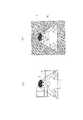
撮像領域分割手段Eによって実行されるステップS11〜ステップS20の処理結果の一例を図15の概念図に示す。
図15中で白抜きで描画された部分がフラグの値として0をセットされたスポットに相当する分割区画つまり人物の撮像領域として規定された分割区画であり、また、図15中にグレーで描画される部分がフラグの値として1をセットされたスポットに相当する分割区画すなわち背景の撮像領域として規定された分割区画である。An example of the processing results of steps S11 to S20 executed by the imaging region dividing means E is shown in the conceptual diagram of FIG.
In FIG. 15, the part drawn in white is a divided section corresponding to a spot in which 0 is set as the flag value, that is, a divided section defined as a person's imaging area, and is drawn in gray in FIG. The portion to be processed is a divided section corresponding to a spot in which 1 is set as a flag value, that is, a divided section defined as a background imaging region.
次いで、コンピュータ2のマイクロプロセッサ12は、フラグの値として0をセットされたスポットに相当する分割区画に含まれる全ての画像データを初期の画像データを記憶するフレームメモリとして機能するRAM15の記憶領域から人物専用のフレームメモリとして機能するRAM15の記憶領域にコピーし(ステップS21)、フラグの値として1をセットされたスポットに相当する分割区画に含まれる全ての画像データを初期の画像データを記憶するフレームメモリとして機能するRAM15の記憶領域から背景専用のフレームメモリとして機能するRAM15の記憶領域にコピーする(ステップS22)。 Next, the
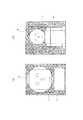
人物専用のフレームメモリとして機能するRAM15の記憶領域にコピーされた画像データの一例を図16(a)に、また、背景専用のフレームメモリとして機能するRAM15の記憶領域にコピーされた画像データの一例を図16(b)に示す。
図16(a)中で白抜きで描画された部分が人物として認識された画像データの集合であり、グレーで表示された部分は実質的な画像データが存在しない部分である。また、図16(b)中でグレーで描画された背景として認識された画像データの集合であり、白抜きで表示された部分は実質的な画像データが存在しない部分である。
なお、図16(a)および図16(b)においては分割区画は記載していない。An example of image data copied to the storage area of the
In FIG. 16 (a), the part drawn in white is a set of image data recognized as a person, and the part displayed in gray is a part where there is no substantial image data. Further, FIG. 16B shows a set of image data recognized as a background drawn in gray, and a portion displayed in white is a portion where no substantial image data exists.
In FIG. 16 (a) and FIG. 16 (b), the divided sections are not shown.
次いで、マスキング手段Fとして機能するコンピュータ2のマイクロプロセッサ12が、背景専用のフレームメモリとして機能するRAM15の記憶領域に記憶された画像データの全て、つまり、撮像領域分割手段Eにより背景の撮像領域として規定された全ての分割区画の画像データ(図16(b)参照)に対してマスキングのための画像処理を施す(ステップS23)。
マスキングのための画像処理は、隠すべき背景となるカレンダーへの書き込みや蔵書の背表紙のタイトル,飾られた賞状等の文字,装飾品や家財道具等を必要な範囲で隠蔽することが可能であればどのようなものでもよく、要求される隠蔽力の程度に応じて、例えば、適度のぼかし,解像度の低下,輝度の変更,コントラストの強調や平準化、また、塗り潰し等といった様々な方法を適用することができる。Next, the
For image processing for masking, it is possible to conceal the writing to the calendar as the background to be hidden, the title of the back cover of the collection, letters such as decorated award certificates, decorations and household goods as far as necessary. Any method can be used, depending on the level of hiding power required, various methods such as moderate blurring, resolution reduction, luminance change, contrast enhancement and leveling, and painting, etc. Can be applied.
次いで、配信用画像データ出力手段Gとして機能するコンピュータ2のマイクロプロセッサ12が、撮像領域分割手段Eにより人物の撮像領域として規定された全ての分割区画の画像データつまり人物専用のフレームメモリとして機能するRAM15の記憶領域に現時点で記憶されている画像データとマスキング手段Fにより画像処理を施された画像データつまり背景専用のフレームメモリとして機能するRAM15の記憶領域に現時点で記憶されている画像データとを合成して配信用の画像データを生成して一時記憶する(ステップS24)。 Next, the
次いで、コンピュータ2のマイクロプロセッサ12が配信用の画像データをディスプレイ22にプレビューとして表示し(ステップS25)、キーボード20もしくはマウス21からの配信許可信号の入力や倍率変更要求の入力あるいは深度変更要求の入力やマスキング方法の再選択要求の入力を待つ待機状態に入る(ステップS26,ステップS27,ステップS29,ステップS31からなるループ処理)。 Next, the
ここで、画像の配信元となるコンピュータ2のユーザはディスプレイ22のプレビューを参照し、表示された顔の大きさが適切であるか否か、隠蔽したい背景が写り込んだり体の輪郭部分がマスキングされたりしてないかどうか、マスキング方法の選択が適切であったか否かを目視にて判断する。 Here, the user of the
表示された顔の大きさが適切でなければユーザはキーボード20もしくはマウス21を操作し、拡大または縮小の倍率変更要求をコンピュータ2に入力する。倍率変更要求の入力はステップS27の判定処理でコンピュータ2のマイクロプロセッサ12により検知され、倍率変更要求を受けたマイクロプロセッサ12がインターフェイス17を介してWebカメラ3にズーミング指令を送出し(ステップS28)、Webカメラ3のマイクロプロセッサ5がズーミング指令の入力を検知し(図10のステップT6)、ズーミング指令の方向性つまりズームアウト指令(縮小)かズームイン指令(拡大)かの種別に応じてズーム機構11を作動させ、カメラ本体10に設けられた撮影レンズの焦点距離を調整することになる(ステップT7)。 If the size of the displayed face is not appropriate, the user operates the
そして、ズーミング指令の送出を終えたコンピュータ2のマイクロプロセッサ12は改めてステップS1の処理に復帰し、前記と同様にしてステップS1〜ステップS24までの処理を繰り返し実行し、最終的に、新たに生成された配信用の画像データつまり顔の大きさを拡大または縮小された配信用の画像データをディスプレイ22に改めてプレビューとして表示する(ステップS25)。 Then, the
以下、この実施形態にあっては、プレビューを参照して行われる手動操作による撮影レンズの焦点距離の調整をズーミングリトライ機能と称する。 Hereinafter, in this embodiment, the adjustment of the focal length of the photographing lens by manual operation performed with reference to the preview is referred to as a zooming retry function.
また、隠蔽したい背景が写り込んだり体の輪郭部分がマスキングされたりしていた場合には、ユーザはキーボード20のテンキー等を操作し、最長離間距離z0の値をモデファイして深度変更要求としてコンピュータ2に入力する。モデファイされた最長離間距離z0の値はステップS29の判定処理でコンピュータ2のマイクロプロセッサ12により検知され、最長離間距離z0の入力を受けたマイクロプロセッサ12が最長離間距離記憶レジスタR(z0)の値を一時的に書き換える(ステップS30)。 If the background to be hidden is reflected or the outline of the body is masked, the user operates the numeric keypad of the
隠蔽したい背景が写り込んでいる場合には、図14からも明らかなように、最長離間距離z0の値が大き過ぎることを意味するので、ユーザは最長離間距離z0の値を相対的に小さな値に設定し直し、また、体の輪郭部分がマスキングされてしまっている場合には、図14からも明らかなように、最長離間距離z0の値が小さ過ぎることを意味するので、ユーザは最長離間距離z0の値を相対的に大きな値に設定し直すことになる。 When the background to be hidden is reflected, as is apparent from FIG. 14, it means that the value of the longest separation distance z0 is too large, so the user sets the value of the longest separation distance z0 to a relatively small value. If the contour of the body has been masked again, as is apparent from FIG. 14, it means that the value of the longest separation distance z0 is too small, so that the user The value of the distance z0 is reset to a relatively large value.
そして、コンピュータ2のマイクロプロセッサ12は改めてステップS11の処理に復帰し、前記と同様にしてステップS11〜ステップS24までの処理を繰り返し実行し、最終的に、変更された最長離間距離z0の値に基いて分離された人物専用のフレームメモリ内の画像データと背景専用のフレーム内の画像データとを合成して得られた配信用の画像データをディスプレイ22に改めてプレビューとして表示する(ステップS25)。 Then, the
以下、この実施形態にあっては、プレビューを参照して手動操作で行われる最長離間距離の調整を撮像深度のリトライ設定機能と称する。 Hereinafter, in this embodiment, the adjustment of the longest separation distance that is manually performed with reference to the preview is referred to as an imaging depth retry setting function.
また、マスキング方法の選択が適切でなかった場合には、ユーザはキーボード20やマウス21を操作し、別のマスキング方法を選んでマスキング方法の再選択要求としてコンピュータ2に入力する。マスキング方法の再選択要求はステップS31の判定処理でコンピュータ2のマイクロプロセッサ12により検知され、マスキング方法の再選択要求を受けたマイクロプロセッサ12は、新たに指定されたマスキング方法を、実行すべきマスキング方法として記憶する(ステップS32)。 If the masking method is not properly selected, the user operates the
この操作は、例えば、隠蔽すべき背景が十分に隠蔽されていないとユーザが判断した場合に背景のぼかしを強くしたり解像度を大きく低下させたり、或いは、ぼかしや解像度の低下では隠蔽が不十分と判断した場合に塗り潰しによるマスキングを利用したりする場合に行なわれる。無論、これとは逆に、背景の隠蔽が十分な範囲でぼかしを緩めたり解像度を上昇させて全体の画面全体の雰囲気を向上させるといった場合もある。 For example, this operation may be performed when the user determines that the background to be concealed is not sufficiently concealed, or the background is strongly blurred or the resolution is greatly reduced, or the blurring or the resolution is not sufficiently concealed. This is performed when masking by filling is used when it is determined. Needless to say, on the contrary, there are also cases where the background is loosened or the resolution is increased to improve the atmosphere of the entire screen as long as the background is sufficiently concealed.
そして、コンピュータ2のマイクロプロセッサ12は改めてステップS23の処理に復帰し、前記と同様にしてステップS23〜ステップS24までの処理を繰り返し実行し、最終的に、再選択されたマスキング方法で作成された背景専用のフレーム内の画像データと人物専用のフレームメモリ内の画像データとを合成して得られた配信用の画像データをディスプレイ22に改めてプレビューとして表示する(ステップS25)。 Then, the
以下、この実施形態にあっては、プレビューを参照して手動操作で行われるマスキング方法の再選択をマスキング方法のリトライ設定機能と称する。 Hereinafter, in this embodiment, reselection of the masking method performed manually by referring to the preview is referred to as a retry setting function of the masking method.
ユーザがキーボード20やマウス21を操作してコンピュータに配信許可信号を入力しない限り、これらのズーミングリトライ機能や撮像深度のリトライ設定機能およびマスキング方法のリトライ設定機能は何度でも繰り返して実行することができる。無論、複数のリトライ機能を組み合わせて実行してもよい。 Unless the user operates the
そして、最終的に、ディスプレイ22のプレビューを参照したユーザが配信用の画像データが適切であると判断し、キーボード20もしくはマウス21を操作してコンピュータ2に配信許可信号を入力すると、コンピュータ2のマイクロプロセッサ12は、配信許可信号の入力をステップS26の判定処理で検知し、まず、1処理周期前すなわち1フレーム前の画像データを一時記憶する過去画像用フレームメモリとして機能するRAM15の記憶領域を一旦初期化する(ステップS33)。 Finally, when the user who refers to the preview of the
次いで、コンピュータ2のマイクロプロセッサ12は、インターフェイス17を介してWebカメラ3に画像取込指令を送出した後(ステップS34)、既に述べた通りの区画別距離データ算出手段Aおよびデータ転送手段として機能するWebカメラ3のマイクロプロセッサ5がステップT2〜ステップT5の処理を実行して画像データや各分割区画毎の最短離間距離のデータを送信してくるまで待機し(ステップS35)、これらのデータを読み込んで初期の画像データを記憶するフレームメモリや最短離間距離のデータを記憶するデータ記憶テーブルとして機能するRAM15に一時記憶する(ステップS36)。 Next, the
そして、撮像領域分割手段Eとして機能するコンピュータ2のマイクロプロセッサ12がステップS11〜ステップステップS20と同等の処理を前記と同様にして繰り返し実行し、最長離間距離算出手段Cとして機能するコンピュータ2のマイクロプロセッサ12が当初に最長離間距離記憶レジスタR(z0)に記憶させた最長離間距離z0の値もしくは撮像深度のリトライ設定機能によって改めて設定された最長離間距離z0の値あるいはズーミングリトライ機能の起動に伴って最長離間距離算出手段Cが改めて最長離間距離記憶レジスタR(z0)に記憶させた最長離間距離z0の値と、区画別距離データ算出手段Aとして機能するWebカメラ3のマイクロプロセッサ5による処理結果としてRAM15のデータ記憶テーブルに記憶された最短離間距z(1,1)〜z(m,n)との大小関係を全て比較して、データ記憶テーブルの(1,1)スポット〜(m,n)スポットに当該分割区画が人物の撮像領域であることを示すフラグの値0または当該分割区画が背景の撮像領域であることを示すフラグの値1をセットし、更に、マスキング手段Fとして機能するコンピュータ2のマイクロプロセッサ12が、ステップS21〜ステップステップS23と同等の処理を前記と同様にして繰り返し実行し、フラグの値として0をセットされたスポットに相当する分割区画に含まれる全ての画像データを、初期の画像データを記憶するフレームメモリとして機能するRAM15の記憶領域から人物専用のフレームメモリとして機能するRAM15の記憶領域にコピーする一方、フラグの値として1をセットされたスポットに相当する分割区画に含まれる全ての画像データを、初期の画像データを記憶するフレームメモリとして機能するRAM15の記憶領域から背景専用のフレームメモリとして機能するRAM15の記憶領域にコピーし、背景専用のフレームメモリとして機能するRAM15の記憶領域に記憶された画像データの全て、つまり、撮像領域分割手段Eにより背景の撮像領域として規定された全ての分割区画の画像データに対してマスキングのための画像処理を施した後、最終的に、配信用画像データ出力手段Gとして機能するコンピュータ2のマイクロプロセッサ12が、撮像領域分割手段Eにより人物の撮像領域として規定された全ての分割区画の画像データつまり人物専用のフレームメモリとして機能するRAM15の記憶領域に現時点で記憶されている画像データとマスキング手段Fにより画像処理を施された画像データつまり背景専用のフレームメモリとして機能するRAM15の記憶領域に現時点で記憶されている画像データとを合成して、配信用の画像データとして一時記憶する(以上、ステップS37の処理)。 Then, the
次いで、配信用画像データ出力手段Gとして機能するコンピュータ2のマイクロプロセッサ12が、現時点で一時記憶されている配信用の画像データつまり前述のステップS37の処理で生成された配信用の画像データとステップS33もしくはステップS39の処理で既に過去画像用フレームメモリとして機能するRAM15の記憶領域に記憶されている画像データとを比較し、両者間の差分となる画像データのみを、インターフェイス18およびネットワーク4を介して、動画の配信対象となる他のコンピュータ2に配信する(ステップS38)。 Next, the
但し、ステップS33の実行直後に実施されるステップ38の処理においては過去画像用フレームメモリがリセットされた状態にあるので、現時点で一時記憶されている配信用の画像データつまり前述のステップS37の処理で生成された配信用の画像データの全てが其のままインターフェイス18およびネットワーク4を介して動画の配信対象となる他のコンピュータ2に配信されることになる。 However, since the past image frame memory is in the reset state in the process of step 38 performed immediately after the execution of step S33, the image data for distribution temporarily stored at the present time, that is, the process of step S37 described above. All of the image data for distribution generated in (1) is distributed as it is to the
次いで、コンピュータ2のマイクロプロセッサ12は、直前のステップS37の処理で生成された画像を過去画像用フレームメモリに上書きするかたちで更新して記憶させる(ステップS39)。 Next, the
そして、コンピュータ2のマイクロプロセッサ12は、ユーザがキーボード20やマウス21を操作して画像の更新頻度つまりフレームレートの調整に関わる指令を入力しているか否か(ステップS40)、画像の解像度の調整に関わる指令を入力しているか否か(ステップS42)、および、画像配信処理の終了を宣言する指令を入力しているか否かを判定し(ステップS44)、何れの指令も入力されていなければ、前記と同様にしてステップS34〜ステップS44の処理を繰り返し実行する。 Then, the
従って、この実施形態にあっては、最長離間距離算出手段Cの作動後つまりステップS10までの処理が行なわれた後に、Webカメラ3の区画別距離データ算出手段AによるステップT2〜ステップT5の処理と、コンピュータ2の撮像領域分割手段Eの処理つまりステップS37の処理のうちステップS11〜ステップS20に相当する処理と、マスキング手段Fの処理つまりステップS37の処理のうちステップS21〜ステップS23に相当する処理と、配信用画像データ出力手段Gによる処理つまりステップS37の処理のうちステップS24に相当する処理とステップS38の処理とが所定周期毎に繰り返し実行されているといって差し支えない。 Therefore, in this embodiment, after the operation of the longest separation distance calculation unit C, that is, after the processing up to step S10 is performed, the processing of steps T2 to T5 by the divisional distance data calculation unit A of the
この実施形態では、特に、配信用画像データ出力手段Gとして機能するコンピュータ2のマイクロプロセッサ12が、その時点で一時記憶されている配信用の画像データつまりステップS37の処理で新たに生成された配信用の画像データとステップS39の処理で既に過去画像用フレームメモリとして機能するRAM15の記憶領域に記憶されている画像データつまり1処理周期前の画像データとを比較し、両者間の差分となる画像データつまり動きのあった部分の画像データのみを動画の配信対象となる他のコンピュータ2に配信するようにしているので、動画の配信に際してネットワーク4やコンピュータ2の負荷が著しく増大するといった不都合を未然に防止することができる。 In this embodiment, in particular, the
また、ズーミングリトライ機能を利用して撮影レンズの焦点距離を調整した場合にはコンピュータ2のマイクロプロセッサ12が改めてステップS1の処理に復帰してステップS1〜ステップS24までの処理を繰り返し実行して目,鼻,口といった特徴点に対応する分割区画の最短離間距離z1を求め、最長離間距離算出手段Cが最長離間距離z0の値を再計算するので、ズーミングリトライ機能を利用して画像上での顔の大きさを変更した場合であっても常に最適な最長離間距離z0の値を利用して背景と人物とを識別することができる。 When the zooming retry function is used to adjust the focal length of the taking lens, the
画像の配信中に画像のカクツキ等が生じてスムーズな画像配信が困難な場合には、ユーザがキーボード20やマウス21を操作して画像の更新頻度つまりフレームレートの調整やソフトウェア上での画像解像度の調整つまり画像データの間引きに関わる指令を入力して調整を行なうことになるが(ステップS40〜ステップS43)、フレームレートの調整や画像データの間引き処理に関しては公知であるので、ここでは特に説明しない。 When smooth image distribution is difficult due to image cracking during image distribution, the user operates the
以上に述べた通り、この実施形態では、Webカメラ3が備えるカメラ本体10の撮像面として機能するCCDの撮像領域をm行n列の細密な区画に論理的に分割し、分割区画となるi=1〜m,j=1〜nの(i,j)スポット毎にWebカメラ3と撮像対象との最短離間距離を求め、Webカメラ3が取得した画像データから撮像対象とされた人物の体の前面側の少なくとも一部、例えば、目,鼻,口といった構成要素を特徴点として認識し、特徴点として認識された撮像領域上の位置に対応する分割区画の最短離間距離z1と、撮像深度の設定値Dすなわち人体の厚みに関わる標準データz2と人物用の撮像空間を撮像深度方向に冗長するための調整値z3とに基いて人物用の撮像空間とする撮像深度方向の最長離間距離z0を求め、最長離間距離z0とi=1〜m,j=1〜nの(i,j)スポットの分割区画毎の最短離間距離z(i,j)の各々との大小関係を比較し、最短離間距離z(i,j)が最長離間距離z0と同等以下である分割区画に値0のフラグをセットして人物の撮像領域として規定し、この分割区画に含まれる全ての画像データを人物専用のフレームメモリとして機能するRAM15の記憶領域に記憶する一方、最短離間距離z(i,j)が最長離間距離z0を越える分割区画に値1のフラグをセットして背景の撮像領域として規定し、この分割区画に含まれる全ての画像データを背景専用のフレームメモリとして機能するRAM15の記憶領域に記憶し、背景専用のフレームメモリとして機能するRAM15に記憶された画像データのみにマスキングのための画像処理を施し、人物専用のフレームメモリとして機能するRAM15の記憶領域に記憶された画像データとマスキングのための画像処理を施された背景専用のフレームメモリに記憶された画像データとを合成して配信用画像データとするようにしている。 As described above, in this embodiment, the imaging area of the CCD that functions as the imaging surface of the
従って、人物が後方に倒れ込むようにして移動したような場合であっても、その移動量が図14に示されるような調整値z3の範囲内であれば、確実に人物の画像を配信し続けることができる。 Therefore, even when the person moves so as to fall backward, if the movement amount is within the adjustment value z3 as shown in FIG. 14, the image of the person is surely continued to be delivered. be able to.
また、色の情報ではなく撮像深度方向の位置情報に基いて人物と背景を識別するようにしているので、色抜けの発生や手動操作によるマスキング領域の設定の煩わしさがなく、格別なハードウェアを追加する必要がないことから、コスト面での問題も発生しない。 In addition, since the person and the background are identified based on the position information in the imaging depth direction instead of the color information, there is no trouble of setting the masking area by the occurrence of color loss or manual operation, and special hardware. Since there is no need to add, there is no cost problem.
しかも、CCDの撮像領域を細密な区画に分割して人物の撮像領域と背景の撮像領域とを論理的に分割しているので、マスキング領域の選択が大雑把となって除去すべき背景の一部が意図せずに表示されるといった不都合が解消され、更には、特徴点よりも前に位置する人物の一部たとえば肘から先といった部分が不用意に省略されるといった不都合もなく、特に、人物と背景を識別する閾値となる最長離間距離z0を最長離間距離算出手段Cによって特定した後、Webカメラ3の区画別距離データ算出手段Aとコンピュータ2の撮像領域分割手段Eとマスキング手段Fと配信用画像データ出力手段Gを繰り返し作動させて連続的に画像を送出する処理つまり動画の配信を行なうようにしているので、人物と背景を分離する撮像領域分割手段Eの処理がリアルタイムで実行されることになり、動画の配信中に人物が移動した場合であっても背景が露出した画像が不用意に配信される恐れがない。 In addition, since the CCD imaging area is divided into fine sections and the person imaging area and the background imaging area are logically divided, the selection of the masking area becomes a rough part of the background to be removed. Inconveniences such as being displayed unintentionally, and there is no inconvenience that a part of the person located before the feature point, such as the part from the elbow, is inadvertently omitted. And the longest separation distance z0 as a threshold for identifying the background is specified by the longest separation distance calculation means C, the section-by-section distance data calculation means A of the
また、配信される画像データはマスキングのための画像処理を施された背景の画像データと人物の画像データとを合成したものであるから、背景の抜けによる違和感の発生といった問題も生じない。 Further, since the image data to be distributed is a combination of the background image data subjected to image processing for masking and the person image data, there is no problem of a sense of incongruity due to missing background.
図17は他の一実施形態の画像配信システムおよび画像配信方法について簡単に示した作用原理図である。 FIG. 17 is an operation principle diagram simply showing an image distribution system and an image distribution method according to another embodiment.
この実施形態では、図17(a)に示されるように、コンピュータ2の前に着座したユーザが両手を開き、肩幅よりも僅かに腕を開いて下方に広げた状態でWebカメラ3を作動させて画像を取得させ、顔と左右の手のひらの位置を色や形によってコンピュータ2に検出させ、顔と左右の手のひらを結ぶ台形状の形を人物の撮像領域Hとして認識し、それ以外の部分を背景の撮像領域Iとして認識するようにしている。 In this embodiment, as shown in FIG. 17 (a), the user sitting in front of the
このような構成を適用した場合には、人物の体系に合わせたマスキングが可能であり、環境や状況に合わせて意図的にマスキングの範囲を広げたり狭めたりすることも可能である。 When such a configuration is applied, masking according to a person's system is possible, and the masking range can be intentionally widened or narrowed according to the environment or situation.
また、直感的・視覚的な操作によって誰でもが簡単に人物の撮像領域Hをコンピュータ2に教示することができるので、操作の利便性が更に向上する。 In addition, since anyone can easily teach the person's imaging region H to the
撮像領域Hをコンピュータ2に教示した後は、ユーザが大きく位置を移動しない限り、自由なポーズで電話会議やチャットを実施することが可能である。 After teaching the imaging area H to the
以上に開示した実施形態の一部または全部は、以下の付記に示す記載によって適切に表現され得るが、発明を実施するための形態や発明の技術思想は、これらのものに制限されるものではない。 A part or all of the embodiment disclosed above can be appropriately expressed by the description shown in the following supplementary notes, but the form for carrying out the invention and the technical idea of the invention are not limited to these. Absent.
また、画像配信プログラムを構成する主プログラムや補助プログラムは非一時的な記録媒体に記憶されてもよい。非一時的な記録媒体としては、例えば、DVD,CD,フラッシュメモリ等のものを利用することができる。これらのプログラムを非一時的な記録媒体に記憶した場合、各プログラムは非一時的な記録媒体からコンピュータ2のマイクロプロセッサ12やWebカメラ3のマイクロプロセッサ5によって読み出され、各々のマイクロプロセッサによって実行されることになる。
既に述べた通り、区画別距離データ算出手段A,特徴点認識手段B,最長離間距離算出手段C,撮像領域分割手段E,マスキング手段F,配信用画像データ出力手段Gの機能実現手段としてコンピュータ2のマイクロプロセッサ12のみを利用することも可能であり、その場合は主プログラムと補助プログラムからなる画像配信プログラムをコンピュータ2にインストールするだけで事足りる。Further, the main program and the auxiliary program constituting the image distribution program may be stored in a non-temporary recording medium. As the non-temporary recording medium, for example, a DVD, CD, flash memory or the like can be used. When these programs are stored in a non-temporary recording medium, each program is read from the non-temporary recording medium by the
As described above, the
〔付記1〕
Webカメラを利用して人物を撮像し、前記Webカメラに接続されたコンピュータおよび前記コンピュータに接続されたネットワークを介して前記人物の画像を他のコンピュータに配信するようにした画像配信システムにおいて、
前記Webカメラの撮像面を形成する撮像領域を細密な区画に分割して各分割区画毎に前記Webカメラと撮像対象との最短離間距離を求める区画別距離データ算出手段と、
前記Webカメラが取得した画像データから撮像対象とされた人物の体の前面側の少なくとも一部を特徴点として認識する特徴点認識手段と、
前記特徴点認識手段により特徴点として認識された撮像領域上の位置に対応する前記分割区画の最短離間距離と撮像深度の設定値に基いて人物用の撮像空間とする撮像深度方向の最長離間距離を求める最長離間距離算出手段と、
前記最長離間距離算出手段によって求められた最長離間距離と前記分割区画毎の最短離間距離の各々を比較し、最短離間距離が最長離間距離と同等以下である分割区画を人物の撮像領域として規定する一方、最短離間距離が最長離間距離を越える分割区画を背景の撮像領域として規定する撮像領域分割手段と、
前記撮像領域分割手段により背景の撮像領域として規定された全ての分割区画の画像データにマスキングのための画像処理を施すマスキング手段と、
前記撮像領域分割手段により人物の撮像領域として規定された全ての分割区画の画像データと前記マスキング手段により画像処理を施された画像データを合成し、配信用画像データとして前記ネットワークに送出する配信用画像データ出力手段を設けたことを特徴とする画像配信システム。[Appendix 1]
In an image distribution system that images a person using a Web camera and distributes the image of the person to another computer via a computer connected to the Web camera and a network connected to the computer.
A section-by-section distance data calculation unit that divides an imaging region forming an imaging surface of the Web camera into fine sections and obtains the shortest separation distance between the Web camera and the imaging target for each divided section;
Feature point recognizing means for recognizing at least a part of the front side of the body of a person to be imaged from the image data acquired by the Web camera as a feature point;
The longest separation distance in the imaging depth direction as the imaging space for the person based on the set value of the shortest separation distance and the imaging depth of the divided section corresponding to the position on the imaging area recognized as the feature point by the feature point recognition means Means for calculating the longest separation distance;
The longest separation distance calculated by the longest separation distance and the shortest separation distance for each of the divided sections are compared, and a divided section whose shortest separation distance is equal to or less than the longest separation distance is defined as an imaging region of a person. On the other hand, an imaging area dividing means for defining a divided section where the shortest separation distance exceeds the longest separation distance as the background imaging area;
Masking means for performing image processing for masking on image data of all divided sections defined as background imaging areas by the imaging area dividing means;
The image data of all the divided sections defined as the person's imaging area by the imaging area dividing unit and the image data subjected to the image processing by the masking unit are combined and sent to the network as distribution image data An image distribution system comprising image data output means.
〔付記2〕
前記最長離間距離算出手段の作動後、前記Webカメラと前記区画別距離データ算出手段と前記撮像領域分割手段と前記マスキング手段と前記配信用画像データ出力手段が所定周期毎に繰り返し作動することを特徴とした付記1記載の画像配信システム。[Appendix 2]
After the operation of the longest separation distance calculation means, the Web camera, the section-specific distance data calculation means, the imaging area division means, the masking means, and the distribution image data output means are repeatedly operated at predetermined intervals. The image distribution system according to
〔付記3〕
前記撮像深度の設定値が、人体の厚みに相当する値によって構成されていることを特徴とする付記1または付記2記載の画像配信システム。[Appendix 3]
The image delivery system according to
〔付記4〕
前記撮像深度の設定値が、人体の厚みに相当する値と人物用の撮像空間を撮像深度方向に冗長するための調整値によって構成されていることを特徴とする付記1または付記2記載の画像配信システム。[Appendix 4]
The image according to
〔付記5〕
Webカメラを利用して人物を撮像し、前記Webカメラに接続されたコンピュータおよび前記コンピュータに接続されたネットワークを介して前記人物の画像を他のコンピュータに配信するようにした画像配信方法において、
前記Webカメラの撮像面を形成する撮像領域を細密な区画に分割して各分割区画毎に前記Webカメラと撮像対象との最短離間距離を求め、
前記Webカメラが取得した画像データから撮像対象とされた人物の体の前面側の少なくとも一部を特徴点として認識し、
前記特徴点として認識された撮像領域上の位置に対応する前記分割区画の最短離間距離と撮像深度の設定値に基いて人物用の撮像空間とする撮像深度方向の最長離間距離を求め、
前記最長離間距離と前記分割区画毎の最短離間距離の各々を比較し、最短離間距離が最長離間距離と同等以下である分割区画を人物の撮像領域として規定する一方、最短離間距離が最長離間距離を越える分割区画を背景の撮像領域として規定し、
背景の撮像領域として規定された全ての分割区画の画像データにマスキングのための画像処理を施し、
人物の撮像領域として規定された全ての分割区画の画像データと前記画像処理を施された画像データを合成し、配信用画像データとして前記ネットワークに送出することを特徴とした画像配信方法。[Appendix 5]
In an image distribution method for capturing an image of a person using a Web camera and distributing the image of the person to another computer via a computer connected to the Web camera and a network connected to the computer.
The imaging area forming the imaging surface of the Web camera is divided into fine sections, and the shortest separation distance between the Web camera and the imaging target is obtained for each divided section,
Recognizing at least a part of the front side of a person's body as an imaging target from image data acquired by the Web camera as a feature point;
Finding the longest separation distance in the imaging depth direction as the imaging space for a person based on the shortest separation distance and imaging depth setting value corresponding to the position on the imaging region recognized as the feature point,
Comparing each of the longest separation distance and the shortest separation distance for each of the divided sections, and defining a divided section whose shortest separation distance is equal to or less than the longest separation distance as a human imaging region, the shortest separation distance is the longest separation distance. Stipulates the divided area exceeding the
Image processing for masking is applied to the image data of all the divided sections defined as the background imaging area,
An image distribution method comprising: combining image data of all divided sections defined as an image area of a person and image data subjected to the image processing, and transmitting the image data as distribution image data to the network.
〔付記6〕
Webカメラを利用して人物を撮像し、前記Webカメラに接続されたコンピュータおよび前記コンピュータに接続されたネットワークを介して前記人物の画像を他のコンピュータに配信するようにした画像配信方法において、
前記Webカメラの撮像面を形成する撮像領域を細密な区画に分割して各分割区画毎に前記Webカメラと撮像対象との最短離間距離を求め、
前記Webカメラが取得した画像データから撮像対象とされた人物の体の前面側の少なくとも一部を特徴点として認識し、
前記特徴点として認識された撮像領域上の位置に対応する前記分割区画の最短離間距離と撮像深度の設定値に基いて人物用の撮像空間とする撮像深度方向の最長離間距離を求めた後、
前記Webカメラを利用して人物を撮像する操作と、
前記Webカメラの撮像面を形成する撮像領域を細密な区画に分割して各分割区画毎に前記Webカメラと撮像対象との最短離間距離を求める操作と、
前記最長離間距離と前記分割区画毎の最短離間距離の各々を比較し、最短離間距離が最長離間距離と同等以下である分割区画を人物の撮像領域として規定する一方、最短離間距離が最長離間距離を越える分割区画を背景の撮像領域として規定する操作と、
背景の撮像領域として規定された全ての分割区画の画像データにマスキングのための画像処理を施す操作と、
人物の撮像領域として規定された全ての分割区画の画像データと前記画像処理を施された画像データを合成し、配信用画像データとして前記ネットワークに送出する操作を所定周期毎に繰り返し実行することを特徴とした画像配信方法。[Appendix 6]
In an image distribution method for capturing an image of a person using a Web camera and distributing the image of the person to another computer via a computer connected to the Web camera and a network connected to the computer.
The imaging area forming the imaging surface of the Web camera is divided into fine sections, and the shortest separation distance between the Web camera and the imaging target is obtained for each divided section,
Recognizing at least a part of the front side of a person's body as an imaging target from image data acquired by the Web camera as a feature point;
After obtaining the longest separation distance in the imaging depth direction as the imaging space for a person based on the setting value of the shortest separation distance and the imaging depth of the divided section corresponding to the position on the imaging region recognized as the feature point,
An operation of taking an image of a person using the Web camera;
An operation of dividing an imaging region forming an imaging surface of the Web camera into fine sections and obtaining a shortest separation distance between the Web camera and the imaging target for each divided section;
Comparing each of the longest separation distance and the shortest separation distance for each of the divided sections, and defining a divided section whose shortest separation distance is equal to or less than the longest separation distance as a human imaging region, the shortest separation distance is the longest separation distance. An operation for defining a divided section exceeding the background imaging area;
An operation for performing image processing for masking on the image data of all the divided sections defined as the background imaging region;
The operation of combining the image data of all the divided sections defined as the person's imaging area and the image data subjected to the image processing and repeatedly sending the data to the network as distribution image data is executed at predetermined intervals. A featured image delivery method.
〔付記7〕
前記撮像深度の設定値を、人体の厚みに相当する値によって決めることを特徴とした付記5または付記6記載の画像配信方法。[Appendix 7]
The image delivery method according to
〔付記8〕
前記撮像深度の設定値を、人体の厚みに相当する値と人物用の撮像空間を撮像深度方向に冗長するための調整値によって決めることを特徴とした付記5または付記6記載の画像配信方法。[Appendix 8]
The image distribution method according to
〔付記9〕
Webカメラを利用して人物を撮像し、前記Webカメラに接続されたコンピュータおよび前記コンピュータに接続されたネットワークを介して前記人物の画像を他のコンピュータに配信するようにした画像配信システムに用いる画像配信プログラムであって、
前記Webカメラに実装されたマイクロプロセッサを、
前記Webカメラの撮像面を形成する撮像領域を細密な区画に分割して各分割区画毎に前記Webカメラと撮像対象との最短離間距離を求める区画別距離データ算出手段、および、
前記Webカメラで取得された画像データと前記区画別距離データ算出手段で求められた各分割区画毎の最短離間距離を前記Webカメラに接続された前記コンピュータに転送するデータ転送手段として機能させる補助プログラムと、
前記Webカメラに接続されたコンピュータのマイクロプロセッサを、
前記Webカメラが取得した画像データから撮像対象とされた人物の体の前面側の少なくとも一部を特徴点として認識する特徴点認識手段、
前記特徴点認識手段により特徴点として認識された撮像領域上の位置に対応する前記分割区画の最短離間距離と撮像深度の設定値に基いて人物用の撮像空間とする撮像深度方向の最長離間距離を求める最長離間距離算出手段、
前記最長離間距離算出手段によって求められた最長離間距離と前記分割区画毎の最短離間距離の各々を比較し、最短離間距離が最長離間距離と同等以下である分割区画を人物の撮像領域として規定する一方、最短離間距離が最長離間距離を越える分割区画を背景の撮像領域として規定する撮像領域分割手段、
前記撮像領域分割手段により背景の撮像領域として規定された全ての分割区画の画像データにマスキングのための画像処理を施すマスキング手段、および、
前記撮像領域分割手段により人物の撮像領域として規定された全ての分割区画の画像データと前記マスキング手段により画像処理を施された画像データを合成し、配信用画像データとして前記ネットワークに送出する配信用画像データ出力手段として機能させる主プログラムによって構成される画像配信プログラム。[Appendix 9]
An image used for an image distribution system that images a person using a Web camera and distributes the image of the person to another computer via a computer connected to the Web camera and a network connected to the computer. A distribution program,
A microprocessor mounted on the web camera;
A section-by-section distance data calculation unit that divides an imaging region that forms an imaging surface of the Web camera into fine sections and obtains the shortest separation distance between the Web camera and the imaging target for each divided section; and
Auxiliary program that functions as data transfer means for transferring the image data acquired by the Web camera and the shortest separation distance for each divided section obtained by the section-specific distance data calculation means to the computer connected to the Web camera When,
A microprocessor of a computer connected to the web camera;
Feature point recognizing means for recognizing at least a part of the front side of the body of a person to be imaged from the image data acquired by the Web camera as a feature point;
The longest separation distance in the imaging depth direction as the imaging space for the person based on the set value of the shortest separation distance and the imaging depth of the divided section corresponding to the position on the imaging area recognized as the feature point by the feature point recognition means Means for calculating the longest separation distance,
The longest separation distance calculated by the longest separation distance and the shortest separation distance for each of the divided sections are compared, and a divided section whose shortest separation distance is equal to or less than the longest separation distance is defined as an imaging region of a person. On the other hand, an imaging area dividing means for defining a divided section where the shortest separation distance exceeds the longest separation distance as a background imaging area;
Masking means for performing image processing for masking on image data of all divided sections defined as background imaging areas by the imaging area dividing means; and
The image data of all the divided sections defined as the person's imaging area by the imaging area dividing unit and the image data subjected to the image processing by the masking unit are combined and sent to the network as distribution image data An image distribution program constituted by a main program that functions as image data output means.
〔付記10〕
前記主プログラムは、前記最長離間距離算出手段の作動後、前記Webカメラと前記区画別距離データ算出手段と前記撮像領域分割手段と前記マスキング手段と前記配信用画像データ出力手段を所定周期毎に繰り返し作動させるように構成されていることを特徴とした付記9記載の画像配信プログラム。[Appendix 10]
After the operation of the longest separation distance calculation means, the main program repeats the Web camera, the section-specific distance data calculation means, the imaging area division means, the masking means, and the distribution image data output means at predetermined intervals. The image delivery program according to
〔付記11〕
Webカメラを利用して人物を撮像し、前記Webカメラに接続されたコンピュータおよび前記コンピュータに接続されたネットワークを介して前記人物の画像を他のコンピュータに配信するようにした画像配信システムに用いる画像配信プログラムであって、
前記Webカメラに接続されたコンピュータのマイクロプロセッサを、
前記Webカメラの撮像面を形成する撮像領域を細密な区画に分割して各分割区画毎に前記Webカメラと撮像対象との最短離間距離を求める区画別距離データ算出手段、
前記Webカメラが取得した画像データから撮像対象とされた人物の体の前面側の少なくとも一部を特徴点として認識する特徴点認識手段、
前記特徴点認識手段により特徴点として認識された撮像領域上の位置に対応する前記分割区画の最短離間距離と撮像深度の設定値に基いて人物用の撮像空間とする撮像深度方向の最長離間距離を求める最長離間距離算出手段、
前記最長離間距離算出手段によって求められた最長離間距離と前記分割区画毎の最短離間距離の各々を比較し、最短離間距離が最長離間距離と同等以下である分割区画を人物の撮像領域として規定する一方、最短離間距離が最長離間距離を越える分割区画を背景の撮像領域として規定する撮像領域分割手段、
前記撮像領域分割手段により背景の撮像領域として規定された全ての分割区画の画像データにマスキングのための画像処理を施すマスキング手段、および、
前記撮像領域分割手段により人物の撮像領域として規定された全ての分割区画の画像データと前記マスキング手段により画像処理を施された画像データを合成し、配信用画像データとして前記ネットワークに送出する配信用画像データ出力手段として機能させることを特徴とした画像配信プログラム。[Appendix 11]
An image used for an image distribution system that images a person using a Web camera and distributes the image of the person to another computer via a computer connected to the Web camera and a network connected to the computer. A distribution program,
A microprocessor of a computer connected to the web camera;
A section-by-section distance data calculation unit that divides an imaging region that forms an imaging surface of the Web camera into fine sections and obtains the shortest separation distance between the Web camera and the imaging target for each divided section;
Feature point recognizing means for recognizing at least a part of the front side of the body of a person to be imaged from the image data acquired by the Web camera as a feature point;
The longest separation distance in the imaging depth direction as the imaging space for the person based on the set value of the shortest separation distance and the imaging depth of the divided section corresponding to the position on the imaging area recognized as the feature point by the feature point recognition means Means for calculating the longest separation distance,
The longest separation distance calculated by the longest separation distance and the shortest separation distance for each of the divided sections are compared, and a divided section whose shortest separation distance is equal to or less than the longest separation distance is defined as an imaging region of a person. On the other hand, an imaging area dividing means for defining a divided section where the shortest separation distance exceeds the longest separation distance as a background imaging area;
Masking means for performing image processing for masking on image data of all divided sections defined as background imaging areas by the imaging area dividing means; and
The image data of all the divided sections defined as the person's imaging area by the imaging area dividing unit and the image data subjected to the image processing by the masking unit are combined and sent to the network as distribution image data An image distribution program that functions as image data output means.
〔付記12〕
前記最長離間距離算出手段の作動後、前記Webカメラと前記区画別距離データ算出手段と前記撮像領域分割手段と前記マスキング手段と前記配信用画像データ出力手段を所定周期毎に繰り返し作動させるようにしたことを特徴とした付記11記載の画像配信プログラム。[Appendix 12]
After the operation of the longest separation distance calculation means, the Web camera, the section-by-compartment distance data calculation means, the imaging region division means, the masking means, and the distribution image data output means are repeatedly operated at predetermined intervals. The image delivery program according to
本発明は、テレビ会議システム,一般家庭内のテレビ電話,カメラを利用した通信教育,家電のビデオカメラや携帯電話等で撮像された画像を人物と背景に分離する際に利用できる。 INDUSTRIAL APPLICABILITY The present invention can be used when a video conference system, a video phone in a general home, distance learning using a camera, and an image captured by a video camera or a mobile phone of a home appliance are separated into a person and a background.
1 画像配信システム
2 コンピュータ
3 Webカメラ
4 ネットワーク
5 マイクロプロセッサ(区画別距離データ算出手段,データ転送手段)
6 ROM
7 RAM
8 インターフェイス
9 入出力回路
10 カメラ本体
11 ズーム機構
12 マイクロプロセッサ(特徴点認識手段,最長離間距離算出手段,撮像領域分割手段,マスキング手段,配信用画像データ出力手段)
13 ROM
14 不揮発性メモリ
15 RAM
16 ハードディスクドライブ
17 インターフェイス
18 インターフェイス
19 入出力回路
20 キーボード
21 マウス
22 ディスプレイ
23 ドライブ
A 区画別距離データ算出手段
B 特徴点認識手段
C 最長離間距離算出手段
D 撮像深度の設定値
E 撮像領域分割手段
F マスキング手段
G 配信用画像データ出力手段
H 人物
I 背景DESCRIPTION OF
6 ROM
7 RAM
8
13 ROM
14
16
Claims (6)
Translated fromJapanese前記Webカメラの撮像面を形成する撮像領域を細密な区画に分割して各分割区画毎に前記Webカメラと撮像対象との最短離間距離を求める区画別距離データ算出手段と、
前記Webカメラが取得した画像データから撮像対象とされた人物の体の前面側の少なくとも一部を特徴点として認識する特徴点認識手段と、
前記特徴点認識手段により特徴点として認識された撮像領域上の位置に対応する前記分割区画の最短離間距離と人体の厚みに相当する値および人物用の撮像空間を撮像深度方向に冗長するための調整値からなる撮像深度の設定値に基いて人物用の撮像空間とする撮像深度方向の最長離間距離を求める最長離間距離算出手段と、
前記最長離間距離算出手段によって求められた最長離間距離と前記分割区画毎の最短離間距離の各々を比較し、最短離間距離が最長離間距離と同等以下である分割区画を人物の撮像領域として規定する一方、最短離間距離が最長離間距離を越える分割区画を背景の撮像領域として規定する撮像領域分割手段と、
前記撮像領域分割手段により背景の撮像領域として規定された全ての分割区画の画像データにマスキングのための画像処理を施すマスキング手段と、
前記撮像領域分割手段により人物の撮像領域として規定された全ての分割区画の画像データと前記マスキング手段により画像処理を施された画像データを合成し、配信用画像データとして前記ネットワークに送出する配信用画像データ出力手段を設けたことを特徴とする画像配信システム。In an image distribution system that images a person using a Web camera and distributes the image of the person to another computer via a computer connected to the Web camera and a network connected to the computer.
A section-by-section distance data calculation unit that divides an imaging region forming an imaging surface of the Web camera into fine sections and obtains the shortest separation distance between the Web camera and the imaging target for each divided section;
Feature point recognizing means for recognizing at least a part of the front side of the body of a person to be imaged from the image data acquired by the Web camera as a feature point;
A value corresponding to the shortest separation distance andthe thickness of the human body corresponding to the position on the imaging region recognized as a feature point by the feature point recognition unit and ahuman imaging space for redundancy in the imaging depth direction A longest separation distance calculating means for obtaining a longest separation distance in the imaging depth direction as an imaging space for a person based on a setting value of an imaging depth formed of anadjustment value ;
The longest separation distance calculated by the longest separation distance and the shortest separation distance for each of the divided sections are compared, and a divided section whose shortest separation distance is equal to or less than the longest separation distance is defined as an imaging region of a person. On the other hand, an imaging area dividing means for defining a divided section where the shortest separation distance exceeds the longest separation distance as the background imaging area;
Masking means for performing image processing for masking on image data of all divided sections defined as background imaging areas by the imaging area dividing means;
The image data of all the divided sections defined as the person's imaging area by the imaging area dividing unit and the image data subjected to the image processing by the masking unit are combined and sent to the network as distribution image data An image distribution system comprising image data output means.
前記Webカメラの撮像面を形成する撮像領域を細密な区画に分割して各分割区画毎に前記Webカメラと撮像対象との最短離間距離を求め、
前記Webカメラが取得した画像データから撮像対象とされた人物の体の前面側の少なくとも一部を特徴点として認識し、
前記特徴点として認識された撮像領域上の位置に対応する前記分割区画の最短離間距離と人体の厚みに相当する値および人物用の撮像空間を撮像深度方向に冗長するための調整値からなる撮像深度の設定値に基いて人物用の撮像空間とする撮像深度方向の最長離間距離を求め、
前記最長離間距離と前記分割区画毎の最短離間距離の各々を比較し、最短離間距離が最長離間距離と同等以下である分割区画を人物の撮像領域として規定する一方、最短離間距離が最長離間距離を越える分割区画を背景の撮像領域として規定し、
背景の撮像領域として規定された全ての分割区画の画像データにマスキングのための画像処理を施し、
人物の撮像領域として規定された全ての分割区画の画像データと前記画像処理を施された画像データを合成し、配信用画像データとして前記ネットワークに送出することを特徴とした画像配信方法。In an image distribution method for capturing an image of a person using a Web camera and distributing the image of the person to another computer via a computer connected to the Web camera and a network connected to the computer.
The imaging area forming the imaging surface of the Web camera is divided into fine sections, and the shortest separation distance between the Web camera and the imaging target is obtained for each divided section,
Recognizing at least a part of the front side of a person's body as an imaging target from image data acquired by the Web camera as a feature point;
Imagingconsisting of a value corresponding to the shortest separation distance of the divided sections andthe thickness of the human body corresponding to the position on the imaging region recognized as the feature point,and an adjustment value for making the imaging space for the person redundant in the imaging depth direction Based on the depth setting value, find the longest separation distance in the imaging depth direction as the imaging space for people,
Comparing each of the longest separation distance and the shortest separation distance for each of the divided sections, and defining a divided section whose shortest separation distance is equal to or less than the longest separation distance as a human imaging region, the shortest separation distance is the longest separation distance. Stipulates the divided area exceeding the
Image processing for masking is applied to the image data of all the divided sections defined as the background imaging area,
An image distribution method comprising: combining image data of all divided sections defined as an image area of a person and image data subjected to the image processing, and transmitting the image data as distribution image data to the network.
前記Webカメラの撮像面を形成する撮像領域を細密な区画に分割して各分割区画毎に前記Webカメラと撮像対象との最短離間距離を求め、
前記Webカメラが取得した画像データから撮像対象とされた人物の体の前面側の少なくとも一部を特徴点として認識し、
前記特徴点として認識された撮像領域上の位置に対応する前記分割区画の最短離間距離と人体の厚みに相当する値および人物用の撮像空間を撮像深度方向に冗長するための調整値からなる撮像深度の設定値に基いて人物用の撮像空間とする撮像深度方向の最長離間距離を求めた後、
前記Webカメラを利用して人物を撮像する操作と、
前記Webカメラの撮像面を形成する撮像領域を細密な区画に分割して各分割区画毎に前記Webカメラと撮像対象との最短離間距離を求める操作と、
前記最長離間距離と前記分割区画毎の最短離間距離の各々を比較し、最短離間距離が最長離間距離と同等以下である分割区画を人物の撮像領域として規定する一方、最短離間距離が最長離間距離を越える分割区画を背景の撮像領域として規定する操作と、
背景の撮像領域として規定された全ての分割区画の画像データにマスキングのための画像処理を施す操作と、
人物の撮像領域として規定された全ての分割区画の画像データと前記画像処理を施された画像データを合成し、配信用画像データとして前記ネットワークに送出する操作を所定周期毎に繰り返し実行することを特徴とした画像配信方法。In an image distribution method for capturing an image of a person using a Web camera and distributing the image of the person to another computer via a computer connected to the Web camera and a network connected to the computer.
The imaging area forming the imaging surface of the Web camera is divided into fine sections, and the shortest separation distance between the Web camera and the imaging target is obtained for each divided section,
Recognizing at least a part of the front side of a person's body as an imaging target from image data acquired by the Web camera as a feature point;
Imagingconsisting of a value corresponding to the shortest separation distance of the divided sections andthe thickness of the human body corresponding to the position on the imaging region recognized as the feature point,and an adjustment value for making the imaging space for the person redundant in the imaging depth direction After obtaining the longest separation distance in the imaging depth direction as the human imaging space based on the depth setting value,
An operation of taking an image of a person using the Web camera;
An operation of dividing an imaging region forming an imaging surface of the Web camera into fine sections and obtaining a shortest separation distance between the Web camera and the imaging target for each divided section;
Comparing each of the longest separation distance and the shortest separation distance for each of the divided sections, and defining a divided section whose shortest separation distance is equal to or less than the longest separation distance as a human imaging region, the shortest separation distance is the longest separation distance. An operation for defining a divided section exceeding the background imaging area;
An operation for performing image processing for masking on the image data of all the divided sections defined as the background imaging region;
The operation of combining the image data of all the divided sections defined as the person's imaging area and the image data subjected to the image processing and repeatedly sending the data to the network as distribution image data is executed at predetermined intervals. A featured image delivery method.
前記Webカメラに実装されたマイクロプロセッサを、
前記Webカメラの撮像面を形成する撮像領域を細密な区画に分割して各分割区画毎に前記Webカメラと撮像対象との最短離間距離を求める区画別距離データ算出手段、および、
前記Webカメラで取得された画像データと前記区画別距離データ算出手段で求められた各分割区画毎の最短離間距離を前記Webカメラに接続された前記コンピュータに転送するデータ転送手段として機能させる補助プログラムと、
前記Webカメラに接続されたコンピュータのマイクロプロセッサを、
前記Webカメラが取得した画像データから撮像対象とされた人物の体の前面側の少なくとも一部を特徴点として認識する特徴点認識手段、
前記特徴点認識手段により特徴点として認識された撮像領域上の位置に対応する前記分割区画の最短離間距離と人体の厚みに相当する値および人物用の撮像空間を撮像深度方向に冗長するための調整値からなる撮像深度の設定値に基いて人物用の撮像空間とする撮像深度方向の最長離間距離を求める最長離間距離算出手段、
前記最長離間距離算出手段によって求められた最長離間距離と前記分割区画毎の最短離間距離の各々を比較し、最短離間距離が最長離間距離と同等以下である分割区画を人物の撮像領域として規定する一方、最短離間距離が最長離間距離を越える分割区画を背景の撮像領域として規定する撮像領域分割手段、
前記撮像領域分割手段により背景の撮像領域として規定された全ての分割区画の画像データにマスキングのための画像処理を施すマスキング手段、および、
前記撮像領域分割手段により人物の撮像領域として規定された全ての分割区画の画像データと前記マスキング手段により画像処理を施された画像データを合成し、配信用画像データとして前記ネットワークに送出する配信用画像データ出力手段として機能させる主プログラムによって構成される画像配信プログラム。An image used for an image distribution system that images a person using a Web camera and distributes the image of the person to another computer via a computer connected to the Web camera and a network connected to the computer. A distribution program,
A microprocessor mounted on the web camera;
A section-by-section distance data calculation unit that divides an imaging region that forms an imaging surface of the Web camera into fine sections and obtains the shortest separation distance between the Web camera and the imaging target for each divided section; and
Auxiliary program that functions as data transfer means for transferring the image data acquired by the Web camera and the shortest separation distance for each divided section obtained by the section-specific distance data calculation means to the computer connected to the Web camera When,
A microprocessor of a computer connected to the web camera;
Feature point recognizing means for recognizing at least a part of the front side of the body of a person to be imaged from the image data acquired by the Web camera as a feature point;
A value corresponding to the shortest separation distance andthe thickness of the human body corresponding to the position on the imaging region recognized as a feature point by the feature point recognition unit and ahuman imaging space for redundancy in the imaging depth direction A longest separation distance calculating means for obtaining a longest separation distance in the imaging depth direction to be an imaging space for a person based on a setting value of an imaging depthcomposed of an adjustment value ;
The longest separation distance calculated by the longest separation distance and the shortest separation distance for each of the divided sections are compared, and a divided section whose shortest separation distance is equal to or less than the longest separation distance is defined as an imaging region of a person. On the other hand, an imaging area dividing means for defining a divided section where the shortest separation distance exceeds the longest separation distance as a background imaging area;
Masking means for performing image processing for masking on image data of all divided sections defined as background imaging areas by the imaging area dividing means; and
The image data of all the divided sections defined as the person's imaging area by the imaging area dividing unit and the image data subjected to the image processing by the masking unit are combined and sent to the network as distribution image data An image distribution program constituted by a main program that functions as image data output means.
Priority Applications (1)
| Application Number | Priority Date | Filing Date | Title |
|---|---|---|---|
| JP2010237019AJP5263989B2 (en) | 2010-10-22 | 2010-10-22 | Image delivery system, image delivery method, and image delivery program |
Applications Claiming Priority (1)
| Application Number | Priority Date | Filing Date | Title |
|---|---|---|---|
| JP2010237019AJP5263989B2 (en) | 2010-10-22 | 2010-10-22 | Image delivery system, image delivery method, and image delivery program |
Publications (2)
| Publication Number | Publication Date |
|---|---|
| JP2012090197A JP2012090197A (en) | 2012-05-10 |
| JP5263989B2true JP5263989B2 (en) | 2013-08-14 |
Family
ID=46261306
Family Applications (1)
| Application Number | Title | Priority Date | Filing Date |
|---|---|---|---|
| JP2010237019AExpired - Fee RelatedJP5263989B2 (en) | 2010-10-22 | 2010-10-22 | Image delivery system, image delivery method, and image delivery program |
Country Status (1)
| Country | Link |
|---|---|
| JP (1) | JP5263989B2 (en) |
Families Citing this family (1)
| Publication number | Priority date | Publication date | Assignee | Title |
|---|---|---|---|---|
| CN107680128B (en)* | 2017-10-31 | 2020-03-27 | Oppo广东移动通信有限公司 | Image processing method, image processing device, electronic equipment and computer readable storage medium |
Family Cites Families (6)
| Publication number | Priority date | Publication date | Assignee | Title |
|---|---|---|---|---|
| JP3752510B2 (en)* | 1996-04-15 | 2006-03-08 | イーストマン コダック カンパニー | Automatic subject detection method for images |
| JP2004172862A (en)* | 2002-11-19 | 2004-06-17 | Megachips System Solutions Inc | Image composition method and composite image delivery system |
| JP4670303B2 (en)* | 2004-10-06 | 2011-04-13 | ソニー株式会社 | Image processing method and image processing apparatus |
| JP2009027298A (en)* | 2007-07-18 | 2009-02-05 | Ricoh Co Ltd | IMAGING DEVICE AND IMAGING DEVICE CONTROL METHOD |
| JP5088161B2 (en)* | 2008-02-15 | 2012-12-05 | ソニー株式会社 | Image processing apparatus, camera apparatus, communication system, image processing method, and program |
| JP5272775B2 (en)* | 2009-02-12 | 2013-08-28 | 株式会社ニコン | Electronic still camera |
- 2010
- 2010-10-22JPJP2010237019Apatent/JP5263989B2/ennot_activeExpired - Fee Related
Also Published As
| Publication number | Publication date |
|---|---|
| JP2012090197A (en) | 2012-05-10 |
Similar Documents
| Publication | Publication Date | Title |
|---|---|---|
| JP5384190B2 (en) | Method and apparatus for performing touch adjustment in an imaging device | |
| KR101608556B1 (en) | Information display apparatus and information display method | |
| JP6525617B2 (en) | Image processing apparatus and control method thereof | |
| US8441567B2 (en) | Digital photographing apparatus and method of controlling the same | |
| CN102957860B (en) | The method of image processing equipment and processing image | |
| JP5835383B2 (en) | Information processing method, information processing apparatus, and program | |
| JP5835384B2 (en) | Information processing method, information processing apparatus, and program | |
| WO2021175269A1 (en) | Image processing method and mobile terminal | |
| JP5760324B2 (en) | Image processing apparatus, image processing method, image processing program, and recording medium on which the image processing program is recorded | |
| US20110019239A1 (en) | Image Reproducing Apparatus And Image Sensing Apparatus | |
| US20060078224A1 (en) | Image combination device, image combination method, image combination program, and recording medium containing the image combination program | |
| US20090251557A1 (en) | Image pickup control method and apparatus for camera | |
| JP2007184683A (en) | Image data processing apparatus and method | |
| CN103888684B (en) | Image processing apparatus, image processing method and recording medium | |
| JP2022027841A (en) | Electronic apparatus, program, and storage medium | |
| CN114785969B (en) | Shooting method and device | |
| JP2019075771A (en) | Electronic device and control method of the same | |
| JP2017084422A (en) | Device, method, and program | |
| JP5263989B2 (en) | Image delivery system, image delivery method, and image delivery program | |
| JP3983623B2 (en) | Image composition apparatus, image composition method, image composition program, and recording medium on which image composition program is recorded | |
| JP6583486B2 (en) | Information processing method, information processing program, and information processing apparatus | |
| JP6777208B2 (en) | program | |
| JP6128185B2 (en) | Apparatus, method, and program | |
| JP5623247B2 (en) | Imaging apparatus and control method thereof | |
| JP6925827B2 (en) | Image processing device and image processing method |
Legal Events
| Date | Code | Title | Description |
|---|---|---|---|
| A977 | Report on retrieval | Free format text:JAPANESE INTERMEDIATE CODE: A971007 Effective date:20121206 | |
| A131 | Notification of reasons for refusal | Free format text:JAPANESE INTERMEDIATE CODE: A131 Effective date:20130108 | |
| A521 | Request for written amendment filed | Free format text:JAPANESE INTERMEDIATE CODE: A523 Effective date:20130304 | |
| TRDD | Decision of grant or rejection written | ||
| A01 | Written decision to grant a patent or to grant a registration (utility model) | Free format text:JAPANESE INTERMEDIATE CODE: A01 Effective date:20130402 | |
| A61 | First payment of annual fees (during grant procedure) | Free format text:JAPANESE INTERMEDIATE CODE: A61 Effective date:20130426 | |
| R150 | Certificate of patent or registration of utility model | Ref document number:5263989 Country of ref document:JP Free format text:JAPANESE INTERMEDIATE CODE: R150 Free format text:JAPANESE INTERMEDIATE CODE: R150 | |
| S111 | Request for change of ownership or part of ownership | Free format text:JAPANESE INTERMEDIATE CODE: R313111 | |
| R350 | Written notification of registration of transfer | Free format text:JAPANESE INTERMEDIATE CODE: R350 | |
| LAPS | Cancellation because of no payment of annual fees |