JP5262785B2 - Non-contact power transmission device - Google Patents
Non-contact power transmission deviceDownload PDFInfo
- Publication number
- JP5262785B2 JP5262785B2JP2009027670AJP2009027670AJP5262785B2JP 5262785 B2JP5262785 B2JP 5262785B2JP 2009027670 AJP2009027670 AJP 2009027670AJP 2009027670 AJP2009027670 AJP 2009027670AJP 5262785 B2JP5262785 B2JP 5262785B2
- Authority
- JP
- Japan
- Prior art keywords
- coil
- primary
- load
- resonance coil
- power transmission
- Prior art date
- Legal status (The legal status is an assumption and is not a legal conclusion. Google has not performed a legal analysis and makes no representation as to the accuracy of the status listed.)
- Expired - Fee Related
Links
- 230000005540biological transmissionEffects0.000titleclaimsdescription90
- 238000005259measurementMethods0.000claimsdescription11
- RYGMFSIKBFXOCR-UHFFFAOYSA-NCopperChemical compound[Cu]RYGMFSIKBFXOCR-UHFFFAOYSA-N0.000description12
- 239000003990capacitorSubstances0.000description7
- 238000010586diagramMethods0.000description4
- 229910052802copperInorganic materials0.000description3
- 239000010949copperSubstances0.000description3
- 230000000694effectsEffects0.000description3
- 230000005672electromagnetic fieldEffects0.000description3
- 238000012546transferMethods0.000description3
- XAGFODPZIPBFFR-UHFFFAOYSA-NaluminiumChemical compound[Al]XAGFODPZIPBFFR-UHFFFAOYSA-N0.000description1
- 229910052782aluminiumInorganic materials0.000description1
- -1and for exampleChemical compound0.000description1
- 238000004891communicationMethods0.000description1
- 230000007423decreaseEffects0.000description1
- 230000005674electromagnetic inductionEffects0.000description1
- 238000002474experimental methodMethods0.000description1
- 238000002847impedance measurementMethods0.000description1
- 239000000463materialSubstances0.000description1
- 229910052709silverInorganic materials0.000description1
- 239000004332silverSubstances0.000description1
- 238000012360testing methodMethods0.000description1
- 238000004804windingMethods0.000description1
Images


Classifications
- B—PERFORMING OPERATIONS; TRANSPORTING
- B60—VEHICLES IN GENERAL
- B60L—PROPULSION OF ELECTRICALLY-PROPELLED VEHICLES; SUPPLYING ELECTRIC POWER FOR AUXILIARY EQUIPMENT OF ELECTRICALLY-PROPELLED VEHICLES; ELECTRODYNAMIC BRAKE SYSTEMS FOR VEHICLES IN GENERAL; MAGNETIC SUSPENSION OR LEVITATION FOR VEHICLES; MONITORING OPERATING VARIABLES OF ELECTRICALLY-PROPELLED VEHICLES; ELECTRIC SAFETY DEVICES FOR ELECTRICALLY-PROPELLED VEHICLES
- B60L53/00—Methods of charging batteries, specially adapted for electric vehicles; Charging stations or on-board charging equipment therefor; Exchange of energy storage elements in electric vehicles
- B60L53/10—Methods of charging batteries, specially adapted for electric vehicles; Charging stations or on-board charging equipment therefor; Exchange of energy storage elements in electric vehicles characterised by the energy transfer between the charging station and the vehicle
- B60L53/12—Inductive energy transfer
- B60L53/122—Circuits or methods for driving the primary coil, e.g. supplying electric power to the coil
- B—PERFORMING OPERATIONS; TRANSPORTING
- B60—VEHICLES IN GENERAL
- B60L—PROPULSION OF ELECTRICALLY-PROPELLED VEHICLES; SUPPLYING ELECTRIC POWER FOR AUXILIARY EQUIPMENT OF ELECTRICALLY-PROPELLED VEHICLES; ELECTRODYNAMIC BRAKE SYSTEMS FOR VEHICLES IN GENERAL; MAGNETIC SUSPENSION OR LEVITATION FOR VEHICLES; MONITORING OPERATING VARIABLES OF ELECTRICALLY-PROPELLED VEHICLES; ELECTRIC SAFETY DEVICES FOR ELECTRICALLY-PROPELLED VEHICLES
- B60L53/00—Methods of charging batteries, specially adapted for electric vehicles; Charging stations or on-board charging equipment therefor; Exchange of energy storage elements in electric vehicles
- B60L53/10—Methods of charging batteries, specially adapted for electric vehicles; Charging stations or on-board charging equipment therefor; Exchange of energy storage elements in electric vehicles characterised by the energy transfer between the charging station and the vehicle
- B60L53/12—Inductive energy transfer
- B60L53/126—Methods for pairing a vehicle and a charging station, e.g. establishing a one-to-one relation between a wireless power transmitter and a wireless power receiver
- H—ELECTRICITY
- H02—GENERATION; CONVERSION OR DISTRIBUTION OF ELECTRIC POWER
- H02J—CIRCUIT ARRANGEMENTS OR SYSTEMS FOR SUPPLYING OR DISTRIBUTING ELECTRIC POWER; SYSTEMS FOR STORING ELECTRIC ENERGY
- H02J50/00—Circuit arrangements or systems for wireless supply or distribution of electric power
- H02J50/005—Mechanical details of housing or structure aiming to accommodate the power transfer means, e.g. mechanical integration of coils, antennas or transducers into emitting or receiving devices
- H—ELECTRICITY
- H02—GENERATION; CONVERSION OR DISTRIBUTION OF ELECTRIC POWER
- H02J—CIRCUIT ARRANGEMENTS OR SYSTEMS FOR SUPPLYING OR DISTRIBUTING ELECTRIC POWER; SYSTEMS FOR STORING ELECTRIC ENERGY
- H02J50/00—Circuit arrangements or systems for wireless supply or distribution of electric power
- H02J50/10—Circuit arrangements or systems for wireless supply or distribution of electric power using inductive coupling
- H02J50/12—Circuit arrangements or systems for wireless supply or distribution of electric power using inductive coupling of the resonant type
- H—ELECTRICITY
- H02—GENERATION; CONVERSION OR DISTRIBUTION OF ELECTRIC POWER
- H02J—CIRCUIT ARRANGEMENTS OR SYSTEMS FOR SUPPLYING OR DISTRIBUTING ELECTRIC POWER; SYSTEMS FOR STORING ELECTRIC ENERGY
- H02J50/00—Circuit arrangements or systems for wireless supply or distribution of electric power
- H02J50/80—Circuit arrangements or systems for wireless supply or distribution of electric power involving the exchange of data, concerning supply or distribution of electric power, between transmitting devices and receiving devices
- H—ELECTRICITY
- H02—GENERATION; CONVERSION OR DISTRIBUTION OF ELECTRIC POWER
- H02J—CIRCUIT ARRANGEMENTS OR SYSTEMS FOR SUPPLYING OR DISTRIBUTING ELECTRIC POWER; SYSTEMS FOR STORING ELECTRIC ENERGY
- H02J50/00—Circuit arrangements or systems for wireless supply or distribution of electric power
- H02J50/90—Circuit arrangements or systems for wireless supply or distribution of electric power involving detection or optimisation of position, e.g. alignment
- H—ELECTRICITY
- H02—GENERATION; CONVERSION OR DISTRIBUTION OF ELECTRIC POWER
- H02J—CIRCUIT ARRANGEMENTS OR SYSTEMS FOR SUPPLYING OR DISTRIBUTING ELECTRIC POWER; SYSTEMS FOR STORING ELECTRIC ENERGY
- H02J7/00—Circuit arrangements for charging or depolarising batteries or for supplying loads from batteries
- H02J7/0029—Circuit arrangements for charging or depolarising batteries or for supplying loads from batteries with safety or protection devices or circuits
- H02J7/00302—Overcharge protection
- H—ELECTRICITY
- H04—ELECTRIC COMMUNICATION TECHNIQUE
- H04B—TRANSMISSION
- H04B5/00—Near-field transmission systems, e.g. inductive or capacitive transmission systems
- H04B5/20—Near-field transmission systems, e.g. inductive or capacitive transmission systems characterised by the transmission technique; characterised by the transmission medium
- H04B5/24—Inductive coupling
- H04B5/26—Inductive coupling using coils
- H04B5/263—Multiple coils at either side
- H—ELECTRICITY
- H04—ELECTRIC COMMUNICATION TECHNIQUE
- H04B—TRANSMISSION
- H04B5/00—Near-field transmission systems, e.g. inductive or capacitive transmission systems
- H04B5/20—Near-field transmission systems, e.g. inductive or capacitive transmission systems characterised by the transmission technique; characterised by the transmission medium
- H04B5/24—Inductive coupling
- H04B5/26—Inductive coupling using coils
- H04B5/266—One coil at each side, e.g. with primary and secondary coils
- H—ELECTRICITY
- H04—ELECTRIC COMMUNICATION TECHNIQUE
- H04B—TRANSMISSION
- H04B5/00—Near-field transmission systems, e.g. inductive or capacitive transmission systems
- H04B5/70—Near-field transmission systems, e.g. inductive or capacitive transmission systems specially adapted for specific purposes
- H04B5/79—Near-field transmission systems, e.g. inductive or capacitive transmission systems specially adapted for specific purposes for data transfer in combination with power transfer
- Y—GENERAL TAGGING OF NEW TECHNOLOGICAL DEVELOPMENTS; GENERAL TAGGING OF CROSS-SECTIONAL TECHNOLOGIES SPANNING OVER SEVERAL SECTIONS OF THE IPC; TECHNICAL SUBJECTS COVERED BY FORMER USPC CROSS-REFERENCE ART COLLECTIONS [XRACs] AND DIGESTS
- Y02—TECHNOLOGIES OR APPLICATIONS FOR MITIGATION OR ADAPTATION AGAINST CLIMATE CHANGE
- Y02T—CLIMATE CHANGE MITIGATION TECHNOLOGIES RELATED TO TRANSPORTATION
- Y02T10/00—Road transport of goods or passengers
- Y02T10/60—Other road transportation technologies with climate change mitigation effect
- Y02T10/70—Energy storage systems for electromobility, e.g. batteries
- Y—GENERAL TAGGING OF NEW TECHNOLOGICAL DEVELOPMENTS; GENERAL TAGGING OF CROSS-SECTIONAL TECHNOLOGIES SPANNING OVER SEVERAL SECTIONS OF THE IPC; TECHNICAL SUBJECTS COVERED BY FORMER USPC CROSS-REFERENCE ART COLLECTIONS [XRACs] AND DIGESTS
- Y02—TECHNOLOGIES OR APPLICATIONS FOR MITIGATION OR ADAPTATION AGAINST CLIMATE CHANGE
- Y02T—CLIMATE CHANGE MITIGATION TECHNOLOGIES RELATED TO TRANSPORTATION
- Y02T10/00—Road transport of goods or passengers
- Y02T10/60—Other road transportation technologies with climate change mitigation effect
- Y02T10/7072—Electromobility specific charging systems or methods for batteries, ultracapacitors, supercapacitors or double-layer capacitors
- Y—GENERAL TAGGING OF NEW TECHNOLOGICAL DEVELOPMENTS; GENERAL TAGGING OF CROSS-SECTIONAL TECHNOLOGIES SPANNING OVER SEVERAL SECTIONS OF THE IPC; TECHNICAL SUBJECTS COVERED BY FORMER USPC CROSS-REFERENCE ART COLLECTIONS [XRACs] AND DIGESTS
- Y02—TECHNOLOGIES OR APPLICATIONS FOR MITIGATION OR ADAPTATION AGAINST CLIMATE CHANGE
- Y02T—CLIMATE CHANGE MITIGATION TECHNOLOGIES RELATED TO TRANSPORTATION
- Y02T90/00—Enabling technologies or technologies with a potential or indirect contribution to GHG emissions mitigation
- Y02T90/10—Technologies relating to charging of electric vehicles
- Y02T90/12—Electric charging stations
- Y—GENERAL TAGGING OF NEW TECHNOLOGICAL DEVELOPMENTS; GENERAL TAGGING OF CROSS-SECTIONAL TECHNOLOGIES SPANNING OVER SEVERAL SECTIONS OF THE IPC; TECHNICAL SUBJECTS COVERED BY FORMER USPC CROSS-REFERENCE ART COLLECTIONS [XRACs] AND DIGESTS
- Y02—TECHNOLOGIES OR APPLICATIONS FOR MITIGATION OR ADAPTATION AGAINST CLIMATE CHANGE
- Y02T—CLIMATE CHANGE MITIGATION TECHNOLOGIES RELATED TO TRANSPORTATION
- Y02T90/00—Enabling technologies or technologies with a potential or indirect contribution to GHG emissions mitigation
- Y02T90/10—Technologies relating to charging of electric vehicles
- Y02T90/14—Plug-in electric vehicles
Landscapes
- Engineering & Computer Science (AREA)
- Power Engineering (AREA)
- Computer Networks & Wireless Communication (AREA)
- Signal Processing (AREA)
- Transportation (AREA)
- Mechanical Engineering (AREA)
- Charge And Discharge Circuits For Batteries Or The Like (AREA)
Description
Translated fromJapanese本発明は、非接触電力伝送装置に関する。 The present invention relates to a contactless power transmission device.
図8に示すように、二つの銅線コイル51,52(共鳴コイル)を離れた状態で配置し、一方の銅線コイル51から他方の銅線コイル52に電磁場の共鳴によって電力を伝送することが紹介されている(例えば、非特許文献1及び特許文献1参照)。具体的には、交流電源53に接続された1次コイル54で発生した磁場を銅線コイル51,52による磁場共鳴により増強し、2次コイル55により増強された銅線コイル52付近の磁場から電磁誘導を利用して電力を取り出し負荷56に供給する。そして、半径30cmの銅線コイル51,52を2m離して配置した場合に、負荷56としての60Wの電灯を点灯できることが確認されている。 As shown in FIG. 8, two
この非接触電力伝送装置において交流電源の電力を負荷に効率良く供給するには、交流電源からの電力を効率良く共鳴系に供給することが必要になる。しかし、従来技術には非接触電力伝送装置の概要が記載されているだけで、具体的にどのようにすればそのような条件を満足できる非接触電力伝送装置を得ることができるのかに付いては記載されていない。 In this non-contact power transmission apparatus, in order to efficiently supply the power of the AC power source to the load, it is necessary to efficiently supply the power from the AC power source to the resonance system. However, only the outline of the non-contact power transmission device is described in the prior art, and how the non-contact power transmission device that can satisfy such conditions can be obtained specifically. Is not listed.
送信側(送電側)の銅線コイル51と受信側(受電側)の銅線コイル52との距離が一定で、かつ受電側に接続される負荷56のインピーダンスが一定の状態で使用される非接触電力伝送装置の場合は、負荷56のインピーダンスに対応した適切な共鳴系の共鳴周波数を実験により求めて、その周波数で交流電源53から1次コイル54に交流電圧を出力すればよい。しかし、負荷56のインピーダンスが変化すると、電力を効率良く負荷56に供給することができない。ここで、「共鳴系の共鳴周波数」とは、電力伝送効率ηが最大になる周波数を意味する。 Used in a state where the distance between the
本発明は、前記従来の問題に鑑みてなされたものであって、その目的は、負荷のインピーダンスが変化しても、交流電源の交流電圧の周波数を変更せずに、電力伝送を適切な効率で行うことができる非接触電力伝送装置を提供することにある。 The present invention has been made in view of the above-described conventional problems, and an object of the present invention is to achieve an efficient transmission of power without changing the frequency of the AC voltage of the AC power supply even when the impedance of the load changes. It is providing the non-contact electric power transmission apparatus which can be performed by.
前記の目的を達成するため、請求項1に記載の発明は、交流電源と、前記交流電源に接続された1次コイルと、1次側共鳴コイルと、2次側共鳴コイルと、2次コイルと、前記2次コイルに接続された負荷とを備え、前記1次コイル、前記1次側共鳴コイル、前記2次側共鳴コイル、前記2次コイル及び前記負荷は共鳴系を構成する非接触電力伝送装置であって、前記1次コイルと前記1次側共鳴コイルとの軸方向の距離及び前記2次コイルと前記2次側共鳴コイルとの軸方向の距離の少なくとも一方が、前記負荷のインピーダンスに対応して予め設定された距離となるように調整されて電力伝送効率が適切な値に維持される。ここで、「交流電源」とは、交流を出力する電源を意味する。また、「電力伝送効率が適切な値」とは、電力伝送効率がその負荷のインピーダンスでの最大値に限らず、最大値の90%以上であることを意味する。負荷は、2次コイルに直接接続されても、整流回路や整合器等を介して接続されても良い。 In order to achieve the above object, an invention according to
この発明では、交流電源から1次コイルに共鳴系の共鳴周波数と同じ周波数又は共鳴周波数と多少ずれた周波数の交流電圧が印加され、印加された周波数と同じ周波数の電磁界が発生する。この電磁界の強さが1次側共鳴コイル及び2次側共鳴コイルにおける共鳴現象によって増大され、2次コイルによりエネルギーとして取り出される。そして、1次コイルと1次側共鳴コイルとの軸方向の距離及び2次コイルと2次側共鳴コイルとの軸方向の距離の少なくとも一方が、負荷のインピーダンスに対応して予め設定された距離となるように調整される。したがって、予め設定された距離を、対応する負荷のインピーダンスにおいて電力伝送効率が適切な値とすることにより、負荷のインピーダンスが変化しても、交流電源の交流電圧の周波数を変更せずに、電力伝送を適切な効率で行うことができる。 In the present invention, an AC voltage having the same frequency as the resonance frequency of the resonance system or a frequency slightly different from the resonance frequency is applied from the AC power source to the primary coil, and an electromagnetic field having the same frequency as the applied frequency is generated. The strength of the electromagnetic field is increased by the resonance phenomenon in the primary side resonance coil and the secondary side resonance coil, and is extracted as energy by the secondary coil. At least one of the axial distance between the primary coil and the primary resonance coil and the axial distance between the secondary coil and the secondary resonance coil is a distance set in advance corresponding to the impedance of the load. It is adjusted to become. Therefore, by setting the power transmission efficiency to an appropriate value for the distance of the load that is set in advance, even if the impedance of the load is changed, the frequency of the AC voltage of the AC power supply is not changed. Transmission can be performed with appropriate efficiency.
請求項2に記載の発明は、請求項1に記載の発明において、前記1次コイルと前記1次側共鳴コイルとの軸方向の距離及び前記2次コイルと前記2次側共鳴コイルとの軸方向の距離の少なくとも一方を変更する距離変更手段と、前記負荷のインピーダンスを測定するインピーダンス測定手段とを備え、前記インピーダンス測定手段の測定結果に基づいて、前記軸方向の距離を変更する。 According to a second aspect of the present invention, in the first aspect of the present invention, the axial distance between the primary coil and the primary resonance coil and the axis between the secondary coil and the secondary resonance coil. Distance changing means for changing at least one of the distances in the direction and impedance measuring means for measuring the impedance of the load are provided, and the distance in the axial direction is changed based on the measurement result of the impedance measuring means.
この発明では、交流電源からの電力伝送中に2次コイルに接続されている負荷のインピーダンスがインピーダンス測定手段により測定され、負荷のインピーダンスに対応して前記軸方向の距離が距離変更手段により変更される。したがって、負荷が変動しても、電力を適切な効率で伝送することができる。 In the present invention, the impedance of the load connected to the secondary coil is measured by the impedance measuring means during the power transmission from the AC power source, and the distance in the axial direction is changed by the distance changing means corresponding to the impedance of the load. The Therefore, even when the load fluctuates, power can be transmitted with appropriate efficiency.
請求項3に記載の発明は、請求項1に記載の発明において、前記負荷として定負荷でインピーダンスが異なるものが使用されるとともに、前記1次コイルと前記1次側共鳴コイルとの軸方向の距離及び前記2次コイルと前記2次側共鳴コイルとの軸方向の距離の少なくとも一方を変更する距離変更手段を備え、前記負荷のインピーダンスに対応して前記軸方向の距離が調整される。 According to a third aspect of the present invention, in the first aspect of the present invention, a load having a constant load and a different impedance is used as the load, and the axial direction between the primary coil and the primary side resonance coil is used. Distance changing means for changing at least one of the distance and the axial distance between the secondary coil and the secondary resonance coil is provided, and the axial distance is adjusted in accordance with the impedance of the load.
この発明の非接触電力伝送装置では、受電側を構成する負荷である電気機器として定負荷でインピーダンスが異なるものが2次コイルに接続されて使用される。そして、使用される電気機器の負荷のインピーダンスに対応して1次コイルと1次側共鳴コイルとの軸方向の距離及び2次コイルと2次側共鳴コイルとの軸方向の距離の少なくとも一方が距離変更手段によって調整される。したがって、異なるインピーダンスの負荷が使用されても、交流電源の交流電圧の周波数を変更せずに、電力伝送を適切な効率で行うことができる。 In the non-contact power transmission device according to the present invention, an electric device that is a load constituting the power receiving side and has a constant load and different impedance is connected to the secondary coil and used. And at least one of the axial distance between the primary coil and the primary resonance coil and the axial distance between the secondary coil and the secondary resonance coil corresponding to the impedance of the load of the electric equipment used is It is adjusted by the distance changing means. Therefore, even if loads having different impedances are used, power transmission can be performed with appropriate efficiency without changing the frequency of the AC voltage of the AC power supply.
請求項4に記載の発明は、請求項2又は請求項3に記載の発明において、前記距離変更手段は前記1次側共鳴コイル及び前記2次側共鳴コイルの少なくとも一方を移動させて前記軸方向の距離を変更する。1次コイルは交流電源に接続されているため、1次コイルと1次側共鳴コイルとの軸方向の距離を変更する構成として、1次コイルを移動させるより1次側共鳴コイルを移動させる方が構成が簡単になる。また、2次コイルは負荷に接続されているため、2次コイルと2次側共鳴コイルとの軸方向の距離を変更する構成として、2次コイルを移動させるより2次側共鳴コイルを移動させる方が構成が簡単になる。したがって、この発明では、前記軸方向の距離を変更するための構成が1次コイルや2次コイルを移動させる構成に比べて簡単になる。 The invention according to claim 4 is the invention according to claim 2 or
本発明によれば、負荷のインピーダンスが変化しても、交流電源の交流電圧の周波数を変更せずに、電力伝送を適切な効率で行うことができる非接触電力伝送装置を提供することができる。 ADVANTAGE OF THE INVENTION According to this invention, even if the impedance of load changes, it can provide the non-contact electric power transmission apparatus which can perform electric power transmission with appropriate efficiency, without changing the frequency of the alternating voltage of alternating current power supply. .
(第1の実施形態)
以下、本発明を具体化した第1の実施形態を図1〜図3にしたがって説明する。
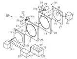
図1(a)は、非接触電力伝送装置10の構成を模式的に示す。図1(a)に示すように、非接触電力伝送装置10は、交流電源11と、交流電源11に接続された1次コイル12と、1次側共鳴コイル13と、2次側共鳴コイル14と、2次コイル15と、2次コイル15に接続された負荷16とを備えている。1次側共鳴コイル13及び2次側共鳴コイル14にはそれぞれコンデンサ17,18が並列に接続されている。1次コイル12、1次側共鳴コイル13、2次側共鳴コイル14、2次コイル15、負荷16及びコンデンサ17,18は共鳴系19を構成する。(First embodiment)
Hereinafter, a first embodiment of the present invention will be described with reference to FIGS.
FIG. 1A schematically shows the configuration of the non-contact
1次コイル12、1次側共鳴コイル13、2次側共鳴コイル14及び2次コイル15は同軸上に配置されるとともに、1次コイル12と1次側共鳴コイル13との軸方向の距離L1及び2次コイル15と2次側共鳴コイル14との軸方向の距離L2はそれぞれ変更可能に構成されている。また、非接触電力伝送装置10は、1次コイル12と1次側共鳴コイル13との軸方向の距離L1を変更する距離変更手段20と、2次コイル15と2次側共鳴コイル14との軸方向の距離L2を変更する距離変更手段21と、負荷16のインピーダンスを測定するインピーダンス測定手段22と、制御装置23とを備えている。インピーダンス測定手段22は共鳴系19の入力インピーダンス(1次コイル12の両端で測定した共鳴系19全体のインピーダンス)を測定する。制御装置23は、インピーダンス測定手段22の測定結果に基づいて、距離変更手段20,21を制御して前記軸方向の距離L1,L2を変更する。 The
交流電源11は、交流電圧を出力する電源である。交流電源11の交流電圧の周波数は、共鳴系19の予め設定された共鳴周波数に設定されている。この実施形態では、負荷16が50Ωの時に電力伝送効率が最大になる周波数に設定されている。 The AC power supply 11 is a power supply that outputs an AC voltage. The frequency of the AC voltage of the AC power supply 11 is set to a preset resonance frequency of the
1次コイル12、1次側共鳴コイル13、2次側共鳴コイル14及び2次コイル15は、それぞれ電線が一平面上で巻回された形状に形成されている。この実施形態では、1次コイル12及び2次コイル15が同じに形成され、1次側共鳴コイル13及び2次側共鳴コイル14が同じに形成されるとともに、1次コイル12及び2次コイル15の径が1次側共鳴コイル13及び2次側共鳴コイル14の径より小さく形成されている。図1(b)に1次コイル12と1次側共鳴コイル13との関係を示す。図1(b)に示すように、1次コイル12及び1次側共鳴コイル13は、巻きピッチPが一定の同じ渦巻きの一部を構成するとともに、両端が渦巻きの径方向に沿って配置されるように形成されている。そして、1次コイル12は両端において交流電源11に接続され、2次コイル15は両端において負荷16に接続されるようになっている。また、1次側共鳴コイル13及び2次側共鳴コイル14の両端にコンデンサ17,18がそれぞれ接続されている。 The
1次コイル12、1次側共鳴コイル13、2次側共鳴コイル14及び2次コイル15は、それぞれ、平板状又は平板枠状の支持部材24,25,26,27により同軸上に位置するように支持されている。1次側共鳴コイル13の支持部材25及び2次側共鳴コイル14の支持部材26は、それぞれ独立に図示しないガイド部材(例えば、ガイド軸)に沿って軸方向に移動可能に支持されている。距離変更手段20,21は、例えば、モータ28,29と、モータ28,29により回転されるねじ軸30a,31aと、ねじ軸30a,31aに螺合するナット部材30b,31bとにより構成されている。ナット部材30b,31bは支持部材25,26に固定され、モータ28,29の駆動により支持部材25,26と共に1次側共鳴コイル13や2次側共鳴コイル14が移動されるようになっている。 The
制御装置23は、CPU32及びメモリ33を備え、メモリ33にはインピーダンス測定手段22の測定結果、即ち共鳴系19の入力インピーダンスに基づいて、2次コイル15に接続されている負荷16のインピーダンスを演算する負荷演算プログラムが記憶されている。即ち、インピーダンス測定手段22は、負荷16のインピーダンスを間接的に測定している。また、メモリ33には負荷16のインピーダンスと、そのインピーダンスにおいて電力伝送効率(効率)が最大になるための1次コイル12と1次側共鳴コイル13との軸方向の距離L1及び2次コイル15と2次側共鳴コイル14との軸方向の距離L2との関係を示すデータがマップ又は関係式として記憶されている。このデータは予め試験により求められる。電力伝送効率ηは次のようにして求められる。 The
電力伝送効率η=(負荷での消費電力/1次コイルへの入力電力)×100[%]
また、CPU32は、インピーダンス測定手段22の測定結果から負荷16のインピーダンスを演算するとともに、その状態における適切な1次コイル12と1次側共鳴コイル13との軸方向の距離L1及び2次コイル15と2次側共鳴コイル14との軸方向の距離L2を設定する。そして、CPU32はその距離となるように距離変更手段20,21を制御する。Power transmission efficiency η = (power consumption at load / input power to primary coil) × 100 [%]
Further, the
図2は、非接触電力伝送装置10を移動体(例えば、車両)40に搭載された2次電池41に対して非接触充電を行うシステムに適用した場合の充電装置43と移動体40とを模式的に示す。2次側共鳴コイル14、2次コイル15、整流回路44、負荷16としての2次電池41、距離変更手段21及び距離変更手段21を制御する駆動制御装置42が移動体40に搭載されている。交流電源11、1次コイル12、1次側共鳴コイル13、距離変更手段20、インピーダンス測定手段22及び制御装置23は、2次電池41に非接触状態で充電を行う充電装置43に装備されている。充電装置43は充電ステーションに設けられている。駆動制御装置42は、制御装置23から図示しない無線通信装置を介して、適切な2次コイル15と2次側共鳴コイル14との軸方向の距離L2のデータを入力し、そのデータに基づいて距離変更手段21のモータ29を制御するようになっている。即ち、制御装置23のCPU32は駆動制御装置42を介して間接的に距離変更手段21を制御する。 FIG. 2 shows a charging
図3に、負荷16が50Ωで1次コイル12への入力電圧の周波数を10MHz程度とした場合に電力伝送効率ηが最大になる状態を基準として、1次側共鳴コイル13及び2次側共鳴コイル14間の距離を設定し、その状態から負荷16のインピーダンスを変更した場合における電力伝送効率が最大になる距離L1,L2の関係の一例を示す。なお、図3において、黒丸のグラフが距離L1,L2を調整した場合の電力伝送効率を示し、黒三角のグラフが距離L1,L2を0mmで一定に保持した場合(オフセット無しの場合)の電力伝送効率を示す。また、共鳴系19を構成する各コイルの電線として直径3mmの銅線を使用した。1次コイル12及び2次コイル15として半径r1(図1(b)に図示)が120mm程度、1次側共鳴コイル13及び2次側共鳴コイル14として半径r2(図1(b)に図示)が150mm程度のものを使用した。 FIG. 3 shows that the primary
次に前記のように構成された非接触電力伝送装置10の作用を説明する。
移動体40に搭載された2次電池41の充電が必要な状態になると、移動体40は充電装置43による2次電池41の充電を行うために、充電装置43と対応する位置で停止する。2次電池41への充電時には、充電装置43との距離が一定となる所定の充電位置に移動体40が停止した状態で充電が行われる。この停止位置は負荷16のインピーダンス即ち充電時の2次電池41の負荷のインピーダンスが50Ωのときに電力伝送効率が最大となるように設定されている。Next, the operation of the non-contact
When the secondary battery 41 mounted on the moving
移動体40が充電位置に停止すると、交流電源11から1次コイル12に予め設定された周波数で交流電圧が出力され、1次コイル12に磁場が発生する。この磁場が1次側共鳴コイル13と2次側共鳴コイル14とによる磁場共鳴により増強される。増強された2次側共鳴コイル14付近の磁場から2次コイル15により電力が取り出されて整流回路44を通して2次電池41に供給されて充電が行われる。 When the moving
充電前及び充電中、インピーダンス測定手段22が入力インピーダンスの測定を行い、測定結果は制御装置23に送られる。CPU32は測定結果に基づき、負荷のインピーダンスに対応した適切な距離L1,L2を演算する。そして、距離変更手段20,21に対して制御信号が送られ、距離変更手段20,21により1次コイル12と1次側共鳴コイル13との軸方向の距離L1及び2次コイル15と2次側共鳴コイル14との軸方向の距離L2が負荷のインピーダンスに対応した適切な距離に変更される。したがって、負荷が変動しても、電力伝送を適切な効率で行うことができる。 The impedance measuring means 22 measures the input impedance before and during charging, and the measurement result is sent to the
負荷の値が20Ω〜200Ωまで変化(変動)する場合、距離L1,L2を負荷のインピーダンスに関わりなく0mmに設定すると、図3に黒三角のグラフで示すように、負荷が40Ω〜76Ωの範囲では電力伝送効率が90%以上になったが、前記範囲から外れると電力伝送効率は90%未満になり、20Ωでは73%、200Ωでは61%になった。一方、距離L1,L2を負荷に対応して調整した場合は、黒丸のグラフで示すように、抵抗が20Ωの場合に電力伝送効率が90%で最小になり、32Ω〜140Ωの範囲で電力伝送効率が94%以上、抵抗が200Ωでも電力伝送効率が91%より大きくなった。 When the load value changes (varies) from 20Ω to 200Ω, if the distances L1 and L2 are set to 0 mm regardless of the load impedance, the load ranges from 40Ω to 76Ω as shown by the black triangle graph in FIG. The power transmission efficiency was 90% or more, but when it was out of the range, the power transmission efficiency became less than 90%, 73% at 20Ω and 61% at 200Ω. On the other hand, when the distances L1 and L2 are adjusted according to the load, as shown by the black circle graph, when the resistance is 20Ω, the power transmission efficiency is 90% and the power transmission is in the range of 32Ω to 140Ω. Even when the efficiency was 94% or more and the resistance was 200Ω, the power transmission efficiency was greater than 91%.
この実施形態によれば、以下に示す効果を得ることができる。
(1)非接触電力伝送装置10は、交流電源11と、交流電源11に接続された1次コイル12と、1次側共鳴コイル13と、2次側共鳴コイル14と、2次コイル15と、2次コイル15に接続された負荷16とを備え、1次コイル12、1次側共鳴コイル13、2次側共鳴コイル14、2次コイル15及び負荷16は共鳴系19を構成する。1次コイル12と1次側共鳴コイル13との軸方向の距離L1及び2次コイル15と2次側共鳴コイル14との軸方向の距離L2の少なくとも一方が、負荷16のインピーダンスにおいて電力伝送効率が最大となる値に調整される。したがって、負荷16のインピーダンスが変化しても、交流電源11の交流電圧の周波数を変更せずに、電力伝送を適切な効率で行うことができる。According to this embodiment, the following effects can be obtained.
(1) The non-contact
(2)負荷16のインピーダンスを間接的に測定するインピーダンス測定手段22と、1次コイル12と1次側共鳴コイル13との軸方向の距離L1を変更する距離変更手段20と、2次コイル15と2次側共鳴コイル14との軸方向の距離L2を変更する距離変更手段21とを備えている。制御装置23は、インピーダンス測定手段22の測定結果に基づいて、負荷16のインピーダンスに対応した適切な距離L1,L2を演算する。そして、交流電源11からの電力伝送中に2次コイル15に接続されている負荷16のインピーダンスが変動すると、負荷16のインピーダンスに対応して前記軸方向の距離L1,L2が距離変更手段20,21により自動的に変更される。したがって、負荷16のインピーダンスが変動しても、交流電源11の交流電圧の周波数を変更せずに、電力伝送を適切な効率で行うことができる。 (2) Impedance measuring means 22 for indirectly measuring the impedance of the
(3)距離変更手段20,21は1次側共鳴コイル13及び2次側共鳴コイル14の少なくとも一方を移動させて軸方向の距離L1,L2を変更する。したがって、交流電源11に接続されている1次コイル12や負荷16に接続されている2次コイル15を移動させる構成に比べて、軸方向の距離L1,L2を変更するための構成が簡単になる。 (3) The distance changing means 20 and 21 change the axial distances L1 and L2 by moving at least one of the
(4)非接触電力伝送装置10は、移動体40に搭載された2次電池41に対して非接触充電を行うシステムに適用されている。そして、負荷16のインピーダンスを計測するインピーダンス測定手段22が移動体40ではなく充電装置43に設けられている。したがって、インピーダンス測定手段22を移動体40側に設ける構成に比べてインピーダンス測定手段22の数を少なくすることができる。 (4) The non-contact
(5)2次側共鳴コイル14及び2次コイル15は移動体40に搭載されるとともに2次コイル15は負荷としての2次電池41に接続されており、交流電源11、1次コイル12及び1次側共鳴コイル13は2次電池41に非接触状態で充電を行う充電装置43に装備されている。そして、充電装置43は制御装置23により、2次電池41の充電状態を把握して充電制御を行う。したがって、充電に際して充電不足や過充電を回避することができる。 (5) The secondary
(6)CPU32は、インピーダンス測定手段22の測定結果に基づいて、2次コイル15に接続されている2次電池41(負荷16)のインピーダンスを演算する。したがって、2次電池41の充電状態を把握するのに専用のセンサを設ける必要がない。また、送電側で受電側の負荷のインピーダンスを計測することができる。 (6) The
(第2の実施形態)
次に第2の実施形態を説明する。この実施形態では、非接触電力伝送装置10の送電側だけでなく、受電側を構成する要素も移動体40に装備されずに定位置に配置される点と、負荷16として定負荷でかつ負荷のインピーダンスが異なるものが2次コイル15に対して、目的に応じて適宜接続されて使用される点が前記第1の実施形態と異なっている。第1の実施形態と基本的に同一部分は同一符号を付して詳しい説明を省略する。(Second Embodiment)
Next, a second embodiment will be described. In this embodiment, not only the power transmission side of the non-contact
図4に示すように、2次コイル15には、負荷16としての電気機器がコネクタ34を介して接続可能に構成されている。メモリ33には、2次コイル15に負荷16が接続されると、インピーダンス測定手段22により負荷16のインピーダンスを測定するとともに、その測定結果に基づいて適切な効率で電力伝送を行うための適切な距離L1,L2をCPU32が演算するプログラムが記憶されている。 As shown in FIG. 4, an electrical device as a
この実施形態では、2次コイル15に負荷16が接続されると、電力伝送を適切な効率で行うための1次コイル12と1次側共鳴コイル13との軸方向の距離L1及び2次コイル15と2次側共鳴コイル14との軸方向の距離L2が演算され、距離変更手段20,21により1次及び2次側共鳴コイル13,14が適切な位置に移動される。そして、交流電源11から一定の周波数で交流電圧が出力されて電力伝送が行われる。 In this embodiment, when a
この第2の実施形態によれば、第1の実施形態の(1),(3)の効果に加えて以下の効果を得ることができる。
(7)負荷16として定負荷でインピーダンスが異なるものが使用されるとともに、2次コイル15に負荷16が接続されると、接続された負荷16のインピーダンスに対応して距離変更手段20,21により軸方向の距離L1,L2の少なくとも一方が電力伝送を適切な効率で行う値に調整される。したがって、異なるインピーダンスの負荷16が使用されても、交流電源11の交流電圧の周波数を変更せずに、電力伝送中に負荷16のインピーダンスを測定せずに電力伝送を適切な効率で行うことができる。According to the second embodiment, the following effects can be obtained in addition to the effects (1) and (3) of the first embodiment.
(7) When the
実施形態は前記に限定されるものではなく、例えば、次のように具体化してもよい。
○ 1次コイル12及び2次コイル15の径が1次側共鳴コイル13及び2次側共鳴コイル14の径より小さく形成されている構成に限らない。例えば、1次コイル12の径が1次側共鳴コイル13の径より小さく、2次コイル15の径が2次側共鳴コイル14の径より大きく形成したり、1次コイル12の径が1次側共鳴コイル13径より大きく、2次コイル15の径が2次側共鳴コイル14の径より小さく形成したりしてもよい。また、1次コイル12及び2次コイル15の径が1次側共鳴コイル13及び2次側共鳴コイル14の径より大きく形成したり、1次コイル12及び2次コイル15の径が1次側共鳴コイル13及び2次側共鳴コイル14の径と同じに形成したりしてもよい。The embodiment is not limited to the above, and may be embodied as follows, for example.
O The diameter of the
1次コイル12の径が1次側共鳴コイル13の径より小さく、2次コイル15の径が2次側共鳴コイル14の径より大きな場合の1次コイル12及び2次コイル15と1次側共鳴コイル13及び2次側共鳴コイル14間の距離と、負荷と、電力伝送効率との関係を図5に示す。また、1次コイル12の径が1次側共鳴コイル13の径より大きく、2次コイル15の径が2次側共鳴コイル14の径より小さな場合における同じ関係を図6に、1次コイル12及び2次コイル15の径が1次側共鳴コイル13及び2次側共鳴コイル14の径より大きな場合における同じ関係を図7にそれぞれ示す。なお、図5〜図7において、黒丸のグラフは距離L1,L2を調整した場合の電力伝送効率を示し、黒三角のグラフは距離L1,L2を0mmで一定に保持した場合(オフセット無しの場合)の電力伝送効率を示す。 The
図3及び図5に示すように、1次コイル12の径が1次側共鳴コイル13の径より小さい場合は、電力伝送効率が最大となる1次コイル12と1次側共鳴コイル13との軸方向の距離L1は負荷の増加によってほぼ単調増加する。しかし、図6及び図7に示すように、1次コイル12の径が1次側共鳴コイル13の径より大きい場合は、電力伝送効率が最大となる1次コイル12と1次側共鳴コイル13との軸方向の距離L1は単調増加ではなく、ピークを有する特性になる。一方、2次コイル15の場合は、2次コイル15の径が2次側共鳴コイル14の径より大きくても小さくても、電力伝送効率が最大となる2次コイル15と2次側共鳴コイル14との軸方向の距離L2は負荷の増加によってほぼ単調減少する。また、負荷が少なくとも80Ωより大きい場合は、1次コイル12と2次コイル15との大小関係に関わらず、距離L1の方が距離L2より大きくなる。 As shown in FIGS. 3 and 5, when the diameter of the
また、1次コイル12の径が1次側共鳴コイル13の径より小さい場合の方が、1次コイル12の径が1次側共鳴コイル13の径より大きい場合に比べて、負荷のインピーダンスの広い範囲にわたって電力伝送効率を90%より高い状態に維持することができる。 Further, when the diameter of the
○ 1次コイル12と1次側共鳴コイル13との軸方向の距離L1及び2次コイル15と2次側共鳴コイル14との軸方向の距離L2の距離は、負荷16のインピーダンスに対応して電力伝送効率が最大となる距離に限らず、電力伝送効率が適切な値になる距離となるように距離変更手段20,21によって調整されればよい。「電力伝送効率が適切な値」とは、電力伝送効率がその負荷のインピーダンスでの最大値の90%以上であることを意味する。 The axial distance L1 between the
○ 1次コイル12と1次側共鳴コイル13との軸方向の距離L1及び2次コイル15と2次側共鳴コイル14との軸方向の距離L2の距離を変更する場合、1次側共鳴コイル13及び2次側共鳴コイル14の位置を変えずに、距離変更手段20,21が1次コイル12及び2次コイル15の位置を変更する構成としてもよい。 When changing the axial distance L1 between the
○ 2次電池41を備えた移動体40に充電を行うシステムに適用する場合、移動体40は車両や無人搬送車に限らず、2次電池41を備えた自走式のロボットあるいは携帯用の電子機器であってもよい。また、携帯用の電子機器の場合、小型化を図るため2次コイル15と2次側共鳴コイル14との軸方向の距離L2を変更せずに、1次コイル12と1次側共鳴コイル13との軸方向の距離L1のみを変更する構成としてもよい。例えば、負荷16の変動範囲が80Ω〜200Ωの場合、1次コイル12及び2次コイル15の径を1次側共鳴コイル13及び2次側共鳴コイル14の径より小さく形成すれば、距離変更手段21を設けなくても、図3に示すように、負荷16が変動しても電力伝送効率を92%以上に確保することができる。 ○ When applied to a system for charging a
○ 非接触電力伝送装置10は、動力源としては非接触電力伝送を受けずに通常の電力で駆動されるコンベア等の移送手段により定められた作業位置に移動され、かつ定電力で駆動されるとともに定格電力が異なる複数のモータを負荷16として備えた装置に適用してもよい。この場合、各モータが負荷16を構成し、移送手段には各負荷16に対応して2次側共鳴コイル14、2次コイル15及び距離変更手段21が設けられる。また、作業位置に交流電源11、1次コイル12、1次側共鳴コイル13、距離変更手段20及び制御装置23が設けられる。そして、負荷16が作業位置に移動された状態で、距離L1,L2がその負荷16に対応した値に調整された後、交流電源11から電力伝送が行われる。 The non-contact
○ 1次コイル12、1次側共鳴コイル13、2次側共鳴コイル14及び2次コイル15を同軸上に配置する構成として、各コイルが水平方向に延びる軸上に位置する構成に代えて、例えば、各コイルが鉛直方向に延びる軸上に位置する構成にしてもよい。非接触電力伝送装置10の2次側(受電側)が移動体40に装備される場合、1次側(送電側)は移動体40の停止位置の上方(例えば天井)に設けられたり、停止位置の下方(例えば床又は地上側の凹部)に設けられたりする。 As a configuration in which the
○ インピーダンス測定手段22として共鳴系19における入力インピーダンスを測定して間接的に負荷16のインピーダンスを測定する構成に代えて、負荷16のインピーダンスを直接測定する構成のインピーダンス測定手段22を設けてもよい。この場合、インピーダンス測定手段22は受電側(2次側)に設けられ、2次側が移動体40に装備される非接触電力伝送装置10に適用する場合は、インピーダンス測定手段22の測定結果は無線装置により制御装置23に送られる。 As an impedance measuring means 22, an impedance measuring means 22 configured to directly measure the impedance of the
○ 非接触電力伝送装置10が使用中に段階的に負荷のインピーダンスが変化する電気機器を負荷16として使用する場合、負荷のインピーダンスが変化する時期が予め決まっている場合、負荷16の駆動開始時(非接触電力伝送装置10の電力伝送開始時)からの経過時間で、距離L1,L2を調整するようにしてもよい。 ○ When an electric device whose load impedance changes stepwise while the non-contact
○ 1次コイル12、1次側共鳴コイル13、2次側共鳴コイル14及び2次コイル15の規格の巻数、巻径は前記実施形態の値に限らず、伝送しようとする電力の大きさ等に対応して適宜設定される。 The standard number of turns and the diameter of the
○ 1次コイル12、1次側共鳴コイル13、2次側共鳴コイル14及び2次コイル15は、それぞれ電線が一平面上で渦巻き状に巻回された形状に限らず、電線がコイルスプリングのように筒状に巻回された形状としてもよい。 The
○ 1次コイル12、1次側共鳴コイル13、2次側共鳴コイル14及び2次コイル15の外形は、円形に限らず、例えば、四角形や六角形や三角形等の多角形にしたり、あるいは楕円形にしたりしてもよい。 The outer shape of the
○ 1次コイル12、1次側共鳴コイル13、2次側共鳴コイル14及び2次コイル15の外形は、ほぼ左右対称な形状に限らず、非対称な形状であってもよい。
○ 1次側共鳴コイル13及び2次側共鳴コイル14に接続されたコンデンサ17,18を省略してもよい。しかし、コンデンサ17,18を接続した構成の方が、コンデンサ17,18を省略した場合に比べて、共鳴周波数を下げることができる。また、共鳴周波数が同じであれば、コンデンサ17,18を省略した場合に比べて、1次側共鳴コイル13及び2次側共鳴コイル14の小型化が可能になる。The outer shape of the
The
○ 交流電源11は、交流電圧の周波数が変更可能でも変更不能でもよい。
○ 電線は断面円形の一般的な銅線に限らず、矩形断面の板状の銅線であってもよい。
○ 電線の材料は銅に限らず、例えば、アルミニウムや銀を用いてもよい。The AC power supply 11 may be capable of changing or not changing the frequency of the AC voltage.
The electric wire is not limited to a general copper wire having a circular cross section, and may be a plate-like copper wire having a rectangular cross section.
○ The material of the electric wire is not limited to copper, and for example, aluminum or silver may be used.
以下の技術的思想(発明)は前記実施形態から把握できる。
(1)請求項1又は請求項2に記載の発明において、前記2次側共鳴コイル及び前記2次コイルは移動体に搭載されるとともに前記2次コイルは負荷としての2次電池に接続されており、前記交流電源、前記1次コイル及び前記1次側共鳴コイルは前記2次電池に非接触状態で充電を行う充電装置に装備されている。The following technical idea (invention) can be understood from the embodiment.
(1) In the invention according to
(2)請求項1〜請求項4及び前記技術的思想(1)のいずれか1項に記載の発明において、前記1次コイルの径は前記1次側共鳴コイルの径より大きく形成されている。 (2) In the invention according to any one of
L1,L2…距離、10…非接触電力伝送装置、11…交流電源、12…1次コイル、13…1次側共鳴コイル、14…2次側共鳴コイル、15…2次コイル、16…負荷、19…共鳴系、20,21…距離変更手段、22…インピーダンス測定手段、41…負荷としての2次電池。 L1, L2 ... Distance, 10 ... Non-contact power transmission device, 11 ... AC power supply, 12 ... Primary coil, 13 ... Primary resonance coil, 14 ... Secondary resonance coil, 15 ... Secondary coil, 16 ... Load , 19 ... resonance system, 20, 21 ... distance changing means, 22 ... impedance measuring means, 41 ... secondary battery as a load.
Claims (4)
Translated fromJapanese前記交流電源に接続された1次コイルと、
1次側共鳴コイルと、
2次側共鳴コイルと、
2次コイルと、
前記2次コイルに接続された負荷とを備え、
前記1次コイル、前記1次側共鳴コイル、前記2次側共鳴コイル、前記2次コイル及び前記負荷は共鳴系を構成する非接触電力伝送装置であって、
前記1次コイルと前記1次側共鳴コイルとの軸方向の距離及び前記2次コイルと前記2次側共鳴コイルとの軸方向の距離の少なくとも一方が、前記負荷のインピーダンスに対応して予め設定された距離となるように調整されて電力伝送効率が適切な値に維持されることを特徴とする非接触電力伝送装置。AC power supply,
A primary coil connected to the AC power source;
A primary resonance coil;
A secondary resonance coil;
A secondary coil;
A load connected to the secondary coil,
The primary coil, the primary resonance coil, the secondary resonance coil, the secondary coil, and the load are non-contact power transmission devices constituting a resonance system,
At least one of the axial distance between the primary coil and the primary resonance coil and the axial distance between the secondary coil and the secondary resonance coil is set in advance corresponding to the impedance of the load. The non-contact power transmission apparatus is characterized in that the power transmission efficiency is maintained at an appropriate value by being adjusted so as to be a predetermined distance.
Priority Applications (4)
| Application Number | Priority Date | Filing Date | Title |
|---|---|---|---|
| JP2009027670AJP5262785B2 (en) | 2009-02-09 | 2009-02-09 | Non-contact power transmission device |
| KR1020100010754AKR101108925B1 (en) | 2009-02-09 | 2010-02-05 | Contactless power transmitter |
| US12/702,112US8432125B2 (en) | 2009-02-09 | 2010-02-08 | Non-contact power transmission apparatus |
| EP10152920AEP2216878A2 (en) | 2009-02-09 | 2010-02-08 | Non-contact power transmission apparatus |
Applications Claiming Priority (1)
| Application Number | Priority Date | Filing Date | Title |
|---|---|---|---|
| JP2009027670AJP5262785B2 (en) | 2009-02-09 | 2009-02-09 | Non-contact power transmission device |
Publications (2)
| Publication Number | Publication Date |
|---|---|
| JP2010183811A JP2010183811A (en) | 2010-08-19 |
| JP5262785B2true JP5262785B2 (en) | 2013-08-14 |
Family
ID=42224664
Family Applications (1)
| Application Number | Title | Priority Date | Filing Date |
|---|---|---|---|
| JP2009027670AExpired - Fee RelatedJP5262785B2 (en) | 2009-02-09 | 2009-02-09 | Non-contact power transmission device |
Country Status (4)
| Country | Link |
|---|---|
| US (1) | US8432125B2 (en) |
| EP (1) | EP2216878A2 (en) |
| JP (1) | JP5262785B2 (en) |
| KR (1) | KR101108925B1 (en) |
Families Citing this family (146)
| Publication number | Priority date | Publication date | Assignee | Title |
|---|---|---|---|---|
| US7825543B2 (en) | 2005-07-12 | 2010-11-02 | Massachusetts Institute Of Technology | Wireless energy transfer |
| US9421388B2 (en) | 2007-06-01 | 2016-08-23 | Witricity Corporation | Power generation for implantable devices |
| US8115448B2 (en) | 2007-06-01 | 2012-02-14 | Michael Sasha John | Systems and methods for wireless power |
| CN102099958B (en) | 2008-05-14 | 2013-12-25 | 麻省理工学院 | Wireless power transfer including interference enhancement |
| US9473209B2 (en)* | 2008-08-20 | 2016-10-18 | Intel Corporation | Wireless power transfer apparatus and method thereof |
| US8933594B2 (en) | 2008-09-27 | 2015-01-13 | Witricity Corporation | Wireless energy transfer for vehicles |
| US8304935B2 (en) | 2008-09-27 | 2012-11-06 | Witricity Corporation | Wireless energy transfer using field shaping to reduce loss |
| US8587153B2 (en) | 2008-09-27 | 2013-11-19 | Witricity Corporation | Wireless energy transfer using high Q resonators for lighting applications |
| US8461720B2 (en) | 2008-09-27 | 2013-06-11 | Witricity Corporation | Wireless energy transfer using conducting surfaces to shape fields and reduce loss |
| US8686598B2 (en) | 2008-09-27 | 2014-04-01 | Witricity Corporation | Wireless energy transfer for supplying power and heat to a device |
| US8669676B2 (en) | 2008-09-27 | 2014-03-11 | Witricity Corporation | Wireless energy transfer across variable distances using field shaping with magnetic materials to improve the coupling factor |
| US9544683B2 (en) | 2008-09-27 | 2017-01-10 | Witricity Corporation | Wirelessly powered audio devices |
| US8569914B2 (en) | 2008-09-27 | 2013-10-29 | Witricity Corporation | Wireless energy transfer using object positioning for improved k |
| US8957549B2 (en) | 2008-09-27 | 2015-02-17 | Witricity Corporation | Tunable wireless energy transfer for in-vehicle applications |
| US9744858B2 (en) | 2008-09-27 | 2017-08-29 | Witricity Corporation | System for wireless energy distribution in a vehicle |
| US8552592B2 (en) | 2008-09-27 | 2013-10-08 | Witricity Corporation | Wireless energy transfer with feedback control for lighting applications |
| US9184595B2 (en) | 2008-09-27 | 2015-11-10 | Witricity Corporation | Wireless energy transfer in lossy environments |
| US9105959B2 (en) | 2008-09-27 | 2015-08-11 | Witricity Corporation | Resonator enclosure |
| US8643326B2 (en) | 2008-09-27 | 2014-02-04 | Witricity Corporation | Tunable wireless energy transfer systems |
| US8324759B2 (en) | 2008-09-27 | 2012-12-04 | Witricity Corporation | Wireless energy transfer using magnetic materials to shape field and reduce loss |
| US8497601B2 (en) | 2008-09-27 | 2013-07-30 | Witricity Corporation | Wireless energy transfer converters |
| US9577436B2 (en) | 2008-09-27 | 2017-02-21 | Witricity Corporation | Wireless energy transfer for implantable devices |
| US8410636B2 (en) | 2008-09-27 | 2013-04-02 | Witricity Corporation | Low AC resistance conductor designs |
| US8400017B2 (en) | 2008-09-27 | 2013-03-19 | Witricity Corporation | Wireless energy transfer for computer peripheral applications |
| US8907531B2 (en) | 2008-09-27 | 2014-12-09 | Witricity Corporation | Wireless energy transfer with variable size resonators for medical applications |
| US9601261B2 (en) | 2008-09-27 | 2017-03-21 | Witricity Corporation | Wireless energy transfer using repeater resonators |
| US8487480B1 (en) | 2008-09-27 | 2013-07-16 | Witricity Corporation | Wireless energy transfer resonator kit |
| US8901779B2 (en) | 2008-09-27 | 2014-12-02 | Witricity Corporation | Wireless energy transfer with resonator arrays for medical applications |
| US8947186B2 (en) | 2008-09-27 | 2015-02-03 | Witricity Corporation | Wireless energy transfer resonator thermal management |
| US8772973B2 (en) | 2008-09-27 | 2014-07-08 | Witricity Corporation | Integrated resonator-shield structures |
| US8476788B2 (en) | 2008-09-27 | 2013-07-02 | Witricity Corporation | Wireless energy transfer with high-Q resonators using field shaping to improve K |
| US9601270B2 (en) | 2008-09-27 | 2017-03-21 | Witricity Corporation | Low AC resistance conductor designs |
| US9396867B2 (en) | 2008-09-27 | 2016-07-19 | Witricity Corporation | Integrated resonator-shield structures |
| US8963488B2 (en) | 2008-09-27 | 2015-02-24 | Witricity Corporation | Position insensitive wireless charging |
| US9065423B2 (en) | 2008-09-27 | 2015-06-23 | Witricity Corporation | Wireless energy distribution system |
| US8937408B2 (en) | 2008-09-27 | 2015-01-20 | Witricity Corporation | Wireless energy transfer for medical applications |
| US9035499B2 (en) | 2008-09-27 | 2015-05-19 | Witricity Corporation | Wireless energy transfer for photovoltaic panels |
| US8629578B2 (en) | 2008-09-27 | 2014-01-14 | Witricity Corporation | Wireless energy transfer systems |
| US8461722B2 (en) | 2008-09-27 | 2013-06-11 | Witricity Corporation | Wireless energy transfer using conducting surfaces to shape field and improve K |
| US9515494B2 (en) | 2008-09-27 | 2016-12-06 | Witricity Corporation | Wireless power system including impedance matching network |
| US8723366B2 (en) | 2008-09-27 | 2014-05-13 | Witricity Corporation | Wireless energy transfer resonator enclosures |
| US8692412B2 (en) | 2008-09-27 | 2014-04-08 | Witricity Corporation | Temperature compensation in a wireless transfer system |
| US9601266B2 (en) | 2008-09-27 | 2017-03-21 | Witricity Corporation | Multiple connected resonators with a single electronic circuit |
| US8922066B2 (en) | 2008-09-27 | 2014-12-30 | Witricity Corporation | Wireless energy transfer with multi resonator arrays for vehicle applications |
| US9106203B2 (en) | 2008-09-27 | 2015-08-11 | Witricity Corporation | Secure wireless energy transfer in medical applications |
| US8901778B2 (en) | 2008-09-27 | 2014-12-02 | Witricity Corporation | Wireless energy transfer with variable size resonators for implanted medical devices |
| US8928276B2 (en) | 2008-09-27 | 2015-01-06 | Witricity Corporation | Integrated repeaters for cell phone applications |
| US8466583B2 (en) | 2008-09-27 | 2013-06-18 | Witricity Corporation | Tunable wireless energy transfer for outdoor lighting applications |
| EP3179640A1 (en) | 2008-09-27 | 2017-06-14 | WiTricity Corporation | Wireless energy transfer systems |
| US8692410B2 (en) | 2008-09-27 | 2014-04-08 | Witricity Corporation | Wireless energy transfer with frequency hopping |
| US9246336B2 (en) | 2008-09-27 | 2016-01-26 | Witricity Corporation | Resonator optimizations for wireless energy transfer |
| US9318922B2 (en) | 2008-09-27 | 2016-04-19 | Witricity Corporation | Mechanically removable wireless power vehicle seat assembly |
| US8598743B2 (en) | 2008-09-27 | 2013-12-03 | Witricity Corporation | Resonator arrays for wireless energy transfer |
| US8471410B2 (en) | 2008-09-27 | 2013-06-25 | Witricity Corporation | Wireless energy transfer over distance using field shaping to improve the coupling factor |
| US8912687B2 (en) | 2008-09-27 | 2014-12-16 | Witricity Corporation | Secure wireless energy transfer for vehicle applications |
| US9160203B2 (en) | 2008-09-27 | 2015-10-13 | Witricity Corporation | Wireless powered television |
| US8587155B2 (en) | 2008-09-27 | 2013-11-19 | Witricity Corporation | Wireless energy transfer using repeater resonators |
| US8441154B2 (en) | 2008-09-27 | 2013-05-14 | Witricity Corporation | Multi-resonator wireless energy transfer for exterior lighting |
| US8461721B2 (en) | 2008-09-27 | 2013-06-11 | Witricity Corporation | Wireless energy transfer using object positioning for low loss |
| US8946938B2 (en) | 2008-09-27 | 2015-02-03 | Witricity Corporation | Safety systems for wireless energy transfer in vehicle applications |
| US8482158B2 (en) | 2008-09-27 | 2013-07-09 | Witricity Corporation | Wireless energy transfer using variable size resonators and system monitoring |
| US9093853B2 (en) | 2008-09-27 | 2015-07-28 | Witricity Corporation | Flexible resonator attachment |
| US8362651B2 (en) | 2008-10-01 | 2013-01-29 | Massachusetts Institute Of Technology | Efficient near-field wireless energy transfer using adiabatic system variations |
| JP5353376B2 (en)* | 2009-03-31 | 2013-11-27 | 富士通株式会社 | Wireless power device and wireless power receiving method |
| JP4915438B2 (en)* | 2009-07-24 | 2012-04-11 | Tdk株式会社 | Wireless power supply apparatus and wireless power transmission system |
| US8674550B2 (en)* | 2010-03-25 | 2014-03-18 | General Electric Company | Contactless power transfer system and method |
| US8841881B2 (en) | 2010-06-02 | 2014-09-23 | Bryan Marc Failing | Energy transfer with vehicles |
| WO2012014484A2 (en)* | 2010-07-29 | 2012-02-02 | Kabushiki Kaisha Toyota Jidoshokki | Resonance type non-contact power supply system |
| KR101441453B1 (en)* | 2010-08-25 | 2014-09-18 | 한국전자통신연구원 | Apparatus and method for reducing electric field and radiation field in magnetic resonant coupling coils or magnetic induction device for wireless energy transfer |
| US9602168B2 (en) | 2010-08-31 | 2017-03-21 | Witricity Corporation | Communication in wireless energy transfer systems |
| WO2012044103A2 (en) | 2010-09-30 | 2012-04-05 | Lg Innotek Co., Ltd. | Energy transmission apparatus and method |
| WO2012058466A1 (en) | 2010-10-29 | 2012-05-03 | Qualcomm Incorporated | Wireless energy transfer via coupled parasitic resonators |
| KR101842180B1 (en)* | 2010-12-24 | 2018-03-26 | 가부시키가이샤 한도오따이 에네루기 켄큐쇼 | Power feeding device and contactless power feeding system provided with power feeding device |
| CN103443883B (en)* | 2011-01-14 | 2016-10-12 | 香港城市大学 | Apparatus and method for wireless power transfer |
| JP2012165527A (en) | 2011-02-04 | 2012-08-30 | Nitto Denko Corp | Wireless power supply system |
| US10685780B2 (en)* | 2011-03-29 | 2020-06-16 | Sony Corporation | Electric power feed apparatus, electric power feed system, and electronic apparatus |
| KR102017106B1 (en)* | 2011-05-17 | 2019-10-21 | 삼성전자주식회사 | Power transmitting device and method of transmitting power for communicating with one or more power receiving devices |
| US9735623B2 (en) | 2011-05-17 | 2017-08-15 | Samsung Electronics Co., Ltd. | Power transmitting method and power transmitter for communication with power receiver |
| US9244500B2 (en)* | 2011-05-23 | 2016-01-26 | Intel Corporation | System integration supporting completely wireless peripheral applications |
| US8552595B2 (en)* | 2011-05-31 | 2013-10-08 | General Electric Company | System and method for contactless power transfer in portable image detectors |
| US9000620B2 (en) | 2011-05-31 | 2015-04-07 | Samsung Electronics Co., Ltd. | Apparatus and method of dividing wireless power in wireless resonant power transmission system |
| JP5071574B1 (en)* | 2011-07-05 | 2012-11-14 | ソニー株式会社 | Sensing device, power receiving device, non-contact power transmission system, and sensing method |
| US9948145B2 (en) | 2011-07-08 | 2018-04-17 | Witricity Corporation | Wireless power transfer for a seat-vest-helmet system |
| CN108110907B (en) | 2011-08-04 | 2022-08-02 | 韦特里西提公司 | Tunable wireless power supply architecture |
| EP2754222B1 (en) | 2011-09-09 | 2015-11-18 | Witricity Corporation | Foreign object detection in wireless energy transfer systems |
| US20130062966A1 (en) | 2011-09-12 | 2013-03-14 | Witricity Corporation | Reconfigurable control architectures and algorithms for electric vehicle wireless energy transfer systems |
| JP5665710B2 (en)* | 2011-09-26 | 2015-02-04 | 株式会社東芝 | Wireless power transmission system, power transmission device and power reception device |
| US9721721B2 (en) | 2011-09-29 | 2017-08-01 | Lg Innotek Co., Ltd. | Wireless power transmitter, wireless power receiver and impedence control method |
| EP2768116A4 (en)* | 2011-10-12 | 2015-09-02 | Toyota Motor Co Ltd | POWER TRANSMISSION APPARATUS AND SYSTEM AND POWER RECEPTION APPARATUS |
| US9318257B2 (en) | 2011-10-18 | 2016-04-19 | Witricity Corporation | Wireless energy transfer for packaging |
| CA2853824A1 (en) | 2011-11-04 | 2013-05-10 | Witricity Corporation | Wireless energy transfer modeling tool |
| JP2013102593A (en)* | 2011-11-08 | 2013-05-23 | Sony Corp | Magnetic coupling unit and magnetic coupling system |
| KR101318742B1 (en)* | 2011-11-08 | 2013-10-16 | 삼성전자주식회사 | Wireless power transmission system and design method of wireless power transmission system considering impedence matching condition |
| JP6126013B2 (en)* | 2011-11-25 | 2017-05-10 | トヨタ自動車株式会社 | vehicle |
| KR101241659B1 (en) | 2011-12-19 | 2013-03-11 | 엘지이노텍 주식회사 | Apparatus for transmitting wireless power and method for transmitting wireless power |
| KR101338654B1 (en)* | 2011-12-19 | 2013-12-06 | 엘지이노텍 주식회사 | Apparatus for transmitting wireless power, apparatus for receiving wireless power, system for transmitting wireless power and method for transmitting wireless power |
| JP2015508987A (en) | 2012-01-26 | 2015-03-23 | ワイトリシティ コーポレーションWitricity Corporation | Wireless energy transmission with reduced field |
| TWI587597B (en) | 2012-02-17 | 2017-06-11 | Lg伊諾特股份有限公司 | Wireless power transmitter, wireless power receiver, and power transmission method of wireless power transmitting system |
| KR101988009B1 (en) | 2012-03-23 | 2019-06-11 | 삼성전자주식회사 | Wireless power transmission system and method that controls resonance frequency and increases coupling efficiency |
| WO2013145143A1 (en)* | 2012-03-28 | 2013-10-03 | 富士通株式会社 | Power transmitting apparatus |
| US9343922B2 (en) | 2012-06-27 | 2016-05-17 | Witricity Corporation | Wireless energy transfer for rechargeable batteries |
| US9287607B2 (en) | 2012-07-31 | 2016-03-15 | Witricity Corporation | Resonator fine tuning |
| US9595378B2 (en) | 2012-09-19 | 2017-03-14 | Witricity Corporation | Resonator enclosure |
| EP2909912B1 (en) | 2012-10-19 | 2022-08-10 | WiTricity Corporation | Foreign object detection in wireless energy transfer systems |
| US9842684B2 (en) | 2012-11-16 | 2017-12-12 | Witricity Corporation | Systems and methods for wireless power system with improved performance and/or ease of use |
| KR101985022B1 (en)* | 2012-12-06 | 2019-05-31 | 엘에스전선 주식회사 | Wireless Power Relay Apparatus and Wireless Power Transmission System |
| US9435830B2 (en)* | 2013-01-18 | 2016-09-06 | Cyberonics, Inc. | Implantable medical device depth estimation |
| JP2014168359A (en)* | 2013-02-28 | 2014-09-11 | Nitto Denko Corp | Wireless power transmission device, power supply control method of wireless power transmission device, and method of manufacturing wireless power transmission device |
| CN103280898B (en)* | 2013-05-27 | 2015-10-21 | 清华大学 | Magnet coupled resonant type wireless power transfer |
| JP6376732B2 (en)* | 2013-07-18 | 2018-08-22 | Ihi運搬機械株式会社 | Contactless power supply system |
| US9857821B2 (en) | 2013-08-14 | 2018-01-02 | Witricity Corporation | Wireless power transfer frequency adjustment |
| WO2015040649A1 (en)* | 2013-09-17 | 2015-03-26 | パナソニックIpマネジメント株式会社 | Wireless power transmission device |
| US10038340B2 (en) | 2013-10-21 | 2018-07-31 | Electronics And Telecommunications Research Institute | Wireless power transmission method and apparatus for improving spectrum efficiency and space efficiency based on impedance matching and relay resonance |
| WO2015107528A1 (en)* | 2014-01-19 | 2015-07-23 | Powermat Technologies Ltd. | Wireless power outlet and method of transferring power thereby |
| KR101943082B1 (en)* | 2014-01-23 | 2019-04-18 | 한국전자통신연구원 | Wireless power transmission device, wireless power receiving device and wireless power transmission system |
| US9780573B2 (en) | 2014-02-03 | 2017-10-03 | Witricity Corporation | Wirelessly charged battery system |
| US9952266B2 (en) | 2014-02-14 | 2018-04-24 | Witricity Corporation | Object detection for wireless energy transfer systems |
| US9892849B2 (en) | 2014-04-17 | 2018-02-13 | Witricity Corporation | Wireless power transfer systems with shield openings |
| US9842687B2 (en) | 2014-04-17 | 2017-12-12 | Witricity Corporation | Wireless power transfer systems with shaped magnetic components |
| US9837860B2 (en) | 2014-05-05 | 2017-12-05 | Witricity Corporation | Wireless power transmission systems for elevators |
| JP2017518018A (en) | 2014-05-07 | 2017-06-29 | ワイトリシティ コーポレーションWitricity Corporation | Foreign object detection in wireless energy transmission systems |
| US9954375B2 (en) | 2014-06-20 | 2018-04-24 | Witricity Corporation | Wireless power transfer systems for surfaces |
| US10574091B2 (en) | 2014-07-08 | 2020-02-25 | Witricity Corporation | Enclosures for high power wireless power transfer systems |
| CN107258046B (en) | 2014-07-08 | 2020-07-17 | 无线电力公司 | Resonator equalization in wireless power transfer systems |
| US9852843B2 (en) | 2014-07-14 | 2017-12-26 | Qualcomm Incorporated | Method and apparatus for adjustable coupling for improved wireless high Q resonant power transfer |
| US9843217B2 (en) | 2015-01-05 | 2017-12-12 | Witricity Corporation | Wireless energy transfer for wearables |
| KR102423618B1 (en)* | 2015-03-06 | 2022-07-22 | 삼성전자주식회사 | Wireless power transmitter |
| US9425644B1 (en) | 2015-06-03 | 2016-08-23 | Thor Charger Company | Method and apparatus for charging an electrically chargeable device utilizing resonating magnetic oscillations in the apparatus |
| US11569138B2 (en) | 2015-06-16 | 2023-01-31 | Kla Corporation | System and method for monitoring parameters of a semiconductor factory automation system |
| FR3038204B1 (en)* | 2015-06-26 | 2018-11-09 | Radiall | INDUCTION ENERGY TRANSMISSION SYSTEM |
| US10248899B2 (en) | 2015-10-06 | 2019-04-02 | Witricity Corporation | RFID tag and transponder detection in wireless energy transfer systems |
| US9929721B2 (en) | 2015-10-14 | 2018-03-27 | Witricity Corporation | Phase and amplitude detection in wireless energy transfer systems |
| WO2017070227A1 (en) | 2015-10-19 | 2017-04-27 | Witricity Corporation | Foreign object detection in wireless energy transfer systems |
| WO2017070009A1 (en) | 2015-10-22 | 2017-04-27 | Witricity Corporation | Dynamic tuning in wireless energy transfer systems |
| EP3378076B1 (en)* | 2015-11-18 | 2020-12-23 | The University of Hong Kong | A wireless power transfer system |
| US10923957B2 (en) | 2015-11-18 | 2021-02-16 | The University Of Hong Kong | Wireless power transfer system |
| US10075019B2 (en) | 2015-11-20 | 2018-09-11 | Witricity Corporation | Voltage source isolation in wireless power transfer systems |
| US20170182903A1 (en)* | 2015-12-26 | 2017-06-29 | Intel Corporation | Technologies for wireless charging of electric vehicles |
| WO2017136491A1 (en) | 2016-02-02 | 2017-08-10 | Witricity Corporation | Controlling wireless power transfer systems |
| CN114123540B (en) | 2016-02-08 | 2024-08-20 | 韦特里西提公司 | Variable capacitance device and high-power wireless energy transmission system |
| US11154154B2 (en)* | 2016-12-02 | 2021-10-26 | Foshan Shunde Midea Electrical Heating Appliances Manufacturing Co.,Ltd. | Split-type electric pressure cooker |
| US10790703B2 (en)* | 2016-12-19 | 2020-09-29 | Koji Yoden | Smart wireless power transfer between devices |
| US10283952B2 (en) | 2017-06-22 | 2019-05-07 | Bretford Manufacturing, Inc. | Rapidly deployable floor power system |
| WO2019006376A1 (en) | 2017-06-29 | 2019-01-03 | Witricity Corporation | Protection and control of wireless power systems |
| EP3544149A4 (en)* | 2018-01-18 | 2020-07-29 | Tongji University | SYSTEM FOR WIRELESS POWER TRANSMISSION AND TRANSMISSION METHOD THEREFOR |
| WO2021055901A1 (en)* | 2019-09-20 | 2021-03-25 | Energous Corporation | Asymmetric spiral antennas with parasitic elements for wireless power transmission |
Family Cites Families (18)
| Publication number | Priority date | Publication date | Assignee | Title |
|---|---|---|---|---|
| JPS61119012A (en)* | 1984-11-15 | 1986-06-06 | Toyo Commun Equip Co Ltd | Loose coupling transformer |
| US8042631B2 (en)* | 2005-04-04 | 2011-10-25 | Delphi Technologies, Inc. | Electric vehicle having multiple-use APU system |
| JP4752352B2 (en)* | 2005-06-24 | 2011-08-17 | トヨタ自動車株式会社 | AC voltage output device and hybrid vehicle equipped with the same |
| CN101860089B (en)* | 2005-07-12 | 2013-02-06 | 麻省理工学院 | wireless non-radiative energy transfer |
| US7825543B2 (en)* | 2005-07-12 | 2010-11-02 | Massachusetts Institute Of Technology | Wireless energy transfer |
| JP4494426B2 (en)* | 2007-02-16 | 2010-06-30 | セイコーエプソン株式会社 | Power transmission control device, power reception control device, non-contact power transmission system, power transmission device, power reception device, and electronic equipment |
| KR20110117732A (en)* | 2007-03-27 | 2011-10-27 | 메사추세츠 인스티튜트 오브 테크놀로지 | Wireless energy transfer |
| US9634730B2 (en)* | 2007-07-09 | 2017-04-25 | Qualcomm Incorporated | Wireless energy transfer using coupled antennas |
| JP4586832B2 (en)* | 2007-08-10 | 2010-11-24 | トヨタ自動車株式会社 | Electric vehicle |
| JP4453741B2 (en) | 2007-10-25 | 2010-04-21 | トヨタ自動車株式会社 | Electric vehicle and vehicle power supply device |
| JP5362330B2 (en)* | 2007-12-18 | 2013-12-11 | 三洋電機株式会社 | Charging stand |
| US7986059B2 (en)* | 2008-01-04 | 2011-07-26 | Pure Energy Solutions, Inc. | Device cover with embedded power receiver |
| JP2010045960A (en)* | 2008-07-16 | 2010-02-25 | Seiko Epson Corp | Power transmission control device, power transmission device, power-receiving control device, power receiving device, electronic apparatus, and contactless power transmission method |
| JP5288958B2 (en)* | 2008-09-11 | 2013-09-11 | 矢崎総業株式会社 | Wireless power transmission apparatus and resonance frequency adjustment method |
| JP5308127B2 (en)* | 2008-11-17 | 2013-10-09 | 株式会社豊田中央研究所 | Power supply system |
| US7990103B2 (en)* | 2008-11-24 | 2011-08-02 | Sony Ericsson Mobile Communications Ab | Portable electronic apparatus, and battery charging system comprising an antenna arrangement for a radio receiver |
| BRPI0924914A2 (en)* | 2009-05-14 | 2016-08-30 | Toyota Motor Co Ltd | contactless energy capture equipment and vehicle incorporating the same |
| US20110074341A1 (en)* | 2009-09-25 | 2011-03-31 | Kla- Tencor Corporation | Non-contact interface system |
- 2009
- 2009-02-09JPJP2009027670Apatent/JP5262785B2/ennot_activeExpired - Fee Related
- 2010
- 2010-02-05KRKR1020100010754Apatent/KR101108925B1/ennot_activeExpired - Fee Related
- 2010-02-08USUS12/702,112patent/US8432125B2/ennot_activeExpired - Fee Related
- 2010-02-08EPEP10152920Apatent/EP2216878A2/ennot_activeWithdrawn
Also Published As
| Publication number | Publication date |
|---|---|
| KR20100091112A (en) | 2010-08-18 |
| US20100201316A1 (en) | 2010-08-12 |
| KR101108925B1 (en) | 2012-01-31 |
| EP2216878A2 (en) | 2010-08-11 |
| JP2010183811A (en) | 2010-08-19 |
| US8432125B2 (en) | 2013-04-30 |
Similar Documents
| Publication | Publication Date | Title |
|---|---|---|
| JP5262785B2 (en) | Non-contact power transmission device | |
| JP5114371B2 (en) | Non-contact power transmission device | |
| JP5114372B2 (en) | Power transmission method and non-contact power transmission apparatus in non-contact power transmission apparatus | |
| JP5515659B2 (en) | Non-contact power transmission device | |
| JP5349069B2 (en) | Non-contact power transmission device | |
| KR101248453B1 (en) | Non-contact power transmission apparatus and power transmission method using a non-contact power transmission apparatus | |
| KR101210326B1 (en) | Non-contact power transmission apparatus | |
| JP5282068B2 (en) | Receiving side equipment of resonance type non-contact power feeding system | |
| JP6633857B2 (en) | Power transmission device and wireless power transmission system | |
| JP5457552B2 (en) | Resonant non-contact power feeding system and method for adjusting matching unit during charging of resonant non-contact power feeding system | |
| EP2595162B1 (en) | Wireless power transmitting apparatus | |
| JP5499186B2 (en) | Resonant contactless power supply system | |
| JP2011120443A (en) | Resonance type non-contact power transmission apparatus | |
| JP2013539333A (en) | Resonant contactless power supply system | |
| CN105659469B (en) | Wireless power transmission device for vehicle and wireless charging method | |
| JP5751327B2 (en) | Resonant contactless power supply system | |
| JP5751326B2 (en) | Resonant contactless power supply system | |
| JP2011234571A (en) | Contactless power supply system | |
| Ohori et al. | Wireless Power Transfer System for Mobile Robots via Magnetic Resonant Coupling with Automated Impedance Matching | |
| WO2017130422A1 (en) | Magnetic resonance-type power supply system |
Legal Events
| Date | Code | Title | Description |
|---|---|---|---|
| A621 | Written request for application examination | Free format text:JAPANESE INTERMEDIATE CODE: A621 Effective date:20110801 | |
| A977 | Report on retrieval | Free format text:JAPANESE INTERMEDIATE CODE: A971007 Effective date:20130325 | |
| TRDD | Decision of grant or rejection written | ||
| A01 | Written decision to grant a patent or to grant a registration (utility model) | Free format text:JAPANESE INTERMEDIATE CODE: A01 Effective date:20130402 | |
| A61 | First payment of annual fees (during grant procedure) | Free format text:JAPANESE INTERMEDIATE CODE: A61 Effective date:20130415 | |
| LAPS | Cancellation because of no payment of annual fees |