JP5257361B2 - Analysis unit used in analyzer - Google Patents
Analysis unit used in analyzerDownload PDFInfo
- Publication number
- JP5257361B2 JP5257361B2JP2009521290AJP2009521290AJP5257361B2JP 5257361 B2JP5257361 B2JP 5257361B2JP 2009521290 AJP2009521290 AJP 2009521290AJP 2009521290 AJP2009521290 AJP 2009521290AJP 5257361 B2JP5257361 B2JP 5257361B2
- Authority
- JP
- Japan
- Prior art keywords
- container
- analysis unit
- cartridge
- unit according
- support member
- Prior art date
- Legal status (The legal status is an assumption and is not a legal conclusion. Google has not performed a legal analysis and makes no representation as to the accuracy of the status listed.)
- Active
Links
- 238000004458analytical methodMethods0.000titleclaimsabstractdescription50
- 210000003739neckAnatomy0.000claimsabstractdescription23
- 239000003153chemical reaction reagentSubstances0.000claimsdescription35
- 238000005452bendingMethods0.000claimsdescription18
- 230000000295complement effectEffects0.000claimsdescription10
- 239000000853adhesiveSubstances0.000claimsdescription7
- 230000001070adhesive effectEffects0.000claimsdescription7
- 239000012528membraneSubstances0.000claimsdescription5
- 238000013019agitationMethods0.000claimsdescription4
- 238000004519manufacturing processMethods0.000description19
- 239000006249magnetic particleSubstances0.000description8
- 238000001746injection mouldingMethods0.000description7
- 238000003466weldingMethods0.000description7
- 238000003756stirringMethods0.000description5
- 238000000465mouldingMethods0.000description4
- 239000000243solutionSubstances0.000description4
- 239000012491analyteSubstances0.000description2
- 238000000071blow mouldingMethods0.000description2
- 238000005516engineering processMethods0.000description2
- 238000000034methodMethods0.000description2
- 239000000523sampleSubstances0.000description2
- 230000004931aggregating effectEffects0.000description1
- 230000015572biosynthetic processEffects0.000description1
- 230000007547defectEffects0.000description1
- -1for exampleSubstances0.000description1
- 238000002347injectionMethods0.000description1
- 239000007924injectionSubstances0.000description1
- 238000003780insertionMethods0.000description1
- 230000037431insertionEffects0.000description1
- 239000007788liquidSubstances0.000description1
- 239000002184metalSubstances0.000description1
- 238000012986modificationMethods0.000description1
- 230000004048modificationEffects0.000description1
- 239000011435rockSubstances0.000description1
- 229910001220stainless steelInorganic materials0.000description1
- 239000010935stainless steelSubstances0.000description1
- 239000000725suspensionSubstances0.000description1
- 239000013076target substanceSubstances0.000description1
- XLYOFNOQVPJJNP-UHFFFAOYSA-NwaterSubstancesOXLYOFNOQVPJJNP-UHFFFAOYSA-N0.000description1
Images

Classifications
- G—PHYSICS
- G01—MEASURING; TESTING
- G01N—INVESTIGATING OR ANALYSING MATERIALS BY DETERMINING THEIR CHEMICAL OR PHYSICAL PROPERTIES
- G01N35/00—Automatic analysis not limited to methods or materials provided for in any single one of groups G01N1/00 - G01N33/00; Handling materials therefor
- G01N35/10—Devices for transferring samples or any liquids to, in, or from, the analysis apparatus, e.g. suction devices, injection devices
- G01N35/1002—Reagent dispensers
- B—PERFORMING OPERATIONS; TRANSPORTING
- B01—PHYSICAL OR CHEMICAL PROCESSES OR APPARATUS IN GENERAL
- B01L—CHEMICAL OR PHYSICAL LABORATORY APPARATUS FOR GENERAL USE
- B01L3/00—Containers or dishes for laboratory use, e.g. laboratory glassware; Droppers
- B01L3/52—Containers specially adapted for storing or dispensing a reagent
- B01L3/527—Containers specially adapted for storing or dispensing a reagent for a plurality of reagents
- B—PERFORMING OPERATIONS; TRANSPORTING
- B01—PHYSICAL OR CHEMICAL PROCESSES OR APPARATUS IN GENERAL
- B01L—CHEMICAL OR PHYSICAL LABORATORY APPARATUS FOR GENERAL USE
- B01L9/00—Supporting devices; Holding devices
- B01L9/06—Test-tube stands; Test-tube holders
- B—PERFORMING OPERATIONS; TRANSPORTING
- B65—CONVEYING; PACKING; STORING; HANDLING THIN OR FILAMENTARY MATERIAL
- B65D—CONTAINERS FOR STORAGE OR TRANSPORT OF ARTICLES OR MATERIALS, e.g. BAGS, BARRELS, BOTTLES, BOXES, CANS, CARTONS, CRATES, DRUMS, JARS, TANKS, HOPPERS, FORWARDING CONTAINERS; ACCESSORIES, CLOSURES, OR FITTINGS THEREFOR; PACKAGING ELEMENTS; PACKAGES
- B65D71/00—Bundles of articles held together by packaging elements for convenience of storage or transport, e.g. portable segregating carrier for plural receptacles such as beer cans or pop bottles; Bales of material
- B65D71/50—Bundles of articles held together by packaging elements for convenience of storage or transport, e.g. portable segregating carrier for plural receptacles such as beer cans or pop bottles; Bales of material comprising a plurality of articles held together only partially by packaging elements formed otherwise than by folding a blank
- B—PERFORMING OPERATIONS; TRANSPORTING
- B01—PHYSICAL OR CHEMICAL PROCESSES OR APPARATUS IN GENERAL
- B01L—CHEMICAL OR PHYSICAL LABORATORY APPARATUS FOR GENERAL USE
- B01L2200/00—Solutions for specific problems relating to chemical or physical laboratory apparatus
- B01L2200/02—Adapting objects or devices to another
- B01L2200/025—Align devices or objects to ensure defined positions relative to each other
- B—PERFORMING OPERATIONS; TRANSPORTING
- B01—PHYSICAL OR CHEMICAL PROCESSES OR APPARATUS IN GENERAL
- B01L—CHEMICAL OR PHYSICAL LABORATORY APPARATUS FOR GENERAL USE
- B01L2300/00—Additional constructional details
- B01L2300/02—Identification, exchange or storage of information
- B01L2300/021—Identification, e.g. bar codes
- B—PERFORMING OPERATIONS; TRANSPORTING
- B01—PHYSICAL OR CHEMICAL PROCESSES OR APPARATUS IN GENERAL
- B01L—CHEMICAL OR PHYSICAL LABORATORY APPARATUS FOR GENERAL USE
- B01L2300/00—Additional constructional details
- B01L2300/04—Closures and closing means
- B01L2300/041—Connecting closures to device or container
- B01L2300/044—Connecting closures to device or container pierceable, e.g. films, membranes
- B—PERFORMING OPERATIONS; TRANSPORTING
- B01—PHYSICAL OR CHEMICAL PROCESSES OR APPARATUS IN GENERAL
- B01L—CHEMICAL OR PHYSICAL LABORATORY APPARATUS FOR GENERAL USE
- B01L2300/00—Additional constructional details
- B01L2300/08—Geometry, shape and general structure
- B01L2300/0809—Geometry, shape and general structure rectangular shaped
- G—PHYSICS
- G01—MEASURING; TESTING
- G01N—INVESTIGATING OR ANALYSING MATERIALS BY DETERMINING THEIR CHEMICAL OR PHYSICAL PROPERTIES
- G01N35/00—Automatic analysis not limited to methods or materials provided for in any single one of groups G01N1/00 - G01N33/00; Handling materials therefor
- G01N2035/00465—Separating and mixing arrangements
- G01N2035/00524—Mixing by agitating sample carrier
- G—PHYSICS
- G01—MEASURING; TESTING
- G01N—INVESTIGATING OR ANALYSING MATERIALS BY DETERMINING THEIR CHEMICAL OR PHYSICAL PROPERTIES
- G01N35/00—Automatic analysis not limited to methods or materials provided for in any single one of groups G01N1/00 - G01N33/00; Handling materials therefor
- G01N35/02—Automatic analysis not limited to methods or materials provided for in any single one of groups G01N1/00 - G01N33/00; Handling materials therefor using a plurality of sample containers moved by a conveyor system past one or more treatment or analysis stations
- G01N35/026—Automatic analysis not limited to methods or materials provided for in any single one of groups G01N1/00 - G01N33/00; Handling materials therefor using a plurality of sample containers moved by a conveyor system past one or more treatment or analysis stations having blocks or racks of reaction cells or cuvettes
Landscapes
- Chemical & Material Sciences (AREA)
- Health & Medical Sciences (AREA)
- Chemical Kinetics & Catalysis (AREA)
- Clinical Laboratory Science (AREA)
- Biochemistry (AREA)
- Physics & Mathematics (AREA)
- Life Sciences & Earth Sciences (AREA)
- Analytical Chemistry (AREA)
- General Health & Medical Sciences (AREA)
- General Physics & Mathematics (AREA)
- Immunology (AREA)
- Pathology (AREA)
- Engineering & Computer Science (AREA)
- Mechanical Engineering (AREA)
- Medicinal Chemistry (AREA)
- Automatic Analysis And Handling Materials Therefor (AREA)
Abstract
Description
Translated fromJapanese本発明は、分析装置において用いる分析ユニットに関する。 The present invention relates to an analysis unit used in an analyzer.
文献EP0871894は、第1のタイプの分析ユニットを開示している。この分析ユニットは、試薬用のカートリッジを備えている。この文献によると、カートリッジは複数の試薬容器を備えており、これら複数の試薬容器は、試薬容器の横側面に設けられた接続スライドにより互いに固定されている。各容器は、プラスチック射出成型及び超音波溶接により2つの半外殻部材から形成された本体部と、半外殻部材により形成された開口部に超音波溶接で取り付けられた蓋部とから構成されている。さらに、各容器は、それぞれの半外殻部材と一体成型され且つそれぞれがその横側面に設けられた2つの相補形状のスライド部を備えており、各スライド部は、隣接する容器の相補スライド部に係合するように形成されている。
これら容器の製造には、多数の部品を射出成型し、それらの部品を超音波溶接する必要がある。射出成型及び超音波溶接には非常に高価な器具が必要なので、容器の製造コスト、ひいてはカートリッジの製造コストが非常に高くなる。 In manufacturing these containers, it is necessary to injection mold many parts and to ultrasonically weld these parts. Since injection molding and ultrasonic welding require very expensive equipment, the manufacturing cost of the container and thus the manufacturing cost of the cartridge are very high.
これら容器は容器の本体部と一体成型されたスライドにより組み合わされるので、半外殻部材の成型時に高い精度が要求され、そのような半外殻部材を製造するための高精度な射出成型技術が必要である。したがって、比較的コストの低い成型技術を用いてこれらの半外殻部材を製造することはできない。 Since these containers are combined by a slide integrally molded with the main body of the container, high accuracy is required when molding the semi-shell member, and high-precision injection molding technology for manufacturing such semi-shell member is required. is necessary. Therefore, these half-shell members cannot be manufactured using a molding technique with relatively low cost.
さらに、多数の部品を組み合わせるので、容器の漏れが起こるリスクがあり、したがって、いくつかの容器を廃棄することになり得る。 Furthermore, because of the large number of parts combined, there is a risk of container leakage, and therefore some containers may be discarded.
さらに、そのような容器に形成され得る漏れ欠陥箇所を特定するために、非常にコストのかかる手段を容器製造ラインに設ける必要がある。 Furthermore, it is necessary to provide very costly means in the container production line in order to identify leak defects that can be formed in such containers.
その結果、文献EP0871894に記載されたようなカートリッジの製造及び組立は、非常に複雑であり且つコストがかかる。 As a result, the manufacture and assembly of a cartridge as described in document EP0871894 is very complex and costly.
文献EP1432516は、第2のタイプの分析ユニットを開示している。この分析ユニットは、試薬カートリッジとこのカートリッジを受け取るように形成されたキャリヤとを備えている。 Document EP1432516 discloses a second type of analysis unit. The analysis unit includes a reagent cartridge and a carrier configured to receive the cartridge.
この文献によると、カートリッジは、プラスチック製の試薬容器を複数備えており、これらの容器は一体に組み合わされている。文献EP0871894と同様に、各容器は、プラスチック射出成型及び超音波溶接により2つの半外殻部材から形成された本体部と、半外殻部材により形成された開口部に超音波溶接で取り付けられた蓋部とから構成されている。 According to this document, the cartridge includes a plurality of plastic reagent containers, and these containers are combined together. As in the document EP0871894, each container was attached by ultrasonic welding to a main body formed from two half-shell members by plastic injection molding and ultrasonic welding, and an opening formed by the half-shell members. And a lid.
したがって、上述のとおり、これら容器は、多数の部品を射出成型し、それらの部品を超音波溶接することにより形成されるので、カートリッジの製造コストは非常に高い。 Therefore, as described above, since these containers are formed by injection molding a large number of parts and ultrasonically welding these parts, the manufacturing cost of the cartridge is very high.
文献EP1,432,516に開示されたキャリヤは、上方に開き且つカートリッジを形成する試薬容器の底部を受け取るように形成された座部と、容器を定位置に保持する手段とを備えている。これら複数の位置保持手段は、一方側に、キャリヤの前面壁に設けられ、容器の長手方向前面側に設けられた相補リブに係合するように形成されたスナップ嵌込形の溝を備え、他方側に、キャリヤの端部壁に設けられ、容器の長手方向背面に設けられた垂直フックに係合するように形成された垂直ノッチを備えている。 The carrier disclosed in document EP 1,432,516 comprises a seat formed to receive the bottom of a reagent container that opens upward and forms a cartridge, and means for holding the container in place. The plurality of position holding means includes, on one side, a snap-fit groove provided on the front wall of the carrier and formed to engage with a complementary rib provided on the front side in the longitudinal direction of the container, On the other side, it is provided with a vertical notch provided on the end wall of the carrier and formed to engage with a vertical hook provided on the longitudinal back of the container.
容器本体と一体成型されたフック及びスナップ嵌込リブの形成は、容器本体を形成する半外殻部材の成型時に高い精度を要求し、結果的に、そのような半外殻部材を製造するための高精度な射出成型技術が必要である。したがって、別の比較的コストの低い成型技術を用いてこれらの半外殻部材を製造することはできない。 The formation of hooks and snap-in ribs integrally molded with the container body requires high accuracy when molding the semi-shell member forming the container body, and as a result, to manufacture such a semi-shell member. High-precision injection molding technology is required. Therefore, these semi-shell members cannot be manufactured using another relatively low cost molding technique.
その結果、文献EP1432516に記載されたような分析ユニットの製造は、非常に複雑であり且つコストがかかる。 As a result, the production of an analytical unit as described in document EP1432516 is very complicated and expensive.
本発明は、上記の欠点を克服することである。 The present invention is to overcome the above disadvantages.
したがって、本発明の基となる技術的課題は、単純な構成を有し且つ製造コストが大幅に低減された分析ユニットを提供することである。 Therefore, the technical problem on which the present invention is based is to provide an analysis unit having a simple configuration and having a significantly reduced manufacturing cost.
この目的のために、本発明は、分析装置において使用する分析ユニットに関する。該分析ユニットは、
一体に組み立てられた複数の異なる容量のプラスチック製の試薬容器を備えた試薬用カートリッジと、
前記カートリッジを受け取るためのプラスチック製のキャリヤと、を備え、
前記各試薬容器は、本体部と、閉鎖デバイスが設けられた首部とを有し、
前記キャリヤは、上方に開き且つ前記カートリッジを形成する試薬容器の底部を受け取るように形成された座部と、上側長辺を有する略鉛直方向に延びる背部壁と、を有し、
前記背部壁は、前記上側長辺から前記背部壁に対して略垂直に延び且つ複数のノッチが設けられた折り曲げフランジを有し、該複数のノッチは該折り曲げフランジの長手方向に均等な間隔で配置され、
前記折り曲げフランジと前記座部との間の距離が前記試薬容器の前記本体部と略同一であり、
前記各ノッチは、前記試薬容器の底部が前記座部内に受け取られると前記試薬容器の前記首部に係合するように構成され、
2つの隣接する首部の軸間の距離は、2つの隣接するノッチの間の距離の数倍であることを特徴とする。For this purpose, the invention relates to an analysis unit for use in an analyzer. The analysis unit is
A reagent cartridge comprising a plurality ofdifferent volume plastic reagent containers assembled together;
A plastic carrier for receiving the cartridge,
Each reagent container has a main body part and a neck part provided with a closure device,
The carrier has a seat portion that opens upward and receives a bottom portion of a reagent container that forms the cartridge; and a substantially vertically extending back wall having an upper long side;
The back wall has a bending flange extending substantially perpendicularly to the back wall from the upper long side and provided with a plurality of notches, and the plurality of notches areequally spaced in the longitudinal direction of the bending flange. Arranged,
The distance between the bent flange and the seat is substantially the same as the main body of the reagent container,
Each notch is configured to engage the neck of the reagent container when the bottom of the reagent container is received in the seat;
The distance between the axes of two adjacent necks is characterized by beingseveral times the distance between two adjacent notches .
したがって、カートリッジを形成する容器は、各容器の首部をキャリヤに設けられた位置保持手段に係合することにより、分析装置のキャリヤの所定の位置に保持される。その結果、容器に複雑な位置保持手段を直接設ける必要がない。したがって、容器の製造を簡略化できるので、カートリッジの製造コスト、ひいては分析ユニットの製造コストを低減できる。 Therefore, the containers forming the cartridge are held at predetermined positions on the carrier of the analyzer by engaging the neck of each container with the position holding means provided on the carrier. As a result, it is not necessary to directly provide complicated position holding means on the container. Therefore, since the manufacturing of the container can be simplified, the manufacturing cost of the cartridge, and hence the manufacturing cost of the analysis unit can be reduced.
その結果、容器の製造コスト、ひいてはカートリッジの製造コストが、従来技術のカートリッジの製造コストと比較して大幅に低減される。As a result, the manufacturing cost of the container, and hence the manufacturing cost of the cartridge, is significantly reduced compared to the manufacturing cost of the cartridge of the prior art.
また、カートリッジをキャリヤに設置すると各容器の首部がキャリヤに設けられたそれぞれのノッチに正対することを確実にしつつ、異なる容量の容器を用いてカートリッジを形成することができる。In addition, when the cartridge is installed in the carrier, the cartridge can be formed using containers of different capacities while ensuring that the neck of each container faces the respective notch provided in the carrier.
さらに、異なる種類の試薬を異なる容量で用いることを要求する分析を行うことができる。Furthermore, analysis can be performed that requires the use of different types of reagents in different volumes.
好適には、上記折り曲げフランジは、その長手方向に均等な間隔で配置された一連のノッチを有している。 Preferably, the folding flange has a series of notches arranged at equal intervals in the longitudinal direction.
本発明の別の特徴によると、上記背部壁の底側長辺は上記背部壁に対して略垂直の折り曲げフランジを有し、上記折り曲げフランジは上記背部壁に対して略平行である縁部を有し、上記縁部及び上記背部壁並びに上記底側長辺の上記折り曲げフランジは、上記試薬容器の底部を受け取るための上記座部を形成する。 According to another feature of the invention, the bottom long side of the back wall has a bending flange substantially perpendicular to the back wall, the bending flange having an edge that is substantially parallel to the back wall. The edge and the back wall and the bent flange on the bottom long side form the seat for receiving the bottom of the reagent container.
好適には、上記キャリヤは攪拌システムを有し、上記攪拌システムは管状の支持部材を備えており、上記管状支持部材は、その軸が鉛直方向と一致し且つ回転可能な様態で上記キャリヤに設置されており、上記支持部材はその外側表面に回転駆動手段を有する。 Preferably, the carrier has an agitation system, the agitation system comprising a tubular support member, the tubular support member being mounted on the carrier in such a manner that its axis coincides with the vertical direction and is rotatable. The support member has rotation driving means on the outer surface thereof.
好適には、上記回転駆動手段は、分析装置の駆動機構によって回転駆動されるように形成された歯車を含む。 Preferably, the rotation driving means includes a gear formed so as to be rotated by a driving mechanism of the analyzer.
本発明の一実施形態によると、上記容器の各々は、単一の部材としてプラスチックで形成され、上記各容器の上記首部は、上記各容器の本体部と一体的にブロー成型されている。 According to an embodiment of the present invention, each of the containers is formed of plastic as a single member, and the neck of each container is blow-molded integrally with the main body of each container.
したがって、カートリッジの各容器は、プラスチックのブロー成型により単一の部材として直接形成される。 Accordingly, each container of the cartridge is directly formed as a single member by plastic blow molding.
このことにより、非常に高コストの射出成型手段及び超音波溶接手段を用いる必要がない。 This eliminates the need for very costly injection molding and ultrasonic welding means.
本発明の別の実施形態によると、上記各容器は、上記キャリヤに係合するように形成された2つの略平行な長手側面と、相補形状を有する2つの横側面とを有し、2つの隣接する容器の上記横側面は互いに向かい合い且つ互いに当接している。According to another embodiment of the present invention, each said container has two generally parallel longitudinal sides formed to engage said carrier and two lateral sides having complementary shapes, The lateral sides of adjacent containers face each other and abut against each other.
本発明のある特徴によると、上記容器は、上記容器の外周に設けられた粘着性ストリップによって互いに固定されている。According to a feature of theinvention, the container is secured together by adhesive strips provided on the outer periphery of the container.
したがって、複数の容器を組み立てるために、複雑且つ高コストの機械的手段を設ける必要がない。したがって、カートリッジの製造コストをさらに低減できる。 Therefore, it is not necessary to provide complicated and expensive mechanical means for assembling a plurality of containers. Therefore, the manufacturing cost of the cartridge can be further reduced.
好適には、上記粘着性ラベルは、その外面に、上記カートリッジについての情報、具体的には、使用する試薬及び実施する分析についての説明を含むラベルを形成し、上記情報は例えばバーコードの形態で提供される。 Preferably, the adhesive label forms on its outer surface a label containing information about the cartridge, specifically a description of the reagents used and the analysis to be performed, the information being in the form of a barcode, for example. Provided in.
本発明の別の特徴によると、上記各容器の閉鎖デバイスはキャップにより形成され、上記キャップのスカート部は、その内側に、ねじ係合又はスナップ係合により上記容器の首部に固定するための手段を有し、少なくとも部分的に開口した底部に破断可能な膜を有する。 According to another feature of the invention, the closure device of each container is formed by a cap, and the skirt of the cap is secured to the neck of the container by screw or snap engagement on the inside thereof. And having a breakable membrane at least partially open at the bottom.
本発明の別の特徴によると、上記分析ユニットは、上記管状支持部材内に設けられた管状コンテナをさらに備え、上記管状コンテナの軸は、上記管状支持部材の軸に対してずれている。 According to another feature of the invention, the analysis unit further comprises a tubular container provided in the tubular support member, the axis of the tubular container being offset with respect to the axis of the tubular support member.
このように管状コンテナの軸と管状支持部材の軸とがずれた構成とすることにより、分析装置の駆動機構によって支持歯車を回転駆動することで、コンテナ内に保持された溶液の揺動攪拌(orbital stirring)を行うことができる。したがって、溶液が分析しようとする検体を捕捉するための磁気粒子を含む場合、このコンテナの偏心回転動作により、磁気粒子がコンテナの内側表面上に凝集することが防止される。 By adopting a configuration in which the axis of the tubular container and the axis of the tubular support member are displaced in this way, the support gear is rotated by the drive mechanism of the analyzer, so that the agitated stirring of the solution held in the container ( orbital stirring). Therefore, when the solution contains magnetic particles for capturing the analyte to be analyzed, the eccentric rotation of the container prevents the magnetic particles from aggregating on the inner surface of the container.
磁気粒子は水よりも高濃度なので、コンテナ内に沈殿しやすい。この点について、分析中、磁気粒子を溶液中に懸濁した状態に維持することが非常に重要である。 Since magnetic particles are higher in concentration than water, they tend to settle in the container. In this regard, it is very important to keep the magnetic particles suspended in solution during the analysis.
よって、分析の実施前に、オペレータは、管状支持部材からコンテナを取り外して、コンテナを揺動し、その後コンテナを管状支持部材内に再配置する。このような磁気粒子の懸濁状態を確保する動作は、文献EP1432516及びEP0871894に記載のカートリッジを用いて実行する動作よりも単純である。実際、これらの文献によると、コンテナはカートリッジの不可分な一部分を形成しており、つまり、コンテナ内に保持された磁気粒子の懸濁状態を確保するには、カートリッジ全体を揺動する必要がある。 Thus, prior to performing the analysis, the operator removes the container from the tubular support member, rocks the container, and then repositions the container within the tubular support member. The operation for ensuring the suspended state of such magnetic particles is simpler than the operation performed using the cartridges described in documents EP1432516 and EP0871894. In fact, according to these documents, the container forms an inseparable part of the cartridge, that is, the entire cartridge needs to be swung to ensure the suspension of the magnetic particles held in the container. .
さらに、文献EP1432516及びEP0871894に記載のものとは異なり、コンテナを回転駆動する手段は、一回使用型のコンテナに直接設けられるのではなく、管状支持部材に設けられる。これにより、コンテナの製造コスト、ひいては分析ユニットの製造コストが最小化される。 Further, unlike those described in documents EP1432516 and EP0871894, the means for rotationally driving the container is not provided directly on the single use container but on the tubular support member. This minimizes the manufacturing cost of the container and thus the manufacturing cost of the analysis unit.
好適には、上記コンテナの内壁は、長手方向に延びたフィンを有している。このことにより、コンテナの回転駆動時における磁気粒子の攪拌が向上する。 Preferably, the inner wall of the container has fins extending in the longitudinal direction. This improves the stirring of the magnetic particles when the container is driven to rotate.
好適には、上記コンテナの外壁は長手方向に延びた溝を有し、この溝が上記管状支持部材の内壁に設けられた相補リブに係合することにより、上記コンテナが上記支持部材に確実に固定される。 Preferably, the outer wall of the container has a groove extending in the longitudinal direction, and the groove engages with a complementary rib provided on the inner wall of the tubular support member, so that the container is securely attached to the support member. Fixed.
いずれにせよ、本発明は、本発明のカートリッジの一実施形態を非限定的に例示する添付の模式図を参照しつつ、以下の説明を助けとして、いっそう十分に理解されるものである。 In any event, the present invention will be more fully understood with the aid of the following description, with reference to the accompanying schematic drawings which illustrate, in a non-limiting manner, one embodiment of the cartridge of the present invention.
図4は、分析装置において使用する分析ユニット2を示す。 FIG. 4 shows the
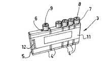
図1においてより具体的に示すように、分析ユニット2は、試薬用のカートリッジ3を備えており、カートリッジ3は5個の試薬容器4を備えている。各試薬容器4には、液体試薬が保持されている。 As shown more specifically in FIG. 1, the
各容器4は、単一の部材としてプラスチックで形成されており、ブロー成型により一体に形成された本体部5と首部6とを有する。各容器の本体部5は、略矩形の断面形状を有し、分析装置のキャリヤに係合するように形成された2つの略平行な長手側面と、相補形状を有する横側面とを有する。2つの隣接する容器の互いに向かい合った横側面は、互いに当接している。 Each container 4 is made of plastic as a single member, and has a
なお、各容器の首部6は閉鎖デバイス7を有しており、分析装置のキャリヤに設けられた相補形状を有するノッチに係合するように形成されている。各容器の閉鎖デバイスは、キャップ7により形成されている。キャップ7のスカート部は、その内側に、ねじ係合又はスナップ係合により容器の首部に固定するための手段を有し、少なくとも部分的に開口した底部に、破断可能な膜8を有する。破断可能な膜は複数のスリット9を有しており、このスリットにより、分析装置のプローブ又は針を容器内部に挿入・抜出することが簡単に行える。 It should be noted that the
これらの独立した複数の容器4は、容器の外周に設けられた粘着性ラベル11により互いに固定される。粘着性ラベル11は、その外面に、カートリッジについての情報(具体的には、例えば、使用する試薬及び実施する分析についての説明)を含むバーコード12を有する。 The plurality of independent containers 4 are fixed to each other by an
カートリッジ3は、3つの同一寸法の10ml容器と、1つの20ml容器と、1つの40ml容器とを備えている。この場合、実施する分析は、分析するサンプル中に目的の物質が存在するかどうかを判定するために、5種類の異なる試薬を異なる量にて使用することを必要としている。 The
しかし、本分析装置によって実施され得る分析のさまざまな性質を考慮すると、容器の個数、大きさ及び位置は適宜変更され得る。 However, considering the various properties of the analysis that can be performed by the present analyzer, the number, size and position of the containers can be varied as appropriate.
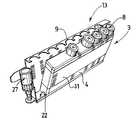
図2にさらに具体的に示すように、分析ユニット2は、プラスチック製のキャリヤ13をさらに備えている。キャリヤ13は、略鉛直方向に延びた背部壁14を有し、背部壁14の上側長辺15は、背部壁14に対して略垂直であり且つ背部壁14の長辺全体に亘って延びた、長辺側折り曲げフランジ16を有する。折り曲げフランジ16は、フランジの長さ方向に沿って均等な間隔で形成された9個のノッチ17を有する。各ノッチ17は、カートリッジの試薬容器の首部に係合するように形成されている。 As more specifically shown in FIG. 2, the
背部壁の底側長辺18は、背部壁14に対して略垂直であり且つ背部壁14の長辺全体に亘って延びた、長辺側折り曲げフランジ19を有する。折り曲げフランジ19は、背部壁14に対して略平行であり且つ背部壁14の長辺全体に亘って延びた縁部21を有する。 The bottom
縁部21及び背部壁14並びに折り曲げフランジ19が、座部22を形成する。座部22は、上方に開いており且つ少なくとも1つの試薬容器の底部を受け取るように形成されている。 The
なお、第1及び第2の折り曲げフランジは、それぞれキャリヤの頂部壁及び底部壁を形成する。 Note that the first and second bending flanges form the top and bottom walls of the carrier, respectively.
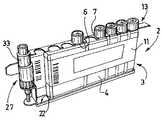
背部壁の分析装置側の横側端部23は、背部壁に対して略垂直であり且つこの横側端部上を部分的に延びた、横側折り曲げフランジ24を有する。なお、これら3つの折り曲げフランジは略同じ厚さを有する。 The
折り曲げフランジ24は、フランジ24に対して垂直外方に突き出た下側突起25及び上側突起26を有する。各突起は円形の貫通孔を有し、これら2つの貫通孔は同軸の関係に配置されている。 The bending
キャリヤ13は、攪拌システムをさらに有する。攪拌システムは、折り曲げフランジ24上に回転可能に設置された管状の支持部材27を有する。この管状の支持部材は、円筒状の本体部28を有する。本体部28は、外側表面に歯車29を有する。この歯車29は、分析装置の駆動機構により回転駆動されるように形成されている。円筒状の本体部28は、第1円筒部分30及びさらに小径の第2円筒部分31へと連続して延びている。これら2つの円筒部分は、円筒状本体部28と同軸の関係に配置されている。第1円筒部分30は上側突起26の孔の内側に係合し、第2円筒部分31は下側突起25の孔の内側に係合している。 The
なお、第2円筒部分31は、その自由端に、下側突起25の底部側表面に係合する留め部を有し、管状支持部材がキャリヤから脱落するのを防止している。 In addition, the 2nd
キャリヤは、折り曲げフランジ16と一体のハンドル32をさらに有し、これにより、分析装置のカートリッジの挿入及び除去ができる。 The carrier further has a
キャリヤ13にカートリッジ3を固定するには、まず各容器の底部をキャリヤの座部22の内側に係合し、次に各容器の首部を対応するノッチ17の内部に係合すればよい。なお、ノッチは、キャリヤに固定した容器の首部の軸方向に対して略垂直な平面を拡がるように設けられている。 In order to fix the
容器がキャリヤに確実に正しく固定されるように、各容器の上側と閉鎖キャップ7との間の距離は折り曲げフランジ16の厚さに略等しく、各ノッチ17の形状は各容器の首部の形状に対応した相補形状である。さらに、底部の折り曲げフランジ19と頂部の折り曲げフランジ16との距離を容器4の高さと略等しくしたことにより、容器がキャリヤに正しく固定される。 The distance between the upper side of each container and the
なお、ノッチ17はさらに、容器がキャリヤ13に対して横方向にずれるのを防止する。 The
図4に示すように、分析ユニットはさらに、管状支持部材27に脱着可能に取り付けられた管状コンテナ33を備えている。管状コンテナの軸は、管状支持部材の軸に対してずれている。好適には、管状コンテナは、その内壁に長手方向に延びたフィンを有し、分析する検体を捕捉するための磁気粒子を含む溶液を保持している。 As shown in FIG. 4, the analysis unit further includes a
なお、コンテナの外壁には長手方向に延びた溝が形成されており、この溝が管状支持部材の内壁に形成された相補リブに係合することにより、コンテナが支持部材に確実に固定される。 A groove extending in the longitudinal direction is formed on the outer wall of the container, and the container is securely fixed to the support member by engaging the complementary rib formed on the inner wall of the tubular support member. .
言うまでもないが、本発明は上記カートリッジの1つの実施形態のみに限定されるものではない。上記の実施形態は単なる例示に過ぎず、本発明はあらゆる変形例を含むものである。具体的には、上記とは異なる個数のノッチ及び/又は容器が設けられてもよい。さらに、キャリヤ13は金属製であってもよく、例えばステンレス鋼で形成されてもよい。この場合、容器中の試薬のレベルを検出するための熱伝導率及び電気伝導率が向上し得る。 Needless to say, the present invention is not limited to only one embodiment of the cartridge. The above embodiments are merely examples, and the present invention includes all modifications. Specifically, a different number of notches and / or containers may be provided. Further, the
2 分析ユニット
3 カートリッジ
4 試薬容器
5 本体部
6 首部
7 キャップ
8 膜
9 スリット
11 粘着性ラベル
13 キャリヤ
14 背部壁
15 上側長辺
16 折り曲げフランジ
17 ノッチ
18 底側長辺
19 折り曲げフランジ
21 縁部
22 座部
23 横側端部
24 横側折り曲げフランジ
25 下側突起
26 上側突起
27 支持部材
28 本体部
29 歯車
30 1円筒部分
31 第2円筒部分
32 ハンドル2
Claims (12)
Translated fromJapanese一体に組み立てられた複数の異なる容量のプラスチック製の試薬容器(4)を備えた試薬用カートリッジ(3)と、
前記カートリッジ(3)を受け取るためのプラスチック製のキャリヤ(13)と、を備え、
前記各試薬容器(4)は、本体部(5)と、閉鎖デバイス(7)が設けられた首部(6)とを有し、
前記キャリヤ(13)は、上方に開き且つ前記カートリッジ(3)を形成する試薬容器(4)の底部を受け取るように形成された座部(22)と、上側長辺(15)を有する略鉛直方向に延びる背部壁(14)と、を有し、
前記背部壁(14)は、前記上側長辺(15)から前記背部壁(14)に対して略垂直に延び且つ複数のノッチ(17)が設けられた折り曲げフランジ(16)を有し、該複数のノッチ(17)は該折り曲げフランジ(16)の長手方向に均等な間隔で配置され、
前記折り曲げフランジ(16)と前記座部(22)との間の距離が前記試薬容器(4)の前記本体部(5)と略同一であり、
前記各ノッチ(17)は、前記試薬容器(4)の底部が前記座部(22)内に受け取られると前記試薬容器(4)の前記首部(6)に係合するように構成され、
2つの隣接する首部(6)の軸間の距離は、2つの隣接するノッチ(17)の間の距離の数倍である
ことを特徴とする分析ユニット。In the analysis unit used in the analyzer,
A reagent cartridge (3) comprising a plurality ofdifferent volume plastic reagent containers (4) assembled together;
A plastic carrier (13) for receiving the cartridge (3),
Each reagent container (4) has a body (5) and a neck (6) provided with a closure device (7),
The carrier (13) is generally vertical having a seat (22) formed to receive the bottom of a reagent container (4) that opens upward and forms the cartridge (3), and an upper long side (15). A back wall (14) extending in a direction,
It said back wall (14) has a flange bent and a plurality of notches extending substantially perpendicularly (17) is provided (16) with respect to the back wall from said upper long side (15) (14),said The plurality of notches (17) are arranged at equal intervals in the longitudinal direction of the bent flange (16),
The distance between the bent flange (16) and the seat (22) is substantially the same as the body (5) of the reagent container (4);
Each notch (17) is configured to engage the neck (6) of the reagent container (4) when the bottom of the reagent container (4) is received in the seat (22);
An analysis unit characterized in thatthe distance between the axes of two adjacent necks (6) is several times the distance between two adjacent notches (17) .
前記背部壁(14)の底側長辺(18)は前記背部壁(14)に対して略垂直の折り曲
げフランジ(19)を有し、前記折り曲げフランジ(19)は、前記背部壁に対して略平行である縁部(21)を有し、前記縁部及び前記背部壁並びに前記底側長辺(18)の前記折り曲げフランジは、前記試薬容器の底部を受け取るための前記座部(22)を形成することを特徴とする分析ユニット。The analysis unit according to claim1 ,
The bottom long side (18) of the back wall (14) has a bending flange (19) substantially perpendicular to the back wall (14), and the bending flange (19) is against the back wall. The seat (22) having an edge (21) that is substantially parallel and wherein the bent flange of the edge and the back wall and the bottom long side (18) receives the bottom of the reagent container. Analytical unit characterized by forming.
前記キャリヤ(13)は攪拌システムを有し、前記攪拌システムは管状の支持部材(27)を備えており、前記管状支持部材(27)は、その軸が鉛直方向と一致し且つ回転可能な様態で前記キャリヤに設置されており、前記支持部材はその外側表面に回転駆動手段(29)を有する
ことを特徴とする分析ユニット。The analysis unit according to claim 1or 2 ,
The carrier (13) has an agitation system, and the agitation system includes a tubular support member (27). The tubular support member (27) is configured such that its axis coincides with the vertical direction and is rotatable. The analysis unit is installed in the carrier, and the support member has rotation driving means (29) on the outer surface thereof.
前記回転駆動手段は、分析装置の駆動機構によって回転駆動されるように形成された歯車(29)を含む
ことを特徴とする分析ユニット。The analysis unit according to claim3 ,
The analysis unit characterized in that the rotation driving means includes a gear (29) formed so as to be rotationally driven by a drive mechanism of the analyzer.
前記容器(4)の各々は、単一の部材としてプラスチックで形成され、前記各容器(4)の前記首部(6)は、前記各容器の本体部(5)と一体的にブロー成型されている
ことを特徴とする分析ユニット。In the analysis unit according to any one of claims 1 to4 ,
Each of the containers (4) is formed of plastic as a single member, and the neck (6) of each container (4) is blow-molded integrally with the main body (5) of each container. An analysis unit characterized by
前記各容器は、前記キャリヤ(13)に係合するように形成された2つの略平行な長手側面と、相補形状を有する2つの横側面とを有し、2つの隣接する容器の前記横側面は互いに向かい合い且つ互いに当接している、
ことを特徴とする分析ユニット。In the analysis unit according to any one of claims 1 to5 ,
Each container has two generally parallel longitudinal sides formed to engage the carrier (13) and two lateral sides having complementary shapes, the lateral sides of two adjacent containers. Are facing each other and abutting each other,
An analysis unit characterized by that.
前記容器(4)は、前記容器の外周に設けられた粘着性ストリップ(11)によって互いに固定されている
ことを特徴とする分析ユニット。In the analysis unit according to any one of claims 1 to6 ,
The analysis unit characterized in that the container (4) is fixed to each other by an adhesive strip (11) provided on the outer periphery of the container.
前記粘着性ラベル(11)は、その外面に、前記カートリッジについての情報を含むラベルを形成し、前記情報は例えばバーコード(12)の形態で提供される
ことを特徴とする分析ユニット。The analysis unit according to claim7 ,
The said adhesive label (11) forms the label containing the information about the said cartridge in the outer surface, The said information is provided in the form of a barcode (12), for example, The analysis unit characterized by the above-mentioned.
前記各容器の閉鎖デバイスはキャップ(7)により形成され、前記キャップのスカート部は、その内側に、ねじ係合又はスナップ係合により前記容器の首部に固定するための手段を有し、少なくとも部分的に開口した底部に破断可能な膜を有する
ことを特徴とする分析ユニット。In the analysis unit according to any one of claims 1 to8 ,
The closure device of each container is formed by a cap (7), the skirt of the cap having means on its inside for fixing to the neck of the container by screw engagement or snap engagement, at least partly Analyzing unit, characterized in that it has a breakable membrane at the bottom that is open.
前記分析ユニットは、前記管状支持部材(27)内に設けられた管状コンテナ(33)
をさらに備え、
前記管状コンテナの軸は、前記管状支持部材の軸に対してずれている
ことを特徴とする分析ユニット。The analysis unit according to claim3 or4 ,
The analysis unit includes a tubular container (33) provided in the tubular support member (27).
Further comprising
The analysis unit characterized in that the axis of the tubular container is offset with respect to the axis of the tubular support member.
前記コンテナ(33)の内壁は、長手方向に延びたフィンを有している
ことを特徴とする分析ユニット。The analysis unit according to claim10 ,
The analysis unit characterized in that the inner wall of the container (33) has fins extending in the longitudinal direction.
前記コンテナ(33)の外壁は長手方向に延びた溝を有し、この溝が前記管状支持部材(27)の内壁に設けられた相補リブに係合することにより、前記コンテナ(33)が前記支持部材(27)に確実に固定される
ことを特徴とする分析ユニット。The analysis unit according to claim10 or11 ,
The outer wall of the container (33) has a groove extending in the longitudinal direction, and the groove engages with a complementary rib provided on the inner wall of the tubular support member (27), whereby the container (33) is An analysis unit characterized in that it is securely fixed to the support member (27).
Applications Claiming Priority (3)
| Application Number | Priority Date | Filing Date | Title |
|---|---|---|---|
| FR0606685AFR2904114B1 (en) | 2006-07-21 | 2006-07-21 | CARTRIDGE FOR REACTIVE PRODUCTS FOR USE IN ANALYTICAL APPARATUSES, CARRIER FOR RECEIVING THIS CARTRIDGE, AND ANALYSIS ASSEMBLY COMPRISING SAID CARTRIDGE AND HOLDER |
| FR0606685 | 2006-07-21 | ||
| PCT/FR2007/001241WO2008009821A1 (en) | 2006-07-21 | 2007-07-19 | Analysis package to be used in analysis devices |
Publications (2)
| Publication Number | Publication Date |
|---|---|
| JP2009544959A JP2009544959A (en) | 2009-12-17 |
| JP5257361B2true JP5257361B2 (en) | 2013-08-07 |
Family
ID=37776434
Family Applications (1)
| Application Number | Title | Priority Date | Filing Date |
|---|---|---|---|
| JP2009521290AActiveJP5257361B2 (en) | 2006-07-21 | 2007-07-19 | Analysis unit used in analyzer |
Country Status (14)
| Country | Link |
|---|---|
| US (1) | US8926921B2 (en) |
| EP (1) | EP2043786B1 (en) |
| JP (1) | JP5257361B2 (en) |
| KR (1) | KR101372984B1 (en) |
| CN (1) | CN101489681B (en) |
| AU (1) | AU2007274989B2 (en) |
| BR (1) | BRPI0714389B1 (en) |
| CA (1) | CA2657281C (en) |
| DK (1) | DK2043786T3 (en) |
| ES (1) | ES2622063T3 (en) |
| FR (1) | FR2904114B1 (en) |
| IL (1) | IL196419A (en) |
| PL (1) | PL2043786T3 (en) |
| WO (1) | WO2008009821A1 (en) |
Families Citing this family (32)
| Publication number | Priority date | Publication date | Assignee | Title |
|---|---|---|---|---|
| FR2934506B1 (en)* | 2008-07-29 | 2011-04-08 | Biocode Hycel France Sa | CONTAINER FOR REACTIVE PRODUCTS |
| EP2352634B1 (en) | 2008-12-05 | 2014-10-15 | F. Hoffmann-La Roche AG | Method for manufacturing a reagent container unit and reagent container unit |
| EP2287621A1 (en)* | 2009-08-19 | 2011-02-23 | Roche Diagnostics GmbH | Reagent kit for analyzing apparatus |
| US9375714B2 (en)* | 2009-12-21 | 2016-06-28 | Abbott Laboratories | Container having gas scrubber insert for automated clinical analyzer |
| EP2371731A1 (en) | 2010-03-31 | 2011-10-05 | Roche Diagnostics GmbH | Reagent kit with transit support |
| CN103071556B (en)* | 2012-06-15 | 2014-11-26 | 郑州安图生物工程股份有限公司 | Reagent bottle and holder for medical analyzer |
| DE102012222828B4 (en) | 2012-12-11 | 2025-05-28 | Agilent Technologies, Inc. - A Delaware Corporation - | Sample separation device, arrangement and method for supplying liquid to a sample separation device |
| FR3000803B1 (en)* | 2013-01-04 | 2018-05-25 | Immunodiagnostic Systems France | ANALYSIS ASSEMBLY FOR ANALYSIS APPARATUS |
| US10456786B2 (en) | 2013-03-12 | 2019-10-29 | Abbott Laboratories | Septums and related methods |
| USD962471S1 (en) | 2013-03-13 | 2022-08-30 | Abbott Laboratories | Reagent container |
| US9535082B2 (en) | 2013-03-13 | 2017-01-03 | Abbott Laboratories | Methods and apparatus to agitate a liquid |
| USD978375S1 (en) | 2013-03-13 | 2023-02-14 | Abbott Laboratories | Reagent container |
| US10058866B2 (en) | 2013-03-13 | 2018-08-28 | Abbott Laboratories | Methods and apparatus to mitigate bubble formation in a liquid |
| WO2014181896A1 (en)* | 2013-05-06 | 2014-11-13 | (주)실리콘화일 | Organic substance analysis apparatus including membrane based multiple tubes |
| CN103487595A (en)* | 2013-10-14 | 2014-01-01 | 中国科学院苏州生物医学工程技术研究所 | Kit for full-automatic chemiluminiscence immunity analyzer |
| USD765875S1 (en)* | 2013-10-25 | 2016-09-06 | Sysmex Corporation | Reagent set |
| CN104006984A (en)* | 2014-06-04 | 2014-08-27 | 上海宏莘科技发展有限公司 | Digital type fully-automatic intelligent sampling machine |
| WO2016130964A1 (en) | 2015-02-13 | 2016-08-18 | Abbott Laboratories | Decapping and capping apparatus, systems and methods for use in diagnostic analyzers |
| CN104826684A (en)* | 2015-05-14 | 2015-08-12 | 章丘市义弘广医疗器械有限公司 | Sample frame |
| CN105203781A (en)* | 2015-09-16 | 2015-12-30 | 江苏奥迪康医学科技股份有限公司 | Clinical chemistry integrated and combined multi-reagent-strip detection device and method |
| EP3192583A1 (en) | 2016-01-12 | 2017-07-19 | ETH Zurich | Apparatus and process for the automated chemical synthesis of compounds |
| CN106124241B (en)* | 2016-08-10 | 2018-08-07 | 山东新马制药装备有限公司 | The sampling device of solid hard capsule |
| CN110494757B (en)* | 2017-03-24 | 2024-03-15 | 简·探针公司 | System and method for capacitive fluid level detection and handling of containers |
| USD855211S1 (en)* | 2017-05-10 | 2019-07-30 | Integrated Lab Solutions, Inc. | Carrier for multiple specimen bottles |
| SE542103C2 (en)* | 2017-11-09 | 2020-02-25 | Hemocue Ab | A microcuvette holder, an analysis apparatus comprising the holder and method for analysing a blood sample using the analysis apparatus |
| CN107934143A (en)* | 2017-11-27 | 2018-04-20 | 苏州信诺泰克医疗科技有限公司 | Magnetic bead reagent container and kit |
| CN115092439B (en) | 2017-12-22 | 2024-12-17 | 西氏医药服务公司 | Packaging system for aseptically filling small-volume vials |
| CN112752962B (en)* | 2018-12-14 | 2025-01-03 | 莱卡生物系统墨尔本私人有限公司 | Reagent test kit |
| RU203863U1 (en)* | 2019-05-23 | 2021-04-23 | Анна Михайловна Лутова | AUTOMOTIVE CONTAINER FOR TRANSPORTATION OF ANALYSIS |
| CN111999159A (en)* | 2019-05-27 | 2020-11-27 | 深圳迈瑞生物医疗电子股份有限公司 | Sample racks, sample mixing systems and sample analyzers |
| US11794189B2 (en) | 2020-03-25 | 2023-10-24 | Gen-Probe Incorporated | Fluid container |
| WO2023182166A1 (en)* | 2022-03-22 | 2023-09-28 | 富士フイルム株式会社 | Liquid container |
Family Cites Families (30)
| Publication number | Priority date | Publication date | Assignee | Title |
|---|---|---|---|---|
| JPS542150U (en) | 1977-06-08 | 1979-01-09 | ||
| US4234103A (en)* | 1978-03-31 | 1980-11-18 | Baxter Travenol Laboratories, Inc. | Diagnostic reagent dispensing bottle |
| JPS55148558A (en)* | 1979-05-07 | 1980-11-19 | Tokan Kogyo Co Ltd | Method of fixing ampoule into vessel and its frame body |
| US4350253A (en)* | 1980-06-19 | 1982-09-21 | Panlmatic Company | Bottle storage rack |
| US4970053A (en)* | 1986-07-11 | 1990-11-13 | Beckman Instruments, Inc. | Reagent cartridge |
| US5075082A (en)* | 1986-07-11 | 1991-12-24 | Beckman Instruments, Inc. | Reagent cartridge |
| DE4023194A1 (en)* | 1990-07-20 | 1992-01-23 | Kodak Ag | DEVICE WITH SEVERAL RECEIVER ARRANGEMENTS FOR LIQUID-FILLED CONTAINERS |
| JPH0617769Y2 (en)* | 1991-05-17 | 1994-05-11 | 幸雄 木村 | Bottle carrier |
| AU2382792A (en)* | 1991-07-22 | 1993-02-23 | Abbott Laboratories | Reusable seal for diagnostic test reagent pack |
| JP2565598Y2 (en)* | 1991-10-24 | 1998-03-18 | 釜屋化学工業株式会社 | Stand for holding bag containers |
| TW223593B (en)* | 1992-04-09 | 1994-05-11 | Hoffmann La Roche | |
| US5344036A (en)* | 1992-06-04 | 1994-09-06 | Akzo N.V. | Container system |
| US5322668A (en)* | 1993-07-01 | 1994-06-21 | Eastman Kodak Company | Locked bottle holder |
| JP2605131Y2 (en)* | 1993-08-23 | 2000-06-26 | 株式会社細川洋行 | Flexible container retainer |
| DE19540877C2 (en) | 1995-11-02 | 1998-02-26 | Byk Sangtec Diagnostica | Modular reagent cartridge |
| CA2196839A1 (en)* | 1996-02-08 | 1997-08-09 | Peter W. Heyman | Modular rack system for use in packaging and handling syringe barrels |
| US5655673A (en)* | 1996-05-03 | 1997-08-12 | Robbins Industries Inc. | Large spice jar rack |
| AU4093699A (en)* | 1998-05-22 | 1999-12-13 | Nichols Institute Diagnostics | Magnetic particle suspending device, apparatus and methods for using same |
| WO2000031535A2 (en)* | 1998-11-25 | 2000-06-02 | Quest Diagnostics Investments Incorporated | Thyroid peroxidase autoantibody assay compositions, method and kit |
| CN2451221Y (en)* | 2000-10-21 | 2001-10-03 | 陈康 | Combined test-tube stand |
| JP4795580B2 (en)* | 2001-08-30 | 2011-10-19 | シスメックス株式会社 | Reagent management method and analyzer |
| US7666363B2 (en)* | 2001-09-05 | 2010-02-23 | Quest Diagnostics Investments Incorporated | Reagent cartridge |
| JP4658411B2 (en)* | 2001-09-11 | 2011-03-23 | シスメックス株式会社 | Flow path connection mechanism and reagent holder provided with the same |
| JP2004067122A (en)* | 2002-08-02 | 2004-03-04 | Fp Corp | Packaging container |
| JP2004163319A (en) | 2002-11-14 | 2004-06-10 | Sysmex Corp | Liquid container unit and connection mechanism |
| NZ523320A (en) | 2002-12-20 | 2004-06-25 | Kohler New Zealand Ltd | A spa bath fitting and spa bath |
| DE10308362A1 (en)* | 2003-02-27 | 2004-09-09 | Roche Diagnostics Gmbh | System for automatic opening of test tubes |
| JP4146780B2 (en)* | 2003-10-17 | 2008-09-10 | 株式会社日立ハイテクノロジーズ | Reagent cassette and automatic analyzer using the same |
| JP2005164509A (en)* | 2003-12-05 | 2005-06-23 | Hitachi High-Technologies Corp | Reagent container |
| DE10360526A1 (en)* | 2003-12-22 | 2005-07-14 | Roche Diagnostics Gmbh | Reagent cassette with reagent container for particle-containing reagent for its noninvasive homogenization |
- 2006
- 2006-07-21FRFR0606685Apatent/FR2904114B1/enactiveActive
- 2007
- 2007-07-19EPEP07823303.8Apatent/EP2043786B1/enactiveActive
- 2007-07-19BRBRPI0714389-3Apatent/BRPI0714389B1/enactiveIP Right Grant
- 2007-07-19CACA2657281Apatent/CA2657281C/enactiveActive
- 2007-07-19KRKR1020097002502Apatent/KR101372984B1/enactiveActive
- 2007-07-19USUS12/374,508patent/US8926921B2/enactiveActive
- 2007-07-19AUAU2007274989Apatent/AU2007274989B2/enactiveActive
- 2007-07-19PLPL07823303Tpatent/PL2043786T3/enunknown
- 2007-07-19JPJP2009521290Apatent/JP5257361B2/enactiveActive
- 2007-07-19CNCN2007800272860Apatent/CN101489681B/enactiveActive
- 2007-07-19DKDK07823303.8Tpatent/DK2043786T3/enactive
- 2007-07-19WOPCT/FR2007/001241patent/WO2008009821A1/enactiveApplication Filing
- 2007-07-19ESES07823303.8Tpatent/ES2622063T3/enactiveActive
- 2009
- 2009-01-08ILIL196419Apatent/IL196419A/enactiveIP Right Grant
Also Published As
| Publication number | Publication date |
|---|---|
| BRPI0714389A2 (en) | 2013-04-02 |
| BRPI0714389B1 (en) | 2018-06-05 |
| IL196419A0 (en) | 2009-09-22 |
| KR20090051169A (en) | 2009-05-21 |
| EP2043786A1 (en) | 2009-04-08 |
| EP2043786B1 (en) | 2016-11-30 |
| FR2904114B1 (en) | 2008-10-17 |
| FR2904114A1 (en) | 2008-01-25 |
| JP2009544959A (en) | 2009-12-17 |
| CN101489681B (en) | 2012-07-25 |
| AU2007274989B2 (en) | 2012-04-19 |
| US8926921B2 (en) | 2015-01-06 |
| CA2657281A1 (en) | 2008-01-24 |
| US20100034700A1 (en) | 2010-02-11 |
| CN101489681A (en) | 2009-07-22 |
| KR101372984B1 (en) | 2014-03-11 |
| CA2657281C (en) | 2013-10-01 |
| DK2043786T3 (en) | 2017-03-13 |
| WO2008009821A1 (en) | 2008-01-24 |
| AU2007274989A1 (en) | 2008-01-24 |
| IL196419A (en) | 2013-10-31 |
| ES2622063T3 (en) | 2017-07-05 |
| PL2043786T3 (en) | 2017-07-31 |
Similar Documents
| Publication | Publication Date | Title |
|---|---|---|
| JP5257361B2 (en) | Analysis unit used in analyzer | |
| US8529847B2 (en) | Reagent kit for analyzing apparatus | |
| JP6411366B2 (en) | Analysis unit for analyzer | |
| JP7132366B2 (en) | Sample racks, sample rack adapters and automated analyzers | |
| CN215866737U (en) | Reagent test kit | |
| CN216387081U (en) | Kit and POCT blood cell analyzer | |
| CN216350758U (en) | Kit and assembly seat | |
| CN215866734U (en) | Reagent kit | |
| CN216747766U (en) | Reagent kit | |
| CN215180265U (en) | Microporous sheet and kit | |
| CN215866732U (en) | Kit and assembly seat | |
| CN215525839U (en) | Kit and sample detection device | |
| CN215180264U (en) | Kit and sample detection device | |
| CN215866735U (en) | Kit and POCT (point of care testing) blood fine analyzer | |
| CN216350759U (en) | Reagent kit | |
| CN215866265U (en) | Reagent kit | |
| CN215180266U (en) | Kit and assembly seat | |
| CN215575199U (en) | Kit and sample detection device | |
| CN215180226U (en) | Reagent kit | |
| CN215525841U (en) | Kit and detection cup assembly | |
| CN113686760B (en) | Kit and POCT blood cell analyzer |
Legal Events
| Date | Code | Title | Description |
|---|---|---|---|
| A621 | Written request for application examination | Free format text:JAPANESE INTERMEDIATE CODE: A621 Effective date:20100524 | |
| A977 | Report on retrieval | Free format text:JAPANESE INTERMEDIATE CODE: A971007 Effective date:20120323 | |
| A131 | Notification of reasons for refusal | Free format text:JAPANESE INTERMEDIATE CODE: A131 Effective date:20120403 | |
| A521 | Request for written amendment filed | Free format text:JAPANESE INTERMEDIATE CODE: A523 Effective date:20120703 | |
| A131 | Notification of reasons for refusal | Free format text:JAPANESE INTERMEDIATE CODE: A131 Effective date:20121204 | |
| A521 | Request for written amendment filed | Free format text:JAPANESE INTERMEDIATE CODE: A523 Effective date:20130228 | |
| TRDD | Decision of grant or rejection written | ||
| A01 | Written decision to grant a patent or to grant a registration (utility model) | Free format text:JAPANESE INTERMEDIATE CODE: A01 Effective date:20130326 | |
| A61 | First payment of annual fees (during grant procedure) | Free format text:JAPANESE INTERMEDIATE CODE: A61 Effective date:20130408 | |
| FPAY | Renewal fee payment (event date is renewal date of database) | Free format text:PAYMENT UNTIL: 20160502 Year of fee payment:3 | |
| R150 | Certificate of patent or registration of utility model | Ref document number:5257361 Country of ref document:JP Free format text:JAPANESE INTERMEDIATE CODE: R150 Free format text:JAPANESE INTERMEDIATE CODE: R150 | |
| S531 | Written request for registration of change of domicile | Free format text:JAPANESE INTERMEDIATE CODE: R313531 | |
| S533 | Written request for registration of change of name | Free format text:JAPANESE INTERMEDIATE CODE: R313533 | |
| R350 | Written notification of registration of transfer | Free format text:JAPANESE INTERMEDIATE CODE: R350 | |
| R250 | Receipt of annual fees | Free format text:JAPANESE INTERMEDIATE CODE: R250 | |
| R250 | Receipt of annual fees | Free format text:JAPANESE INTERMEDIATE CODE: R250 | |
| R250 | Receipt of annual fees | Free format text:JAPANESE INTERMEDIATE CODE: R250 | |
| R250 | Receipt of annual fees | Free format text:JAPANESE INTERMEDIATE CODE: R250 | |
| R250 | Receipt of annual fees | Free format text:JAPANESE INTERMEDIATE CODE: R250 | |
| R250 | Receipt of annual fees | Free format text:JAPANESE INTERMEDIATE CODE: R250 | |
| R250 | Receipt of annual fees | Free format text:JAPANESE INTERMEDIATE CODE: R250 | |
| R250 | Receipt of annual fees | Free format text:JAPANESE INTERMEDIATE CODE: R250 | |
| R250 | Receipt of annual fees | Free format text:JAPANESE INTERMEDIATE CODE: R250 | |
| R250 | Receipt of annual fees | Free format text:JAPANESE INTERMEDIATE CODE: R250 |