JP5256269B2 - Data generation apparatus, data generation apparatus control method, and program - Google Patents
Data generation apparatus, data generation apparatus control method, and programDownload PDFInfo
- Publication number
- JP5256269B2 JP5256269B2JP2010242817AJP2010242817AJP5256269B2JP 5256269 B2JP5256269 B2JP 5256269B2JP 2010242817 AJP2010242817 AJP 2010242817AJP 2010242817 AJP2010242817 AJP 2010242817AJP 5256269 B2JP5256269 B2JP 5256269B2
- Authority
- JP
- Japan
- Prior art keywords
- data
- player
- time
- sample
- setting screen
- Prior art date
- Legal status (The legal status is an assumption and is not a legal conclusion. Google has not performed a legal analysis and makes no representation as to the accuracy of the status listed.)
- Active
Links
Images


Classifications
- A—HUMAN NECESSITIES
- A63—SPORTS; GAMES; AMUSEMENTS
- A63F—CARD, BOARD, OR ROULETTE GAMES; INDOOR GAMES USING SMALL MOVING PLAYING BODIES; VIDEO GAMES; GAMES NOT OTHERWISE PROVIDED FOR
- A63F13/00—Video games, i.e. games using an electronically generated display having two or more dimensions
- A63F13/40—Processing input control signals of video game devices, e.g. signals generated by the player or derived from the environment
- A63F13/42—Processing input control signals of video game devices, e.g. signals generated by the player or derived from the environment by mapping the input signals into game commands, e.g. mapping the displacement of a stylus on a touch screen to the steering angle of a virtual vehicle
- A63F13/428—Processing input control signals of video game devices, e.g. signals generated by the player or derived from the environment by mapping the input signals into game commands, e.g. mapping the displacement of a stylus on a touch screen to the steering angle of a virtual vehicle involving motion or position input signals, e.g. signals representing the rotation of an input controller or a player's arm motions sensed by accelerometers or gyroscopes
- A—HUMAN NECESSITIES
- A63—SPORTS; GAMES; AMUSEMENTS
- A63F—CARD, BOARD, OR ROULETTE GAMES; INDOOR GAMES USING SMALL MOVING PLAYING BODIES; VIDEO GAMES; GAMES NOT OTHERWISE PROVIDED FOR
- A63F13/00—Video games, i.e. games using an electronically generated display having two or more dimensions
- A63F13/40—Processing input control signals of video game devices, e.g. signals generated by the player or derived from the environment
- A63F13/44—Processing input control signals of video game devices, e.g. signals generated by the player or derived from the environment involving timing of operations, e.g. performing an action within a time slot
- A—HUMAN NECESSITIES
- A63—SPORTS; GAMES; AMUSEMENTS
- A63F—CARD, BOARD, OR ROULETTE GAMES; INDOOR GAMES USING SMALL MOVING PLAYING BODIES; VIDEO GAMES; GAMES NOT OTHERWISE PROVIDED FOR
- A63F13/00—Video games, i.e. games using an electronically generated display having two or more dimensions
- A63F13/60—Generating or modifying game content before or while executing the game program, e.g. authoring tools specially adapted for game development or game-integrated level editor
- A63F13/67—Generating or modifying game content before or while executing the game program, e.g. authoring tools specially adapted for game development or game-integrated level editor adaptively or by learning from player actions, e.g. skill level adjustment or by storing successful combat sequences for re-use
- A—HUMAN NECESSITIES
- A63—SPORTS; GAMES; AMUSEMENTS
- A63F—CARD, BOARD, OR ROULETTE GAMES; INDOOR GAMES USING SMALL MOVING PLAYING BODIES; VIDEO GAMES; GAMES NOT OTHERWISE PROVIDED FOR
- A63F13/00—Video games, i.e. games using an electronically generated display having two or more dimensions
- A63F13/80—Special adaptations for executing a specific game genre or game mode
- A63F13/814—Musical performances, e.g. by evaluating the player's ability to follow a notation
- A—HUMAN NECESSITIES
- A63—SPORTS; GAMES; AMUSEMENTS
- A63F—CARD, BOARD, OR ROULETTE GAMES; INDOOR GAMES USING SMALL MOVING PLAYING BODIES; VIDEO GAMES; GAMES NOT OTHERWISE PROVIDED FOR
- A63F13/00—Video games, i.e. games using an electronically generated display having two or more dimensions
- A63F13/20—Input arrangements for video game devices
- A63F13/21—Input arrangements for video game devices characterised by their sensors, purposes or types
- A63F13/213—Input arrangements for video game devices characterised by their sensors, purposes or types comprising photodetecting means, e.g. cameras, photodiodes or infrared cells
- A—HUMAN NECESSITIES
- A63—SPORTS; GAMES; AMUSEMENTS
- A63F—CARD, BOARD, OR ROULETTE GAMES; INDOOR GAMES USING SMALL MOVING PLAYING BODIES; VIDEO GAMES; GAMES NOT OTHERWISE PROVIDED FOR
- A63F2300/00—Features of games using an electronically generated display having two or more dimensions, e.g. on a television screen, showing representations related to the game
- A63F2300/10—Features of games using an electronically generated display having two or more dimensions, e.g. on a television screen, showing representations related to the game characterized by input arrangements for converting player-generated signals into game device control signals
- A63F2300/1087—Features of games using an electronically generated display having two or more dimensions, e.g. on a television screen, showing representations related to the game characterized by input arrangements for converting player-generated signals into game device control signals comprising photodetecting means, e.g. a camera
- A—HUMAN NECESSITIES
- A63—SPORTS; GAMES; AMUSEMENTS
- A63F—CARD, BOARD, OR ROULETTE GAMES; INDOOR GAMES USING SMALL MOVING PLAYING BODIES; VIDEO GAMES; GAMES NOT OTHERWISE PROVIDED FOR
- A63F2300/00—Features of games using an electronically generated display having two or more dimensions, e.g. on a television screen, showing representations related to the game
- A63F2300/60—Methods for processing data by generating or executing the game program
- A63F2300/6009—Methods for processing data by generating or executing the game program for importing or creating game content, e.g. authoring tools during game development, adapting content to different platforms, use of a scripting language to create content
- A—HUMAN NECESSITIES
- A63—SPORTS; GAMES; AMUSEMENTS
- A63F—CARD, BOARD, OR ROULETTE GAMES; INDOOR GAMES USING SMALL MOVING PLAYING BODIES; VIDEO GAMES; GAMES NOT OTHERWISE PROVIDED FOR
- A63F2300/00—Features of games using an electronically generated display having two or more dimensions, e.g. on a television screen, showing representations related to the game
- A63F2300/60—Methods for processing data by generating or executing the game program
- A63F2300/6027—Methods for processing data by generating or executing the game program using adaptive systems learning from user actions, e.g. for skill level adjustment
- A—HUMAN NECESSITIES
- A63—SPORTS; GAMES; AMUSEMENTS
- A63F—CARD, BOARD, OR ROULETTE GAMES; INDOOR GAMES USING SMALL MOVING PLAYING BODIES; VIDEO GAMES; GAMES NOT OTHERWISE PROVIDED FOR
- A63F2300/00—Features of games using an electronically generated display having two or more dimensions, e.g. on a television screen, showing representations related to the game
- A63F2300/60—Methods for processing data by generating or executing the game program
- A63F2300/63—Methods for processing data by generating or executing the game program for controlling the execution of the game in time
- A63F2300/638—Methods for processing data by generating or executing the game program for controlling the execution of the game in time according to the timing of operation or a time limit
- A—HUMAN NECESSITIES
- A63—SPORTS; GAMES; AMUSEMENTS
- A63F—CARD, BOARD, OR ROULETTE GAMES; INDOOR GAMES USING SMALL MOVING PLAYING BODIES; VIDEO GAMES; GAMES NOT OTHERWISE PROVIDED FOR
- A63F2300/00—Features of games using an electronically generated display having two or more dimensions, e.g. on a television screen, showing representations related to the game
- A63F2300/60—Methods for processing data by generating or executing the game program
- A63F2300/66—Methods for processing data by generating or executing the game program for rendering three dimensional images
- A—HUMAN NECESSITIES
- A63—SPORTS; GAMES; AMUSEMENTS
- A63F—CARD, BOARD, OR ROULETTE GAMES; INDOOR GAMES USING SMALL MOVING PLAYING BODIES; VIDEO GAMES; GAMES NOT OTHERWISE PROVIDED FOR
- A63F2300/00—Features of games using an electronically generated display having two or more dimensions, e.g. on a television screen, showing representations related to the game
- A63F2300/80—Features of games using an electronically generated display having two or more dimensions, e.g. on a television screen, showing representations related to the game specially adapted for executing a specific type of game
- A63F2300/8047—Music games
Landscapes
- Engineering & Computer Science (AREA)
- Multimedia (AREA)
- Human Computer Interaction (AREA)
- Processing Or Creating Images (AREA)
Description
Translated fromJapanese本発明は、データ生成装置、データ生成装置の制御方法、及びプログラムに関する。 The present invention relates to a data generation device, a control method for the data generation device, and a program.
プレイヤをカメラで撮影して得られる画像(撮影画像)を用いたゲームが知られている。例えば、特許文献1には、撮影画像に基づいてプレイヤの動作を解析し、プレイヤが、楽曲に合わせてダンスを踊るキャラクタと同じ動作をすることを目指すゲームが記載されている。特許文献1の技術においては、ゲーム装置がプレイヤの動作を判定する時点を示す情報と、この時点においてプレイヤがすべき動きを特定する情報と、を対応付けてなる基準データに基づいて、プレイヤの動きが評価される。 A game using an image (photographed image) obtained by photographing a player with a camera is known. For example,
上記のように、プレイヤの動きを評価するために用いられる基準データを生成する場合には、楽曲のテンポだけではなく、各時点においてプレイヤが動かす部位の位置も考慮する必要があるので、基準データの生成には煩雑な作業を要するという問題があった。 As described above, when generating the reference data used for evaluating the movement of the player, it is necessary to consider not only the tempo of the music but also the position of the part that the player moves at each time point. There is a problem that a complicated operation is required to generate.
本発明は、上記課題に鑑みてなされたものであって、その目的は、プレイヤの動きを評価するゲームに用いられる基準データを効率良く生成することが可能なデータ生成装置、データ生成装置の制御方法、及びプログラムを提供することである。 The present invention has been made in view of the above problems, and an object of the present invention is to provide a data generation device capable of efficiently generating reference data used in a game for evaluating a player's movement, and control of the data generation device. A method and program are provided.
上記課題を解決するために、本発明に係るデータ生成装置は、楽曲データの再生期間内に設定される基準時点に関する情報と、前記基準時点においてプレイヤの部位があるべき基準位置に関する情報と、を対応付けてなる基準データに基づいて、前記楽曲データの再生期間内に行われるプレイヤの動作を評価するゲームにおいて用いられる前記基準データを生成するためのデータ生成装置であって、前記楽曲データの再生期間内の各時点における前記プレイヤの見本姿勢に関する見本データを記憶する手段から前記見本データを取得する見本データ取得手段と、前記基準データを生成するための設定画面を表示する表示手段と、前記設定画面において、前記楽曲データの再生期間内における時点の指定を受け付ける指定受付手段と、前記指定された時点における前記プレイヤの見本姿勢を案内する見本画像を、前記見本データに基づいて前記設定画面に表示させる表示制御手段と、前記指定された時点と、前記指定された時点の前記プレイヤの見本姿勢における前記部位の位置と、に基づいて前記基準データを生成する基準データ生成手段と、を含むことを特徴とする。 In order to solve the above-described problem, a data generation device according to the present invention includes information on a reference time set within a reproduction period of music data, and information on a reference position where a player's part should be at the reference time. A data generation device for generating the reference data used in a game for evaluating a player's action performed within a reproduction period of the music data based on the associated reference data, the reproduction of the music data Sample data acquisition means for acquiring the sample data from means for storing sample data relating to the sample posture of the player at each point in time, display means for displaying a setting screen for generating the reference data, and the setting On the screen, designation accepting means for accepting designation of a time point within the reproduction period of the music data, and the designation Display control means for displaying a sample image for guiding the sample posture of the player at the specified time on the setting screen based on the sample data, the specified time, and the sample of the player at the specified time Reference data generating means for generating the reference data based on the position of the part in the posture.
また、本発明に係るデータ生成装置の制御方法は、楽曲データの再生期間内に設定される基準時点に関する情報と、前記基準時点においてプレイヤの部位があるべき基準位置に関する情報と、を対応付けてなる基準データに基づいて、前記楽曲データの再生期間内に行われるプレイヤの動作を評価するゲームにおいて用いられる前記基準データを生成するためのデータ生成装置の制御方法であって、前記楽曲データの再生期間内の各時点における前記プレイヤの見本姿勢に関する見本データを記憶する手段から前記見本データを取得する見本データ取得ステップと、前記基準データを生成するための設定画面を表示する表示ステップと、前記設定画面において、前記楽曲データの再生期間内における時点の指定を受け付ける指定受付ステップと、前記指定された時点における前記プレイヤの見本姿勢を案内する見本画像を、前記見本データに基づいて前記設定画面に表示させる表示制御ステップと、前記指定された時点と、前記指定された時点の前記プレイヤの見本姿勢における前記部位の位置と、に基づいて前記基準データを生成する基準データ生成ステップと、を含むことを特徴とする。 Further, the control method of the data generation device according to the present invention relates information relating to the reference time set within the reproduction period of the music data and information relating to the reference position where the player should be at the reference time. A method of controlling a data generation device for generating the reference data used in a game for evaluating a player's action performed within a reproduction period of the music data based on the reference data, the reproduction of the music data A sample data acquisition step for acquiring the sample data from means for storing sample data relating to the sample posture of the player at each time point in the period, a display step for displaying a setting screen for generating the reference data, and the setting On the screen, a designation receiving step for accepting designation of a point in time during the reproduction period of the music data A display control step of displaying a sample image for guiding the sample posture of the player at the specified time on the setting screen based on the sample data, the specified time, and the specified time And a reference data generation step of generating the reference data based on the position of the part in the sample posture of the player.
また、本発明に係るプログラムは、楽曲データの再生期間内に設定される基準時点に関する情報と、前記基準時点においてプレイヤの部位があるべき基準位置に関する情報と、を対応付けてなる基準データに基づいて、前記楽曲データの再生期間内に行われるプレイヤの動作を評価するゲームにおいて用いられる前記基準データを生成するためのデータ生成装置としてコンピュータを機能させるためのプログラムであって、前記楽曲データの再生期間内の各時点における前記プレイヤの見本姿勢に関する見本データを記憶する手段から前記見本データを取得する見本データ取得手段、前記基準データを生成するための設定画面を表示する表示手段、前記設定画面において、前記楽曲データの再生期間内における時点の指定を受け付ける指定受付手段、前記指定された時点における前記プレイヤの見本姿勢を案内する見本画像を、前記見本データに基づいて前記設定画面に表示させる表示制御手段、前記指定された時点と、前記指定された時点の前記プレイヤの見本姿勢における前記部位の位置と、に基づいて前記基準データを生成する基準データ生成手段、を含むことを特徴とするデータ生成装置として前記コンピュータを機能させる。 The program according to the present invention is based on reference data in which information on a reference time set within a reproduction period of music data is associated with information on a reference position where a player's part should be at the reference time. A program for causing a computer to function as a data generation device for generating the reference data used in a game for evaluating a player's action performed during the reproduction period of the music data, the reproduction of the music data In the setting screen, sample data acquiring means for acquiring the sample data from means for storing sample data relating to the sample posture of the player at each time point in the period, display means for displaying a setting screen for generating the reference data, , A designation reception for accepting designation of a time point within the reproduction period of the music data Means for displaying a sample image for guiding the sample posture of the player at the designated time point on the setting screen based on the sample data, the designated time point, and the designated time point The computer is caused to function as a data generation device including reference data generation means for generating the reference data based on the position of the part in the sample posture of the player.
また、本発明に係る情報記憶媒体は、上記プログラムを記録したコンピュータ読み取り可能な情報記憶媒体である。 An information storage medium according to the present invention is a computer-readable information storage medium recording the above program.
本発明によれば、プレイヤの動きを評価するゲームに用いられる基準データを効率良く生成することが可能になる。 According to the present invention, it is possible to efficiently generate reference data used in a game for evaluating the movement of a player.
また、本発明の一態様では、前記データ生成装置は、前記楽曲データを再生する手段を含み、前記表示制御手段は、前記楽曲データが再生中の場合、前記設定画面において前記見本画像によって案内される見本姿勢を前記楽曲データの再生と同期するようにして変化させ、前記データ生成装置は、所定の再生停止操作が行われた場合、前記楽曲データの再生を停止する手段を更に含み、前記表示制御手段は、前記楽曲データの再生が停止された場合、前記楽曲データの再生が停止された時点における前記見本画像を前記設定画面に表示させ、前記指定受付手段は、所定の時点指定操作に基づいて、前記楽曲データの再生が停止された時点よりも前の時点、又は、前記楽曲データの再生が停止された時点よりも後の時点を、前記指定された時点として取得する、ことを特徴とする。 In one aspect of the present invention, the data generation device includes means for reproducing the music data, and the display control means is guided by the sample image on the setting screen when the music data is being reproduced. The data generating device further includes means for stopping the reproduction of the music data when a predetermined reproduction stop operation is performed, and the display position is changed to be synchronized with the reproduction of the music data. When the reproduction of the music data is stopped, the control means displays the sample image at the time when the reproduction of the music data is stopped on the setting screen, and the designation receiving means is based on a predetermined time designation operation. The time point before the time point when the reproduction of the music data is stopped or the time point after the time point when the reproduction of the music data is stopped is the designated time point. To get to, characterized in that.
また、本発明の一態様では、前記データ生成装置は、前記基準データ生成手段によって前記基準データが生成された後、前記設定画面において所定の設定内容確認操作が行われた場合、前記楽曲データを再生する手段を含み、前記表示制御手段は、前記基準データ生成手段によって前記基準データが生成された後、前記設定内容確認操作が行われた場合、前記楽曲データの再生と同期して、前記設定画面において前記見本画像によって案内される見本姿勢を変化させるとともに、前記楽曲データの再生と同期して、前記基準時点及び前記基準位置を前記基準データに基づいて案内する手段、を更に含むことを特徴とする。 Also, in one aspect of the present invention, the data generation device receives the music data when a predetermined setting content confirmation operation is performed on the setting screen after the reference data is generated by the reference data generation unit. The display control means includes a reproducing means, and the display control means synchronizes with the reproduction of the music data when the setting content confirmation operation is performed after the reference data is generated by the reference data generating means. Means for changing the sample posture guided by the sample image on the screen and guiding the reference time point and the reference position based on the reference data in synchronization with the reproduction of the music data. And
また、本発明の一態様では、前記表示制御手段は、前記楽曲データの再生期間の時間軸を前記設定画面に表示させ、前記指定受付手段は、前記設定画面に表示された前記時間軸に基づいて、前記楽曲データの再生期間内の時点の指定を受け付けることを特徴とする。 In the aspect of the invention, the display control unit displays a time axis of the reproduction period of the music data on the setting screen, and the designation receiving unit is based on the time axis displayed on the setting screen. The specification of the time point within the reproduction period of the music data is received.
また、本発明の一態様では、前記表示制御手段は、前記プレイヤの複数の部位に対応する複数の領域を、前記設定画面に表示された時間軸の方向に延伸するように、かつ、当該時間軸に直交する方向に並列に設定し、前記指定受付手段は、前記設定画面に設定された複数の領域の何れかの位置の指定を受け付け、前記基準データ生成手段は、前記指定された領域の位置に対応する時点と、前記指定された領域の位置に対応する部位の位置と、に基づいて前記基準データを生成する、ことを特徴とする。 In the aspect of the invention, the display control unit may extend a plurality of areas corresponding to the plurality of parts of the player in the direction of the time axis displayed on the setting screen and the time. Set in parallel in a direction perpendicular to the axis, the designation receiving means accepts designation of any position of a plurality of areas set on the setting screen, and the reference data generating means The reference data is generated based on a time point corresponding to a position and a position of a part corresponding to the position of the designated area.
また、本発明の一態様では、前記時間軸は、前記楽曲の所定拍毎に前記楽曲データの再生期間を示し、前記指定受付手段は、前記所定拍毎に前記楽曲データの再生期間内における時点の指定を受け付ける、ことを特徴とする。 In the aspect of the invention, the time axis indicates a reproduction period of the music data for each predetermined beat of the music, and the designation receiving unit is a time point within the reproduction period of the music data for each predetermined beat. It is characterized by accepting the designation.
[1.実施形態]
以下、本発明の実施形態の一例について図面に基づき詳細に説明する。本発明の実施形態に係るデータ生成装置は、例えば、家庭用ゲーム機(据置型ゲーム機)、携帯ゲーム機、携帯電話機、携帯情報端末(PDA)又はパーソナルコンピュータ等によって実現される。ここでは、本発明の実施形態に係るデータ生成装置を家庭用ゲーム機(ゲーム装置)によって実現する場合について説明する。[1. Embodiment]
Hereinafter, an example of an embodiment of the present invention will be described in detail with reference to the drawings. The data generation apparatus according to the embodiment of the present invention is realized by, for example, a consumer game machine (stationary game machine), a portable game machine, a mobile phone, a personal digital assistant (PDA), a personal computer, or the like. Here, a case where the data generation device according to the embodiment of the present invention is realized by a consumer game machine (game device) will be described.
本実施形態においては、ゲーム装置は、プレイヤの動き(姿勢)を評価するために使用される基準データを生成するために用いられる。また、ゲーム装置は、基準データに基づいてゲームを実行する。 In the present embodiment, the game device is used to generate reference data used for evaluating the movement (posture) of the player. Further, the game device executes a game based on the reference data.
[2.基準データに基づいて実行されるゲーム]
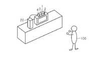
図1は、ゲームをプレイするプレイヤの様子を示す図である。図1に示すように、プレイヤ100は、例えば、位置検出装置1の前方に位置する。詳細は後述するが、位置検出装置1は、例えば、カメラや赤外線センサ等を含んで構成され、プレイヤ100の部位に対応する3次元座標を生成する。ゲーム装置20は、この3次元座標に基づいてゲームを実行する。プレイヤ100は、例えば、ゲーム画面に表示されたキャラクタのダンス及び楽曲に合わせてダンスをすることを目指す。[2. Game executed based on reference data]
FIG. 1 is a diagram illustrating a state of a player playing a game. As shown in FIG. 1, the
図2は、ゲーム画面の一例を示す図である。図2に示すように、ゲーム画面30には、楽曲に合わせてダンスを踊るキャラクタ32と、プレイヤの得点を示すスコア34とが含まれる。キャラクタ32は、例えば、ダンサーの踊りを撮影した映像にモーションキャプチャリング処理が施されて作成されたデータに基づいて表示される。 FIG. 2 is a diagram illustrating an example of a game screen. As shown in FIG. 2, the
例えば、ゲーム装置20がプレイヤの動作を判定する時間が近づくと、ゲーム画面30にマーク36が表示される。プレイヤは、このマーク36を頼りにゲームをプレイする。別の言い方をすれば、マーク36は、これからキャラクタ32が体を動かす位置及びタイミングをプレイヤに案内するための画像である。例えば、キャラクタ32の手がマーク36の中心に触れた場合に、プレイヤが同じ動作をしていると、プレイヤは高い評価を得ることになる。 For example, the
なお、本実施形態においては、ゲーム画面30に表示されるキャラクタ32とプレイヤが向き合った状態でゲームをプレイするため、ゲーム画面30においては、プレイヤがすべきダンスを左右反転させたダンスをキャラクタ32が踊るように、キャラクタ32が表示される。例えば、プレイヤから見て右側の手(キャラクタ32から見て左側の手)をキャラクタ32が上げた場合にプレイヤが右手を上げると、プレイヤは高い評価を得ることになる。 In the present embodiment, the game is played with the player facing the
このように、プレイヤは、キャラクタ32のダンスと同じようにダンスをすることを目指す。ゲーム装置20においては、設定者(例えば、プレイヤ又はゲーム制作者)が、キャラクタ32のダンスのうちプレイヤの動作及び当該動作を判定する時を設定し、基準データを生成する。設定者(以降、設定者がプレイヤである場合を説明する。)は、設定画面において基準データの生成を行う。 In this way, the player aims to dance in the same manner as the
図3は、設定画面の一例を示す図である。図3に示すように、設定画面70は、キャラクタ32を含む。キャラクタ32は、モーションデータに基づいて表示される。設定画面70におけるキャラクタ32は、ゲーム画面30(図2)におけるキャラクタ32と同様の動作をする。 FIG. 3 is a diagram illustrating an example of the setting screen. As shown in FIG. 3, the
また、設定画面70には、基準データに設定されている内容を示す設定指示画像72が表示される。プレイヤは、例えば、設定指示画像72の表示内容を頼りに基準データの設定及び生成を行う。本実施形態においては、プレイヤがゲームの設定を行う場合、楽曲及びキャラクタ32のダンスが同期再生される構成になっている。以降、この技術について詳細に説明する。 In addition, a setting
[3.位置検出装置の動作]
まず、位置検出装置1について説明する。位置検出装置1は、3次元空間におけるプレイヤの位置に関するプレイヤ位置情報を生成する。本実施形態においては、プレイヤの位置情報が、プレイヤ100の複数の部位の位置に関する情報を含む場合を説明する。プレイヤ100の部位は、例えば、頭や両腕等である。[3. Operation of position detection device]
First, the
図1に示すように、位置検出装置1は、例えば、CCDカメラ2、赤外線センサ3、複数のマイクロフォンを含むマイク4等を備える。 As shown in FIG. 1, the
CCDカメラ2は、CCDイメージセンサを備えた公知のカメラである。CCDカメラ2は、例えば、所定時間毎(例えば1/60秒毎)にプレイヤ100を撮影した撮影画像(例えば、RGBデジタル画像)を生成する。 The
図4は、CCDカメラ2によって生成される撮影画像の一例を示す図である。図4に示すように、撮影画像には、例えば、プレイヤ100が含まれる。撮影画像には、互いに直行するXs軸、Ys軸が設定される。例えば、撮影画像の左上を、原点Os(0,0)とする。また例えば、撮影画像の右下を、座標Pmax(Xmax,Ymax)とする。撮影画像に対応する各画素の位置は、それぞれの画素に割り当てられる2次元座標(Xs−Ys座標)によって特定される。 FIG. 4 is a diagram illustrating an example of a captured image generated by the
赤外線センサ3は、例えば、赤外線発光素子及び赤外線受光素子(例えば、赤外線ダイオード)から構成される。赤外線センサ3は、赤外線光を照射して得られる反射光を検出する。赤外線センサ3は、この反射光の検出結果に基づいて被写体(例えば、プレイヤ100)の深度を測定する。 The
被写体の深度とは、測定基準位置と被写体の位置との距離間隔である。測定基準位置とは、プレイヤ100の位置の深度(奥行き)を測定する際の基準となる位置である。測定基準位置は、位置検出装置1の位置と関連付けられる所定の位置であればよく、例えば、赤外線センサ3の赤外線受光素子の位置である。赤外線センサ3は、例えば、赤外線を照射してから反射光を受光するまでの飛行時間(TOF:Time of Flight)に基づいてプレイヤ100の深度を測定する。 The subject depth is a distance interval between the measurement reference position and the subject position. The measurement reference position is a position serving as a reference when measuring the depth (depth) of the position of the
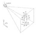
図5は、赤外線センサ3によるプレイヤ100の深度の測定方法を説明するための図である。図5に示すように、赤外線センサ3から所定間隔でパルス状の赤外線光が照射される。赤外線センサ3から照射された赤外線光は、赤外線センサ3の発光位置を中心点として球状に広がる。 FIG. 5 is a diagram for explaining a method of measuring the depth of the
赤外線センサ3から照射された赤外線光は、例えば、プレイヤ100の体の表面に当たる。これらの表面に当たった赤外線光は、反射する。反射した赤外線光は、赤外線センサ3の赤外線受光素子により検出される。即ち、赤外線センサ3は、照射した赤外線に対して位相が180度反転した反射光を検出する。 For example, the infrared light emitted from the
例えば、図5に示すように、プレイヤ100が両手を前方に突き出している場合、突き出された両手は、プレイヤ100の胴体よりも赤外線センサ3に近い。つまり、プレイヤ100の両手によって反射される赤外線光の飛行時間は、プレイヤ100の胴体によって反射される赤外線光の飛行時間よりも短い。 For example, as shown in FIG. 5, when the
赤外線センサ3が赤外線光を照射してから反射光を検出するまでの時間(つまり、飛行時間)と、赤外線の速度と、を乗算して半分で割った値は、測定基準位置とプレイヤ100との距離間隔(即ち、深度)に相当する。このような処理を行うことにより、赤外線センサ3は、プレイヤ100の深度を測定する。 The value obtained by multiplying the time from when the
また、赤外線センサ3は、反射した赤外線光から得られる深度差を検出することにより、被写体(プレイヤ100)の輪郭も検出する。上記のように、赤外線センサ3が赤外線光の反射光を受信することは、この場所に物体が配置されていることを意味する。また、この物体の後方の近い位置に他の物体が配置されていなければ、この物体と、この物体の周囲と、の深度差は大きくなる。例えば、深度差が所定値よりも大きい箇所をつなぎ合わせることによって、プレイヤ100の輪郭を検出する。 The
なお、プレイヤ100の輪郭を検出する方法は、上記の例に限られない。他にも例えば、CCDカメラ2によって得られる撮影画像の各画素の輝度に基づいて輪郭を検知するようにしてもよい。この場合も、例えば、画素間の輝度差が大きい箇所をつなぎ合わせることによってプレイヤ100の輪郭を検出することができる。 Note that the method of detecting the contour of the
上記のようにして検出されるプレイヤ100の深度に関する情報(深度情報)は、例えば、深度画像として表現される。本実施形態においては、深度情報が、グレースケールの深度画像(例えば、256ビットのグレースケールの画像データ)として表現される例を挙げて説明する。 Information (depth information) relating to the depth of the
図6は、赤外線センサ3によって得られる深度画像の一例を示す図である。図6に示すように、例えば、赤外線センサ3に近い物体は明るく(輝度が高く)、遠い物体は暗く(輝度が低く)表現される。プレイヤ100の深度は、深度画像の輝度(画素値)に対応する。 FIG. 6 is a diagram illustrating an example of a depth image obtained by the
例えば、深度画像が256ビットのグレースケールの画像データとして表される場合、プレイヤ100の深度が2センチメートル異なる毎に深度画像の輝度が1ビット異なる。この場合、赤外線センサ3は、被写体の深度を2センチ単位で検出することが可能であることを示す。プレイヤ100が両手を前方に突き出している場合(図5)、図6に示すように、プレイヤ100の両手に対応する画素は、胴体に対応する画素よりも明るく(輝度が高く)表現される。 For example, when the depth image is represented as 256-bit grayscale image data, the brightness of the depth image is different by 1 bit every time the depth of the
本実施形態においては、赤外線センサ3は、CCDカメラ2と同様に所定時間毎(例えば1/60秒毎)に、深度画像を生成する。CCDカメラ2により得られる撮影画像と、赤外線センサ3により得られる深度画像と、に基づいてプレイヤ100の部位の位置に関するプレイヤ位置情報が生成される。 In the present embodiment, the
例えば、CCDカメラ2により得られる撮影画像(RGBデータ)に、深度画像が示す深度情報(D:Depth)が合算された合成画像(RGBDデータ)が生成される。即ち、合成画像は、各画素ごとに、色情報(RGBそれぞれの明度)と深度情報とを含む。 For example, a composite image (RGBD data) in which depth information (D: Depth) indicated by the depth image is added to a captured image (RGB data) obtained by the
合成画像に基づいてプレイヤ位置情報が生成される際には、まず、深度画像に基づいてプレイヤ100の輪郭に対応する画素が特定される。次いで、合成画像のうち輪郭によって囲まれた画素の色情報(RGBの明度)が参照される。合成画像の色情報に基づいて、プレイヤ100の体の各部位に対応する画素が特定される。この特定方法としては、例えば、比較画像(教師画像)との比較によって画像の中から対象物(即ち、プレイヤ100の体の各部位)を抽出するパターンマッチング法等、公知の手法を適用可能である。 When the player position information is generated based on the composite image, first, pixels corresponding to the contour of the
上記のようにして特定された画素の画素値(RGBD値)に基づいて、プレイヤ100の頭や肩等の3次元座標が算出される。例えば、この画素値に対して所定の行列変換処理が施されることによって、3次元座標が生成される。この行例変換処理は、例えば、3Dグラフィックにおけるワールド座標−スクリーン座標の2つの座標系の変換処理と同様の行例演算によって実行される。つまり、画素の色情報を示すRGB値と奥行きを示すD値と、が所定の行列式に代入されることにより、この画素の3次元座標が算出される。 Based on the pixel values (RGBD values) of the pixels specified as described above, three-dimensional coordinates such as the head and shoulders of the
なお、画素値(RGBD値)から画素に対応する3次元座標が算出される方法は、公知の手法を適用可能であり、この算出方法は、上記の例に限られない。他にも例えば、ルックアップテーブルを用いて座標変換が行われるようにしてもよい。 A known method can be applied to the method for calculating the three-dimensional coordinates corresponding to the pixel from the pixel value (RGBD value), and this calculation method is not limited to the above example. In addition, for example, coordinate conversion may be performed using a lookup table.
図7は、位置検出装置1により生成されるプレイヤ位置情報の一例を示す図である。図7に示すように、プレイヤ位置情報は、プレイヤ100の複数の部位の位置に関する複数の情報を含む。プレイヤ位置情報は、例えば、プレイヤ100の各部位と、3次元座標と、が対応付けられて格納される。 FIG. 7 is a diagram illustrating an example of player position information generated by the
図8は、プレイヤ位置情報によって特定されるプレイヤ100の位置を示す図である。本実施形態では、例えば、位置検出装置1に対応する所定位置(例えば、測定基準位置)を原点Opとする。例えば、原点Opは、赤外線センサ3の測定基準位置に対応する3次元座標である。なお、原点Opの位置は、プレイヤ100がいる3次元空間のどこに設定されてもよい。例えば、撮影画像の原点Osに対応する3次元座標が、原点Opとして設定されるようにしてもよい。 FIG. 8 is a diagram illustrating the position of the
図8に示すように、本実施形態では、プレイヤ位置情報がプレイヤ100の複数の部位のうちで少なくとも頭の位置及び腰の位置に関する部位情報を含む場合を説明する。例えば、プレイヤ位置情報は、プレイヤ100の頭P1、肩P2、左上腕P3、右上腕P4、左下腕P5、右下腕P6、背中P7、左ももP8、右ももP9、左すねP10、右すねP11に対応する11個の3次元座標が含まれる。 As shown in FIG. 8, in the present embodiment, a case will be described in which the player position information includes at least part information related to the position of the head and the position of the waist among the plurality of parts of the
なお、プレイヤ位置情報によって示されるプレイヤ100の体の部位は、プレイヤの体(骨格)のうちで予め定められた部位のものであってよい。例えば、この部位は、先述したパターンマッチング法によって特定可能な体の部位であればどこでもよい。 Note that the body part of the
例えば、所定間隔毎(例えば、1/60秒毎)に生成されるプレイヤ位置情報は、位置検出装置1からゲーム装置20に対して送信される。ゲーム装置20は、プレイヤ位置情報を位置検出装置1から受信し、プレイヤ(以降、プレイヤの「100」の符号を省略する。)の体の動きを把握してゲームを実行する。 For example, player position information generated at predetermined intervals (for example, every 1/60 seconds) is transmitted from the
次に、位置検出装置1とゲーム装置20とのハードウェア構成について説明する。 Next, the hardware configuration of the
[4.位置検出装置の構成]
図9は、位置検出装置1のハードウェア構成を示す図である。図9に示すように、位置検出装置1は、制御部10、記憶部11、撮影部12、深度測定部13、音声入力部14、通信インタフェース部15から構成される。位置検出装置1の各構成要素は、バス16によってデータ送受信可能に接続される。[4. Configuration of position detection device]
FIG. 9 is a diagram illustrating a hardware configuration of the
制御部10は、記憶部11に記憶されるオペレーティングシステム、各種プログラムに基づいて位置検出装置1の各部を制御する。 The
記憶部11は、オペレーティングシステムや撮影部12、深度測定部13を動作させるためのプログラム、各種パラメータを記憶する。また、記憶部11は、撮影画像及び深度画像に基づいてプレイヤ位置情報を生成するためのプログラムを記憶する。 The
撮影部12は、CCDカメラ2等から構成される。撮影部12は、例えば、プレイヤの撮影画像を生成する。深度測定部13は、赤外線センサ3等から構成される。深度測定部13は、例えば、赤外線センサ3により得られる飛行時間に基づいて深度画像を生成する。制御部10は、先述のように、所定時間毎(例えば、1/60秒毎)に、撮影部12により生成される撮影画像と、深度測定部13により生成される深度画像と、に基づいて、プレイヤ位置情報を生成する。 The photographing
音声入力部14は、マイク4等から構成される。通信インタフェース部15は、ゲーム装置20に対してプレイヤ位置情報等の各種データを送信するためのインタフェースである。 The
[5.ゲーム装置の構成]
図10は、ゲーム装置20のハードウェア構成を示す図である。図10に示すように、ゲーム装置20は、制御部21、主記憶部22、補助記憶部23、光ディスク再生部24、通信インタフェース部25、操作部26、表示部27、及び音声出力部28を含む。ゲーム装置20の各部はバス29によって接続されている。[5. Configuration of game device]
FIG. 10 is a diagram illustrating a hardware configuration of the
制御部21は、例えばCPU、GPU(Graphics Processing Unit)、及びSPU(Sound Processing Unit)等を含む。制御部21は、オペレーティングシステムやその他のプログラムに従って各種処理を実行する。 The
主記憶部22は、例えば、RAM(Random Access Memory)を含む。補助記憶部23は、例えば、ハードディスク装置(情報記億媒体)を含む。主記憶部22は、補助記憶部23又は光ディスク(情報記憶媒体)から読み出されたプログラムやデータを記憶する。また、主記憶部22は、処理の過程で必要なデータを記憶するワークメモリとしても用いられる。 The
光ディスク再生部24は、光ディスクに記憶されたプログラムやデータを読み取る。光ディスクには、例えば、ゲームプログラムが記憶されている。 The optical
通信インタフェース部25は、ゲーム装置20を通信ネットワークに通信接続するためのインタフェースである。 The
操作部26は、プレイヤが操作を行うためのものである。操作部26は、例えば、十字キーや各種ボタンを含むゲームコントローラ、タッチパネル、マウス、又はキーボード等を含む。表示部27は、例えば、家庭用テレビ受像機又は液晶表示パネル等である。表示部27は、例えば、基準データを生成するための設定画面70を表示する。音声出力部28は、例えば、スピーカ又はヘッドホン等を含む。 The
本実施形態においては、ゲームの実行に際して必要なプログラムやデータは、光ディスクを介してゲーム装置20に供給される場合を説明する。なお、これらのプログラムやデータは、他の情報記憶媒体(例えば、メモリカード)を介してゲーム装置20に供給されるようにしてもよい。または、プログラムやデータは、通信ネットワークを介して遠隔地からゲーム装置20に供給されるようにしてもよい。 In the present embodiment, a case will be described in which a program and data necessary for executing a game are supplied to the
[6.ゲーム装置で実現される機能]
図11は、ゲーム装置20において実現される機能を示す機能ブロック図である。図11に示すように、ゲーム装置20では、ゲームデータ記憶部40、見本データ取得部42、指定受付部44、表示制御部46、基準データ生成部48が実現される。これらの機能は、制御部21が、光ディスクから読み出されたプログラムに従って動作することにより、実現される。[6. Functions realized with game devices]
FIG. 11 is a functional block diagram showing functions implemented in the
[6−1.ゲームデータ記憶部]
ゲームデータ記憶部40は、主記憶部22及び補助記憶部23を主として実現される。ゲームデータ記憶部40は、ゲームを実行するために必要な情報を記憶する。例えば、ゲームデータ記憶部40には、以下のようなデータが格納される。
(1)楽曲データ(一般のポピュラー音楽等を所定のデータ形式で保存したデータ)
(2)モーションデータ
(3)基準データ
(4)プレイヤ位置情報を時系列的に格納したデータ
(5)ゲーム状況データ(実行中のゲームの状況(得点や経過時間等)を示すデータ)[6-1. Game data storage unit]
The game
(1) Music data (data storing general popular music etc. in a predetermined data format)
(2) Motion data (3) Reference data (4) Data storing player position information in time series (5) Game status data (data indicating the status of the game being executed (scores, elapsed time, etc.))
なお、上記のデータのうち、楽曲データ、モーションデータ、及び基準データは、予めゲーム作成者によって用意されたデータである。プレイヤ位置情報は、位置検出装置1から取得されるデータであり、ゲーム状況データは、ゲームプログラムによって生成及び更新されるデータである。また、制御部21は、ゲームデータ記憶部40に格納された各種データを取得する手段として機能する。 Of the above data, music data, motion data, and reference data are data prepared in advance by the game creator. The player position information is data acquired from the
[モーションデータ]
まず、モーションデータについて説明する。モーションデータは、例えば、ダンサーの動きを撮影した映像にモーションキャプチャリング処理を施して生成されるデータに基づいて、ゲーム製作者によって作成される。モーションデータは、例えば、キャラクタ32の各部位の位置を特定するためのデータである。[Motion data]
First, motion data will be described. For example, the motion data is created by a game creator based on data generated by performing a motion capturing process on a video of a dancer's motion. The motion data is data for specifying the position of each part of the
本実施形態においては、モーションデータには、楽曲の再生が開始されてからの経過時間(例えば、1/256小節毎)と、ゲーム空間におけるキャラクタ32の各部位(骨格)を示すデータと、が対応付けられて格納される場合を説明する。 In the present embodiment, the motion data includes an elapsed time (for example, every 1/256 measure) after the music playback is started, and data indicating each part (skeleton) of the
即ち、モーションデータには、キャラクタ32の姿勢を示すデータが時系列的に格納される。ゲーム装置20は、モーションデータに基づいて、キャラクタ32を示すオブジェクトをゲーム空間に配置することによって、ゲーム画面30においてキャラクタ32がダンスを踊るように表示制御を行うことができる。 That is, the motion data stores data indicating the posture of the
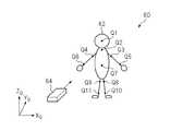
図12は、ゲーム空間を示す図である。図12に示すように、ゲーム空間60には、キャラクタ32を示すキャラクタオブジェクト62と、仮想カメラ64(視点)と、が配置される。キャラクタオブジェクト62は、複数のポリゴンを含んで構成される。例えば、モーションデータに格納されたキャラクタ32の部位を示すデータに基づいてキャラクタオブジェクト62が作成される。 FIG. 12 shows a game space. As shown in FIG. 12, a
キャラクタオブジェクト62は、プレイヤが取るべき姿勢を案内するように変化する。本実施形態においては、キャラクタ32が、プレイヤがすべきダンスを左右反転させたダンスを踊る場合を説明する。例えば、プレイヤが右手を上方に位置させるべき場合には、キャラクタオブジェクト62のうちキャラクタ32の左手を示すオブジェクトが上方に位置する。即ち、モーションデータには、キャラクタ32が、プレイヤがすべきダンスを左右反転させたダンスを踊るように、キャラクタ32の部位の位置が定義されている。 The character object 62 changes so as to guide the posture that the player should take. In the present embodiment, a case will be described in which the
ゲーム画面30には、ゲーム空間60を仮想カメラ64から見た様子を示す画像が表示される。仮想カメラ64の位置や視線方向を示す情報は、固定値であってもよいし、ゲームプログラムやプレイヤの操作に基づいて変動するようにしてもよい。仮想カメラ64の位置や視線方向を示す情報は、例えば、ゲーム状況データに格納される。また、モーションデータと楽曲データとは、キャラクタ32が楽曲に合わせてダンスを踊るように同期再生される。 On the
[基準データ]
次に、基準データについて説明する。基準データは、楽曲データの再生時間内に設定される基準時点に関する情報と、基準時点においてプレイヤの部位があるべき基準位置に関する情報と、を対応付けてなるデータである。基準時点とは、ゲーム装置20がプレイヤの動作を判定(評価)すべき時点である。基準データに基づいて、楽曲データの再生期間内に行われるプレイヤの動作が評価される。楽曲データの再生期間内とは、楽曲の始点から終点までの期間内のことである。[Reference data]
Next, reference data will be described. The reference data is data obtained by associating information on the reference time set within the reproduction time of the music data with information on the reference position where the player's part should be at the reference time. The reference time point is a time point at which the
本実施形態においては、基準データは、判定用位置データと設定データとを含んでいる場合を説明する。判定用位置データは、楽曲の再生が開始されてからの各時点においてプレイヤの各部位があるべき位置を示すデータである。例えば、楽曲の再生が開始されてからの経過時間と、この経過時間においてプレイヤの部位があるべき位置(3次元座標)と、が対応付けられて判定用位置データに格納される。モーションデータと同様に、判定用位置も、ダンサーの動きを撮影した映像にモーションキャプチャリング処理を施して生成されるデータに基づいて、ゲーム製作者によって作成される。判定用位置データは、プレイヤ位置情報が示すプレイヤの部位の位置と比較される。 In the present embodiment, a case will be described in which the reference data includes determination position data and setting data. The position data for determination is data indicating the position where each part of the player should be at each time point after the reproduction of the music is started. For example, the elapsed time from the start of music playback and the position (three-dimensional coordinates) where the player's part should be located in this elapsed time are associated with each other and stored in the determination position data. Similar to the motion data, the determination position is also created by the game creator based on data generated by performing a motion capturing process on the video of the dancer's motion. The position data for determination is compared with the position of the part of the player indicated by the player position information.
また、本実施形態においては、判定用位置データが、プレイヤに設定される代表点に基づいた座標系で表現される場合を説明する。例えば、判定用位置データに格納される3次元座標は、代表点を原点とした座標系によって表現される。即ち、判定用位置データに格納されるプレイヤの各部位の位置座標は、プレイヤの各部位があるべき位置と、代表点の位置と、の位置関係を示している。 Further, in the present embodiment, a case will be described in which the position data for determination is expressed in a coordinate system based on representative points set for the player. For example, the three-dimensional coordinates stored in the determination position data are expressed by a coordinate system with the representative point as the origin. That is, the position coordinates of each part of the player stored in the position data for determination indicate the positional relationship between the position where each part of the player should be and the position of the representative point.
なお、本実施形態においては、代表点を背中P7とする。この場合、背中P7を原点とし、背中P7からの相対的な位置を示す3次元座標が、判定用位置データに格納される。プレイヤの動作が評価される場合には、ゲーム装置20は、プレイヤ位置情報を代表点に基づいた座標系で表現する。例えば、判定用位置データは、背中P7を原点とする座標系で表現されているので、プレイヤ位置情報に含まれる3次元座標も、背中P7を原点とする座標系で表現する。 In the present embodiment, the representative point is the back P7. In this case, the three-dimensional coordinates indicating the relative position from the back P7 with the back P7 as the origin are stored in the determination position data. When the action of the player is evaluated, the
なお、本実施形態においては、代表点が背中P7である場合を説明するが、代表点は、プレイヤ及びキャラクタ32に設定される点であればよく、背中P7でなくともよい。例えば、代表点は、頭P1等であってもよい。 In this embodiment, the case where the representative point is the back P7 will be described. However, the representative point may be a point set to the player and the
また、本実施形態においては、キャラクタ32は、プレイヤがすべきダンスの左右反対のダンスを踊るので、判定用位置データが示すプレイヤの頭P1、肩P2、左上腕P3、右上腕P4、左下腕P5、右下腕P6、背中P7、左ももP8、右ももP9、左すねP10、右すねP11の位置と、図12に示すキャラクタ32の頭Q1、肩Q2、左上腕Q3、右上腕Q4、左下腕Q5、右下腕Q6、背中Q7、左ももQ8、右ももQ9、左すねQ10、右すねQ11の位置と、は一定の関係(左右反対の関係)を保っている。 In the present embodiment, the
次に、設定データについて説明する。設定データは、基準時点と、当該基準時点においてゲーム装置20が判定するプレイヤの部位を特定するためのデータである。本実施形態においては、プレイヤは、設定画面70において、設定データの内容を設定することによって、基準データを生成する。 Next, setting data will be described. The setting data is data for specifying the reference time point and the part of the player determined by the
図13は、設定データの一例を示す図である。図13に示すt軸は、時間軸である。t軸は、楽曲の再生が開始されてからの経過時間を示している。例えば、設定データは、所定小節(例えば、1/16小節)毎に、ゲーム装置20が判定すべきプレイヤの部位を示している。本実施形態においては、設定データにおいて、頭、左手(例えば、左下腕)、右手(例えば、右下腕)、左足(例えば、左すね)、右足(例えば、右すね)の5つの部位が定義される場合を説明する。 FIG. 13 is a diagram illustrating an example of setting data. The t axis shown in FIG. 13 is a time axis. The t-axis indicates the elapsed time from the start of music playback. For example, the setting data indicates a part of the player to be determined by the
図13に示すように、1/16小節の各時点において、ゲーム装置20がプレイヤのダンスを判定すべきか否かは、「0」〜「7」の数値によって表されている。設定データに格納される「頭」、「左手」、「右手」、「左足」、「右足」の値は、それぞれ、ゲーム装置20がプレイヤの頭、左手、右手、左足、右足の位置を判定すべきか否かを示している。また、設定データの値の数値によって、ゲーム装置20がプレイヤの動作を判定する方法の種別が異なる。 As shown in FIG. 13, whether or not the
図14は、判定方法の種別を示す図である。図14に示すように、本実施形態においては、設定データに格納される値によって、ゲーム装置20がプレイヤの動作を判定する方法の種別が異なる。設定データに格納される値が「0」であることは、ゲーム装置20がプレイヤの動作を判定すべき時点ではないことを示している。即ち、設定データに格納される全ての部位が「0」である場合は、基準時点ではないことを示している。 FIG. 14 is a diagram illustrating types of determination methods. As shown in FIG. 14, in this embodiment, the type of method by which the
設定データに格納される部位の値が「1」〜「7」の何れかである場合、ゲーム装置20が判定すべきプレイヤの部位があることを示している。以降、この部位を判定対象部位という。即ち、設定データが「1」〜「7」である時間は、基準時点であることを示している。本実施形態においては、図14に示すように、ゲーム装置20がプレイヤの動作を判定する方法が、以下の7種類に分類される。
(1)Ripple:ゲーム装置20が、プレイヤがキャラクタ32と同じ手の動きをしているか否かを判定する。
(2)Step:ゲーム装置20が、プレイヤがキャラクタ32と同じ足の動きをしているか否かを判定する。
(3)Pose:ゲーム装置20が、プレイヤが全身を使ってキャラクタ32と同じポーズをしているか否かを判定する。
(4)Lock:ゲーム装置20が、プレイヤが、一定時間、キャラクタ32と同じ位置に部位を固定しているか否かを判定する。
(5)Solid:ゲーム装置20が、プレイヤが、一定時間、キャラクタ32と同じように手を振っているか否かを判定する。
(6)Stream:ゲーム装置20が、プレイヤが、一定時間、キャラクタ32と同じ手の動きをしているか否かを判定する。
(7)Gesture:ゲーム装置20が、プレイヤが、一定時間、全身又は一部の部位を使ってキャラクタ32と同じポーズをしているか否かを判定する。When the value of the part stored in the setting data is any one of “1” to “7”, it indicates that there is a part of the player to be determined by the
(1) Ripple: The
(2) Step: The
(3) Pose: The
(4) Lock: The
(5) Solid: The
(6) Stream: The
(7) Gesture: The
例えば、設定データの値が「1」、「2」、「4」、「5」、「6」の部位がある場合、ゲーム装置20は、これらの値になっているプレイヤの部位(頭、左手、右手、左足、右足)の動作を、上記の種別に基づいて判定する。また例えば、設定データの値が「3」、「7」の部位がある場合、ゲーム装置20は、プレイヤの全身又は一部の部位の動作を、上記種別に基づいて判定する。 For example, if there are parts whose setting data values are “1”, “2”, “4”, “5”, “6”, the
なお、本実施形態においては、プレイヤによって上記のような動作が行われる場合を説明するが、ゲーム装置20の判定方法の種別は、キャラクタ32のダンスに基づいた動作であればよく、ゲーム装置20の判定方法の種別は、上記の例に限られない。 In the present embodiment, the case where the player performs the above-described operation will be described. However, the type of determination method of the
[6−2.見本データ取得部]
見本データ取得部42は、制御部21を主として実現される。見本データ取得部42は、楽曲データの再生期間内の各時点におけるプレイヤの見本姿勢に関する見本データを記憶する手段から見本データを取得する。見本姿勢は、プレイヤがすべき動作(姿勢)を示すものであり、例えば、キャラクタ32の姿勢(ダンス)である。本実施形態においては、見本データ取得部42は、ゲームデータ記憶部40に記憶されたモーションデータを取得する。[6-2. Sample data acquisition section]
The sample
[6−3.指定受付部]
指定受付部44は、制御部21及び操作部26を主として実現される。指定受付部44は、設定画面70において、楽曲データの再生期間内における時点の指定を受け付ける。指定受付部44は、設定画面70の表示内容に基づいて、楽曲データの再生期間内における時点(経過時間)の指定をプレイヤから受け付ける。[6-3. Designated reception desk]
The
[6−4.表示制御部]
表示制御部46は、制御部21を主として実現される。表示制御部46は、指定された時点におけるプレイヤの見本姿勢を案内する見本画像(例えば、キャラクタ32)を、見本データ(例えば、モーションデータ)に基づいて設定画面70に表示させる。[6-4. Display control unit]
The
本実施形態においては、表示制御部46は、楽曲データが再生中の場合、設定画面70において見本画像(例えば、キャラクタ32)によって案内される見本姿勢を楽曲データの再生と同期するようにして変化させる。つまり、表示制御部46は、モーションデータが示す経過時間と、楽曲データが示す経過時間と、が一致するようにしてモーションデータが示すキャラクタ32を設定画面70に表示させる。 In the present embodiment, when the music data is being reproduced, the
表示制御部46により表示される設定画面70は、図3に示すように、キャラクタ32を含む。先述のように、キャラクタ32は、モーションデータに基づいて表示される。設定画面70におけるキャラクタ32は、ゲーム画面30(図2)におけるキャラクタ32と同様の動作をする。 The
また、設定画面70には、設定データの内容を示す設定指示画像72が表示される。設定指示画像72は、プレイヤが設定データの設定を行うためのものである。例えば、現在設定されている設定データの内容に基づいて設定指示画像72が表示される。 In addition, a setting
図3に示すように、設定指示画像72には、設定データに格納される基準時点及び当該基準時点において判定に用いられる部位が対応づけられて表示される。例えば、設定指示画像72には2軸が設定され、一方の軸(例えば、縦軸)には、楽曲データの再生時間内の時点が関連付けられ、他方の軸(例えば、横軸)には、ゲーム装置20が判定すべきプレイヤの部位が関連付けられている。 As shown in FIG. 3, the setting
図15は、設定データと設定指示画像72との関係を示す図である。図15に示すように、設定データに基づいて設定指示画像72の表示内容が決定される。例えば、現在の経過時間を含む所定時間内の設定データに基づいて設定指示画像72が表示される。設定データに格納される判定方法の種別は、四角や丸等のアイコンによって区別されて設定指示画像72に表示される。 FIG. 15 is a diagram showing the relationship between the setting data and the setting
なお、StreamやSolidのように一定期間にわたって行われる判定については、図15に示すように、アイコン同士がつながって表示されるようにしてもよい。また、表示制御部46は、楽曲データの再生期間の時間軸tを設定指示画像72に表示させる。図15に示す例では、設定指示画像72に設定される横軸が、時間軸tに対応する。 In addition, about the determination performed over a fixed period like Stream and Solid, as shown in FIG. 15, you may make it display icons connected. Further, the
設定画面70が表示されると、楽曲データの再生の時間経過に伴い、設定指示画像72の表示が更新される。例えば、楽曲データの再生の時間経過に伴って設定指示画像72が時間軸tに対応する方向(例えば、左方向)にスクロールする。このように設定指示画像72が表示されることによって、プレイヤは、実際にゲームをプレイした場合に、現在の経過時間において、どのような種別の判定がなされるかを把握しながら設定作業を行うことができる。 When the
また、本実施形態においては、表示制御部46は、プレイヤの複数の部位に対応する複数の領域72a〜72eを、設定画面70に表示された時間軸tの方向に延伸するように、かつ、時間軸tに直交する方向に並列に設定する。例えば、領域72a〜72eの長手方向は、時間軸tの方向となる。複数の領域72a〜72eは、各領域72a〜72eの短手方向に並列に配置される。 In the present embodiment, the
例えば、設定指示画像72に設定される複数の領域72a〜72eのそれぞれは、判定対象部位に対応する。本実施形態においては、判定対象部位が頭、左手、右手、左足、右足の5つであるので、図15に示すように、これら5つの部位に対応する5つの領域72a〜72eが設定される。 For example, each of the plurality of regions 72a to 72e set in the setting
図3に戻り、設定指示画像72は、基準時点指示画像74と、基準位置指示画像76と、を更に含む。プレイヤは、基準時点指示画像74に基づいて基準時点の設定を行い、基準位置指示画像76に基づいて基準位置の設定を行う。 Returning to FIG. 3, the setting
基準時点指示画像74は、設定指示画像72に表示された時間軸tが示す再生期間内の時点をプレイヤが指定するためのものである。基準時点指示画像74は、プレイヤの操作に基づいて左右に移動する。プレイヤが基準時点指示画像74を移動させると、プレイヤは、楽曲データの再生期間内の時点を指定及び変更することができる。 The reference time
即ち、指定受付部44は、設定画面70に表示された時間軸tに基づいて、楽曲データの再生期間内の時点の指定を受け付ける。本実施形態においては、時間軸tは、楽曲の所定拍毎に楽曲データの再生期間を示しているので、指定受付部44は、楽曲の所定拍毎に楽曲データの再生期間内における時点の指定を受け付ける。 That is, the
表示制御部46は、プレイヤによって指定された時点におけるキャラクタ32の動作を設定画面70に表示させる。例えば、プレイヤが基準時点指示画像74を移動させることによって指示した時点と、モーションデータと、に基づいて、この時点におけるキャラクタ32の動作(姿勢)が設定画面70に表示される。 The
また、基準位置指示画像76は、設定画面70に設定された複数の領域72a〜72eの何れかの位置を、プレイヤが指定するためのものである。基準位置指示画像76は、プレイヤの操作に基づいて上下に移動する。プレイヤは、基準位置指示画像76を移動させることによって判定対象部位を指定し、基準位置を設定することができる。即ち、指定受付部44は、設定画面70に設定された複数の領域72a〜72eの何れかの位置の指定を受け付ける。 The reference
なお、図3に示すように、設定画面70においては、ゲーム装置20の判定方法の種別毎に、基準時点の数が判定方法表示欄78に表示されるようにしてもよい。判定方法表示欄78の表示内容は、設定データが示す「1」〜「7」の数値に基づいて決定される。 As shown in FIG. 3, on the
また、判定方法表示欄78は、プレイヤが設定すべき判定方法の種別を示すカーソル80を含む。プレイヤが所定の操作を行うことによって、カーソル80が上下に移動する。カーソル80が上下に移動することによって、プレイヤが設定する判定方法の種別を変更することができるようにしている。 The determination
[6−5.基準データ生成部]
基準データ生成部48は、制御部21を主として実現される。基準データ生成部48は、設定画面70において指定された時点と、この指定された時点のプレイヤの見本姿勢における部位の位置と、に基づいて基準データを生成する。例えば、基準データ生成部48は、指定受付部44が受け付けた時点に基づいて基準時点を設定し、この時点の見本動作(例えば、キャラクタ32の動作)に基づいて基準位置を設定する。[6-5. Reference data generator]
The reference
また、本実施形態においては、基準データ生成部48は、設定画面70において指定された領域72a〜72eの位置に対応する時点と、この指定された領域72a〜72eの位置に対応する部位の位置と、に基づいて前記基準データを生成する場合を説明する。例えば、基準データ生成部48は、基準位置指示画像76が示す部位及びカーソル80が示す判定方法の種別に基づいて、設定データの設定内容を特定することになる。 Further, in the present embodiment, the reference
例えば、図3の状態の場合、プレイヤが所定の設定指示操作を行うと、楽曲データの再生が開始されてから「2と3/4」小節目に、プレイヤの左手にRippleの判定が行われるように、設定データを設定することができる。基準位置は、判定用位置データに格納された「2と3/4」小節目の左下腕P5の3次元座標となる。 For example, in the state of FIG. 3, when the player performs a predetermined setting instruction operation, Ripple determination is performed on the player's left hand in the “2 and 3/4” measures after the music data reproduction is started. In this way, setting data can be set. The reference position is the three-dimensional coordinate of the lower left arm P5 of the “2 and 3/4” bar stored in the determination position data.
即ち、基準データ生成部48は、基準時点指示画像74に基づいて指定される時点と、基準位置指示画像76に基づいて指定されるキャラクタ32の部位及びカーソル80で指定される判定方法の種別と、に基づいて設定データを生成することによって、基準データを生成する。 That is, the reference
設定指示操作が行われると、設定指示画像72及び判定方法表示欄78の表示内容も更新される。また、プレイヤが設定指示操作を行った場合、基準時点指示画像74及び基準位置指示画像76が示す設定指示画像72内の位置に、設定された判定方法の種別を示すアイコンが表示される。 When the setting instruction operation is performed, the display contents of the setting
[7.ゲーム装置において実行される処理]
図16は、ゲーム装置20において実行される処理の一例を示すフロー図である。図16の処理は、例えば、設定画面70が表示される場合に、制御部21が、光ディスクから読み出されたプログラムに従って動作することにより実行される。[7. Processing executed in game device]
FIG. 16 is a flowchart showing an example of processing executed in the
まず、図16に示すように、制御部21は、楽曲データに基づいて楽曲を再生する(S101)。制御部21は、モーションデータに基づいてキャラクタ32のダンスを開始させ、設定画面70を表示させる(S102)。S102においては、モーションデータに基づいてゲーム空間60にキャラクタオブジェクト62が配置される。そして、仮想カメラ64からゲーム空間60を見た様子を示す画像が、設定画面70に表示される。なお、S101及びS102に処理によって、楽曲に合わせてキャラクタ32がダンス(プレイヤがすべきダンスとは左右反対のダンス)をするように、楽曲データとモーションデータとは同期再生される。 First, as shown in FIG. 16, the
制御部21は、現在の楽曲の経過時間に基づいて設定画面70の表示内容を更新し、楽曲データとモーションデータとの同期再生を行う(S103)。S103においては、例えば、経過時間の経過に伴って、キャラクタ32が楽曲に合わせてダンスを行い、設定指示画像72が時間軸tの方向にスクロールする。 The
制御部21は、再生停止操作が行われたか否かを判定する(S104)。S104においては、操作部26の所定ボタンが押下されたか否かに基づいて、再生停止操作が行われたか否か判定される。 The
再生停止操作が行われた場合(S104;Y)、制御部21は、楽曲の再生を停止する(S105)。制御部21は、モーションデータの同期再生を停止する(S106)。つまり、制御部21(表示制御部46)は、楽曲データの再生が停止された場合、楽曲データの再生が停止された時点における見本画像(例えば、キャラクタ32)を設定画面70に表示させる。S105において楽曲の再生が停止するので、設定画面70において、キャラクタ32のダンスが停止し、設定指示画像72のスクロールも停止する。 When the reproduction stop operation is performed (S104; Y), the
制御部21は、基準時点指示画像74の移動指示(時点指定操作)が行われたか否かを判定する(S107)。例えば、操作部26の十字キーの左右のボタンが押下されたか否かが判定される。 The
基準時点指示画像74の移動指示が行われた場合(S107;Y)、制御部21は、この移動指示に基づいて基準時点指示画像74を移動させて、楽曲データの経過時間を変更させる(S108)。 When the movement instruction of the reference
S108においては、制御部21(指定受付部44)は、所定の時点指定操作に基づいて、楽曲データの再生が停止された時点よりも前の時点、又は、楽曲データの再生が停止された時点よりも後の時点を、指定された時点として取得する。楽曲データの再生が停止された時点とは、再生停止操作が行われた場合の楽曲の経過時間のことである。即ち、S108においては、基準時点指示画像74の移動に伴って、現在の経過時間が変更される。例えば、基準時点指示画像74が左に移動した場合、経過時間が戻り、基準時点指示画像74が右に移動した場合、経過時間が先に進む。 In S <b> 108, the control unit 21 (designation receiving unit 44), based on a predetermined time point designation operation, a time point before the time point when the reproduction of the music data is stopped or a time point when the reproduction of the music data is stopped The later time is acquired as the specified time. The point in time when the reproduction of the music data is stopped is the elapsed time of the music when the reproduction stop operation is performed. That is, in S108, the current elapsed time is changed as the reference time
制御部21は、変更された経過時間に基づいてキャラクタ32の表示を更新する(S109)。現在の経過時間が変更されると、S109において、モーションデータに基づいてキャラクタ32の表示が更新される。本実施形態においては、図3及び図15に示すように、時間軸tは、楽曲の所定拍毎に経過時間を示しているので、S109においては、この所定拍毎に指定された経過時間におけるキャラクタ32の動作が、設定画面70に表示される。また、後述するS113において、この所定拍毎に指定された経過時間に基づいて基準時点が設定される。 The
一方、基準時点指示画像74の移動指示が行われない場合(S107;N)、制御部21は、基準位置指示画像76の移動指示が行われたか否かを判定する(S110)。例えば、操作部26の十字キーの上下のボタンが押下されたか否かが判定される。 On the other hand, when the movement instruction of the reference
基準位置指示画像76の移動指示が行われた場合(S110;Y)、制御部21は、基準位置指示画像76を移動させる(S111)。例えば、基準位置指示画像76は、操作部26から入力される操作に基づいて上下に移動する。 When an instruction to move the reference
基準位置指示画像76の移動指示が行われない場合(S110;N)、制御部21は、設定指示操作が行われたか否かを判定する(S112)。設定指示操作が行われた場合(S112;Y)、制御部21は、基準時点指示画像74に基づいて基準時点を設定し、基準位置指示画像76が示す部位に基づいて基準位置を設定する(S113)。即ち、S113においては、設定データの内容が設定されることによって、基準データが生成される。なお、カーソル80の位置は、適宜、プレイヤが入力する所定の操作によって上下に移動するようにしてもよい。 When the movement instruction of the reference
設定指示操作が行われない場合(S112;N)、制御部21は、設定内容確認操作が入力されたか否かを判定する(S114)。設定内容確認操作は、予め定められた操作であればよい。例えば、設定内容確認操作は、操作部26の所定のボタンが押下されることであってもよい。 When the setting instruction operation is not performed (S112; N), the
設定内容確認操作が入力された場合(S114;Y)、処理はS103に戻り、モーションデータ及び楽曲データの同期再生が再開される。つまり、制御部21は、基準データが生成された後、設定画面70において所定の設定内容確認操作が行われた場合、楽曲データを再生する。 When the setting content confirmation operation is input (S114; Y), the process returns to S103, and the synchronized playback of motion data and music data is resumed. That is, after the reference data is generated, the
また、楽曲データの再生に同期してモーションデータが再生される。即ち、基準データが生成された後、設定内容確認操作が行われた場合、楽曲データの再生と同期して、設定画面70において見本画像(例えば、キャラクタ32)によって案内される見本姿勢が変化する。例えば、楽曲の時間経過に伴い、モーションデータに基づいてキャラクタ32の表示処理が行われる。 In addition, the motion data is reproduced in synchronization with the reproduction of the music data. That is, when the setting content confirmation operation is performed after the reference data is generated, the sample posture guided by the sample image (for example, the character 32) on the
更に、楽曲データの再生と同期して、基準時点及び基準位置が基準データに基づいて案内されるようにしてもよい。例えば、基準時点及び基準位置が、音声又は画像によって案内される。例えば、基準時点が訪れる場合、基準位置を案内する音声が音声出力部28から出力されるようにしてもよいし、基準位置を案内するマーク36が設定画面70に表示されるようにしてもよい。これらの音声データ又は画像データは、予めゲームデータ記憶部40に記憶されるようにしてもよい。 Furthermore, the reference time point and the reference position may be guided based on the reference data in synchronization with the reproduction of the music data. For example, the reference time point and the reference position are guided by sound or an image. For example, when the reference time point comes, a sound for guiding the reference position may be output from the
設定内容確認操作が入力されない場合(S114;N)、制御部21は、終了条件を満たすか否かを判定する(S115)。終了条件は、予め定められた条件であればよい。例えば、終了条件は、プレイヤによって基準データの設定を終了する旨の指示が入力されたか否かであってもよい。 When the setting content confirmation operation is not input (S114; N), the
終了条件を満たす場合(S115;Y)、処理は終了する。終了条件を満たさない場合(S115;N)、処理はS104に戻り、設定画面70からの基準データの設定が継続される。 If the end condition is satisfied (S115; Y), the process ends. If the end condition is not satisfied (S115; N), the process returns to S104, and the setting of the reference data from the
以上に説明したゲーム装置20においては、設定画面70において、楽曲の再生期間内の時点の指定が行われ、この指定された時点におけるキャラクタ32の姿勢が表示される。プレイヤは、指定した時点と、この指定した時点のキャラクタ32の部位の位置と、に基づいて基準データを生成することができる。即ち、プレイヤは、キャラクタ32の姿勢を確認しながら基準データを生成することができるので、基準データを効率良く生成することができる。 In the
また、楽曲データ及びモーションデータの同期再生中に、再生停止操作が行われた場合に同期再生を停止させて、基準データの生成が行われるので、プレイヤは、基準時点として設定すべき時点を指定しやすくなる。また、設定内容確認操作が行われた場合、生成された基準データに基づいて設定画面70の表示が行われるので、プレイヤは、自分が設定した基準データの内容の確認を容易に行うことができる。 In addition, when a playback stop operation is performed during the synchronized playback of music data and motion data, the synchronized playback is stopped and the reference data is generated, so the player specifies the time point to be set as the reference time point. It becomes easy to do. Further, when the setting content confirmation operation is performed, the
また、ゲーム装置20は、設定画面70において、時間軸tを表す画像を表示させるので、プレイヤは、基準時点を指定しやすくなる。プレイヤは、この時間軸tに基づいて所定拍毎に経過時間を指定することができるので、楽曲のテンポを考慮に入れながら基準時点の指定を行いやすくなる。また、ゲーム装置20は、設定画面70において、キャラクタ32の部位毎に領域72a〜72eが設定されるので、プレイヤは、基準位置を設定する部位の指定を行いやすくなる。 In addition, since the
なお、実施形態においては、設定指示画像72に基づいて基準データの設定が行われる場合を説明したが、モーションデータ及び楽曲データの同期再生の再生内容に基づいて基準データの設定が行われるようにすればよく、基準データの設定方法は、実施形態の例に限られない。他にも例えば、設定画面70に表示されたキャラクタ32の部位をマウス等でクリックすることによって基準時点及び基準位置が指定されるようにしてもよい。 In the embodiment, the case where the reference data is set based on the setting
また、再生停止操作が行われて同期再生が停止されると基準データの生成が行われる場合を説明したが、同期再生が行われたまま、基準データの生成作業が行われるようにしてもよい。 Further, the case where the reference data is generated when the reproduction stop operation is performed and the synchronous reproduction is stopped has been described. However, the reference data may be generated while the synchronous reproduction is performed. .
また、設定指示画像72の横軸を時間軸tとし、縦軸をキャラクタ32の部位を指定するための領域72a〜72eとした例を説明したが、設定画面70に表示される時間軸t及びキャラクタ32の部位を指定するための領域の例は、これに限られない。例えば、縦軸が時間軸tであり、横軸がキャラクタ32の部位を指定するための領域であってもよい。また、必ずしもこれらが直交している必要はない。 Further, although the example in which the horizontal axis of the setting
なお、本発明は、以上説明した実施形態に限定されるものではなく、本発明の趣旨を逸脱しない範囲で適宜変更可能である。 The present invention is not limited to the embodiment described above, and can be appropriately changed without departing from the spirit of the present invention.
(1)例えば、基準データに基づいて設定画面70にマーク36を表示させ、このマーク36の形状を設定することができるようにしてもよい。 (1) For example, the
変形例(1)におけるゲームデータ記憶部40は、基準時点及び基準位置をプレイヤに案内する案内画像(例えば、マーク36)に関する画像情報を記憶する。例えば、画像情報には、マーク36に対応する画像データと、マーク36を表示すべき画面上の位置と、マーク36を表示すべき期間(以降、案内対象期間という。)と、が対応づけられて格納される。案内対象期間は、例えば、基準時点の所定時間前から基準時点までの期間である。 The game
また、変形例(1)における表示制御部46は、ゲームデータ記憶部40から画像情報を取得し、案内対象期間が訪れる場合、案内画像(例えば、マーク36)を設定画面70に表示させる。マーク36は、例えば、キャラクタ32の判定対象部位の位置に表示される。 In addition, the
例えば、判定方法の種別がRipple、Step、又はLockである案内対象期間が訪れた場合、プレイヤが動かすべき部位を特定するように、図2に示すような球状のマーク36が設定画面70に表示される。なお、判定方法の種別によってマーク36の形状が異なるようにしてもよい。例えば、判定方法の種別がSolid又はStreamである場合には、流れるような手の動きを案内するマーク36が設定画面70に表示されるようにしてもよい。 For example, a
図17は、変形例(1)における設定画面70の一例を示す図である。例えば、判定方法の種別がSolid又はStreamである案内対象期間内において再生停止操作が入力された場合、図17に示すように、設定画面70にマーク36が表示される。 FIG. 17 is a diagram illustrating an example of the
プレイヤは、所定の操作(例えば、操作部26のマウスでマーク36をクリックする等)を行うことによって、例えば、矢印を模したマーク36の長さ、曲率、色相、太さ等を指定することができる。また、マーク36を示すオブジェクトがゲーム空間60に配置される場合、このオブジェクトのポリゴン面の向き、頂点座標の位置等が指定されるようにしてもよい。 The player designates, for example, the length, curvature, hue, thickness, etc. of the
ゲーム装置20は、設定画面70に表示された案内画像(例えば、マーク36)の形状の変更指示を受け付ける。例えば、設定画面70の表示内容に対するプレイヤの操作に基づいて、マーク36の形状の変更指示が受け付けられる。また、ゲーム装置20は、変更指示を受け付けたマーク36の形状を変更する。プレイヤにより指定されたマーク36の形状に関する情報は、案内対象期間と対応づけられてゲームデータ記憶部40に記憶される。 The
変形例(1)のゲーム装置20によれば、設定画面70においてマーク36の形状を変更することができる。 According to the
(2)また例えば、設定画面70において、基準位置が示す3次元座標が変更されるようにしてもよい。変形例(2)の場合、表示制御部46は、同期再生において基準時点が訪れるときに、基準位置を示す指標を設定画面70に表示させる。 (2) Further, for example, on the
図18は、変形例(2)における設定画面70の一例を示す図である。図18に示すように、設定画面70には、プレイヤの動作を評価するための判定領域82が表示される。判定領域82は、例えば、基準位置が示す3次元座標を中心とした所定半径の球である。 FIG. 18 is a diagram illustrating an example of the
判定領域82は、プレイヤの動作を評価するために用いられる。例えば、ゲームが実行されて基準時点が訪れる場合、プレイヤ位置情報が示すプレイヤの位置と、判定領域82の位置と、が比較されることによって、プレイヤの動作が評価される。 The
具体的には、基準時点が訪れる場合、まず、プレイヤ位置情報が示す代表点(例えば、P8)と、判定用位置データが示す代表点(例えば、背中P8)と、が一致される。次いで、判定領域82が設定され、プレイヤの判定対象部位が、判定領域82内にあるか否かに基づいてプレイヤの動作が評価される。プレイヤの判定対象部位の3次元座標が判定領域82内にある場合、プレイヤは高い評価を得ることになる。 Specifically, when the reference time point arrives, first, the representative point indicated by the player position information (for example, P8) and the representative point indicated by the determination position data (for example, the back P8) are matched. Next, the
ゲーム装置20は、設定画面70に表示された判定領域82が示す基準位置の変更指示を受け付ける。例えば、ゲーム装置20は、判定領域82の位置変更を示す所定操作が行われた場合、基準位置の変更を受け付ける。ゲーム装置20は、この変更指示に基づいて基準位置を変更する。例えば、設定画面70に表示された判定領域82の中心点82aを上下左右に移動させる操作が行われることによって、基準位置が変更される。
変形例(2)においては、例えば、設定画面70において、基準位置が示す3次元座標を変更することができる。 In the modification (2), for example, the three-dimensional coordinates indicated by the reference position can be changed on the
(3)また例えば、ゲームに難易度が設定されるようにしてもよい。ゲームに難易度が設定される場合、ゲームデータ記憶部40には、例えば、難易度毎に基準データが記憶される。即ち、この場合、同一のダンス及び楽曲であっても、基準時点の数や、プレイヤの動作の判定方法が異なる。 (3) Also, for example, a difficulty level may be set for the game. When the difficulty level is set for the game, the game
例えば、難易度が高くなるほど基準時点の数が多くなる。また例えば、難易度が高くなるほど、高い評価を得ることが比較的難しい判定方法(例えば、Stream等)が用いられる。また例えば、難易度が高くなるほど複数の部位(例えば、頭、右手、左足)が同時に判定に用いられる。このように、難易度が高くなるほど、プレイヤは、良い評価を得ることが難しくなる。 For example, the higher the difficulty level, the greater the number of reference time points. Further, for example, a determination method (for example, Stream or the like) that is relatively difficult to obtain a high evaluation as the difficulty level increases is used. Further, for example, as the difficulty level increases, a plurality of parts (for example, the head, the right hand, and the left foot) are used for the determination at the same time. Thus, the higher the difficulty level, the more difficult it is for the player to obtain a good evaluation.
変形例(3)においては、設定画面70において、複数の難易度毎に基準データが設定されるようにしてもよい。この場合、設定画面70には、複数の難易度のそれぞれに対応する複数の設定指示画像72が所定方向に並列して表示される。設定指示画像72の構成は、実施形態と同様である。即ち、プレイヤは、設定指示画像72の基準時点指示画像74及び基準位置指示画像76を移動させることによって、各難易度の基準データを生成する。 In the modification (3), the reference data may be set for each of a plurality of difficulty levels on the
変形例(3)によれば、プレイヤは、これらの設定指示画像72を比較しながら基準データの設定を行うことができる。プレイヤが複数の難易度別に基準データを設定する場合、どの程度難しく/易しく設定されているかが分かりづらいが、上記のような設定画面70によって設定が行われることにより、プレイヤは効率よく基準データを生成することができる。 According to the modification (3), the player can set the reference data while comparing these setting
(4)また、実施形態においては、基準データとして判定用位置データと設定データを含む例を説明したが、基準データは、基準時点と基準位置とが対応付けられたものであればよい。例えば、基準時点と、判定対象部位の3次元座標と、が対応付けられていてもよい。また、モーションデータに判定用位置データが含まれており、モーションデータと基準データとが一体となっていてもよい。 (4) In the embodiment, the example in which the determination position data and the setting data are included as the reference data has been described. However, the reference data may be any data in which the reference time point and the reference position are associated with each other. For example, the reference time point may be associated with the three-dimensional coordinates of the determination target part. Further, the position data for determination is included in the motion data, and the motion data and the reference data may be integrated.
(5)また、本実施形態においては、モーションデータに基づいてゲーム画面30及び設定画面70が表示される場合を説明したが、ゲーム画面30の表示方法は、他の方法であってもよい。例えば、アニメーションデータを用意しておいてゲーム画面30及び設定画面70を表示させるようにしてもよい。 (5) In the present embodiment, the case where the
(6)また、上記実施形態及び変形例においては、ゲーム装置20がダンスゲームを実行する場合を説明したが、ゲーム装置20は、キャラクタ32の動作及び楽曲に合わせてプレイヤが体を動かすゲームの実行及び当該ゲームの設定を行うようにすればよい。ゲーム装置20が実行するゲームはダンスゲームに限られず、他にも例えば、キャラクタ32の動作に合わせてプレイヤが体操を行うゲームが実行されるようにしてもよい。 (6) Moreover, in the said embodiment and modification, although the case where the
(7)また、本発明に係るデータ生成装置がゲーム装置に適用される場合を説明したが、本発明に係るデータ生成装置は、基準データに基づいてプレイヤの動作を評価するゲームにおいて用いられる基準データを生成するための装置に適用されるようにすればよい。 (7) Although the case where the data generation device according to the present invention is applied to a game device has been described, the data generation device according to the present invention is a reference used in a game for evaluating a player's action based on reference data. What is necessary is just to make it apply to the apparatus for producing | generating data.
1 位置検出装置、2 CCDカメラ、3 赤外線センサ、4 マイク、10 制御部、11 記憶部、12 撮影部、13 深度測定部、14 音声入力部、15 通信インタフェース部、16,29 バス、20 ゲーム装置、21 制御部、22 主記憶部、23 補助記憶部、24 光ディスク再生部、25 通信インタフェース部、26 操作部、27 表示部、28 音声出力部、30 ゲーム画面、32 キャラクタ、34 スコア、36 マーク、38 エフェクト画像、39 評価画像、40 ゲームデータ記憶部、42 見本データ取得部、44 指定受付部、46 表示制御部、48 基準データ生成部、60 ゲーム空間、62 キャラクタオブジェクト、64 仮想カメラ、70 設定画面、72 設定指示画像、74 基準時点指示画像、76 基準位置指示画像、78 判定方法表示欄、80 カーソル、82 判定領域、100 プレイヤ。 DESCRIPTION OF
Claims (8)
Translated fromJapanese前記楽曲データの再生期間内の各時点における前記プレイヤの見本姿勢に関する見本データを記憶する手段から前記見本データを取得する見本データ取得手段と、
前記基準データの内容を設定者が設定するための設定画面を表示する表示手段と、
前記設定画面において、前記楽曲データの再生期間内における時点の前記設定者による指定を受け付ける指定受付手段と、
前記設定者により指定された時点における前記プレイヤの見本姿勢を案内する見本画像を、前記見本データに基づいて前記設定画面に表示させる表示制御手段と、
前記設定者により指定された時点と、前記設定者により指定された時点の前記プレイヤの見本姿勢における前記部位の位置と、に基づいて前記基準データの内容を設定し、前記基準データを生成する基準データ生成手段と、
を含むことを特徴とするデータ生成装置。Within the reproduction period of the music data based on the reference data in which the information about the reference time set within the reproduction period of the music data is associated with the information about the reference position where the player's part should be at the reference time A data generation device for generating the reference data used in a game for evaluating a player's action performed in
Sample data acquisition means for acquiring the sample data from means for storing sample data relating to the sample posture of the player at each time point in the reproduction period of the music data;
Display means for displaying a setting screen for a setterto set the content of the reference data;
In the setting screen, designation accepting means for accepting designationby the setter at a point in time during the reproduction period of the music data;
The sample image for guiding the sample position of the player at the time designatedby thesetter, and a display control means for displaying on the setting screen based on the sample data,
Criteria wherein the time specifiedby setting personsets the location of the site in sample position of the player of the specified time,the contents of the reference data on the basis ofby theconfigurator, to generatethe reference data Data generation means;
A data generation device comprising:
前記表示制御手段は、前記楽曲データが再生中の場合、前記設定画面において前記見本画像によって案内される見本姿勢を前記楽曲データの再生と同期するようにして変化させ、
前記データ生成装置は、所定の再生停止操作が行われた場合、前記楽曲データの再生を停止する手段を更に含み、
前記表示制御手段は、前記楽曲データの再生が停止された場合、前記楽曲データの再生が停止された時点における前記見本画像を前記設定画面に表示させ、
前記指定受付手段は、所定の時点指定操作に基づいて、前記楽曲データの再生が停止された時点よりも前の時点、又は、前記楽曲データの再生が停止された時点よりも後の時点を、前記指定された時点として取得する、
ことを特徴とする請求項1に記載のデータ生成装置。The data generation device includes means for reproducing the music data,
When the music data is being reproduced, the display control means changes the sample posture guided by the sample image on the setting screen so as to be synchronized with the reproduction of the music data,
The data generation device further includes means for stopping reproduction of the music data when a predetermined reproduction stop operation is performed,
When the reproduction of the music data is stopped, the display control means displays the sample image at the time when the reproduction of the music data is stopped on the setting screen,
The designation accepting means, based on a predetermined time designation operation, a time before the time when the reproduction of the music data is stopped, or a time after the time when the reproduction of the music data is stopped, Get as the specified point in time,
The data generation apparatus according to claim 1.
前記基準データ生成手段によって前記基準データが生成された後、前記設定画面において所定の設定内容確認操作が行われた場合、前記楽曲データを再生する手段を含み、
前記表示制御手段は、
前記基準データ生成手段によって前記基準データが生成された後、前記設定内容確認操作が行われた場合、前記楽曲データの再生と同期して、前記設定画面において前記見本画像によって案内される見本姿勢を変化させるとともに、前記楽曲データの再生と同期して、前記基準時点及び前記基準位置を前記基準データに基づいて案内する手段、
を更に含むことを特徴とする請求項1又は2に記載のデータ生成装置。The data generation device includes:
After the reference data is generated by the reference data generation means, when a predetermined setting content confirmation operation is performed on the setting screen, including means for reproducing the music data,
The display control means includes
When the setting content confirmation operation is performed after the reference data is generated by the reference data generation means, the sample posture guided by the sample image on the setting screen is synchronized with the reproduction of the music data. And means for guiding the reference time point and the reference position based on the reference data in synchronization with reproduction of the music data,
The data generation device according to claim 1, further comprising:
前記指定受付手段は、前記設定画面に表示された前記時間軸に基づいて、前記楽曲データの再生期間内の時点の指定を受け付けることを特徴とする請求項1〜3の何れか一項に記載のデータ生成装置。The display control means displays the time axis of the reproduction period of the music data on the setting screen,
The said designation | designated reception means receives the designation | designated of the time in the reproduction | regeneration period of the said music data based on the said time axis displayed on the said setting screen, The Claim 1 characterized by the above-mentioned. Data generator.
前記指定受付手段は、前記設定画面に設定された複数の領域の何れかの位置の指定を受け付け、
前記基準データ生成手段は、前記指定された領域の位置に対応する時点と、前記指定された領域の位置に対応する部位の位置と、に基づいて前記基準データを生成する、
ことを特徴とする請求項4に記載のデータ生成装置。The display control means sets a plurality of regions corresponding to a plurality of parts of the player so as to extend in the direction of the time axis displayed on the setting screen and in parallel in a direction orthogonal to the time axis. And
The designation accepting unit accepts designation of a position of any of a plurality of areas set on the setting screen,
The reference data generation means generates the reference data based on a time point corresponding to the position of the designated area and a position of a part corresponding to the position of the designated area;
The data generation device according to claim 4, wherein:
前記指定受付手段は、前記所定拍毎に前記楽曲データの再生期間内における時点の指定を受け付ける、
ことを特徴とする請求項4又は5に記載のデータ生成装置。The time axis indicates a reproduction period of the music data for each predetermined beat of the music,
The designation accepting unit accepts designation of a time point within the reproduction period of the music data for each predetermined beat,
The data generation device according to claim 4, wherein the data generation device is a data generation device.
見本データ取得手段が、前記楽曲データの再生期間内の各時点における前記プレイヤの見本姿勢に関する見本データを記憶する手段から前記見本データを取得する見本データ取得ステップと、
表示手段が、前記基準データの内容を設定者が設定するための設定画面を表示する表示ステップと、
指定受付手段が、前記設定画面において、前記楽曲データの再生期間内における時点の前記設定者による指定を受け付ける指定受付ステップと、
表示制御手段が、前記設定者により指定された時点における前記プレイヤの見本姿勢を案内する見本画像を、前記見本データに基づいて前記設定画面に表示させる表示制御ステップと、
基準データ生成手段が、前記設定者により指定された時点と、前記設定者により指定された時点の前記プレイヤの見本姿勢における前記部位の位置と、に基づいて前記基準データの内容を設定し、前記基準データを生成する基準データ生成ステップと、
を含むことを特徴とするデータ生成装置の制御方法。Within the reproduction period of the music data based on the reference data in which the information about the reference time set within the reproduction period of the music data is associated with the information about the reference position where the player's part should be at the reference time A control method of a data generation device for generating the reference data used in a game for evaluating a player's action performed in
Sample data acquisition means for acquiring the sample data from means for storing sample data relating to the sample posture of the player at each time point in the reproduction period of the music data; and
The display unit, and a display step of displaying a setting screenfor setting user the contents of the referencedata set,
A designation accepting step for accepting designationby the setter at a point in time during the reproduction period of the music data on the setting screen;
Display control means, a sample image for guiding the sample position of the player in the designated timeby thesetter, and a display control step of displaying on the setting screen based on the sample data,
Reference data generating meanssets the specified time, the position of the site in sample position of the player of the specified timeby theconfigurator,the contents of the reference data on the basis ofby theconfigurator, the a reference data generating step of generatingreference data,
A method for controlling a data generation apparatus, comprising:
前記楽曲データの再生期間内の各時点における前記プレイヤの見本姿勢に関する見本データを記憶する手段から前記見本データを取得する見本データ取得手段、
前記基準データの内容を設定者が設定するための設定画面を表示する表示手段、
前記設定画面において、前記楽曲データの再生期間内における時点の前記設定者による指定を受け付ける指定受付手段、
前記設定者により指定された時点における前記プレイヤの見本姿勢を案内する見本画像を、前記見本データに基づいて前記設定画面に表示させる表示制御手段、
前記設定者により指定された時点と、前記設定者により指定された時点の前記プレイヤの見本姿勢における前記部位の位置と、に基づいて前記基準データの内容を設定し、前記基準データを生成する基準データ生成手段、
として機能させるためのプログラム。Within the reproduction period of the music data based on the reference data in which the information about the reference time set within the reproduction period of the music data is associated with the information about the reference position where the player's part should be at the reference time A computer for generating the reference data used in a game for evaluating the action of the player
Sample data acquisition means for acquiring the sample data from means for storing sample data relating to the sample posture of the player at each time point within the reproduction period of the music data;
Display means for displaying a setting screen for a setterto set the content of the reference data;
In the setting screen, designation accepting means for accepting designationby the setter at a point in time during the reproduction period of the music data;
Display control means for displaying a sample image for guiding the sample position of the player in the designated time, the setting screen based on the sample databy thesetter,
Criteria wherein the time specifiedby setting personsets the location of the site in sample position of the player of the specified time,the contents of the reference data on the basis ofby theconfigurator, to generatethe reference data Data generation means,
Program to function as.
Priority Applications (2)
| Application Number | Priority Date | Filing Date | Title |
|---|---|---|---|
| JP2010242817AJP5256269B2 (en) | 2010-10-28 | 2010-10-28 | Data generation apparatus, data generation apparatus control method, and program |
| US13/283,994US20120108305A1 (en) | 2010-10-28 | 2011-10-28 | Data generation device, control method for a data generation device, and non-transitory information storage medium |
Applications Claiming Priority (1)
| Application Number | Priority Date | Filing Date | Title |
|---|---|---|---|
| JP2010242817AJP5256269B2 (en) | 2010-10-28 | 2010-10-28 | Data generation apparatus, data generation apparatus control method, and program |
Publications (2)
| Publication Number | Publication Date |
|---|---|
| JP2012090905A JP2012090905A (en) | 2012-05-17 |
| JP5256269B2true JP5256269B2 (en) | 2013-08-07 |
Family
ID=45997295
Family Applications (1)
| Application Number | Title | Priority Date | Filing Date |
|---|---|---|---|
| JP2010242817AActiveJP5256269B2 (en) | 2010-10-28 | 2010-10-28 | Data generation apparatus, data generation apparatus control method, and program |
Country Status (2)
| Country | Link |
|---|---|
| US (1) | US20120108305A1 (en) |
| JP (1) | JP5256269B2 (en) |
Families Citing this family (23)
| Publication number | Priority date | Publication date | Assignee | Title |
|---|---|---|---|---|
| US7459624B2 (en) | 2006-03-29 | 2008-12-02 | Harmonix Music Systems, Inc. | Game controller simulating a musical instrument |
| US8678896B2 (en) | 2007-06-14 | 2014-03-25 | Harmonix Music Systems, Inc. | Systems and methods for asynchronous band interaction in a rhythm action game |
| EP2206539A1 (en) | 2007-06-14 | 2010-07-14 | Harmonix Music Systems, Inc. | Systems and methods for simulating a rock band experience |
| WO2010006054A1 (en) | 2008-07-08 | 2010-01-14 | Harmonix Music Systems, Inc. | Systems and methods for simulating a rock and band experience |
| US8449360B2 (en) | 2009-05-29 | 2013-05-28 | Harmonix Music Systems, Inc. | Displaying song lyrics and vocal cues |
| US8465366B2 (en) | 2009-05-29 | 2013-06-18 | Harmonix Music Systems, Inc. | Biasing a musical performance input to a part |
| US9981193B2 (en) | 2009-10-27 | 2018-05-29 | Harmonix Music Systems, Inc. | Movement based recognition and evaluation |
| EP2494432B1 (en) | 2009-10-27 | 2019-05-29 | Harmonix Music Systems, Inc. | Gesture-based user interface |
| US8636572B2 (en) | 2010-03-16 | 2014-01-28 | Harmonix Music Systems, Inc. | Simulating musical instruments |
| US9358456B1 (en) | 2010-06-11 | 2016-06-07 | Harmonix Music Systems, Inc. | Dance competition game |
| US8562403B2 (en) | 2010-06-11 | 2013-10-22 | Harmonix Music Systems, Inc. | Prompting a player of a dance game |
| CA2802348A1 (en) | 2010-06-11 | 2011-12-15 | Harmonix Music Systems, Inc. | Dance game and tutorial |
| US9024166B2 (en) | 2010-09-09 | 2015-05-05 | Harmonix Music Systems, Inc. | Preventing subtractive track separation |
| US9616340B2 (en)* | 2012-05-29 | 2017-04-11 | Capcom Co., Ltd. | Computer device, storage medium, and method of controlling computer device |
| JP5427923B2 (en)* | 2012-06-18 | 2014-02-26 | 株式会社コナミデジタルエンタテインメント | Data generation system, data generation method used therefor, and computer program |
| JP5912940B2 (en)* | 2012-07-10 | 2016-04-27 | 株式会社コナミデジタルエンタテインメント | Evaluation apparatus, evaluation method, program, and system |
| US20140118522A1 (en)* | 2012-11-01 | 2014-05-01 | Josh Heath Zuniga | Dance learning system using a computer |
| EP3015954B1 (en)* | 2013-06-26 | 2022-05-25 | Sony Interactive Entertainment Inc. | Information processing device, control method for information processing device, program, and information storage medium |
| CN105641899B (en)* | 2014-12-31 | 2017-11-24 | 深圳泰山体育科技股份有限公司 | A kind of method and system of step physical stamina test |
| CN107092430B (en)* | 2016-02-18 | 2020-03-24 | 纬创资通(中山)有限公司 | Space drawing scoring method, device and system for scoring space drawing |
| CN107346172B (en)* | 2016-05-05 | 2022-08-30 | 富泰华工业(深圳)有限公司 | Action sensing method and device |
| JP6643583B2 (en)* | 2017-06-27 | 2020-02-12 | 株式会社コナミアミューズメント | Game machine and computer program |
| US20240144837A1 (en)* | 2022-10-26 | 2024-05-02 | Vizmoo Llc | Extended reality-based system and related methods for training individuals in social mirroring skills |
Family Cites Families (5)
| Publication number | Priority date | Publication date | Assignee | Title |
|---|---|---|---|---|
| US6554706B2 (en)* | 2000-05-31 | 2003-04-29 | Gerard Jounghyun Kim | Methods and apparatus of displaying and evaluating motion data in a motion game apparatus |
| JP2009022556A (en)* | 2007-07-20 | 2009-02-05 | Daiko:Kk | Dance practice device and dance practice support method |
| JP4137168B2 (en)* | 2007-10-10 | 2008-08-20 | 株式会社バンダイナムコゲームス | GAME DEVICE AND INFORMATION STORAGE MEDIUM |
| JP2009218900A (en)* | 2008-03-11 | 2009-09-24 | Casio Comput Co Ltd | Imaging apparatus, motion picture recording and playback method, and program |
| JP2009277195A (en)* | 2008-04-18 | 2009-11-26 | Panasonic Electric Works Co Ltd | Information display system |
- 2010
- 2010-10-28JPJP2010242817Apatent/JP5256269B2/enactiveActive
- 2011
- 2011-10-28USUS13/283,994patent/US20120108305A1/ennot_activeAbandoned
Also Published As
| Publication number | Publication date |
|---|---|
| US20120108305A1 (en) | 2012-05-03 |
| JP2012090905A (en) | 2012-05-17 |
Similar Documents
| Publication | Publication Date | Title |
|---|---|---|
| JP5256269B2 (en) | Data generation apparatus, data generation apparatus control method, and program | |
| JP5081964B2 (en) | GAME DEVICE, GAME DEVICE CONTROL METHOD, AND PROGRAM | |
| JP5238900B2 (en) | GAME DEVICE, GAME DEVICE CONTROL METHOD, AND PROGRAM | |
| JP5509227B2 (en) | Movement control device, movement control device control method, and program | |
| JP5039808B2 (en) | GAME DEVICE, GAME DEVICE CONTROL METHOD, AND PROGRAM | |
| JP5087101B2 (en) | Program, information storage medium, and image generation system | |
| US9573052B2 (en) | Game device, control method for a game device, and non-transitory information storage medium | |
| EP2394711A1 (en) | Image generation system, image generation method, and information storage medium | |
| US20110305398A1 (en) | Image generation system, shape recognition method, and information storage medium | |
| CN108355347B (en) | Interaction control method and device, electronic equipment and storage medium | |
| JP2011258158A (en) | Program, information storage medium and image generation system | |
| JP5425940B2 (en) | GAME DEVICE, GAME DEVICE CONTROL METHOD, AND PROGRAM | |
| US9724613B2 (en) | Game device, control method of game device, program, and information storage medium | |
| JP2015041126A (en) | Information processing device and information processing method | |
| JP5536510B2 (en) | Program and image generation system | |
| JP5746644B2 (en) | GAME DEVICE AND PROGRAM | |
| JP2012196286A (en) | Game device, control method for game device, and program | |
| JP5971816B2 (en) | GAME DEVICE AND PROGRAM | |
| JP2012040209A (en) | Game device, method of controlling game device, and program | |
| JP5715583B2 (en) | GAME DEVICE AND PROGRAM | |
| JP5213913B2 (en) | Program and image generation system | |
| JP5788930B2 (en) | GAME DEVICE AND PROGRAM | |
| JP2015231549A (en) | Game device and program |
Legal Events
| Date | Code | Title | Description |
|---|---|---|---|
| A131 | Notification of reasons for refusal | Free format text:JAPANESE INTERMEDIATE CODE: A131 Effective date:20130108 | |
| A521 | Request for written amendment filed | Free format text:JAPANESE INTERMEDIATE CODE: A523 Effective date:20130308 | |
| TRDD | Decision of grant or rejection written | ||
| A01 | Written decision to grant a patent or to grant a registration (utility model) | Free format text:JAPANESE INTERMEDIATE CODE: A01 Effective date:20130402 | |
| A61 | First payment of annual fees (during grant procedure) | Free format text:JAPANESE INTERMEDIATE CODE: A61 Effective date:20130422 | |
| R150 | Certificate of patent or registration of utility model | Ref document number:5256269 Country of ref document:JP Free format text:JAPANESE INTERMEDIATE CODE: R150 Free format text:JAPANESE INTERMEDIATE CODE: R150 | |
| FPAY | Renewal fee payment (event date is renewal date of database) | Free format text:PAYMENT UNTIL: 20160426 Year of fee payment:3 | |
| R250 | Receipt of annual fees | Free format text:JAPANESE INTERMEDIATE CODE: R250 | |
| R250 | Receipt of annual fees | Free format text:JAPANESE INTERMEDIATE CODE: R250 | |
| R250 | Receipt of annual fees | Free format text:JAPANESE INTERMEDIATE CODE: R250 | |
| R250 | Receipt of annual fees | Free format text:JAPANESE INTERMEDIATE CODE: R250 | |
| R250 | Receipt of annual fees | Free format text:JAPANESE INTERMEDIATE CODE: R250 | |
| S531 | Written request for registration of change of domicile | Free format text:JAPANESE INTERMEDIATE CODE: R313531 | |
| R250 | Receipt of annual fees | Free format text:JAPANESE INTERMEDIATE CODE: R250 | |
| R350 | Written notification of registration of transfer | Free format text:JAPANESE INTERMEDIATE CODE: R350 | |
| R250 | Receipt of annual fees | Free format text:JAPANESE INTERMEDIATE CODE: R250 | |
| R250 | Receipt of annual fees | Free format text:JAPANESE INTERMEDIATE CODE: R250 | |
| R250 | Receipt of annual fees | Free format text:JAPANESE INTERMEDIATE CODE: R250 | |
| R250 | Receipt of annual fees | Free format text:JAPANESE INTERMEDIATE CODE: R250 |