JP5254761B2 - Laser processing equipment - Google Patents
Laser processing equipmentDownload PDFInfo
- Publication number
- JP5254761B2 JP5254761B2JP2008305143AJP2008305143AJP5254761B2JP 5254761 B2JP5254761 B2JP 5254761B2JP 2008305143 AJP2008305143 AJP 2008305143AJP 2008305143 AJP2008305143 AJP 2008305143AJP 5254761 B2JP5254761 B2JP 5254761B2
- Authority
- JP
- Japan
- Prior art keywords
- laser
- laser light
- optical system
- reflective spatial
- laser beam
- Prior art date
- Legal status (The legal status is an assumption and is not a legal conclusion. Google has not performed a legal analysis and makes no representation as to the accuracy of the status listed.)
- Active
Links
Images


Classifications
- B—PERFORMING OPERATIONS; TRANSPORTING
- B23—MACHINE TOOLS; METAL-WORKING NOT OTHERWISE PROVIDED FOR
- B23K—SOLDERING OR UNSOLDERING; WELDING; CLADDING OR PLATING BY SOLDERING OR WELDING; CUTTING BY APPLYING HEAT LOCALLY, e.g. FLAME CUTTING; WORKING BY LASER BEAM
- B23K26/00—Working by laser beam, e.g. welding, cutting or boring
- B23K26/50—Working by transmitting the laser beam through or within the workpiece
- B23K26/53—Working by transmitting the laser beam through or within the workpiece for modifying or reforming the material inside the workpiece, e.g. for producing break initiation cracks
- B—PERFORMING OPERATIONS; TRANSPORTING
- B23—MACHINE TOOLS; METAL-WORKING NOT OTHERWISE PROVIDED FOR
- B23K—SOLDERING OR UNSOLDERING; WELDING; CLADDING OR PLATING BY SOLDERING OR WELDING; CUTTING BY APPLYING HEAT LOCALLY, e.g. FLAME CUTTING; WORKING BY LASER BEAM
- B23K26/00—Working by laser beam, e.g. welding, cutting or boring
- B23K26/02—Positioning or observing the workpiece, e.g. with respect to the point of impact; Aligning, aiming or focusing the laser beam
- B23K26/04—Automatically aligning, aiming or focusing the laser beam, e.g. using the back-scattered light
- B23K26/042—Automatically aligning the laser beam
- B—PERFORMING OPERATIONS; TRANSPORTING
- B23—MACHINE TOOLS; METAL-WORKING NOT OTHERWISE PROVIDED FOR
- B23K—SOLDERING OR UNSOLDERING; WELDING; CLADDING OR PLATING BY SOLDERING OR WELDING; CUTTING BY APPLYING HEAT LOCALLY, e.g. FLAME CUTTING; WORKING BY LASER BEAM
- B23K26/00—Working by laser beam, e.g. welding, cutting or boring
- B23K26/02—Positioning or observing the workpiece, e.g. with respect to the point of impact; Aligning, aiming or focusing the laser beam
- B23K26/03—Observing, e.g. monitoring, the workpiece
- B—PERFORMING OPERATIONS; TRANSPORTING
- B23—MACHINE TOOLS; METAL-WORKING NOT OTHERWISE PROVIDED FOR
- B23K—SOLDERING OR UNSOLDERING; WELDING; CLADDING OR PLATING BY SOLDERING OR WELDING; CUTTING BY APPLYING HEAT LOCALLY, e.g. FLAME CUTTING; WORKING BY LASER BEAM
- B23K26/00—Working by laser beam, e.g. welding, cutting or boring
- B23K26/02—Positioning or observing the workpiece, e.g. with respect to the point of impact; Aligning, aiming or focusing the laser beam
- B23K26/04—Automatically aligning, aiming or focusing the laser beam, e.g. using the back-scattered light
- B23K26/046—Automatically focusing the laser beam
- B23K26/048—Automatically focusing the laser beam by controlling the distance between laser head and workpiece
- B—PERFORMING OPERATIONS; TRANSPORTING
- B23—MACHINE TOOLS; METAL-WORKING NOT OTHERWISE PROVIDED FOR
- B23K—SOLDERING OR UNSOLDERING; WELDING; CLADDING OR PLATING BY SOLDERING OR WELDING; CUTTING BY APPLYING HEAT LOCALLY, e.g. FLAME CUTTING; WORKING BY LASER BEAM
- B23K26/00—Working by laser beam, e.g. welding, cutting or boring
- B23K26/02—Positioning or observing the workpiece, e.g. with respect to the point of impact; Aligning, aiming or focusing the laser beam
- B23K26/06—Shaping the laser beam, e.g. by masks or multi-focusing
- B23K26/062—Shaping the laser beam, e.g. by masks or multi-focusing by direct control of the laser beam
- B23K26/0622—Shaping the laser beam, e.g. by masks or multi-focusing by direct control of the laser beam by shaping pulses
- B—PERFORMING OPERATIONS; TRANSPORTING
- B23—MACHINE TOOLS; METAL-WORKING NOT OTHERWISE PROVIDED FOR
- B23K—SOLDERING OR UNSOLDERING; WELDING; CLADDING OR PLATING BY SOLDERING OR WELDING; CUTTING BY APPLYING HEAT LOCALLY, e.g. FLAME CUTTING; WORKING BY LASER BEAM
- B23K26/00—Working by laser beam, e.g. welding, cutting or boring
- B23K26/02—Positioning or observing the workpiece, e.g. with respect to the point of impact; Aligning, aiming or focusing the laser beam
- B23K26/06—Shaping the laser beam, e.g. by masks or multi-focusing
- B23K26/064—Shaping the laser beam, e.g. by masks or multi-focusing by means of optical elements, e.g. lenses, mirrors or prisms
- B—PERFORMING OPERATIONS; TRANSPORTING
- B23—MACHINE TOOLS; METAL-WORKING NOT OTHERWISE PROVIDED FOR
- B23K—SOLDERING OR UNSOLDERING; WELDING; CLADDING OR PLATING BY SOLDERING OR WELDING; CUTTING BY APPLYING HEAT LOCALLY, e.g. FLAME CUTTING; WORKING BY LASER BEAM
- B23K26/00—Working by laser beam, e.g. welding, cutting or boring
- B23K26/08—Devices involving relative movement between laser beam and workpiece
- B23K26/083—Devices involving movement of the workpiece in at least one axial direction
- B23K26/0853—Devices involving movement of the workpiece in at least in two axial directions, e.g. in a plane
- B—PERFORMING OPERATIONS; TRANSPORTING
- B23—MACHINE TOOLS; METAL-WORKING NOT OTHERWISE PROVIDED FOR
- B23K—SOLDERING OR UNSOLDERING; WELDING; CLADDING OR PLATING BY SOLDERING OR WELDING; CUTTING BY APPLYING HEAT LOCALLY, e.g. FLAME CUTTING; WORKING BY LASER BEAM
- B23K26/00—Working by laser beam, e.g. welding, cutting or boring
- B23K26/36—Removing material
- B23K26/40—Removing material taking account of the properties of the material involved
- C—CHEMISTRY; METALLURGY
- C03—GLASS; MINERAL OR SLAG WOOL
- C03B—MANUFACTURE, SHAPING, OR SUPPLEMENTARY PROCESSES
- C03B33/00—Severing cooled glass
- C03B33/02—Cutting or splitting sheet glass or ribbons; Apparatus or machines therefor
- C03B33/0222—Scoring using a focussed radiation beam, e.g. laser
- G—PHYSICS
- G02—OPTICS
- G02F—OPTICAL DEVICES OR ARRANGEMENTS FOR THE CONTROL OF LIGHT BY MODIFICATION OF THE OPTICAL PROPERTIES OF THE MEDIA OF THE ELEMENTS INVOLVED THEREIN; NON-LINEAR OPTICS; FREQUENCY-CHANGING OF LIGHT; OPTICAL LOGIC ELEMENTS; OPTICAL ANALOGUE/DIGITAL CONVERTERS
- G02F1/00—Devices or arrangements for the control of the intensity, colour, phase, polarisation or direction of light arriving from an independent light source, e.g. switching, gating or modulating; Non-linear optics
- G02F1/01—Devices or arrangements for the control of the intensity, colour, phase, polarisation or direction of light arriving from an independent light source, e.g. switching, gating or modulating; Non-linear optics for the control of the intensity, phase, polarisation or colour
- G02F1/061—Devices or arrangements for the control of the intensity, colour, phase, polarisation or direction of light arriving from an independent light source, e.g. switching, gating or modulating; Non-linear optics for the control of the intensity, phase, polarisation or colour based on electro-optical organic material
- B—PERFORMING OPERATIONS; TRANSPORTING
- B23—MACHINE TOOLS; METAL-WORKING NOT OTHERWISE PROVIDED FOR
- B23K—SOLDERING OR UNSOLDERING; WELDING; CLADDING OR PLATING BY SOLDERING OR WELDING; CUTTING BY APPLYING HEAT LOCALLY, e.g. FLAME CUTTING; WORKING BY LASER BEAM
- B23K2101/00—Articles made by soldering, welding or cutting
- B23K2101/36—Electric or electronic devices
- B23K2101/40—Semiconductor devices
- B—PERFORMING OPERATIONS; TRANSPORTING
- B23—MACHINE TOOLS; METAL-WORKING NOT OTHERWISE PROVIDED FOR
- B23K—SOLDERING OR UNSOLDERING; WELDING; CLADDING OR PLATING BY SOLDERING OR WELDING; CUTTING BY APPLYING HEAT LOCALLY, e.g. FLAME CUTTING; WORKING BY LASER BEAM
- B23K2103/00—Materials to be soldered, welded or cut
- B23K2103/50—Inorganic material, e.g. metals, not provided for in B23K2103/02 – B23K2103/26
Landscapes
- Physics & Mathematics (AREA)
- Optics & Photonics (AREA)
- Engineering & Computer Science (AREA)
- Plasma & Fusion (AREA)
- Mechanical Engineering (AREA)
- Chemical & Material Sciences (AREA)
- Chemical Kinetics & Catalysis (AREA)
- General Chemical & Material Sciences (AREA)
- Oil, Petroleum & Natural Gas (AREA)
- Materials Engineering (AREA)
- Organic Chemistry (AREA)
- Nonlinear Science (AREA)
- General Physics & Mathematics (AREA)
- Laser Beam Processing (AREA)
- Optical Modulation, Optical Deflection, Nonlinear Optics, Optical Demodulation, Optical Logic Elements (AREA)
Description
Translated fromJapanese本発明は、加工対象物に改質領域を形成するためのレーザ加工装置に関する。 The present invention relates to a laser processing apparatus for forming a modified region in a workpiece.
従来のレーザ加工装置としては、加工対象物の内部に集光点を合わせてレーザ光を照射することにより、加工対象物に改質領域を形成するものが知られている(例えば、特許文献1,2参照)。このようなレーザ加工装置では、レーザ光源で出射されたレーザ光を反射型空間光変調器で変調することが図られている。
ここで、上述したようなレーザ加工装置では、例えばレーザ光源や反射型空間光変調器の個体ばらつき等によって、反射型空間光変調器にレーザ光を精度よく入射させることができず、加工対象物の内部に集光されるレーザ光の収差が増大してしまうおそれがある。 Here, in the laser processing apparatus as described above, the laser beam cannot be accurately incident on the reflective spatial light modulator due to, for example, individual variations of the laser light source or the reflective spatial light modulator, and the object to be processed There is a possibility that the aberration of the laser beam condensed inside the lens increases.
そこで、本発明は、加工対象物の内部に集光されるレーザ光の収差を抑制することができるレーザ加工装置を提供することを課題とする。 Then, this invention makes it a subject to provide the laser processing apparatus which can suppress the aberration of the laser beam condensed on the inside of a workpiece.
上記課題を解決するために、本発明に係るレーザ加工装置は、加工対象物の内部に集光点を合わせてレーザ光を照射することにより、加工対象物に改質領域を形成するレーザ加工装置であって、レーザ光を出射するレーザ光源と、レーザ光源で出射されたレーザ光を変調する反射型空間光変調器と、を備え、レーザ光の光路においてレーザ光源と反射型空間光変調器との間には、レーザ光を反射する少なくとも2つの第1ミラーが配置されており、第1ミラーは、レーザ光の反射方向を調整可能に構成されていることを特徴とする。 In order to solve the above-described problems, a laser processing apparatus according to the present invention forms a modified region in a processing target by irradiating a laser beam with a focusing point inside the processing target. A laser light source that emits laser light, and a reflective spatial light modulator that modulates the laser light emitted by the laser light source, the laser light source and the reflective spatial light modulator in the optical path of the laser light, Between the two, at least two first mirrors that reflect the laser light are arranged, and the first mirror is configured to be capable of adjusting the reflection direction of the laser light.
このレーザ加工装置では、少なくも2つの第1ミラーのそれぞれにてレーザ光の反射方向を調整することで、反射型空間光変調器に入射するレーザ光の位置及び入射角度を所望に調整することができる。よって、反射型空間光変調器にレーザ光を精度よく入射させることが可能となる。その結果、反射型空間光変調器を好適に機能させ、加工対象物の内部に集光されるレーザ光の収差を抑制することが可能となる。 In this laser processing apparatus, the position and incident angle of the laser light incident on the reflective spatial light modulator can be adjusted as desired by adjusting the reflection direction of the laser light with at least two first mirrors. Can do. Therefore, it becomes possible to make the laser beam incident on the reflective spatial light modulator with high accuracy. As a result, the reflective spatial light modulator can be suitably functioned, and the aberration of the laser beam condensed inside the object to be processed can be suppressed.
また、本発明に係るレーザ加工装置は、加工対象物の内部に集光点を合わせてレーザ光を照射することにより、加工対象物に改質領域を形成するレーザ加工装置であって、レーザ光を出射するレーザ光源と、レーザ光源で出射されたレーザ光を変調する反射型空間光変調器と、反射型空間光変調器で変調されたレーザ光の波面形状を調整する調整光学系と、を備え、レーザ光の光路において反射型空間光変調器と調整光学系との間には、レーザ光を反射する少なくとも2つの第2ミラーが配置されており、第2ミラーは、レーザ光の反射方向を調整可能に構成されていることを特徴とする。 The laser processing apparatus according to the present invention is a laser processing apparatus that forms a modified region in a processing object by irradiating the processing object with a laser beam with a focusing point inside the processing object. A laser light source that emits light, a reflective spatial light modulator that modulates the laser light emitted by the laser light source, and an adjustment optical system that adjusts the wavefront shape of the laser light modulated by the reflective spatial light modulator, And at least two second mirrors that reflect the laser light are disposed between the reflective spatial light modulator and the adjusting optical system in the optical path of the laser light, and the second mirror reflects the laser light in the reflection direction. Is configured to be adjustable.
このレーザ加工装置では、少なくも2つの第2ミラーのそれぞれにてレーザ光の反射方向を調整することで、調整光学系に入射するレーザ光の位置及び入射角度を所望に調整することができる。よって、調整光学系にレーザ光を精度よく入射させることが可能となる。その結果、調整光学系を好適に機能させ、加工対象物の内部に集光されるレーザ光の収差を抑制することが可能となる。 In this laser processing apparatus, the position and the incident angle of the laser light incident on the adjustment optical system can be adjusted as desired by adjusting the reflection direction of the laser light with at least two second mirrors. Therefore, it becomes possible to make the laser beam incident on the adjustment optical system with high accuracy. As a result, the adjustment optical system can be suitably functioned, and the aberration of the laser beam condensed inside the object to be processed can be suppressed.
また、本発明に係るレーザ加工装置は、加工対象物の内部に集光点を合わせてレーザ光を照射することにより、加工対象物に改質領域を形成するレーザ加工装置であって、レーザ光を出射するレーザ光源と、レーザ光源で出射されたレーザ光を変調する反射型空間光変調器と、反射型空間光変調器で変調されたレーザ光の波面形状を調整する調整光学系と、調整光学系で調整されたレーザ光を加工対象物の内部に集光する集光光学系と、を備え、レーザ光の光路において調整光学系と集光光学系との間には、レーザ光を透過するダイクロイックミラーが配置されていることを特徴とする。 The laser processing apparatus according to the present invention is a laser processing apparatus that forms a modified region in a processing object by irradiating the processing object with a laser beam with a focusing point inside the processing object. A laser light source that emits light, a reflective spatial light modulator that modulates the laser light emitted from the laser light source, an adjustment optical system that adjusts the wavefront shape of the laser light modulated by the reflective spatial light modulator, and an adjustment A condensing optical system that condenses the laser light adjusted by the optical system inside the workpiece, and transmits the laser light between the adjusting optical system and the condensing optical system in the optical path of the laser light. A dichroic mirror is arranged.
ここで、ダイクロイックミラーに発散又は集光するレーザ光が入射すると、ダイクロイックミラーを透過したレーザ光に非点収差が発生することがある。この点、本発明のレーザ加工装置では、調整光学系でレーザ光が平行光となるよう調整することで、ダイクロイックミラーに平行光を入射させることができ、よって、ダイクロイックミラーを透過したレーザ光に非点収差が生じるのを抑制することが可能となる。 Here, when a diverging or condensing laser beam is incident on the dichroic mirror, astigmatism may occur in the laser beam transmitted through the dichroic mirror. In this regard, in the laser processing apparatus of the present invention, the adjustment optical system is adjusted so that the laser light becomes parallel light, so that the parallel light can be incident on the dichroic mirror, and therefore, the laser light transmitted through the dichroic mirror can be incident on the laser light. It is possible to suppress the occurrence of astigmatism.
このとき、測定用レーザ光を加工対象物に照射し、測定用レーザ光の加工対象物での反射光を受光することで、加工対象物の所定位置に集光点を合わせる集光点位置制御手段をさらに備え、ダイクロイックミラーは、レーザ光を透過すると共に、測定用レーザ光及び測定用レーザ光の反射光を反射する場合がある。 At this time, the laser beam for measurement is irradiated onto the object to be processed, and the reflected light of the laser beam for measurement is received by the object to be processed, so that the light condensing point position is adjusted to a predetermined position of the object to be processed. The dichroic mirror further includes a means for transmitting the laser beam and reflecting the measurement laser beam and the reflected light of the measurement laser beam in some cases.
また、本発明に係るレーザ加工装置は、加工対象物の内部に集光点を合わせてレーザ光を照射することにより、加工対象物に改質領域を形成するレーザ加工装置であって、レーザ光を出射するレーザ光源と、レーザ光源で出射されたレーザ光を変調する反射型空間光変調器と、反射型空間光変調器で変調されたレーザ光の波面形状を調整する調整光学系と、調整光学系で調整されたレーザ光を加工対象物の内部に集光する集光光学系と、測定用レーザ光を加工対象物に照射し、測定用レーザ光の加工対象物での反射光を受光することで、加工対象物の所定位置に集光点を合わせる集光点位置制御手段と、を備え、レーザ光の光路において、レーザ光源と反射型空間光変調器との間には、レーザ光を反射する少なくとも2つの第1ミラーが配置され、反射型空間光変調器と調整光学系との間には、レーザ光を反射する少なくとも2つの第2ミラーが配置され、調整光学系と集光光学系との間には、レーザ光を透過すると共に測定用レーザ光及び測定用レーザ光の反射光を反射するダイクロイックミラーが配置されていることを特徴とする。 The laser processing apparatus according to the present invention is a laser processing apparatus that forms a modified region in a processing object by irradiating the processing object with a laser beam with a focusing point inside the processing object. A laser light source that emits light, a reflective spatial light modulator that modulates the laser light emitted from the laser light source, an adjustment optical system that adjusts the wavefront shape of the laser light modulated by the reflective spatial light modulator, and an adjustment A condensing optical system that condenses the laser light adjusted by the optical system inside the workpiece, and irradiates the workpiece with the measurement laser beam, and receives the reflected light of the laser beam for measurement from the workpiece. And a condensing point position control means for aligning the condensing point with a predetermined position of the workpiece. In the optical path of the laser light, a laser beam is provided between the laser light source and the reflective spatial light modulator. At least two first mirrors that reflect In addition, at least two second mirrors that reflect the laser light are disposed between the reflective spatial light modulator and the adjustment optical system, and the laser light is interposed between the adjustment optical system and the condensing optical system. A dichroic mirror that transmits and reflects the measurement laser beam and the reflected light of the measurement laser beam is arranged.
このレーザ加工装置では、反射型空間光変調器及び調整光学系にレーザ光を精度よく入射させることが可能となるため、反射型空間光変調器及び調整光学系を好適に機能させ、加工対象物の内部に集光されるレーザ光の収差を一層抑制することが可能となる。加えて、ダイクロイックミラーを透過したレーザ光に非点収差が生じるのを抑制することも可能となる。 In this laser processing apparatus, the laser beam can be accurately incident on the reflective spatial light modulator and the adjusting optical system. Therefore, the reflective spatial light modulator and the adjusting optical system are preferably functioned, and the object to be processed It becomes possible to further suppress the aberration of the laser beam condensed inside the lens. In addition, it is possible to suppress the occurrence of astigmatism in the laser light transmitted through the dichroic mirror.
また、調整光学系は、第1レンズと第2レンズとの間において第1レンズ及び第2レンズの焦点が互いに一致するように構成された光学系であることが好ましい。このような調整光学系としては、例えば4f光学系が挙げられる。 The adjustment optical system is preferably an optical system configured such that the focal points of the first lens and the second lens coincide with each other between the first lens and the second lens. An example of such an adjustment optical system is a 4f optical system.
また、反射型空間光変調器は、加工対象物の内部に集光されるレーザ光の収差が所定収差以下となるようにレーザ光を変調することが好ましい。この場合、レーザ光の集光位置においてのレーザ光のエネルギー密度を高め、切断の起点としての機能の高い(例えば、割れを発生させ易い)改質領域を形成することができる。 Further, it is preferable that the reflective spatial light modulator modulates the laser light so that the aberration of the laser light condensed inside the object to be processed is not more than a predetermined aberration. In this case, the energy density of the laser beam at the laser beam condensing position can be increased, and a modified region having a high function as a starting point of cutting (for example, easily generating cracks) can be formed.
また、レーザ光の光路においてミラーのうち最下流側に位置するミラーと反射型空間光変調器との間には、ビームエキスパンダ又はビームホモジナイザが配置されていることが好ましい。この場合、ビームエキスパンダ又はビームホモジナイザの光学的中心(レンズの光学的中心)にレーザ光を精度よく入射させることができ、レーザ光のビーム径を拡大するビームエキスパンダの機能、又はレーザ光の強度分布を均一化するビームホモジナイザの機能を充分に発揮させることが可能となる。 In addition, a beam expander or a beam homogenizer is preferably disposed between the mirror located on the most downstream side of the mirror in the optical path of the laser beam and the reflective spatial light modulator. In this case, the laser beam can be accurately incident on the optical center (the optical center of the lens) of the beam expander or beam homogenizer, and the function of the beam expander for expanding the beam diameter of the laser beam, or the laser beam The function of the beam homogenizer that makes the intensity distribution uniform can be sufficiently exhibited.
本発明によれば、加工対象物の内部に集光されるレーザ光の収差を抑制することが可能となる。 ADVANTAGE OF THE INVENTION According to this invention, it becomes possible to suppress the aberration of the laser beam condensed on the inside of a workpiece.
以下、本発明の好適な実施形態について、図面を参照して詳細に説明する。なお、各図において同一又は相当要素には同一符号を付し、重複する説明を省略する。また、「上」「下」「左」「右」の語は、図面に示される状態に基づいており便宜的なものである。 DESCRIPTION OF EMBODIMENTS Hereinafter, preferred embodiments of the present invention will be described in detail with reference to the drawings. In addition, the same code | symbol is attached | subjected to the same or equivalent element in each figure, and the overlapping description is abbreviate | omitted. Further, the terms “upper”, “lower”, “left”, and “right” are based on the state shown in the drawings for convenience.
本実施形態に係るレーザ加工装置では、加工対象物の内部に集光点を合わせてレーザ光を照射することにより加工対象物に改質領域を形成する。そこで、まず、本実施形態のレーザ加工装置による改質領域の形成について、図1〜図6を参照して説明する。 In the laser processing apparatus according to the present embodiment, the modified region is formed on the processing target by irradiating the processing target with the laser beam while aligning the focusing point inside the processing target. First, the formation of the modified region by the laser processing apparatus of this embodiment will be described with reference to FIGS.
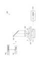
図1に示すように、レーザ加工装置100は、レーザ光Lをパルス発振するレーザ光源101と、レーザ光Lの光軸(光路)の向きを90°変えるように配置されたダイクロイックミラー103と、レーザ光Lを集光するための集光用レンズ(集光光学系)105と、を備えている。また、レーザ加工装置100は、集光用レンズ105で集光されたレーザ光Lが照射される加工対象物1を支持するための支持台107と、支持台107をX、Y、Z軸方向に移動させるためのステージ111と、レーザ光Lの出力やパルス幅等を調節するためにレーザ光源101を制御するレーザ光源制御部102と、ステージ111の移動を制御するステージ制御部115と、を備えている。 As shown in FIG. 1, a
このレーザ加工装置100においては、レーザ光源101から出射されたレーザ光Lは、ダイクロイックミラー103によってその光軸の向きを90°変えられ、支持台107上に載置された加工対象物1の内部に集光用レンズ105によって集光される。これと共に、ステージ111が移動させられ、加工対象物1がレーザ光Lに対して切断予定ライン5に沿って相対移動させられる。これにより、切断予定ライン5に沿った改質領域が加工対象物1に形成されることとなる。 In this
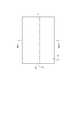
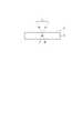
加工対象物1は、半導体材料や圧電材料等が用いられ、図2に示すように、加工対象物1には、加工対象物1を切断するための切断予定ライン5が設定されている。切断予定ライン5は、直線状に延びた仮想線である。加工対象物1の内部に改質領域を形成する場合、図3に示すように、加工対象物1の内部に集光点Pを合わせた状態で、レーザ光Lを切断予定ライン5に沿って(すなわち、図2の矢印A方向に)相対的に移動させる。これにより、図4〜図6に示すように、改質領域7が切断予定ライン5に沿って加工対象物1の内部に形成され、切断予定ライン5に沿って形成された改質領域7が切断起点領域8となる。 As the
なお、集光点Pとは、レーザ光Lが集光する箇所のことである。また、切断予定ライン5は、直線状に限らず曲線状であってもよいし、仮想線に限らず加工対象物1の表面3に実際に引かれた線であってもよい。また、改質領域7は、連続的に形成される場合もあるし、断続的に形成される場合もある。また、改質領域7は列状でも点状でもよく、要は、改質領域7は少なくとも加工対象物1の内部に形成されていればよい。また、改質領域7を起点に亀裂が形成される場合があり、亀裂及び改質領域7は、加工対象物1の外表面(表面、裏面、若しくは外周面)に露出していてもよい。 In addition, the condensing point P is a location where the laser light L is condensed. Further, the planned
ちなみに、ここでは、レーザ光Lが、加工対象物1を透過すると共に加工対象物1の内部の集光点近傍にて特に吸収され、これにより、加工対象物1に改質領域7が形成される(すなわち、内部吸収型レーザ加工)。よって、加工対象物1の表面3ではレーザ光Lが殆ど吸収されないので、加工対象物1の表面3が溶融することはない。一般的に、表面3から溶融され除去されて穴や溝等の除去部が形成される(表面吸収型レーザ加工)場合、加工領域は表面3側から徐々に裏面側に進行する。 Incidentally, here, the laser beam L passes through the
ところで、本実施形態に係るレーザ加工装置にて形成される改質領域は、密度、屈折率、機械的強度やその他の物理的特性が周囲とは異なる状態になった領域をいう。改質領域としては、例えば、溶融処理領域、クラック領域、絶縁破壊領域、屈折率変化領域等があり、これらが混在した領域もある。さらに、改質領域としては、加工対象物の材料において改質領域の密度が非改質領域の密度と比較して変化した領域や、格子欠陥が形成された領域がある(これらをまとめて高密転移領域ともいう)。 By the way, the modified region formed by the laser processing apparatus according to the present embodiment refers to a region in which density, refractive index, mechanical strength, and other physical characteristics are different from the surroundings. Examples of the modified region include a melt treatment region, a crack region, a dielectric breakdown region, a refractive index change region, and the like, and there is a region where these are mixed. Furthermore, as the modified region, there are a region where the density of the modified region in the material of the workpiece is changed compared to the density of the non-modified region, and a region where lattice defects are formed. Also known as the metastatic region).
また、溶融処理領域や屈折率変化領域、改質領域の密度が非改質領域の密度と比較して変化した領域、格子欠陥が形成された領域は、更にそれら領域の内部や改質領域と非改質領域との界面に亀裂(割れ、マイクロクラック)を内包している場合がある。内包される亀裂は改質領域の全面に渡る場合や一部分のみや複数部分に形成される場合がある。加工対象物1としては、例えばシリコン、ガラス、LiTaO3又はサファイア(Al2O3)を含む、又はこれらからなるものが挙げられる。In addition, the area where the density of the melt-processed area, the refractive index changing area, the modified area is changed compared to the density of the non-modified area, and the area where lattice defects are formed are further divided into these areas and the modified area. In some cases, cracks (cracks, microcracks) are included in the interface with the non-modified region. The included crack may be formed over the entire surface of the modified region, or may be formed in only a part or a plurality of parts. Examples of the
[第1実施形態]
次に、第1実施形態に係るレーザ加工装置について説明する。[First Embodiment]
Next, the laser processing apparatus according to the first embodiment will be described.
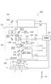
図7は、本発明の第1実施形態に係るレーザ加工装置を示す概略構成図である。図7に示すように、レーザ加工装置200は、ステージ111上の加工対象物1の内部に集光点Pを合わせてレーザ光Lを照射することにより、加工対象物1の切断予定ライン5に沿って、切断の起点となる改質領域7を形成する。このレーザ加工装置200は、レーザ光源202、反射型空間光変調器203、4f光学系241及び集光光学系204を筐体231内に備えている。 FIG. 7 is a schematic configuration diagram showing the laser processing apparatus according to the first embodiment of the present invention. As shown in FIG. 7, the
レーザ光源202は、レーザ光Lを出射するものであり、例えばファイバレーザが用いられている。ここでのレーザ光源202は、水平方向(X方向)にレーザ光を出射するように(いわゆる、横置きの状態で)筐体231の天板236にねじ等で固定されている。 The
反射型空間光変調器203は、レーザ光源202から出射されたレーザ光Lを変調するものであり、例えば反射型液晶(LCOS:Liquid Crystal on Silicon)の空間光変調器(SLM:Spatial Light Modulator)が用いられている。この反射型空間光変調器203は、水平方向に入射するレーザ光Lを、水平方向に対し斜め上方に反射しつつ、加工対象物1の内部に集光されるレーザ光L(つまり、集光位置でのレーザ光L)の収差が所定収差以下となるように変調する。換言すると、水平方向に入射するレーザ光Lを水平方向に対し上方に傾斜する方向に向けて反射すると共に、加工対象物1の内部においてレーザ光Lの波面が所定波面となるように変調する。 The reflective spatial
ここでの「所定収差以下」とは、例えば、集光位置で発生するレーザ光Lの収差を、空間光変調器203を利用せずに集光する場合と比較して小さくすることを意味している。理想的には、レーザ光Lの集光位置で発生するレーザ光Lの収差が略ゼロとなるものを意味している。 Here, “below the predetermined aberration” means, for example, that the aberration of the laser light L generated at the condensing position is reduced as compared with the case of condensing without using the spatial
図8は、図7のレーザ加工装置の反射型空間光変調器の分解斜視図である。図8に示すように、反射型空間光変調器203は、シリコン基板213と、シリコン基板213上に設けられた金属電極層214と、金属電極層214上に設けられたミラー層215と、ミラー層215上に設けられた液晶層216と、液晶層216上に設けられた透明電極層217と、透明電極層217上に設けられたガラス板218と、を備えている。 FIG. 8 is an exploded perspective view of the reflective spatial light modulator of the laser processing apparatus of FIG. As shown in FIG. 8, the reflective spatial
金属電極層214及び透明電極層217は、マトリックス状に配置された複数の電極部214a,217aを有しており、金属電極層214の各電極部214aと透明電極層217の各電極部217aとは、反射型空間光変調器203の積層方向において互いに対向している。 The
この反射型空間光変調器203では、レーザ光Lは、外部からガラス板218及び透明電極層217を順次透過して液晶層216に入射し、ミラー層215によって反射されて、液晶層216から透明電極層217及びガラス板218を順次透過して外部に出射される。このとき、互いに対向する1対の電極部214a,217a毎に電圧が印加され、その電圧に応じて、液晶層216において互いに対向する1対の電極部214a,217aに挟まれた部分の屈折率が変化している。これにより、レーザ光Lを構成する複数の光線のそれぞれにおいて、各光線の進行方向と直交する所定方向の成分の位相にずれが生じ、レーザ光Lが整形(位相変調)されることになる。 In the reflective spatial
図7に戻り、4f光学系241は、反射型空間光変調器203によって変調されたレーザ光Lの波面形状を調整するものである。この4f光学系241は、第1レンズ241a及び第2レンズ241bを有している。 Returning to FIG. 7, the 4f
レンズ241a,241bにあっては、反射型空間光変調器203と第1レンズ241aとの距離が第1レンズ241aの焦点距離f1となり、集光光学系204とレンズ241bとの距離がレンズ241bの焦点距離f2となり、第1レンズ241aと第2レンズ241bとの距離がf1+f2となり、且つ第1レンズ241aと第2レンズ241bとが両側テレセントリック光学系となるように、反射型空間光変調器203と集光光学系204との間に配置されている。 In the
この4f光学系241では、反射型空間光変調器203で位相変調され、所定ビーム径且つ集光されるレーザ光Lの収差が所定収差以下となる波面のレーザ光Lを集光光学系204で集光させることができる。焦点距離f1と焦点距離f2の比は、n:1(nは実数)であり、集光光学系204に入射するレーザ光Lのビーム径,波面は、反射型空間光変調器203で反射されるビーム径及び波面のそれぞれ1/n倍,n倍になる。また、4f光学系241では、反射型空間光変調器203で変調(補正)されたレーザ光Lが空間伝播によって波面形状が変化し収差が増大するのを抑制することができる。ここでの4f光学系241においては、集光光学系204に入射するレーザ光Lが平行光となるようにレーザ光Lが調整される。 In this 4f
集光光学系204は、4f光学系241によって変調されたレーザ光Lを加工対象物1の内部に集光するものである。この集光光学系204は、複数のレンズを含んで構成されており、圧電素子等を含んで構成された駆動ユニット232を介して筐体231の底板233に設置されている。 The condensing
なお、筐体231の外形は、その歪が低減されるような単純形状とされており、ここでは、略直方体形状を呈している。また、筐体231において両側板234、底板233、天板236及び背板(背面側の壁板)の肉厚は厚く形成されていると共に、この肉厚に比べ、筐体231において天板236よりも上部の上蓋235及び前板(前面側の壁板)の肉厚は薄く形成されている。 Note that the outer shape of the
また、レーザ加工装置200は、表面観察ユニット211及びAF(AutoFocus)ユニット(集光点位置制御手段)212を筐体231内に備えている。表面観察ユニット211は、加工対象物1の表面3を観察するためのものである。この表面観察ユニット211は、可視光VL1を出射する観察用光源211aと、加工対象物1の表面3で反射された可視光VL1の反射光VL2を受光して検出する検出器211bと、レーザ光Lを透過し且つ可視光VL1及び反射光VL2を反射するダイクロイックミラー210と、を少なくとも有している。ダイクロイックミラー210は、レーザ光Lの光路において4f光学系241と集光光学系204との間に配置されると共に、可視光VL1及び反射光VL2の向きを90°変えるように配置されている。 Further, the
この表面観察ユニット211では、観察用光源211aから出射された可視光VL1は、ミラー208及びダイクロイックミラー209,210で順次反射され、集光光学系204で集光される。また、加工対象物1の表面2で反射された反射光VL2は、集光光学系204で集光されてダイクロイックミラー210で反射され、ダイクロイックミラー209を透過する。 In the
AFユニット212は、例えば加工対象物1の表面3にうねりが存在するような場合にも、表面3から所定距離の位置にレーザ光Lの集光点Pを精度良く合わせるためのものである。このAFユニット212は、具体的には、AF用レーザ光LB1を加工対象物1に出射し、加工対象物1の表面3で反射されたAF用レーザ光LB1の反射光LB2を受光し検出することで、切断予定ライン5に沿った表面3の変位データを取得する。そして、改質領域7を形成する際に、取得した変位データに基づいて駆動ユニット232を駆動させることで、加工対象物1の表面3のうねりに沿うように集光光学系204をその光軸方向に往復移動させ、集光光学系204と加工対象物1との距離を微調整する。 The
このAFユニット212は、レーザ光Lを透過し且つAF用レーザ光LB1及び反射光LB2を反射するAF用ダイクロイックミラー238を少なくとも有している。AF用ダイクロイックミラー238は、レーザ光Lの光路において4f光学系241と集光光学系204との間においてダイクロイックミラー210の下流側に配置されると共に、AF用レーザ光LB1及び反射光LB2の向きを90°変えるように配置されている。このAF用ダイクロイックミラー238は、レーザ光Lの光路において最も下流側に配置された透過光学素子とされている。つまり、AFユニット212は、反射光LB2が他のダイクロイックミラー等の他の透過光学素子を透過しないように構成されている。 The
AF用ダイクロイックミラー238にてAF用レーザ光LB1が入射する方向及び向きは、上記のダイクロイックミラー210で可視光VL1が入射する方向及び向きと等しくなっている。つまり、ダイクロイックミラー210,218は、そのミラー面がレーザ光Lの光軸に対して同じ方向に同角度で傾斜するように設けられている。これにより、表面観察ユニット211及びAFユニット212は、筐体231内において同じ側(図示右側)に配置されることになる。 The direction and direction in which the AF laser beam LB1 is incident on the AF
また、レーザ加工装置200は、レーザ加工装置200の全体を制御するためのものとして、レーザ光源202と反射型空間光変調器203とステージ111と筐体231とAFユニット212とに接続されこれらを制御する制御部250を備えている。この制御部250は、具体的には、以下の制御を実行する。 The
すなわち、制御部250は、レーザ光源202を制御し、レーザ光源202から出射されるレーザ光Lの出力やパルス幅等を調節する。また、制御部250は、改質領域7を形成する際、レーザ光Lの集光点Pが加工対象物1の表面3から所定距離に位置し且つレーザ光Lの集光点Pが切断予定ライン5に沿って相対的に移動するように筐体231及びステージ111の少なくとも一方を制御する。 That is, the
また、制御部250は、レーザ光Lの光学特性が所定の光学特性となるように反射型空間光変調器203を制御する。例えば、改質領域7を形成する際、加工対象物1の内部に集光されるレーザ光Lの収差が所定収差以下となるように、互いに対向する1対の電極部214a,217a毎に所定電圧を印加して反射型空間光変調器203を制御する。より具体的には、制御部250は、反射型空間光変調器203に入射したレーザ光Lのビームパターン(ビーム波面)を整形(変調)させるための波面整形(収差補正)パターン情報を反射型空間光変調器203に入力する。そして、入力されたパターン情報に基づく信号によって一対の電極214a,217a毎に対応する液晶層216の屈折率を変化させ、反射型空間光変調器203から出射(反射)されるレーザ光Lのビームパターン(ビーム波面)を整形(変調)する。 In addition, the
なお、制御部250は、図示するように筐体231外に配置されてもよいし、筐体231内に設置されてもよい。また、制御部250では、反射型空間光変調器203に入力するパターン情報を逐次入力するようにしてもよいし、予め記憶されたパターン情報を選択して入力するようにしてもよい。 Note that the
ここで、本実施形態のレーザ加工装置は、レーザ光Lの光路において、レーザ光源202と反射型空間光変調器203との間に配置された一対の第1ミラー205a,205bと、反射型空間光変調器203と4f光学系241との間に配置された一対の第2ミラー206a,206bと、を備えている。 Here, the laser processing apparatus of this embodiment includes a pair of
第1ミラー205a,205bは、レーザ光源202で出射されたレーザ光Lを、反射型空間光変調器203に向けて反射する。これら第1ミラー205a,205bは、レーザ光Lの向きを90°変えるようにそれぞれ配置されている。具体的には、上流側の第1ミラー205aは、水平方向右側から入射するレーザ光Lを下方へと反射し、下流側の第1ミラー205bは、上方から入射するレーザ光Lを水平方向右側へと反射する。 The first mirrors 205 a and 205 b reflect the laser light L emitted from the
第2ミラー206a,206bは、反射型空間光変調器203で反射されたレーザ光Lを、4f光学系241に向けて反射する。具体的には、上流側の第2ミラー206aは、水平方向に対し斜め下方から入射するレーザ光Lを上方へと反射し、下流側の第2ミラー206bは、下方から入射するレーザ光Lを水平方向左側へと反射する。 The
また、ミラー205a,205b,206a,206bは、所定方向(ここでは、Y軸方向)に延在する軸を有しており、この軸回りに回転可能に構成されている。これにより、ミラー205a,205b,206a,206bは、その反射方向(反射角度)が調整可能に構成されている。従って、第1ミラー205a,205bにおいては、これらの反射方向が適宜調整され、反射型空間光変調器203に対して所定入射角度で確実にレーザ光Lが入射されるようレーザ光Lの位置及び入射角度が調整されている。また、第2ミラー206a,206bにおいては、これらの反射方向が適宜調整され、4f光学系241に対して所定入射角度で確実にレーザ光Lが入射されるようレーザ光Lの位置及び入射角度が調整されている。 The
なお、これらのミラー205a,205b,206a,206bでは、圧電素子等の電気的手段によって反射方向が調整されるように構成してもよいし、ねじ等の機械的手段によって反射方向が調整されるように構成してもよい。 The
また、レーザ光Lの光路において、下流側の第1ミラー205bと反射型空間光変調器203との間には、ビームエキスパンダ223が配置されている。ビームエキスパンダ223は、レーザ光Lのビーム径を拡大するためのものであり、凹レンズ213a及び平凸レンズ213bを有している。平凸レンズ213bは、レンズ213a,213b間の距離を可変とすべく、着脱可能とされると共にレーザ光Lの光路上の複数位置に設置可能とされている。よって、平凸レンズ213bを所望な位置に設置することで、レーザ光Lのビーム径を所望に拡大することができる。 Further, a
なお、ビームエキスパンダ223を通過したレーザ光Lの収差を抑制するため、凹レンズ213a及び平凸レンズ213bのそれぞれの焦点距離は、例えば以下に示すように大きく設定されている。
凹レンズ213aの焦点距離:平凸レンズ213bの焦点距離=−10:+20
=−20:+40
=−30:+60In order to suppress the aberration of the laser beam L that has passed through the
Focal length of
= -20: +40
= -30: +60
また、レーザ光Lの光路において第1ミラー205a,205b間には、アッテネータ207が配置されている。アッテネータ207は、レーザ光Lの光強度の調整を行うためのものである。このアッテネータ207は、直線偏光を得るための偏光板207aと、偏光方向を変更させるためのλ/2波長板207bと、を含んで構成されている。 Further, an
また、レーザ光Lの光路において第2ミラー206a,206b間には、偏光方向を変更させるためのλ/2波長板228が配置されている。このλ/2波長板228により、加工進行方向(切断予定ライン5に沿う方向)にレーザ光Lの偏光方向を対応させることが可能となる。 In addition, a λ / 2
以上のように構成されたレーザ加工装置100を用いて加工対象物1を切断する場合、まず、加工対象物1の裏面に、例えばエキスパンドテープを貼り付けて当該加工対象物1をステージ111上に載置する。続いて、加工対象物1の表面3からシリコンウェハ11の内部に集光点を合わせてレーザ光Lを照射して、切断予定ライン5に沿って改質領域7を加工対象物1の内部に形成する。そして、エキスパンドテープを拡張させる。これにより、改質領域7を切断の起点として、加工対象物1が切断予定ライン5に沿って精度よく切断され、複数の半導体チップが互いに離間することになる。 When cutting the
ここで、レーザ光源202から出射されたレーザ光Lにあっては、筐体231内において水平方向に進行した後、第1ミラー205aによって下方に反射され、アッテネータ207によって光強度が調整される。その後、第1ミラー205bによって水平方向に反射され、ビームエキスパンダ223によってビーム径が拡大されて反射型空間光変調器203に入射する。 Here, the laser light L emitted from the
反射型空間光変調器203に入射したレーザ光Lは、当該反射型空間光変調器203にて加工対象物1の内部に集光されるレーザ光Lの収差が所定収差以下となるように変調(補正)され、水平方向に対し斜め上方に出射される。その後、第2ミラー206aによって上方に反射された後、λ/2波長板228によって偏光方向が変更され、第2ミラー206bによって水平方向に反射されて4f光学系241に入射する。 The laser light L incident on the reflective spatial
4f光学系241に入射したレーザ光Lは、集光光学系204に入射するレーザ光Lが平行光となるように波面形状が調整される。具体的には、かかるレーザ光Lは、第1レンズ241aを透過し収束され、ミラー219によって下方へ反射される。そして、共焦点Oを経て発散すると共に、第1ミラー205b及び反射型空間光変調器203間の光路を交差した後、第2レンズ241bを透過し、平行光となるように再び収束される。 The wavefront shape of the laser light L incident on the 4f
その後、レーザ光Lは、ダイクロイックミラー210,218を順次透過して集光光学系204に入射し、ステージ111上に載置された加工対象物1の内部に集光光学系204によって集光される。 Thereafter, the laser light L sequentially passes through the
以上、本実施形態のレーザ加工装置200では、レーザ光源202と反射型空間光変調器203との間に、レーザ光Lの反射方向を可変にした第1ミラー205a,205bが配置されている。そして、これら第1ミラー205a,205bでは、そのレーザ光Lの反射方向が適宜調整され、反射型空間光変調器203に対して所定入射角度で確実にレーザ光Lが入射されるようレーザ光Lの位置及び入射角度が調整されている。従って、反射型空間光変調器203にレーザ光Lを精度よく入射させて反射型空間光変調器203を好適に機能させることができ、加工対象物1の内部に集光されるレーザ光Lの収差を抑制(低減)することが可能となる。 As described above, in the
また、本実施形態では、上述したように、レーザ光Lの集光位置で発生するレーザ光Lの収差が所定収差以下(理想的には略ゼロ)となっている。よって、集光位置でのレーザ光Lのエネルギー密度を高めることができ、切断の起点としての機能の高い(例えば、亀裂を発生させ易い)改質領域7を形成することが可能となる。すなわち、加工対象物1の内部において、小領域に選択的にレーザ光Lを集光することで周囲との温度差を大きくすることができるため、かかる小領域付近にて大きな応力を発生させることができ、よって、切断に寄与する亀裂を大きくすることが可能となる。 In the present embodiment, as described above, the aberration of the laser light L generated at the condensing position of the laser light L is equal to or less than a predetermined aberration (ideally substantially zero). Therefore, it is possible to increase the energy density of the laser light L at the condensing position, and it is possible to form the modified
また、本実施形態では、上述したように、レーザ光Lの光路において第1ミラー205bと反射型空間光変調器203との間にビームエキスパンダ223が配置されているため、ビームエキスパンダ223に対して、補正したレーザ光Lを入射させることができる。よって、レーザ光Lのビーム径を拡大するというビームエキスパンダ223の機能を充分に発揮させることが可能となる。 In the present embodiment, as described above, since the
また、本実施形態のレーザ加工装置200では、上述したように、反射型空間光変調器203と4f光学系241との間に、レーザ光Lの反射方向を可変にした第2ミラー206a,206bが配置されている。そして、これら第2ミラー206a,206bでは、そのレーザ光Lの反射方向が適宜調整され、4f光学系241に対して所定入射角度で確実にレーザ光Lが入射されるようレーザ光Lの位置及び入射角度が調整されている。従って、4f光学系241にレーザ光Lを精度よく入射させて4f光学系241を好適に機能させることができ、加工対象物1の内部に集光されるレーザ光Lの収差を抑制することが可能となる。 Further, in the
ここで、ダイクロイックミラー210,218では、特にミラー面とレーザ光Lの光軸とが垂直に交差しない場合、透過するレーザ光Lが発散又は集光していると、そのレーザ光Lに非点収差が発生する(波面が歪む)ことがある。この点、本実施形態では、上述したしたように、レーザ光Lの光路において4f光学系241と集光光学系204との間にダイクロイックミラー210,218が配置されていることから、ダイクロイックミラー210,218には4f光学系241で平行光となるよう調整されたレーザ光Lが入射される。そのため、加工対象物1の内部に集光されるレーザ光Lに非点収差が生じるのを抑制することが可能となる。 Here, in the
また、本実施形態では、上述したように、レーザ光Lの光路においてビームエキスパンダ223の上流側にアッテネータ207が配置されていることから、アッテネータ207ではレーザ光Lのビーム径が小径となる。よって、アッテネータ207における偏光板207a及びλ/2波長板207b等の光学素子を小型化することが可能となる。 In the present embodiment, as described above, since the
また、本実施形態では、上述したように、レーザ光源202が横置きの状態で筐体231に設置されているため、レーザ光源202を容易に載せ替えることができる。 In the present embodiment, as described above, since the
また、本実施形態では、上述したように、AF用レーザ光LB1及び反射光LB2がダイクロイックミラー等の他の透過光学素子を透過しないようにAFユニット212が構成されている。よって、AFユニット212では、反射光LB2を精度よく検出することができ、集光光学系204と加工対象物1との距離を高い精度で微調整することが可能となる。 In the present embodiment, as described above, the
ところで、第2ミラー206a,206bによって4f光学系241にレーザ光Lを精度よく入射させるという上記効果を発揮するためには、第1レンズ241aを第2ミラー206bの下流側に配置することが要される。この点、本実施形態では、反射型空間光変調器203が水平方向に対し斜め上方にレーザ光Lを反射するため、第1レンズ241aと反射型空間光変調器203との距離を焦点距離f1にしつつ、第1レンズ241aを第2ミラー206bの下流側に配置することが容易となる。 By the way, in order to exert the above-described effect that the laser light L is accurately incident on the 4f
なお、本実施形態では、レーザ光Lの光路がX−Z平面上(一平面上)にあり、Y方向(紙面垂直方向)に進行しないため、ミラー205a,205b,206a,206bを容易に調整することができる。つまり、例えばミラー205a,205b,206a,206bにおける反射方向の調整に際しては、Y軸回り回転方向のみを調整すればよいことになる。 In the present embodiment, the optical path of the laser light L is on the XZ plane (on one plane) and does not travel in the Y direction (perpendicular to the paper surface), so that the
また、本実施形態では、反射型空間光変調器203、表面観察ユニット211及びAFユニット212が、筐体231内において水平方向の一方側(図示右側)に設置されている。よって、これらに接続される配線をコンパクトにまとめることが可能となる。さらに、この場合、筐体231内において水平方向の他方側(図示左側)にスペースSを形成できるため、例えば、加工対象物1の内部を観察するための内部光源をこのスペースSに取り付けることも可能となる。 In the present embodiment, the reflective spatial
なお、位相変調を行うために制御部250から反射型空間光変調器203に入力されるパターン情報によって、加工対象物1に集光するレーザ光Lの入射角(以下、「NA」という)が変化することがある。この変化量は小さいものの、精密な改質領域7を形成する場合には問題となる場合がある。例えば、所定NAに比べてNAが小さくなると、切断の起点としての機能の高い改質領域7を形成することが困難となるおそれがある。よって、本実施形態では、良好な改質領域7が形成されるための所定範囲内にNAが維持されるように、制御部250にてレーザ光Lの位相変調を制御している。 The incident angle (hereinafter referred to as “NA”) of the laser beam L focused on the
また、NAが所定範囲内に維持されていても、位相変調によりNAが変化すると加工位置(集光点位置)が変化するおそれがある。従って、本実施形態では、制御部250による制御によって、加工対象物1の内部に集光されるレーザ光Lの収差を補正すると共に、所定の加工位置を維持するように集光光学系204と加工対象物1との距離を調整している。 Even if the NA is maintained within a predetermined range, if the NA changes due to phase modulation, the processing position (condensing point position) may change. Therefore, in the present embodiment, the control by the
ちなみに、反射型空間光変調器203では、その画素構造により位相変調量が制限される場合がある。よって、本実施形態の制御部250では、収差を十分に補正するための波面を正確に再現するため、位相変調量が低減されるように位相変調量に応じて集光光学系204と加工対象物1との距離を調整している。 Incidentally, in the reflective spatial
[第2実施形態]
次に、第2実施形態に係るレーザ加工装置について説明する。図9は、本発明の第2実施形態に係るレーザ加工装置を示す概略構成図である。図9に示すように、本実施形態のレーザ加工装置300が上記第1実施形態と異なる点は、ビームエキスパンダ223(図7参照)に代えてビームホモジナイザ301を備えた点である。[Second Embodiment]
Next, a laser processing apparatus according to the second embodiment will be described. FIG. 9 is a schematic configuration diagram showing a laser processing apparatus according to the second embodiment of the present invention. As shown in FIG. 9, the
ビームホモジナイザ301は、レーザ光Lの強度分布を均一化するためのものであり、
非球面レンズ301a,301bを有している。このビームホモジナイザ301は、レーザ光Lの光路において第1ミラー205bと反射型空間光変調器203との間に配置されている。The
本実施形態においても、上記効果と同様な効果、すなわち、加工対象物1の内部に集光されるレーザ光Lの収差を抑制するという効果を奏する。また、本実施形態では、ビームホモジナイザ301によってガウシアン分布を呈するレーザ光Lの強度分布を均一化することができ、改質領域7を精度よく形成することが可能となる。 Also in the present embodiment, there is an effect similar to the above effect, that is, an effect of suppressing the aberration of the laser light L condensed inside the
[第3実施形態]
次に、第3実施形態に係るレーザ加工装置について説明する。図10は、本発明の第3実施形態に係るレーザ加工装置を示す概略構成図である。図10に示すように、本実施形態のレーザ加工装置400が上記第1実施形態と異なる点は、反射型空間光変調器203(図7参照)に代えて反射型空間光変調器403を備えた点である。[Third Embodiment]
Next, a laser processing apparatus according to the third embodiment will be described. FIG. 10 is a schematic configuration diagram showing a laser processing apparatus according to the third embodiment of the present invention. As shown in FIG. 10, the
反射型空間光変調器403は、水平方向から入射するレーザ光Lを、水平方向に対し斜め下方に反射する。これにより、反射型空間光変調器203から出射されたレーザ光Lは、第2ミラー206aによって上方に反射された後、反射型空間光変調器203に入射するレーザ光Lと交差する。 The reflective spatial
また、反射型空間光変調器403は、上記反射型空間光変調器203に比べて水平方向右側の位置に配置されている。つまり、反射型空間光変調器403は、上記反射型空間光変調器203に対しレーザ光Lの入射方向奥側にずれている。これにより、第1レンズ241aと反射型空間光変調器403との距離を焦点距離f1にしつつ、第1レンズ241aを第2ミラー206bの下流側に配置することが可能となる。 Further, the reflective spatial
本実施形態においても、上記効果と同様な効果、すなわち、加工対象物1の内部に集光されるレーザ光Lの収差を抑制するという効果を奏する。 Also in the present embodiment, there is an effect similar to the above effect, that is, an effect of suppressing the aberration of the laser light L condensed inside the
また、本実施形態では、上述したように、反射型空間光変調器403がレーザ光Lを水平方向に対し斜め下方に反射し、反射型空間光変調器403に入射するレーザ光Lと反射するレーザ光Lとを交差させている。よって、反射型空間光変調器403に対するレーザ光Lの入射角(反射角)を小さくすることができ、液晶層216において隣り合う液晶画素間のクロストークを抑制することができる。なお、ここでの入射角(反射角)は、反射型空間光変調器403に垂直に入射する場合のレーザ光との間の角度を意味する。 In the present embodiment, as described above, the reflective spatial
[第4実施形態]
次に、第4実施形態に係るレーザ加工装置について説明する。図11は、本発明の第4実施形態に係るレーザ加工装置を示す概略構成図である。図11に示すように、本実施形態のレーザ加工装置500が上記第1実施形態と異なる点は、表面観察ユニット211(図7参照)に代えて表面観察ユニット511を備えた点である。[Fourth Embodiment]
Next, a laser processing apparatus according to the fourth embodiment will be described. FIG. 11 is a schematic configuration diagram showing a laser processing apparatus according to the fourth embodiment of the present invention. As shown in FIG. 11, the
表面観察ユニット511は、筐体231内において、レーザ光Lを介してAFユニット212と対称となる位置に配置されている。ここでは、筐体231内の水平方向左側に配置されている。この表面観察ユニット511は、上記表面観察ユニット211と同様に構成され、観察用光源511a、検出器511b及びダイクロイックミラー510を少なくとも有している。 The
ダイクロイックミラー510にて可視光VL1が入射する方向は、上記AF用ダイクロイックミラー238にてAF用レーザ光LB1が入射する方向と等しくなっている。一方、ダイクロイックミラー510にて可視光VL1が入射する向きは、上記AF用ダイクロイックミラー238にてAF用レーザ光LB1が入射する向きと反対となっている。つまり、ダイクロイックミラー510,218は、そのミラー面がレーザ光Lの光軸に対し互いに異なる方向に同角度で傾斜するように設けられている。 The direction in which the visible light VL1 is incident on the
本実施形態においても、上記効果と同様な効果、すなわち、加工対象物1の内部に集光されるレーザ光Lの収差を抑制するという効果を奏する。 Also in the present embodiment, there is an effect similar to the above effect, that is, an effect of suppressing the aberration of the laser light L condensed inside the
ところで、例えばレーザ加工装置500の製造時において、4f光学系241のレンズ241a,241b位置を調整する際には、通常、加工対象物1からのレーザ光Lの反射光を検出して行われる。このとき、前述したように、レーザ光Lの光路に対しミラー面を斜めにして配置されたダイクロイックミラーを4f光学系241と集光光学系204との間に有していると、このダイクロイックミラーを透過するレーザ光Lが発散又は集光する場合には、レーザ光L及び反射光の波面が歪んでしまう(非点収差が生じる)。そのため、反射光を精度よく検出できず、レンズ241a,241bを正確な位置に配置することが困難となる。 By the way, for example, when manufacturing the
これに対し、本実施形態では、レーザ光Lの光路における4f光学系241と集光光学系204との間に、レーザ光Lの光軸に対しミラー面が互いに異なる方向に傾斜するダイクロイックミラー510,218が設けられている。よって、ダイクロイックミラー510によるレーザ光Lの波面歪みと、AF用ダイクロイックミラー238によるレーザ光Lの波面歪みとが、互いに打ち消し合うように作用されることとなる。すなわち、ダイクロイックミラー510,218を透過するレーザ光Lが発散又は集光する場合においても、反射光の波面歪みを低減でき、4f光学系241を精度よく調整することが可能となる。 In contrast, in the present embodiment, the
[第5実施形態]
次に、第5実施形態に係るレーザ加工装置について説明する。図12は、本発明の第5実施形態に係るレーザ加工装置を示す概略構成図である。図12に示すように、本実施形態のレーザ加工装置600が上記第1実施形態と異なる点は、補正板601をさらに備えた点である。[Fifth Embodiment]
Next, a laser processing apparatus according to the fifth embodiment will be described. FIG. 12 is a schematic configuration diagram showing a laser processing apparatus according to the fifth embodiment of the present invention. As shown in FIG. 12, the
補正板601は、集光光学系204によって集光されるレーザ光Lの波面歪みを低減させるものであり、レーザ光Lの光路においてダイクロイックミラー210,218間に配置されている。 The
本実施形態においても、上記効果と同様な効果、すなわち、加工対象物1の内部に集光されるレーザ光Lの収差を抑制するという効果を奏する。また、本実施形態では、集光光学系204で集光されるレーザ光Lの波面歪みが補正板601によって低減されるため、前述した理由から、4f光学系241の調整の際にレーザ光Lの反射光における波面歪みを低減でき、4f光学系241を精度よく調整することが可能となる。 Also in the present embodiment, there is an effect similar to the above effect, that is, an effect of suppressing the aberration of the laser light L condensed inside the
[第6実施形態]
次に、第6実施形態に係るレーザ加工装置について説明する。図13は、本発明の第6実施形態に係るレーザ加工装置を示す概略構成図である。図13に示すように、本実施形態のレーザ加工装置700が上記第1実施形態と異なる点は、反射型空間光変調器203及びダイクロイックミラー210(図7参照)に代えて、反射型空間光変調器703及びダイクロイックミラー710を備えた点である。[Sixth Embodiment]
Next, a laser processing apparatus according to the sixth embodiment will be described. FIG. 13 is a schematic configuration diagram showing a laser processing apparatus according to the sixth embodiment of the present invention. As shown in FIG. 13, the
反射型空間光変調器703は、加工対象物1の内部に集光されるレーザ光Lにおいて、収差が所定収差以下となり且つ非点収差が所定非点収差以下となるように、レーザ光Lを変調(補正)する。ダイクロイックミラー710は、レーザ光Lの光路においてミラー219と第2レンズ241bとの間に配置されている。 The reflective spatial
本実施形態においても、上記効果と同様な効果、すなわち、加工対象物1の内部に集光されるレーザ光Lの収差を抑制するという効果を奏する。さらに、第2レンズ241bと集光用光学系204の集光レンズとの間の距離を短くすることができ、レーザ光Lの光路長全体を短くしてレーザ加工装置700を小型化することが可能となる。 Also in the present embodiment, there is an effect similar to the above effect, that is, an effect of suppressing the aberration of the laser light L condensed inside the
また、本実施形態では、ダイクロイックミラー710が第2レンズ241bの上流側に配置されていることから、ダイクロイックミラー710に発散光のレーザ光Lが入射されてレーザ光Lに非点収差が生じるが、本実施形態では、反射型空間光変調器703によって、この非点収差も所定非点収差以下となるように補正されて変調されるため、加工対象物1の内部に集光されるレーザ光Lに非点収差が生じるのを抑制することが可能となる。 In the present embodiment, since the
以上、本発明の好適な実施形態について説明したが、本発明は上記実施形態に限定されるものではない。例えば、上記実施形態では、表面観察ユニット211(511)及びAFユニット212を備え、4f光学系241と集光光学系204との間にダイクロイックミラー210(510,710),218が配置されているが、AFユニット212のみを備え、4f光学系241と集光光学系204との間にAF用ダイクロイックミラー238のみが配置されていてもよい。 The preferred embodiment of the present invention has been described above, but the present invention is not limited to the above embodiment. For example, in the above-described embodiment, the surface observation unit 211 (511) and the
また、上記実施形態は、一対の第1ミラー205a,205bと、一対の第2ミラー206a,206bを備えているが、第1及び第2ミラーを、それぞれ少なくとも2つ以上備えていればよい。また、上記実施形態では、ミラー205a,205b,206a,206bが軸回りに回転可能に構成されているが、これに限定されるものではなく、反射方向(反射角度)が調整可能に構成されていればよい。 Moreover, although the said embodiment is equipped with a pair of 1st mirrors 205a and 205b and a pair of
また、改質領域7を形成する際におけるレーザ光入射面は、加工対象物1の表面3に限定されず、加工対象物1の裏面であってもよい。また、切断予定ライン5に沿って複数列の改質領域7を形成しても勿論よい。 Further, the laser light incident surface in forming the modified
なお、本発明では、レーザ光が反射型空間光変調器から集光光学系に伝播したときの波面形状の変化を計測等によって求め、その波面形状の変化を考慮した波面整形(収差整形)パターン情報を反射型空間光変調器に入力することが一層好ましい。 In the present invention, the wavefront shape change (aberration shaping) pattern in consideration of the change in the wavefront shape is obtained by measuring the wavefront shape when the laser light propagates from the reflective spatial light modulator to the condensing optical system. More preferably, information is input to the reflective spatial light modulator.
1…加工対象物、7…改質領域、100,200,300,400,500,600,700…レーザ加工装置、101,202…レーザ光源、105…集光用レンズ(集光光学系)、203,403,703…反射型空間光変調器、204…集光光学系、205a,205b…第1ミラー、206a,206b…第2ミラー、210,238,510,710…ダイクロイックミラー、212…AFユニット(集光点位置制御手段)、223…ビームエキスパンダ、241…4f光学系(調整光学系)、301…ビームホモジナイザ、L…レーザ光、P…集光点。
DESCRIPTION OF
Claims (8)
Translated fromJapanese前記レーザ光を出射するレーザ光源と、
前記レーザ光源で出射された前記レーザ光を変調する反射型空間光変調器と、を備え、
前記レーザ光の光路において前記レーザ光源と前記反射型空間光変調器との間には、前記レーザ光を反射する少なくとも2つの第1ミラーが配置されており、
前記第1ミラーは、前記レーザ光の反射方向を調整可能に構成されていることを特徴とするレーザ加工装置。A laser processing apparatus that forms a modified region in the processing object by irradiating a laser beam with a condensing point inside the processing object,
A laser light source for emitting the laser light;
A reflective spatial light modulator that modulates the laser light emitted by the laser light source,
At least two first mirrors that reflect the laser light are disposed between the laser light source and the reflective spatial light modulator in the optical path of the laser light,
The laser processing apparatus, wherein the first mirror is configured to be capable of adjusting a reflection direction of the laser light.
前記レーザ光を出射するレーザ光源と、
前記レーザ光源で出射された前記レーザ光を変調する反射型空間光変調器と、
前記反射型空間光変調器で変調された前記レーザ光の波面形状を調整する調整光学系と、を備え、
前記レーザ光の光路において前記反射型空間光変調器と前記調整光学系との間には、前記レーザ光を反射する少なくとも2つの第2ミラーが配置されており、
前記第2ミラーは、前記レーザ光の反射方向を調整可能に構成されていることを特徴とするレーザ加工装置。A laser processing apparatus that forms a modified region in the processing object by irradiating a laser beam with a condensing point inside the processing object,
A laser light source for emitting the laser light;
A reflective spatial light modulator that modulates the laser light emitted by the laser light source;
An adjustment optical system that adjusts the wavefront shape of the laser light modulated by the reflective spatial light modulator, and
At least two second mirrors that reflect the laser beam are disposed between the reflective spatial light modulator and the adjustment optical system in the optical path of the laser beam,
The laser processing apparatus, wherein the second mirror is configured to be capable of adjusting a reflection direction of the laser light.
前記レーザ光を出射するレーザ光源と、
前記レーザ光源で出射された前記レーザ光を変調する反射型空間光変調器と、
前記反射型空間光変調器で変調された前記レーザ光の波面形状を調整する調整光学系と、
前記調整光学系で調整された前記レーザ光を前記加工対象物の内部に集光する集光光学系と、を備え、
前記レーザ光の光路において前記調整光学系と前記集光光学系との間には、前記レーザ光を透過するダイクロイックミラーが配置されていることを特徴とするレーザ加工装置。A laser processing apparatus that forms a modified region in the processing object by irradiating a laser beam with a condensing point inside the processing object,
A laser light source for emitting the laser light;
A reflective spatial light modulator that modulates the laser light emitted by the laser light source;
An adjusting optical system for adjusting the wavefront shape of the laser light modulated by the reflective spatial light modulator;
A condensing optical system that condenses the laser light adjusted by the adjusting optical system inside the workpiece, and
A laser processing apparatus, wherein a dichroic mirror that transmits the laser light is disposed between the adjustment optical system and the condensing optical system in an optical path of the laser light.
前記ダイクロイックミラーは、前記レーザ光を透過すると共に、前記測定用レーザ光及び前記測定用レーザ光の前記反射光を反射することを特徴とする請求項3記載のレーザ加工装置。A condensing point that irradiates the processing laser beam onto the object to be processed and receives the reflected light of the measuring laser beam on the object to be processed to align the condensing point with a predetermined position of the processing object. Further comprising position control means,
The laser processing apparatus according to claim 3, wherein the dichroic mirror transmits the laser beam and reflects the measurement laser beam and the reflected light of the measurement laser beam.
前記レーザ光を出射するレーザ光源と、
前記レーザ光源で出射された前記レーザ光を変調する反射型空間光変調器と、
前記反射型空間光変調器で変調された前記レーザ光の波面形状を調整する調整光学系と、
前記調整光学系で調整された前記レーザ光を前記加工対象物の内部に集光する集光光学系と、
測定用レーザ光を前記加工対象物に照射し、前記測定用レーザ光の前記加工対象物での反射光を受光することで、前記加工対象物の所定位置に前記集光点を合わせる集光点位置制御手段と、を備え、
前記レーザ光の光路において、
前記レーザ光源と前記反射型空間光変調器との間には、前記レーザ光を反射する少なくとも2つの第1ミラーが配置され、
前記反射型空間光変調器と前記調整光学系との間には、前記レーザ光を反射する少なくとも2つの第2ミラーが配置され、
前記調整光学系と前記集光光学系との間には、前記レーザ光を透過すると共に前記測定用レーザ光及び前記測定用レーザ光の前記反射光を反射するダイクロイックミラーが配置されていることを特徴とするレーザ加工装置。A laser processing apparatus that forms a modified region in the processing object by irradiating a laser beam with a condensing point inside the processing object,
A laser light source for emitting the laser light;
A reflective spatial light modulator that modulates the laser light emitted by the laser light source;
An adjusting optical system for adjusting the wavefront shape of the laser light modulated by the reflective spatial light modulator;
A condensing optical system for condensing the laser light adjusted by the adjusting optical system inside the workpiece;
A condensing point that irradiates the processing laser beam onto the object to be processed and receives the reflected light of the measuring laser beam on the object to be processed to align the condensing point with a predetermined position of the processing object. A position control means,
In the optical path of the laser beam,
Between the laser light source and the reflective spatial light modulator, at least two first mirrors that reflect the laser light are disposed,
Between the reflective spatial light modulator and the adjustment optical system, at least two second mirrors that reflect the laser light are disposed,
A dichroic mirror that transmits the laser light and reflects the measurement laser light and the reflected light of the measurement laser light is disposed between the adjustment optical system and the condensing optical system. A featured laser processing apparatus.
2. A beam expander or a beam homogenizer is disposed between the mirror located on the most downstream side of the mirror in the optical path of the laser beam and the reflective spatial light modulator. The laser irradiation apparatus as described in any one of -7.
Priority Applications (6)
| Application Number | Priority Date | Filing Date | Title |
|---|---|---|---|
| JP2008305143AJP5254761B2 (en) | 2008-11-28 | 2008-11-28 | Laser processing equipment |
| CN200980147987.7ACN102227286B (en) | 2008-11-28 | 2009-11-20 | Laser processing device |
| KR1020117011292AKR101681337B1 (en) | 2008-11-28 | 2009-11-20 | Laser machining device |
| US13/131,429US9457424B2 (en) | 2008-11-28 | 2009-11-20 | Laser machining device |
| PCT/JP2009/069722WO2010061794A1 (en) | 2008-11-28 | 2009-11-20 | Laser machining device |
| TW098139922ATWI515066B (en) | 2008-11-28 | 2009-11-24 | Laser processing device |
Applications Claiming Priority (1)
| Application Number | Priority Date | Filing Date | Title |
|---|---|---|---|
| JP2008305143AJP5254761B2 (en) | 2008-11-28 | 2008-11-28 | Laser processing equipment |
Publications (2)
| Publication Number | Publication Date |
|---|---|
| JP2010125507A JP2010125507A (en) | 2010-06-10 |
| JP5254761B2true JP5254761B2 (en) | 2013-08-07 |
Family
ID=42225670
Family Applications (1)
| Application Number | Title | Priority Date | Filing Date |
|---|---|---|---|
| JP2008305143AActiveJP5254761B2 (en) | 2008-11-28 | 2008-11-28 | Laser processing equipment |
Country Status (6)
| Country | Link |
|---|---|
| US (1) | US9457424B2 (en) |
| JP (1) | JP5254761B2 (en) |
| KR (1) | KR101681337B1 (en) |
| CN (1) | CN102227286B (en) |
| TW (1) | TWI515066B (en) |
| WO (1) | WO2010061794A1 (en) |
Families Citing this family (31)
| Publication number | Priority date | Publication date | Assignee | Title |
|---|---|---|---|---|
| JP2012037572A (en) | 2010-08-03 | 2012-02-23 | Hamamatsu Photonics Kk | Optical system for shaping laser beam and controlling wave front |
| JP5480169B2 (en) | 2011-01-13 | 2014-04-23 | 浜松ホトニクス株式会社 | Laser processing method |
| CN102642083B (en)* | 2011-02-22 | 2015-01-07 | 陈鸿隆 | Laser processing mechanism |
| JP5775811B2 (en)* | 2011-12-26 | 2015-09-09 | 浜松ホトニクス株式会社 | Laser processing apparatus and laser processing method |
| GB2501117A (en)* | 2012-04-13 | 2013-10-16 | Isis Innovation | Laser focusing method and apparatus |
| KR101423497B1 (en)* | 2012-11-22 | 2014-07-29 | 한국기계연구원 | Laser processing device for wafer dicing and wafer dicing method using the same |
| KR101421091B1 (en)* | 2013-02-01 | 2014-07-21 | 한국기계연구원 | Micro-pattern processing device and method using ultra-short pulse laser |
| JP6270820B2 (en)* | 2013-03-27 | 2018-01-31 | 国立大学法人九州大学 | Laser annealing equipment |
| US9914183B2 (en)* | 2013-03-27 | 2018-03-13 | Hamamatsu Photonics K.K. | Laser machining device and laser machining method |
| JP6389638B2 (en)* | 2014-05-12 | 2018-09-12 | 株式会社ディスコ | Laser processing equipment |
| JP6258787B2 (en)* | 2014-05-29 | 2018-01-10 | 浜松ホトニクス株式会社 | Laser processing apparatus and laser processing method |
| KR102549649B1 (en)* | 2014-11-14 | 2023-06-29 | 가부시키가이샤 니콘 | Shaping device and a shaping method |
| JP2016111315A (en)* | 2014-11-27 | 2016-06-20 | 株式会社東京精密 | Laser beam machine and laser processing method |
| CN108290766B (en)* | 2015-11-25 | 2021-04-27 | 康宁股份有限公司 | Method of separating glass mesh |
| JP6925778B2 (en)* | 2016-01-28 | 2021-08-25 | 浜松ホトニクス株式会社 | Laser output device and laser processing device |
| WO2017130953A1 (en) | 2016-01-28 | 2017-08-03 | 浜松ホトニクス株式会社 | Laser machining device and laser output device |
| JP6644580B2 (en) | 2016-02-24 | 2020-02-12 | 浜松ホトニクス株式会社 | Laser beam irradiation device and laser beam irradiation method |
| GB201712639D0 (en)* | 2017-08-07 | 2017-09-20 | Univ Oxford Innovation Ltd | Method for laser machining inside materials |
| JP6959073B2 (en)* | 2017-08-30 | 2021-11-02 | 株式会社ディスコ | Laser processing equipment |
| CN108132511A (en)* | 2017-12-21 | 2018-06-08 | 暨南大学 | A kind of compound camera lens for diamond laser cutting |
| JP7088761B2 (en)* | 2018-07-05 | 2022-06-21 | 浜松ホトニクス株式会社 | Laser processing equipment |
| US11024501B2 (en) | 2018-12-29 | 2021-06-01 | Cree, Inc. | Carrier-assisted method for parting crystalline material along laser damage region |
| US10576585B1 (en) | 2018-12-29 | 2020-03-03 | Cree, Inc. | Laser-assisted method for parting crystalline material |
| US10562130B1 (en) | 2018-12-29 | 2020-02-18 | Cree, Inc. | Laser-assisted method for parting crystalline material |
| CN109750151B (en)* | 2019-02-22 | 2020-11-03 | 江苏大学 | A three-dimensional laser shock strengthening device |
| US10611052B1 (en) | 2019-05-17 | 2020-04-07 | Cree, Inc. | Silicon carbide wafers with relaxed positive bow and related methods |
| JP7303078B2 (en)* | 2019-09-11 | 2023-07-04 | 浜松ホトニクス株式会社 | LASER PROCESSING APPARATUS AND LASER PROCESSING METHOD |
| JP7386672B2 (en)* | 2019-11-15 | 2023-11-27 | 株式会社ディスコ | Laser processing equipment and phase pattern adjustment method |
| JP7368205B2 (en)* | 2019-12-04 | 2023-10-24 | 浜松ホトニクス株式会社 | laser processing equipment |
| JP7564719B2 (en)* | 2021-01-28 | 2024-10-09 | 浜松ホトニクス株式会社 | Laser processing device and laser processing method |
| JP2023061087A (en)* | 2021-10-19 | 2023-05-01 | 株式会社東京精密 | Optical system and laser processing device |
Family Cites Families (65)
| Publication number | Priority date | Publication date | Assignee | Title |
|---|---|---|---|---|
| US4546231A (en) | 1983-11-14 | 1985-10-08 | Group Ii Manufacturing Ltd. | Creation of a parting zone in a crystal structure |
| JP3285214B2 (en)* | 1991-03-22 | 2002-05-27 | 株式会社日立製作所 | Optical equipment for laser processing |
| JP3475947B2 (en)* | 1991-05-21 | 2003-12-10 | セイコーエプソン株式会社 | Optical device |
| DE69222113T2 (en)* | 1991-05-21 | 1998-02-05 | Seiko Epson Corp | OPTICAL DEVICE AND OPTICAL PROCESSING SYSTEM USING THE OPTICAL DEVICE |
| JP3285256B2 (en) | 1993-07-12 | 2002-05-27 | 三洋機工株式会社 | Automatic alignment adjustment method and apparatus for laser robot |
| KR0171947B1 (en) | 1995-12-08 | 1999-03-20 | 김주용 | Exposure method for manufacturing semiconductor device and exposure device using same |
| JP4251742B2 (en)* | 2000-01-14 | 2009-04-08 | 日立ビアメカニクス株式会社 | Laser processing equipment |
| WO2001053876A1 (en) | 2000-01-19 | 2001-07-26 | Hamamatsu Photonics K.K. | Laser machinning device |
| JP4659300B2 (en) | 2000-09-13 | 2011-03-30 | 浜松ホトニクス株式会社 | Laser processing method and semiconductor chip manufacturing method |
| JP2003071828A (en)* | 2001-09-03 | 2003-03-12 | Japan Science & Technology Corp | Laser micro cleaving apparatus and method |
| GB0121308D0 (en)* | 2001-09-03 | 2001-10-24 | Thomas Swan & Company Ltd | Optical processing |
| TWI326626B (en) | 2002-03-12 | 2010-07-01 | Hamamatsu Photonics Kk | Laser processing method |
| WO2003076119A1 (en) | 2002-03-12 | 2003-09-18 | Hamamatsu Photonics K.K. | Method of cutting processed object |
| EP2400539B1 (en) | 2002-03-12 | 2017-07-26 | Hamamatsu Photonics K.K. | Substrate dividing method |
| TWI520269B (en) | 2002-12-03 | 2016-02-01 | Hamamatsu Photonics Kk | Cutting method of semiconductor substrate |
| EP1588793B1 (en) | 2002-12-05 | 2012-03-21 | Hamamatsu Photonics K.K. | Laser processing devices |
| JP2004188422A (en) | 2002-12-06 | 2004-07-08 | Hamamatsu Photonics Kk | Device and method for machining laser beam |
| FR2852250B1 (en) | 2003-03-11 | 2009-07-24 | Jean Luc Jouvin | PROTECTIVE SHEATH FOR CANNULA, AN INJECTION KIT COMPRISING SUCH ANKLE AND NEEDLE EQUIPPED WITH SUCH ANKLE |
| DE60315515T2 (en) | 2003-03-12 | 2007-12-13 | Hamamatsu Photonics K.K., Hamamatsu | LASER PROCESSING PROCEDURES |
| CN101862907B (en) | 2003-07-18 | 2014-01-22 | 浜松光子学株式会社 | Laser beam machining method, laser beam machining apparatus, and laser machined product |
| JP4563097B2 (en) | 2003-09-10 | 2010-10-13 | 浜松ホトニクス株式会社 | Semiconductor substrate cutting method |
| JP2005086175A (en) | 2003-09-11 | 2005-03-31 | Hamamatsu Photonics Kk | Method of manufacturing semiconductor thin film, semiconductor thin film, semiconductor thin-film chip, electron tube and light detector |
| EP1705764B1 (en) | 2004-01-07 | 2012-11-14 | Hamamatsu Photonics K. K. | Semiconductor light-emitting device and its manufacturing method |
| JP4601965B2 (en) | 2004-01-09 | 2010-12-22 | 浜松ホトニクス株式会社 | Laser processing method and laser processing apparatus |
| JP4509578B2 (en) | 2004-01-09 | 2010-07-21 | 浜松ホトニクス株式会社 | Laser processing method and laser processing apparatus |
| JP4598407B2 (en) | 2004-01-09 | 2010-12-15 | 浜松ホトニクス株式会社 | Laser processing method and laser processing apparatus |
| KR101336402B1 (en) | 2004-03-30 | 2013-12-04 | 하마마츠 포토닉스 가부시키가이샤 | Laser processing method and semiconductor chip |
| EP1742253B1 (en) | 2004-03-30 | 2012-05-09 | Hamamatsu Photonics K.K. | Laser processing method |
| JP4536407B2 (en) | 2004-03-30 | 2010-09-01 | 浜松ホトニクス株式会社 | Laser processing method and object to be processed |
| TWI348408B (en) | 2004-04-28 | 2011-09-11 | Olympus Corp | Laser processing device |
| JP4686135B2 (en)* | 2004-04-28 | 2011-05-18 | オリンパス株式会社 | Laser processing equipment |
| JP4634089B2 (en) | 2004-07-30 | 2011-02-16 | 浜松ホトニクス株式会社 | Laser processing method |
| KR101109860B1 (en) | 2004-08-06 | 2012-02-21 | 하마마츠 포토닉스 가부시키가이샤 | Laser processing method, cutting method for work and semiconductor device |
| JP2006068762A (en)* | 2004-08-31 | 2006-03-16 | Univ Of Tokushima | Laser processing method and laser processing apparatus |
| JP4754801B2 (en) | 2004-10-13 | 2011-08-24 | 浜松ホトニクス株式会社 | Laser processing method |
| JP4917257B2 (en) | 2004-11-12 | 2012-04-18 | 浜松ホトニクス株式会社 | Laser processing method |
| JP4781661B2 (en) | 2004-11-12 | 2011-09-28 | 浜松ホトニクス株式会社 | Laser processing method |
| JP4198123B2 (en) | 2005-03-22 | 2008-12-17 | 浜松ホトニクス株式会社 | Laser processing method |
| JP4776994B2 (en) | 2005-07-04 | 2011-09-21 | 浜松ホトニクス株式会社 | Processing object cutting method |
| JP2007029959A (en)* | 2005-07-22 | 2007-02-08 | Olympus Corp | Laser beam machining apparatus |
| JP4749799B2 (en) | 2005-08-12 | 2011-08-17 | 浜松ホトニクス株式会社 | Laser processing method |
| JP4762653B2 (en) | 2005-09-16 | 2011-08-31 | 浜松ホトニクス株式会社 | Laser processing method and laser processing apparatus |
| JP4237745B2 (en) | 2005-11-18 | 2009-03-11 | 浜松ホトニクス株式会社 | Laser processing method |
| JP4907965B2 (en) | 2005-11-25 | 2012-04-04 | 浜松ホトニクス株式会社 | Laser processing method |
| JP4804911B2 (en) | 2005-12-22 | 2011-11-02 | 浜松ホトニクス株式会社 | Laser processing equipment |
| JP4907984B2 (en) | 2005-12-27 | 2012-04-04 | 浜松ホトニクス株式会社 | Laser processing method and semiconductor chip |
| JP2007227592A (en)* | 2006-02-23 | 2007-09-06 | Fujifilm Corp | Laser irradiation apparatus and laser annealing apparatus |
| EP1875983B1 (en) | 2006-07-03 | 2013-09-11 | Hamamatsu Photonics K.K. | Laser processing method and chip |
| JP5183892B2 (en) | 2006-07-03 | 2013-04-17 | 浜松ホトニクス株式会社 | Laser processing method |
| JP4954653B2 (en) | 2006-09-19 | 2012-06-20 | 浜松ホトニクス株式会社 | Laser processing method |
| CN101516566B (en) | 2006-09-19 | 2012-05-09 | 浜松光子学株式会社 | Laser processing method and laser processing apparatus |
| JP5101073B2 (en) | 2006-10-02 | 2012-12-19 | 浜松ホトニクス株式会社 | Laser processing equipment |
| JP5132911B2 (en) | 2006-10-03 | 2013-01-30 | 浜松ホトニクス株式会社 | Laser processing method |
| JP4964554B2 (en) | 2006-10-03 | 2012-07-04 | 浜松ホトニクス株式会社 | Laser processing method |
| WO2008041604A1 (en) | 2006-10-04 | 2008-04-10 | Hamamatsu Photonics K.K. | Laser processing method |
| JP4955425B2 (en) | 2007-03-08 | 2012-06-20 | オリンパス株式会社 | Laser processing equipment |
| JP5336054B2 (en) | 2007-07-18 | 2013-11-06 | 浜松ホトニクス株式会社 | Processing information supply system provided with processing information supply device |
| JP4402708B2 (en) | 2007-08-03 | 2010-01-20 | 浜松ホトニクス株式会社 | Laser processing method, laser processing apparatus and manufacturing method thereof |
| JP5225639B2 (en) | 2007-09-06 | 2013-07-03 | 浜松ホトニクス株式会社 | Manufacturing method of semiconductor laser device |
| JP5342772B2 (en) | 2007-10-12 | 2013-11-13 | 浜松ホトニクス株式会社 | Processing object cutting method |
| JP5449665B2 (en) | 2007-10-30 | 2014-03-19 | 浜松ホトニクス株式会社 | Laser processing method |
| JP5134928B2 (en) | 2007-11-30 | 2013-01-30 | 浜松ホトニクス株式会社 | Workpiece grinding method |
| JP5054496B2 (en) | 2007-11-30 | 2012-10-24 | 浜松ホトニクス株式会社 | Processing object cutting method |
| US20090212030A1 (en)* | 2008-02-25 | 2009-08-27 | Optisolar, Inc., A Delaware Corporation | Autofocus for Ablation Laser |
| JP5241525B2 (en) | 2009-01-09 | 2013-07-17 | 浜松ホトニクス株式会社 | Laser processing equipment |
- 2008
- 2008-11-28JPJP2008305143Apatent/JP5254761B2/enactiveActive
- 2009
- 2009-11-20CNCN200980147987.7Apatent/CN102227286B/enactiveActive
- 2009-11-20USUS13/131,429patent/US9457424B2/enactiveActive
- 2009-11-20KRKR1020117011292Apatent/KR101681337B1/enactiveActive
- 2009-11-20WOPCT/JP2009/069722patent/WO2010061794A1/enactiveApplication Filing
- 2009-11-24TWTW098139922Apatent/TWI515066B/enactive
Also Published As
| Publication number | Publication date |
|---|---|
| KR101681337B1 (en) | 2016-11-30 |
| US20110266261A1 (en) | 2011-11-03 |
| CN102227286A (en) | 2011-10-26 |
| TW201029782A (en) | 2010-08-16 |
| KR20110099091A (en) | 2011-09-06 |
| US9457424B2 (en) | 2016-10-04 |
| TWI515066B (en) | 2016-01-01 |
| WO2010061794A1 (en) | 2010-06-03 |
| CN102227286B (en) | 2016-03-16 |
| JP2010125507A (en) | 2010-06-10 |
Similar Documents
| Publication | Publication Date | Title |
|---|---|---|
| JP5254761B2 (en) | Laser processing equipment | |
| JP6353683B2 (en) | Laser processing apparatus and laser processing method | |
| JP6258787B2 (en) | Laser processing apparatus and laser processing method | |
| JP6272145B2 (en) | Laser processing apparatus and laser processing method | |
| JP5451238B2 (en) | Laser processing method | |
| US12280443B2 (en) | Laser machining device | |
| US9821408B2 (en) | Laser machining method and laser machining device | |
| JP6786374B2 (en) | Laser processing equipment and laser processing method | |
| US11484968B2 (en) | Laser light irradiation device and laser light irradiation method | |
| JP2009034723A (en) | Laser beam machining method, laser beam machining apparatus and method of manufacturing it | |
| TW201919806A (en) | Laser processing device | |
| JP2011110567A (en) | Laser beam machining method | |
| TW201819083A (en) | Laser light irradiating device | |
| WO2013039006A1 (en) | Laser machining method | |
| TW201803673A (en) | Laser processing device |
Legal Events
| Date | Code | Title | Description |
|---|---|---|---|
| A621 | Written request for application examination | Free format text:JAPANESE INTERMEDIATE CODE: A621 Effective date:20111111 | |
| TRDD | Decision of grant or rejection written | ||
| A01 | Written decision to grant a patent or to grant a registration (utility model) | Free format text:JAPANESE INTERMEDIATE CODE: A01 Effective date:20130326 | |
| A61 | First payment of annual fees (during grant procedure) | Free format text:JAPANESE INTERMEDIATE CODE: A61 Effective date:20130418 | |
| R150 | Certificate of patent or registration of utility model | Ref document number:5254761 Country of ref document:JP Free format text:JAPANESE INTERMEDIATE CODE: R150 Free format text:JAPANESE INTERMEDIATE CODE: R150 | |
| FPAY | Renewal fee payment (event date is renewal date of database) | Free format text:PAYMENT UNTIL: 20160426 Year of fee payment:3 | |
| R250 | Receipt of annual fees | Free format text:JAPANESE INTERMEDIATE CODE: R250 | |
| R250 | Receipt of annual fees | Free format text:JAPANESE INTERMEDIATE CODE: R250 |