JP5254499B2 - Optical fiber cable with engagement member - Google Patents
Optical fiber cable with engagement memberDownload PDFInfo
- Publication number
- JP5254499B2 JP5254499B2JP2012532971AJP2012532971AJP5254499B2JP 5254499 B2JP5254499 B2JP 5254499B2JP 2012532971 AJP2012532971 AJP 2012532971AJP 2012532971 AJP2012532971 AJP 2012532971AJP 5254499 B2JP5254499 B2JP 5254499B2
- Authority
- JP
- Japan
- Prior art keywords
- sheath
- optical fiber
- fiber cable
- engaging member
- slit
- Prior art date
- Legal status (The legal status is an assumption and is not a legal conclusion. Google has not performed a legal analysis and makes no representation as to the accuracy of the status listed.)
- Active
Links
- 239000013307optical fiberSubstances0.000titleclaimsdescription128
- 239000000463materialSubstances0.000claimsdescription71
- 230000002093peripheral effectEffects0.000claimsdescription13
- 230000003287optical effectEffects0.000abstractdescription35
- 230000008878couplingEffects0.000description16
- 238000010168coupling processMethods0.000description16
- 238000005859coupling reactionMethods0.000description16
- 230000000694effectsEffects0.000description5
- 238000005520cutting processMethods0.000description4
- 230000004048modificationEffects0.000description4
- 238000012986modificationMethods0.000description4
- 239000004698PolyethyleneSubstances0.000description3
- 238000004891communicationMethods0.000description3
- 238000010586diagramMethods0.000description3
- 239000000835fiberSubstances0.000description3
- 238000012545processingMethods0.000description3
- 229910000838Al alloyInorganic materials0.000description2
- 229920006231aramid fiberPolymers0.000description2
- 238000004519manufacturing processMethods0.000description2
- 230000013011matingEffects0.000description2
- 238000000034methodMethods0.000description2
- -1polyethylenePolymers0.000description2
- 229920000573polyethylenePolymers0.000description2
- 230000008569processEffects0.000description2
- 239000011347resinSubstances0.000description2
- 229920005989resinPolymers0.000description2
- 238000004904shorteningMethods0.000description2
- 238000005549size reductionMethods0.000description2
- RNFJDJUURJAICM-UHFFFAOYSA-N2,2,4,4,6,6-hexaphenoxy-1,3,5-triaza-2$l^{5},4$l^{5},6$l^{5}-triphosphacyclohexa-1,3,5-trieneChemical compoundN=1P(OC=2C=CC=CC=2)(OC=2C=CC=CC=2)=NP(OC=2C=CC=CC=2)(OC=2C=CC=CC=2)=NP=1(OC=1C=CC=CC=1)OC1=CC=CC=C1RNFJDJUURJAICM-UHFFFAOYSA-N0.000description1
- 229910001369BrassInorganic materials0.000description1
- 229910000881Cu alloyInorganic materials0.000description1
- 229910052782aluminiumInorganic materials0.000description1
- XAGFODPZIPBFFR-UHFFFAOYSA-NaluminiumChemical compound[Al]XAGFODPZIPBFFR-UHFFFAOYSA-N0.000description1
- 230000015572biosynthetic processEffects0.000description1
- 239000010951brassSubstances0.000description1
- 230000008859changeEffects0.000description1
- 238000010835comparative analysisMethods0.000description1
- 239000003063flame retardantSubstances0.000description1
- 229910052736halogenInorganic materials0.000description1
- 150000002367halogensChemical class0.000description1
- 230000006872improvementEffects0.000description1
- 229910052751metalInorganic materials0.000description1
- 239000002184metalSubstances0.000description1
- 239000007769metal materialSubstances0.000description1
- 229920000915polyvinyl chloridePolymers0.000description1
- 239000004800polyvinyl chlorideSubstances0.000description1
- 239000010935stainless steelSubstances0.000description1
- 229910001220stainless steelInorganic materials0.000description1
- 238000012360testing methodMethods0.000description1
Images


Classifications
- G—PHYSICS
- G02—OPTICS
- G02B—OPTICAL ELEMENTS, SYSTEMS OR APPARATUS
- G02B6/00—Light guides; Structural details of arrangements comprising light guides and other optical elements, e.g. couplings
- G02B6/24—Coupling light guides
- G02B6/36—Mechanical coupling means
- G02B6/38—Mechanical coupling means having fibre to fibre mating means
- G02B6/3807—Dismountable connectors, i.e. comprising plugs
- G02B6/3887—Anchoring optical cables to connector housings, e.g. strain relief features
- G02B6/3888—Protection from over-extension or over-compression
- G—PHYSICS
- G02—OPTICS
- G02B—OPTICAL ELEMENTS, SYSTEMS OR APPARATUS
- G02B6/00—Light guides; Structural details of arrangements comprising light guides and other optical elements, e.g. couplings
- G02B6/44—Mechanical structures for providing tensile strength and external protection for fibres, e.g. optical transmission cables
- G02B6/4401—Optical cables
- G02B6/4429—Means specially adapted for strengthening or protecting the cables
- G02B6/443—Protective covering
Landscapes
- Physics & Mathematics (AREA)
- General Physics & Mathematics (AREA)
- Optics & Photonics (AREA)
- Mechanical Coupling Of Light Guides (AREA)
Abstract
Description
Translated fromJapanese本発明は、係合部材付き光ファイバーケーブルに関するものであり、詳しくは、光コネクタに係合することにより光ファイバーケーブルと光コネクタとを結合するための係合部材が取り付けられた係合部材付き光ファイバーケーブルに関するものである。 The present invention relates to an optical fiber cable with an engaging member, and more specifically, an optical fiber cable with an engaging member to which an engaging member for coupling the optical fiber cable and the optical connector is attached by engaging with the optical connector. It is about.
自動車などの車両においては、搭載される電装機器の増加に伴い、車両内部での情報通信量が増加してきている。光ファイバを用いる光ファイバーケーブルは、電線に比較して、多量の情報を高速に通信することができる。そこで、車両内部での情報通信量の増加対策として、情報通信媒体を電線から光ファイバーケーブルに置き換えるという対策が採られるようになってきている。 In vehicles such as automobiles, the amount of information communication within the vehicle has increased with the increase in electrical equipment installed. An optical fiber cable using an optical fiber can communicate a large amount of information at a higher speed than an electric wire. Therefore, as a countermeasure against an increase in the amount of information communication inside the vehicle, a countermeasure has been adopted in which the information communication medium is replaced with an optical fiber cable from an electric wire.
光ファイバーケーブルどうしの接続や、光ファイバーケーブルと回路基板上に設置された光送受信モジュールなどとの接続には、光コネクタが使用されるが、自動車などの車両の内部に光ファイバーケーブルを配索する作業において、光ファイバーケーブルが引っ張られて、光ファイバーケーブルと光コネクタとの間に張力が加わることがある。このため、特に自動車などの車両用の光コネクタは、光ファイバーケーブルに強固に結合されていることが要求される。また、車両または屋内で使用される比較的短尺の光ファイバーケーブルは、中心部に光ファイバとアラミド繊維等の抗張力材を収容し、その周囲をシースで保護する構造が一般的である。光ファイバーケーブル全体としての引張強度は抗張力材にて負担するが、実際の配索作業において作業者が光ファイバーケーブルを引っ張った場合、作業者が直接的に引っ張るのはシース部である。この場合、抗張力材とシースは一体化していないことから、抗張力材の固定強度は十分であっても、シース部のみ光コネクタから抜け落ちる場合がある。従って、コネクタには抗張力材とシースの双方を固定する必要がある。Optical connectors are used to connect fiber optic cables and between fiber optic cables and optical transceiver modules installed on circuit boards, but in the work of routing fiber optic cables inside vehicles such as automobiles. When the optical fiber cable is pulled, tension may be applied between the optical fiber cable and the optical connector. For this reason, in particular, an optical connector for a vehicle such as an automobile is required to be firmly coupled to an optical fiber cable. In general, a relatively short optical fiber cable used in a vehicle or indoor has a structure in which a tensile strength material such as an optical fiber and an aramid fiber is accommodated in a central portion and the periphery thereof is protected by a sheath. The tensile strength of the entire optical fiber cable is borne by the tensile strength material, but when an operator pulls the optical fiber cable in an actual routing operation, the operator directly pulls the sheath portion. In this case, since the tensile strength material and the sheath are not integrated, only the sheath portion may fall out of the optical connector even if the strength strength of the tensile strength material is sufficient. Therefore, it is necessary to fix both the tensile strength material and the sheath to the connector.
光ファイバーケーブルと光コネクタとの結合構造としては、たとえば、特許文献1に記載されるような構成が提案され、広く実用化されている。特許文献1に記載の光コネクタにおいては、フェルールを保持するためのストッパの後部とカシメリングの大径部とにより光ファイバーケーブルの抗張力材が挟持されるとともに、カシメリングの小径部とリングとにより光ファイバーケーブルのシースの端部が挟持されることにより、光コネクタが光ファイバーケーブルから外れることを防止する。 As a coupling structure between an optical fiber cable and an optical connector, for example, a configuration as described in
しかしながら、前記特許文献1に記載の光ケーブルコネクタでは抗張力材とシース部を別部材にてかしめるため、部品点数と加工工数が大きいという問題がある。この問題に対処する提案としては、たとえば、特許文献2に記載されるような構成が提案されている、特許文献2に記載の光コネクタにおいてはコード外被(シース)を厚肉化することにより、コード外被自体をカシメ用台座(特許文献1におけるカシメリングの小径部に相当)として機能させることにより、部品点数と加工工数の削減を図っている。特許文献2の構成は光ファイバーケーブルと光コネクタとの結合部の短尺化に有利であり、さらに、前提とされるシース厚肉化は光ファイバーケーブル強度増を伴うことから、狭い空間に他のワイヤハーネスと共に高密度配線される車両用途としては好都合である。しかしながら、カシメ用台座を省略していることから、シース固定に関しては十分な強度を得られないおそれがある。 However, the optical cable connector described in
上記実情に鑑み、本発明が解決しようとする課題は、部品点数と加工工数の削減を図りつつ、光ファイバーケーブルと光コネクタとの結合強度、特にシース固定強度を高めることができる係合部材付き光ファイバーケーブルを提供すること、または、光コネクタを結合するための係合部材が取り付けられた光ファイバーケーブルであって係合部材と光ファイバーケーブルとの結合強度を高めることができる係合部材付き光ファイバーケーブルを提供することである。 In view of the above circumstances, the problem to be solved by the present invention is to reduce the number of parts and the number of processing steps, and to increase the coupling strength between the optical fiber cable and the optical connector, in particular, the sheath fixing strength. An optical fiber cable provided with an engagement member for providing a cable, or an optical fiber cable to which an engagement member for coupling an optical connector is attached, which can increase the coupling strength between the engagement member and the optical fiber cable. It is to be.
前記課題を解決するため、本発明は、長手方向の端面にスリットが形成されるシースおよび前記シースの内部に配設され端部が前記スリットを通じて前記シースの外部に引き出される抗張力材を有する光ファイバーケーブルと、前記シースの外周面のうちの前記抗張力材が前記スリットを通じて前記シースの外部に引き出される位置から前記端面側に装着される内リングと、前記シースの外周面のうちの前記抗張力材が前記スリットを通じて前記シースの外部に引き出される位置から前記内リングが装着される側とは反対側に位置する第一の部分および前記内リングの外側に重畳する第二の部分とを有する係合部材とを有し、前記係合部材の第一の部分が前記シースの外周面に食い込んで前記シースに結合するとともに、前記抗張力材の前記端部が前記内リングと前記係合部材の前記第二の部分とにより挟持されることを要旨とするものである。 In order to solve the above-described problems, the present invention provides an optical fiber cable having a sheath having a slit formed in an end face in a longitudinal direction and a tensile material disposed inside the sheath and having an end portion drawn out of the sheath through the slit. An inner ring mounted on the end surface side from a position where the tensile material of the outer peripheral surface of the sheath is pulled out of the sheath through the slit, and the tensile material of the outer peripheral surface of the sheath An engagement member having a first portion located on the opposite side of the side where the inner ring is mounted from a position drawn out of the sheath through the slit and a second portion overlapping the outside of the inner ring; A first portion of the engaging member bites into an outer peripheral surface of the sheath and is coupled to the sheath, and It is an Abstract that part is clamped between said second portion of said engaging member and the inner ring.
また、前記シースに対向する2つのスリットが形成されていてもよいし、前記シースに1つのスリットが形成されていてもよいし、前記シースに3つ以上のスリットが形成されていてもよい。 Two slits facing the sheath may be formed, one slit may be formed in the sheath, or three or more slits may be formed in the sheath.
また、前記シースに形成された前記スリットの一部にのみ前記抗張力材が通されていてもよい。 Further, the tensile strength material may be passed through only a part of the slit formed in the sheath.
本発明によれば、係合部材と光ファイバーケーブルとの結合強度、特にシース固定強度の向上を図ることができる。 According to the present invention, it is possible to improve the coupling strength between the engaging member and the optical fiber cable, particularly the sheath fixing strength.
すなわち、図11(a)に示す従来構造のように、係合部材82が光ファイバーケーブル81のシース811の端面直近に装着される構成であると、係合部材82の第一の部分821よりも先端側には、シース811が圧縮変形していない部分が存在しない(または、シース811そのものが存在しない)。このため、係合部材82とシース811とは、圧縮されたシース811の外周面との摩擦力によってのみ結合している。そうすると、シース811と係合部材82との間に摩擦力よりも大きい引っ張り力が加わると、抗張力材812とシース811は一体化していないことから、図11(b)の様にシース811が係合部材82の中を軸線方向に移動して係合部材から抜け落ちる。 That is, as in the conventional structure shown in FIG. 11A, when the
これに対して、本発明によれば、係合部材の第一の部分よりも先端側には、シースが圧縮変形していない部分が存在する。このため、シースと係合部材との間に摩擦力よりも大きい引っ張り力が加わった場合であっても、シースの圧縮変形していない部分が係合部材に引っ掛かることにより、シースの移動が防止または抑制される。すなわち、シースを軸線方向に移動させるには、係合部材の第一の部分とシースとの間の摩擦力よりも大きい力をかける必要があることに加え、先端部のシースを圧縮変形させる必要がある。このため、単に摩擦力によって結合している構成と比較すると、係合部材とシースとの結合強度が高くなる(換言すると、シースを軸線方向に移動させるために必要な力が大きくなる)。 On the other hand, according to the present invention, there is a portion where the sheath is not compressed and deformed on the tip side of the first portion of the engaging member. For this reason, even when a tensile force larger than the frictional force is applied between the sheath and the engaging member, the portion of the sheath that is not compressively deformed is caught by the engaging member, thereby preventing movement of the sheath. Or suppressed. That is, in order to move the sheath in the axial direction, it is necessary to apply a force larger than the frictional force between the first portion of the engaging member and the sheath, and it is necessary to compress and deform the sheath at the distal end portion. There is. For this reason, compared with the structure which is merely coupled by the frictional force, the coupling strength between the engaging member and the sheath is increased (in other words, the force required to move the sheath in the axial direction is increased).
さらに、抗張力材がスリットを通じてシースの外側に引き出される部分は、係合部材の第一の部分よりも先端側に位置する。この部分においては、スリットに抗張力材が挟まった状態にあるから(=スリットの内部に抗張力材が介在している状態にあるから)、スリットが円周方向に押し広げられて、シースの円周方向寸法が他の部分よりも大きくなっている。そしてその結果、この部分におけるシースの外径は、他の部分よりも大きくなる。このため、この部分は、他の部分に比較して、シースが係合部材から引き抜かれることを防止または抑制する効果が高くなる。すなわち、係合部材が先端側に移動するためには、シースのこの部分を通過する必要があるが、この部分は他の部分よりも外径が大きいから、シースを圧縮変形させるために要する力が、他の部分よりも大きくなる。したがって、係合部材とシースとの結合強度が大きくなる。 Furthermore, the portion where the tensile strength material is pulled out to the outside of the sheath through the slit is located on the distal end side with respect to the first portion of the engaging member. In this part, since the tensile strength material is sandwiched between the slits (= the tensile strength material is interposed inside the slit), the slit is pushed and expanded in the circumferential direction, and the circumference of the sheath Directional dimension is larger than other parts. As a result, the outer diameter of the sheath in this portion is larger than that in other portions. For this reason, this portion has a higher effect of preventing or suppressing the sheath from being pulled out of the engaging member as compared to other portions. That is, in order for the engaging member to move to the distal end side, it is necessary to pass through this portion of the sheath, but this portion has a larger outer diameter than the other portions, so the force required to compressively deform the sheath However, it becomes larger than other parts. Therefore, the coupling strength between the engaging member and the sheath is increased.
さらに、本発明によれば、係合部材の第一の部分の軸線方向の寸法の短尺化と、係合部材と光ファイバーケーブルとの結合強度の向上の両立を図ることができる。または、係合部材の第一の部分の軸線方向の寸法を小さくしても、係合部材と光ファイバーケーブルとの結合強度が低下することを防止もしくは抑制できる。したがって、係合部材の小型化を図ることができる。そして、係合部材の小型化を図ることにより、光コネクタ全体の小型化を図ることが可能になる。 Furthermore, according to the present invention, it is possible to achieve both shortening of the axial dimension of the first portion of the engaging member and improvement of the coupling strength between the engaging member and the optical fiber cable. Or, even if the axial dimension of the first portion of the engaging member is reduced, it is possible to prevent or suppress a decrease in the coupling strength between the engaging member and the optical fiber cable. Therefore, the size of the engaging member can be reduced. And it becomes possible to achieve size reduction of the whole optical connector by achieving size reduction of an engaging member.
以下に、本発明の実施形態について、図面を参照して詳細に説明する。以下の説明において、本発明の実施形態にかかる固定具付き光ファイバーケーブルを構成する各部材の『軸線方向』とは、本発明の実施形態にかかる固定具付き光ファイバーケーブルが完成した状態を基準として光ファイバーケーブルの長手方向をいうものとする。同様に、『先端側』とは、光ファイバーケーブルの端部(ここでは、係合部材が装着される側の端部をいう)に近い側をいうものとし、『後端側』とは、光ファイバーケーブルの端部から遠い側をいうものとする。 Embodiments of the present invention will be described below in detail with reference to the drawings. In the following description, the “axial direction” of each member constituting the optical fiber cable with a fixture according to the embodiment of the present invention refers to an optical fiber based on the completed state of the optical fiber cable with a fixture according to the embodiment of the present invention. It shall mean the longitudinal direction of the cable. Similarly, the “front end side” means a side close to the end of the optical fiber cable (here, the end on the side where the engaging member is mounted), and the “rear end” means the optical fiber. The side far from the end of the cable shall be said.
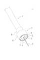
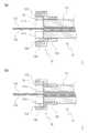
図1は、本発明の実施形態にかかる係合部材付き光ファイバーケーブル1の構成を示した分解斜視図である。図2は、本発明の実施形態にかかる係合部材付き光ファイバーケーブル1の構成を示した外観斜視図である。図3は、本発明の実施形態にかかる係合部材付き光ファイバーケーブル1の内部構造を示した断面図であり、(a)はスリットを含む面での縦断面、(b)はスリットに直交する面での縦断面である。 FIG. 1 is an exploded perspective view showing a configuration of an
図1〜図3のそれぞれに示すように、本発明の実施形態にかかる係合部材付き光ファイバーケーブル1は、光ファイバーケーブル11と、係合部材12と、内リング13とを備える。 As shown in each of FIGS. 1 to 3, the optical fiber cable with an
光ファイバーケーブル11は、従来公知の各種光ファイバーケーブルが適用できる。たとえば、次のような光ファイバーケーブル11が適用できる。光ファイバーケーブル11は、シース111と、抗張力材112と、光ファイバ113とを備える。シース111は、略チューブ状の部材であり、その内部には、軸線方向に延伸する貫通孔が形成される。シース111の断面形状は特に限定されるものではないが、ここでは、略円形である構成を例に示して説明する。そして、シース111は、外周から圧縮力が加えられると、半径方向に圧縮変形できる構成を有する。シース111は、たとえば、ポリ塩化ビニル、ポリエチレン、ノンハロゲン難燃ポリエチレンなどの各種樹脂材料により形成される。抗張力材112は、紐状の部材である。抗張力材112は、光ファイバーケーブル11に過大な張力が加わった場合に、光ファイバの破断を防止するための部材であり、たとえばアラミド繊維により形成される。光ファイバ113は、光信号を伝送する部材であり、従来公知の各種光ファイバが適用される。 Various conventionally known optical fiber cables can be applied to the
そして、光ファイバーケーブル11は、シース111に形成される貫通孔の内部に、抗張力材と光ファイバとが配設される構成を備える。また、光ファイバーケーブル11に係合部材12を組み付けるために、シース111の端部にはその端面から軸線方向に延伸するスリット1111が形成され、抗張力材112の端部がこのスリット1111を通じてシース111の外側に引き出される。 The
なお、本発明の実施形態にかかる係合部材付き光ファイバーケーブル1に適用される光ファイバーケーブル11は、シース111の内部に抗張力材112と光ファイバ113とが配設される構成のものであればよく、図1〜図3に示す構成のものに限定されるものではない。 In addition, the
係合部材12は、光コネクタ(後述)に係合することにより光ファイバーケーブル11と光コネクタとを結合するための部材であり、光ファイバーケーブル11のシース111および抗張力材112に固定される部材である。係合部材12は、第一の部分121と第二の部分122とが設けられる。第一の部分121は、光ファイバーケーブル11のシース111に固定される部分である。第二の部分122は、内リング13とともに光ファイバーケーブル11の抗張力材112を固定するための部分である。また、第二の部分122は、光コネクタに係合することにより、光ファイバーケーブル11と光コネクタとを結合する部分でもある。 The engaging
係合部材12の第一の部分121は、略環状または略筒状に形成される部分であり、軸線方向に延伸する貫通孔が形成される部分である。この貫通孔は、光ファイバーケーブル11のシース111を挿通することができる径に形成される。このため、第一の部分121に形成される貫通孔は、光ファイバーケーブル11のシース111とほぼ同じ寸法および形状に形成される構成が適用される。図1〜図3に示すように、たとえば、光ファイバーケーブル11のシース111の断面が所定の径を有する略円形であれば、係合部材12の第一の部分121の貫通孔も同じ径を有する略円形に形成される構成が適用できる。 The
係合部材12の第二の部分122も、略環状または略筒状の部分であり、軸線方向に延伸する貫通孔が形成される部分である。この貫通孔は、その内部に内リング13を挿入できる径に形成される。このため、係合部材12の第二の部分122に形成される貫通孔は、内リング13の外径よりも大きい径に形成される。 The
このように、係合部材12は、貫通孔が形成される環状または筒状の部材である。そして、貫通孔の径(=内径)が互いに異なる部分が、軸線方向に直列に設けられる。貫通孔の径が小さい部分が第一の部分121であり、貫通孔の径が大きい部分が第二の部分122である。 Thus, the engaging
内リング13は、係合部材12とともに光ファイバーケーブル11の抗張力材112を挟持して固定する部材である。内リング13は、略環状または筒状の部材であり、軸線方向に延伸する貫通孔が形成される部材である。この貫通孔は、光ファイバーケーブル11のシース材111を挿通可能な径に形成される。たとえば、シース材111の外径と略同じ径に形成される。さらに、内リング13の外周面には、光ファイバーケーブル11の抗張力材112との結合強度を向上するための凹凸が形成される。 The
係合部材12および内リング13は、たとえば、金属材料により切削加工などによって形成される構成が適用できる。なお、内リング13は、係合部材12の第二の部分122よりも変形しにくい構成を有する。たとえば、内リング13は係合部材12よりも硬い材料により形成される構成が適用される。一例として、内リング13がステンレス鋼または黄銅などの銅合金により形成され、係合部材12がアルミやアルミ合金により形成される構成が適用できる。 For example, the engaging
次に、本発明の実施形態にかかる係合部材付き光ファイバーケーブル1の製造方法について説明する。 Next, the manufacturing method of the
図4〜図7は、本発明の実施形態にかかる係合部材付き光ファイバーケーブル1を製造する際における、光ファイバーケーブル11と係合部材12と内リング13の状態を模式的に示した斜視図である。それぞれ、図4〜図6(a)は、シース111にスリット1111が形成された状態を示した斜視図、図4〜図6(b)は、シース111に形成されたスリット1111から抗張力材112が引き出された状態を示した斜視図、図4〜図6(c)は、シース111に内リング13が装着された状態を示した斜視図、図4〜図6(d)は、係合部材12の第一の部分121を内リング13の外周に重畳させた状態を示した斜視図、図7(a)は、係合部材12の第一の部分121を内リングの外周に重畳させた状態を示した断面図(=図4(d)の断面図)、図7(b)は係合部材12を圧縮変形させた状態を示した断面図である。 4-7 is the perspective view which showed typically the state of the
まず、図4〜図6(a)に示すように、光ファイバーケーブル11のシース111に、その端面から軸線方向に延伸するスリット1111が形成される。また、あらかじめ、係合部材12の貫通孔に光ファイバーケーブル11が挿通される。スリット1111の数は特に限定されるものではない。また、スリット1111は、シース111の円周方向に沿って等間隔に形成されることが好ましい。図4においては、対向する(180度間隔で)2つのスリット1111が形成される構成を示すが、図5に示すような1つのスリット1111が形成される構成や、図6に示すような3つ以上のスリット1111が形成される構成であってもよい。 First, as shown in FIGS. 4 to 6A, a
図5や図6に示した構成のように、シース111に形成されるスリット1111の数が偶数である場合、シース111にスリット1111を形成する作業が容易になる。カッターのような切断工具により、対向するスリット1111を一度に形成することができるからである。特に、2つのスリット1111が形成される構成であれば、1回の切断作業でスリット1111の形成が完了するため、工程の簡易化につながる。 When the number of
次いで、図4〜図6(b)に示すように、抗張力材112が、スリット1111を通じてシース111の外部に引き出される。複数のスリット1111が形成される構成においては、各スリット1111から引き出される抗張力材112の量が互いに等しい構成であることが好ましい。 Next, as shown in FIGS. 4 to 6B, the
ここで、図5に示す1つのスリット1111が形成される構成であれば、スリット1111に抗張力材112を通す(挟み込む)工程が簡易化できる。かかる構成は、ケーブル径が小さく、抗張力材112が少ない場合に有効である。また、図6に示す3つ以上のスリット1111が形成される構成は、ケーブル径(シース1111の径)の割に抗張力材112が多い構成のときに有利である。抗張力材112が多い場合にスリット1111が少ないと、抗張力材112が通されたスリット1111が大きく拡がってしまうおそれがあるところ、このように多くのスリット1111が形成されていれば、スリット1111の過度の拡がりが防止され、抗張力材112がスリット1111によって安定した状態で保持されるからである。 Here, if one slit 1111 shown in FIG. 5 is formed, the process of passing (stripping) the
また、図8に示すように、2つのスリット1111が形成される場合において、2つのスリット1111のうち、いずれか一方のスリット1111にのみ抗張力材112が通される構成としてもよい。つまり、ケーブル径が小さく、抗張力材112が少ない場合には、1つのスリット1111にのみ抗張力材112が通された構成とすればよいと述べたが、このような場合において、使用されないスリット1111を含めた2つのスリット1111が形成される構成としてもよい。シース111に1つのスリット1111が形成される構成とする場合、1つのスリット1111形成時に、シース111における1つのスリット1111の反対側に傷を付けてしまうおそれがあるため、1つのスリット1111のみを使用する場合であっても、使用しないスリット1111を含む2つのスリット1111が形成される構成とすれば、このようなおそれがなくなる。また、このように2つのスリット1111が形成される構成であれば、スリット1111を形成する位置を考慮しなくともよい。具体的には、1つのスリット1111のみが形成される構成であれば、1つのスリット1111の存在によりシース111の機械的強度に偏りが生じてしまい(1つのスリット1111が形成されている部分の1箇所のみが弱くなり)、ケーブルが捩れてしまうおそれのあるところ、2つのスリット1111が形成される構成であれば、このような強度の偏りによるケーブルの捩れを低減できる。 Further, as shown in FIG. 8, when two
このように、シース111に形成された複数のスリット1111のうち、一部のスリット1111にのみ抗張力材112が通され、それ以外のスリット1111は使用されない構成としてもよい。このように使用しないスリット1111が増加すると、スリット1111が形成されたシース111の先端部が拡がり、抗張力材112を挟み込む力が弱くなるということも考えられるが、本実施形態では詳細を後述する内リング13によってスリット1111が形成されたシース111の先端部が外側から押さえ込まれた状態となるから、このような問題は生じない。 In this way, the
次いで、図4〜図6(c)に示すように、内リング13が、光ファイバーケーブル11のシース111の端部の外周に装着される。内リング12がシース111の端部の外周に装着されると、シース111に形成されるスリット1111が拡がることが防止される。そして、抗張力材112は、シース111に形成されるスリット1111に挟持された状態となる。 Next, as shown in FIG. 4 to FIG. 6C, the
次いで、図4〜図6(d)と図7(a)に示すように、あらかじめ装着しておいた係合部材12を光ファイバーケーブル11の端部側に移動させ、係合部材12の第二の部分122を内リング13の外側に重畳させる。そうすると、シース111に形成されたスリット1111から引き出された抗張力材112は、係合部材112の第二の部分122の内周面と内リング13の外周面との間に位置することになる。また、係合部材12の第一の部分121は、シース111の端面から所定の距離だけ離れた箇所(=所定の距離だけ奥まった箇所)に位置する。 Next, as shown in FIG. 4 to FIG. 6D and FIG. 7A, the
次いで、図7(b)に示すように、係合部材12に外周面側から圧縮力を加え、係合部材12の半径方向の寸法が小さくなるように塑性変形させる。特に、係合部材12の第一の部分121の内径が、シース111の外径よりも小さくなるように塑性変形させる。そうすると、係合部材12の第一の部分121が、シース111に食い込んだ状態となる。また、係合部材12の第二の部分122が圧縮変形すると、シース111に形成されたスリット1111から引き出された抗張力材112が、係合部材12の第一の部分121と内リング13とに挟持される。 Next, as shown in FIG. 7B, a compressive force is applied to the engaging
このように、係合部材12の第一の部分121が光ファイバーケーブル11のシース111に食い込むことにより、係合部材12が光ファイバーケーブルのシース111に固定され、係合部材12とシース111とが一体に結合する。さらに、係合部材12と内リング13とが抗張力材を挟持することにより、係合部材12と抗張力材112とが一体に結合する。 As described above, the
本発明の実施形態にかかる係合部材付き光ファイバーケーブル1は、係合部材12の第一の部分121の先端側において、抗張力材112がスリット1111を通じてシース111の外側に引き出されている。さらに、内リング13は、係合部材12の第一の部分121および抗張力材112がスリット1111を通じてシース111の外側に引き出される位置よりも、先端側に設けられる。このため、係合部材12の第一の部分121は、シース材111端面から所定の距離だけ後端側に離れた位置に装着される。したがって、係合部材12の第一の部分121の先端側には、シース111が圧縮変形1111していない部分(換言すると、シース111の外径が、圧縮変形した後の係合部材12の第一の部分121の貫通孔の内径よりも大きい部分)が存在することになる。 In the
このような構成を有する本発明の実施形態にかかる係合部材付き光ファイバーケーブル1は、次のような作用効果を奏する。 The optical fiber cable with an
係合部材12の第一の部分121は、光ファイバーケーブル11のシース111に食い込んだ状態で装着されている。さらに、係合部材12の第一の部分121よりも先端側には、シース111が圧縮変形1111していない部分が存在する。このため、係合部材12は、シース111に、摩擦力およびシース111が圧縮変形1111していない部分とにより、シース111の外周面を移動しないように結合している。したがって、係合部材12と光ファイバーケーブル11との結合強度の向上を図ることができる。 The
すなわち、図11(a)に示す従来構造のように、係合部材82が光ファイバーケーブル81のシース811の端面直近に装着される構成であると、係合部材82の第一の部分821よりも先端側には、シース811が圧縮変形していない部分が存在しない(または、シース811そのものが存在しない)。このため、係合部材82とシース811は、圧縮されたシース811の外周面との摩擦力によってのみ結合している。そうすると、シース811と係合部材82との間に摩擦力よりも大きい引っ張り力が加わると、抗張力材812とシース811は一体化していないことから、図11(b)の様にシース811が係合部材82の中を軸線方向に移動して係合部材82から抜け落ちる。 That is, as in the conventional structure shown in FIG. 11A, when the engaging
これに対して、本発明の実施形態にかかる係合部材付き光ファイバーケーブル1においては、係合部材12の第一の部分121よりも先端側には、シース111が圧縮変形していない部分が存在する。このため、シース111と係合部材12との間に摩擦力よりも大きい引っ張り力が加わった場合であっても、シース111の圧縮変形していない部分が係合部材12に引っ掛かることにより、シース111の移動が防止または抑制される。すなわち、シース111を軸線方向に移動させるには、係合部材12の第一の部分とシース111との間の摩擦力よりも大きい力をかける必要があることに加え、先端部のシース111を圧縮変形させる必要がある。このため、単に摩擦力によって結合している構成と比較すると、係合部材12とシース111との結合強度が高くなる(換言すると、シース111を軸線方向に移動させるために必要な力が大きくなる)。 On the other hand, in the
さらに、抗張力材112がスリット1111を通じてシース111の外側に引き出される部分は、係合部材12の第一の部分121よりも先端側に位置する。この部分においては、スリット1111に抗張力材112が挟まった状態にあるから(=スリット1111の内部に抗張力材112が介在している状態にあるから)、スリット1111が円周方向に押し広げられて、シース111の円周方向寸法が他の部分よりも大きくなっている。そしてその結果、この部分におけるシース111の外径は、他の部分よりも大きくなる。このため、この部分は、他の部分に比較して、シース111が係合部材から引き抜かれることを防止または抑制する効果が高くなる。すなわち、係合部材12が先端側に移動するためには、シース111のこの部分を通過する必要があるが、この部分は他の部分よりも外径が大きいから、シース111を圧縮変形させるために要する力が、他の部分よりも大きくなる。したがって、係合部材12とシース111との結合強度が大きくなる。 Further, the portion where the
本発明の実施形態にかかる係合部材付き光ファイバーケーブル1の効果を確認するため、シース111にスリット1111の割り入れを行った場合(図3の構成)と、行わない場合(図11の構成)にてシース把持力の比較評価を行った。光ファイバーケーブルはシース外径3.0mm、内径1.5mmのPEベース樹脂のものを用い、全く同じかしめ条件にて比較を行った。係合部材12,82の材質は快削性アルミニウム合金、シース把持長5mm、かしめ後のシース111,811への食い込み量は約0.2mmである。汎用の引っ張り試験機を用い、抗張力材を引っ張ること無く、シース111,811のみを引っ張る様にして試験を行った。その結果、スリット割り入れを行わなかったものが平均15.2Nであったのに対し、スリット割り入れを行った場合、平均46.9Nと、明らかな把持力向上効果が確認出来た。 In order to confirm the effect of the
さらに、本発明の実施形態にかかる係合部材付き光ファイバーケーブル1によれば、係合部材12の第一の部分121の軸線方向の寸法の短尺化と、係合部材12と光ファイバーケーブル11との結合強度の向上の両立を図ることができる。または、係合部材12の第一の部分121の軸線方向の寸法を小さくしても、係合部材12と光ファイバーケーブル11との結合強度が低下することを防止もしくは抑制できる。したがって、係合部材12の小型化を図ることができる。そして、係合部材12の小型化を図ることにより、光コネクタ2全体の小型化を図ることが可能になる。 Furthermore, according to the
また、光ファイバーケーブル11の抗張力材112は、内リング13と係合部材12の第二の部分122とにより挟持されている。このため、抗張力材112に加わった外力(特に引っ張り力)は、光ファイバーケーブル11の抗張力材112にかかる(=抗張力材112が負担する)。したがって、係合部材12が光ファイバーケーブル11から抜けることが防止される。 The
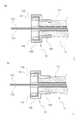
図10(a)および図10(b)は、本発明の実施形態にかかる係合部材付き光ファイバーケーブル1の変形例であり、(a)は係合部材12の第一の部分121の内面に段差を設けた例、(b)は係合部材12の第一の部分121の内面にねじを切った例である。このような構造を用いることにより、係合部材12とシース111との結合をより強固にすることが可能となる。但し、コスト的には若干不利となることから、実際の要求強度に応じた構造を適宜採用すればよい。 FIG. 10A and FIG. 10B are modifications of the
次に、本発明の実施形態にかかる係合部材付き光ファイバーケーブルに光コネクタを結合する構成について説明する。 Next, the structure which couple | bonds an optical connector with the optical fiber cable with an engaging member concerning embodiment of this invention is demonstrated.
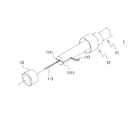
図9は、本発明の実施形態にかかる係合部材付き光ファイバーケーブル1に適用可能な(=結合可能な)光コネクタ構成を模式的に示した分解斜視(一部断面図)である。光コネクタ2は、コネクタハウジング内にフェルール(図略)や割スリーブ(図略)が収容されてなる。詳細な説明は省略するが、フェルールには、光ファイバーケーブル11の光ファイバ113の先端が固定される。割スリーブは筒状の金属製の部材であり、その後端側からフェルールの先端が挿入されている。光コネクタが図示されない相手方コネクタと嵌合すると、相手方コネクタが有するフェルールが、割スリーブの先端側から割スリーブの内側に入り込み、両フェルールの先端面同士が割スリーブ内で突き合わされる。これにより、両フェルールに固定された光ファイバが光学的に接続される。 FIG. 9 is an exploded perspective view (partially sectional view) schematically showing an optical connector configuration applicable (= connectable) to the
このような光コネクタ2のコネクタハウジングは、第一のハウジング部材21と第二のハウジング部材22と第三のハウジング部材23とを備える。そして、第一のハウジング部材21と第二のハウジング部材22とが結合して、本発明の実施形態にかかる係合部材付き光ファイバーケーブル1の係合部材12を挟持し、その先端側に第三のハウジング部材23が組み付けられる。第一のハウジング部材21と第二のハウジング部材22と第三のハウジング部材23とが結合することにより、光コネクタ2のコネクタハウジングを形成する。 Such a connector housing of the
第一のハウジング部材21と第二のハウジング部材22のそれぞれの後端側には、断面が円形に窪んだケーブル固定部211,221が形成されている。ケーブル固定部211,221は、後端側に相対的に小径の小径部2111,2211が形成され、先端側に相対的に大径(小径部より大径)の大径部2112,2212が形成される。
このような構成のケーブル固定部211,221に、光ファイバーケーブル11のシース111に固定された係合部材12が固定される。詳しくは、第一のハウジング部材21と第二のハウジング部材22が結合されることにより、係合部材12の第一の部分121がケーブル固定部211,221の小径部2111,2211に、係合部材12の第二の部分122がケーブル固定部211,221の大径部2112,2212に、挟み込まれた状態となる。相対的に大径である第一の部分121が、相対的に小径である第二の部分122よりも先端側で第一のハウジング部材と第二のハウジング部材に挟み込まれて保持されているから、光ファイバーケーブル11を引っ張っても光コネクタ2から光ファイバーケーブル11が抜けることがない。 The engaging
このように、係合部材12が光ファイバーケーブル11に固定されるとともに、係合部材12が光コネクタ2に係合する。このようにして、光ファイバーケーブル11と光コネクタ2とが結合される。 Thus, the engaging
なお、前記光コネクタ2は一例であり、適用される光コネクタの構成は限定されるものではない。 The
以上、本発明の各実施形態について詳細に説明したが、本発明は、前記各実施形態に何ら限定されるものではなく、本発明の趣旨を逸脱しない範囲において種々の改変が可能である。 As mentioned above, although each embodiment of this invention was described in detail, this invention is not limited to each said embodiment at all, and various modification | change is possible in the range which does not deviate from the meaning of this invention.
前記実施形態においては、シースが略円筒形状の光ファイバーケーブルを示したが、光ファイバーケーブルのシースの断面形状は限定されるものではない。要は、シースの内部に抗張力材と光ファイバが配設される構成を有する光ファイバーケーブルであれば、シースの断面形状に関わりなく適用できる。たとえば、断面略四角形や断面略楕円形のシースを有する光ファイバーケーブルにも適用できる。そして、このような場合には、内リングおよび係合部材の形状を、シースの断面形状に応じて設定すればよい。 In the embodiment, the optical fiber cable having a substantially cylindrical sheath is shown, but the cross-sectional shape of the sheath of the optical fiber cable is not limited. In short, any optical fiber cable having a configuration in which a tensile strength material and an optical fiber are disposed inside the sheath can be applied regardless of the cross-sectional shape of the sheath. For example, the present invention can also be applied to an optical fiber cable having a sheath having a substantially rectangular cross section or a substantially elliptical cross section. And in such a case, what is necessary is just to set the shape of an inner ring and an engaging member according to the cross-sectional shape of a sheath.
また、本発明の実施形態にかかる係合部材付き光ファイバーケーブルに適用される光ファイバーケーブルは、前記構成に限定されるものではない。シースと抗張力材を有する光ファイバーケーブルであれば適用可能である。 Moreover, the optical fiber cable applied to the optical fiber cable with the engaging member according to the embodiment of the present invention is not limited to the above configuration. Any optical fiber cable having a sheath and a tensile strength material can be applied.
Claims (5)
Translated fromJapanese前記シースの外周面のうちの前記抗張力材が前記スリットを通じて前記シースの外部に引き出される位置から前記端面側に装着される内リングと、
前記シースの外周面のうちの前記抗張力材が前記スリットを通じて前記シースの外部に引き出される位置から前記内リングが装着される側とは反対側に位置する第一の部分および前記内リングの外側に重畳する第二の部分とを有する係合部材と、
を有し、
前記係合部材の第一の部分が前記シースの外周面に食い込んで前記シースに結合するとともに、前記抗張力材の前記端部が前記内リングと前記係合部材の前記第二の部分とにより挟持されることを特徴とする係合部材付き光ファイバーケーブル。An optical fiber cable having a sheath in which a slit is formed in an end surface in a longitudinal direction and a tensile material disposed inside the sheath and having an end portion drawn out of the sheath through the slit;
An inner ring mounted on the end surface side from a position where the tensile material of the outer peripheral surface of the sheath is pulled out of the sheath through the slit;
On the outer side of the inner ring and the first portion located on the opposite side to the side on which the inner ring is mounted from the position where the tensile strength material of the outer peripheral surface of the sheath is pulled out of the sheath through the slit. An engaging member having a second portion that overlaps;
Have
The first portion of the engaging member bites into the outer peripheral surface of the sheath and is coupled to the sheath, and the end portion of the tensile strength material is sandwiched between the inner ring and the second portion of the engaging member. An optical fiber cable with an engaging member.
前記シースに形成された前記スリットの一部にのみ前記抗張力材が通されていることを特徴とする係合部材付き光ファイバーケーブル。In claim 2 or claim 4,
An optical fiber cable with an engagement member, wherein the tensile strength material is passed through only a part of the slit formed in the sheath.
Priority Applications (1)
| Application Number | Priority Date | Filing Date | Title |
|---|---|---|---|
| JP2012532971AJP5254499B2 (en) | 2010-09-06 | 2011-09-05 | Optical fiber cable with engagement member |
Applications Claiming Priority (4)
| Application Number | Priority Date | Filing Date | Title |
|---|---|---|---|
| JP2010198477 | 2010-09-06 | ||
| JP2010198477 | 2010-09-06 | ||
| PCT/JP2011/070179WO2012033057A1 (en) | 2010-09-06 | 2011-09-05 | Engagement member-equipped optical fiber cable |
| JP2012532971AJP5254499B2 (en) | 2010-09-06 | 2011-09-05 | Optical fiber cable with engagement member |
Related Child Applications (1)
| Application Number | Title | Priority Date | Filing Date |
|---|---|---|---|
| JP2013086675ADivisionJP5510583B2 (en) | 2010-09-06 | 2013-04-17 | Manufacturing method of optical fiber cable with optical connector, and optical fiber cable with optical connector |
Publications (2)
| Publication Number | Publication Date |
|---|---|
| JP5254499B2true JP5254499B2 (en) | 2013-08-07 |
| JPWO2012033057A1 JPWO2012033057A1 (en) | 2014-01-20 |
Family
ID=45810656
Family Applications (2)
| Application Number | Title | Priority Date | Filing Date |
|---|---|---|---|
| JP2012532971AActiveJP5254499B2 (en) | 2010-09-06 | 2011-09-05 | Optical fiber cable with engagement member |
| JP2013086675AActiveJP5510583B2 (en) | 2010-09-06 | 2013-04-17 | Manufacturing method of optical fiber cable with optical connector, and optical fiber cable with optical connector |
Family Applications After (1)
| Application Number | Title | Priority Date | Filing Date |
|---|---|---|---|
| JP2013086675AActiveJP5510583B2 (en) | 2010-09-06 | 2013-04-17 | Manufacturing method of optical fiber cable with optical connector, and optical fiber cable with optical connector |
Country Status (5)
| Country | Link |
|---|---|
| US (1) | US8905650B2 (en) |
| EP (1) | EP2615482B1 (en) |
| JP (2) | JP5254499B2 (en) |
| CN (1) | CN103080802B (en) |
| WO (1) | WO2012033057A1 (en) |
Cited By (1)
| Publication number | Priority date | Publication date | Assignee | Title |
|---|---|---|---|---|
| JP2013140403A (en)* | 2010-09-06 | 2013-07-18 | Auto Network Gijutsu Kenkyusho:Kk | Manufacturing method of optical fiber cable with engaging member, manufacturing method of optical fiber cable with optical connector, and optical fiber cable with optical connector |
Families Citing this family (9)
| Publication number | Priority date | Publication date | Assignee | Title |
|---|---|---|---|---|
| AU6157898A (en) | 1997-02-06 | 1998-08-26 | E. Heller & Company | Small volume (in vitro) analyte sensor |
| JP5867786B2 (en)* | 2012-03-23 | 2016-02-24 | 株式会社オートネットワーク技術研究所 | Optical fiber cable end processing structure |
| CN103969753B (en)* | 2013-01-25 | 2015-10-14 | 鸿富锦精密工业(深圳)有限公司 | The joints of optical fibre |
| JP6426145B2 (en)* | 2013-03-21 | 2018-11-21 | コーニング リサーチ アンド ディヴェロップメント コーポレイション | Optical connector for cable with sheath |
| WO2015034961A1 (en)* | 2013-09-06 | 2015-03-12 | Adc Telecommunications, Inc. | Optical fiber connector and cable assembly with dual diameter crimp sleeve |
| US9229187B2 (en)* | 2013-09-30 | 2016-01-05 | Corning Cable Systems Llc | Fan-out assemblies and fiber optic assemblies including fiber management structure for furcations |
| JP6159429B1 (en)* | 2016-01-18 | 2017-07-05 | 株式会社フジクラ | Optical connector and optical connector manufacturing method |
| USD976982S1 (en)* | 2019-05-20 | 2023-01-31 | Nico Corporation | Optic fitting set |
| JP7634314B1 (en) | 2024-08-21 | 2025-02-21 | 日東河川工業株式会社 | Repair method and device for rubber dam with deflector |
Citations (3)
| Publication number | Priority date | Publication date | Assignee | Title |
|---|---|---|---|---|
| JP2002090582A (en)* | 2000-09-14 | 2002-03-27 | Furukawa Electric Co Ltd:The | Fixing parts for optical fiber cord |
| JP2008193768A (en)* | 2007-02-01 | 2008-08-21 | Swcc Showa Cable Systems Co Ltd | Composite cable terminal, its terminal processing method, terminal fixing method, and composite cable laying method |
| JP2008191410A (en)* | 2007-02-05 | 2008-08-21 | Sumitomo Electric Ind Ltd | Optical connector |
Family Cites Families (11)
| Publication number | Priority date | Publication date | Assignee | Title |
|---|---|---|---|---|
| JPS6128163Y2 (en)* | 1980-09-22 | 1986-08-21 | ||
| JPS6388806U (en)* | 1986-11-29 | 1988-06-09 | ||
| JPH0529446Y2 (en)* | 1987-09-03 | 1993-07-28 | ||
| JPH0638481Y2 (en)* | 1987-09-21 | 1994-10-05 | 株式会社村田製作所 | Filter using composite coaxial resonator |
| JPH0497108A (en) | 1990-08-09 | 1992-03-30 | Furukawa Electric Co Ltd:The | optical connector |
| JP2000241662A (en)* | 1999-02-22 | 2000-09-08 | Seiko Instruments Inc | Optical connector and method of manufacturing optical connector |
| US7149392B2 (en)* | 2004-08-30 | 2006-12-12 | Molex Incorporated | Round multi-fiber cable assembly and a method of forming same |
| EP1932037B1 (en)* | 2005-10-05 | 2013-06-19 | Tyco Electronics Raychem BVBA | Optical fibre connection devices |
| JP4372805B2 (en)* | 2007-05-10 | 2009-11-25 | シャープ株式会社 | Photoelectric signal transmission device, photoelectric signal transmission system, and electronic apparatus using photoelectric signal transmission system |
| WO2010004772A1 (en)* | 2008-07-10 | 2010-01-14 | 株式会社フジクラ | Optical connector and method for assembling optical connector |
| JP5254499B2 (en) | 2010-09-06 | 2013-08-07 | 株式会社オートネットワーク技術研究所 | Optical fiber cable with engagement member |
- 2011
- 2011-09-05JPJP2012532971Apatent/JP5254499B2/enactiveActive
- 2011-09-05CNCN201180042796.1Apatent/CN103080802B/enactiveActive
- 2011-09-05WOPCT/JP2011/070179patent/WO2012033057A1/enactiveApplication Filing
- 2011-09-05EPEP11823532.4Apatent/EP2615482B1/enactiveActive
- 2011-09-05USUS13/704,161patent/US8905650B2/enactiveActive
- 2013
- 2013-04-17JPJP2013086675Apatent/JP5510583B2/enactiveActive
Patent Citations (3)
| Publication number | Priority date | Publication date | Assignee | Title |
|---|---|---|---|---|
| JP2002090582A (en)* | 2000-09-14 | 2002-03-27 | Furukawa Electric Co Ltd:The | Fixing parts for optical fiber cord |
| JP2008193768A (en)* | 2007-02-01 | 2008-08-21 | Swcc Showa Cable Systems Co Ltd | Composite cable terminal, its terminal processing method, terminal fixing method, and composite cable laying method |
| JP2008191410A (en)* | 2007-02-05 | 2008-08-21 | Sumitomo Electric Ind Ltd | Optical connector |
Cited By (2)
| Publication number | Priority date | Publication date | Assignee | Title |
|---|---|---|---|---|
| JP2013140403A (en)* | 2010-09-06 | 2013-07-18 | Auto Network Gijutsu Kenkyusho:Kk | Manufacturing method of optical fiber cable with engaging member, manufacturing method of optical fiber cable with optical connector, and optical fiber cable with optical connector |
| US8905650B2 (en) | 2010-09-06 | 2014-12-09 | Autonetworks Technologies, Ltd. | Fiber-optic cable with fitting |
Also Published As
| Publication number | Publication date |
|---|---|
| EP2615482A1 (en) | 2013-07-17 |
| US20130094814A1 (en) | 2013-04-18 |
| JPWO2012033057A1 (en) | 2014-01-20 |
| EP2615482A4 (en) | 2016-03-02 |
| US8905650B2 (en) | 2014-12-09 |
| JP2013140403A (en) | 2013-07-18 |
| CN103080802A (en) | 2013-05-01 |
| CN103080802B (en) | 2016-02-24 |
| WO2012033057A1 (en) | 2012-03-15 |
| EP2615482B1 (en) | 2017-10-25 |
| JP5510583B2 (en) | 2014-06-04 |
Similar Documents
| Publication | Publication Date | Title |
|---|---|---|
| JP5254499B2 (en) | Optical fiber cable with engagement member | |
| JP4976226B2 (en) | Optical connector parts and optical connectors | |
| US20150241642A1 (en) | Optical connector | |
| JP6419138B2 (en) | Optical fiber cord with connector | |
| JP5695774B1 (en) | Method for retaining optical connector and protective tube | |
| JP5621580B2 (en) | Optical cable connector and optical cable connector and optical cable assembly method | |
| WO2012137954A1 (en) | Optical connector | |
| JP5873760B2 (en) | Optical connector | |
| JP2010182632A (en) | Fixing member for cable connector, cable connector, cable with the same, and optical cable connector | |
| CN102301265B (en) | Optical connector and method for assembling the optical connector | |
| KR101459116B1 (en) | Connector for many-sided optical fiber cable | |
| CN103154796B (en) | Sleeve for optical connector and optical connector | |
| JP5418447B2 (en) | Optical cable and optical connector assembly | |
| JP2005114770A (en) | Optical connector | |
| JP2502333B2 (en) | Optical connector | |
| JP5867786B2 (en) | Optical fiber cable end processing structure | |
| JP5276905B2 (en) | Optical fiber with connector and method of assembling optical connector | |
| JP2010072172A (en) | Optical cable connector, and coupling mass of optical fiber cable and optical cable connector | |
| JP7136981B2 (en) | Connection tool and connection method for bundled hangers | |
| JPH0894877A (en) | Optical fiber connector and its assembling method | |
| JP2010072416A (en) | Optical cable connector, and coupling mass of optical fiber cable and optical cable connector | |
| CN108513601B (en) | Bending part shape-preserving structure of Bowden cable | |
| JP3313940B2 (en) | Optical amplifier | |
| JP6285708B2 (en) | Protective tube | |
| JP2012027146A (en) | Connection mechanism for optical fiber |
Legal Events
| Date | Code | Title | Description |
|---|---|---|---|
| TRDD | Decision of grant or rejection written | ||
| A01 | Written decision to grant a patent or to grant a registration (utility model) | Free format text:JAPANESE INTERMEDIATE CODE: A01 Effective date:20130319 | |
| R150 | Certificate of patent or registration of utility model | Free format text:JAPANESE INTERMEDIATE CODE: R150 Ref document number:5254499 Country of ref document:JP Free format text:JAPANESE INTERMEDIATE CODE: R150 | |
| FPAY | Renewal fee payment (event date is renewal date of database) | Free format text:PAYMENT UNTIL: 20160426 Year of fee payment:3 | |
| R250 | Receipt of annual fees | Free format text:JAPANESE INTERMEDIATE CODE: R250 | |
| R250 | Receipt of annual fees | Free format text:JAPANESE INTERMEDIATE CODE: R250 |