JP5253156B2 - Patient monitoring system and method - Google Patents
Patient monitoring system and methodDownload PDFInfo
- Publication number
- JP5253156B2 JP5253156B2JP2008515339AJP2008515339AJP5253156B2JP 5253156 B2JP5253156 B2JP 5253156B2JP 2008515339 AJP2008515339 AJP 2008515339AJP 2008515339 AJP2008515339 AJP 2008515339AJP 5253156 B2JP5253156 B2JP 5253156B2
- Authority
- JP
- Japan
- Prior art keywords
- patient
- electrodes
- electrode
- bed
- dielectric
- Prior art date
- Legal status (The legal status is an assumption and is not a legal conclusion. Google has not performed a legal analysis and makes no representation as to the accuracy of the status listed.)
- Active
Links
- 238000012544monitoring processMethods0.000titleclaimsdescription18
- 238000000034methodMethods0.000titleclaimsdescription14
- 238000005259measurementMethods0.000claimsdescription47
- 239000011159matrix materialSubstances0.000claimsdescription12
- 238000004590computer programMethods0.000description8
- 230000008878couplingEffects0.000description6
- 238000010168coupling processMethods0.000description6
- 238000005859coupling reactionMethods0.000description6
- 230000002612cardiopulmonary effectEffects0.000description5
- 230000008859changeEffects0.000description5
- 239000004744fabricSubstances0.000description2
- 210000004072lungAnatomy0.000description2
- 239000000463materialSubstances0.000description2
- 230000003071parasitic effectEffects0.000description2
- 230000008569processEffects0.000description2
- 230000035945sensitivityEffects0.000description2
- 210000000577adipose tissueAnatomy0.000description1
- 238000013459approachMethods0.000description1
- 230000001419dependent effectEffects0.000description1
- 238000000151depositionMethods0.000description1
- 238000009795derivationMethods0.000description1
- 238000001514detection methodMethods0.000description1
- 230000000694effectsEffects0.000description1
- 230000001747exhibiting effectEffects0.000description1
- 239000011888foilSubstances0.000description1
- 230000006870functionEffects0.000description1
- 208000019622heart diseaseDiseases0.000description1
- 238000012986modificationMethods0.000description1
- 230000004048modificationEffects0.000description1
- 238000012545processingMethods0.000description1
- 230000000284resting effectEffects0.000description1
- 239000000758substrateSubstances0.000description1
- 210000004243sweatAnatomy0.000description1
- 238000010998test methodMethods0.000description1
- 238000012360testing methodMethods0.000description1
- 210000001519tissueAnatomy0.000description1
- 238000003325tomographyMethods0.000description1
- XLYOFNOQVPJJNP-UHFFFAOYSA-NwaterSubstancesOXLYOFNOQVPJJNP-UHFFFAOYSA-N0.000description1
Images


Classifications
- A—HUMAN NECESSITIES
- A61—MEDICAL OR VETERINARY SCIENCE; HYGIENE
- A61B—DIAGNOSIS; SURGERY; IDENTIFICATION
- A61B5/00—Measuring for diagnostic purposes; Identification of persons
- A61B5/68—Arrangements of detecting, measuring or recording means, e.g. sensors, in relation to patient
- A61B5/6887—Arrangements of detecting, measuring or recording means, e.g. sensors, in relation to patient mounted on external non-worn devices, e.g. non-medical devices
- A61B5/6892—Mats
- A—HUMAN NECESSITIES
- A61—MEDICAL OR VETERINARY SCIENCE; HYGIENE
- A61B—DIAGNOSIS; SURGERY; IDENTIFICATION
- A61B5/00—Measuring for diagnostic purposes; Identification of persons
- A61B5/103—Measuring devices for testing the shape, pattern, colour, size or movement of the body or parts thereof, for diagnostic purposes
- A61B5/11—Measuring movement of the entire body or parts thereof, e.g. head or hand tremor or mobility of a limb
- A61B5/113—Measuring movement of the entire body or parts thereof, e.g. head or hand tremor or mobility of a limb occurring during breathing
- A—HUMAN NECESSITIES
- A61—MEDICAL OR VETERINARY SCIENCE; HYGIENE
- A61B—DIAGNOSIS; SURGERY; IDENTIFICATION
- A61B5/00—Measuring for diagnostic purposes; Identification of persons
- A61B5/24—Detecting, measuring or recording bioelectric or biomagnetic signals of the body or parts thereof
- A61B5/25—Bioelectric electrodes therefor
- A61B5/279—Bioelectric electrodes therefor specially adapted for particular uses
- A61B5/28—Bioelectric electrodes therefor specially adapted for particular uses for electrocardiography [ECG]
- A61B5/282—Holders for multiple electrodes
- A—HUMAN NECESSITIES
- A61—MEDICAL OR VETERINARY SCIENCE; HYGIENE
- A61B—DIAGNOSIS; SURGERY; IDENTIFICATION
- A61B2562/00—Details of sensors; Constructional details of sensor housings or probes; Accessories for sensors
- A61B2562/04—Arrangements of multiple sensors of the same type
- A61B2562/046—Arrangements of multiple sensors of the same type in a matrix array
- A—HUMAN NECESSITIES
- A61—MEDICAL OR VETERINARY SCIENCE; HYGIENE
- A61B—DIAGNOSIS; SURGERY; IDENTIFICATION
- A61B2562/00—Details of sensors; Constructional details of sensor housings or probes; Accessories for sensors
- A61B2562/18—Shielding or protection of sensors from environmental influences, e.g. protection from mechanical damage
- A61B2562/182—Electrical shielding, e.g. using a Faraday cage
Landscapes
- Health & Medical Sciences (AREA)
- Life Sciences & Earth Sciences (AREA)
- Molecular Biology (AREA)
- Surgery (AREA)
- Biophysics (AREA)
- Pathology (AREA)
- Engineering & Computer Science (AREA)
- Biomedical Technology (AREA)
- Heart & Thoracic Surgery (AREA)
- Medical Informatics (AREA)
- Veterinary Medicine (AREA)
- Physics & Mathematics (AREA)
- Animal Behavior & Ethology (AREA)
- General Health & Medical Sciences (AREA)
- Public Health (AREA)
- Physiology (AREA)
- Dentistry (AREA)
- Oral & Maxillofacial Surgery (AREA)
- Cardiology (AREA)
- Measuring And Recording Apparatus For Diagnosis (AREA)
- Measuring Pulse, Heart Rate, Blood Pressure Or Blood Flow (AREA)
- Measurement And Recording Of Electrical Phenomena And Electrical Characteristics Of The Living Body (AREA)
Description
Translated fromJapanese本発明は、容量性測定によって、心肺特性等をモニタリングする患者モニタリングシステムに関する。更に、本発明は、容量性測定によって、心肺特性等をモニタリングする方法に関する。 The present invention relates to a patient monitoring system that monitors cardiopulmonary characteristics and the like by capacitive measurement. Furthermore, the present invention relates to a method for monitoring cardiopulmonary characteristics and the like by capacitive measurement.
心臓病を持つ患者のパラメータのベッドサイドモニタリングは、病院のセッティングにおいて標準的である。家庭の環境において、心臓データ又は肺データを測定する第1のアプローチもある。このような家庭内モニタリングシステムをほとんど目立たなくするため、直接的な皮膚接触に頼らないセンサが、非常に魅力的にみえる。従って、容量性のセンシング方法は、最も適していることに、このようなシステムとともに使用されるべきである。 Bedside monitoring of parameters of patients with heart disease is standard in hospital settings. There is also a first approach to measuring heart data or lung data in a home environment. Sensors that do not rely on direct skin contact appear to be very attractive in order to make such home monitoring systems almost inconspicuous. Therefore, capacitive sensing methods should be used with such systems, most suitably.
生体信号の容量性センシングは、本質的に、センシング容量に対する「体電極」の容量性結合による。この結合は、患者の動き、患者の皮膚の汗、及び、センシング電極に対する体の距離又は接触の親密さに依存して変化し得る。更に、非接触センシングは、患者の体から来ない寄生信号に対して弱い。 Capacitive sensing of biological signals is essentially by capacitive coupling of “body electrodes” to the sensing capacitance. This coupling can vary depending on the patient's movement, the patient's skin sweat, and the distance of the body to the sensing electrode or the intimacy of the contact. Furthermore, non-contact sensing is vulnerable to parasitic signals that do not come from the patient's body.
本発明の目的は、特に家庭内の使用に適した、心肺特性等をモニタリングする信頼できる技術を提供することである。 An object of the present invention is to provide a reliable technique for monitoring cardiopulmonary characteristics and the like, particularly suitable for home use.
本発明によれば、この目的は、容量性測定により、心肺特性等をモニタリングする患者モニタリングシステムにより達成され、該システムは、マトリクスの形態に構成された複数の電極であって、ベッド等に一体化され、各々が個々に選択可能である電極と、ベッド等における患者の位置に依存して複数の電極を決定する手段であって、複数の電極の容量を決定することにより、複数の電極を決定する手段と、容量性測定を実行するため、複数の前記決定された電極を選択する手段とを有する。 According to the present invention, this object is achieved by a patient monitoring system that monitors cardiopulmonary characteristics, etc. by capacitive measurement, the system comprising a plurality of electrodes configured in the form of a matrix, integrated into a bed or the like. A plurality of electrodes, each of which is individually selectable, and means for determining a plurality of electrodes depending on the position of a patient in a bed, etc. Means for determining and means for selecting a plurality of said determined electrodes to perform a capacitive measurement.
本発明の目的は、容量性測定により、心肺特性をモニタリングする方法によっても達成され、該方法は、マトリクスの形態で電極を構成するステップであって、該電極がベッド等と一体化され、各々の電極が個々に選択可能であるステップと、ベッド等における患者の位置に依存して複数の電極を決定するステップであって、複数の電極の容量を決定することにより実行されるステップと、容量性の測定を実行するために複数の前記決定された電極を選択するステップとにより実行されるステップとを有する。 The object of the present invention is also achieved by a method of monitoring cardiopulmonary properties by capacitive measurement, the method comprising the steps of configuring electrodes in the form of a matrix, wherein the electrodes are integrated with a bed or the like, A plurality of electrodes individually selectable, a step of determining a plurality of electrodes depending on a position of a patient in a bed or the like, the step executed by determining a capacity of the plurality of electrodes, Selecting a plurality of the determined electrodes to perform sex measurements.
本発明の基本的な考えは、3つ又は4つの別個の電極だけでなく、互いに隣接して構成される多くの数の電極も有する電極マトリクスを使用して、容量性センシングする概念を用いることにある。これらの電極は、ベッド等と一体化され得る態様でもたらされ、例えば布地状のベッドシーツ、又はスリーピングパッド若しくはマットレスとしてもたらされる。言い換えると、患者をある「測定位置」に正確に位置させる必要はない。その代わり患者は、自分自身を任意に位置させても良い。 The basic idea of the present invention is to use the concept of capacitive sensing using an electrode matrix that has not only three or four separate electrodes, but also a large number of electrodes configured adjacent to each other. It is in. These electrodes are provided in a manner that can be integrated with a bed or the like, for example, as a fabric bed sheet, or a sleeping pad or mattress. In other words, it is not necessary to accurately position the patient at a certain “measurement position”. Instead, the patient may arbitrarily position himself.
たいていの場合において患者は電極マトリクス内のいくつかの電極をカバーするので、この場合、複数の測定電極、すなわち最終的に容量性測定を実行することに非常に適した電極を見つけるとともに、選択することが必要である。これらの電極を選択するため、本発明は、これらの測定が開始される前に、次の測定に関して電極の適合性をテストすることを提案する。 In most cases the patient covers several electrodes in the electrode matrix, so in this case find and select multiple measuring electrodes, i.e., electrodes that are ultimately very suitable for performing capacitive measurements. It is necessary. In order to select these electrodes, the present invention proposes to test the suitability of the electrodes for the next measurement before these measurements are started.
本発明によるベッドは、休むため、又は座るため等の表面又はいかなる装置、例えば従来のベッド、病院のベッド、長いす、従来の椅子、歯科の椅子、車椅子、(操作する)テーブル等として規定される。 A bed according to the present invention is defined as a surface or any device for resting or sitting, such as a conventional bed, a hospital bed, a chaise longue, a conventional chair, a dental chair, a wheelchair, a (operating) table, etc. The
提案されたシステム及び方法は、例えばECG/心拍数信号検出、EEG,EMG、生体インピーダンス測定、例えば生体インピーダンストモグラフィ、及び類似の測定のために使用され得る。 The proposed system and method can be used for eg ECG / heart rate signal detection, EEG, EMG, bioimpedance measurements, eg bioimpedance tomography, and similar measurements.
本発明のこれら及び他の態様は、従属請求項において規定される以下の実施例に基づいて、更に明らかにされるであろう。 These and other aspects of the invention will be further elucidated on the basis of the following examples, which are defined in the dependent claims.
本発明の好ましい実施例によると、システムは、誘電体を有し、該誘電体は、弾性構造からなる。誘電体として、いかなる適切な種類の材料、例えば布地のベッドシーツ等が使用されてもよい。システムは、複数の電極対であって、各々の電極対が、患者に面する誘電体の側に位置された対向電極と、誘電体の反対側に位置されるセンシング電極とにより形成される電極対と、複数の電極対の容量を決定する手段とを更に有する。患者がベッド等の上に位置される場合において、誘電体が、患者により圧迫されるように構成される場合、患者の位置に依存する電極対の容量の変化が、決定され得る。患者が電極対の上部電極を押し下げる場合、誘電体は圧縮され、上部電極と下部電極との間の距離は減少するであろう。従って容量は、増加するであろう。容量の増加は、例えば単純なブリッジ回路により、容易に検出され得る。 According to a preferred embodiment of the present invention, the system has a dielectric, which consists of an elastic structure. Any suitable type of material may be used as the dielectric, such as a fabric bed sheet. The system comprises a plurality of electrode pairs, each electrode pair formed by a counter electrode positioned on the side of the dielectric facing the patient and a sensing electrode positioned on the opposite side of the dielectric The apparatus further includes a pair and means for determining a capacity of the plurality of electrode pairs. When the patient is positioned on a bed or the like, if the dielectric is configured to be squeezed by the patient, the change in electrode pair capacitance depending on the position of the patient can be determined. If the patient depresses the upper electrode of the electrode pair, the dielectric will be compressed and the distance between the upper and lower electrodes will decrease. The capacity will therefore increase. The increase in capacity can be easily detected, for example by a simple bridge circuit.
上述のように対向電極を使う代わりに、本発明の他の好ましい実施例において、患者の体が、「対向(counter)電極」として使用される。 Instead of using a counter electrode as described above, in another preferred embodiment of the invention, the patient's body is used as the “counter electrode”.
この実施例によると、システムは、患者がベッド等の上に位置される場合、患者に面する態様で、複数の電極に隣接して位置された誘電体を有する。患者は、誘電体を直接押し下げ、容量の増加をもたらし、該増加は、ここでも例えば単純なブリッジ回路により容易に検出され得る。 According to this embodiment, the system has a dielectric positioned adjacent to the plurality of electrodes in a manner that faces the patient when the patient is positioned on a bed or the like. The patient directly depresses the dielectric, resulting in an increase in capacitance, which again can be easily detected, for example by a simple bridge circuit.
両方の場合において、高い容量をもつ電極が、実際の測定を実行するのに非常に適しており、それゆえ(事前に)選択されるであろう。 In both cases, an electrode with a high capacity is very suitable for carrying out the actual measurement and will therefore be (pre) selected.
本発明の他の実施例において、電極は、電圧信号を複数の第1電極に対して供給するとともに、複数の第2電極において、誘導される電荷を求めることにより、能動的にプロービングされる。隣接する電極は、好ましくは、第1及び第2電極として使用される。容量は電極と患者の体との間の距離に依存するので、高い信号カップリングをもつ電極が、実際の測定を実行するのに非常に適切であり、(事前に)選択されるであろう。 In another embodiment of the invention, the electrodes are actively probed by supplying voltage signals to the plurality of first electrodes and determining the induced charge at the plurality of second electrodes. Adjacent electrodes are preferably used as the first and second electrodes. Since the capacitance depends on the distance between the electrode and the patient's body, an electrode with high signal coupling is very suitable for performing the actual measurement and will be selected (pre-) .
本発明の更なる実施例において、システムは、患者と複数の電極との間、又は、患者と誘電体との間に遮蔽部を有する。遮蔽部により、前記電極の極周辺部に属する信号のみが検出されることは保証されるであろう。 In a further embodiment of the invention, the system has a shield between the patient and the electrodes or between the patient and the dielectric. It will be ensured that only the signal belonging to the pole periphery of the electrode is detected by the shielding.
適切な電極、すなわち、高い容量及び/又は高い信号カップリングを示す電極が(事前に)選択されている場合、実際の測定、例えば心拍数信号の測定は、前記電極を用いて実施される。適切な電極を選択するプロセスは、好ましくは、測定の種類を考慮して、最終的な選択及び(上述のパラメータによる)事前の選択を含んでも良い。例えば、ECG測定が実行される場合、最終的に選択されるべき電極は、ある相互の距離を持つ必要がある。 If an appropriate electrode, ie an electrode exhibiting high capacity and / or high signal coupling, has been selected (pre-), the actual measurement, for example the measurement of the heart rate signal, is carried out with said electrode. The process of selecting an appropriate electrode may preferably include a final selection and a prior selection (depending on the parameters described above), taking into account the type of measurement. For example, when ECG measurements are performed, the electrodes that are to be finally selected need to have a certain mutual distance.
電極を事前に選択する及び/又は最終的に選択するため、分析ユニットが好ましくは使用され、該分析ユニットは、コンピュータプログラムを実行するコンピュータを有し、該コンピュータプログラムは、入力値(例えば容量値及び/又は信号カップリング値)を分析するとともに、ベッド等における患者のある位置に対する、ある種の測定に対して、最も適切な電極を見つけるコンピュータ命令を有する。更に、測定値の有効性が評価され得る。本発明の目的は、従って、コンピュータプログラムがコンピュータにおいて実行される場合、コンピュータプログラムによっても達成される。本発明による必要な技術的な効果は、したがって、本発明によるコンピュータプログラムの命令に基づいて実現され得る。このようなコンピュータプログラムは、CD−ROMのような担体において記憶され得るか、又はインターネット若しくは他のコンピュータネットワーク渡って利用可能になり得る。実行に先立って、コンピュータプログラムは、例えばCD−ROMプレーヤによって担体から、又はインターネットから当該コンピュータプログラムを読み込むとともに、コンピュータのメモリに該プログラムを記憶することによって、コンピュータにロードされる。コンピュータは、特に中央処理ユニット(CPU)、バスシステム、メモリ手段、例えばRAM又はROM、記憶手段、例えばフロッピディスク又はハードディスクユニット、及び入力/出力ユニットを含む。 An analysis unit is preferably used for preselecting and / or finally selecting the electrodes, the analysis unit comprising a computer executing a computer program, said computer program comprising input values (eg capacitance values). And / or signal coupling values) and computer instructions to find the most appropriate electrode for certain measurements for a certain position of the patient, such as in a bed. Furthermore, the effectiveness of the measured values can be evaluated. The object of the invention is therefore also achieved by a computer program when the computer program is executed on a computer. The necessary technical effects according to the invention can thus be realized on the basis of the instructions of the computer program according to the invention. Such a computer program can be stored on a carrier such as a CD-ROM or can be made available over the Internet or other computer network. Prior to execution, the computer program is loaded into the computer, for example, by reading the computer program from a carrier or from the Internet with a CD-ROM player and storing the program in the memory of the computer. The computer includes in particular a central processing unit (CPU), a bus system, memory means, eg RAM or ROM, storage means, eg floppy disk or hard disk unit, and input / output unit.
本発明のこれら及び他の態様は、以下の実施例と添付の図面とを参照して、例によって、以下に詳細に記載されるであろう。 These and other aspects of the invention will be described in detail below, by way of example, with reference to the following examples and the accompanying drawings.
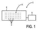
本発明による患者モニタリングシステム1は、容量性測定によるECG測定に適している。図1に図示されるように、システム1は、マトリクス3の形態で構成された複数の容量性非接触電極2を有する。電極2は、ベッド4等と一体化される。この目的のため、電極2は、好ましくは、(例えば可撓性ホイルを使用して電極構造を蒸着することにより)ベッド2と一体化される可撓性基板上の電極構造として作られるか、又は、電極2は、マトリクス3を形成するため、ベッドシーツ等に編み込まれても良い。各々の電極2は、制御ユニット5により、容量性測定を実行するために個々に選択可能である。制御ユニット5は、複数の接続線(示されていない)を介して、全ての電極2に接続される。 The patient monitoring system 1 according to the present invention is suitable for ECG measurement by capacitive measurement. As illustrated in FIG. 1, the system 1 has a plurality of
患者(示されていない)がベッド3上に位置される場合、システム1は、意図された容量性測定を実行するのに最も適した電極2を見つける。 If a patient (not shown) is positioned on the bed 3, the system 1 finds the
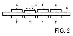
本発明の第1の実施例によると、図2に概略的に記載されるように患者の位置が決定される。患者の位置に依存して、患者に面する複数の電極は、患者によって圧力を加えられる。説明的な目的で4つの隣接した電極対が図2において図示され、各々の電極対が、患者に面する電極(対向電極)6とセンシング電極7とを有する。マトリクス3における1つの電極対のうち、患者に面する電極6'は、例えば(電極6'に向けて複数の矢印で図示される)患者の脚により圧力を加えられる。患者に面する電極6'と、関連するセンシング電極7'との間に位置される誘電体8は、圧縮され、この電極対の容量が変化する。この容量の変化は、分析ユニットのブリッジ回路により検出される。分析ユニットは、制御ユニット5の一体化された部分として備えられる。 According to a first embodiment of the invention, the position of the patient is determined as described schematically in FIG. Depending on the position of the patient, the plurality of electrodes facing the patient are pressurized by the patient. For illustrative purposes, four adjacent electrode pairs are illustrated in FIG. 2, each electrode pair having a patient-facing electrode (counter electrode) 6 and a sensing electrode 7. Of one electrode pair in the matrix 3, the electrode 6 'facing the patient is pressed by the patient's leg (illustrated by a plurality of arrows towards the electrode 6'), for example. The dielectric 8 located between the patient-facing electrode 6 'and the associated sensing electrode 7' is compressed and the capacitance of this electrode pair changes. This change in capacitance is detected by the bridge circuit of the analysis unit. The analysis unit is provided as an integrated part of the
図3に示されるように、本発明の第2の実施例に従って、患者の体9は、「対向電極」として使用され、患者は、直接誘電体8を押し下げる。再び容量の変化が、制御ユニット5の一部である分析ユニットのブリッジ回路により検出される。 As shown in FIG. 3, in accordance with a second embodiment of the present invention, the patient's
本発明の第3の実施例により、図3に示されるような構成が修正される。このため、電圧信号は、電極10に供給され、誘導された電荷が、隣接する電極11において決定される。この実施例は図4において図示される。電圧信号は、接続線を通じて制御ユニット5により電極10に供給され、誘導された電荷の決定は、好ましくは、電荷増幅器(示されていない)を使用して実行される。これらのコンポーネントのいくつか、例えば電気回路は、電極10、11付近に置かれるか、又は電極と一体化されても良い。言い換えると、コンポーネントは、マトリクス3と一体化、すなわちベッドシーツ又はベッド2に含まれても良い。制御ユニット5は、各々の電極10,11を別々にアドレス付けする。 According to the third embodiment of the present invention, the configuration as shown in FIG. 3 is modified. Thus, a voltage signal is supplied to the
測定された電荷から、2つの電極10,11間の容量が、分析ユニットにより決定される。この容量は、患者の位置にも依存し、センシング電極11に対してある距離に位置されてもよい。したがって、患者が電極と直接接触していない場合でも、患者の位置は、測定結果に影響し得る。送信された電圧信号の全てのパラメータが知られるため、センシング電極11の感度は、次の実際のECG測定の間、寄生信号をフィルタリング除去するため、「較正」され得る。好ましくは、非常に多くの又は全ての電極が、実際の測定を実行する前にこのようにテストされる。したがって、例えば信号カップリングの点で、最も良い特性を示す電極が決定され得る。 From the measured charge, the capacity between the two
この測定の構成は、次の測定の間、患者の心拍のために電気的に誘導される電荷を決定するためにも使用され得る。このように患者の心拍を測定することは、患者の(導電的な)体の存在による容量の変化のアクティブな測定に対して、交互に、又は同時に行われても良い。電極構造及び電子装置は、好ましくは、電気的ポテンシャルのリモートセンシングを可能にするとともに、非接触ECG信号を測定するため、高い入力インピーダンス、通常1Hzにおいて1013オームを供給する。言い換えると、本発明を用いた測定手順が提供され、該手順の間、電極の感度は、導電性の人間の体の存在による容量の変化を使用して較正され得る。更に、測定手順は、体のインピーダンスの量的な評価を可能にする。同じ較正方法を用いて、ECG信号の有効性が評価され得る。This measurement configuration can also be used to determine the electrically induced charge for the patient's heartbeat during the next measurement. Measuring the patient's heart rate in this way may be performed alternately or simultaneously with respect to the active measurement of the change in capacitance due to the presence of the patient's (conductive) body. The electrode structure and electronic device preferably provide a high input impedance, typically 1013 ohms at 1 Hz, to allow remote sensing of electrical potential and to measure contactless ECG signals. In other words, a measurement procedure using the present invention is provided, during which the sensitivity of the electrodes can be calibrated using the change in capacitance due to the presence of a conductive human body. Furthermore, the measurement procedure allows a quantitative assessment of body impedance. Using the same calibration method, the validity of the ECG signal can be evaluated.
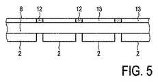
本発明の第4の実施例にしたがって、システム1は、導電性の経路の遮蔽部12を有する。遮蔽構造は、開放(opening)部13が電極2の上部のアクティブ測定部に備えられ、遮蔽材料は開放部13を取り囲むために使用されるような態様である。測定構成が対向電極6なしで使用される場合、遮蔽部12は、好ましくは図5において図示されるように、患者に面する誘電体8の側に位置される遮蔽層として設けられる。 In accordance with a fourth embodiment of the present invention, the system 1 includes a
好ましくは、上述の電極テスト手順は、マトリクス3内に構成された全ての電極2に対して実行される。各々の電極2の容量値から、患者の正確な位置が分析ユニットにより決定される。適切な電極2が決定及び(事前に)選択されている場合、実際の容量性ECG測定が実行される。適切な電極2を選択するプロセスは、好ましくは測定の種類を考慮して(上述のパラメータに従う)事前の選択及び最終的な選択を含み得る。例えば、ECG測定が実行されるべきである場合、最終的に選択されるべきである電極2は、ある相互の距離を有することを必要とする。位置のデータから、患者の四肢の位置さえも決定することができる。従って、電極2は、患者の体の適切な測定位置、例えば腕の低い側の端、又は胸部の中央に対して、患者の位置に従って好ましくは選択され得る。 Preferably, the electrode test procedure described above is performed for all the
上述のセンサ構成を持つシステム1は、生体インピーダンス測定に対しても使用され得る。この場合において、好ましくは4つの適切な電極が決定されなければならない。2つの電極は、プロービングされる体内に電流を誘導するために使用される。他の2つの電極は、プロービングされた体のインピーダンスに依存してポテンシャルの差を示す。容量性/抵抗性ネットワークの電気的パラメータの分析は、組織含量の導出を可能にする。胸部において、このことは、患者の肺における水を識別するのを助けることができる。体脂肪の分析も可能である。 The system 1 having the above sensor configuration can also be used for bioimpedance measurement. In this case, preferably four appropriate electrodes must be determined. Two electrodes are used to induce a current in the body to be probed. The other two electrodes show a potential difference depending on the impedance of the probed body. Analysis of the electrical parameters of the capacitive / resistive network allows the derivation of tissue content. In the chest, this can help identify water in the patient's lungs. Analysis of body fat is also possible.
本発明は、上述の説明的な実施例の詳細には限定されず、本発明は、本発明の要旨又は必須の特性から逸脱しない他の特定の形態において実現されても良いということは、当業者には明らかであろう。それゆえ本実施例は、全ての観点において、制限的ではなく説明的に考慮され、本発明の範囲は、上記の記載ではなく請求項により示され、請求項と等価な意味及び範囲におけるすべての変更は、それゆえ、当該請求項に含まれると意図される。更に、「有する」という言葉は、他の要素又はステップを排除せず、単数の表記は、複数を排除せず、コンピュータシステム又は他のユニットのような単一の要素は、請求項において繰り返されるいくつかの手段の機能を満足しても良い。請求項におけるいかなる参照符号も、当該請求項を制限するものとして解釈されるべきではない。 It is to be understood that the invention is not limited to the details of the illustrative embodiments described above, and that the invention may be embodied in other specific forms without departing from the spirit or essential characteristics of the invention. It will be clear to the contractor. This embodiment is therefore considered in all respects to be illustrative rather than restrictive, and the scope of the present invention is indicated by the following claims rather than the above description, and all equivalents and scope equivalent to the claims are construed. Modifications are therefore intended to be included in the claims. Further, the word “comprising” does not exclude other elements or steps, the singular number does not exclude a plurality, and a single element, such as a computer system or other unit, is repeated in the claims. It may satisfy the functions of several means. Any reference signs in the claims should not be construed as limiting the claim.
参照符号リスト
1 システム
2 電極
3 マトリクス
4 ベッド
5 制御ユニット
6 対向電極
7 センシング電極
8 誘電体
9 患者の体
10 電極
11 電極
12 遮蔽部
13 開放部Reference Code List 1
Claims (6)
Translated fromJapanese- マトリクスの形態で構成され、ベッド、椅子又はテーブルと一体化され、各々が個々に選択可能である複数の電極と、
-前記複数の電極の容量を決定することにより、前記ベッド、椅子又はテーブルにおける前記患者の位置に依存して複数の適切な電極を決定する手段と、
-前記容量性測定の種類を考慮して、複数の前記適切な電極を選択する手段と、
- 前記選択された複数の適切な電極を用いて前記容量性測定を実行する手段と、
を有する患者モニタリングシステム。A patient monitoring system for monitoringECG , EEG, EMG or bioimpedance by capacitive measurement comprising:
-A plurality of electrodes configured in the form of a matrix, integrated with a bed, chair or table, each individually selectable;
-by determining the capacity of said plurality of electrodes,and means to determine theappropriate electrode of themultiple depending on the position of the patient in the bed, chair or table,
-Means for selecting aplurality of the appropriate electrodes in view of the type of capacitive measurement ;
-Means for performing the capacitive measurement using the selected plurality of suitable electrodes;
A patient monitoring system.
各々が、前記患者に面する前記誘電体の側に位置される対向電極と、前記誘電体の反対側に位置されるセンシング電極とにより形成される複数の電極対であって、前記誘電体は、前記患者が前記ベッド、椅子又はテーブルの上に位置される場合、該患者により圧力を加えられるように構成される、複数の電極対と、
前記複数の電極対の容量を決定する手段と、
を有する、請求項1に記載の患者モニタリングシステム。A dielectric composed of an elastic structure;
Each of a plurality of electrode pairs formed by a counter electrode positioned on the side of the dielectric facing the patient and a sensing electrode positioned on the opposite side of the dielectric, wherein the dielectric is A plurality of electrode pairs configured to be pressurized by the patient when the patient is positioned on the bed, chair or table;
Means for determining a capacity of the plurality of electrode pairs;
The patient monitoring system according to claim 1, comprising:
複数の前記電極の容量を決定する手段と、
を有する、請求項1に記載の患者モニタリングシステム。When the patient is positioned on the bed, chair or table, a dielectric positioned adjacent to the plurality of electrodes in a manner facing the patient, comprising an elastic structure, wherein the patient A dielectric configured to be pressured by the patient when positioned on the bed, chair or table;
Means for determining a capacity of a plurality of said electrodes;
The patient monitoring system according to claim 1, comprising:
複数の第2電極において、誘導される電荷を決定する手段と、
を有する、請求項1に記載の患者モニタリングシステム。Means for supplying a voltage signal to the plurality of first electrodes;
Means for determining the induced charge in the plurality of second electrodes;
The patient monitoring system according to claim 1, comprising:
- マトリクスの形態で複数の電極を構成するステップであって、前記電極がベッド、椅子又はテーブルと一体化され、各々の電極が個々に選択可能である、複数の電極を構成するステップと、
-前記複数の電極の容量を決定することにより、前記ベッド、椅子又はテーブルの上の患者の位置に依存して複数の適切な電極を決定するステップと、
-前記容量性測定の種類を考慮して、複数の前記適切な電極を選択するステップと、
- 前記選択された複数の適切な電極を用いて前記容量性測定を実行するステップと、
を有する方法。A method of monitoringECG , EEG, EMG or bioimpedance by capacitive measurement comprising:
-Configuring a plurality of electrodes in the form of a matrix, wherein said electrodes are integrated with a bed, chair or table, each electrode being individually selectable, and configuring a plurality of electrodes;
-by determining the capacity of said plurality of electrodes, andLuz step to determine theappropriate electrode of themultiple depending on the patient's position on the bed, chair or table,
-Selecting a plurality of the appropriate electrodes in view of the type of capacitive measurement ;
-Performing the capacitive measurement using the selected plurality of suitable electrodes;
Having a method.
Applications Claiming Priority (3)
| Application Number | Priority Date | Filing Date | Title |
|---|---|---|---|
| EP05104933 | 2005-06-07 | ||
| EP05104933.6 | 2005-06-07 | ||
| PCT/IB2006/051753WO2006131855A2 (en) | 2005-06-07 | 2006-06-01 | Patient monitoring system and method |
Publications (2)
| Publication Number | Publication Date |
|---|---|
| JP2008541977A JP2008541977A (en) | 2008-11-27 |
| JP5253156B2true JP5253156B2 (en) | 2013-07-31 |
Family
ID=37119451
Family Applications (1)
| Application Number | Title | Priority Date | Filing Date |
|---|---|---|---|
| JP2008515339AActiveJP5253156B2 (en) | 2005-06-07 | 2006-06-01 | Patient monitoring system and method |
Country Status (5)
| Country | Link |
|---|---|
| US (1) | US9788791B2 (en) |
| EP (1) | EP1890594B1 (en) |
| JP (1) | JP5253156B2 (en) |
| CN (1) | CN101188969B (en) |
| WO (1) | WO2006131855A2 (en) |
Families Citing this family (55)
| Publication number | Priority date | Publication date | Assignee | Title |
|---|---|---|---|---|
| US9962098B2 (en) | 2006-06-02 | 2018-05-08 | Global Cardiac Monitors, Inc. | Heart monitor electrode system |
| CN101662984B (en)* | 2007-04-24 | 2013-10-30 | 皇家飞利浦电子股份有限公司 | Sensor arrangement and method for monitoring physiological parameters |
| CN101896120B (en)* | 2007-12-12 | 2012-10-10 | 皇家飞利浦电子股份有限公司 | Sleep position detection |
| CA2729873A1 (en)* | 2008-07-07 | 2010-01-14 | Heard Systems Pty Ltd | A system for sensing electrophysiological signals |
| EP2312998B1 (en)* | 2008-07-18 | 2018-12-05 | Flexcon Company, Inc. | High impedance signal detection systems and methods for use in electrocardiogram detection systems |
| DE102008033761A1 (en)* | 2008-07-18 | 2010-01-21 | Siemens Aktiengesellschaft | Medical imaging diagnostic system, particularly angiographic X-ray device, has examination table for supporting and examining patient and impedance sensors are integrated in medical imaging diagnostic system |
| JP5689798B2 (en) | 2008-08-06 | 2015-03-25 | フレクスコン カンパニー インク | Biomedical sensor system |
| US20100042012A1 (en)* | 2008-08-15 | 2010-02-18 | Karim Alhussiny | Diagnostic device for remote sensing and transmitting biophysiological signals |
| US20150201858A1 (en)* | 2008-08-15 | 2015-07-23 | Global Cardiac Monitors, Inc. | Diagnostic device for remote sensing and transmitting biophysiological signals |
| CN102137621B (en)* | 2008-08-29 | 2013-05-08 | 皇家飞利浦电子股份有限公司 | Compensation of motion artifacts in capacitive measurement of electrophysiological signals |
| US8535246B2 (en)* | 2009-04-16 | 2013-09-17 | Dm Systems, Inc. | System and method of reducing risk and/or severity of pressure ulcers |
| CA2756710C (en)* | 2009-04-27 | 2013-06-04 | Rostrum Medical Innovations Inc. | Apparatus and method for monitoring the degree of integration between the functions of the heart and the lungs, and the therapeutic success of resuscitative interventions |
| CN102970925B (en)* | 2010-07-16 | 2015-02-18 | 斯威斯托姆公开股份有限公司 | Electrode sensor and use of electrode sensor as EIT electrode |
| JP5678514B2 (en)* | 2010-08-17 | 2015-03-04 | オムロンヘルスケア株式会社 | Body fat measuring device |
| GB2489704B (en)* | 2011-04-04 | 2013-06-12 | Cardiocity Ltd | ECG mat |
| JP5432207B2 (en) | 2011-04-19 | 2014-03-05 | 東海ゴム工業株式会社 | Capacitive sensor device |
| DE102011076885B4 (en)* | 2011-06-01 | 2013-08-29 | Siemens Aktiengesellschaft | Method for controlling a medical device, device with a medical device and data carrier |
| US8781565B2 (en) | 2011-10-04 | 2014-07-15 | Qualcomm Incorporated | Dynamically configurable biopotential electrode array to collect physiological data |
| KR101940492B1 (en)* | 2012-07-26 | 2019-04-10 | 한국전자통신연구원 | Sensor for measuring tilt base on electronic textile and method thereof |
| TWI498100B (en)* | 2012-08-28 | 2015-09-01 | Chen Yu Han | Sensing pad of physiological electrical signal and sensing mattress of using the same |
| US9378655B2 (en) | 2012-12-03 | 2016-06-28 | Qualcomm Incorporated | Associating user emotion with electronic media |
| JP5986008B2 (en)* | 2013-02-08 | 2016-09-06 | 日本電信電話株式会社 | Method for manufacturing conductive fabric and method for manufacturing biological signal measuring apparatus |
| JP2016198121A (en)* | 2013-09-27 | 2016-12-01 | アルプス電気株式会社 | Biological information detection device and seat with biological information detection device |
| CZ308222B6 (en)* | 2013-10-08 | 2020-03-11 | Linet Spol. S. R. O. | Device for contactless monitoring of vital patient signs |
| EP3073909B1 (en)* | 2013-11-25 | 2021-10-27 | Koninklijke Philips N.V. | Electrocardiography monitoring system and method |
| FR3023711B1 (en)* | 2014-07-16 | 2016-08-19 | Ecometering | IMPROVED MATTRESS |
| SG11201610065UA (en) | 2014-09-23 | 2016-12-29 | Rr Sequences Inc | Contactless electric cardiogram system |
| EP3000385A1 (en)* | 2014-09-25 | 2016-03-30 | University of Maribor | Apparatus and method for measuring bio-potentials of a person |
| US11284808B2 (en) | 2014-10-11 | 2022-03-29 | Linet Spol. S.R.O. | Device and method for measurement of vital functions, including intracranial pressure, and system and method for collecting data |
| US10638969B2 (en) | 2014-11-10 | 2020-05-05 | Walgreens Health Solutions, LLC | Wireless pressure ulcer alert methods and systems therefor |
| US12114995B2 (en) | 2014-11-10 | 2024-10-15 | Walgreen Health Solutions, Llc | Wireless pressure-sensitive dressing assemblies and wireless monitoring systems equipped therewith |
| CN104411150B (en)* | 2014-11-28 | 2018-08-14 | 深圳诺康医疗设备股份有限公司 | A kind of mattress |
| US9808202B2 (en)* | 2014-11-28 | 2017-11-07 | Shenzhen Novocare Medical Devices Co, INC | Mattress for measuring physiological parameters of heart |
| JP6766052B2 (en) | 2015-01-27 | 2020-10-07 | アップル インコーポレイテッドApple Inc. | Systems and methods for determining sleep quality |
| FR3039979B1 (en)* | 2015-08-11 | 2017-09-01 | Bioserenity | METHOD FOR MEASURING AN ELECTROPHYSIOLOGICAL PARAMETER USING A CAPACITIVE ELECTRODE SENSOR WITH CONTROLLED CAPACITY |
| EP3361978B1 (en) | 2015-10-16 | 2025-07-02 | Dalhousie University | Systems for monitoring patient motion via capacitive position sensing |
| CN105853083A (en)* | 2016-04-13 | 2016-08-17 | 苏州海神联合医疗器械有限公司 | Mobile sickbed for electromyography examination and electromyography examination method |
| CN105708454B (en)* | 2016-04-13 | 2018-08-24 | 苏州海神联合医疗器械有限公司 | Checking with EMG method single rack vehicle and checking with EMG method method |
| EP3469323A4 (en) | 2016-06-08 | 2020-03-18 | The University of British Columbia | Surface sensor arrays using ionically conducting material |
| PL3474732T3 (en) | 2016-06-22 | 2024-01-29 | Linet Spol. S.R.O. | Device for monitoring patient's vital functions comprising a piezoelectric transducer and a measuring capacitor |
| DE102016112391A1 (en)* | 2016-07-06 | 2018-01-25 | Capical Gmbh | treatment table |
| US10512432B2 (en)* | 2016-08-12 | 2019-12-24 | Apple Inc. | Vital signs monitoring system |
| US10670429B2 (en) | 2017-02-09 | 2020-06-02 | The University Of British Columbia | Capacitive bending sensors |
| US10831319B2 (en) | 2017-02-09 | 2020-11-10 | The University Of British Columbia | Cluster sensor |
| CN107788968B (en)* | 2017-03-07 | 2020-07-17 | 中南大学 | A non-contact multi-lead ECG monitoring system based on array capacitive electrodes |
| WO2018217585A1 (en) | 2017-05-22 | 2018-11-29 | Apple Inc. | Multi-element piezo sensors for physiological measurements |
| JP7217445B2 (en)* | 2018-10-10 | 2023-02-03 | 日本電子精機株式会社 | Sleep posture measurement device and sleep posture measurement method |
| DE102018221960B3 (en)* | 2018-12-17 | 2020-03-26 | Siemens Healthcare Gmbh | Detection device and method for detecting a breathing movement, computer program, computer-readable storage medium and medical device |
| TWI715022B (en)* | 2019-04-29 | 2021-01-01 | 宏碁股份有限公司 | Smart care mattress and method for detecting the physiological state of user |
| CN111956229B (en)* | 2019-05-20 | 2023-05-23 | 宏碁股份有限公司 | Intelligent care mattress and method for detecting physiological state of user |
| WO2021195332A1 (en) | 2020-03-25 | 2021-09-30 | Flexcon Company, Inc. | Isotropic non-aqueous electrode sensing material |
| DE102020216602A1 (en)* | 2020-12-30 | 2022-06-30 | Siemens Healthcare Gmbh | Image-based sensor selection in the capacitive measurement of bioelectrical signals |
| JP2022181162A (en)* | 2021-05-25 | 2022-12-07 | 富士フイルム株式会社 | Information processing device, measurement system, information processing method, and information processing program |
| KR102617057B1 (en)* | 2022-12-28 | 2023-12-28 | 럭스나인 주식회사 | Top for electrocardiogram measurement and electrocardiogram data relay device using the same |
| KR102617061B1 (en)* | 2022-12-30 | 2023-12-28 | 럭스나인 주식회사 | Top for electrocardiogram measurement and electrocardiogram data relay device using the same |
Family Cites Families (29)
| Publication number | Priority date | Publication date | Assignee | Title |
|---|---|---|---|---|
| FI59718C (en) | 1979-03-13 | 1981-10-12 | Instrumentarium Oy | FOERFARANDE INOM LAEKARVETENSKAPEN FOER OEVERVAKNING OCH / ELLER REGISTRERING AV EN PAO EN SAENG LIGGANDE PERSONS T EX EN PATIENTS KROPPSROERELSER |
| US4474185A (en)* | 1982-05-12 | 1984-10-02 | Diamond Donald A | Body movement detector |
| US4757825A (en)* | 1985-10-31 | 1988-07-19 | Diamond Research Group, Inc. | Cardio-pulmonary activity monitor |
| JPS62164435A (en)* | 1986-01-14 | 1987-07-21 | 斉藤 元章 | Apparatus for detecting living body information |
| US5010772A (en)* | 1986-04-11 | 1991-04-30 | Purdue Research Foundation | Pressure mapping system with capacitive measuring pad |
| US4827763A (en)* | 1986-04-11 | 1989-05-09 | Purdue Research Foundation | Pressure mapping system with capacitive measuring pad |
| ATE114441T1 (en)* | 1989-09-07 | 1994-12-15 | Siemens Ag | METHOD AND CIRCUIT ARRANGEMENT FOR MONITORING SEVERAL ELECTRODE AREAS OF THE NEUTRAL ELECTRODE OF AN H.F. SURGICAL DEVICE. |
| CN2084800U (en)* | 1991-03-16 | 1991-09-18 | 广州无线电研究所 | Electrocardiosignal monitor |
| US5449002A (en)* | 1992-07-01 | 1995-09-12 | Goldman; Robert J. | Capacitive biofeedback sensor with resilient polyurethane dielectric for rehabilitation |
| JPH0838437A (en) | 1994-05-25 | 1996-02-13 | Hiroshi Motoyama | Living body surface potential measuring device and diagnostic device |
| JP3564878B2 (en) | 1996-07-04 | 2004-09-15 | 松下電器産業株式会社 | Biological signal detection device |
| US6778090B2 (en)* | 1996-09-04 | 2004-08-17 | Paul Newham | Modular system for monitoring the presence of a person using a variety of sensing devices |
| US6546813B2 (en) | 1997-01-08 | 2003-04-15 | The Trustees Of Boston University | Patient monitoring system employing array of force sensors on a bedsheet or similar substrate |
| US6280392B1 (en)* | 1998-07-29 | 2001-08-28 | Denso Corporation | Infant condition monitoring system and method using load cell sensor sheet |
| JP3820811B2 (en) | 1999-08-02 | 2006-09-13 | 株式会社デンソー | Respiratory system disease monitoring device |
| US6454705B1 (en) | 1999-09-21 | 2002-09-24 | Cardiocom | Medical wellness parameters management system, apparatus and method |
| JP2001299712A (en)* | 2000-04-19 | 2001-10-30 | Advanced Medical Kk | Long-time biological monitor |
| JP2001340318A (en)* | 2000-05-31 | 2001-12-11 | Secom Co Ltd | Capacitance measuring device and respiratory measuring device |
| DE60011445D1 (en) | 2000-11-28 | 2004-07-15 | St Microelectronics Srl | Textile-type capacitive pressure sensor and method for imaging the pressure exerted on points on a surface of a flexible and flexible object, in particular a sail |
| US6753969B2 (en)* | 2001-03-29 | 2004-06-22 | Geogia Tech Research Corporation | Microinterferometer for measuring distance with improved sensitivity |
| JP3821061B2 (en)* | 2002-06-27 | 2006-09-13 | 株式会社デンソー | Respiration monitor device |
| JP3823887B2 (en)* | 2002-06-27 | 2006-09-20 | 株式会社デンソー | Apnea syndrome testing device |
| US6932774B2 (en)* | 2002-06-27 | 2005-08-23 | Denso Corporation | Respiratory monitoring system |
| EP1572292B1 (en)* | 2002-10-31 | 2010-09-29 | Medtronic, Inc. | Method and device for applying filter information to identify combinations of electrodes |
| WO2005032447A2 (en)* | 2003-08-22 | 2005-04-14 | Foster-Miller, Inc. | Physiological monitoring garment |
| JP3960298B2 (en)* | 2003-11-19 | 2007-08-15 | 株式会社デンソー | Sleeping and posture detection device |
| JP4141426B2 (en)* | 2004-03-29 | 2008-08-27 | 三洋電機株式会社 | Capacitive pressure sensor and heart rate / respiration measurement device using the same |
| US7119705B2 (en)* | 2004-10-30 | 2006-10-10 | Delphi Technologies, Inc. | Shielded capacitive load cell apparatus responsive to weight applied to a vehicle seat |
| US7935061B1 (en)* | 2006-05-09 | 2011-05-03 | David Breed | Method and apparatus for monitoring physiological conditions |
- 2006
- 2006-06-01JPJP2008515339Apatent/JP5253156B2/enactiveActive
- 2006-06-01WOPCT/IB2006/051753patent/WO2006131855A2/ennot_activeApplication Discontinuation
- 2006-06-01EPEP06756035.9Apatent/EP1890594B1/enactiveActive
- 2006-06-01USUS11/915,751patent/US9788791B2/enactiveActive
- 2006-06-01CNCN2006800198887Apatent/CN101188969B/enactiveActive
Also Published As
| Publication number | Publication date |
|---|---|
| EP1890594A2 (en) | 2008-02-27 |
| WO2006131855A3 (en) | 2007-02-15 |
| EP1890594B1 (en) | 2014-11-19 |
| WO2006131855A2 (en) | 2006-12-14 |
| CN101188969B (en) | 2010-09-29 |
| US20080208063A1 (en) | 2008-08-28 |
| US9788791B2 (en) | 2017-10-17 |
| JP2008541977A (en) | 2008-11-27 |
| CN101188969A (en) | 2008-05-28 |
Similar Documents
| Publication | Publication Date | Title |
|---|---|---|
| JP5253156B2 (en) | Patient monitoring system and method | |
| JP5208749B2 (en) | Hydration status monitoring | |
| KR102094292B1 (en) | System or method for detecting moisture in absorbent articles | |
| CN101896120B (en) | Sleep position detection | |
| AU2008241356B2 (en) | Monitoring system and probe | |
| JP5372768B2 (en) | measuring device | |
| FI120716B (en) | A method for measuring and analyzing the movements of a human or animal using audio signals | |
| Arcelus et al. | Design of a capacitive ECG sensor for unobtrusive heart rate measurements | |
| CN107205678A (en) | Contactless electrocardiogram system | |
| JP5970476B2 (en) | Determination of organizational quantity indicators | |
| Rahal et al. | A comparison study of electrodes for neonate electrical impedance tomography | |
| JP2006271978A (en) | Method and electric field mattress for monitoring sleep behavior | |
| AU2015277068B2 (en) | Detection and measurement of body part movement using capacitive sensors and inertial sensing systems | |
| US20170156640A1 (en) | System and method for detection and measurement of body part movement using capacitive sensors and inertial sensing systems | |
| JP7731889B2 (en) | Detection system and method for capacitively coupled electrophysiological detection with estimation of electrode-to-skin coupling - Patent Application 20070122999 | |
| CN207012184U (en) | Ecg signal acquiring pad | |
| JP2023530283A (en) | Edema detection | |
| Savchuk | DEVELOPMENT OF A MODEL OF ELECTRIC IMPEDANCE IN THE CONTACT BETWEEN THE SKIN AND A CAPACITIVE ACTIVE ELECTRODE WHEN MEASURING ELECTROCARDIOGRAM IN COMBUSTIOLOGY. | |
| JP7281763B2 (en) | SENSOR DEVICE, SIGNAL ANALYSIS SYSTEM AND SIGNAL ANALYSIS METHOD | |
| CN108577882A (en) | A kind of health control stethoscope of monitoring sweat and humidity of skin | |
| Kim et al. | A homecare in-bed hardware system for precise real-time ECG and HRV monitoring with layered clothing | |
| CN106580311A (en) | Electrocardiogram signal acquisition pad | |
| SG183589A1 (en) | Conductive fabric based system and method for sensing or monitoring physiological parameters |
Legal Events
| Date | Code | Title | Description |
|---|---|---|---|
| A621 | Written request for application examination | Free format text:JAPANESE INTERMEDIATE CODE: A621 Effective date:20090529 | |
| A131 | Notification of reasons for refusal | Free format text:JAPANESE INTERMEDIATE CODE: A131 Effective date:20111101 | |
| A601 | Written request for extension of time | Free format text:JAPANESE INTERMEDIATE CODE: A601 Effective date:20120125 | |
| A602 | Written permission of extension of time | Free format text:JAPANESE INTERMEDIATE CODE: A602 Effective date:20120201 | |
| A521 | Request for written amendment filed | Free format text:JAPANESE INTERMEDIATE CODE: A523 Effective date:20120419 | |
| A131 | Notification of reasons for refusal | Free format text:JAPANESE INTERMEDIATE CODE: A131 Effective date:20121206 | |
| A521 | Request for written amendment filed | Free format text:JAPANESE INTERMEDIATE CODE: A523 Effective date:20130228 | |
| TRDD | Decision of grant or rejection written | ||
| A01 | Written decision to grant a patent or to grant a registration (utility model) | Free format text:JAPANESE INTERMEDIATE CODE: A01 Effective date:20130321 | |
| A61 | First payment of annual fees (during grant procedure) | Free format text:JAPANESE INTERMEDIATE CODE: A61 Effective date:20130416 | |
| R150 | Certificate of patent or registration of utility model | Ref document number:5253156 Country of ref document:JP Free format text:JAPANESE INTERMEDIATE CODE: R150 Free format text:JAPANESE INTERMEDIATE CODE: R150 | |
| FPAY | Renewal fee payment (event date is renewal date of database) | Free format text:PAYMENT UNTIL: 20160426 Year of fee payment:3 | |
| R250 | Receipt of annual fees | Free format text:JAPANESE INTERMEDIATE CODE: R250 | |
| R250 | Receipt of annual fees | Free format text:JAPANESE INTERMEDIATE CODE: R250 | |
| R250 | Receipt of annual fees | Free format text:JAPANESE INTERMEDIATE CODE: R250 | |
| R250 | Receipt of annual fees | Free format text:JAPANESE INTERMEDIATE CODE: R250 | |
| R250 | Receipt of annual fees | Free format text:JAPANESE INTERMEDIATE CODE: R250 | |
| R250 | Receipt of annual fees | Free format text:JAPANESE INTERMEDIATE CODE: R250 | |
| R250 | Receipt of annual fees | Free format text:JAPANESE INTERMEDIATE CODE: R250 | |
| R250 | Receipt of annual fees | Free format text:JAPANESE INTERMEDIATE CODE: R250 | |
| R250 | Receipt of annual fees | Free format text:JAPANESE INTERMEDIATE CODE: R250 | |
| R250 | Receipt of annual fees | Free format text:JAPANESE INTERMEDIATE CODE: R250 |