JP5250653B2 - Endoscopic imaging apparatus and endoscope - Google Patents
Endoscopic imaging apparatus and endoscopeDownload PDFInfo
- Publication number
- JP5250653B2 JP5250653B2JP2011074277AJP2011074277AJP5250653B2JP 5250653 B2JP5250653 B2JP 5250653B2JP 2011074277 AJP2011074277 AJP 2011074277AJP 2011074277 AJP2011074277 AJP 2011074277AJP 5250653 B2JP5250653 B2JP 5250653B2
- Authority
- JP
- Japan
- Prior art keywords
- signal cable
- section
- reinforcing frame
- imaging device
- lens barrel
- Prior art date
- Legal status (The legal status is an assumption and is not a legal conclusion. Google has not performed a legal analysis and makes no representation as to the accuracy of the status listed.)
- Active
Links
Images


Landscapes
- Endoscopes (AREA)
- Instruments For Viewing The Inside Of Hollow Bodies (AREA)
Description
Translated fromJapanese本発明は、内視鏡用撮像装置及び内視鏡に関するものである。 The present invention relates to an endoscope imaging apparatus and an endoscope.
内視鏡は、例えば被検者の体内に挿入される挿入部を有する。この挿入部は、先端から順に、先端硬質部、湾曲部、軟性部となっている。そして、先端硬質部の先端面には、観察窓、照明窓、鉗子出口、送気・送水ノズルがある。また、先端硬質部の内面には、観察窓に対応した位置で撮像装置が、照明窓に対応した位置でライトガイドがそれぞれ取り付けられている。湾曲部は、複数の節輪ユニットを連結して構成されており、ワイヤ操作によって先端硬質部を所望の方向に向けることができる。軟性部は、被検体の所望の観察部位に先端硬質部を到達させるために、1m〜2m程度の長さとなっている。 An endoscope has an insertion part inserted in the body of a subject, for example. The insertion portion is a tip hard portion, a bending portion, and a soft portion in order from the tip. The distal end surface of the distal end hard portion includes an observation window, an illumination window, a forceps outlet, and an air / water feeding nozzle. Further, on the inner surface of the distal end hard part, an imaging device is attached at a position corresponding to the observation window, and a light guide is attached at a position corresponding to the illumination window. The bending portion is configured by connecting a plurality of node ring units, and the distal end hard portion can be directed in a desired direction by a wire operation. The soft part has a length of about 1 m to 2 m in order to allow the distal end hard part to reach a desired observation site of the subject.
撮像装置は、レンズやプリズム等の複数個の光学部品からなる光学系と、この光学系によって結像された光学画像を撮像信号に光電変換するCCD等の固体撮像素子とを有する。固体撮像素子はフレキシブル基板やサブ基板などを介して信号ケーブルに接続される。また、フレキシブル基板やサブ基板には固体撮像素子を駆動するために電子部品が実装されている。撮像装置からの信号は、フレキシブル基板やサブ基板、信号ケーブルを介して画像処理装置に送られる。画像処理装置では信号を画像処理して、モニタに病変等の画像を表示する。 The imaging apparatus includes an optical system including a plurality of optical components such as lenses and prisms, and a solid-state imaging element such as a CCD that photoelectrically converts an optical image formed by the optical system into an imaging signal. The solid-state imaging device is connected to a signal cable via a flexible substrate, a sub substrate, or the like. In addition, electronic components are mounted on the flexible substrate and the sub-substrate to drive the solid-state imaging device. A signal from the imaging apparatus is sent to the image processing apparatus via a flexible substrate, a sub substrate, and a signal cable. The image processing apparatus performs image processing on the signal and displays an image such as a lesion on the monitor.
撮像装置からの信号を画像処理装置に送る信号ケーブルは、複合多芯ケーブルから構成されている。この信号ケーブルは、挿入部の全長にわたって挿通されているので、挿入部がループされたり湾曲されたりする度に、強く押し引きされる。このため、基板の接合部から信号ケーブルが剥離する場合がある。 A signal cable for sending a signal from the imaging device to the image processing device is composed of a composite multi-core cable. Since the signal cable is inserted through the entire length of the insertion portion, the signal cable is strongly pushed and pulled each time the insertion portion is looped or curved. For this reason, a signal cable may peel from the junction part of a board | substrate.
このような剥離を回避するため、種々の提案がなされている。例えば、特許文献1記載の内視鏡では、フレキシブル基板の一端側に信号ケーブルが半田付けされるとともに、その半田付けされた信号ケーブルを囲むようにフレキシブル基板がコの字状に折り曲げられ、その周囲をシールドテープと絶縁テープによって被覆され、この内部空間にエポキシ系の接着剤が充填されて変形しないように固められている。さらに、信号ケーブルが固定された側の回路基板は、押さえ板を介して、固定ねじによって連結筒に固定されているため、信号ケーブルが強く押し引きされても、回路基板は動かず、信号ケーブルから回路基板に加わるねじれや傾きの力も、可撓性のある回路基板で吸収されて、固体撮像素子及び対物光学系には伝わらない。 In order to avoid such peeling, various proposals have been made. For example, in the endoscope described in
特許文献2記載の撮像装置では、フレキシブル基板と信号ケーブルの接続部は封止材で覆い固められている。 In the imaging device described in Patent Document 2, the connection portion between the flexible substrate and the signal cable is covered and sealed with a sealing material.
特許文献3記載の撮像装置は、固体撮像素子及びフレキシブル基板の電子部品実装部を収容する補強枠を備え、この補強枠の内側に接着剤を充填している。さらに、フレキシブル基板に半田付けされた信号ケーブルの先端部分と補強枠とを熱収縮チューブで覆い、この内側に接着剤を充填して密封している。 The imaging device described in
特許文献1記載の撮像装置では、回路基板を固定ねじによって連結筒に固定するという煩雑な作業が必要となるという欠点がある。特許文献2記載の撮像装置では、信号ケーブルが押し引きされる力は、フレキシブル基板との接合部やフレキシブル基板に伝わる。フレキシブル基板に伝わった力は、信号ケーブルとフレキシブル基板との半田付け部やフレキシブル基板と固体撮像素子との接合部等にかかることになり、これらのいずれか弱いところに剥離や破損が生じる懸念がある。 The imaging device described in
特許文献3記載の撮像装置では、固体撮像素子を補強枠の内部に収納する関係上、固体撮像素子のサイズによって補強枠のサイズが影響を受ける。内視鏡への要求も高画質化、細径化、オートクレーブ対応など多様化しており、それに伴い固体撮像素子及びその周辺の部品も多様化/複雑化している。固体撮像素子及びその周辺部品に機能が増えることで大型化すると、これをすべて収納する補強枠も大型化するため、内視鏡挿入部の先端硬質部の径が太くなり、患者の負担が増加するという欠点がある。 In the imaging apparatus described in
また、上記各特許文献記載の撮像装置では、挿入部内における信号ケーブルの位置を規定していないため、信号ケーブルが強く押し引きされた場合に、内蔵物の配列乱れや、他の部材との干渉が発生する懸念がある。内蔵物の配列乱れや他の部材との干渉は、信号ケーブルの破断や接合部の剥離の発生を招き、耐久性が低下するという欠点がある。 In addition, the image pickup apparatus described in each of the above patent documents does not define the position of the signal cable in the insertion portion. Therefore, when the signal cable is strongly pushed and pulled, the built-in components are disturbed or interfere with other members. There is a concern that will occur. Disturbances in the arrangement of built-in objects and interference with other members cause the signal cable to be broken and the joints to be peeled off, resulting in a drawback that durability is lowered.
本発明は、上記課題を鑑みてなされたものであり、信号ケーブルが強く押し引きされた場合でも、内蔵物の配列乱れ、及び他の部材との干渉を無くして、信号ケーブルの破断や,信号ケーブルの素線と基板の接合部の剥離の発生を抑えることができ、しかも先端硬質部の径を細くすることで患者への負担が軽減可能な内視鏡用撮像装置及び内視鏡を提供することを目的とする。 The present invention has been made in view of the above problems, and even when the signal cable is strongly pushed and pulled, the arrangement of the built-in components and interference with other members are eliminated, and the signal cable is broken or the signal is broken. Provided is an endoscope imaging device and endoscope that can suppress the occurrence of peeling of the cable strand and the joint between the board and reduce the burden on the patient by reducing the diameter of the hard tip. The purpose is to do.
本発明の内視鏡用撮像装置は、レンズ鏡筒と、レンズ鏡筒を介して結像される光学画像を光電変換する固体撮像素子と、固体撮像素子が取り付けられる基板と、複数の素線及びこれを覆う外皮からなり、素線が基板に電気的に接続されている信号ケーブルと、底板部の両端に側板部が連接されて横断面がU字形であり、底板部の上方に開口部を有する樋状部材であって、一端がレンズ鏡筒に他端が信号ケーブルの外皮にそれぞれ固定されており、レンズ鏡筒の光軸と信号ケーブルの中心軸とをオフセットさせ、前記レンズ鏡筒と前記信号ケーブルとを段違いにする補強枠と、を備える。An endoscope imaging apparatus according to the present invention includes a lens barrel, a solid-state imaging device that photoelectrically converts an optical image formed through the lens barrel, a substrate to which the solid-state imaging device is attached, and a plurality of strands. And a signal cable having a sheath covering the element, the element wire being electrically connected to the substrate, a side plate portion connected to both ends ofthe bottom plate portion, and a U-shaped cross section, and an opening above the bottom plate portion The lens barrel having one end fixed to the lens barrel and the other end fixed to the outer sheath of the signal cable, offsetting the optical axis of the lens barrel and the center axis of the signal cable, And a reinforcing frame that makes the signal cable uneven .
また、本発明の内視鏡用撮像装置は、レンズ鏡筒と、レンズ鏡筒を保持する保持部材と、レンズ鏡筒を介して結像される光学画像を光電変換する固体撮像素子と、固体撮像素子が取り付けられる基板と、複数の素線及びこれを覆う外皮からなり、素線が基板に電気的に接続されている信号ケーブルと、底板部の両端に側板部が連接されて横断面がU字形であり、底板部の上方に開口部を有する樋状部材であって、一端が保持部材に他端が信号ケーブルの外皮にそれぞれ固定されており、レンズ鏡筒の光軸と信号ケーブルの中心軸とをオフセットさせ、前記レンズ鏡筒と前記信号ケーブルとを段違いにする補強枠と、を備える。An endoscope imaging apparatus according to the present invention includes a lens barrel, a holding member that holds the lens barrel, a solid-state imaging device that photoelectrically converts an optical image formed through the lens barrel, and a solid state A substrate to which the image sensor is attached, a plurality of strands and a sheath covering the strands, a signal cable in which the strands are electrically connected to the substrate, and a side plate portion connected to both ends of the bottom plate portion and a cross section A U-shaped member having an opening above the bottom plate portion, one end fixed to the holding member and the other end fixed to the outer sheath of the signal cable, and the optical axis of the lens barrel and the signal cable A reinforcing frame that offsets the central axis and makes the lens barrel and the signal cable in a different step.
補強枠は、補強枠本体と、この補強枠本体に連続し、後方に向かうに従い樋方向に直交する横断面の断面積が次第に小さくなるように絞られる絞り部と、この絞り部の後端で、信号ケーブルの外皮が入れられるケーブル固定部とを有し、絞り部によりレンズ鏡筒の光軸と信号ケーブルの中心軸とがオフセットされ、基板は補強枠本体の開口を覆うことが好ましい。また、基板は、固体撮像素子が取り付けられるメイン基板とこのメイン基板とは別体で形成され、周辺電子部材が取り付けられるサブ基板とから構成され、メイン基板は、補強枠本体の開口部を覆うように取り付けられ、サブ基板は補強枠内に内蔵されることが好ましい。また、補強枠内に充填され、ケーブル素線を一体化する接着剤を有することが好ましい。The reinforcing frame includes a reinforcing frame main body, a throttle portion that is continuous with the reinforcing frame main body, and is narrowed so that a cross-sectional area of a cross section perpendicular to the flange direction gradually decreases toward the rear, and a rear end of the throttle portion. It is preferable that the optical fiber of the lens barrel and the center axis of the signal cable are offset by the diaphragm portion, and the substrate covers the opening of the reinforcing frame body. Further, the substrate is composed of a main substrate to which the solid-state imaging device is attached and a sub-substrate that is formed separately from the main substrate and to which peripheral electronic members are attached. The main substrate covers the opening of the reinforcing frame body. The sub-board is preferably built in the reinforcing frame. Moreover, it is preferable to have an adhesive that fills the reinforcing frame and integrates the cable strands.
本発明の内視鏡は、上記の内視鏡用撮像装置が取り付けられる先端硬質部を有する内視鏡であって、先端硬質部の先端面は、鉗子出口、観察窓、照明窓、送気・送水ノズルを有し、先端硬質部内には、観察窓に対応する位置に内視鏡用撮像装置が取り付けられ、照明窓に対応する位置にライトガイドが取り付けられ、鉗子出口に鉗子チャンネルが取り付けられ、送気・送水ノズルに、送気チューブ及び送水チューブが取り付けられ、補強枠を用いて、挿入部の中心軸に対し、鉗子チャンネルの対角位置に信号ケーブルを位置決めする。An endoscope of the present invention is an endoscope having a hard tip portion to which the above-described endoscope imaging device is attached, and a tip surface of the hard tip portion has a forceps outlet, an observation window, an illumination window, and an air supply -It has a water supply nozzle, an endoscope imaging device is attached to the position corresponding to the observation window, a light guide is attached to the position corresponding to the illumination window, and a forceps channel is attached to the forceps outlet The air supply tube and the water supply tube are attached to the air supply / water supply nozzle, and the signal cable is positioned at the diagonal position of the forceps channel with respect to the central axis of the insertion portion using thereinforcing frame .
なお、先端硬質部に続いて湾曲部を有し、湾曲部は、複数の節輪ユニットを連結ピンで連結し、連結ピンに操作ワイヤを通して上下左右に湾曲自在に構成され、湾曲部の中心軸に直交する横断面における湾曲部内を、複数の節輪ユニットの中心軸に対し点対称な1対の連結ピンを繋ぐ仮想線によって90°間隔で4区画に分け、このうちの第1区間に鉗子チャンネルを位置させ、この第1区画に隣接する第2区画に第1ライトガイドを位置させ、第2区画に隣接する第3区画に信号ケーブル及び第2ライトガイドを位置させ、第3区画に隣接する第4区画に送気チューブ・送水チューブを位置させることが好ましい。また、第3区画の第2ライトガイドと、第4区画の送気チューブ・送水チューブを入れ替えて、第1区間に鉗子チャンネル、第2区画に第1ライトガイド、第3区画に信号ケーブル及び送気チューブ、送水チューブ、第4区画に第2ライトガイドを位置させることが好ましい。The bending portion has a bending portion subsequent to the distal end hard portion, and the bending portion is configured such that a plurality of node ring units are connected by a connecting pin, and can be bent vertically and horizontally through an operation wire to the connecting pin. Is divided into four sections at 90 ° intervals by a virtual line that connects a pair of connecting pins that are point-symmetric with respect to the central axis of a plurality of node ring units. The channel is positioned, the first light guide is positioned in the second section adjacent to the first section, the signal cable and the second light guide are positioned in the third section adjacent to the second section, and adjacent to the third section. It is preferable to position the air supply tube / water supply tube in the fourth section. In addition,the second light guide inthe third section and the air / water supply tube in the fourth section are exchanged, the forceps channelin the first section, the first light guide inthe second section, the signal cable and the transmission in the third section. The second light guide is preferablypositioned in the air tube, the water supply tube, and the fourth section.
本発明によれば、補強枠によりレンズ鏡筒の光軸に対して信号ケーブルの中心軸をオフセットさせ、前記レンズ鏡筒と前記信号ケーブルとを段違いに構成するため、挿入部内で信号ケーブルが他の内蔵物に干渉することの無い位置に位置決めすることができる。したがって、他の部材との干渉がなくなる他、挿入部内で各内蔵物が所定の配列エリアから移動してしまう配列乱れが抑えられる。また、他の部材の干渉や配列乱れに起因する信号ケーブルの破断や、接合部剥離の発生が無くなり、耐久性が向上する。According to the present invention, the central axis of the signal cable is offset by thereinforcing frame with respect to the optical axis of thelens barrel, and the lens barrel and the signal cable are configured in a different step. It can be positioned at a position where it does not interfere with the built-in components. Accordingly, interference with other members is eliminated, and the arrangement disorder in which each built-in object moves from a predetermined arrangement area in the insertion portion is suppressed.In addition, the signal cable is not broken or the joint is not peeled off due to interference of other members or arrangement disorder, and durability is improved.
補強枠を用いて、挿入部の中心軸に対し、鉗子チャンネルの対角位置に信号ケーブルを位置決めすることにより、湾曲部が湾曲しても補強枠によるオフセット保持効果が発揮され、鉗子チャンネルと信号ケーブルとの位置関係が崩れることが少なくなる。したがって、湾曲による信号ケーブルのストレスを少なくすることができ、信号ケーブルの破断防止や、耐久性の向上が図れる。また、補強枠による各チューブの緩い位置規制効果によって、挿入部の各区画内で各チューブ類のクリアランスを確保したバランスの良い配置となり、バランス不良に起因する湾曲動作時の各チューブ類の摺動抵抗の増加も抑えられる。By positioning the signal cable at the diagonal position of the forceps channel with respect to the central axis of the insertion portion using thereinforcing frame , the offset holding effect is exerted by thereinforcing frame even if the bending portion is bent. The positional relationship with the cable is less likely to collapse. Therefore, the stress of the signal cable due to bending can be reduced, and the signal cable can be prevented from being broken and the durability can be improved. Also, due to the loose position restriction effect of each tube by thereinforcing frame , it becomes a well-balanced arrangement ensuring the clearance of each tube within each section of the insertion part, and the sliding of each tube during bending operation due to poor balance An increase in resistance can also be suppressed.
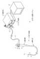
図1において、電子内視鏡システム10は、電子内視鏡11、プロセッサ装置12、光源装置13からなる。電子内視鏡11は、被検体(患者)内に挿入される可撓性の挿入部14と、挿入部14の基端部分に連設された操作部15と、プロセッサ装置12および光源装置13に接続されるコネクタ16と、操作部15、コネクタ16間を繋ぐユニバーサルコード17とを有する。 In FIG. 1, an electronic endoscope system 10 includes an
操作部15の先端側には、鉗子口18が設けられている。鉗子口18には、電気メス等の処置具が挿通される。鉗子口18は、挿入部14内の鉗子チャンネル19(図2参照)を通して、先端面14aの鉗子出口20(図2および図3参照)に連通している。 A
操作部15は、アングルノブ21、送気・送水ボタン22、吸引ボタン23、レリーズボタンなどの各種操作部材を備えている。アングルノブ21は、回転操作によって挿入部14の先端硬質部31を上下左右方向に湾曲させる。送気・送水ボタン22は、押圧操作によって送気・送水ノズル43(図3参照)からエアーまたは水を噴出させる。吸引ボタン23は、押圧操作によって、体内の液体や組織等の被吸引物を鉗子出口20から吸引する。レリーズボタンは、押圧操作によって観察画像を静止画記録する。 The operation unit 15 includes various operation members such as an
プロセッサ装置12は、光源装置13と電気的に接続され、電子内視鏡システム10の動作を統括的に制御する。プロセッサ装置12は、ユニバーサルコード17や挿入部14内に挿通された信号ケーブル25(図2参照)を介して電子内視鏡11に給電を行い、先端硬質部31に搭載された撮像装置26(図2参照)の駆動を制御する。また、プロセッサ装置12は、信号ケーブル25を介して撮像装置26からの信号を受信し、各種処理を施して画像データを生成する。プロセッサ装置12にはモニタ27が接続されている。モニタ27は、プロセッサ装置12からの画像データに基づき観察画像を表示する。 The processor device 12 is electrically connected to the light source device 13 and comprehensively controls the operation of the electronic endoscope system 10. The processor device 12 supplies power to the
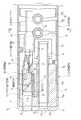
挿入部14は、先端面14aから順に、先端硬質部31、湾曲部32、及び軟性部33となっている。図2に示すように、先端硬質部31は、硬質樹脂製の先端部本体35に、軟質樹脂製の先端キャップ30を被せ、先端部本体35とこれに続く湾曲部32の金属製先端筒37をチューブ36により被覆して構成される。湾曲部32は、先端筒37、複数の関節用節輪38a,38b,38c,・・・を連結ピン39で連結した節輪ユニット38から構成され、ピン結合部分が所定角度で回転することにより全体が湾曲する(図12参照)。湾曲部32内には、操作部15のアングルノブ21から4本のワイヤ34(図9参照)が挿通されており、これらのワイヤ34がアングルノブ21の回転操作により押し引きされる。この押し引きによって、湾曲部32が上下左右方向に任意角度で湾曲する。これにより、先端硬質部31が体腔内の所望の方向に向けられ、体腔内の被観察部位を撮像装置26で撮像することができる。軟性部33は、操作部15と湾曲部32との間を細径で長尺状に繋ぐ部分であり、可撓性を有している。 The insertion portion 14 includes a distal end
先端部本体35は硬質樹脂製の円柱体から構成されており、後端に向けて外周面に第1段部35a、第2段部35bが順に形成されている。第2段部35bには、湾曲部32の先端筒37が接合される。また、第1段部35aには、軟質樹脂製のチューブ36が接合される。このチューブ36は、湾曲部32の外周面を覆い、操作部15まで連続しており、挿入部14の外周表皮を構成する。 The front
図3に示すように、先端面14aには、前記鉗子出口20の他に、観察窓40、照明窓41,42、及び送気・送水ノズル43が設けられる。また、必要に応じて、ウォータジェット噴き出し口やその他のノズルなどが設けられる。図2に示すように、鉗子出口20に連続するように、先端部本体35には出口筒44が取り付けられており、この後端部に鉗子チャンネル19が外嵌される。また、観察窓40の奥には、撮像装置取付孔45が形成されており、この取付孔45を介して撮像装置26が取り付けられる。 As shown in FIG. 3, in addition to the
図4に示すように、撮像装置26は、鏡筒52、プリズム53、プリズム保持部材54、カバーガラス55、CCD56、メイン基板57、サブ基板58、補強枠59、封止樹脂60、信号ケーブル25、信号ケーブル固定部61から構成されている。図5に示すように、鏡筒52は撮影レンズ51を有し、プリズム保持部材54にプリズム53と共に、一体的に保持されている。 As shown in FIG. 4, the imaging device 26 includes a
図2に示すように、プリズム53には、カバーガラス55を介してCCD56が固着される。CCD56はメイン基板57に取り付けられている。このCCD56は、撮影レンズ51及びプリズム53を介して結像される光学画像を光電変換する。メイン基板57とサブ基板58とは、図示しない接続コードを介して接続されており、メイン基板57に取り付けることができなかった部品などがサブ基板58に取り付けられる。サブ基板58は、特にプリズム保持部材54に対し固定されていない。しかし、必要に応じて仮付けや、その側縁部をプリズム保持部材54により挟持することで取り付けてもよい。なお、サブ基板58は、後に説明するように、補強枠59内に封止樹脂60が充填されることで、この封止樹脂60により補強枠59内に固定配置される。 As shown in FIG. 2, a
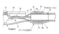
図7に示すように、信号ケーブル25としては多芯ケーブルが用いられる。この信号ケーブル25は、複数の素線65とこれらを束ねたシールド線(図示せず)とこれを覆う外皮66とから構成される。そして、複数の素線65とシールド線はメイン基板57及びサブ基板58に半田付けされる。なお、信号ケーブル25の各素線65はサブ基板58及びメイン基板57にそれぞれ接続する代わりに、どちらか一方に直接に接続されるものであってもよい。 As shown in FIG. 7, a multi-core cable is used as the
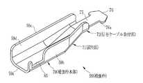
図8に示すように、補強枠59は、底板部59aとこの両端に連接される側板部59b,59cとにより、底板部59aの上方に開口部59dを有し横断面がU字形の樋状部材から構成される。この補強枠59は、プリズム53及びサブ基板58が収納される補強枠本体70と、これに続く絞り部71と、信号ケーブル取付部72とを有する。そして、一端側の補強枠本体70に前記プリズム保持部材54が、また他端側の信号ケーブル取付部72に前記信号ケーブル25の外皮25aがそれぞれ固着される。As shown in FIG. 8, the reinforcing frame 59 has abowl- like shapehaving an
補強枠本体70は、プリズム53及びサブ基板58が収納可能な横断面積となっており、信号ケーブル取付部72は信号ケーブル25の外皮25aが収納可能な横断面積となっている。このため、絞り部71は、信号ケーブル取付部72に向かうに従い、横断面積が次第に小さくなるように絞られている。また、この絞りによって、図6に示すように、撮影レンズ51の光軸CL1と、信号ケーブル25の中心軸CL2とがオフセットするようにX軸方向(水平線方向)のオフセット量OFx、Y軸方向(鉛直方向)のオフセット量OFyが設定されている。これらオフセット量OFx、OFyの分だけ、先端硬質部31の撮像装置取付孔45(図2参照)に対して信号ケーブル25をオフセットして配置することができる。 The reinforcing frame main body 70 has a transverse area that can accommodate the
このように、X軸方向のオフセット量OFx、Y軸方向のオフセット量OFyを補強枠59の絞り部71の形状を変えることにより適宜設定することができ、XY軸を含む面内で任意位置に信号ケーブル25を撮影光軸CL1に対してオフセットさせることができる。 As described above, the offset amount OFx in the X-axis direction and the offset amount OFy in the Y-axis direction can be appropriately set by changing the shape of the
図8に示すように、底板部59aの後端側には、底板部59aが後方に向かって延設され、接合片75が形成されている。この接合片75の後端両側縁には、係止爪76が両側方に延設されている。 As shown in FIG. 8, at the rear end side of the
図7に示すように、接合片75は、信号ケーブル25の外周下面に接触させた状態で結束糸78aが巻回され、接合片75及び信号ケーブル25を一体化させた糸巻78が構成される。なお、信号ケーブル25のシールド線が補強枠59に接触することがないように、糸巻78を形成する前に、素線65及びシールド線を覆うように、熱収縮の被覆チューブ77が外皮66に被せられる。そして、糸巻78は接着剤79により固着される。なお、被覆チューブ77と外皮66との間にも接着剤79が塗布されてこれらが一体化される。これら糸巻78及び接着剤79によりケーブル固定部61が構成される。このケーブル固定部61によって信号ケーブル25と補強枠59との結合強度が高められる。そして、糸巻78の後端に係止爪76の先端面76aが係止するため、湾曲部32による湾曲操作で信号ケーブル25が押し引きされ、この押し引きの力がこのケーブル固定部61に作用しても、係止爪76、糸巻78、接着剤79により結合強度が高められているので、補強枠59から信号ケーブル25がずれてしまうことがなく、素線65の半田付け部の剥がれや破損などの発生が抑えられる。 As shown in FIG. 7, the joining
また、接合片75を含む糸巻78及び接着剤79を覆うように、可撓性の保護チューブ80が被覆される。この保護チューブ80でケーブル固定部61が被覆されることにより、接合片75及び糸巻78・接着剤79で補強枠59に一体的に固定される信号ケーブル25が、湾曲部32の曲げ操作により曲げられる場合に、曲げ力を信号ケーブル25だけでなく保護チューブ80にも分散させることができ、その分だけ信号ケーブル25の曲げによる耐性を向上させることができる。 In addition, a flexible
図6に示すように、プリズム保持部材54を補強枠59に固定する際に、前記プリズム53の三面を前記底板部59a及び側板部59b,59cにより覆うようにして、前記プリズム53、前記サブ基板58が補強枠59に内蔵される。また、図4に示すように、一方の側板部59bにはプリズム保持部材54の側板部54aの一部が入り込む係止開口85が形成されている。この係止開口85は、プリズム保持部材54よりも後端側が大きく開口している。 As shown in FIG. 6, when the
CCD56を有するメイン基板57は、開口部59d(図8参照)を覆うように、補強枠59の外側に位置される。このように、CCD56を有するメイン基板57を補強枠59の外側に位置させることにより、被観察部位の変更に伴い受光部面積を変えず画素のサイズを小さくして高密度化すべく、CCD56のサイズを変更する場合でも、CCD56とそのメイン基板57及び必要に応じてサブ基板58を変更するだけでよく、解像度の仕様変更にも容易に対応が可能になる。しかも、その他の鏡筒52、プリズム53、プリズム保持部材54、補強枠59などの構成部材は変更する必要がなく、同一部品をそのまま使用することができ、部品点数の増加を抑えることができる。 The
図2に示すように、撮像装置26は、先端部本体35の撮像装置取付孔45に入れられて、固定ネジ86によって固定される。また、図9に示すように、二つの照明窓41,42に対応する位置には2本のライトガイド87,88がそれぞれ取り付けられる。また、送気・送水ノズル43には送気チューブ89及び送水チューブ90が連結される。 As shown in FIG. 2, the imaging device 26 is inserted into the imaging
図9は、図2におけるIX−IX線断面を示すもので、湾曲部32の中心軸に直交する横断面を示している。この横断面は、仮想線91によって90°間隔で4区画に分けている。仮想線91は、複数の節輪ユニット38の中心軸に対し点対称な位置で配置される1対の連結ピン39を繋いだものであり、これら仮想線91は隣接する連結ピン39の間では中心軸方向から見たときに90度の角度で交差している。そして、このうちの第1区間92aに前記鉗子チャンネル19を位置させる。また、第1区画92aに隣接する第2区画92bに第1ライトガイド87を位置させる。さらに、第3区画92cに前記信号ケーブル25及び第2ライトガイド88を位置させ、第4区画92dに前記送気チューブ89・送水チューブ90を位置させる。 FIG. 9 shows a cross section taken along line IX-IX in FIG. 2, and shows a cross section orthogonal to the central axis of the bending
鉗子チャンネル19の湾曲部32の湾曲操作によって鉗子チャンネル19に働く横方向の力(横力)は、アングル中心軸を通る対角方向に強くなる。アングル中心軸に対し、前記鉗子チャンネル19のほぼ対角位置に前記信号ケーブル25を位置決めすることにより、湾曲部32の湾曲操作による鉗子チャンネル19の湾曲挙動に対し、剛性バランスのとれる位置に、鉗子チャンネル19の次ぎに剛性が高い信号ケーブル25を位置させることができる。したがって、湾曲動作に対して、アングルの曲がり方のバランスがとれる。 The lateral force (lateral force) acting on the
また、鉗子チャンネル19の湾曲部32の湾曲操作によって鉗子チャンネル19に働く横力により、他のチューブ類を対角に移動させる力が働く。これに対し、補強枠59の絞り部71によるオフセット量を利用して、湾曲部32内の各区間92a〜92dの内、第1区画92aの鉗子チャンネル19に対し対角位置となる第3区画92cに信号ケーブル25を位置決めする。これにより、湾曲部32の湾曲による鉗子チャンネル19の変位に対して、その変位の影響による位置の変位が最も少ない対角位置に信号ケーブル25をセットすることができ、その分だけ、配列乱れを防止することができる。したがって、信号ケーブル25及びライトガイド88へのダメージが少なくなり、信号ケーブル自体の破断などの発生を抑えることができる。Moreover, the force which moves other tubes diagonally acts by the lateral force which acts on the
また、図3に示す第1照明窓41と送気・送水ノズル43との位置を入れ替えた図10に示すような第1照明窓41と送気・送水ノズル43の配置の場合にも、図11に示すように、補強枠59の絞り部71によるオフセット量を積極的に利用することにより、第1区間92aに鉗子チャンネル19を、この第1区画92aに隣接する第2区画92bに第1ライトガイド87、第3区画92cに信号ケーブル25及び送気チューブ89・送水チューブ90を、第4区画92dに第2ライトガイド88をそれぞれ位置させることができ、上記同様にして、鉗子チャンネル19の信号ケーブル25に対するストレスの軽減効果が得られ、同様にしてその分だけ耐久性が向上する。なお、オフセット量を用いた信号ケーブルの配置位置は、図9及び図11に示すものに限定されない。例えば、オフセット量を用いて湾曲部32の中心軸に対し、鉗子チャンネル19の対角位置に信号ケーブル25を位置決めする際に、信号ケーブル25を鉗子チャンネル19にさらに近接させてもよい。この場合には、鉗子チャンネル19及び信号ケーブル25を近接させることにより、軟性部33(図1参照)の細径化が図れる。 Also, in the case of the arrangement of the first illumination window 41 and the air /
以上のように、撮像装置26の補強枠59を用いて、湾曲部32内における信号ケーブル25と鉗子チャンネル19との位置決めを行い、しかも、他のライトガイド87,88などの内蔵物も、この補強枠59による緩い位置規制効果を受けるため、湾曲部32内のケーブル固定部61付近でピン39を乗り越えてチューブ類が各区画を移動する配列乱れの発生を抑えることができる。これにより、ピン39を乗り越えるときにピン39によりチューブ類が圧迫を受けることがなくなり、断線の発生が抑えられる。また、補強枠59による各チューブの緩い位置規制効果によって、各区画92a〜92d内で各チューブ類のクリアランスを確保したバランスの良い配置となり、バランス不良に起因する湾曲動作時の各チューブ類の摺動抵抗の増加も抑えられる。 As described above, the reinforcing frame 59 of the imaging device 26 is used to position the
本実施形態では、プリズム53の近傍でプリズム53の後端側であって、メイン基板57の下方の補強枠59内にサブ基板58を設けることと、素線65を短く加工すること、もしくは素線65を補強枠59内に折り畳み収納すること等により、ケーブル固定部61と基板57を近づけることで、図12(A)に示すように、その分だけ撮像装置26の長さ方向におけるL1分の短小化を図ることも可能になる。 In the present embodiment, the sub-board 58 is provided in the reinforcing frame 59 on the rear end side of the
これにより、先端筒37内で、第1節輪38aよりも先端側に、ケーブル固定部61を位置させることができる。したがって、図12(B)に示すような第1節輪38a以降の後端側にケーブル固定部61が位置する場合には、ケーブル固定部61の直後の部分が剛性変化点となり、応力集中して断線の懸念があるが、(A)のケーブル固定位置とすることで、湾曲部32が例えば最大限に湾曲した場合でも、ケーブル固定部61の近傍で信号ケーブル25が曲げられることが少なくなり、緩い曲線を描いて信号ケーブル25が湾曲すると共に、ケーブル固定部61に作用する折り曲げ力が小さくなる。これに応じて耐久性が向上する。 As a result, the
しかも、図12(B)のものは、剛性を有するケーブル固定部61が、湾曲が行われる第1節輪38a内に位置しているため、他のライトガイドなどとの干渉によるこれらの耐久性の低下などの懸念があったが、本実施形態では、柔軟性を有する信号ケーブル25自体が位置することになり、これらの懸念も解消する。このように、湾曲部32が同じ角度で湾曲する場合でも、ケーブル固定部61の位置を前後方向で変えることにより、ケーブル固定部61にかかる曲げ力の低減や、他のチューブ類に対する破損の懸念を無くすことができる。 Moreover, in FIG. 12B, since the rigid
なお、撮像装置26の短小化によるケーブル固定部61の先端筒37内における位置決めによる作用と、補強枠59によるオフセット作用との相乗効果で、湾曲部32内の内蔵物の耐久性をより一層向上させることができるが、上記補強枠59によるオフセット効果のみや、先端筒37内における信号ケーブル25の位置決め効果のみでも、湾曲部32内の内蔵物の耐久性を向上させることができるものであり、いずれか一方の構成であってもよい。 The durability of the built-in object in the
上記実施形態では、補強枠59内に接着剤を充填させて封止樹脂60としているが、充填に代えて、補強枠59内に接着剤を入れた状態でプリズム保持部材54やサブ基板58などを設置することで、補強枠59内に各内蔵物を封止してもよい。 In the embodiment described above, the reinforcing frame 59 is filled with an adhesive to form the sealing
また、上記実施形態では、メイン基板とこのメイン基板とは別体で構成されるサブ基板との組み合わせによる形態について説明したが、この他に、サブ基板は省略し、代わりに、撮像素子が取り付けられ、撮像素子とは異なる面に延出され屈曲される屈曲部を有する屈曲基板を用いた実施形態にも同様に本発明の適用が可能である。なお、屈曲基板は、フレキシブル基板であっても、あるいは可撓性の無い基板であってもよい。 Further, in the above-described embodiment, the form of the combination of the main board and the sub board formed separately from the main board has been described, but in addition to this, the sub board is omitted and an image sensor is attached instead. In addition, the present invention can be similarly applied to an embodiment using a bent substrate having a bent portion that extends and bends on a different surface from the imaging element. The bent substrate may be a flexible substrate or a non-flexible substrate.
上記実施形態では、プリズムを用いて光軸を曲げる方式の撮像素子横置き方式を採用しているが、プリズムを省略して撮像素子を縦置きにしたものに本発明を実施してもよい。また、信号ケーブルの素線を接着剤により一体化しているが、これは接着剤により固化しなくても良い。また、補強枠を樋状部材から構成したが、補強枠は、レンズ鏡筒の光軸と前記信号ケーブルの中心軸とをオフセットさせることができるものであればよく、筒状であったり、板状であったりしてもよい。さらに、補強枠の先端側固定の対象部材は、鏡筒の他に、先端部本体であってもよい。この場合には、先端部本体に補強枠の受け部を形成し、これに補強枠の先端部を嵌合させ、先端部本体に補強枠に固定することができる。In the above-described embodiment, the horizontal arrangement method of the image pickup device using the prism to bend the optical axis is adopted. However, the present invention may be implemented in a configuration in which the prism is omitted and the image pickup device is vertically installed. Although the wire of the signal cable are integratedwith an adhesive, which may not be solidifiedby an adhesive. Although constitute areinforcement frame from trough member,the reinforcing frame, as long as the optical axis of the lens barrel and the central axis of the signal cable as it cancause an offset, or a cylindrical shape, a plate It may be a shape. Further, the target member to be fixed to the distal end side of thereinforcing frame may be the distal end body in addition to the lens barrel. In this case, it is possible to form a receiving portion of thereinforcing frame to the distal end portion main body, which the leading edge of thereinforcing frame is fitted in and fixed to thereinforcing frame to the distal end body.
10 電子内視鏡システム
11 電子内視鏡
14 挿入部
25 信号ケーブル
26 撮像装置
31 先端硬質部
32 湾曲部
38 節輪ユニット
40 観察窓
41,42 照明窓
43 送気・送水ノズル
52 鏡筒
53 プリズム
54 プリズム保持部材
56 CCD
57 メイン基板
58 サブ基板
59 補強枠
59a 底板部
60 封止樹脂
61 ケーブル固定部
65 素線
66 外皮
70 補強枠本体
71 絞り部
72 信号ケーブル取付部
87,88 ライトガイド
89 送気チューブ
91 仮想線
92a,92b,92c,92d 区画DESCRIPTION OF SYMBOLS 10
57
Claims (8)
Translated fromJapanese前記レンズ鏡筒を介して結像される光学画像を光電変換する固体撮像素子と、
前記固体撮像素子が取り付けられる基板と、
複数の素線及びこれを覆う外皮からなり、前記素線が前記基板に電気的に接続されている信号ケーブルと、
底板部の両端に側板部が連接されて横断面がU字形であり、前記底板部の上方に開口部を有する樋状部材であって、一端が前記レンズ鏡筒に他端が前記信号ケーブルの外皮にそれぞれ固定されており、前記レンズ鏡筒の光軸と前記信号ケーブルの中心軸とをオフセットさせ、前記レンズ鏡筒と前記信号ケーブルとを段違いにする補強枠と
を備えることを特徴とする内視鏡用撮像装置。A lens barrel;
A solid-state imaging device that photoelectrically converts an optical image formed through the lens barrel;
A substrate to which the solid-state imaging device is attached;
A signal cable comprising a plurality of strands and a sheath covering the strands, wherein the strands are electrically connected to the substrate;
Side plate portions are connected to both ends of the bottom plate portion, and thecross section is U-shaped. A reinforcing frame that is fixed to the outer skin, offsets the optical axis of the lens barrel and the central axis of the signal cable, and makes the lens barrel and the signal cable uneven. An endoscope imaging device characterized by the above.
前記レンズ鏡筒を保持する保持部材と、
前記レンズ鏡筒を介して結像される光学画像を光電変換する固体撮像素子と、
前記固体撮像素子が取り付けられる基板と、
複数の素線及びこれを覆う外皮からなり、前記素線が前記基板に電気的に接続されている信号ケーブルと、
底板部の両端に側板部が連接されて横断面がU字形であり、前記底板部の上方に開口部を有する樋状部材であって、一端が前記保持部材に他端が前記信号ケーブルの外皮にそれぞれ固定されており、前記レンズ鏡筒の光軸と前記信号ケーブルの中心軸とをオフセットさせ、前記レンズ鏡筒と前記信号ケーブルとを段違いにする補強枠と、
を備えることを特徴とする内視鏡用撮像装置。A lens barrel;
A holding member for holding the lens barrel;
A solid-state imaging device that photoelectrically converts an optical image formed through the lens barrel;
A substrate to which the solid-state imaging device is attached;
A signal cable comprising a plurality of strands and a sheath covering the strands, wherein the strands are electrically connected to the substrate;
A side plate is connected to both ends of the bottom plate andhas a U-shaped cross section, and has an opening above the bottom plate. A reinforcement frame that offsets the optical axis of the lens barrel and the central axis of the signal cable, and makes the lens barrel and the signal cable in a step,
An endoscope imaging apparatus comprising:
前記基板は前記補強枠本体の前記開口を覆うことを特徴とする請求項1または2項記載の内視鏡用撮像装置。The reinforcing frame includes areinforcing frame main body, a throttle portion thatis continuous with the reinforcing frame main body and is narrowed so that a cross-sectional area of a cross section perpendicular to the heel direction gradually decreases toward the rear, and a rear end of the throttle portion A cable fixing portion into which the outer sheath of the signal cable is inserted, and the optical axis of the lens barrel and the central axis of the signal cable are offset by the diaphragm portion,
The endoscope imaging apparatus according toclaim 1, wherein the substrate covers the opening of the reinforcing frame body.
前記先端硬質部の先端面は、鉗子出口、観察窓、照明窓、送気・送水ノズルを有し、
前記先端硬質部内には、前記観察窓に対応する位置に前記内視鏡用撮像装置が取り付けられ、
前記照明窓に対応する位置にライトガイドが取り付けられ、
前記鉗子出口に鉗子チャンネルが取り付けられ、
前記送気・送水ノズルに、送気チューブ及び送水チューブが取り付けられ、
前記補強枠を用いて、前記挿入部の中心軸に対し、前記鉗子チャンネルの対角位置に前記信号ケーブルを位置決めすることを特徴とする内視鏡。An endoscope having a distal end hard portion to which the endoscope imaging device according to any one of claims 1 to 5 is attached,
The distal end surface of the distal rigid portion has a forceps outlet, an observation window, an illumination window, an air / water supply nozzle,
In the hard tip portion, the endoscope imaging device is attached at a position corresponding to the observation window,
A light guide is attached at a position corresponding to the lighting window,
A forceps channel is attached to the forceps outlet,
An air supply tube and a water supply tube are attached to the air supply / water supply nozzle,
An endoscope, wherein the signal cable is positioned at a diagonal position of the forceps channel with respect to a central axis of the insertion portion using thereinforcing frame .
前記湾曲部は、複数の節輪ユニットを連結ピンで連結し、前記連結ピンに操作ワイヤを通して上下左右に湾曲自在に構成され、
前記湾曲部の中心軸に直交する横断面における湾曲部内を、前記複数の節輪ユニットの中心軸に対し点対称な1対の連結ピンを繋ぐ仮想線によって90°間隔で4区画に分け、このうちの第1区間に前記鉗子チャンネルを位置させ、この第1区画に隣接する第2区画に第1ライトガイドを位置させ、第2区画に隣接する第3区画に前記信号ケーブル及び第2ライトガイドを位置させ、第3区画に隣接する第4区画に前記送気チューブ・送水チューブを位置させることを特徴とする請求項6記載の内視鏡。A curved portion following the hard tip portion,
The bending portion is configured to connect a plurality of node ring units with a connecting pin, and bendable vertically and horizontally through an operation wire to the connecting pin.
The inside of the curved portion in a cross section perpendicular to the central axis of the curved portion is divided into four sections at 90 ° intervals by virtual lines connecting a pair of connecting pins that are point-symmetric with respect to the central axis of the plurality of node units. The forceps channel is positioned in the first section, the first light guide is positioned in the second section adjacent to the first section, and the signal cable and the second light guide are positioned in the third section adjacent to the second section. The endoscope according to claim 6, wherein the air supply tube and the water supply tube are positioned in a fourth section adjacent to the third section.
前記湾曲部は、複数の節輪ユニットを連結ピンで連結し、前記連結ピンに操作ワイヤを通して上下左右に湾曲自在に構成され、
前記湾曲部の中心軸に直交する横断面における湾曲部内を、前記複数の節輪ユニットの中心軸に対し点対称な1対の連結ピンを繋ぐ仮想線によって90°間隔で4区画に分け、このうちの第1区間に前記鉗子チャンネルを位置させ、この第1区画に隣接する第2区画に第1ライトガイドを位置させ、第2区画に隣接する第3区画に前記信号ケーブル及び前記送気チューブ・送水チューブを位置させ、第3区画に隣接する第4区画に第2ライトガイドを位置させることを特徴とする請求項6記載の内視鏡。A curved portion following the hard tip portion,
The bending portion is configured to connect a plurality of node ring units with a connecting pin, and bendable vertically and horizontally through an operation wire to the connecting pin.
The inside of the curved portion in a cross section perpendicular to the central axis of the curved portion is divided into four sections at 90 ° intervals by virtual lines connecting a pair of connecting pins that are point-symmetric with respect to the central axis of the plurality of node units. The forceps channel ispositioned in the first section, the first light guide ispositioned in the second section adjacent to the first section, and the signal cable and the air supply tube arepositioned in the third sectionadjacent to thesecond section. The endoscope according to claim 6, wherein the water supply tube ispositioned, and the second light guide is positioned in the fourth sectionadjacent to the third section .
Priority Applications (3)
| Application Number | Priority Date | Filing Date | Title |
|---|---|---|---|
| JP2011074277AJP5250653B2 (en) | 2011-03-30 | 2011-03-30 | Endoscopic imaging apparatus and endoscope |
| CN201210046690.5ACN102727163B (en) | 2011-03-30 | 2012-02-27 | Endoscope and its camera device |
| CN201510559728.2ACN105223684B (en) | 2011-03-30 | 2012-02-27 | Endoscope apparatus |
Applications Claiming Priority (1)
| Application Number | Priority Date | Filing Date | Title |
|---|---|---|---|
| JP2011074277AJP5250653B2 (en) | 2011-03-30 | 2011-03-30 | Endoscopic imaging apparatus and endoscope |
Publications (2)
| Publication Number | Publication Date |
|---|---|
| JP2012205808A JP2012205808A (en) | 2012-10-25 |
| JP5250653B2true JP5250653B2 (en) | 2013-07-31 |
Family
ID=46984002
Family Applications (1)
| Application Number | Title | Priority Date | Filing Date |
|---|---|---|---|
| JP2011074277AActiveJP5250653B2 (en) | 2011-03-30 | 2011-03-30 | Endoscopic imaging apparatus and endoscope |
Country Status (2)
| Country | Link |
|---|---|
| JP (1) | JP5250653B2 (en) |
| CN (2) | CN105223684B (en) |
Families Citing this family (18)
| Publication number | Priority date | Publication date | Assignee | Title |
|---|---|---|---|---|
| JP5558399B2 (en)* | 2011-03-30 | 2014-07-23 | 富士フイルム株式会社 | Endoscopic imaging device |
| JP6307227B2 (en)* | 2013-06-28 | 2018-04-04 | オリンパス株式会社 | Imaging unit and endoscope apparatus |
| JP6349286B2 (en)* | 2015-01-26 | 2018-06-27 | 富士フイルム株式会社 | Optical device, electronic endoscope, and manufacturing method of optical device |
| CN107409172B (en)* | 2015-04-24 | 2020-05-19 | 日立汽车系统株式会社 | Image pickup apparatus |
| CN107072494A (en)* | 2015-06-16 | 2017-08-18 | 奥林巴斯株式会社 | Endoscope |
| JP6655343B2 (en)* | 2015-10-15 | 2020-02-26 | 富士フイルム株式会社 | Endoscope |
| WO2017217025A1 (en)* | 2016-06-17 | 2017-12-21 | オリンパス株式会社 | Endoscope device |
| JP6230771B1 (en)* | 2016-06-17 | 2017-11-15 | オリンパス株式会社 | Endoscope device |
| JP6650378B2 (en)* | 2016-09-08 | 2020-02-19 | 富士フイルム株式会社 | Endoscope |
| CN111065309B (en)* | 2017-09-01 | 2022-05-24 | 奥林巴斯株式会社 | Insertion part of endoscope |
| CN109717820B (en)* | 2018-12-07 | 2024-06-07 | 上海英诺伟医疗器械股份有限公司 | In-vivo detection device and system based on flexible tube |
| CN113365544B (en)* | 2019-02-15 | 2024-06-28 | 奥林巴斯株式会社 | Endoscope, grounding method, and grounding method of front end portion of endoscope |
| WO2020188723A1 (en)* | 2019-03-18 | 2020-09-24 | オリンパス株式会社 | Holding frame, endoscope distal end structure, and endoscope |
| WO2020188688A1 (en)* | 2019-03-18 | 2020-09-24 | オリンパス株式会社 | Tip end unit of endoscope |
| CN112657073A (en)* | 2019-10-16 | 2021-04-16 | 重庆海扶医疗科技股份有限公司 | Preparation method of ultrasonic tube and ultrasonic tube |
| CN111035350B (en)* | 2019-12-30 | 2022-06-07 | 常州延顺光电科技有限公司 | Preparation method of snake bone device of endoscope |
| DE102020134036A1 (en)* | 2020-12-17 | 2022-06-23 | Ambu A/S | Endoscope with an endoscope handle with a disconnect device |
| JP7555298B2 (en) | 2021-04-21 | 2024-09-24 | 富士フイルム株式会社 | Endoscope imaging device and endoscope |
Family Cites Families (31)
| Publication number | Priority date | Publication date | Assignee | Title |
|---|---|---|---|---|
| JPH0664243B2 (en)* | 1986-04-30 | 1994-08-22 | オリンパス光学工業株式会社 | Endoscope |
| JPS6321618A (en)* | 1986-07-15 | 1988-01-29 | Olympus Optical Co Ltd | Endoscope |
| JP2735101B2 (en)* | 1986-12-08 | 1998-04-02 | オリンパス光学工業株式会社 | Imaging device |
| JPS63119736A (en)* | 1987-10-08 | 1988-05-24 | オリンパス光学工業株式会社 | Endoscope |
| JP2610241B2 (en)* | 1990-11-29 | 1997-05-14 | 富士写真光機株式会社 | Wiring structure to solid-state image sensor in electronic endoscope |
| US5873816A (en)* | 1994-11-02 | 1999-02-23 | Olympus Optical Co., Ltd. | Electronic endoscope having an insertional portion a part of which is a conductive armor |
| JP3686110B2 (en)* | 1994-11-10 | 2005-08-24 | オリンパス株式会社 | Endoscope |
| JPH0990243A (en)* | 1995-09-22 | 1997-04-04 | Olympus Optical Co Ltd | Image pickup device |
| JP3905152B2 (en)* | 1996-07-05 | 2007-04-18 | オリンパス株式会社 | Imaging device for endoscope |
| JP4016459B2 (en)* | 1997-08-20 | 2007-12-05 | フジノン株式会社 | Stereoscopic endoscope |
| JP3742514B2 (en)* | 1998-10-16 | 2006-02-08 | オリンパス株式会社 | Imaging device |
| JP2000210252A (en)* | 1999-01-25 | 2000-08-02 | Sony Corp | Solid-state imaging device |
| JP2001212074A (en)* | 2000-02-07 | 2001-08-07 | Olympus Optical Co Ltd | Endoscope |
| JP3945133B2 (en)* | 2000-08-02 | 2007-07-18 | フジノン株式会社 | Endoscope observation window cleaning device |
| JP2003209751A (en)* | 2002-01-16 | 2003-07-25 | Olympus Optical Co Ltd | Solid-state imaging apparatus |
| JP2005204944A (en)* | 2004-01-22 | 2005-08-04 | Chinontec Kk | Endoscope |
| JP4377745B2 (en)* | 2004-05-14 | 2009-12-02 | オリンパス株式会社 | Electronic endoscope |
| JP5143332B2 (en)* | 2004-07-05 | 2013-02-13 | オリンパス株式会社 | Imaging device, fixing member for imaging device, and method of repairing imaging device |
| JP4484044B2 (en)* | 2004-07-29 | 2010-06-16 | 富士フイルム株式会社 | Ultrasound endoscope |
| JP4594703B2 (en)* | 2004-11-19 | 2010-12-08 | オリンパス株式会社 | Solid-state image sensor unit |
| JP4350652B2 (en)* | 2005-01-07 | 2009-10-21 | オリンパスメディカルシステムズ株式会社 | Endoscope insertion part and endoscope |
| JP2007097883A (en)* | 2005-10-05 | 2007-04-19 | Olympus Corp | Bending section structure for endoscope |
| JP2007286613A (en)* | 2006-03-22 | 2007-11-01 | Fujinon Corp | Endoscopic apparatus |
| JP2007301083A (en)* | 2006-05-10 | 2007-11-22 | Fujinon Corp | Endoscope |
| JP4682158B2 (en)* | 2007-01-16 | 2011-05-11 | オリンパスメディカルシステムズ株式会社 | Imaging device |
| JP5283343B2 (en)* | 2007-03-29 | 2013-09-04 | 富士フイルム株式会社 | Ultrasound endoscope |
| JP2009153902A (en)* | 2007-12-27 | 2009-07-16 | Fujinon Corp | Electronic endoscope |
| JP2010042120A (en)* | 2008-08-12 | 2010-02-25 | Fujifilm Corp | Endoscope |
| JP5279367B2 (en)* | 2008-07-01 | 2013-09-04 | 富士フイルム株式会社 | Endoscope |
| JP2010057749A (en)* | 2008-09-04 | 2010-03-18 | Fujifilm Corp | Wiring module, its manufacturing method, and endoscope |
| JP5558399B2 (en)* | 2011-03-30 | 2014-07-23 | 富士フイルム株式会社 | Endoscopic imaging device |
- 2011
- 2011-03-30JPJP2011074277Apatent/JP5250653B2/enactiveActive
- 2012
- 2012-02-27CNCN201510559728.2Apatent/CN105223684B/enactiveActive
- 2012-02-27CNCN201210046690.5Apatent/CN102727163B/enactiveActive
Also Published As
| Publication number | Publication date |
|---|---|
| CN105223684A (en) | 2016-01-06 |
| CN102727163A (en) | 2012-10-17 |
| CN102727163B (en) | 2015-09-16 |
| JP2012205808A (en) | 2012-10-25 |
| CN105223684B (en) | 2018-04-06 |
Similar Documents
| Publication | Publication Date | Title |
|---|---|---|
| JP5250653B2 (en) | Endoscopic imaging apparatus and endoscope | |
| JP5558399B2 (en) | Endoscopic imaging device | |
| CN104812290B (en) | Electronic endoscope | |
| JP5192559B2 (en) | Endoscope | |
| JP5308716B2 (en) | Electronic endoscope device | |
| JP4916595B2 (en) | Imaging unit | |
| US8674231B2 (en) | Endoscope | |
| JP2009153902A (en) | Electronic endoscope | |
| WO2013039059A1 (en) | Endoscope position detecting probe | |
| JP5901859B1 (en) | Endoscope bend tube, endoscope and method for manufacturing bend tube for endoscope | |
| JP3776755B2 (en) | Electronic endoscope | |
| JP2000232957A (en) | Endoscopic device | |
| JP2008253451A (en) | Distal end structure of endoscope | |
| JP5175639B2 (en) | Endoscope and its assembly method | |
| WO2018155066A1 (en) | Endoscope | |
| JPH1119035A (en) | Endoscope | |
| JP2001128937A (en) | Electronic endoscope | |
| JP2011200338A (en) | Electronic endoscope | |
| JP3290109B2 (en) | Endoscope | |
| JP2010005269A (en) | Medical scope and distal end portion connecting method in medical scope | |
| JP4127794B2 (en) | Endoscope | |
| JP4286086B2 (en) | Endoscope device | |
| JP2024103202A (en) | Vascular endoscopy | |
| JP4197796B2 (en) | Electronic endoscope | |
| JP2022110313A (en) | Endoscope |
Legal Events
| Date | Code | Title | Description |
|---|---|---|---|
| A977 | Report on retrieval | Free format text:JAPANESE INTERMEDIATE CODE: A971007 Effective date:20130131 | |
| A131 | Notification of reasons for refusal | Free format text:JAPANESE INTERMEDIATE CODE: A131 Effective date:20130206 | |
| A521 | Request for written amendment filed | Free format text:JAPANESE INTERMEDIATE CODE: A523 Effective date:20130222 | |
| TRDD | Decision of grant or rejection written | ||
| A01 | Written decision to grant a patent or to grant a registration (utility model) | Free format text:JAPANESE INTERMEDIATE CODE: A01 Effective date:20130319 | |
| A61 | First payment of annual fees (during grant procedure) | Free format text:JAPANESE INTERMEDIATE CODE: A61 Effective date:20130415 | |
| R150 | Certificate of patent or registration of utility model | Ref document number:5250653 Country of ref document:JP Free format text:JAPANESE INTERMEDIATE CODE: R150 | |
| FPAY | Renewal fee payment (event date is renewal date of database) | Free format text:PAYMENT UNTIL: 20160419 Year of fee payment:3 | |
| R250 | Receipt of annual fees | Free format text:JAPANESE INTERMEDIATE CODE: R250 | |
| R250 | Receipt of annual fees | Free format text:JAPANESE INTERMEDIATE CODE: R250 | |
| R250 | Receipt of annual fees | Free format text:JAPANESE INTERMEDIATE CODE: R250 | |
| R250 | Receipt of annual fees | Free format text:JAPANESE INTERMEDIATE CODE: R250 | |
| R250 | Receipt of annual fees | Free format text:JAPANESE INTERMEDIATE CODE: R250 | |
| R250 | Receipt of annual fees | Free format text:JAPANESE INTERMEDIATE CODE: R250 | |
| R250 | Receipt of annual fees | Free format text:JAPANESE INTERMEDIATE CODE: R250 | |
| R250 | Receipt of annual fees | Free format text:JAPANESE INTERMEDIATE CODE: R250 | |
| R250 | Receipt of annual fees | Free format text:JAPANESE INTERMEDIATE CODE: R250 | |
| R250 | Receipt of annual fees | Free format text:JAPANESE INTERMEDIATE CODE: R250 |