Movatterモバイル変換


[0]ホーム

URL:


JP5250451B2 - Floor cleaning machine - Google Patents

Floor cleaning machine
Download PDF

Info

Publication number
JP5250451B2
JP5250451B2JP2009045066AJP2009045066AJP5250451B2JP 5250451 B2JP5250451 B2JP 5250451B2JP 2009045066 AJP2009045066 AJP 2009045066AJP 2009045066 AJP2009045066 AJP 2009045066AJP 5250451 B2JP5250451 B2JP 5250451B2
Authority
JP
Japan
Prior art keywords
pad
cleaning
cleaning brush
floor
guard body
Prior art date
Legal status (The legal status is an assumption and is not a legal conclusion. Google has not performed a legal analysis and makes no representation as to the accuracy of the status listed.)
Active
Application number
JP2009045066A
Other languages
Japanese (ja)
Other versions
JP2010194204A (en
Inventor
哲也 佐藤
Current Assignee (The listed assignees may be inaccurate. Google has not performed a legal analysis and makes no representation or warranty as to the accuracy of the list.)
Amano Corp
Original Assignee
Amano Corp
Priority date (The priority date is an assumption and is not a legal conclusion. Google has not performed a legal analysis and makes no representation as to the accuracy of the date listed.)
Filing date
Publication date
Application filed by Amano CorpfiledCriticalAmano Corp
Priority to JP2009045066ApriorityCriticalpatent/JP5250451B2/en
Publication of JP2010194204ApublicationCriticalpatent/JP2010194204A/en
Application grantedgrantedCritical
Publication of JP5250451B2publicationCriticalpatent/JP5250451B2/en
Activelegal-statusCriticalCurrent
Anticipated expirationlegal-statusCritical

Links

Images

Landscapes

Description

Translated fromJapanese

本発明は、モータによって高速回転する洗浄ブラシ又は洗浄パッド(以下、単に洗浄ブラシ又はパッドと記す)によって床面を洗浄する床面洗浄機の技術分野に属するものであって、具体的には、洗浄時に洗浄ブラシ又はパッドの回転によって洗浄水が外部に飛散したり、或は、溢れ出ることを防止することができるスプラッシュガードを、高性能に実現する機能を備え、更に、洗浄終了時に洗浄ブラシ又はパッドを脱水回転する事によって、洗浄ブラシ又はパッドに含まれている洗浄で汚れた汚水の滴下を防止して、床面に洗浄水を残さないように工夫した床面洗浄機に関するものである。  The present invention belongs to the technical field of a floor surface cleaning machine that cleans a floor surface with a cleaning brush or cleaning pad (hereinafter simply referred to as a cleaning brush or pad) that rotates at high speed by a motor. It has a function to realize a high performance splash guard that can prevent washing water from splashing or overflowing by the rotation of the washing brush or pad at the time of washing. Or, it relates to a floor cleaning machine designed to prevent dripping of dirty water from cleaning contained in the cleaning brush or pad by rotating and dewatering the pad so as not to leave cleaning water on the floor. .

従来の一般的な床面洗浄機には、例えば特許文献1に示されているように、機体の後部に洗浄後の汚水を吸い取って汚水タンクに回収するスキージが連結されており、スキージは機体の走行に従って連結軸を支点にして左右横方向に回動しながら、床面上の汚水を吸い取る仕組に成っている。また、機体の底面に設けた洗浄ブラシ又はパッドをモータで回転して床面の洗浄を行う床面洗浄機では、洗浄時に洗浄ブラシ又はパッドをシリンダー等の昇降装置により床面に降下させて洗浄を行い、洗浄終了時には、洗浄ブラシ又はパッドの回転を停止した後、昇降装置によりこの洗浄ブラシ又はパッドを床面から上昇させている。  As shown inPatent Document 1, for example, a conventional general floor cleaning machine is connected to a squeegee that sucks sewage after washing and collects it in a sewage tank at the rear of the machine. In accordance with the traveling, the structure is configured to suck up the sewage on the floor surface while rotating in the horizontal direction with the connecting shaft as a fulcrum. In addition, in a floor cleaning machine that cleans the floor by rotating the cleaning brush or pad provided on the bottom of the machine with a motor, the cleaning brush or pad is lowered to the floor by a lifting device such as a cylinder during cleaning. At the end of cleaning, after the rotation of the cleaning brush or pad is stopped, the cleaning brush or pad is raised from the floor surface by the lifting device.

特開2001−112683号公報JP 2001-112683 A

ところが、従来の一般的な床面洗浄機では、洗浄終了直後、洗浄ブラシ又はパッドの周辺に汚水を含んだ洗浄水(以下単に洗浄汚水と記す)が滞留している為、洗浄ブラシ又はパッドは洗浄汚水を吸水してしまい、その結果、洗浄ブラシ又はパッドを床面から上昇させた際に、洗浄ブラシ又はパッドに吸水されていた洗浄汚水が床面上にポタポタと滴下して床面を汚してしまうため、何度もスキージにより洗浄汚水を吸い取らなければならず、非常に手間を費やし煩わしいといった問題があった。  However, in the conventional general floor cleaning machine, immediately after the cleaning is completed, cleaning water containing sewage (hereinafter simply referred to as cleaning sewage) stays around the cleaning brush or pad. As a result, when the cleaning brush or pad is lifted from the floor surface, the cleaning sewage water absorbed by the cleaning brush or pad drops dripping onto the floor surface and soils the floor surface. Therefore, the squeegee has to suck up the washed sewage many times, which is very troublesome and troublesome.

特に、洗浄ブラシ又はパッドが収められている洗浄室内の保水性が高い構造のスプラッシュガード(例えば後述のガード体)を採用した方式では、スプラッシュガード内に多量の洗浄汚水を保水していることより、洗浄終了後に洗浄ブラシ又はパッドがより多くの洗浄汚水を吸水してしまうため、この問題がより顕著となっていた。  In particular, in a method employing a splash guard (for example, a guard body described later) with a high water retention structure in the cleaning chamber in which the cleaning brush or pad is housed, a large amount of cleaning sewage is retained in the splash guard. Since the cleaning brush or pad absorbs more cleaning sewage after completion of cleaning, this problem has become more prominent.

更に、床面に滴下した洗浄汚水により足を滑らせて転倒し、怪我をする事故も多く発生しているため、上記洗浄汚水の処理対策を的確に、且つ、早急に行う必要があった。  In addition, there are many accidents in which a foot slips and falls due to the cleaning sewage dripped on the floor surface, and therefore it is necessary to take an appropriate and urgent measure for the treatment of the cleaning sewage.

よって本発明の技術的課題は、洗浄ブラシ又はパッドによる洗浄が済んだ後において、洗浄ブラシ又はパッドからの洗浄汚水の滴下を防止すると共に、洗浄後の床面を汚すことなく、更にスキージにより一度の吸い取り作業で床面に残った洗浄汚水を吸い取ることにより、手間をかけずに、尚且つ、スリップによる転倒事故を防止する事を可能にした床面洗浄機を提供することである。  Therefore, the technical problem of the present invention is that after the cleaning with the cleaning brush or the pad is completed, the cleaning brush or pad prevents the cleaning sewage from dripping, and the floor after the cleaning is not contaminated, and the squeegee once again. It is an object of the present invention to provide a floor washer that can prevent a fall accident due to slip without taking time and effort by sucking the cleaning sewage remaining on the floor surface during the sucking operation.

(1) 上記の技術的課題を解決するために、本発明の請求項1に係る床面洗浄機は、洗浄水を給水しながら、上面と外周面が覆われているガード体の内部で洗浄ブラシ又はパッドをモータで回転して床面を洗浄し、洗浄後の汚水をブロアーの吸引力によって上記洗浄ブラシ又はパッドの後方に配置したスキージで回収して汚水タンクに回収するか、又は、その汚水を浄化して洗浄水として再利用するように構成した床面洗浄機であって、上記モータによる洗浄ブラシ又はパッドの回転が停止される際に、上記のガード体を床面に接地させたまま、上記洗浄ブラシ又はパッドを床面より離間させて回転を行う脱水回転期間が設けられていることを特徴としている。(1) In order to solve the above technical problem, a floor cleaning machine according toclaim 1 of the present invention cleans inside a guard body whose upper surface and outer peripheral surface are covered while supplying cleaning water. The brush or pad is rotated by a motor to clean the floor surface, and the washed sewage is collected with a squeegee located behind the washing brush or pad by the suction force of the blower and collected in the sewage tank, or the A floor cleaning machine configured to purify sewage and reuse it as cleaning water, and when the rotation of the cleaning brush or pad by the motor is stopped, the guard body is grounded to the floor. A dehydration rotation period is provided in which the cleaning brush or pad is rotated away from the floor surface.

(2) また、本発明の請求項2に係る床面洗浄機は、前記洗浄ブラシ又はパッドの外周を囲むガード体が、内側エアガードの外周に間隔をあけて外側エアガードを並設し、且つ、上面を前記ガード体の天板で塞いだ内外二重式に構成され、これ等内外のエアガードの間に前記ブロアーの排気エアを導入せしめることを特徴としている。(2) Further, in the floor cleaning machine according toclaim 2 of the present invention, the guard body surrounding the outer periphery of the cleaning brush or pad has the outer air guard arranged in parallel with the outer periphery of the inner air guard, and The upper surface is covered with a top plate of the guard body so as to have an internal / external double type, and exhaust air of the blower is introduced between the internal and external air guards.

(3) また、本発明の請求項3に係る床面洗浄機は、前記ガード体が昇降機構によって床面より上昇を始めるタイミングが、前記洗浄ブラシ又はパッド用モータに対する通電停止時、若しくは、当該洗浄ブラシ又はパッドの回転停止時のいずれかであることを特徴としている。(3) Further, in the floor cleaning machine according toclaim 3 of the present invention, the timing at which the guard body starts to rise from the floor surface by the lifting mechanism is when the energization of the cleaning brush or the pad motor is stopped, or It is characterized in that it is either when the rotation of the cleaning brush or pad is stopped.

(4) また、本発明の請求項4に係る床面洗浄機は、上側部に前記モータを取り付け、下側部にはこのモータによって回転される前記洗浄ブラシ又はパッドを設けたモータ台を、前記ガード体の天板上に設けると共に、このモータ台と、前記昇降機構を構成するシリンダーによって上下回動される回動アームとの間には、上記シリンダーによる引き上げ動作に従って上記モータ台が引き上げられると、床面に接していた前記洗浄ブラシ又はパッドを前記途中位置まで引き上げて、前記モータによる洗浄ブラシ又はパッドの脱水回転を可能にする一方、上記シリンダーによる引き上げ動作が更に進むと、上記洗浄ブラシ又はパッドとガード体の双方を、連繋して前記上限位置まで引き上げることができる遅延連繋機構が設けられていることを特徴としている。(4) Further, in the floor cleaning machine according toclaim 4 of the present invention, the motor base is provided with the motor mounted on the upper side and the cleaning brush or pad rotated by the motor on the lower side. While being provided on the top plate of the guard body, the motor base is pulled up according to the lifting operation by the cylinder between the motor base and a rotating arm that is rotated up and down by the cylinder constituting the lifting mechanism. The cleaning brush or pad that has been in contact with the floor surface is pulled up to the middle position, and the dehydrating rotation of the cleaning brush or pad by the motor is enabled, and when the lifting operation by the cylinder further proceeds, the cleaning brush Or that there is provided a delay linkage mechanism that allows both the pad and the guard body to be linked and pulled up to the upper limit position. It is a symptom.

(5) また、本発明の請求項5に係る床面洗浄機は、前記ガード体の縦幅の長さ寸法が、前記洗浄ブラシ又はパッドを前記途中位置まで引き上げた際に、当該ガード体の下端が床面に対して接触状態を維持できる長さに構成されていることを特徴としている。(5) Further, in the floor cleaning machine according to claim 5 of the present invention, when the length of the vertical width of the guard body raises the cleaning brush or pad to the midway position, The lower end is configured to have a length that can maintain a contact state with the floor surface.

(6) また、本発明の請求項6に係る床面洗浄機は、前記遅延連繋機構が前記モータ台側又は回動アーム側のいずれか一方に縦設されたスリット状の長溝と、他方に設けられた上記長溝に移動自在に嵌め込まれる昇降軸とによって構成されていて、前記シリンダーによる引き上げ動作に従って、上記長溝の一端部に上記昇降軸が係止して上記モータ台が引き上げられると、床面に接していた前記洗浄ブラシ又はパッドを前記途中位置まで引き上げ、次いで、上記シリンダーによる引き上げ動作が更に進むと、上記洗浄ブラシ又はパッドとガード体の双方を、前記上限位置まで引き上げることができるように構成されていることを特徴としている。(6) Further, in the floor cleaning machine according toclaim 6 of the present invention, the delay linking mechanism has a slit-like long groove vertically provided on either the motor base side or the rotating arm side, and the other side. A lifting shaft that is movably fitted in the long groove provided, and the lifting shaft is locked to one end of the long groove and the motor base is pulled up according to the lifting operation by the cylinder. The cleaning brush or pad that has been in contact with the surface is pulled up to the intermediate position, and then when the lifting operation by the cylinder further proceeds, both the cleaning brush or pad and the guard body can be pulled up to the upper limit position. It is characterized by being configured.

(7) 更に、本発明の請求項7に係る床面洗浄機は、機体に搭載した吸引ブロアーの排気ホースを、その途中で機体の直進方向に対して左右横方向に二股に分岐し、これ等二股に分岐された各分岐ホースの両端を、前記ガード体を構成する天板の左右両側端に設けられ、且つ、各分岐ホースから送り込まれて来る排気を上記機体の走行方向に対して平行にガイドする排気口に接続して、吸引ブロアーからの排気をこれ等左右の排気口を通して、上記ガード体の内外二重に構成された内側排気エアガードと外側排気エアガードとの間の排気エア室内に及ぼすことを特徴としている。(7) Further, in the floor cleaning machine according to claim 7 of the present invention, the exhaust hose of the suction blower mounted on the fuselage is bifurcated into the left and right lateral directions with respect to the straight direction of the fuselage. Both ends of each bifurcated hose that is bifurcated are provided on the left and right sides of the top plate that constitutes the guard body, and the exhaust air fed from each branch hose is parallel to the traveling direction of the aircraft. The exhaust from the suction blower is passed through these left and right exhaust ports and into the exhaust air chamber between the inner exhaust air guard and the outer exhaust air guard, which are configured as the inner and outer doubles of the guard body. It is characterized by the effect.

上記(1)で述べた請求項1に係る手段によれば、洗浄後、床面より洗浄ブラシ又はパッドを上昇させた状態においても、洗浄ブラシ又はパッドは回転している事により、洗浄ブラシ又はパッドに含まれている洗浄汚水は遠心力により飛散し吹き飛ばされて、高い脱水効果が発揮されるため、洗浄終了後の走行時や待機時において、洗浄ブラシ又はパッドからの洗浄水の滴下がなくなり、床面を汚す事を防止できる。
更に、ガード体の保水効果により、洗浄ブラシ又はパッドの脱水時に発生する飛散した洗浄汚水を、ガード体の室内に留まらせることができ、加えて、洗浄ブラシ又はパッドは床面から上昇した状態で回転を停止し、次の洗浄作業までその状態を維持する為、床面上に残った洗浄ブラシ又はパッド周辺の洗浄汚水を吸水してしまう事が無い。
According to the means according toclaim 1 described in the above (1), even when the cleaning brush or the pad is lifted from the floor after the cleaning, the cleaning brush or the pad rotates so that the cleaning brush or the pad rotates. The cleaning sewage contained in the pad is scattered and blown away by centrifugal force, and a high dehydration effect is exerted. Therefore, there is no dripping of cleaning water from the cleaning brush or the pad when traveling or waiting after the cleaning is completed. , Can prevent the floor from getting dirty.
Furthermore, due to the water retention effect of the guard body, the scattered washing sewage generated when the washing brush or pad is dehydrated can remain in the guard body, and in addition, the washing brush or pad can be lifted from the floor surface. Since the rotation is stopped and the state is maintained until the next cleaning operation, the cleaning brush remaining on the floor or the cleaning sewage around the pad is not absorbed.

上記(2)で述べた請求項2に係る手段によれば、ガード体を床面より浮上する上昇方向に付勢させたことで、床面と内外排気エアガードの接触圧を低減しつつ、排気エア室内が大気圧以上となり、内側排気エアガードより内側の空間よりも気圧が高くなるために、内側排気エアガードがより確実に洗浄汚水をガード体の室内に留まらせながら床面の洗浄をおこなうことができる。また、洗浄汚水の飛散や湧出を確実に防止できるため、洗浄水の使用量を少なくでき、そのために洗浄水タンクや汚水タンクを小型化でき、床面洗浄機全体をコンパクトにする事が出来る。更に、洗浄ブラシ又はパッドの周辺には常に洗浄水を保水させることが出来るため、床面の洗浄効果が向上する。  According to the means according toclaim 2 described in the above (2), the guard body is urged in the ascending direction rising from the floor surface, thereby reducing the contact pressure between the floor surface and the inside / outside exhaust air guard. Since the air chamber is at atmospheric pressure or higher and the air pressure is higher than the space inside the inner exhaust air guard, the inner exhaust air guard can more reliably clean the floor surface while keeping the cleaning sewage in the guard body chamber. it can. In addition, since it is possible to reliably prevent washing sewage from splashing and flowing out, the amount of washing water used can be reduced, so that the washing water tank and the sewage tank can be miniaturized, and the entire floor washing machine can be made compact. Further, since the cleaning water can be always retained around the cleaning brush or pad, the cleaning effect of the floor surface is improved.

上記(3)で述べた請求項3に係る手段によれば、ガード体が床面から上昇するタイミングを、モータの通電が停止するか、もしくは洗浄ブラシ又はパッドの回転が停止するかに設定する事で、床面に残った洗浄汚水が、洗浄ブラシ又はパッドの回転による風であおられてガード体の外に漏れ出す事を防止する。また洗浄ブラシ又はパッドに含まれている洗浄汚水もガード体の外に飛び散らない。  According to the means according toclaim 3 described in the above (3), the timing when the guard body rises from the floor surface is set as to whether the energization of the motor is stopped or the rotation of the cleaning brush or the pad is stopped. In this way, the cleaning sewage remaining on the floor surface is prevented from leaking out of the guard body due to the wind generated by the rotation of the cleaning brush or pad. Also, the cleaning sewage contained in the cleaning brush or pad does not scatter out of the guard body.

上記(4)と(5)で述べた請求項4と5に係る手段によれば、ガード体が遅延連繋機構によってパッド又はブラシの上昇に対して遅動する為、洗浄ブラシ又はパッドの脱水回転時には、ガード体の下端が床面に接している事により、脱水処理により飛散した洗浄汚水がガード体の外に漏れ出す事を防止できる。  According to the means according toclaims 4 and 5 described in the above (4) and (5), since the guard body is delayed with respect to the rise of the pad or brush by the delay linkage mechanism, the dehydrating rotation of the cleaning brush or pad is performed. Sometimes, the lower end of the guard body is in contact with the floor surface, so that it is possible to prevent the cleaning sewage scattered by the dehydration process from leaking out of the guard body.

上記(6)で述べた請求項6に係る手段によれば、モータ台又は回動アームのいずれか一方に設けたスリット状の長溝に対して、他方に設けた昇降軸が係合していて、その長溝の長さにより洗浄ブラシ又はパッドとガード体の床面からの上昇動作の遅延時間が安定的に設定可能になる。  According to the means according toclaim 6 described in the above (6), the lifting shaft provided on the other side is engaged with the slit-like long groove provided on either the motor base or the rotating arm. Depending on the length of the long groove, it is possible to stably set the delay time of the lifting operation from the floor surface of the cleaning brush or pad and the guard body.

上記(7)で述べた請求項7に係る手段によれば、ガード体に流入する排気エアの経路を、機体の走行方向に対して平行にガイドする排気口がガード体上面両側端部に夫々設けられている事により、排気エア経路から床面に吹き付けられるエアの作用により、床面に残った洗浄汚水が走行方向に対して横方向に広がらない為、機体本体後部のスキージによる洗浄汚水を吸い取る作業も手間が掛からずスムーズに行える。  According to the means according toclaim 7 described in the above (7), the exhaust ports for guiding the path of the exhaust air flowing into the guard body in parallel to the traveling direction of the airframe are respectively provided at both end portions on the upper surface of the guard body. Since the cleaning sewage remaining on the floor does not spread laterally with respect to the traveling direction due to the action of air blown from the exhaust air path to the floor, the cleaning sewage by the squeegee at the rear of the machine body is removed. Absorbing work can be done smoothly without any hassle.

以上の如くであるから、上記(1)〜(7)で述べた手段によって、上述した技術的課題を解決して、前記従来技術の問題点を解消することができる。  As described above, the technical problems described above can be solved by the means described in the above (1) to (7), and the problems of the prior art can be solved.

以上述べた次第で、本発明に係る床面洗浄機によれば、以下の優れた効果を奏する事ができる。
(イ) 洗浄終了後の走行時や保管時において、洗浄ブラシ又はパッドからの洗浄汚水の滴下(ボタ漏れ)がなくなるため、床面に洗浄汚水を残すことなく、また、何度もスキージによる吸引作業を行わなくてすみ、作業者の負担の軽減を図ることができる。
(ロ) また、床面への洗浄汚水残しによるスリップ転倒事故も防止する事が可能となり、より安全な清掃作業を行う事ができる。
(ハ) 更に、洗浄ブラシ又はパッドの脱水運転時には、ガード体が床面上に接地していることにより、決して洗浄汚水がガード体の外に漏れ出したり、飛散したりする事がないため、床面をきれいな状態に洗浄することができる。
(ニ) 加えて、スキージに吸引作用を及ぼす吸引ブロアーの排気エアーを利用したエアガードを使用することによって、床面との接触による傷つきや摩耗の問題と、塵埃の飛散の問題も解消しつつ、優れた洗浄水の飛散防止機能と溢出防止機能を発揮できる。
As described above, according to the floor cleaning machine of the present invention, the following excellent effects can be obtained.
(B) When running and storing after cleaning, there is no dripping (bottom leakage) of cleaning sewage from the cleaning brush or pad, so suction without squeegee remains on the floor and repeated suction. There is no need to perform work, and the burden on the operator can be reduced.
(B) In addition, it is possible to prevent a slip overturn accident due to a waste of cleaning sewage on the floor surface, so that safer cleaning work can be performed.
(C) In addition, since the guard body is grounded on the floor surface during the dehydration operation of the cleaning brush or pad, the cleaning sewage never leaks out or splashes out of the guard body. It is possible to clean the floor surface.
(D) In addition, by using an air guard that uses the exhaust air of the suction blower that exerts a suction action on the squeegee, the problem of scratches and wear due to contact with the floor surface and the problem of dust scattering are eliminated. Excellent cleaning water splash prevention function and overflow prevention function.

本発明に係る床面洗浄機の外観および内部の給排水経路の構造を説明した構成図。The block diagram explaining the structure of the external appearance of the floor surface washing machine which concerns on this invention, and an internal water supply / drainage path | route.本発明に係る床面洗浄機で用いる洗浄ブラシ又はパッド用昇降機構の実施例を示した側面図。The side view which showed the Example of the raising / lowering mechanism for cleaning brushes or pads used with the floor cleaning machine which concerns on this invention.本発明に係る床面洗浄機で用いる昇降機構の実施例を示した斜視図。The perspective view which showed the Example of the raising / lowering mechanism used with the floor cleaning machine which concerns on this invention.本発明に係る床面洗浄機で用いる洗浄ブラシ又はパッドの実施例を示した要部断面図。The principal part sectional drawing which showed the Example of the cleaning brush or pad used with the floor surface washing machine which concerns on this invention.本発明に係る床面洗浄機で用いる洗浄ブラシ又はパッドの実施例を示した要部詳細断面図。The principal part detailed sectional drawing which showed the Example of the cleaning brush or pad used with the floor surface washing machine which concerns on this invention.本発明に係る床面洗浄機で用いる洗浄ブラシ又はパッドの他の実施例の要部詳細断面図。The principal part detailed sectional drawing of the other Example of the washing brush or pad used with the floor surface washing machine which concerns on this invention.本発明に係る床面洗浄機で用いるガード体の要部詳細図であって、(1)は底面図、(2)は側面図、(3)は底面側から見た斜視図。It is principal part detail drawing of the guard body used with the floor cleaning machine which concerns on this invention, Comprising: (1) is a bottom view, (2) is a side view, (3) is the perspective view seen from the bottom face side.本発明に係る床面洗浄機の動作状態を説明した要部の側面図であって、(1)は洗浄前の状態、(2)は洗浄時の状態、(3)は脱水時の状態を示す。It is a side view of the principal part explaining the operation state of the floor cleaning machine concerning the present invention, (1) is the state before washing, (2) is the state at the time of washing, (3) is the state at the time of dehydration. Show.本発明に係る床面洗浄機の動作を説明したタイムチャート。The time chart explaining operation | movement of the floor cleaning machine which concerns on this invention.本発明に係る床面洗浄機の実施例の制御部を説明したブロック図。The block diagram explaining the control part of the Example of the floor cleaning machine which concerns on this invention.

以下に、上述した本発明に係る床面洗浄機の実施形態を添付した図面と共に詳細に説明するが、これらの実施形態は本発明の好適な具体例であり、技術的に好ましい種々の限定を付している場合もあるが、本発明の技術範囲は、特に本発明を限定する記載がない限りこれらの態様に限定されるものではない。  Hereinafter, embodiments of the floor cleaning machine according to the present invention described above will be described in detail with reference to the accompanying drawings. These embodiments are preferable specific examples of the present invention, and various technically preferable limitations are described below. The technical scope of the present invention is not limited to these embodiments unless specifically described to limit the present invention.

而して、本発明に係る床面洗浄機の実施の形態を図面と共に説明すると、図1は本発明の床面洗浄機の一例を示した構成図であって、図中、符号1で全体的に示したのは床面洗浄機の機体、2と3は走行用の車輪、2Mはこの車輪2を駆動回転する走行用モータ、4は取付ブラケット4Aによって機体1の後部上側に取付けた操作ハンドル、5はこの操作ハンドル4に取付けた操作ボックス、5Aはハンドル軸、5Bはスキージ6を上下動する操作レバーを示す。  Thus, an embodiment of the floor cleaning machine according to the present invention will be described with reference to the drawings. FIG. 1 is a block diagram showing an example of the floor cleaning machine of the present invention. Specifically, the floor cleaning machine body, 2 and 3 are traveling wheels, 2M is a traveling motor for driving and rotating thewheel 2, and 4 is an operation mounted on the rear upper side of thebody 1 by a mountingbracket 4A. Ahandle 5 is an operation box attached to theoperation handle 4, 5A is a handle shaft, and 5B is an operation lever for moving thesqueegee 6 up and down.

更に図中、Vは機体1内に搭載した電源用のバッテリー、7と7Mは同じく機体1内に取付けた汚水吸引用ブロアーとブロアー用モータであって、上述したスキージ6は、ホース6Hを通して送られて来る上記ブロアー7の吸引作用によって、床面FL上の汚水を吸い取って汚水タンク1Wに回収する仕組みに成っている。6Tはこのスキージ6を機体1の後部に取付けたアーム、6Sは上記操作レバー5Bの回動操作によってスキージ6を上下動する紐体、8は機体1の前面側底面部分に取付けた洗浄ブラシ又はパッド、8Hは洗浄ブラシ又はパッド8を一体的に取付けた回転盤、8Mと8Dは洗浄用モータとその回転軸、符号20で全体的に示したのは洗浄ブラシ又はパッド8の外周を囲むように形成したガード体であって、洗浄ブラシ又はパッド8はモータ8Mで回転しながら洗浄水タンク(図示省略)から送られて来る洗浄水CWを図4に示した給水口9より給水しながら床面FLを洗浄し、洗浄後の汚水をスキージ6が吸引して汚水タンク1Wに回収するように構成されている。  Further, in the figure, V is a battery for power supply mounted in thebody 1, 7 and 7M are a sewage suction blower and a blower motor mounted in thebody 1, and thesqueegee 6 described above is sent through ahose 6H. By the suction action of theblower 7, the sewage on the floor surface FL is sucked and collected in thesewage tank 1W. 6T is an arm that attaches thesqueegee 6 to the rear part of themachine body 1, 6S is a string body that moves thesqueegee 6 up and down by rotating theoperation lever 5B, and 8 is a cleaning brush that is attached to the bottom part on the front side of themachine body 1. Pads, 8H is a rotating disk on which the cleaning brush orpad 8 is integrally mounted, 8M and 8D are cleaning motors and their rotating shafts, and areference numeral 20 generally indicates the outer periphery of the cleaning brush orpad 8. The cleaning brush orpad 8 is rotated by amotor 8M while the cleaning water CW fed from a cleaning water tank (not shown) is supplied from thewater supply port 9 shown in FIG. The surface FL is cleaned, and thesqueegee 6 sucks the cleaned sewage and collects it in thesewage tank 1W.

次ぎに、上記の洗浄ブラシ又はパッド8とガード体20を昇降作動するための昇降機構(昇降装置)の構成例を、図2及び図3の記載と共に説明すると、図中、1Rは機体1の機体フレーム、30はこの機体フレーム1Rに取り付けた略ボックス状のホルダーで、このホルダー30の内部にはシリンダー31が取り付けられ、このシリンダー31の作動によって上下に出没作動するシリンダーロッド31Aの上端部には、連結軸32Aを用いてジョイントアーム32の一端部が連結されている。  Next, a configuration example of an elevating mechanism (elevating device) for elevating and lowering the cleaning brush orpad 8 and theguard body 20 will be described with reference to FIGS. 2 and 3. In FIG. Thebody frame 30 is a substantially box-shaped holder attached to thebody frame 1R. Acylinder 31 is attached to the inside of theholder 30, and thecylinder rod 31A that moves up and down by the operation of thecylinder 31 is attached to the upper end of thecylinder rod 31A. Are connected to one end of thejoint arm 32 using a connectingshaft 32A.

更に図1、図2、図3において、33は後述する回動アーム38に設けたビーム40に下端部を取り付けることによって、上記ホルダー30に並んだ状態に立設されるリフトフレーム、34はこのリフトフレーム33の内部に設けたスライドシャフトで、このスライドシャフト34の上端部に取付軸34Aを用いて上記ジョイントアーム32の他端部が連結され、更に、上記リフトフレーム33の内部に設けたバネ受け33Aと上記ジョイントアーム32の間に圧縮バネ35を介在することによって、昇降機構が構成される。この昇降機構によれば、図示の状態からシリンダーロッド31Aを下方へ引き込み作動されると、スライドシャフト34が圧縮バネ35を圧縮しながらシリンダーロッド31Aと一緒に下方へ降下作動される仕組みに成っている。  1, 2, and 3,reference numeral 33 denotes alift frame 34 that is erected in a state of being aligned with theholder 30 by attaching a lower end portion to abeam 40 provided on arotating arm 38 described later. A slide shaft provided inside thelift frame 33, the other end of thejoint arm 32 is connected to the upper end of theslide shaft 34 using anattachment shaft 34 </ b> A, and a spring provided inside thelift frame 33. An elevating mechanism is configured by interposing acompression spring 35 between thereceiver 33A and thejoint arm 32. According to this lifting mechanism, when thecylinder rod 31A is pulled downward from the illustrated state and operated, theslide shaft 34 is moved downward together with thecylinder rod 31A while compressing thecompression spring 35. Yes.

次ぎに、36と37は上記機体フレーム1Rの両側に間隔をあけて設けたアームステー、38はこれ等両アームステー36,37の間に架設した取付軸39に根端部を取り付けた回動アーム、40は上記回動アーム38の中間部に固定軸41を用いて取り付けたビームで、このビーム40に上述したリフトフレーム33の下端部が取り付けられている。  Next, 36 and 37 are arm stays provided at intervals on both sides of thebody frame 1R, and 38 is a rotation with a root end portion attached to a mountingshaft 39 installed between these arm stays 36 and 37. Anarm 40 is a beam attached to an intermediate portion of therotating arm 38 using a fixedshaft 41, and the lower end portion of the above-describedlift frame 33 is attached to thebeam 40.

また、11は下向きに略直角に曲げて形成した前記回動アーム38の先端部38Aを、上記モータ台10に固定した支持板12側に連結する昇降軸としてのモータ台固定ボルト、13は前記ガード体20を構成する天板21の上面に固定された支持部材で、この支持部材13の先端面には、上記モータ台固定ボルト11を移動自在に嵌め込んだスリット状の長溝13Kが、上向き垂直方向に設けられている。  Reference numeral 11 denotes a motor base fixing bolt as a lifting shaft for connecting atip end portion 38A of therotating arm 38 formed by bending downward at a substantially right angle to thesupport plate 12 side fixed to themotor base 10, and A support member fixed to the upper surface of thetop plate 21 constituting theguard body 20, and a slit-likelong groove 13 </ b> K in which the motorbase fixing bolt 11 is movably fitted on the front end surface of thesupport member 13 faces upward. It is provided in the vertical direction.

更に図中、14は前記吸引用ブロアー7の排気ホース体、14Lと14Rはこの排気ホース体14に分岐接続した左右の排気ホースであって、これ等左右の排気ホース14L,14Rの下端部は、上記ガード体20の天板21上に設けた左右の排気ボックス15L,15Rに接続されている。  Further, in the figure, 14 is an exhaust hose body of thesuction blower 7, 14L and 14R are left and right exhaust hoses branched and connected to theexhaust hose body 14, and the lower ends of these left andright exhaust hoses 14L and 14R are The left andright exhaust boxes 15L, 15R provided on thetop plate 21 of theguard body 20 are connected.

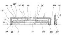
次ぎに、上述したガード体20の構成を図4乃至図7の記載に基づいて説明すると、図4は要部断面図、図5は要部詳細断面図、図6は他の実施例の要部詳細断面図、図7はその要部詳細図を示す。なお、これら図面に示した実施形態は本発明の好適な具体例であり、技術的に好ましい種々の限定を付している場合もあるが、本発明の技術範囲は、特に本発明を限定する記載がない限りこれらの態様に限定されるものではない。  Next, the configuration of theguard body 20 described above will be described with reference to FIGS. 4 to 7. FIG. 4 is a cross-sectional view of the main part, FIG. 5 is a detailed cross-sectional view of the main part, and FIG. Part sectional drawing, FIG. 7 shows the principal part detailed drawing. The embodiments shown in these drawings are preferred specific examples of the present invention, and may have various technically preferable limitations. However, the technical scope of the present invention particularly limits the present invention. Unless otherwise stated, the present invention is not limited to these embodiments.

上記の各図において、夫々符号20で全体的に示した上記のガード体は、前述した洗浄ブラシ又はパッド8の周囲に設けた空間部に配置されるものであって、ガード体20の全体は、洗浄ブラシ又はパッド8の上面を覆う円板形状の天板21と、この天板21の底面の外周部に、上記の洗浄ブラシ又はパッド8の周囲を囲むように内外二重に、而も、間隔をあけて下向きに並設した内側排気エアガード22、及び、外側排気エアガード23によって底面開口形状に構成されていて、内側排気エアガード22の内部空間が、上記洗浄ブラシ又はパッド8が回転する洗浄室20Aに成っている。尚、図面において21Hは天板21の中央に設けた穴、8Tはモータフランジである。  In each of the above drawings, the guard body generally indicated byreference numeral 20 is disposed in a space provided around the cleaning brush orpad 8 described above, and theentire guard body 20 is The disc-shapedtop plate 21 that covers the upper surface of the cleaning brush orpad 8 and the outer peripheral portion of the bottom surface of thetop plate 21 are doubled inside and outside to surround the cleaning brush orpad 8. The innerexhaust air guard 22 and the outerexhaust air guard 23 that are arranged in parallel downwardly at an interval are configured to have a bottom opening shape, and the inner space of the innerexhaust air guard 22 is cleaned by the cleaning brush orpad 8 rotating. It consists ofchamber 20A. In the drawings, 21H is a hole provided in the center of thetop plate 21, and 8T is a motor flange.

また、両側を上記内外の排気エアガード22,23にて仕切られ、上面を天板21で塞がれた底面開口形状の空間が排気エア室20Hに成っていて、断面が底面開口型の略円環形状を成すこの排気エア室20Hの左右上面に、上記左右の排気ホース14L,14Rの各下端口を接続した前記左右の排気ボックス15L,15Rの排気口15Zが連通接続されていて、これ等両ホース14L,14Rを通して送られて来る前記ブロアー7からの排気によって、当該排気エア室20H内の圧力を増加して、この増加した圧力によって上記ガード体20の全体が床面FLより浮上する上昇方向へ付勢されている。  Further, a space having a bottom opening shape in which both sides are partitioned by the inside and outside exhaust air guards 22 and 23 and the top surface is closed by thetop plate 21 is formed in theexhaust air chamber 20H, and the cross section is a substantially circular shape having a bottom opening type.Exhaust ports 15Z of the left andright exhaust boxes 15L, 15R connected to the lower end ports of the left andright exhaust hoses 14L, 14R are connected to the left and right upper surfaces of theexhaust air chamber 20H having an annular shape. The exhaust from theblower 7 sent through both thehoses 14L and 14R increases the pressure in theexhaust air chamber 20H, and the increased pressure causes theentire guard body 20 to rise above the floor surface FL. It is biased in the direction.

更に上記のガード体20を構成する内外の排気エアガード22,23は、図5の断面図に示す如く内側排気エアガード22の上下丈の長さを、その下端部側が床面FLに対して当接しやすいように、上記外側排気エアガード23の上下丈の長さよりも長く構成すると共に、この外側排気エアガード23の上下丈の長さを、その下端部と床面FLとの間に隙間FXが生じるように短く構成している。  Further, as shown in the sectional view of FIG. 5, the inner and outer exhaust air guards 22 and 23 constituting theguard body 20 have the vertical length of the innerexhaust air guard 22 and the lower end portion abuts against the floor surface FL. For ease of explanation, the outerexhaust air guard 23 is configured to be longer than the vertical length, and the vertical length of the outerexhaust air guard 23 is set so that a gap FX is formed between the lower end portion and the floor surface FL. It is composed shortly.

また、図4において符号20Xで示したのは、洗浄室20Aと外部とを連通するバイパス通路である。このバイパス通路20Xは予め設定した高さに設けられていて、この高さ以上に保水された洗浄水CWはオーバーフローとして常にスキージ6側に排出させるようにし、必要な保水量を自動的に維持できるように工夫している。また、このバイパス通路20Xは実施例ではスキージ6の方向に1箇所のみ設けたが、複数のバイパス通路20X…をスキージ6方向の後ろ側に向けて設けてもよい。更に図4において、9は給水タンク(図示省略)より送られて来る洗浄水CWを矢印に示す如く洗浄室20A内の洗浄ブラシ又はパッド8付近に給水する給水ホースであって、給水された洗浄水CWは、前記回転盤8Hの中心部付近に設けた通路8Xを通って中心部に給水される仕組みに成っている。  Also, what is indicated byreference numeral 20X in FIG. 4 is a bypass passage that communicates thecleaning chamber 20A with the outside. Thebypass passage 20X is provided at a preset height, and the wash water CW retained above this height is always discharged to thesqueegee 6 side as an overflow, so that the necessary water retention amount can be automatically maintained. It is devised as follows. Further, in the embodiment, only onebypass passage 20X is provided in the direction of thesqueegee 6, but a plurality ofbypass passages 20X may be provided toward the rear side in the direction of thesqueegee 6. Further, in FIG. 4, 9 is a water supply hose for supplying cleaning water CW sent from a water supply tank (not shown) to the vicinity of the cleaning brush orpad 8 in thecleaning chamber 20A as shown by the arrow, and the supplied cleaning hose. The water CW is configured to be supplied to the central portion through apassage 8X provided near the central portion of therotating disk 8H.

図6は本発明に係る床面洗浄機の他の実施例の要部詳細断面図を示したものであって、この実施例では前述したガード体20を一体ではなく、床面FLに接する部分を可撓性の材質の部材で構成し、前記ガード体20の一部若しくは全部を可撓性部材より構成して、少なくとも外側排気エアガード23を内側排気エアガード22よりも撓みやすい形状で構成している。  FIG. 6 shows a detailed cross-sectional view of an essential part of another embodiment of the floor cleaning machine according to the present invention. In this embodiment, the above-mentionedguard body 20 is not integrated but is in contact with the floor surface FL. Is formed of a member made of a flexible material, a part or all of theguard body 20 is formed of a flexible member, and at least the outerexhaust air guard 23 is configured to be more easily bent than the innerexhaust air guard 22. Yes.

すなわち、上記ガード体20の底面部に取り付けられる可撓性ガード体20’を構成する可撓性外側排気エアガード部23Hは、図6の矢印Xで示した撓み方向に撓み易い形状で構成されているため、前述の様にブロアー7の吸引力を可変させた場合などに排気エア量が必要以上に増えた場合に、この外側排気エアガード部23Hが外側に撓んで、内側排気エアガード部22Hとの空間部20Zが開放され、排気エア室20H内の排気エアを連通口20Sを通して外部へ逃がすように作用をすることで、図5に示した前述の段差(隙間FX)を設けたガード体20と同様な効果が発揮できる。  That is, the flexible outer exhaustair guard portion 23H constituting theflexible guard body 20 ′ attached to the bottom surface portion of theguard body 20 is configured to be easily bent in the bending direction indicated by the arrow X in FIG. Therefore, when the amount of exhaust air increases more than necessary when the suction force of theblower 7 is varied as described above, the outer exhaustair guard portion 23H bends outward, and the inner exhaustair guard portion 22H The space 20Z is opened, and theguard body 20 provided with the above-described step (gap FX) shown in FIG. 5 is provided by acting so that the exhaust air in theexhaust air chamber 20H is released to the outside through thecommunication port 20S. Similar effects can be achieved.

図7は全体を略ドーナツ形状に形成した上記可撓性ガード体20’の詳細を示したものであって、(1)は平面図、(2)は側面図、(3)は裏側より見た斜視図であり、実施に当たってはさらに内側排気エアガード部22Hにクッションチューブ部22Tを設けて、床面FLへの追従性も向上させる手段を講じることも有効な手段である。また、このような可撓性外側排気エアガード部23Hを実現するに当たっては、図6で示した可撓性外側排気エアガード部23Hの断面形状を有する一体の直線部材を、円形に撓ませて両端を接着して製作するのが常套手段であり、さらに排気エア室20Hと空間部20Zを連通させるために、連通口20Sを図の様に複数設けて製作するのが良い。この場合、可撓性外側排気エアガード部23Hや内側排気エアガード部22Hの断面形状を有する一体の直線部材を成型して製作した後、これを所定長さに切断し、プレス工程により連通口20Sを開口させ、前後端を接着して円形にすることで容易に製作が可能である。  FIG. 7 shows the details of the flexible guard body 20 'formed in a substantially donut shape as a whole. (1) is a plan view, (2) is a side view, and (3) is viewed from the back side. In practice, it is also effective to provide acushion tube portion 22T on the inner exhaustair guard portion 22H to improve the followability to the floor surface FL. Further, in order to realize such a flexible outer exhaustair guard part 23H, the integral linear member having the cross-sectional shape of the flexible outer exhaustair guard part 23H shown in FIG. It is a conventional means to manufacture by bonding, and it is preferable to manufacture by providing a plurality ofcommunication ports 20S as shown in the figure in order to connect theexhaust air chamber 20H and the space 20Z. In this case, an integrated linear member having a cross-sectional shape of the flexible outer exhaustair guard portion 23H and the inner exhaustair guard portion 22H is molded and manufactured, and then cut into a predetermined length, and thecommunication port 20S is formed by a pressing process. It can be easily manufactured by opening and bonding the front and rear ends into a circular shape.

この様にして構成した床面洗浄機においては、通常の床面洗浄作業中に洗浄室20Aに供給する洗浄水CWの供給量を極力少なくしても、洗浄室20Aから外部に洗浄水CWが湧出しにくいために洗浄力が維持でき、さらにその場に洗浄水CWが留まる時間が長いために洗浄力が向上する。  In the floor cleaning machine configured in this way, even if the supply amount of the cleaning water CW supplied to thecleaning chamber 20A is reduced as much as possible during the normal floor cleaning operation, the cleaning water CW is discharged from thecleaning chamber 20A to the outside. The cleaning power can be maintained because it is difficult to spring out, and the cleaning power is improved because the cleaning water CW stays there for a long time.

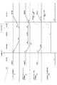
次ぎに、以上の如く構成した本発明に係る床面洗浄機の動作を図8の動作説明図及び図9のタイムチャートと共に説明する。  Next, the operation of the floor cleaning machine according to the present invention configured as described above will be described with reference to the operation explanatory diagram of FIG. 8 and the time chart of FIG.

図8(1)は洗浄前の状態を示す。
洗浄ブラシ又はパッド8は床面FLから引き上げられた洗浄前の状態を示したものであって、この状態では洗浄ブラシ又はパッド8の回転は停止している。ガード体20も、天板に取り付けられている支持板12のスリット溝13K内に係合している回動アーム38の昇降軸としてのモータ台固定ボルト11により、床面FLから吊り上げられている。尚、側面から見ると洗浄ブラシ又はパッド8の底面は、ガード体20の底面より10mm程度上部に位置している。
FIG. 8 (1) shows a state before cleaning.
The cleaning brush orpad 8 shows a state before cleaning that is lifted from the floor surface FL, and in this state, the rotation of the cleaning brush orpad 8 is stopped. Theguard body 20 is also lifted from the floor surface FL by a motorbase fixing bolt 11 as an elevating shaft of therotating arm 38 engaged in theslit groove 13K of thesupport plate 12 attached to the top plate. . When viewed from the side, the bottom surface of the cleaning brush orpad 8 is located about 10 mm above the bottom surface of theguard body 20.

図8(2)は洗浄時の状態を示す。
図10に示した入力装置62内の洗浄開始釦を押すと、洗浄ブラシ又はパッド8が回転を始め、シリンダー31の降下作動により回動アーム38のモータ固定ボルト11も引き下げられ、ガード体20が自重で降下して床面FLに接した後、洗浄ブラシ又はパッド8も接地する。更に洗浄ブラシ又はパッド8のみ降下し、床面FLに対して図示しない洗浄ブラシ又はパッド押圧力調整機構により、洗浄ブラシ又はパッド8に対して床面FLへの一定の押圧力が付与されて、優れたブラッシング効果を発揮すると共に、床面FLからの応力に対してもそれを押さえる押圧作用とサスペンション作用を同時に発揮するため、床面FLの多少の凹凸に対しても、洗浄ブラシ又はパッド8を床面FLから浮かしたり振動させたりすることなく、所定のブラシ又はパッド圧の基で床面FLを安定した状態で洗浄することができる。また、内側排気エアガード22と洗浄ブラシ又はパッド8の間には洗浄水CWが蓄積されているが、この状態で床面洗浄機の全体が前後に移動した場合でも、内外の排気エアガード22,23の効果によって床面FLを傷つける懸念が無く、洗浄水CWを保水しながら効率よく床面の洗浄作業が実施できる。
FIG. 8 (2) shows the state during cleaning.
When the cleaning start button in theinput device 62 shown in FIG. 10 is pressed, the cleaning brush orpad 8 starts rotating, themotor fixing bolt 11 of therotating arm 38 is also lowered by the lowering operation of thecylinder 31, and theguard body 20 is After dropping by its own weight and coming into contact with the floor surface FL, the cleaning brush orpad 8 is also grounded. Further, only the cleaning brush orpad 8 is lowered, and a certain pressing force to the floor FL is applied to the cleaning brush orpad 8 by a cleaning brush or pad pressing force adjusting mechanism (not shown) on the floor FL, In addition to exhibiting an excellent brushing effect, and simultaneously exerting a pressing action and a suspension action for suppressing the stress from the floor surface FL, the cleaning brush orpad 8 can be applied to some unevenness of the floor surface FL. The floor surface FL can be washed in a stable state based on a predetermined brush or pad pressure without floating or vibrating the floor surface FL. Further, cleaning water CW is accumulated between the innerexhaust air guard 22 and the cleaning brush orpad 8. Even when the entire floor cleaning machine moves back and forth in this state, the inner and outer exhaust air guards 22, 23 are stored. Therefore, the floor surface FL can be efficiently cleaned while retaining the cleaning water CW.

洗浄を終了する際、後述する入力装置62内の洗浄停止釦を押すと、同じく後述するタイマー回路60により数秒間遅延した後、パッド用モータ8Mに対する通電を遮断する。洗浄ブラシ又はパッド8はパッド用モータ通電遮断後、数秒間惰性で回転した後、完全に停止する。  When the cleaning stop button in theinput device 62, which will be described later, is pressed when cleaning is terminated, the current is interrupted for several seconds by thetimer circuit 60, which will be described later, and then the power supply to thepad motor 8M is cut off. The cleaning brush orpad 8 is completely stopped after rotating by inertia for a few seconds after the pad motor is turned off.

洗浄終了時、ガード体20は、床面FLと内外排気エアガード22との接触部の摩擦が極めて低く抑えられた状態で床面FLに接しており、更に排気エア室20Hには排気エアが流入していることで大気圧以上の高圧の状態となっている為、ガード体20の外に洗浄水CWが飛散する事はない。この時、回動アーム38のモータ固定ボルト11の胴部が支持板13のスリット状の長溝13Kの上部に達しないように、当該長溝13Kの長さが設計されている為、ガード体20は引き上げられずに、床面FLに接したままである。  At the end of cleaning, theguard body 20 is in contact with the floor surface FL in a state where friction at the contact portion between the floor surface FL and the inside / outsideexhaust air guard 22 is extremely low, and exhaust air flows into theexhaust air chamber 20H. Therefore, the cleaning water CW is not scattered outside theguard body 20 because the pressure is higher than the atmospheric pressure. At this time, since the length of thelong groove 13K is designed so that the body portion of themotor fixing bolt 11 of therotating arm 38 does not reach the upper part of the slit-shapedlong groove 13K of thesupport plate 13, theguard body 20 is It remains in contact with the floor surface FL without being pulled up.

図8(3)は脱水時、即ち、脱水回転期間の状態を示す。
後述する入力装置62内の洗浄停止釦を押すと、洗浄液の供給が停止し、昇降手段であるシリンダー31の上昇作動により回動アーム38のモータ台固定ボルト11も上昇し、洗浄ブラシ又はパッド8はシリンダー31を駆動源とする洗浄ブラシ又はパッド用押圧力調整機構により減圧された後、床面FLから引き上げられるが、その状態において一定時間(実施例では数秒間程度)後述する制御部50のタイマー回路60(図10参照)により高速回転を継続している事により、洗浄ブラシ又はパッド8に含まれている洗浄水CWは遠心力により吹き飛ばされ飛散し、洗浄ブラシ又はパッド8は脱水される事となり、後々洗浄ブラシ又はパッド8からの洗浄水CWの滴下は発生しない。
FIG. 8 (3) shows a state during dehydration, that is, a dehydration rotation period.
When a cleaning stop button in theinput device 62, which will be described later, is pressed, the supply of the cleaning liquid is stopped, and the motorbase fixing bolt 11 of therotating arm 38 is also lifted by the lifting operation of thecylinder 31 as the lifting means, and the cleaning brush orpad 8 The pressure is reduced by a cleaning brush or pad pressing force adjustment mechanism using thecylinder 31 as a drive source, and then lifted from the floor surface FL. In this state, thecontroller 50 described later is for a certain period of time (about several seconds in the embodiment). By continuing high-speed rotation by the timer circuit 60 (see FIG. 10), the cleaning water CW contained in the cleaning brush orpad 8 is blown off and scattered by centrifugal force, and the cleaning brush orpad 8 is dehydrated. Accordingly, the cleaning water CW does not drop from the cleaning brush or thepad 8 later.

洗浄ブラシ又はパッド8は床面FLより引き上げられた状態で脱水している事から、従来の問題であった洗浄ブラシ又はパッド8が床面FLと接した状態で回転を停止した場合に発生する、洗浄室20A内の洗浄水を洗浄ブラシ又はパッド8が吸い取ってしまうという課題も解決する事ができる。加えて、従来のスプラッシュガードでは、洗浄ブラシ又はパッド8の周辺を囲っているだけなので、床面FLとの間にどうしても数mm程度の隙間が発生してしまい、洗浄室20A内が密閉状態ではない為、洗浄ブラシ又はパッド8の脱水を行った場合、スプラッシュガードと床面FLとの隙間から洗浄水が漏れ出してしまい、スキージ6の吸引作業時に非常に手間が掛かってしまっていた。  Since the cleaning brush orpad 8 is dehydrated while being pulled up from the floor surface FL, it occurs when the rotation is stopped while the cleaning brush orpad 8 is in contact with the floor surface FL. The problem that the cleaning brush orpad 8 sucks out the cleaning water in thecleaning chamber 20A can also be solved. In addition, since the conventional splash guard only surrounds the periphery of the cleaning brush orpad 8, a gap of about several millimeters is inevitably generated between the floor surface FL and thecleaning chamber 20A is not sealed. Therefore, when the cleaning brush or thepad 8 is dehydrated, the cleaning water leaks from the gap between the splash guard and the floor surface FL, which is very troublesome when thesqueegee 6 is sucked.

これに対して、本発明のガード体20は、洗浄ブラシ又はパッド8が床面FLから上昇し始めてから(脱水処理開始)ラグタイム経過後(支持板13のスリット状の長溝13Kによるもの)上昇し始める為、脱水初期時に主に発生する飛散した洗浄水CWは、ガード体20の保水効果により外に漏れ出す事はない。尚、洗浄用モータ8Mの通電遮断後、洗浄ブラシ又はパッド8の惰性での回転を考慮して、洗浄用モータ8Mの通電遮断タイミングをガード体20が上昇し始めるタイミングよりも早くしても良い。  On the other hand, theguard body 20 of the present invention rises after the lag time elapses (by the slit-likelong groove 13K of the support plate 13) after the cleaning brush orpad 8 starts to rise from the floor surface FL (dehydration process starts). Therefore, the scattered washing water CW mainly generated at the initial stage of dehydration does not leak out due to the water retention effect of theguard body 20. Note that after the energization of the cleaningmotor 8M is interrupted, the energization disconnection timing of the cleaningmotor 8M may be set earlier than the timing at which theguard body 20 starts to rise in consideration of the rotation of the cleaning brush or thepad 8 due to inertia. .

また、ガード体20の上面両端部には、機体の走行方向に対して平行に夫々ガード体20内に流入するエア経路を排気ボックス15L,15Rを介して設けている。脱水処理時から一定時間(ラグタイム)経過した後、ガード体20は床面FLから上昇するが、その際、ガード体20の排気エア室20Hから床面FLに対して噴出するエアが、機体1の走行方向に対して平行である為、床面FLに残った洗浄水CWがそのエアにより外に広がるのを防ぐ役目をし、脱水処理後のスキージ6による洗浄水を吸い取る作業がスムーズに行える。  In addition, air passages that flow into theguard body 20 in parallel to the traveling direction of the airframe are provided at both ends of the upper surface of theguard body 20 via theexhaust boxes 15L and 15R. After a definite period of time (lag time) has elapsed since the dehydration process, theguard body 20 rises from the floor surface FL. At that time, air blown from theexhaust air chamber 20H of theguard body 20 to the floor surface FL Since it is parallel to the traveling direction of 1, it serves to prevent the cleaning water CW remaining on the floor surface FL from spreading outside by the air, and the work of sucking the cleaning water by thesqueegee 6 after the dehydration process is smooth. Yes.

同じく前記図8(1)は脱水後の状態を示す。
床面FLから引き上げられた状態で、一定時間脱水処理された洗浄ブラシ又はパッド8は、洗浄用モーター8Mの通電オフにより停止した後、ガード体20もシリンダー31の上昇動作と連動した回動アーム38のモータ固定ボルト11の胴部が、支持板13のスリット状の長溝13Kの上端部に達した時点で、床面FLから引き上げられ、シリンダー31内に内蔵されているリミットスイッチ(図示省略)によりホームポジションが検知され、洗浄前の状態(待機状態)に戻る事となる。洗浄ブラシ又はパッド8は床面FLから引上げられた状態で回転を停止し、次の洗浄作業まで、その状態を維持する為、床面FL上に残った洗浄ブラシ又はパッド8周辺の洗浄水CWを吸水する事が無い。
Similarly, FIG. 8 (1) shows a state after dehydration.
After the cleaning brush orpad 8 that has been dehydrated for a certain period of time while being pulled up from the floor surface FL is stopped by turning off the power of the cleaningmotor 8M, theguard body 20 is also a rotating arm that is interlocked with the raising operation of thecylinder 31. Limit switch (not shown) that is pulled up from the floor surface FL and built in thecylinder 31 when the barrel of themotor fixing bolt 11 reaches the upper end of the slit-likelong groove 13K of thesupport plate 13. Thus, the home position is detected, and the state before cleaning (standby state) is restored. The cleaning brush orpad 8 stops rotating when it is pulled up from the floor surface FL, and the cleaning water CW around the cleaning brush orpad 8 remaining on the floor surface FL is maintained until the next cleaning operation. There is no water absorption.

図10には符号50で全体的に示した制御部のブロック図を示す。図中、54はCPU51と各種のプログラムを格納したメモリー52の間にバス53を介して接続したインターフェイスであって、このインターフェイス54にタイマー回路60、表示器61、入力装置62、ブロアー用モータ7M、洗浄用モータ8M、給水用電磁弁64、シリンダー昇降センサ65、スキージ昇降センサ66、車速エンコーダ用センサ67、汚水タンク水量センサ68、洗浄水タンク水量センサ69、シリンダー31が接続されていて、夫々がCPU51の監視下でメモリー52に格納されたプログラムに従って制御される仕組みに成っている。  FIG. 10 shows a block diagram of a control unit generally designated byreference numeral 50. In the figure,reference numeral 54 denotes an interface connected between aCPU 51 and amemory 52 storing various programs via abus 53. Theinterface 54 is connected to atimer circuit 60, adisplay 61, aninput device 62, and ablower motor 7M. The cleaningmotor 8M, the watersupply solenoid valve 64, thecylinder lift sensor 65, thesqueegee lift sensor 66, the vehiclespeed encoder sensor 67, the sewage tankwater amount sensor 68, the wash water tankwater amount sensor 69, and thecylinder 31 are connected to each other. Is controlled in accordance with a program stored in thememory 52 under the monitoring of theCPU 51.

本発明の実施例ではひとつの円盤状の洗浄ブラシ又はパッド8を用い、その周辺に同心状に配置したガード体20で構成した例を示したが、例えば円筒状で回転軸が床面FLと平行なロールブラシを用いた床面洗浄機や清掃機においては、そのロールブラシの周囲に矩形の排気エアガードを設けてもよく、また円盤状パッドの床面洗浄機において、そのパッドの周囲に楕円形や異形のガード体20を設けることも、本発明の応用例として容易に実施が可能である。  In the embodiment of the present invention, an example in which a single disc-shaped cleaning brush orpad 8 is used and theguard body 20 is disposed concentrically around the disc-shaped cleaning brush orpad 8 is shown. In floor cleaners and cleaners using parallel roll brushes, a rectangular exhaust air guard may be provided around the roll brush, and in a disc-shaped pad floor cleaner, an ellipse is provided around the pads. Providing aguard body 20 having a different shape or shape can be easily implemented as an application example of the present invention.

また、ガード体20がない通常のスプラッシュガードで洗浄パッド周囲を囲っている床面洗浄機や、ガード体20をシリンダー31のような昇降装置を装備しないでレバーなどの懸架装置を介して手動にて昇降する床面洗浄機にも、本発明の脱水装置は有効である事は言うまでもない。  In addition, a floor surface washer surrounding the cleaning pad with a normal splash guard without theguard body 20, or theguard body 20 is not manually equipped via a suspension device such as a lever without a lifting device such as thecylinder 31. It goes without saying that the dehydrating apparatus of the present invention is also effective for a floor cleaning machine that moves up and down.

1 床面洗浄機の機体
1W 汚水タンク
6 スキージ
7 吸引用ブロアー
8 洗浄ブラシ又はパッド
8M 洗浄用モータ
10 モータ台
11 昇降軸としてのモータ台固定ボルト
13 支持板
13K スリット状の長溝
14L,14R 左右の排気ホース
15Z 左右の排気口
20,20’ ガード体
20H 排気エア室
21 天板
22 内側エアガード
23 外側エアガード
31 シリンダー
38 回動アーム
FL 床面
CW 洗浄水
DESCRIPTION OFSYMBOLS 1 Floor surfacewashing machine body1W Sewage tank 6Squeegee 7Suction blower 8 Cleaning brush orpad8M Cleaning motor 10Motor base 11 Motor base fixing bolt as liftingshaft 13Support plate 13K Slit-likelong grooves 14L,14R Exhaust hose 15Z Left andright exhaust ports 20, 20 'Guard body 20HExhaust air chamber 21Top plate 22Inner air guard 23Outer air guard 31Cylinder 38 Rotating arm FL Floor surface CW Washing water

Claims (7)

Translated fromJapanese
洗浄水を給水しながら、上面と外周面が覆われているガード体の内部で洗浄ブラシ又はパッドをモータで回転して床面を洗浄し、洗浄後の汚水をブロアーの吸引力によって上記洗浄ブラシ又はパッドの後方に配置したスキージで回収して汚水タンクに回収するか、又は、その汚水を浄化して洗浄水として再利用するように構成した床面洗浄機であって、
上記モータによる洗浄ブラシ又はパッドの回転が停止される際に、上記のガード体を床面に接地させたまま、上記洗浄ブラシ又はパッドを床面より離間させて回転を行う脱水回転期間が設けられていることを特徴とする床面洗浄機。
While supplying cleaning water, the cleaning brush or pad is rotated by a motor inside the guard body whose upper surface and outer peripheral surface are covered, and the floor surface is cleaned. The cleaning brush is cleaned by the suction force of the blower. Or it is collected with a squeegee arranged behind the pad and collected in a sewage tank, or it is a floor cleaning machine configured to purify the sewage and reuse it as washing water,
When rotation of the cleaning brush or pad by the motor is stopped, a dehydration rotation period is provided in which the cleaning brush or pad is rotated away from the floor surface while the guard body is grounded to the floor surface. A floor cleaning machine.
前記洗浄ブラシ又はパッドの外周を囲むガード体が、内側エアガードの外周に間隔をあけて外側エアガードを並設し、且つ、上面を前記ガード体の天板で塞いだ内外二重式に構成され、これ等内外のエアガードの間に前記ブロアーの排気エアを導入せしめることを特徴とする請求項1に記載の床面洗浄機。  The guard body that surrounds the outer periphery of the cleaning brush or pad is configured as an inner / outer double type in which an outer air guard is arranged in parallel with an interval on the outer periphery of the inner air guard, and the upper surface is closed with the top plate of the guard body, The floor cleaning machine according to claim 1, wherein exhaust air of the blower is introduced between the inside and outside air guards. 前記ガード体が昇降機構によって床面より上昇を始めるタイミングが、前記洗浄ブラシ又はパッド用のモータに対する通電停止時、若しくは、当該洗浄ブラシ又はパッドの回転停止時のいずれかであることを特徴とする請求項1又は2に記載の床面洗浄機。  The timing at which the guard body starts to rise from the floor surface by the elevating mechanism is either when power supply to the cleaning brush or pad motor is stopped or when rotation of the cleaning brush or pad stops. The floor cleaning machine according to claim 1 or 2. 上側部に前記モータを取り付け、下側部にはこのモータによって回転される前記洗浄ブラシ又はパッドを設けたモータ台を、前記ガード体の天板上に設けると共に、このモータ台と、前記昇降機構を構成するシリンダーによって上下回動される回動アームとの間には、上記シリンダーによる引き上げ動作に従って上記モータ台が引き上げられると、床面に接していた前記洗浄ブラシ又はパッドを前記途中位置まで引き上げて、前記モータによる洗浄ブラシ又はパッドの脱水回転を可能にする一方、上記シリンダーによる引き上げ動作が更に進むと、上記洗浄ブラシ又はパッドとガード体の双方を、連繋して前記上限位置まで引き上げることができる遅延連繋機構が設けられていることを特徴とする請求項1、2又は3に記載の床面洗浄機。  The motor is attached to the upper part, and the motor base provided with the cleaning brush or pad rotated by the motor is provided on the top plate of the guard body on the lower part. When the motor base is pulled up according to the lifting operation by the cylinder, the cleaning brush or the pad that is in contact with the floor surface is pulled up to the intermediate position between the rotating arm that is rotated up and down by the cylinder that constitutes Thus, while the dehydrating rotation of the cleaning brush or pad by the motor is enabled, when the lifting operation by the cylinder further proceeds, both the cleaning brush or pad and the guard body may be connected and pulled up to the upper limit position. The floor washing machine according to claim 1, 2 or 3, wherein a delay linking mechanism is provided. 前記ガード体の縦幅の長さ寸法が、前記洗浄ブラシ又はパッドを前記途中位置まで引き上げた際に、当該ガード体の下端が床面に対して接触状態を維持できる長さに構成されていることを特徴とする請求項1、2、3又は4に記載の床面洗浄機。  The length dimension of the vertical width of the guard body is configured such that the lower end of the guard body can maintain a contact state with the floor surface when the cleaning brush or pad is pulled up to the midway position. The floor cleaning machine according to claim 1, 2, 3 or 4. 前記遅延連繋機構が前記モータ台側又は回動アーム側のいずれか一方に縦設されたスリット状の長溝と、他方に設けられた上記長溝に移動自在に嵌め込まれる昇降軸とによって構成されていて、前記シリンダーによる引き上げ動作に従って、上記長溝の一端部に上記昇降軸が係止して上記モータ台が引き上げられると、床面に接していた前記洗浄ブラシ又はパッドを前記途中位置まで引き上げ、次いで、上記シリンダーによる引き上げ動作が更に進むと、上記洗浄ブラシ又はパッドとガード体の双方を、前記上限位置まで引き上げることができるように構成されていることを特徴とする前記請求項1、2、3、4又は5のいずれかに記載の床面洗浄機。  The delay linking mechanism is configured by a slit-like long groove vertically provided on either the motor base side or the rotating arm side, and a lifting shaft that is movably fitted in the long groove provided on the other side. In accordance with the lifting operation by the cylinder, when the lifting shaft is locked to one end of the long groove and the motor base is pulled up, the cleaning brush or pad that has been in contact with the floor surface is pulled up to the intermediate position, When the lifting operation by the cylinder further proceeds, both the cleaning brush or pad and the guard body can be pulled up to the upper limit position. The floor cleaning machine according to any one of 4 and 5. 機体に搭載した吸引ブロアーの排気ホースを、その途中で機体の直進方向に対して左右横方向に二股に分岐し、これ等二股に分岐された各分岐ホースの両端を、前記ガード体を構成する天板の左右両側端に設けられ、且つ、各分岐ホースから送り込まれて来る排気を上記機体の走行方向に対して平行にガイドする排気口に接続して、吸引ブロアーからの排気をこれ等左右の排気口を通して、上記ガード体の内外二重に構成された内側排気エアガードと外側排気エアガードとの間の排気エア室内に及ぼすことを特徴とする請求項2、3、4、5又は6のいずれかに記載の床面洗浄機。  The exhaust hose of the suction blower mounted on the airframe is bifurcated into the left and right lateral directions with respect to the straight direction of the airframe in the middle, and both ends of each of these bifurcated hoses constitute the guard body. Connected to the exhaust port provided on the left and right ends of the top plate and guiding the exhaust air sent from each branch hose parallel to the traveling direction of the aircraft, the exhaust from the suction blower 7. The exhaust air chamber according to any one of claims 2, 3, 4, 5 and 6, wherein the air is exerted on the exhaust air chamber between the inner exhaust air guard and the outer exhaust air guard configured to be double inside and outside of the guard body. A floor cleaning machine according to the above.
JP2009045066A2009-02-272009-02-27 Floor cleaning machineActiveJP5250451B2 (en)

Priority Applications (1)

Application NumberPriority DateFiling DateTitle
JP2009045066AJP5250451B2 (en)2009-02-272009-02-27 Floor cleaning machine

Applications Claiming Priority (1)

Application NumberPriority DateFiling DateTitle
JP2009045066AJP5250451B2 (en)2009-02-272009-02-27 Floor cleaning machine

Publications (2)

Publication NumberPublication Date
JP2010194204A JP2010194204A (en)2010-09-09
JP5250451B2true JP5250451B2 (en)2013-07-31

Family

ID=42819558

Family Applications (1)

Application NumberTitlePriority DateFiling Date
JP2009045066AActiveJP5250451B2 (en)2009-02-272009-02-27 Floor cleaning machine

Country Status (1)

CountryLink
JP (1)JP5250451B2 (en)

Families Citing this family (7)

* Cited by examiner, † Cited by third party
Publication numberPriority datePublication dateAssigneeTitle
CN104289476B (en)*2014-09-222016-02-03山东理工大学A kind of street lamp post cleans cleaning equipment
CN108937759A (en)*2018-06-252018-12-07广州启明星机器人有限公司A kind of intelligence floor-cleaning machine device people
CN112474661B (en)*2020-11-262024-02-23西安热工研究院有限公司Turbine bearing box cleaning device and cleaning method
CN114747989A (en)*2021-01-112022-07-15宁波方太厨具有限公司Cleaning strategy control method of ground cleaning system
CN112869648A (en)*2021-02-102021-06-01云鲸智能科技(东莞)有限公司Cleaning assembly and cleaning robot
KR102701527B1 (en)2021-02-102024-09-04윈징 인텔리전스 이노베이션 (쉔젠) 컴퍼니 리미티드Cleaning assembly and cleaning robot
WO2024248305A1 (en)*2023-06-012024-12-05삼성전자 주식회사Cleaning robot for sensing and cleaning floor and control method therefor

Family Cites Families (8)

* Cited by examiner, † Cited by third party
Publication numberPriority datePublication dateAssigneeTitle
JPS5990541A (en)*1982-11-161984-05-25柏原塗研工業株式会社Mechanism for preventing scattering of steel particles of self-running type floor cleaner
JPS62253020A (en)*1986-04-251987-11-04熊木 延義Floor cleaner
JP2807883B2 (en)*1987-11-171998-10-08アマノ株式会社 Floor polishing machine
JP3219944B2 (en)*1994-08-312001-10-15アマノ株式会社 Floor cleaning machine with splash guard function
JP3264793B2 (en)*1995-04-282002-03-11アマノ株式会社 Floor washer with residual water removal function
JP3096228B2 (en)*1995-06-092000-10-10エムケー精工株式会社 Car wash equipment
JP3568842B2 (en)*1999-10-192004-09-22アマノ株式会社 Brush suspension device for floor washer
JP2002177180A (en)*2000-12-152002-06-25Rinrei:Kk Floor washer

Also Published As

Publication numberPublication date
JP2010194204A (en)2010-09-09

Similar Documents

PublicationPublication DateTitle
JP5250451B2 (en) Floor cleaning machine
KR102611848B1 (en) Robot vacuum cleaner and control method
JP5047825B2 (en) Floor cleaning machine
JP3623202B2 (en) Electric floor work machine
US3789449A (en)Hard surface floor cleaner
WO2018107465A1 (en)Base station and cleaning robot system
JPH0217019A (en)Scrubber
JPH10314088A (en)Self-advancing type cleaner
CN213405899U (en)Cleaning robot
CN107320020A (en)A kind of floor cleaning machine
CN213155704U (en)Cleaning device for mopping equipment
US6249926B1 (en)Sequential actuation skirt and brush floor scrubber
JPH07194505A (en) Rotating brush structure of robot for cleaning outer wall of building
JP2001276751A (en)Outer wall cleaning device
US5613270A (en)Motorless floor washing machine
KR100582285B1 (en) Mop cleaner
CN211155590U (en)Pressure adjusting device for floor washing machine disc brush
JP6722054B2 (en) Floor cleaner
JP3219944B2 (en) Floor cleaning machine with splash guard function
KR102746428B1 (en)Mounting part for a floor cleaning machine
JP4823958B2 (en) Drip / outflow prevention device for cleaning water in floor cleaning machine
CN118704380B (en)Floor mopping device and sanitation mopping vehicle
CN215583989U (en)Window cleaning machine ration mechanism of adding water
JPH0515911Y2 (en)
CN215874509U (en) a base station system

Legal Events

DateCodeTitleDescription
A621Written request for application examination

Free format text:JAPANESE INTERMEDIATE CODE: A621

Effective date:20111227

A977Report on retrieval

Free format text:JAPANESE INTERMEDIATE CODE: A971007

Effective date:20130315

TRDDDecision of grant or rejection written
A01Written decision to grant a patent or to grant a registration (utility model)

Free format text:JAPANESE INTERMEDIATE CODE: A01

Effective date:20130327

A61First payment of annual fees (during grant procedure)

Free format text:JAPANESE INTERMEDIATE CODE: A61

Effective date:20130415

R150Certificate of patent or registration of utility model

Free format text:JAPANESE INTERMEDIATE CODE: R150

Ref document number:5250451

Country of ref document:JP

Free format text:JAPANESE INTERMEDIATE CODE: R150

FPAYRenewal fee payment (event date is renewal date of database)

Free format text:PAYMENT UNTIL: 20160419

Year of fee payment:3

R250Receipt of annual fees

Free format text:JAPANESE INTERMEDIATE CODE: R250

R250Receipt of annual fees

Free format text:JAPANESE INTERMEDIATE CODE: R250

R250Receipt of annual fees

Free format text:JAPANESE INTERMEDIATE CODE: R250


[8]ページ先頭

©2009-2025 Movatter.jp