JP5250296B2 - Intermediate duct fan - Google Patents
Intermediate duct fanDownload PDFInfo
- Publication number
- JP5250296B2 JP5250296B2JP2008106574AJP2008106574AJP5250296B2JP 5250296 B2JP5250296 B2JP 5250296B2JP 2008106574 AJP2008106574 AJP 2008106574AJP 2008106574 AJP2008106574 AJP 2008106574AJP 5250296 B2JP5250296 B2JP 5250296B2
- Authority
- JP
- Japan
- Prior art keywords
- air
- electric blower
- filter
- detected
- time
- Prior art date
- Legal status (The legal status is an assumption and is not a legal conclusion. Google has not performed a legal analysis and makes no representation as to the accuracy of the status listed.)
- Active
Links
- 230000001877deodorizing effectEffects0.000claimsdescription144
- 238000001514detection methodMethods0.000claimsdescription108
- 230000003068static effectEffects0.000claimsdescription80
- 238000012806monitoring deviceMethods0.000claimsdescription63
- 238000012423maintenanceMethods0.000claimsdescription31
- 238000004140cleaningMethods0.000claimsdescription19
- 238000004887air purificationMethods0.000claimsdescription16
- 238000010411cookingMethods0.000claimsdescription16
- 230000008859changeEffects0.000claimsdescription12
- 239000000356contaminantSubstances0.000claimsdescription10
- 239000006185dispersionSubstances0.000claimsdescription10
- 239000011941photocatalystSubstances0.000claimsdescription9
- 239000011148porous materialSubstances0.000claimsdescription8
- 239000003054catalystSubstances0.000claimsdescription7
- 238000012544monitoring processMethods0.000description43
- 238000009825accumulationMethods0.000description15
- 238000011144upstream manufacturingMethods0.000description15
- 239000000463materialSubstances0.000description13
- 238000010586diagramMethods0.000description12
- 230000001186cumulative effectEffects0.000description9
- 230000006870functionEffects0.000description9
- 238000000034methodMethods0.000description8
- 239000000470constituentSubstances0.000description7
- 238000005192partitionMethods0.000description7
- 238000009423ventilationMethods0.000description7
- 238000004332deodorizationMethods0.000description6
- 230000008569processEffects0.000description6
- 230000009471actionEffects0.000description5
- 238000013461designMethods0.000description5
- 239000004519greaseSubstances0.000description5
- 238000009434installationMethods0.000description5
- 230000000644propagated effectEffects0.000description5
- OKTJSMMVPCPJKN-UHFFFAOYSA-NCarbonChemical compound[C]OKTJSMMVPCPJKN-UHFFFAOYSA-N0.000description4
- 239000003344environmental pollutantSubstances0.000description3
- WABPQHHGFIMREM-UHFFFAOYSA-Nlead(0)Chemical compound[Pb]WABPQHHGFIMREM-UHFFFAOYSA-N0.000description3
- 231100000719pollutantToxicity0.000description3
- 230000001360synchronised effectEffects0.000description3
- VYPSYNLAJGMNEJ-UHFFFAOYSA-NSilicium dioxideChemical compoundO=[Si]=OVYPSYNLAJGMNEJ-UHFFFAOYSA-N0.000description2
- 230000005540biological transmissionEffects0.000description2
- 230000000052comparative effectEffects0.000description2
- 230000007423decreaseEffects0.000description2
- 230000008021depositionEffects0.000description2
- 239000000428dustSubstances0.000description2
- 238000010438heat treatmentMethods0.000description2
- 238000003780insertionMethods0.000description2
- 230000037431insertionEffects0.000description2
- 230000007257malfunctionEffects0.000description2
- 239000000725suspensionSubstances0.000description2
- 238000005406washingMethods0.000description2
- 238000003466weldingMethods0.000description2
- CPELXLSAUQHCOX-UHFFFAOYSA-MBromideChemical compound[Br-]CPELXLSAUQHCOX-UHFFFAOYSA-M0.000description1
- 239000004113SepioliteSubstances0.000description1
- 230000005856abnormalityEffects0.000description1
- 229960000892attapulgiteDrugs0.000description1
- 230000002457bidirectional effectEffects0.000description1
- 239000011230binding agentSubstances0.000description1
- 230000004397blinkingEffects0.000description1
- 238000007664blowingMethods0.000description1
- 230000003197catalytic effectEffects0.000description1
- 239000002734clay mineralSubstances0.000description1
- 230000003749cleanlinessEffects0.000description1
- 238000000354decomposition reactionMethods0.000description1
- 239000002781deodorant agentSubstances0.000description1
- 230000006866deteriorationEffects0.000description1
- 238000011161developmentMethods0.000description1
- 230000018109developmental processEffects0.000description1
- 238000001035dryingMethods0.000description1
- 238000005516engineering processMethods0.000description1
- 238000001125extrusionMethods0.000description1
- 238000010304firingMethods0.000description1
- 229910052736halogenInorganic materials0.000description1
- 150000002367halogensChemical class0.000description1
- 238000007689inspectionMethods0.000description1
- 238000004898kneadingMethods0.000description1
- HCWCAKKEBCNQJP-UHFFFAOYSA-Nmagnesium orthosilicateChemical compound[Mg+2].[Mg+2].[O-][Si]([O-])([O-])[O-]HCWCAKKEBCNQJP-UHFFFAOYSA-N0.000description1
- 239000000391magnesium silicateSubstances0.000description1
- 229910052919magnesium silicateInorganic materials0.000description1
- 235000019792magnesium silicateNutrition0.000description1
- 230000007246mechanismEffects0.000description1
- 229920000609methyl cellulosePolymers0.000description1
- 239000001923methylcelluloseSubstances0.000description1
- 239000000203mixtureSubstances0.000description1
- 230000003287optical effectEffects0.000description1
- 229910052625palygorskiteInorganic materials0.000description1
- 239000000843powderSubstances0.000description1
- 230000000630rising effectEffects0.000description1
- 230000011218segmentationEffects0.000description1
- 229910052624sepioliteInorganic materials0.000description1
- 235000019355sepioliteNutrition0.000description1
- 239000000377silicon dioxideSubstances0.000description1
- 238000001179sorption measurementMethods0.000description1
- 230000002195synergetic effectEffects0.000description1
Images


Landscapes
- Ventilation (AREA)
- Air Conditioning Control Device (AREA)
Description
Translated fromJapanese本発明は、中間ダクトファンに係り、詳しくは、居住空間の換気用(給排気用)として、屋内から屋外へ空気流を排気する送風ダクトの配管途中などに設置されて使用される中間ダクトファンに関する。 The present invention relates to an intermediate duct fan, and more particularly, an intermediate duct fan that is installed and used in the middle of a piping of an air duct that exhausts an air flow from indoors to the outdoors, for ventilation of a living space (for supply and exhaust). About.
近年では、高気密断熱構造の建物の普及の中で、居住空間の換気技術の開発が注目されてきている。 In recent years, attention has been paid to the development of ventilation technology for living spaces in the widespread use of highly airtight and heat insulating structures.
また、近年の住宅事情では、住宅が接近している区域が多く見られ、また、集合住宅などでは狭い通路を隔てて各住居がある。
そのために、調理中に発生する臭気成分や油脂成分などの様々な汚染物質が含まれている排気流は、加熱調理器の略真上に位置して設置されているレンジフードから送風ダクトを通して外壁などに備えられている排気口から屋外に排気されたときに、屋外に排気された排気流が、隣接する住宅の室内に吸い込まれてしまうことがあり、排気流中に含まれている臭気成分などの汚染物質によって隣人に不快感を与えてしまうおそれがある。
すなわち、隣接する一方の住宅の排気口と、他方の住宅の外壁などに設けられている給気口(換気口)とが近い位置関係にある場合には、排気口から排気される調理中などの排気流が吸気口などから隣の住宅の吸い込まれてしまうことがある。Further, in recent housing circumstances, there are many areas where houses are close to each other, and in apartment houses, etc., each house is separated by a narrow passage.
For this purpose, the exhaust stream containing various pollutants such as odor components and fat components generated during cooking is passed through the outer duct through the air duct from the range hood that is installed at a position just above the heating cooker. Odor components contained in the exhaust flow may be sucked into the room of an adjacent house when the air is exhausted to the outside from the exhaust port provided Contaminants such as may cause discomfort to neighbors.
That is, when the exhaust port of one adjacent house and the air supply port (ventilation port) provided on the outer wall of the other house are close to each other, during cooking that is exhausted from the exhaust port, etc. The exhaust flow may be sucked into the next house from the air intake.
そこで、特許文献1や特許文献2などにおいて開示されている臭気成分を排気流中から除去して無臭化状態にするための脱臭(消臭)機能を備えたレンジフードが知られている。
特許文献1や特許文献2に開示されている脱臭機能を備えたレンジフードは、臭気成分を脱臭した後の略無臭化状態で排気流を屋外に排気することができるために有効な方策と言える。
The range hood provided with the deodorizing function disclosed in
しかしながら、加熱調理器の略真上に位置させた室内(天井)に設置されるレンジフードのフード体内に中間ダクトファン(脱臭機構)を備えることは、フード体の大型化を招くこととなり、レンジフードに隣接(並設)して設置されるキッチン棚(吊り棚)などとのバランスが悪くなる傾向がある。
しかし、カウンターキッチンやアイランドキッチンなど、欧米スタイルを取り入れた様々なキッチンが提案されてきている近年においては、それらのシステムキッチンと調和を持たせるためにレンジフードはデザイン上の制約を受けることになる。
すなわち、キッチン棚などとの調和が取れたスリムで斬新なデザインを有するレンジフードが注目されるため、前記のようなフード体の大型化は好ましくない。However, providing an intermediate duct fan (deodorizing mechanism) inside the hood of the range hood installed in the room (ceiling) located almost directly above the heating cooker leads to an increase in the size of the hood. There is a tendency that the balance with kitchen shelves (hanging shelves) installed adjacent to (in parallel with) the hood becomes poor.
However, in recent years, various kitchens that incorporate Western styles such as counter kitchens and island kitchens have been proposed, and range hoods are subject to design constraints in order to be in harmony with these system kitchens. .
That is, because a range hood having a slim and novel design that is in harmony with a kitchen shelf or the like is attracting attention, it is not preferable to increase the size of the hood body as described above.
そこで、本発明は、前記課題を解消するために創案されたものであり、レンジフードの大きさや形状などが、隣接して設置されるキッチン棚などとのバランスが取れて、なおかつ、カウンターキッチンやアイランドキッチンなどにおいては、システムキッチンとの調和を持たせることができるデザイン性に優れたレンジフードの設計を可能とする空気流清浄フィルタを備えた中間ダクトファンを提供することにある。
さらに、本発明では、空気流清浄フィルタが目詰まりしたときに、その目詰まりを検出して使用者に報知することができるフィルタ目詰まり監視装置を備えた中間ダクトファンを提供することにある。Therefore, the present invention has been developed to solve the above-described problems, and the size and shape of the range hood can be balanced with the kitchen shelves installed adjacent to each other. In an island kitchen or the like, an object is to provide an intermediate duct fan equipped with an airflow cleaning filter that enables a design of a range hood excellent in design that can be harmonized with a system kitchen.
Furthermore, the present invention is to provide an intermediate duct fan provided with a filter clogging monitoring device capable of detecting clogging and notifying a user when the airflow cleaning filter is clogged.
前記課題を解決するために、本発明では、屋内から屋外にわたり配管される送風ダクトの配管途中に設置される中間ダクトファンであって、
前記送風ダクトに接続される空気流の吸込み口と吐出し口とを有するケース体内に、空気流中に含まれている汚染物質を除去する空気清浄フィルタと、空気流の吸込み力を発する電動送風機とを内設し、前記電動送風機が、前記送風ダクトを通して調理中に発生する排気流を屋外に排気するレンジフードの排気電動送風機の運転強弱の切り換え運転に同調するように構成されていることを特徴とする。
ここで、前記空気清浄フィルタが、前記ケース体内における前記吸込み口側に位置して配置され、前記電動送風機が、前記ケース体内における前記吐出し口側に位置して配置されている構成とすることが好適なものとなる。
また、前記空気流清浄フィルタが、多孔質材料または光触媒或いは熱触媒からなる脱臭フィルタであることが好適なものとなる。In order to solve the above-mentioned problem, in the present invention, an intermediate duct fan installed in the middle of piping of an air duct that is piped indoors to outdoors,
An air purifying filter that removes contaminants contained in the air flow in the case body having an air flow suction port and a discharge port connected to the air duct, and an electric blower that generates air flow suction force And theelectric blower is configured tosynchronize with the operation of switching the strength of the exhaust electric blower of the range hood that exhausts the exhaust flow generated during cooking through the blow duct to the outside. Features.
Here, the air purifying filter is disposed on the suction port side in the case body, and the electric blower is disposed on the discharge port side in the case body. Is suitable.
In addition, it is preferable that the airflow cleaning filter is a deodorizing filter made of a porous material, a photocatalyst, or a thermal catalyst.
このような構成によれば、建物の天井裏などの空間、或いは各間仕切り空間などに配管される送風ダクトを利用し、その配管途中などに設置することで、ケース内の電動送風機の吸込み力(吸引力)によって屋内から屋外に排気される空気流をケース内の空気清浄フィルタを通過させることで、空気流中に含まれている汚染物質を空気流清浄フィルタよって除去することができる。
例えば、調理中に発生する排気流が送風ダクトを通って屋外に排気されるときに、排気流をケース体内の脱臭フィルタを通過させることで、排気流中に含まれている臭気成分を脱臭フィルタによって除去することができる。つまり、臭気成分を脱臭した略無臭化状態まで清浄化された排気流を屋外に排気させることができる。
また、排気流を、ケース体内の電動送風機の吸込み力によってケース体の吸込み口側(電動送風機の下流側)に配置されている多孔質材料または光触媒或いは熱触媒からなる脱臭フィルタを通過させて排気流中の臭気成分を除去する構成としていることで、脱臭フィルタを形成する多孔質材料または光触媒或いは熱触媒、これらの脱臭性能によって臭気成分を効率的に除去することができる。
つまり、多孔質材料からなる脱臭フィルタである場合、連続多孔構造によって排気流の圧力損失を大きくすることなく、脱臭表面積(排気流の接触面積)を大きく確保することができるため、脱臭性能を向上させることができる。
また、光触媒或いは熱触媒からなる脱臭フィルタである場合には、触媒作用によって脱臭性能を向上させることができる。According to such a structure, the suction force of the electric blower in the case (by using the air ducts piped in the space such as the back of the ceiling of the building, or in the partition spaces, etc., in the middle of the piping, etc. By letting the air flow exhausted indoors to outdoors by the suction force) pass through the air cleaning filter in the case, the contaminants contained in the air flow can be removed by the air flow cleaning filter.
For example, when the exhaust flow generated during cooking is exhausted to the outside through the air duct, the odor component contained in the exhaust flow is removed by passing the exhaust flow through the deodorizing filter in the case body. Can be removed. That is, it is possible to exhaust the exhaust stream that has been purified to a substantially non-brominated state from which the odor component has been deodorized, to the outside.
Further, the exhaust flow is exhausted by passing through a deodorizing filter made of a porous material, a photocatalyst, or a thermal catalyst disposed on the suction inlet side (downstream side of the electric blower) of the case body by the suction force of the electric blower in the case body. By adopting a configuration that removes odorous components in the flow, the odorous components can be efficiently removed by the porous material, photocatalyst, or thermal catalyst that forms the deodorizing filter, and their deodorizing performance.
In other words, in the case of a deodorizing filter made of a porous material, the deodorizing performance is improved because the continuous porous structure can ensure a large deodorizing surface area (contact area of the exhaust flow) without increasing the pressure loss of the exhaust flow. Can be made.
Moreover, in the case of a deodorizing filter made of a photocatalyst or a thermal catalyst, the deodorizing performance can be improved by catalytic action.
また、本発明では、前記空気清浄フィルタと前記電動送風機との間に、該電動送風機の吸込み力が前記空気清浄フィルタの全域に行き渡るように、前記吸込み力を分配する分配部材を備え、さらに、前記吸込み口と前記空気清浄フィルタとの間に、前記吸込み口から前記ケース体内に流入された空気流が前記空気清浄フィルタの全域に行き渡るように、前記空気流を分散させる分散部材を備えていることを特徴とする。 The present invention further includes a distribution member that distributes the suction force between the air purification filter and the electric blower so that the suction force of the electric blower spreads over the entire area of the air purification filter. A dispersion member that disperses the air flow is provided between the suction port and the air purification filter so that the air flow that flows into the case body from the suction port spreads over the entire area of the air purification filter. It is characterized by that.
このような構成によれば、電動送風機の吸込み力を分配部材によって空気清浄フィルタの全域に伝播させ、なおかつ、吸込み口からケース体内に吸い込まれる空気流を分散部材によって空気清浄フィルタの全域にわたり行き渡るように分散させることができる。
これにより、ケース体内に流入された空気流を空気清浄フィルタの全域において通過させながら、空気流中の汚染物質を除去することができる。つまり、空気清浄フィルタの限られた部分だけが汚染物質の付着堆積によって引き起こす部分目詰まり現象を防ぐことができる。According to such a configuration, the suction force of the electric blower is propagated to the entire area of the air purification filter by the distribution member, and the air flow sucked into the case body from the suction port is spread over the entire area of the air purification filter by the dispersion member. Can be dispersed.
Thereby, the pollutant in the airflow can be removed while allowing the airflow flowing into the case body to pass through the entire area of the air cleaning filter. That is, it is possible to prevent a partial clogging phenomenon caused only by a limited portion of the air cleaning filter due to the deposition of contaminants.
また、本発明では、前記ケース体が、前記電動送風機の排気口が接続される前記吐出し口を、複数方向に備え、前記吐き出し口は、閉鎖蓋によって密閉自在に形成されていることを特徴とする。 In the present invention, the case body includes the discharge port to which the exhaust port of the electric blower is connected in a plurality of directions, and the discharge port is formed so as to be hermetically sealed by a closing lid. And
このような構成によれば、送風ダクトの配管方向に位置して閉鎖蓋によって密閉自在に形成されているケース体の吐出し口を選択することで、建物の天井裏などの空間、或いは各間仕切り空間などにおいて、送風ダクトが略直角に蛇行するなどの配管形態をとらずに、送風ダクトを略直線的に配管することを可能とする。これにより、送風ダクト内における空気流の圧力損失を抑えることができる。 According to such a configuration, by selecting the discharge port of the case body which is located in the piping direction of the air duct and is formed to be hermetically sealed by the closing lid, a space such as the back of the ceiling of the building or each partition In a space or the like, it is possible to pipe the air duct substantially linearly without taking a pipe form such that the air duct meanders at a substantially right angle. Thereby, the pressure loss of the airflow in a ventilation duct can be suppressed.
また、本発明では、前記空気清浄フィルタの目詰まり監視装置を備え、
前記目詰まり監視装置は、前記ケース体内における前記空気流の静圧または風量、あるいは、前記電動送風機の回転数または消費電力を検出する検出手段と、
この検出手段によって検出された前記空気流の検出静圧値と設定静圧値または前記空気流の検出風量値と設定風量値、あるいは、前記電動送風機の検出回転数値と設定回転数値または前記電動送風機の検出消費電力値と設定消費電力値とを比較する判定手段と、この判定手段によって前記空気流の静圧または風量、あるいは、前記電動送風機の回転数または消費電力に変化があると判定されたときに、前記空気清浄フィルタの目詰まりによる保守時期を報知する報知手段と、を備えて構成されていること特徴とする。
さらに、前記空気流清浄フィルタの目詰まり監視装置を備え、
前記目詰まり監視装置は、前記電動送風機の運転時間を累積するタイマ手段と、このタイマ手段により累積された前記運転時間が、設定運転時間に達したときに、前記空気清浄フィルタの目詰まり保守時期を報知する報知手段とを備えて構成されていることを特徴とする。
ここで、前記電動送風機の運転時間としては、電動送風機の毎回の運転時間を、電動送風機の運転中において累積運転時間として逐次累算し、前回までの累積運転時間と、0から累積を開始する今回の運転時間とが累算された累積総運転時間としてみる場合と、電動送風機の運転時間を、毎回の電動送風機の運転中において継続的に累積させた運転時間としてみる場合との2つのタイプを挙げることができる。The present invention further includes a clogging monitoring device for the air cleaning filter,
The clogging monitoring device comprises a detecting means for detecting a static pressure or an air volume of the air flow in the case body, or a rotational speed or power consumption of the electric blower,
The detected static pressure value and set static pressure value of the air flow or the detected air volume value and set air volume value of the air flow detected by the detecting means, or the detected rotation value and set rotation value of the electric blower, or the electric blower The determination means for comparing the detected power consumption value with the set power consumption value, and the determination means determines that there is a change in the static pressure or air volume of the air flow, or the rotational speed or power consumption of the electric blower. In some cases, it is configured to include a notifying means for notifying the maintenance time due to clogging of the air purifying filter.
In addition, a clogging monitoring device for the air flow cleaning filter,
The clogging monitoring device includes a timer unit for accumulating the operation time of the electric blower, and a clogging maintenance time of the air cleaning filter when the operation time accumulated by the timer unit reaches a set operation time. It is provided with the alerting | reporting means which alert | reports.
Here, as the operation time of the electric blower, the operation time of each time of the electric blower is sequentially accumulated as the cumulative operation time during the operation of the electric blower, and the cumulative operation time up to the previous time and the accumulation starts from 0. There are two types: a case in which the current operation time is viewed as the accumulated total operation time, and a case in which the operation time of the electric blower is viewed as the operation time continuously accumulated during each operation of the electric blower Can be mentioned.
このような構成によれば、空気清浄フィルタの目詰まり監視装置を備えていることで、ケース体内の空気清浄フィルタが、汚染物質の付着堆積などによって目詰まりを引き起こすと、その目詰まりの進行に伴い変化する空気流の静圧または風量、あるいは、前記電動送風機の回転数または消費電力を検出する。例えば、ケース体内における空気流の静圧が検出手段により検出される。そして、検出された空気流の検出静圧値と、空気流の設定静圧値とが判定手段により比較判定される。このとき、空気流の静圧に変化(設定静圧値に対し、検出静圧値が大きい、または、小さいなどの変化)があると判定されると、空気清浄フィルタの目詰まり保守時期が報知手段によって使用者に報知される。
また、タイマ手段による電動送風機の運転時間が、設定運転時間に達したときに、報知手段によって空気清浄フィルタの目詰まり保守時期が使用者に報知される。
これにより、使用者は、空気清浄フィルタをケース体内から取り外して洗う、または、新規のものと交換するなどのメンテナンスを行うことができるために、目詰まりによる空気清浄フィルタの汚染物質の除去性能の低下を未然に防ぐことができる。つまり、中間ダクトファンを常時100%に近い性能で運転(稼動)させて、汚染物質が効率的に除去されて清浄化された排気流を屋外に排気させることができる。According to such a configuration, when the clogging monitoring device for the air purifying filter is provided, if the air purifying filter in the case causes clogging due to the deposition of contaminants, the clogging progresses. The static pressure or air volume of the air flow that changes with the air flow, or the rotational speed or power consumption of the electric blower is detected. For example, the static pressure of the air flow in the case body is detected by the detection means. Then, the detected static pressure value of the detected air flow and the set static pressure value of the air flow are compared and determined by the determining means. At this time, if it is determined that there is a change in the static pressure of the air flow (change in the detected static pressure value is large or small with respect to the set static pressure value), the clogging maintenance time of the air cleaning filter is notified. The user is notified by means.
Further, when the operation time of the electric blower by the timer means reaches the set operation time, the user is notified of the clogged maintenance time of the air cleaning filter by the notification means.
As a result, the user can perform maintenance such as removing the air purifying filter from the case body and washing it, or replacing it with a new one, so that the contaminant removal performance of the air purifying filter due to clogging can be improved. Decline can be prevented in advance. In other words, the intermediate duct fan can be operated (operated) at a performance close to 100% at all times, and the exhaust stream cleaned by efficiently removing contaminants can be exhausted outdoors.
ここで、前記電動送風機の運転強弱の運転切り換えによって変化する前記ケース体内における前記排気流の静圧または風量、あるいは、前記電動送風機の回転数または消費電力に応じて、前記目詰まり監視装置の前記判定手段が、前記検出手段によって検出された前記空気流の検出静圧値と前記運転強弱の切り換え運転時における設定静圧値または前記排気流の検出風量値と前記運転強弱の切り換え運転時における設定風量値、あるいは、前記電動送風機の検出回転数値と前記運転強弱の切り換え運転時における設定回転数または前記電動送風機の検出消費電力値と前記運転強弱の切り換え運転時における設定消費電力値とを比較し、前記空気清浄フィルタの目詰まりによる保守時期を判定するように構成されていることが好適なものとなる。
Inhere, the static pressure or flow rate of the exhaust flow in the case body which depends on the operating switching operation strength of the electric blower or, according to the rotation speed or power consumption of the electric blower, the clogging monitor In the switching operation between the detected static pressure value of the air flow detected by the detecting means and the operation strength switching operation, or the set static pressure value in the switching operation of the exhaust flow or the detected air volume value of the exhaust flow and the operation strength Compare the set airflow value, or the detected rotational speed value of the electric blower and the set rotational speed at the time of switching operation, or the detected power consumption value of the electric blower and the set power consumption value at the time of switching operation It is preferable that the maintenance time due to the clogging of the air purifying filter is determined.
このような構成によれば、ケース体内に配置されている電動送風機の運転が、レンジフードの排気電動送風機の運転強弱と同調していることで、レンジフードから送風ダクトを通ってケース体内に吸い込まれ、このケース体から送風ダクトを通って屋外に排気される排気流の流れはスムーズに行われる。つまり、調理中に発生する排気流を吸い込み捕集し、送風ダクトを通して屋外に排気するレンジフードの排気性能の低下を防ぐことができる。
また、目詰まり監視装置の判定手段は、電動送風機の高速運転、中速運転、低速運転の強弱三段階における運転に応じたそれぞれの排気流の設定静圧値と検出手段からの検出静圧値または設定風量値と検出手段からの検出風量値、あるいは、電動送風機の設定回転数値と検出手段からの検出回転数値または設定消費電力値と検出手段からの検出消費電力値とを比較し、空気清浄フィルタの目詰まりによる保守時期を判定す。これにより、電動送風機の運転強弱の切り換え運転に応じて空気清浄フィルタの目詰まり保守時期を正確に判定することができる。According to such a configuration, the operation of the electric blower arranged in the case body is synchronized with the operation strength of the exhaust hood of the range hood, so that the air is sucked into the case body from the range hood through the air duct. Therefore, the flow of the exhaust flow exhausted from the case body to the outside through the air duct is smoothly performed. That is, it is possible to prevent the exhaust performance of the range hood from sucking and collecting the exhaust flow generated during cooking and exhausting the air through the air duct to the outside.
Also, the determination means of the clogging monitoring device is a set static pressure value of each exhaust flow and a detected static pressure value from the detection means according to the operation in three stages of strength and weakness of high speed operation, medium speed operation, and low speed operation of the electric blower. Or the set air volume value and the detected air volume value from the detection means, or the set rotation value of the electric blower and the detected rotation value or set power consumption value from the detection means are compared with the detected power consumption value from the detection means, and the air cleanliness Determine the maintenance time due to filter clogging. Thereby, the clogged maintenance time of the air purifying filter can be accurately determined according to the switching operation of the electric blower.
本発明の中間ダクトファンは、以上のように構成されていることで、調理中に発生する排気流が送風ダクトを通って屋外に排気されるときに、排気流をケース体内の脱臭フィルタを通過させることで、排気流中に含まれている臭気成分を脱臭フィルタによって除去することができる。つまり、臭気成分を脱臭した略無臭化状態まで清浄化された排気流を屋外に排気させることができる。
これにより、調理中に発生する排気流を吸い込み捕集するレンジフードに、従来のように臭気装置を備える必要がなくなり、キッチン棚とのバランスやシステムキッチンとの調和を持たせた大きさや形状にてレンジフードを設計し、製作することが可能になる。Since the intermediate duct fan of the present invention is configured as described above, when the exhaust flow generated during cooking is exhausted to the outside through the blower duct, the exhaust flow passes through the deodorizing filter in the case body. By doing so, the odor component contained in the exhaust stream can be removed by the deodorizing filter. That is, it is possible to exhaust the exhaust stream that has been purified to a substantially non-brominated state from which the odor component has been deodorized, to the outside.
This eliminates the need for a conventional odor device in the range hood that sucks and collects the exhaust flow generated during cooking, and has a size and shape that balances with the kitchen shelf and harmonizes with the system kitchen. Range hood can be designed and manufactured.
また、空気清浄フィルタの目詰まり監視装置を備えていることで、屋内から屋外に送風ダクトを通して排気される空気流中の汚染物質を除去する空気清浄フィルタが目詰まりを起こしたときに、その目詰まりを検出して使用者に報知することができる。
これにより、使用者は、空気清浄フィルタの洗うまたは新規のものと交換するなどのメンテナンスを、空気清浄フィルタの性能が著しく低下する前に実施することができるため、空気清浄フィルタの性能低下を未然に防いで、汚染物質が除去された清浄化された空気流として屋外に排気させることができる。
例えば、排気流中の汚染物質が臭気成分で、空気清浄フィルタが多孔質材料または光触媒或いは熱触媒からなる脱臭フィルタである場合には、脱臭成分を吸着除去する脱臭フィルタの吸着性能の低下を事前に防ぐことができる。そのため、臭気成分が脱臭されて清浄化された排気流を屋外に排気することができる。In addition, by providing a clogging monitoring device for the air purification filter, when the air purification filter that removes contaminants in the air flow exhausted through the air duct from the indoor to the outdoor is clogged, A clog can be detected and notified to the user.
As a result, the user can perform maintenance such as washing the air purifying filter or replacing it with a new one before the performance of the air purifying filter is significantly reduced. It can be vented to the outdoors as a purified air stream free of contaminants.
For example, if the pollutant in the exhaust stream is an odor component and the air purifying filter is a deodorization filter made of a porous material, a photocatalyst or a thermal catalyst, the deterioration of the adsorption performance of the deodorization filter that adsorbs and removes the deodorization component in advance. Can be prevented. Therefore, the exhaust stream from which the odor components are deodorized and cleaned can be exhausted outdoors.
以下、本発明の実施形態について、適宜図面を参照しながら詳細に説明する。
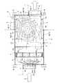
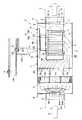
図1は、本実施形態に係る本発明の中間ダクトファンを示す横断面図であり、図2は、同中間ダクトファンの縦断面図であり、図3は、同中間ダクトファンを、レンジフードから天井裏などの空間を通して屋外の排気口にわたり配管される送風ダクトと配管途中に設置したときの一例を示す概略図であり、図4は、レンジフードの一例を示す縦断面図である。
ここでは、中間ダクトファンAの設置形態として、図3に示すように、屋内(室内)に設置されるレンジフードBから天井裏Cなどの空間を通して屋外(室外)の外壁などに設けられる排気口3とにわたり配管されて、調理中に発生する排気流Gが通る送風ダクト1の配管途中に中間ダクトファンAを設置した例を挙げて説明する。Hereinafter, embodiments of the present invention will be described in detail with reference to the drawings as appropriate.
FIG. 1 is a transverse sectional view showing an intermediate duct fan of the present invention according to the present embodiment, FIG. 2 is a longitudinal sectional view of the intermediate duct fan, and FIG. 3 shows the intermediate duct fan as a range hood. FIG. 4 is a schematic view showing an example of a fan duct that is piped over an outdoor exhaust port through a space such as the ceiling and the middle of the pipe, and FIG. 4 is a longitudinal sectional view showing an example of a range hood.
Here, as an installation mode of the intermediate duct fan A, as shown in FIG. 3, an exhaust port provided on an outdoor (outdoor) outer wall or the like through a space such as a ceiling hood C from a range hood B installed indoors (indoor). An example in which the intermediate duct fan A is installed in the middle of the piping of the
≪中間ダクトファンの構成≫
中間ダクトファンAは、図1および図2に示すように、ケース体4と、このケース体4内に内設される空気流清浄フィルタとしての脱臭フィルタ5および電動送風機6とを備えて構成されている。≪Configuration of intermediate duct fan≫
As shown in FIGS. 1 and 2, the intermediate duct fan A includes a case body 4, and a
≪ケース体の構成≫
ケース体4は、適宜の容積を有する平面視で略矩形形状に形成されている。
そして、このケース体は、図1および図2に示すように、ケース壁の短辺一側に吸込み口4aを備えている。これにより、図に示すように、レンジフードBから天井裏Cなどの空間に引き込まれて配管される上流側の送風ダクト1が接続口具2を介して接続されるように形成されている。≪Case body structure≫
The case body 4 is formed in a substantially rectangular shape in plan view having an appropriate volume.
As shown in FIGS. 1 and 2, the case body includes a
また、ケース体4は、図1および図2に示すように、ケース壁の短辺他側と、長辺両側との三方向に吐出し口4b−1,4b−2,4b−3をそれぞれ備え、外壁の排気口3にわたり配管される下流側の送風ダクト1が選択されたいずれか一ヶ所の吐出し口4b−1,4b−2,4b−3に接続口具2を介して接続されるように形成されている。
つまり、いずれか一ヶ所の吐出し口4b−1,4b−2,4b−3に接続される下流側の送風ダクト1は、外壁の排気口3に向けて配管されるときに、排気流Gの圧力損失などを抑えた略直線的な配管形態とすることが望ましい。しかし、建物の間取りなどによっては、図1および図2に実線で示す接続口具2が取り付けられている短辺他側のみにしか吐出し口4b−1が備えられていない場合、該吐出し口4b−1から排気口3に向けて配管される下流側の送風ダクト1を、その配管途中などにおいて略直角に蛇行させた配管形態を取らざる得ない中間ダクトファンAの設置環境がある。
このような設置環境において、外壁の排気口3に向けて配管される下流側の送風ダクト1の配管方向に合わせて選択できる三方向の吐出し口4b−1,4b−2,4b−3がケース体4に備えられていることで、下流側の送風ダクト1を蛇行させることなく、略直線的な配管形態にて配管することが可能になり、有効である。
この場合、使用しない残る二方向(2ヶ所)の吐出し口4b−2,4b−3は、図1に示すように、ビス止めなどによって取り付けられる閉鎖蓋7にて密閉される。
なお、接続口具2は、送風ダクト1の配管方向に合わせて三方向の吐出し口4b−1,4b−2,4b−3のいずれか一ヶ所に対し、ビス止めなどによって付け替えられるようになっている。As shown in FIGS. 1 and 2, the case body 4 has
That is, when the
In such an installation environment, there are three-
In this case, the remaining two-way (two places)
In addition, the
また、三方向の吐出し口4b−1,4b−2,4b−3がケース体4に備えられていることで、レンジフードBから天井裏Cに引き込まれて配管される上流側の送風ダクト1においても蛇行させることなく、略直線的な配管形態にて配管することが可能になり、有効である。 Further, since the three-
また、ケース体4は、天井裏Cにおいて、例えば、2階部分の床壁の裏面などにビス止めや吊ボルトなどによって取り付けられる取付金具8を四隅コーナーにそれぞれ備えている。
これにより、ケース体4は、図1〜図3に示すように、天井裏Cなどの空間にビス止めや吊ボルトなどによって設置され、吸込み口4aに上流側の送風ダクト1が、そして選択された一ヶ所の吐出し口4b−1に下流側の送風ダクト1がそれぞれ接続口具2を介して接続されるようになっている。In addition, the case body 4 includes, in the back of the ceiling C, for example, mounting
Thereby, as shown in FIGS. 1 to 3, the case body 4 is installed in a space such as the ceiling back C by screws or suspension bolts, and the
また、ケース体4は、図2に示すように、ケース壁の下面側が蓋体9によって開閉可能に形成されている。これにより、天井などに設けられている図示省略の点検口を開け、蓋体9を取り外すことによって、脱臭フィルタ5を洗う、または、新規のものと交換するなどのときに、ケース体4内から脱臭フィルタ5を取り出すことができるようにしている。 As shown in FIG. 2, the case body 4 is formed such that the lower surface side of the case wall can be opened and closed by a lid body 9. Thus, when the
≪脱臭フィルタの構成≫
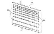
図5は、脱臭フィルタの一例を示す斜視図である。ここでは、図1および図2を適宜参照しながら説明する。
脱臭フィルタ5は、図5に示すように、ケース体4内を吸込み口4a側と吐出し口4b側とに仕切ることができる大きさで、適宜の厚さを有する格子状の支持枠5aと、この支持枠5a内に略碁盤目状に並列させて配置される脱臭材5bとで構成されている。
支持枠5aは、図5示すように、複数の脱臭材5bを収める凹み10を略碁盤目状に並列させて備えているケース部5a−1と、このケース部5a−1の各凹み10に脱臭材5bを収めた後に、ケース部5a−1を閉蓋する蓋部5a−2とで構成されている。≪Configuration of deodorizing filter≫
FIG. 5 is a perspective view showing an example of a deodorizing filter. Here, description will be made with reference to FIGS. 1 and 2 as appropriate.
As shown in FIG. 5, the
As shown in FIG. 5, the
≪脱臭材の構成≫
脱臭材5bは、支持枠5aの凹み10に合わせた略四角形状(略ブロック形状)に形成されている。
この脱臭材5bは、含水珪酸マグネシウム粘土鉱物を主成分とする脱臭材料を用いて形成されている多孔質材料(構造体)、または光触媒或いは熱触媒などから形成されている。
例えば、多孔質材料の例を具体的に説明するならば、アタパルジャイト20〜90重量部、セピオライト20〜90重量部、骨材としてシリカ20〜90重量部、バインダーとしてメチルセルロース数重量部を、湿式により混練させて押出し成形などによって成形した後に、乾燥してから、500℃以下で焼成した連続ハニカム構造体(連続多孔構造)としている(図5の拡大図参照)。
これにより、脱臭表面積を大きく確保し、排気流G中に含まれている臭気成分を脱臭性能(分解作用)によって除去するようにしている。≪Deodorant composition≫
The
The
For example, if an example of a porous material is specifically described, 20 to 90 parts by weight of attapulgite, 20 to 90 parts by weight of sepiolite, 20 to 90 parts by weight of silica as an aggregate, and several parts by weight of methylcellulose as a binder are wet-treated. A continuous honeycomb structure (continuous porous structure) is obtained by kneading and forming by extrusion or the like, then drying and firing at 500 ° C. or lower (see an enlarged view of FIG. 5).
Thereby, a large deodorizing surface area is ensured, and the odor components contained in the exhaust stream G are removed by the deodorizing performance (decomposing action).
なお、図示を省略しているが、脱臭フィルタ5は、ネジ止めやその他の取付手段によってケース体4内の定位置に着脱可能に配置されるように形成されている。
また、脱臭材5bが、光触媒を主成分とする脱臭材料を用いて形成されて場合には、ケース体4内に備えられている図示省略のブラックライトなどの光源および反射板から照射される紫外線によって、光触媒粉末による分解作用で排気流G中に含まれている臭気成分が除去されるようにする。In addition, although illustration is abbreviate | omitted, the
Further, in the case where the
≪電動送風機の構成≫
電動送風機6は、周知の構造を呈している。
すなわち、図1および図2に示すように、ボリュート形状に形成されているファンケーシング6aにファンモータ(交流モータ)6bを略同軸直立状に取り付けている。そして、ファンケーシング6a内に、モータボディーとともに略同軸状に臨ませたファンモータ6bのモータ軸には、排気ファン6cが取り付けられている周知の構造である。排気ファン6cは、シロッコファンである。
また、電動送風機6は、図1および図2に示すように、ファンケーシング6aの一側壁面に、ベルマウス11を取り付けることによってモータ軸と同芯線上にて略ラッパ口形状に開口される吸引口12を備えている。
また、排気ファン6cの回転方向におけるファンケーシング6aの一側に、ケース体4のいずれか一ヶ所の吐出し口4b−1,4b−2,4b−3に接続される排気口13を備えている。≪Configuration of electric blower≫
The
That is, as shown in FIGS. 1 and 2, a fan motor (AC motor) 6b is attached to a
Further, as shown in FIGS. 1 and 2, the
Further, an
このように形成されている電動送風機6は、図1および図2に実線および二点鎖線で示すように、三方向の吐出し口4b−1,4b−2,4b−3のうち、選択された一ヶ所にファンケーシング6aの排気口13を接続させ、なおかつ、吸引口12を蓋体9によって開閉されるケース体4のケース壁下面側に向けた下向き開口状態で、後記する支持部材14を介してケース体4内に内設される。
これにより、下向きに開口する吸引口12に発生する吸引力が、脱臭フィルタ5を通してケース体4の吸込み口4a側に伝播され、レンジフードBのフード電動送風機16の吸引口17に発生する吸引力によってレンジフードB内に吸込み捕集される調理中の排気流Gが上流側の送風ダクト1を通してケース体4内に吸い込まれる。
そして、吸込み口4aからケース体4内に流入された排気流Gは、脱臭フィルタ5を通過して電動送風機6が配置されている下流側空間18側に流れ、ファンケーシング6aの吸引口12からファンケーシング6a内に吸気される。ファンケーシング6a内に吸気された排気流Gは、ケース体4の吐出し口4b−1に接続されているファンケーシング6aの排気口13から下流側の送風ダクト1内に吐き出され、該送風ダクト1を通って排気口3から屋外に排気される。The
As a result, the suction force generated at the
Then, the exhaust flow G flowing into the case body 4 from the
電動送風機6をケース体4内に支持(吊持)するための支持部材14は、図1および図2に示すように、ケース体4側に止めネジ19によって着脱自在に取り付けられるベース部14aと、ファンケーシング6a側にスポット溶接などによって固着されて、支持ベース14aに止めネジ20によって着脱自在に取り付けられる支持ブラケット14bとで構成されている。 As shown in FIGS. 1 and 2, the
支持ベース14aは、ボリュート形状のファンケーシング6aの大きさに相当する程度の大きさを有する平面視で略矩形形状を呈し、略クランク形状に折り曲げられている短辺両側部が、ケース体4の内側に止めネジ19によって取り付けられるように形成されている。
また、支持ベース14aは、図1に破線(点線)および二点鎖線で示すように、支持ブラケット14bを90°向きを変えて取り付けることができるように、それぞれの向きに4ヶ所、計8ヶ所にネジ挿通孔21をそれぞれ備えている。The
In addition, as shown by a broken line (dotted line) and a chain double-dashed line in FIG. 1, the
支持ブラケット14bは、図2に示すように、ファンモータ6bを包囲しえる大きさと深さを有する断面視で略コの字形状を呈し、略L字形状に折り曲げられている短辺縁部が、ファンケーシング6aにスポット溶接などによって固着されるように形成されている。
そして、支持ブラケット14bは、支持ベース14aの設けられている4ヶ所の各ネジ挿通孔21にそれぞれ対応させた位置にネジ孔22をそれぞれ備えている。As shown in FIG. 2, the
The
このように形成されている支持ベース14aと支持ブラケット14bとからなる支持部材14によって、電動送風機6は、前記したように、ケース体4の選択された一ヶ所の吐出し口4b−1,4b−2,4b−3にファンケーシング6aの排気口13を接続させ、なおかつ、吸引口12を蓋体9によって開閉されるケース体4のケース壁下面側に向けた下向きの開口状態で、後記する支持部材14を介してケース体4内に内設される。
つまり、中間ダクトファンAの設置環境に応じた送風ダクト1の配管方向に合わせてファンケーシング6aの排気口13を、ケース体4の選択されたいずれか一ヶ所の吐出し口4b−1,4b−2,4b−3に接続させた状態で、電動送風機6をケース体4内に内設させることができる。As described above, the
That is, the
また、中間ダクトファンAは、図1および図2に示すように、ケース体4内の下流側空間18における脱臭フィルタ5と電動送風機6との間に、電動送風機6の吸引口12に発生する吸込み力が脱臭フィルタ5の全域に行き渡るように、吸込み力を分配させるための分配部材23を備えている。
さらに、中間ダクトファンAは、図1および図2に示すように、ケース体4内の吸込み口4aと脱臭フィルタ5との間に、電動送風機6の吸引口12に発生する吸込み力によって吸込み口からケース体内に流入された排気流が、脱臭フィルタの全域に行き渡るように、排気流を分散させる分散部材24を備えている。Further, as shown in FIGS. 1 and 2, the intermediate duct fan A is generated at the
Further, as shown in FIGS. 1 and 2, the intermediate duct fan A has a suction port formed by a suction force generated at the
≪分配部材の構成≫
図6は、本実施形態に係る分配部材を示す斜視図である。ここでは、図1および図2を適宜参照しながら説明する。
分配部材23は、図1および図2、図6に示すように、板材を用いてケース体4内の下流側空間18を脱臭フィルタ5側と電動送風機6側とに仕切る程度の大きさを有する矩形形状に形成され、多数の通孔25を略碁盤目状に備えている。≪Configuration of distribution member≫
FIG. 6 is a perspective view showing a distribution member according to the present embodiment. Here, description will be made with reference to FIGS. 1 and 2 as appropriate.
As shown in FIGS. 1, 2, and 6, the
通孔25は、図2および図6に示すように、ケース体4の下面側(蓋体9側)に位置する電動送風機6の吸引口12側からケース体4の上面側に至るにしたがって開口個数が徐々に増えるように、開口間隔を徐々に狭くした配列にて備えられている。 2 and 6, the through
このように形成されている分配部材23は、ビス止めやその他の止め手段によってケース壁に取り付けられて、図1および図2に示すように、ケース体4内の下流側空間18における脱臭フィルタ5と電動送風機6との間に配置される。
これにより、ケース体4の下面側よりも上面側に至るにしたがって通孔25群による排気流Gの流通開口面積を大きくすることで、図2に示すように、電動送風機6の吸引口12に発生する吸引力が脱臭フィルタ5の全域に行き渡り伝播されるようにしている。The
Thereby, as shown in FIG. 2, the
なお、図示を省略しているが、多数の通孔25を、分配部材23に千鳥状の配列にて備えることができる。
また、通孔25の口径を、ケース体4の下面側(蓋体9側)に位置する電動送風機6の吸引口12側からケース体4の上面側に至るにしたがって大きくするなどによって、電動送風機6の吸引力が脱臭フィルタ5の全域に行き渡り伝播されるようにすることができる。つまり、通孔25の口径を変えるによって、ケース体4の下面側よりも上面側に至るにしたがって通孔15群による排気流Gの流通開口面積を大きくすることができる。
また、通孔25の形状としては、円形に限らず、四角形、長方形など任意である。また、電動送風機6の吸引力が各通孔25を通して脱臭フィルタ5の全域に行き渡りスムーズに伝播されるように、通孔25の孔縁を脱臭フィルタ5側に向けて湾曲させた略ラッパ形状とすることができる。Although not shown, a large number of through
The diameter of the through
In addition, the shape of the through
≪分散部材の構成≫
図7は、本実施形態に係る分散部材を示す斜視図である。ここでは、図1および図2を適宜参照しながら説明する。
分散部材24は、図1および図2に示すように、ケース体4の吸込み口4aから脱臭フィルタ5の方向に向けて末広がるように形成されている内外二重のガイド部材24a,24bから構成されている。
ガイド部材24a,24bは、図1および図2、図7に示すように、吸込み口4aと脱臭フィルタ5にそれぞれ対面する両面を、それぞれの対面形状に開口させた略台形形状に形成されている。
詳しく説明すると、吸込み口4aに対面する側の開口を、吸込み口4aの口径よりも小さく、なおかつ、口径をそれぞれ変えた円形形状に、そして脱臭フィルタ5に対面する側の開口を、脱臭フィルタ5よりも一回りほど小さく、なおかつ、口径をそれぞれ変えた略矩形形状に形成されている。≪Configuration of dispersion member≫
FIG. 7 is a perspective view showing a dispersion member according to the present embodiment. Here, description will be made with reference to FIGS. 1 and 2 as appropriate.
As shown in FIGS. 1 and 2, the
As shown in FIGS. 1, 2, and 7, the
Explaining in detail, the opening on the side facing the
そして、このように両面開口の略台形形状に形成されているガイド部材24a,24bは、図示省略の連結部材による三点または四点による連結によって互いの間に排気流Gを通す流通隙間を確保した状態で内外二重となっている。
なお、連結部材としては、排気流Gが脱臭フィルタ5側に向けて流れるときの圧力損失(気流抵抗)を抑える細めの棒材やパイプ材、或いはそれに類似した部材を用いることが好ましい。
また、内外二重のガイド部材24a,24bからなる分散部材24は、吸込み口4aが設けられているケース体4の短辺一側や長辺四面に、図示省略の支持部材による三点または四点による支持によって取り付けられることで、図1および図2に示すように、ケース体4内における吸込み口4aと脱臭フィルタ5との間に配置される。
これにより、電動送風機6の吸引力によって吸込み口4aからケース体4に吸い込まれる排気流Gが、図1および図2に示すように、内外二重のガイド部材24a,24bからなる分散部材24によって脱臭フィルタ5の全域に行き渡り分散されるようにしている。The
In addition, as a connection member, it is preferable to use a thin bar material, pipe material, or a similar member that suppresses pressure loss (air flow resistance) when the exhaust flow G flows toward the
Further, the dispersing
Thus, the exhaust flow G sucked into the case body 4 from the
なお、図示を省略しているが、分散部材24は、内外二重に限らず、三重、四重など任意であり、また、平板を用いた分割タイプにて構成することができる。 In addition, although illustration is abbreviate | omitted, the dispersion |
以上のように構成されている中間ダクトファンAは、図3に示すように、天井裏Cに通して屋内(台所)のレンジフードBから屋外の排気口3にわたり配管される送風ダクト1の配管途中に、ケース体の吸込み口4a、送風ダクト1の配管方向に合わせて選択された吐出し口4b−1を接続させて設置される。
そして、ケース体4内に内設されている電動送風機6は、レンジフードBの後記するフード体26の前面に備えられる運転操作部29に図示省略のリード線などによって接続され、運転操作部29の運転ON/OFF切り替え操作によって運転される排気電動送風機27の運転(高速運転、中速運転、低速運転)に同調して運転するようになっている。As shown in FIG. 3, the intermediate duct fan A configured as described above is connected to the
The
なお、運転操作部29の運転ON/OFF切り替え操作による電動送風機6の運転開始、運転停止を、リード線などを用いた有線方式に変えて、送受信ユニットを用いた無線方式とすることができる。つまり、運転操作部29側に発信ユニットを備え、電動送風機6側に受信ユニットを備えることで、排気電動送風機27の運転(高速運転、中速運転、低速運転)に同調させて電動送風機6を運転させることができる。 Note that the operation start and operation stop of the
≪レンジフードの構成≫
ここでは、図3および図4を適宜参照しながら説明する。
レンジフードBは、周知の深型タイプのレンジフードある。
すなわち、図3および図4に示すように、深型のフード体26内におけるキッチン壁K−1側に位置させて排気電動送風機27を縦置きに設置することにより、排気電動送風機27の前方(前側)で、高さ方向(キッチン天井K−2の高さ方向)に深く、下向きに開口させた排気流Gの捕獲空間28形成されるようにしている。
これにより、調理中に発生し、レンジフードBに向けて舞い上がってくる排気流Gが、排気電動送風機27の吸込み力により捕獲空間28に吸込み捕獲され、排気電動送風機27に接続されて天井裏Cの空間に配管されている送風ダクト1を通り、送風ダクト1の配管途中の中間ダクトファンA内を通過して屋外の排気口3から排気されるようになっている。≪Configuration of range hood≫
Here, description will be made with reference to FIGS. 3 and 4 as appropriate.
Range hood B is a well-known deep type range hood.
That is, as shown in FIG. 3 and FIG. 4, the exhaust
Thus, the exhaust flow G generated during cooking and rising toward the range hood B is sucked and captured in the
排気電動送風機27は、フード体26の前面に備えられている運転操作部29に図示省略のリード線などによって接続されており、運転操作部29の運転ON/OFF切り替え操作、そして高速運転、中速運転、低速運転の強弱三段階に切り替えられて運転するようになっている。
すなわち、運転操作部29には、排気電動送風機27を高速運転、中速運転、低速運転のいずれかで運転を開始させるための高速用スイッチ、中速用スイッチ、低速用スイッチの各運転ONスイッチ、そして排気電動送風機27の運転を停止させるための運転OFFスイッチがそれぞれ備えられている。
そして、運転操作部29の各運転ONスイッチが操作されたとき、後記する運転回路30を介して排気電動送風機27が運転を開始し、運転OFFスイッチが操作されたときに、運転回路30を介して排気電動送風機27の運転が停止するようになっている。The exhaust
That is, the driving
When each operation ON switch of the
また、レンジフードBは、図4に示すように、排気電動送風機27の前方で、フード体26内を、排気電動送風機27側と捕獲空間28側とに仕切るようにグリスフィルタ31を備えている。
これにより、捕獲空間28に吸い込み捕獲された排気流Gが、排気電動送風機27の吸引力によりグリスフィルタ31を通過して排気電動送風機27側に流れるときに、排気流G中に含まれている油脂成分がグリスフィルタ31によって除去(捕獲)されるようになっている。As shown in FIG. 4, the range hood B includes a
Thus, when the exhaust flow G sucked and captured in the
さらに、レンジフードBは、グリスフィルタ31の下端縁を係脱自在に支持するように、グリスフィルタ30の下端縁位置から排気電動送風機27の下方に至るフード体26の前後方向において、該フード体26の下向き開口側と排気電動送風機27側とを仕切るように仕切りパネル32を備えている。 Further, the range hood B is disposed in the front-rear direction of the
[中間ダクトファンの作用説明]
次に、図3に示すように、屋内のレンジフードBから天井裏Cの空間を通して屋外の排気口3にわたり配管される送風ダクト1の配管途中に設置されて使用される中間ダクトファンAについて簡単に説明する。ここでは、図1および図2を適宜参照しながら説明する。
レンジフードBの運転操作部29の運転ON操作によって排気電動送風機27の運転(高速運転、中速運転、低速運転のいずれか)が開始すると、排気電動送風機27の運転に同調して中間ダクトファンAの電動送風機6も運転を開始する。例えば、排気電動送風機27が中速運転により運転を開始するときには電動送風機6も中速運転により運転を開始する。
これにより、レンジフードBから上流側の送風ダクト1を通って中間ダクトファンAのケース体4内に吸い込まれ、このケース体4内から下流側の送風ダクト1を通って屋外に排気される排気流Gの流れはスムーズに行われる。つまり、調理中に発生する排気流Gを吸い込み捕集し、送風ダクト1を通して屋外に排気するレンジフードBの排気性能の低下を防ぐことができる。[Explanation of intermediate duct fan action]
Next, as shown in FIG. 3, the intermediate duct fan A that is installed and used in the middle of the piping of the
When the operation of the exhaust electric blower 27 (high speed operation, medium speed operation, or low speed operation) is started by the operation ON operation of the
As a result, the exhaust is exhausted from the range hood B through the
そして、図1および図2に示すように、電動送風機6の吸引力によって吸込み口4aからケース体4内に吸い込まれた排気流Gは、吸込み口4aから脱臭フィルタ5の全域に行き渡るように分散される分散部材24の分散作用と、電動送風機6の吸引力を脱臭フィルタ5の全域に行き渡り伝播させるように分配される分配部材23の分配作用との相乗作用によって、脱臭フィルタ5の全域を通過してケース体4内の下流側空間18側に流れる。
これにより、ケース体4内に吸い込まれた排気流Gを脱臭フィルタ5の全域において通過させながら、排気流G中の臭気成分を効率的に除去することができる。つまり、臭気成分が脱臭され、略無臭化状態まで清浄化された排気流Gとして屋外に排気させることができる。
しかも、排気流Gが、脱臭フィルタ5の部分的な場所のみ、例えば、電動送風機6の吸引口12が位置する脱臭フィルタ5の下半部側のみを通過し、当該下半部側のみによって臭気成分の除去が行われることを防ぐことができる。つまり、脱臭フィルタ5の下半部側のみが臭気成分によって目詰まりを引き起こすことを防ぐことができる。As shown in FIGS. 1 and 2, the exhaust flow G sucked into the case body 4 from the
Thereby, the odor component in the exhaust gas G can be efficiently removed while the exhaust gas G sucked into the case body 4 is allowed to pass through the entire area of the
Moreover, the exhaust flow G passes through only a part of the
そして、本実施形態では、以上のように構成されている中間ダクトファンAの脱臭フィルタ5の目詰まりを監視するための目詰まり監視装置(以後、「監視装置」と称する)を備えている。 And in this embodiment, the clogging monitoring apparatus (henceforth a "monitoring apparatus") for monitoring clogging of the
≪第1の実施形態に係る監視装置の構成≫
図8は、第1の実施形態に係る監視装置の概略構成を示す機能ブロック図である。ここでは、図1〜図4を適宜参照しながら説明する。
監視装置Dは、中間ダクトファンAの運転中に、脱臭フィルタ5(脱臭材5b)の目詰まり状態(度合い)を監視し、脱臭フィルタ5に目詰まりが発生した(例えば、全く目詰まりがないクリーンな状態から目詰まり度合いが60%になった)ときに、脱臭フィルタ5が目詰まり状態であることを使用者に知らせるように構成されている。<< Configuration of Monitoring Device According to First Embodiment >>
FIG. 8 is a functional block diagram illustrating a schematic configuration of the monitoring apparatus according to the first embodiment. Here, it demonstrates, referring suitably FIGS. 1-4.
The monitoring device D monitors the clogged state (degree) of the deodorizing filter 5 (
監視装置Dは、図8に示すように、排気流Gの静圧を検出する圧力検出手段としての圧力検出センサ33と、この圧力検出センサ33により検出された検出静圧値Pnに基づいて脱臭フィルタ5の目詰まり度合いを判定し、かつ、脱臭フィルタ5が目詰まり状態にあると判定したときには使用者に報知するマイクロコンピュータ34とを備えて構成されている。As shown in FIG. 8, the monitoring device D is based on a
マイクロコンピュータ34には、図8に示すように、圧力検出センサ33により検出された検出静圧値Pnと、予め定められている設定静圧値Pとを比較する判定手段35、この判定手段35により静圧に変化があると判定されたときに、動作を開始して時間を累積(カウント)するタイマ手段36、このタイマ手段36による累積時間TΣnが、予め定められている設定時間Tに達するか、この設定時間Tを越えたときに、脱臭フィルタ5に目詰まりが発生し、脱臭フィルタ5の保守時期であることを使用者に報知する報知手段37、これらの各機能などが内蔵されている。
圧力検出センサ33、判定手段35、タイマ手段36、報知手段37は中間ダクトファンAの運転中に機能するように設定されている。As shown in FIG. 8, the
The
≪圧力検出センサの構成≫
圧力検出センサ33は、ベンチュリ管やピトー管、或いはブルドン管、さらにダイアフラム式圧力センサなどからなり、中間ダクトファンAの電動送風機6が運転中に、排気流Gの静圧を検出し、その検出された検出静圧値Pnを判定手段12に出力するように構成されている。
この圧力検出センサ33は、図1および図2に示す中間ダクトファンAのケース体4内における脱臭フィルタ5の下流側空間(送風機設置空間)18内に配置され、脱臭フィルタ5を通過して下流側空間18内に流れてくる排気流Gの静圧を検出するようになっている。
つまり、脱臭フィルタ5の目詰まりが進行すると、送風ダクト1内および中間ダクトファンAのケース体4内の排気流Gの静圧に変化が生じる。これにより、排気流Gの静圧の変化を検出することにより、脱臭フィルタ5の目詰まり情報を正確に得ることができる。≪Configuration of pressure detection sensor≫
The
The
That is, when the clogging of the
また、圧力検出センサ33は、所定の時間間隔Δt、例えば、約1〜4秒の間隔をおいて静圧の検出を実行するように、図示省略の検出回路に設定されている。 The
なお、圧力検出センサ33を、電動送風機6の下流側における送風ダクト1内や脱臭フィルタ5の上流側(ケース体4の吸込み口4a側)に配置し、排気流Gの静圧を検出するようにすることもできる。 The
≪判定手段の構成≫
判定手段35は、中間ダクトファンA(電動送風機6)の運転中に、圧力検出センサ33から出力されてくる検出静圧値Pnと設定静圧値Pとを比較し、検出静圧値Pnが設定静圧値Pよりも小さいときに脱臭フィルタ5に目詰まりが発生していると判定し、タイマ手段36にカウント信号を出力するように構成されている。
また、判定手段35は、中間ダクトファンBの運転中において、圧力検出センサ33から所定の時間間隔Δtにて出力されてくる検出静圧値Pnと設定静圧値Pとを継続的に比較することを実行し、検出静圧値Pnが設定静圧値Pより小さいか、大きいかを判定するように構成されている。<< Configuration of judgment means >>
The
Further, the
また、判定手段35は、レンジフードBの排気電動送風機27の運転に同調して運転する中間ダクトファンAの電動送風機6が、高速運転のとき、中速運転のとき、低速運転のときのそれぞれの運転ときにおいて圧力検出センサ33から出力されてくる検出静圧値Pnと比較するための高速用、中速用、低速用それぞれの設定静圧値Pを備え、それぞれの運転に合わせて検出静圧値Pnとの比較を実行し、脱臭フィルタ5に目詰まりが発生している否かを判定するように構成されている。
例えば、判定手段35は、高速用設定静圧値P−1、中速用設定静圧値P−2、低速用設定静圧値P−3をそれぞれ備えている。これにより、中間ダクトファンAが中速運転のときには、圧力検出センサ33から出力されてくる検出静圧値Pnと、中速用設定静圧値P−2とを継続的に比較することを実行し、検出静圧値Pnが設定静圧値P−2より小さいか、大きいかを判定するように構成されている。In addition, the determination means 35 is used when the
For example, the
≪タイマ手段の構成≫
タイマ手段36は、判定手段35からカウント信号が入力されてきた時点で動作を開始し、時間の累積(カウント)を開始するように構成されている。
また、タイマ手段36は、判定手段35からのカウント信号が所定の時間間隔Δtにて途切れることなく出力されてくる間において時間の累積を続け、この累積時間TΣnが、予め定められている設定時間Tに達するか、それを越えた時点で、報知手段37に報知信号を出力するように構成されている。
ここで、累積時間TΣnは、判定手段35からカウント信号が出力されてくる所定の時間間隔Δtと、前回までに判定手段35から出力されてきたカウント信号の出力累積時間TΣn−1との累積である。≪Configuration of timer means≫
The timer means 36 is configured to start operation when a count signal is input from the determination means 35 and start time accumulation (counting).
The timer means 36 continues to accumulate time while the count signal from the judging means 35 is output without interruption at a predetermined time interval Δt, and this accumulated time TΣn is set in advance. When the time T is reached or exceeded, a notification signal is output to the notification means 37.
Here, the cumulative time TΣn is a predetermined time interval Δt at which the count signal is output from the
そして、タイマ手段36は、判定手段35から所定の時間間隔Δtをおいて出力されてくるカウント信号の累積時間TΣnが、設定時間Tに達する前に、カウント信号が途切れた場合には、累積時間TΣnがリセット(初期化)されるとともに動作が停止されるように構成されている。
例えば、設定時間Tを約60秒、所定の時間間隔Δtを2秒と仮定し、時間の累積を開始してから累積時間TΣnが8秒に達した時点で、判定手段35からタイマ手段36へのカウント信号の出力が途切れた場合、累積時間TΣn、8秒が0にリセットされ、なおかつ、タイマ手段36の動作が停止するように構成されている。
これにより、タイマ手段36は、判定手段35から新たにカウント信号が出力された時点で、動作を開始し、0から新たに時間の累積を開始することになる。When the count signal is interrupted before the accumulated timeTΣn of the count signal output from the determining means 35 at a predetermined time interval Δt reaches the set time T, the timer means 36 accumulates. The operation is stopped while the time TΣn is reset (initialized).
For example, assuming that the set time T is about 60 seconds and the predetermined time interval Δt is 2 seconds, the determination means 35 to the timer means 36 when the accumulated timeTΣn reaches 8 seconds after the time accumulation is started. When the output of the count signal is interrupted, the accumulated time TΣn , 8 seconds is reset to 0, and the operation of the timer means 36 is stopped.
As a result, the timer means 36 starts its operation when a new count signal is output from the judging means 35, and starts to accumulate time from zero.
このように構成されているタイマ手段36を用いることで、誤作動なく、脱臭フィルタ5の目詰まりの発生を、報知手段37の報知ランプ37−1を介して使用者に的確に、かつ、精度良く報知することができる。
つまり、圧力検出センサ33から継続して出力されてくる排気流Gの検出静圧値Pnと設定静圧値Pとの判定手段35による比較判定を、タイマ手段36に予め設定されている設定時間T内において数回繰り返すことで、圧力検出センサ33が静圧を検出する際のノイズを除去することができる。
これにより、判定手段35は、脱臭フィルタ5の目詰まりの発生を誤作動なく判定し、報知手段37に報知信号を出力し、報知ランプ37−1によって使用者に的確に、かつ、精度良く報知することができる。By using the timer means 36 configured in this manner, the occurrence of clogging of the
In other words, the comparison determination by the
Thereby, the determination means 35 determines the occurrence of clogging of the
≪報知手段の構成≫
報知手段37は、タイマ手段36から出力される報知信号を受けたときに、中間ダクトファンAの脱臭フィルタ5に目詰まりが発生していることを使用者に報知する役目を成すものである。
この報知手段37は、発光ダイオード,白熱電球,ハロゲンランプ,蛍光ランプ,HIDランプなどからなる報知ランプ37−1を備えている。これにより、報知ランプ37−1を点灯、または、点滅させることで、脱臭フィルタ5が目詰まり状態の保守時期であることを使用者に報知するように構成されている。
報知ランプ37−1は、図3および図4に示すレンジフードBの前面などに備えられて、報知手段37からの点灯指令を受けたときに点灯または点滅するようになっている。
また、報知ランプ37−1は、報知手段37から消灯指令により、または、運転操作部29の各スイッチ類と並設させて、該運転操作部29に備えられる図示省略の消灯釦を使用者が押すなどによって消灯するようになっている。≪Configuration of notification means≫
The notification means 37 serves to notify the user that the
The
The notification lamp 37-1 is provided on the front surface of the range hood B shown in FIGS. 3 and 4, and is lit or blinks when a lighting command is received from the notification means 37.
In addition, the notification lamp 37-1 is provided with a turn-off button (not shown) provided in the driving
[作用説明]
つぎに、以上のように構成されている第1の実施形態に係る監視装置Dによる中間ダクトファンAのフィルタ目詰まり監視について説明する。
図9は、監視装置による中間ダクトファン(脱臭フィルタ)の目詰まり監視動作の一例を示すフローチャートである。ここでは、図1〜図4を適宜参照しながら説明する。[Description of operation]
Next, filter clogging monitoring of the intermediate duct fan A by the monitoring device D according to the first embodiment configured as described above will be described.
FIG. 9 is a flowchart illustrating an example of the clogging monitoring operation of the intermediate duct fan (deodorizing filter) by the monitoring device. Here, it demonstrates, referring suitably FIGS. 1-4.
図4に示すレンジフードBの前面に備えられている運転操作部29の運転ON操作が成され、レンジフードBの排気電動送風機27を運転させると、排気電動送風機27の運転に同調して、図1および図2に示す中間ダクトファンAの電動送風機6が運転を開始する。
すると、レンジフードBの捕獲空間28に吸い込み捕集され、上流側の送風ダクト1を通って中間ダクトファンAのケース体4内に吸い込まれた排気流Gが、電動送風機6の吸引力によって脱臭フィルタ5を通過するとき、排気流G中の臭気成分は脱臭材5bによって脱臭される。
臭気成分が脱臭されて清浄化された排気流Gは、電動送風機6の吸引口12からファンケーシング6a内に吸気され、吐出し口4bに接続されている下流側の送風ダクト1を通って屋外の排気口3から排気される。When the operation ON operation of the
Then, the exhaust flow G sucked and collected in the
The exhaust stream G that has been deodorized and cleaned is sucked into the
このようにして、排気流G中の臭気成分が脱臭フィルタ5によって脱臭される中間ダクトファンBの運転中に、脱臭フィルタ5の下流側空間18において排気流Gの静圧が監視装置によって監視されている。
詳しくは、中間ダクトファンAの運転中、脱臭フィルタ5を通過して下流側空間18に流れた排気流Gの静圧が圧力検出センサ33によって検出され(ステップ38)、検出された検出静圧値Pnは、判定手段35へと出力される。判定手段35に検出静圧値Pnが入力されてくると、判定手段35による検出静圧値Pnと設定静圧値Pとを比較する判定が実行される(ステップ39)。このとき、圧力検出センサ33による検出と判定手段35による判定は、所定の時間間隔(例えば、約1〜4秒の間隔)Δtにて継続的に繰り返し行われる。
判定手段35によって、検出静圧値Pnが設定静圧値Pよりも小さいと判定(YESと判定)されると、タイマ手段36にカウント信号が出力される。タイマ手段36は、判定手段35からカウント信号が入力されてきた時点で、動作を開始し、時間の累積を実行する(ステップ40)。このとき、検出静圧値Pnが設定静圧値Pよりも大きいと判定(NOと判定)されると、ステップ38に戻され、設定時間Tに達していない累積時間TΣnはリセットされる(ステップ41)。In this way, during the operation of the intermediate duct fan B in which the odor component in the exhaust flow G is deodorized by the
Specifically, during operation of the intermediate duct fan A, the static pressure of the exhaust flow G that has passed through the
If the determination means 35 determines that the detected static pressure value Pn is smaller than the set static pressure value P (determined as YES), a count signal is output to the timer means 36. When the count signal is input from the
タイマ手段36による時間の累積が実行され、その累積時間TΣnが設定時間Tに達するか、それを越えると(ステップ42)、タイマ手段36から報知手段37に報知信号が出力される。報知手段37は、報知信号を受けて報知ランプ37−1を点灯させる(ステップ43)。Accumulation of time by the timer means 36 is executed, and when the accumulated timeTΣn reaches or exceeds the set time T (step 42), a notification signal is output from the timer means 36 to the notification means 37. The notification means 37 receives the notification signal and turns on the notification lamp 37-1 (step 43).
このように、第1の実施形態に係る監視装置Dによれば、図3に示すように、天井裏Cなどに設置されている中間ダクトファンAの臭気フィルタ5に目詰まりが発生すると、圧力検出センサ33による排気流Gの静圧の検出、判定手段35による検出静圧値Pnと設定静圧値Pとの比較判定、そしてタイマ手段36によるノイズの除去によって、的確に、精度良く、脱臭フィルタ5が目詰まりを発生したことを報知手段37(報知ランプ37−1の点灯)にて使用者に知らせることができる。Thus, according to the monitoring device D according to the first embodiment, as shown in FIG. 3, when clogging occurs in the
≪第2の実施形態に係る監視装置の構成≫
図10は、第2の実施形態に係る監視装置の概略構成を示す機能ブロック図である。ここでは、図1および図2を適宜参照しながら説明する。
なお、この第2の実施形態に係る監視装置D−1は、脱臭フィルタ5の目詰まりの発生を検出する検出手段として、排気流Gの風量を検出する風量検出センサ44を用いて構成した以外の構成要素においては、前記の第1の実施形態に係る監視装置Dと基本的に同じことから同じ構成要素に同じ符合を付することで重複説明は省略する。<< Configuration of Monitoring Device According to Second Embodiment >>
FIG. 10 is a functional block diagram illustrating a schematic configuration of the monitoring apparatus according to the second embodiment. Here, description will be made with reference to FIGS. 1 and 2 as appropriate.
The monitoring device D-1 according to the second embodiment is configured by using an air
すなわち、監視装置D−1は、図10に示すように、排気流Gの風量を検出する風量検出手段である風量検出センサ44と、この風量検出センサ44により検出された検出風量値Qnに基づいて脱臭フィルタ5の目詰まり度合いを判定し、かつ、脱臭フィルタ5が目詰まり状態にあると判定したきには使用者に報知するマイクロコンピュータ34とを備えて構成されている。That is, as shown in FIG. 10, the monitoring device D-1 uses an air
マイクロコンピュータ34には、図10に示すように、風量検出センサ44により検出された検出風量値Qnと、予め定められている設定風量Qとを比較する判定手段35、この判定手段35により風量に変化があると判定されたときに、動作を開始して時間を累積(カウント)するタイマ手段36、このタイマ手段36による累積時間TΣnが、予め定められている設定時間Tに達するか、この設定時間Tを越えたときに、脱臭フィルタ5に目詰まりが発生し、脱臭フィルタ5の保守時期であることを、報知ランプ37−1を点灯させることで使用者に報知する報知手段37、これらの各機能などが内蔵されている。As shown in FIG. 10, the
≪風量検出センサの構成≫
風量検出センサ44は、しぼり式流量計、差圧式流量計、フロート式流量計、熱線式流量計などからなり、中間ダクトファンAの電動送風機6が運転中に、排気流Gの風量を検出し、その検出した検出風量値Qnを判定手段35に出力するように構成されている。
この風量検出センサ44は、図1および図2に示す中間ダクトファンAのケース体4内における脱臭フィルタ5の下流側空間15内に配置され、脱臭フィルタ5を通過して下流側空間18内に流れてくる排気流Gの風量を検出するようになっている。≪Configuration of air volume detection sensor≫
The air
This air
また、この風量検出センサ44は、第1の実施形態において詳述の圧力検出センサ33と同じく、所定の時間間隔Δt、例えば、約1〜4秒の間隔をおいて風量の検出を実行するように構成されている。つまり、マイクロコンピュータ34のメモリ(図示省略)に入力されている制御プログラムによって所定の時間間隔Δtをおいて下流側空間18における排気流Gの風量を検出するようになっている。 The air
[作用説明]
つぎに、以上のように構成されている第2の実施形態に係る監視装置D−1による中間ダクトファンAのフィルタ目詰まり監視について説明する。
図11は、第2の実施形態に係る監視装置による中間ダクトファン(脱臭フィルタ)の目詰まり監視動作の一例を示すフローチャートである。ここでは、図3を適宜参照しながら説明する。[Description of operation]
Next, filter clogging monitoring of the intermediate duct fan A by the monitoring device D-1 according to the second embodiment configured as described above will be described.
FIG. 11 is a flowchart illustrating an example of the clogging monitoring operation of the intermediate duct fan (deodorizing filter) by the monitoring device according to the second embodiment. Here, description will be made with reference to FIG. 3 as appropriate.
中間ダクトファンAの運転中、脱臭フィルタ5を通過して下流側空間18に流れた排気流Gの風量が風量検出センサ44によって検出され(ステップ45)、検出された検出風量値Qnは、判定手段35へと出力される。判定手段35に検出風量値Qnが入力されてくると、判定手段35による検出風量値Qnと設定静圧値Qとを比較する判定が実行される(ステップ46)。このとき、風量検出センサ44による検出と判定手段35による判定は、所定の時間間隔(例えば、約1〜4秒の間隔)Δtにて継続的に繰り返し行われる。During the operation of the intermediate duct fan A, the air volume of the exhaust flow G flowing through the
判定手段35によって、検出風量値Qnが設定風量値Qに達するか、それよりも小さいと判定(YESと判定)されると、タイマ手段36にカウント信号が出力される。タイマ手段36は、判定手段35からカウント信号が入力されてきた時点で、動作を開始し、時間の累積を実行する(ステップ47)。このとき、検出風量値Qnが設定値静圧Qよりも大きいと判定(NOと判定)されると、ステップ45に戻される。このとき、設定時間Tに達していない累積時間TΣnはリセットされる(ステップ48)。The determining means 35, whether the detected air amount value Qn reaches the set air amount value Q, when it is small and the determination (YES as determination) than the count signal is output to the timer means 36. When the count signal is input from the
タイマ手段36による時間の累積が実行され、その累積時間TΣnが設定時間Tに達するか、それを越えると(ステップ49)、タイマ手段36から報知手段37に報知信号が出力される。報知手段37は、報知信号を受けて報知ランプ37−1を点灯させる(ステップ50)。Accumulation of time by the timer means 36 is executed, and when the accumulated timeTΣn reaches or exceeds the set time T (step 49), a notification signal is output from the timer means 36 to the notification means 37. The notification means 37 receives the notification signal and turns on the notification lamp 37-1 (step 50).
このように、第2の実施形態に係る監視装置D−1によれば、図3に示すように、天井裏Cなどに設置されている中間ダクトファンAの臭気フィルタ5に目詰まりが発生すると、風量検出センサ44による排気流Gの風量の検出、判定手段35による検出風量値Qnと設定風量値Qとの比較判断、そしてタイマ手段36によるノイズの除去によって、的確に、精度良く、脱臭フィルタ5が目詰まりを発生したことを報知手段37(報知ランプ37−1の点灯)にて使用者に知らせることができる。Thus, according to the monitoring apparatus D-1 which concerns on 2nd Embodiment, when clogging generate | occur | produces in the
≪第3の実施形態に係る監視装置の構成≫
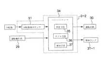
図12は、第3の実施形態に係る監視装置の概略構成を示す機能ブロック図である。
なお、この第3の実施形態に係る監視装置D−2は、脱臭フィルタ5の目詰まりの発生を検出する検出手段として、中間ダクトファンAの電動送風機6(ファンモータ6b)の回転数を検出する回転数検出手段を用いて構成した以外の構成要素においては、前記の第1の実施形態に係る監視装置Dと基本的に同じことから同じ構成要素に同じ符合を付することで重複説明は省略する。<< Configuration of Monitoring Device According to Third Embodiment >>
FIG. 12 is a functional block diagram illustrating a schematic configuration of the monitoring apparatus according to the third embodiment.
The monitoring device D-2 according to the third embodiment detects the number of rotations of the electric blower 6 (
すなわち、監視装置D−2は、図12に示すように、電動送風機6のファンモータ6bの回転数を検出する回転数検出手段である回転数検出センサ51と、この回転数検出センサ51により検出された検出回転数値Nnに基づいて脱臭フィルタ5の目詰まり度合いを判定し、かつ、脱臭フィルタ5が目詰まり状態にあると判定したきには使用者に報知するマイクロコンピュータ34とを備えて構成されている。That is, as shown in FIG. 12, the monitoring device D-2 detects a rotational
マイクロコンピュータ34には、図12に示すように、回転数検出センサ51により検出された検出回転数値Nnと、予め定められている設定回転数値Nとを比較する判定手段35、この判定手段35により電動送風機6の回転数に変化があると判定されたときに、動作を開始して時間を累積(カウント)するタイマ手段36、このタイマ手段36による累積時間TΣnが、予め定められている設定時間Tに達するか、この設定時間Tを越えたときに、脱臭フィルタ5に目詰まりが発生し、脱臭フィルタ5の保守時期であることを、報知ランプ37−1を点灯させることで使用者に報知する報知手段37、これらの各機能などが内蔵されている。As shown in FIG. 12, the
≪回転数検出センサの構成≫
回転数検出センサ51は、光学式センサなどからなり、中間ダクトファンAの電動送風機6が運転中に、該ファンモータ6bの回転数を検出し、その検出した検出回転数値Nnを判定手段35に出力するように構成されている。
つまり、脱臭フィルタ5の目詰まりが進行すると、レンジフードBの排気電動送風機27の吸引力によって送風ダクト1内に送り込まれ、送風ダクト1に接続されている中間ダクトファンAの吸込み口4aから中間ダクトファンA内に流入される臭気成分を含む排気流Gの風量は減少する。
これにより、電動送風機6(排気ファン6c)に対する排気流Gの空気流抵抗(負荷)が減少するに伴い、ファンモータ6bの回転数が大きくなる。このため、ファンモータ6bの回転数を検出することにより、脱臭フィルタ5の目詰まり情報を得ることができる。≪Configuration of rotational speed detection sensor≫
The rotation
That is, when the clogging of the
Thereby, as the air flow resistance (load) of the exhaust flow G to the electric blower 6 (
また、この回転数検出センサ51は、第1の実施形態に詳述した圧力検出センサ33と同じく、所定の時間間隔Δt、例えば、約1〜4秒の間隔をおいて回転数の検出を実行するように構成されている。つまり、マイクロコンピュータ34のメモリ(図示省略)に入力されている制御プログラムによって所定の時間間隔Δtをおいてファンモータ6bの回転数を検出するように設定されている。 The rotation
[作用説明]
つぎに、以上のように構成されている第3の実施形態に係る監視装置D−2による中間ダクトファンAのフィルタ目詰まり監視について説明する。
図13は、第3の実施形態に係る監視装置による中間ダクトファン(脱臭フィルタ)の目詰まり監視動作の一例を示すフローチャートである。ここでは、図3を適宜参照しながら説明する。[Description of operation]
Next, filter clogging monitoring of the intermediate duct fan A by the monitoring device D-2 according to the third embodiment configured as described above will be described.
FIG. 13 is a flowchart illustrating an example of the clogging monitoring operation of the intermediate duct fan (deodorizing filter) by the monitoring device according to the third embodiment. Here, description will be made with reference to FIG. 3 as appropriate.
中間ダクトファンAの運転中、電動送風機6のファンモータ6cの回転数が回転数検出センサ51によって検出され(ステップ52)、検出された検出回転数値Nnは、判定手段35へと出力される。判定手段35に検出回転数値Nnが入力されてくると、判定手段35による検出回転数値Nnと設定回転数値Nとを比較する判定が実行される(ステップ53)。このとき、回転数検出センサ51による検出と判定手段35による判定は、所定の時間間隔(例えば、約1〜4秒の間隔)Δtにて継続的に繰り返し行われる。During the operation of the intermediate duct fan A, the rotational speed of the
判定手段35によって、検出回転数値Nnが設定回転数値Nに達するか、それよりも大きいと判定(YESと判定)されると、タイマ手段36にカウント信号が出力される。タイマ手段36は、判定手段35からカウント信号が入力されてきた時点で、動作を開始し、時間の累積を実行する(ステップ54)。このとき、検出回転数値Nnが設定回転数値Nよりも小さいと判定(NOと判定)されると、ステップ52に戻される。このとき、設定時間Tに達していない累積時間TΣnはリセットされる(ステップ55)。If the determination means 35 determines that the detected rotation value Nn reaches or exceeds the set rotation value N (YES), a count signal is output to the timer means 36. When the count signal is input from the
タイマ手段36による時間の累積が実行され、その累積時間TΣnが設定時間Tに達するか、それを越えると(ステップ56)、タイマ手段36から報知手段37に報知信号が出力される。報知手段37は、報知信号を受けて報知ランプ37−1を点灯させる(ステップ57)。Accumulation of time by the timer means 36 is executed, and when the accumulated timeTΣn reaches or exceeds the set time T (step 56), a notification signal is output from the timer means 36 to the notification means 37. The notification means 37 receives the notification signal and turns on the notification lamp 37-1 (step 57).
このように、第3の実施形態に係る監視装置D−2によれば、図3に示すように、天井裏Cなどの空間に設置されている中間ダクトファンAの臭気フィルタ5に目詰まりが発生すると、回転数検出センサ51による電動送風機6のファンモータ6bの回転数の検出、判定手段35による検出回転数値Nnと設定回転数値Nとの比較判断、そしてタイマ手段36によるノイズの除去によって、的確に、精度良く、脱臭フィルタ5が目詰まりを発生したことを報知手段37(報知ランプ37−1)よって使用者に知らせることができる。Thus, according to the monitoring apparatus D-2 according to the third embodiment, as shown in FIG. 3, the
≪第4の実施形態に係る監視装置の構成≫
図14は、第4の実施形態に係る監視装置の概略構成を示す機能ブロック図である。
なお、この第4の実施形態に係る監視装置D−3は、脱臭フィルタ5の目詰まりの発生を検出する検出手段として、電動送風機6(ファンモータ6b)に流れる消費電力を検出す消費電力検出手段を用いて構成した以外の構成要素においては、前記の第1の実施形態に係る監視装置Dと基本的に同じことから同じ構成要素に同じ符合を付することで重複説明は省略する。<< Configuration of Monitoring Device According to Fourth Embodiment >>
FIG. 14 is a functional block diagram illustrating a schematic configuration of the monitoring apparatus according to the fourth embodiment.
The monitoring device D-3 according to the fourth embodiment detects power consumption flowing in the electric blower 6 (
すなわち、監視装置D−3は、図14に示すように、ファンモータ6bに流れる消費電力を検出する消費電力検出手段である消費電力検出センサ58と、この消費電力検出センサ58により検出された検出消費電力Wnに基づいて脱臭フィルタ5の目詰まり度合いを判定し、かつ、脱臭フィルタ5が目詰まり状態にあると判定したきには使用者に報知するマイクロコンピュータ34とを備えて構成されている。That is, as shown in FIG. 14, the monitoring device D-3 includes a power
マイクロコンピュータ34は、図14に示すように、消費電力検出センサ58により検出された検出消費電力値Wnと、予め定められている設定消費電力値Wとを比較するための判定手段35、この判定手段35により消費電力に変化があると判定されたときに、動作を開始して時間を累積(カウント)するタイマ手段36、このタイマ手段36による累積時間TΣnが、予め定められている設定時間Tに達するか、この設定時間Tを越えたときに、脱臭フィルタ5に目詰まりが発生し、脱臭フィルタ5の保守時期であることを、報知ランプ37−1を点灯させることで使用者に報知する報知手段37、これらの各機能などが内蔵されている。As shown in FIG. 14, the
≪消費電力検出センサの構成≫
消費電力検出センサ58は、電力計などからなり、中間ダクトファンAの電動送風機6が運転中に、ファンモータ6bで消費される消費電力を検出し、その検出した検出消費電力Wnを判定手段35に出力するように構成されている。≪Configuration of power consumption detection sensor≫
また、この消費電力検出センサ58は、第1の実施形態に詳述した圧力検出センサ33と同じく、所定の時間間隔Δt、例えば、約1〜4秒の間隔をおいて風量の検出を実行するように構成されている。つまり、マイクロコンピュータ34のメモリ(図示省略)に入力されている制御プログラムによって所定の時間間隔Δtをおいてファンモータ6bに流れる消費電力を検出するように設定されている。 The power
[作用説明]
つぎに、以上のように構成されている第4の実施形態に係る監視装置D−3による中間ダクトファンAのフィルタ目詰まり監視について説明する。
図15は、第4の実施形態に係る監視装置による中間ダクトファン(脱臭フィルタ)目詰まり監視動作の一例を示すフローチャートである。ここでは、図3を適宜参照しながら説明する。[Description of operation]
Next, the filter clogging monitoring of the intermediate duct fan A by the monitoring device D-3 according to the fourth embodiment configured as described above will be described.
FIG. 15 is a flowchart illustrating an example of an operation for monitoring clogging of an intermediate duct fan (deodorizing filter) by the monitoring device according to the fourth embodiment. Here, description will be made with reference to FIG. 3 as appropriate.
中間ダクトファンAの運転中、電動送風機6のファンモータ6bで消費される消費電力が消費電力検出センサ58によって検出され(ステップ59)、検出された検出消費電力値Wnは、判定手段35へと出力される。判定手段35に検出消費電力値Wnが入力されてくると、判定手段35による検出消費電力値Wnと、予め定められている設定消費電力値Wとを比較する判定が実行される(ステップ60)。このとき、消費電力検出センサ58による検出と判定手段35による判定は、所定の時間間隔(例えば、約1〜4秒の間隔)Δtにて継続的に繰り返し行われる。During the operation of the intermediate duct fan A, the power consumption consumed by the
判定手段35によって、検出消費電力値Wnが設定消費電力値Wに達するか、それよりも小さいと判定(YESと判定)されると、タイマ手段36にカウント信号が出力される。タイマ手段36は、判定手段35からカウント信号が入力されてきた時点で、動作を開始し、時間の累積を実行する(ステップ61)。このとき、検出消費電力値Wnが設定消費電力値Wよりも大きいと判定(NOと判定)されると、ステップ59に戻される。このとき、設定時間Tに達していない累積時間TΣnはリセットされる(ステップ62)。When the determination means 35 determines that the detected power consumption value Wn reaches the set power consumption value W or is smaller (determined as YES), a count signal is output to the timer means 36. When the count signal is input from the determination means 35, the timer means 36 starts operation and accumulates time (step 61). At this time,if it is determined that the detected power consumption value Wn is greater than the set power consumption value W (determined as NO), the process returns to step 59. At this time, the accumulated timeTΣn that has not reached the set time T is reset (step 62).
タイマ手段36による時間の累積が実行され、その累積時間TΣnが設定時間Tに達するか、それを越えると(ステップ63)、タイマ手段36から報知手段37に報知信号が出力される。報知手段37は、報知信号を受けて報知ランプ37−1を点灯させる(ステップ64)。Accumulation of time by the timer means 36 is executed, and when the accumulated timeTΣn reaches or exceeds the set time T (step 63), a notification signal is output from the timer means 36 to the notification means 37. The notification means 37 receives the notification signal and turns on the notification lamp 37-1 (step 64).
このように、第4の実施形態に係る監視装置D−3によれば、図3に示すように、天井裏Cなどに設置されている中間ダクトファンAの運転中に、臭気フィルタ5に目詰まりが発生すると、ファンモータ6bで消費される消費電力の消費電力検出センサ58による検出、判定手段35による検出消費電力値Wnと設定消費電力値Wとの比較判断、そしてタイマ手段36によるノイズの除去によって、的確に、精度良く、脱臭フィルタ5が目詰まりを発生したことを報知手段37(報知ランプ37−1の点灯)にて使用者に知らせることができる。Thus, according to the monitoring apparatus D-3 according to the fourth embodiment, as shown in FIG. 3, the
≪第5の実施形態に係る監視装置の構成≫
図16は、第5の実施形態に係る監視装置の概略構成を示す機能ブロック図である。ここでは、図1および図2を適宜参照しながら説明する。
この第5の実施形態に係る監視装置D−4は、中間ダクトファンBのケース体4内での排気流Gの静圧を検出する検出手段として、前記した第1の実施形態における圧力検出センサ(圧力検出手段)33に変えて、差圧検出手段を用いたものであり、差圧検出手段を用いた以外の構成要素においては、前記の第1の実施形態に係る監視装置Dと基本的に同じことから同じ構成要素に同じ符合を付することで重複説明は省略する。<< Configuration of Monitoring Device According to Fifth Embodiment >>
FIG. 16 is a functional block diagram illustrating a schematic configuration of a monitoring device according to the fifth embodiment. Here, description will be made with reference to FIGS. 1 and 2 as appropriate.
The monitoring device D-4 according to the fifth embodiment is a pressure detection sensor according to the first embodiment described above as detection means for detecting the static pressure of the exhaust flow G in the case body 4 of the intermediate duct fan B. (Pressure detection means) A differential pressure detection means is used instead of the pressure detection means 33. In the constituent elements other than using the differential pressure detection means, the monitoring device D according to the first embodiment is basically the same as the above. The same reference numerals are given to the same components and the duplicated explanation is omitted.
すなわち、監視装置D−4は、図16に示すように、排気流Gの静圧を検出する差圧検出手段としての差圧検出センサ65と、この差圧検出センサ65により検出された検出差圧値Snに基づいて脱臭フィルタ5の目詰まり度合いを判定し、かつ、脱臭フィルタ5が目詰まり状態にあると判定したきには使用者に報知するマイクロコンピュータ34とを備えて構成されている。That is, as shown in FIG. 16, the monitoring device D-4 includes a differential
マイクロコンピュータ34は、図16に示すように、差圧検出センサ65により検出された検出差圧値Snと、予め設定されている設定差圧値Sとを比較するための判定手段35、この判定手段35によりケース体4内における脱臭フィルタ5を挟むその上流側(吸込み口4a側)と下流側(前記した下流側空間15側)との間に生じる静圧の差圧に変化があると判定されたときに、動作を開始して時間を累積(カウント)するタイマ手段36、このタイマ手段36による累積時間TΣnが、予め定められている設定時間Tに達するか、この設定時間Tを越えたときに、脱臭フィルタ5に目詰まりが発生し、脱臭フィルタ5の保守時期であることを、報知ランプ37−1を点灯させることで使用者に報知する報知手段37、これらの各機能などが内蔵されている。The
≪差圧検出センサの構成≫
差圧検出センサ65は、図1および図2に示す中間ダクトファンAのケース体4内における脱臭フィルタ5を挟むその上流側(吸込み口4a側)と下流側(前記した下流側空間15側)との間に生じる静圧の差圧値を検出し、その差圧値を検出差圧値Snとして判定手段35に出力するように構成されている。
この差圧検出センサ65としては、種々の構造形態のものが知られているが、その一例として、例えば、ダイアフラムを内部に備えているセンサ本体を、図1および図2に示すケース体4内における脱臭フィルタ5の上流側(吸込み口4a側)と下流側(下流側空間18側)とにバイパスを介してそれぞれ連通状に接続し、上流側と下流側との静圧の差圧によりダイアフラムが変形することで検出される検出差圧値Snを判断手段35に出力するように構成されている。≪Configuration of differential pressure detection sensor≫
The differential
As the differential
[作用説明]
つぎに、以上のように構成されている第5の実施形態に係る監視装置D−4による中間ダクトファンAのフィルタ目詰まり監視について説明する。
図17は、第5の実施形態に係る監視装置による中間ダクトファン(脱臭フィルタ)の目詰まり監視動作の一例を示すフローチャートである。ここでは、図3を適宜参照しながら説明する。[Description of operation]
Next, filter clogging monitoring of the intermediate duct fan A by the monitoring device D-4 according to the fifth embodiment configured as described above will be described.
FIG. 17 is a flowchart illustrating an example of the clogging monitoring operation of the intermediate duct fan (deodorizing filter) by the monitoring device according to the fifth embodiment. Here, description will be made with reference to FIG. 3 as appropriate.
中間ダクトファンAの運転中、ケース体4内における脱臭フィルタ5の上流側(吸込み口4側)と下流側(下流側空間18側)との間に生じる差圧が差圧検出センサ65により検出差圧値Snとして検出され(ステップ66)、検出された検出差圧値Snは、判定手段35へと出力される。判定手段35に検出差圧値Snが入力されてくると、判定手段35による検出差圧値Snと設定差圧値Sとを比較する判定が実行される(ステップ67)。このとき、差圧検出センサ65による検出と判定手段35による判定は、所定の時間間隔(例えば、約1〜4秒の間隔)Δtにて継続的に繰り返し行われる。
判定手段35によって、検出差圧値Snが設定差圧値Sよりも大きいと判定(YESと判定)されると、タイマ手段36にカウント信号が出力される。タイマ手段36は、判定手段35からカウント信号が入力されてきた時点で、動作を開始し、時間の累積を実行する(ステップ68)。このとき、検出差圧値Snが設定差圧値Sよりも小さい判定(NOと判定)されると、ステップ16に戻される。このとき、設定時間Tに達していない累積時間TΣnはリセットされる(ステップ69)。During the operation of the intermediate duct fan A, a differential
The determining means 35, when the detection pressure value Sn is determined to be greater than the set pressure value S (YES as determination), the count signal is output to the timer means 36. When the count signal is input from the determination means 35, the timer means 36 starts to operate and accumulates time (step 68). At this time,if it is determined that the detected differential pressure value Sn is smaller than the set differential pressure value S (determined as NO), the process returns to step 16. At this time, the accumulated timeTΣn that has not reached the set time T is reset (step 69).
タイマ手段36による時間の累積が実行され、その累積時間TΣnが設定時間Tに達するか、それを越えると(ステップ70)、タイマ手段36から報知手段37に報知信号が出力される。報知手段37は、報知信号を受けて報知ランプ37−1を点灯させる(ステップ71)。Accumulation of time by the timer means 36 is executed, and when the accumulated timeTΣn reaches or exceeds the set time T (step 70), a notification signal is output from the timer means 36 to the notification means 37. The notification means 37 receives the notification signal and turns on the notification lamp 37-1 (step 71).
このように、第5の実施形態に係る監視装置D−4によれば、図3に示すように、天井裏Cなどに設置されている中間ダクトファンAの臭気フィルタ5に目詰まりが発生すると、差圧検出センサ65による脱臭フィルタ5を挟む上流側と下流側との2ヶ所における双方向の排気流Gの静圧によって検出される検出差圧値Sn、判定手段35による検出差圧値Snと設定差圧値Sとの比較判定、そしてタイマ手段36によるノイズの除去によって、的確に、精度良く、脱臭フィルタ5が目詰まりを発生したことを報知ランプ37−1にて使用者に知らせることができる。As described above, according to the monitoring device D-4 according to the fifth embodiment, when the
なお、この第5の実施形態に係る監視装置D−4では、差圧検出センサ65の他の実施形態として、脱臭フィルタ5を挟む上流側(吸込み口4a側)と下流側空間18側との排気流Gの静圧をそれぞれ検出し、その上流側静圧と下流側静圧とから差圧値を算出し、この算出差圧値を検出差圧値Snとして判断手段35に出力するように構成することもできる。In the monitoring device D-4 according to the fifth embodiment, as another embodiment of the differential
≪第6の実施形態に係る監視装置の構成≫
図18は、第6の実施形態に係る監視装置の概略構成を示す機能ブロック図である。ここでは、図1から図4を適宜参照しながら説明する。
この第6の実施形態に係る監視装置D−5では、前記の第1の実施形態に係る監視装置Dと基本的に同じ構成要素においては、同じ符合を付することで重複説明は省略する。<< Configuration of Monitoring Device According to Sixth Embodiment >>
FIG. 18 is a functional block diagram illustrating a schematic configuration of a monitoring apparatus according to the sixth embodiment. Here, description will be made with reference to FIGS. 1 to 4 as appropriate.
In the monitoring device D-5 according to the sixth embodiment, the same components as those of the monitoring device D according to the first embodiment are denoted by the same reference numerals, and redundant description is omitted.
監視装置D−5は、図1および図2に示す中間ダクトファンAの電動送風機6の累積総運転時間TΣnから脱臭フィルタ5の目詰まり保守時期を使用者に知らせるように構成されている。
すなわち、前記の実施形態において詳述したように、図3および図4に示すレンジフードBの排気電動送風機27の運転に同調して運転する中間ダクトファンAの電動送風機6の累積総運転時間TΣnが、例えば、300時間に設定されている設定運転時間Tに達したときに、脱臭フィルタ5の目詰まり保守時期を使用者に知らせるように構成されている。
なお、この第6の実施形態に係る監視装置D−5では、前記の第1の実施形態に係る監視装置Dと基本的に同じ構成要素においては、同じ符合を付することで重複説明は省略する。The monitoring device D-5 is configured to notify the user of the clogged maintenance time of the
That is, as described in detail in the above embodiment, the cumulative total operation time T of the
Note that in the monitoring device D-5 according to the sixth embodiment, the same components as those in the monitoring device D according to the first embodiment are denoted by the same reference numerals, and redundant description is omitted. To do.
監視装置D−5は、図18に示すように、日々の調理のときに繰り返し使用されるレンジフードBの運転に同調して運転される中間ダクトファンAの電動送風機6が運転しているときに、その運転時間Δtを累積し、この運転時間Δtの累積総運転時間TΣnが、設定運転時間Tに達したときに、脱臭フィルタ5の目詰まり保守時期を使用者に報知するマイクロコンピュータ72を備えて構成されている。As shown in FIG. 18, the monitoring device D-5 operates when the
マイクロコンピュータ72には、図18に示すように、中間ダクトファンAの運転時間Δtを累積するタイマ手段73、このタイマ手段73による中間ダクトファンAの累積総運転時間TΣnが、予め定められている設定運転時間Tに達するか、この設定運転時間Tを越えたときに、脱臭フィルタ5の目詰まり保守時期を使用者に報知する報知手段37、これらの各機能などが内蔵されている。
タイマ手段73、報知手段37は中間ダクトファンAの運転中に機能するように設定されている。As shown in FIG. 18, the
The timer means 73 and the notification means 37 are set to function during the operation of the intermediate duct fan A.
≪タイマ手段の構成≫
タイマ手段73は、中間ダクトファンAの累積総運転時間TΣnが、設定運転時間Tに達するか、この設定運転時間Tを越えたときに、報知手段37に報知信号を出力するように構成されている。
そして、このタイマ手段73は、運転操作部29の運転ON操作が成され、レンジフードBの排気電動送風機27の運転に同調して運転する中間ダクトファンAの電動送風機6が運転を開始した時点で、電動送風機6の運転時間Δtの累積(カウント)を開始し、電動送風機6の運転が継続している間において運転時間Δtの累積を続け、運転操作部29の運転OFF操作が成され、電動送風機6の運転が停止された時点で運転時間Δtを終了するように構成されている。≪Configuration of timer means≫
The timer unit 73 is configured to output a notification signal to the
And this timer means 73 is the time when the operation ON operation of the
また、タイマ手段73は、運転時間Δtの累積総運転時間TΣnが、予め定められている設定運転時間Tに達すか、それを越えた時点で、報知手段37に報知信号を出力するように構成されている。
ここで、累積運転時間TΣn−1は、毎回の調理のときに排気電動送風機27の運転に同調して運転される電動送風機6の運転のたびに累積される運転時間Δtの毎回の累算時間であり、累積総運転時間TΣnは、前回までに累算された累積運転時間TΣn−1と、今回の排気電動送風機27の運転により累積されている今回の運転時間Δtとの累算時間である。In addition, the timer means 73 outputs a notification signal to the notification means 37 when the accumulated total operation timeTΣn of the operation time Δt reaches or exceeds a predetermined set operation time T. It is configured.
Here, the cumulative operation time TΣn−1 is an accumulation of the operation time Δt accumulated every time the
なお、電動送風機6の運転中に継続して累積される運転時間Δtは、電動送風機6の運転中において累積運転時間TΣn−1に累算されるようにするも、または、電動送風機6の運転が停止された時点において累積運転時間TΣn−1に累算されるようにするも任意である。The operation time Δt continuously accumulated during the operation of the
また、タイマ手段73は、運転操作部29の運転OFF操作が成され、電動送風機6の運転が停止された時点で運転時間Δtの累積を終了し、この終了時点における今回の運転時間Δtと、前回までの累積運転時間TΣn−1とが累積総運転時間TΣnに累算されて、次回に電動送風機6が運転されて運転時間Δtの累積が開始するまで残されている。
つまり、タイマ手段73は、電動送風機6の累積総運転時間TΣnが、設定運転時間Tに達するか、この設定運転時間Tを越えて、脱臭フィルタ5の目詰まり保守時期が報知手段37によって使用者に知らされ、使用者がレンジフードBの前面に備えられている消灯釦を押すまで、累積運転時間TΣn−1と累積総運転時間TΣnとはマイクロコンピュータ72の図示省略のメモリなどに記録されて残されるように構成されている。Further, the timer means 73 ends the accumulation of the operation time Δt when the operation OFF operation of the
In other words, the timer means 73 uses the notification means 37 when the accumulated total operation timeTΣn of the
≪報知手段の構成≫
報知手段37は、前記の第1の実施形態に係る監視装置Dと同様に構成されている。
つまり、報知手段37は、発光ダイオード,HIDランプなどからなる報知ランプ37−1を備え、タイマ手段73から出力される報知信号を受けたときに、報知ランプ37−1を点灯、または、点滅させることで、脱臭フィルタ5が目詰まり状態の保守時期であることを使用者に報知するように構成されている。
また、報知ランプ37−1は、報知手段37から消灯指令により、または、運転操作部29の各スイッチ類と並設させて、該運転操作部29に備えられる図示省略の消灯釦を使用者が押すなどによって消灯するようになっている。≪Configuration of notification means≫
The
That is, the
In addition, the notification lamp 37-1 is provided with a turn-off button (not shown) provided in the driving
[作用説明]
つぎに、以上のように構成されている第6の実施形態に係る監視装置D−5による中間ダクトファンAのフィルタ目詰まり監視について説明する。
図19は、監視装置による中間ダクトファン(脱臭フィルタ)の目詰まり監視動作の一例を示すフローチャートである。ここでは、図1〜図4を適宜参照しながら説明する。[Description of operation]
Next, filter clogging monitoring of the intermediate duct fan A by the monitoring device D-5 according to the sixth embodiment configured as described above will be described.
FIG. 19 is a flowchart showing an example of the clogging monitoring operation of the intermediate duct fan (deodorizing filter) by the monitoring device. Here, it demonstrates, referring suitably FIGS. 1-4.
調理のときに、図4に示すレンジフードBの前面に備えられている運転操作部29の運転ON操作が成され、レンジフードBの排気電動送風機27を運転させると、排気電動送風機27の運転に同調して、図1および図2に示す中間ダクトファンAの電動送風機6が運転を開始する(ステップ74)。
電動送風機6が運転を開始すると、タイマ手段73の運転時間Δtが累積を開始する(ステップ75)。このとき、前回の電動送風機6の運転時間Δtが累積された状態で残っているときには、電動送風機6が運転を開始した時点で、前回の運転時間Δtはリセットされ、0から新たに今回の運転時間Δtの累積が開始される。
このようにして、日々の調理のときに累積される電動送風機6の運転時間Δtは、累積を開始すると同時に累積運転時間TΣn−1に逐次累算され、なおかつ、累積総運転時間TΣnとして逐次累算される(ステップ76)とともに、累積総運転時間TΣnと設定運転時間Tとの比較が実行される(ステップ77)。When cooking, the operation ON operation of the
When the
In this way, the operation time Δt of the
累積総運転時間TΣnが設定運転時間Tに達するか、この設定運転時間Tを越えると、タイマ手段73から報知手段37に報知信号が出力される。報知手段37は、報知信号を受けて報知ランプ37−1を点灯させる(ステップ81)。このとき、累積総運転時間TΣnが設定運転時間Tに達しておらず、また、電動送風機6の運転が停止されていないとき(ステップ79)には、ステップ76に戻される。一方、電動送風機6の運転が停止された場合には、運転時間Δtの累積が終了し(ステップ80)、運転が停止されるまで累積された今回の運転時間Δtが累算された累積運転時間TΣn−1と累積総運転時間TΣnは、マイクロコンピュータ72の図示省略のメモリなどに記録されて残される(ステップ81)。When the accumulated total operation timeTΣn reaches the set operation time T or exceeds the set operation time T, a notification signal is output from the timer unit 73 to the
報知ランプ37−1が点灯し、使用者に脱臭フィルタ5が目詰まり状態の保守時期であることを知らせ、レンジフードBの前面に備えられている消灯釦が押されると(ステップ82)と、報知ランプ37−1は消灯され(ステップ83)、同時に累積総運転時間TΣnと累積運転時間TΣn−1がリセットされて、0に戻される(ステップ84)。When the notification lamp 37-1 is lit, the user is informed that the
このように、第6の実施形態に係る監視装置D−5によれば、図3に示すように、天井裏Cなどに設置されている中間ダクトファンBの臭気フィルタ5の目詰まり保守時期を、タイマ手段73による電動送風機6の累積総運転時間TΣnと、報知手段37とによって脱臭フィルタ5の目詰まり保守時期を使用者に知らせることができる。Thus, according to the monitoring apparatus D-5 according to the sixth embodiment, as shown in FIG. 3, the maintenance time for clogging the
なお、本発明の実施形態の具体的な構成は、前記した各実施形態に限られるものではなく、請求項1から請求項12に記載の本発明の要旨を逸脱しない範囲で設計変更などがあっても本発明に含まれるものである。
例えば、中間ダクトファンAを、屋内の天井などに設けられている給排気用の吸気口から屋外の排気口3に、天井裏Cなどの空間を通して配管される送風ダクトに設置して使用することができる。
また、中間ダクトファンAのケース体4内に内設させる空気清浄フィルタとして、除塵フィルタ、活性炭フィルタなどを使用、または、除塵フィルタ、活性炭フィルタと、脱臭フィルタ5との組み合わせとすることができる。The specific configuration of the embodiment of the present invention is not limited to each of the above-described embodiments, and there are design changes and the like without departing from the gist of the present invention described in
For example, the intermediate duct fan A is used by being installed in a ventilation duct that is piped through a space such as the ceiling back C from the air intake / exhaust air inlet provided on the indoor ceiling to the
Moreover, as an air purifying filter installed in the case body 4 of the intermediate duct fan A, a dust removing filter, an activated carbon filter, or the like can be used, or a combination of the dust removing filter, the activated carbon filter, and the
また、電動送風機6の排気ファン6cとして、プロペラファンやターボファンなどを使用することができる。この場合、空気清浄フィルタの目詰まり保守時期を監視する監視装置D,D−1,D−4において、それぞれの静圧、風量の変化の特性、そしてファンモータの回転数の変化の特性に合わせて判定手段を構成することで同様な機能を持たせることができる。 Moreover, a propeller fan, a turbo fan, etc. can be used as the
さらに、電動送風機6のファンモータ6bとして直流モータを用いることができる。この場合、第3の実施形態に係る監視装置D−2を備えている中間ダクトファンAにおいて、回転数検出センサ51を用いることなく、ファンモータ6bの回転数を検出することができる。
さらにまた、各監視装置D,D−1,D−2,D−3,D−4,D−5において、報知手段37により空気清浄フィルタの目詰まり保守時期を使用者に報知する報知手段37を、報知ランプのほかに、ブザー、音声などを挙げることができる。Furthermore, a DC motor can be used as the
Furthermore, in each of the monitoring devices D, D-1, D-2, D-3, D-4, and D-5, an informing
また、前記した各監視装置D,D−1,D−2,D−3,D−4,においては、累積時間のカウント(累積)を判定手段からのカウント信号の継続的な繰り返しにより行うようにしたが、最初に判定手段35が異常(YES)と判断したときに、タイマ手段36にカウント開始信号を出力し、このカウント開始信号によりタイマ手段36は時間のカウントを自動で継続し、その後、判定手段35が正常(NO)と判断したときはタイマ手段36にカウント停止信号を出力することで、タイマ手段36を停止およびリセットするように構成することもできる。 In each of the monitoring devices D, D-1, D-2, D-3, and D-4, the accumulated time is counted (accumulated) by continuously repeating the count signal from the determination means. However, when the determination means 35 first determines that there is an abnormality (YES), it outputs a count start signal to the timer means 36, and the timer means 36 automatically continues to count the time by this count start signal. When the
また、監視装置D−5による空気清浄フィルタの目詰まり監視、つまり、タイマ手段73による電動送風機6の運転時間(累積総運転時間)によって空気清浄フィルタの目詰まりを監視する構成の前記した第6の実施形態においては、その他の実施形態として、電動送風機6の運転時間を、電動送風機6の運転中に継続的に累積し、その運転時間が設定運転時間に達するか、設定運転時間を越えたときに、報知手段37によって使用者に目詰まり保守時期を報知するように構成することができる。つまり、この場合には、監視中の電動送風機6の運転時間が、例えば、前記した第6の実施形態のように、300時間に設定されている設定運転時間に達するか、設定運転時間を越えたときに、脱臭フィルタ5の目詰まり保守時期を使用者に知らせるように構成されている。 Further, the monitoring device D-5 monitors the clogging of the air purification filter, that is, the above-described sixth configuration is configured to monitor the clogging of the air purification filter by the operation time (cumulative total operation time) of the
A 中間ダクトファン
B レンジフード
C 天井裏
D,D−1,D−2,D−3,D−4,D−5 監視装置
1 送風ダクト
2 接続口具
3 排気口
4 ケース体
4a 吸込み口
4b,4b−1〜4b−3 吐出し口
5 脱臭フィルタ(空気清浄フィルタ)
6 電動送風機
6a ファンケーシング
6b ファンモータ
6c 排気ファン
7 閉鎖蓋
13 排気口(排気電動送風機)
23 分配部材
24 分散部材
27 排気電動送風機
29 運転操作部
30 運転回路
33 圧力検出センサ(検出手段)
34,72 マイクロコンピュータ
35 判定手段
36,73 タイマ手段
37 報知手段
44 風量検出センサ(検出手段)
51 回転数検出センサ(検出手段)
58 消費電力検出センサ(検出手段)
G 排気流(空気流)A Intermediate duct fan B Range hood C Ceiling back D, D-1, D-2, D-3, D-4, D-5
6
DESCRIPTION OF
34, 72
51 Rotational speed detection sensor (detection means)
58 Power consumption detection sensor (detection means)
G exhaust flow (air flow)
Claims (11)
Translated fromJapanese前記送風ダクトに接続される空気流の吸込み口と吐出し口とを有するケース体内に、前記空気流中に含まれている汚染物質を除去する空気清浄フィルタと、前記空気流の吸込み力を発する電動送風機と、を内設し、
前記電動送風機が、前記送風ダクトを通して調理中に発生する排気流を屋外に排気するレンジフードの排気電動送風機の運転強弱の切り換え運転に同調するように構成されていることを特徴とする中間ダクトファン。An intermediate duct fan installed in the middle of an air duct that is piped indoors to outdoors,
An air purifying filter for removing contaminants contained in the air flow and a suction force of the air flow are generated in a case body having an air flow suction port and a discharge port connected to the air duct. An electric blower,
An intermediate duct fan characterized in that theelectric blower is configured tosynchronize with the operation of switching the strength of the exhaust electric blower of the range hood that exhausts the exhaust flow generated during cooking through the blow duct to the outside. .
前記吐出し口は、閉鎖蓋によって密閉自在に形成されていることを特徴とする請求項1から請求項4のいずれか1項に記載の中間ダクトファン。The case body includes the discharge port to which the exhaust port of the electric blower and the blower duct are connected in a plurality of directions.
The intermediate duct fan according to any one of claims 1 to 4, wherein the discharge port is formed so as to be freely sealed by a closing lid.
前記目詰まり監視装置は、前記ケース体内における前記空気流の静圧または風量、あるいは、前記電動送風機の回転数または消費電力を検出する検出手段と、
この検出手段によって検出された前記空気流の検出静圧値と設定静圧値または前記空気流の検出風量値と設定風量値、あるいは、前記電動送風機の検出回転数値と設定回転数値または前記電動送風機の検出消費電力値と設定消費電力値とを比較する判定手段と、
この判定手段によって前記空気流の静圧または風量、あるいは、前記電動送風機の回転数または消費電力に変化があると判定されたときに、前記空気清浄フィルタの目詰まりによる保守時期を報知する報知手段と、を備えて構成されていること特徴とする請求項1から請求項8のいずれか1項に記載の中間ダクトファン。A clogging monitoring device for the air purifying filter;
The clogging monitoring device comprises a detecting means for detecting a static pressure or an air volume of the air flow in the case body, or a rotational speed or power consumption of the electric blower,
The detected static pressure value and set static pressure value of the air flow or the detected air volume value and set air volume value of the air flow detected by the detecting means, or the detected rotation value and set rotation value of the electric blower, or the electric blower Determining means for comparing the detected power consumption value and the set power consumption value;
Notification means for notifying the maintenance time due to clogging of the air cleaning filter when it is determined by the determination means that there is a change in the static pressure or air volume of the air flow or the rotational speed or power consumption of the electric blower. The intermediate duct fan according to any one of claims 1 to 8, wherein the intermediate duct fan is provided.
前記目詰まり監視装置は、前記電動送風機の運転時間を累積するタイマ手段と、
このタイマ手段により累積された前記運転時間が、設定運転時間に達したときに、前記空気清浄フィルタの目詰まり保守時期を報知する報知手段と、を備えて構成されていることを特徴とする請求項1から請求項8のいずれか1項に記載の中間ダクトファン。A clogging monitoring device for the air purifying filter;
The clogging monitoring device includes timer means for accumulating the operation time of the electric blower,
An informing means for informing the clogged maintenance time of the air purifying filter when the operation time accumulated by the timer means reaches a set operation time. The intermediate duct fan according to any one of claims 1 to 8.
前記電動送風機の運転強弱の切り換え運転によって変化する前記ケース体内における前記排気流の静圧または風量、あるいは、前記電動送風機の回転数または消費電力に応じて、前記目詰まり監視装置の前記判定手段が、前記検出手段によって検出された前記排気流の検出静圧値と前記運転強弱の切り換え運転時における設定静圧値または前記排気流の検出風量値と前記運転強弱の切り換え運転時における設定風量値、あるいは、前記電動送風機の検出回転数値と前記運転強弱の切り換え運転時における設定回転数または前記電動送風機の検出消費電力値と前記運転強弱の切り換え運転時における設定消費電力値とを比較し、前記空気清浄フィルタの目詰まりによる保守時期を判定するように構成されていること特徴とする中間ダクトファン。The intermediate duct fan according to claim 9,
Thedetermination means of the clogging monitoring device according to the static pressure or the air volume of the exhaust flow in the case body, which changes by the switching operation of the electric fan, or the rotational speed or power consumption of the electric fan. , The detected static pressure value of the exhaust flow detected by the detection means and the set static pressure value during the switching operation of the operating strength or the set air volume value during the switching operation of the detected flow amount value of the exhaust flow and the operating strength, Alternatively, the detected rotational value of the electric blower and the set rotational speed at the time of switching operation or the detected power consumption value of the electric blower and the set power consumption value at the time of switching operation strength are compared, and the air intermediate duct fan, characterized by being configured todetermine the maintenance timing of clogging of the cleaning filter
Priority Applications (1)
| Application Number | Priority Date | Filing Date | Title |
|---|---|---|---|
| JP2008106574AJP5250296B2 (en) | 2008-04-16 | 2008-04-16 | Intermediate duct fan |
Applications Claiming Priority (1)
| Application Number | Priority Date | Filing Date | Title |
|---|---|---|---|
| JP2008106574AJP5250296B2 (en) | 2008-04-16 | 2008-04-16 | Intermediate duct fan |
Related Child Applications (1)
| Application Number | Title | Priority Date | Filing Date |
|---|---|---|---|
| JP2012257991ADivisionJP2013061147A (en) | 2012-11-26 | 2012-11-26 | Intermediate duct fan |
Publications (2)
| Publication Number | Publication Date |
|---|---|
| JP2009257663A JP2009257663A (en) | 2009-11-05 |
| JP5250296B2true JP5250296B2 (en) | 2013-07-31 |
Family
ID=41385312
Family Applications (1)
| Application Number | Title | Priority Date | Filing Date |
|---|---|---|---|
| JP2008106574AActiveJP5250296B2 (en) | 2008-04-16 | 2008-04-16 | Intermediate duct fan |
Country Status (1)
| Country | Link |
|---|---|
| JP (1) | JP5250296B2 (en) |
Cited By (7)
| Publication number | Priority date | Publication date | Assignee | Title |
|---|---|---|---|---|
| US8874467B2 (en) | 2011-11-23 | 2014-10-28 | Outerwall Inc | Mobile commerce platforms and associated systems and methods for converting consumer coins, cash, and/or other forms of value for use with same |
| US8967361B2 (en) | 2013-02-27 | 2015-03-03 | Outerwall Inc. | Coin counting and sorting machines |
| US9022841B2 (en) | 2013-05-08 | 2015-05-05 | Outerwall Inc. | Coin counting and/or sorting machines and associated systems and methods |
| US9129294B2 (en) | 2012-02-06 | 2015-09-08 | Outerwall Inc. | Coin counting machines having coupon capabilities, loyalty program capabilities, advertising capabilities, and the like |
| US9594982B2 (en) | 2012-06-05 | 2017-03-14 | Coinstar, Llc | Optical coin discrimination systems and methods for use with consumer-operated kiosks and the like |
| US10346819B2 (en) | 2015-11-19 | 2019-07-09 | Coinstar Asset Holdings, Llc | Mobile device applications, other applications and associated kiosk-based systems and methods for facilitating coin saving |
| US10600069B2 (en) | 2010-11-01 | 2020-03-24 | Cardpool, Inc. | Gift card exchange kiosks and associated methods of use |
Families Citing this family (2)
| Publication number | Priority date | Publication date | Assignee | Title |
|---|---|---|---|---|
| JP6804230B2 (en)* | 2016-08-04 | 2020-12-23 | 株式会社ハーマン | Range food |
| KR200490864Y1 (en)* | 2019-06-14 | 2020-01-14 | 주식회사 엠이씨인터네셔날 | a suppiy apparatus for dust removal and purification air of laundrette |
Family Cites Families (7)
| Publication number | Priority date | Publication date | Assignee | Title |
|---|---|---|---|---|
| JPH04354510A (en)* | 1991-05-31 | 1992-12-08 | Mitsubishi Electric Corp | Oven hood fan |
| JPH0989332A (en)* | 1995-09-22 | 1997-04-04 | Techno Quest:Kk | Ventilation device |
| JP2001336796A (en)* | 2000-05-29 | 2001-12-07 | Takenaka Komuten Co Ltd | Ventilation equipment |
| JP2002039582A (en)* | 2000-07-27 | 2002-02-06 | Tokyu Constr Co Ltd | Indoor ventilation volume control device and indoor ventilation volume control method |
| JP4779554B2 (en)* | 2005-10-07 | 2011-09-28 | パナソニック株式会社 | Duct fan |
| JP4867271B2 (en)* | 2005-10-07 | 2012-02-01 | パナソニック株式会社 | Duct fan |
| JP4844303B2 (en)* | 2006-09-05 | 2011-12-28 | パナソニック株式会社 | Range hood blower |
- 2008
- 2008-04-16JPJP2008106574Apatent/JP5250296B2/enactiveActive
Cited By (9)
| Publication number | Priority date | Publication date | Assignee | Title |
|---|---|---|---|---|
| US10600069B2 (en) | 2010-11-01 | 2020-03-24 | Cardpool, Inc. | Gift card exchange kiosks and associated methods of use |
| US8874467B2 (en) | 2011-11-23 | 2014-10-28 | Outerwall Inc | Mobile commerce platforms and associated systems and methods for converting consumer coins, cash, and/or other forms of value for use with same |
| US11100744B2 (en) | 2011-11-23 | 2021-08-24 | Coinstar Asset Holdings, Llc | Mobile commerce platforms and associated systems and methods for converting consumer coins, cash, and/or other forms of value for use with same |
| US9129294B2 (en) | 2012-02-06 | 2015-09-08 | Outerwall Inc. | Coin counting machines having coupon capabilities, loyalty program capabilities, advertising capabilities, and the like |
| US9594982B2 (en) | 2012-06-05 | 2017-03-14 | Coinstar, Llc | Optical coin discrimination systems and methods for use with consumer-operated kiosks and the like |
| US8967361B2 (en) | 2013-02-27 | 2015-03-03 | Outerwall Inc. | Coin counting and sorting machines |
| US9022841B2 (en) | 2013-05-08 | 2015-05-05 | Outerwall Inc. | Coin counting and/or sorting machines and associated systems and methods |
| US9183687B2 (en) | 2013-05-08 | 2015-11-10 | Outerwall Inc. | Coin counting and/or sorting machines and associated systems and methods |
| US10346819B2 (en) | 2015-11-19 | 2019-07-09 | Coinstar Asset Holdings, Llc | Mobile device applications, other applications and associated kiosk-based systems and methods for facilitating coin saving |
Also Published As
| Publication number | Publication date |
|---|---|
| JP2009257663A (en) | 2009-11-05 |
Similar Documents
| Publication | Publication Date | Title |
|---|---|---|
| JP5250296B2 (en) | Intermediate duct fan | |
| JP2013061147A (en) | Intermediate duct fan | |
| JP2009228992A (en) | Filter clogging monitoring device | |
| KR101996058B1 (en) | Artificial intelligence Air conditioner and control method thereof | |
| US6344074B1 (en) | Ventless air scrubber assembly with multi-stage filters and hood enclosure with great entrapment units | |
| JP2011247503A (en) | Air cleaning unit device for range hood | |
| CN204329185U (en) | Vehicular air purifier | |
| CN113898984A (en) | Range hood, control method thereof and computer-readable storage medium | |
| KR101808120B1 (en) | air purification system that allows individual room control | |
| WO2006137650A1 (en) | Indoor floating dust collecting apparatus using convection flow | |
| KR102641694B1 (en) | Air cleaner for kitchen and air cleaning system having the same | |
| JP2007083106A (en) | Air filter exchange time determination method of fan filter unit, and fan filter unit | |
| JP4374965B2 (en) | Ventilation device | |
| JP6229138B2 (en) | Range food | |
| WO2011074250A1 (en) | Oily smoke purifying device | |
| CN215863620U (en) | Double-ring type efficient oil fume purifier | |
| CN114076333B (en) | Range hood, control method thereof and computer readable storage medium | |
| KR101975707B1 (en) | Household fine dust removal system | |
| JP2000146303A (en) | Hot air heater with air purifier | |
| CN216203830U (en) | Laminar flow air supply ceiling | |
| JP2006336957A (en) | Air cleaner | |
| JP2007196183A (en) | Air cleaner | |
| CN105240893A (en) | Novel kitchen lampblack purification device | |
| CN215259978U (en) | Multifunctional kitchen ventilation equipment | |
| JP5493809B2 (en) | Oil smoke purification device |
Legal Events
| Date | Code | Title | Description |
|---|---|---|---|
| A621 | Written request for application examination | Free format text:JAPANESE INTERMEDIATE CODE: A621 Effective date:20110413 | |
| A977 | Report on retrieval | Free format text:JAPANESE INTERMEDIATE CODE: A971007 Effective date:20120824 | |
| A131 | Notification of reasons for refusal | Free format text:JAPANESE INTERMEDIATE CODE: A131 Effective date:20121002 | |
| A521 | Request for written amendment filed | Free format text:JAPANESE INTERMEDIATE CODE: A523 Effective date:20121126 | |
| TRDD | Decision of grant or rejection written | ||
| A01 | Written decision to grant a patent or to grant a registration (utility model) | Free format text:JAPANESE INTERMEDIATE CODE: A01 Effective date:20130409 | |
| A61 | First payment of annual fees (during grant procedure) | Free format text:JAPANESE INTERMEDIATE CODE: A61 Effective date:20130415 | |
| R150 | Certificate of patent or registration of utility model | Ref document number:5250296 Country of ref document:JP Free format text:JAPANESE INTERMEDIATE CODE: R150 Free format text:JAPANESE INTERMEDIATE CODE: R150 | |
| FPAY | Renewal fee payment (event date is renewal date of database) | Free format text:PAYMENT UNTIL: 20160419 Year of fee payment:3 | |
| R250 | Receipt of annual fees | Free format text:JAPANESE INTERMEDIATE CODE: R250 | |
| R250 | Receipt of annual fees | Free format text:JAPANESE INTERMEDIATE CODE: R250 | |
| R250 | Receipt of annual fees | Free format text:JAPANESE INTERMEDIATE CODE: R250 | |
| R250 | Receipt of annual fees | Free format text:JAPANESE INTERMEDIATE CODE: R250 | |
| R250 | Receipt of annual fees | Free format text:JAPANESE INTERMEDIATE CODE: R250 | |
| R250 | Receipt of annual fees | Free format text:JAPANESE INTERMEDIATE CODE: R250 | |
| R250 | Receipt of annual fees | Free format text:JAPANESE INTERMEDIATE CODE: R250 | |
| R250 | Receipt of annual fees | Free format text:JAPANESE INTERMEDIATE CODE: R250 |