JP5248255B2 - Drive unit - Google Patents
Drive unitDownload PDFInfo
- Publication number
- JP5248255B2 JP5248255B2JP2008253065AJP2008253065AJP5248255B2JP 5248255 B2JP5248255 B2JP 5248255B2JP 2008253065 AJP2008253065 AJP 2008253065AJP 2008253065 AJP2008253065 AJP 2008253065AJP 5248255 B2JP5248255 B2JP 5248255B2
- Authority
- JP
- Japan
- Prior art keywords
- axle case
- brake drum
- drive
- wheel
- fixed
- Prior art date
- Legal status (The legal status is an assumption and is not a legal conclusion. Google has not performed a legal analysis and makes no representation as to the accuracy of the status listed.)
- Active
Links
- 230000002093peripheral effectEffects0.000claimsdescription11
- 230000005540biological transmissionEffects0.000claimsdescription10
- 239000000463materialSubstances0.000claimsdescription8
- 239000010687lubricating oilSubstances0.000claimsdescription3
- 238000010248power generationMethods0.000description3
- 238000002485combustion reactionMethods0.000description2
- 229910001060Gray ironInorganic materials0.000description1
- 238000000034methodMethods0.000description1
- 239000003566sealing materialSubstances0.000description1
- XLYOFNOQVPJJNP-UHFFFAOYSA-NwaterSubstancesOXLYOFNOQVPJJNP-UHFFFAOYSA-N0.000description1
Images


Classifications
- Y—GENERAL TAGGING OF NEW TECHNOLOGICAL DEVELOPMENTS; GENERAL TAGGING OF CROSS-SECTIONAL TECHNOLOGIES SPANNING OVER SEVERAL SECTIONS OF THE IPC; TECHNICAL SUBJECTS COVERED BY FORMER USPC CROSS-REFERENCE ART COLLECTIONS [XRACs] AND DIGESTS
- Y02—TECHNOLOGIES OR APPLICATIONS FOR MITIGATION OR ADAPTATION AGAINST CLIMATE CHANGE
- Y02T—CLIMATE CHANGE MITIGATION TECHNOLOGIES RELATED TO TRANSPORTATION
- Y02T10/00—Road transport of goods or passengers
- Y02T10/60—Other road transportation technologies with climate change mitigation effect
- Y02T10/62—Hybrid vehicles
Landscapes
- Arrangement Or Mounting Of Propulsion Units For Vehicles (AREA)
- Electric Propulsion And Braking For Vehicles (AREA)
- Hybrid Electric Vehicles (AREA)
Description
Translated fromJapanese本発明は、大型トラックなどの車両の車輪を回転させる駆動軸が収納されたアクスルケースなどからなる駆動ユニットに関する。 The present invention relates to a drive unit including an axle case in which a drive shaft that rotates a wheel of a vehicle such as a large truck is housed.
発電専用のエンジン(内燃機関)と、このエンジンが発電した電力を蓄電する蓄電体(二次電池など)とを搭載し、蓄電体に蓄電された電力によってモータを駆動させて車輪を回転させることにより走行するシリアルハイブリッド車が知られている。このシリアルハイブリッド車には、駆動軸の長手方向両端部に連結された車輪ごとに専用の駆動モータが備えられているものもある。これらの駆動モータはホイール内に配置されており、いわゆるホイールインモータと呼ばれている(例えば、特許文献1参照。)。 Equipped with a power generation engine (internal combustion engine) and a power storage unit (such as a secondary battery) that stores the power generated by the engine, and drives the motor with the power stored in the power storage unit to rotate the wheels. A serial hybrid vehicle that travels in accordance with is known. Some serial hybrid vehicles are provided with a dedicated drive motor for each wheel connected to both longitudinal ends of the drive shaft. These drive motors are disposed in the wheel and are called so-called wheel-in motors (see, for example, Patent Document 1).
一般に乗用車や小型トラックのような比較的軽量の車両では、各車輪当たり(一輪当り)の駆動力は小さく、外径がホイールのリム径以下であって、長さが車輪の幅程度の小型の駆動モータを使用しても車輪を十分に駆動できるので、上記のホイールインモータのようなレイアウトが可能である。これに対し、大型トラックの駆動輪はタイヤ及びホイールを1つのハブに2個取付ける構造であり、ホイールのサイズに比較するとより大きな駆動力が必要とされる。このため、大型トラックをシリアルハイブリッド車にする場合、車輪を駆動させる駆動モータの外径をホイールのリム径よりも大きくするか、駆動モータの長さを車輪の幅よりも大きくする必要がある。従って、大型トラックでは、上記したホイールインモータのようなレイアウトは採用できず、より大型の駆動モータをエンジンの後方に配置しておき、プロペラシャフトや差動ギヤ、アクスルシャフト等を介して車輪を駆動するタイプが一般的である。このようなタイプの場合、駆動系はエンジン車のそれとほぼ同じ構成となる。
上述したように、大型トラックにシリアルハイブリッド方式を採用する構造では、乗用車のような小型車両に採用されるホイールインモータを利用できないので、差動ギヤやアクスルシャフトを無くした構造にはできない。このため、駆動軸などから構成される駆動ユニットを簡易な構造にはできない。 As described above, the structure employing the serial hybrid system for large trucks cannot use a wheel-in motor employed in a small vehicle such as a passenger car, and therefore cannot have a structure without a differential gear or an axle shaft. For this reason, the drive unit comprised from a drive shaft etc. cannot be made into a simple structure.
本発明は、上記事情に鑑み、シリアルハイブリッド方式を大型トラックに採用しても簡易な構造にできる駆動ユニットを提供することを目的とする。 In view of the above circumstances, an object of the present invention is to provide a drive unit that can have a simple structure even when a serial hybrid system is employed in a large truck.
上記目的を達成するための本発明の駆動ユニットは、車輪を回転させる駆動軸が収納されたアクスルケースと、アクスルケースの長手方向両端部に回転自在に装着され、車輪と共に回転するブレーキドラムと、電力が蓄電される蓄電体と、アクスルケースの外周面のうちブレーキドラムの近傍に配置され、蓄電体に蓄電された電力によって駆動する駆動モータと、駆動モータの駆動力をブレーキドラムに伝達する動力伝達部材とを備え、動力伝達部材は、駆動モータの回転軸に固定されたピニオンギアと、ブレーキドラムの外周面に固定され、ピニオンギアに噛み合うリングギアとからなり、ピニオンギア及びリングギアを水密に覆うギアカバーを備え、ギアカバーは、車輪を制動するブレーキを取り付けるためのブレーキ取付用ブラケットに固定されたブラケットを介してアクスルケースに固定された、ことを特徴とする駆動ユニットである。The drive unit of the present invention for achieving the above object includes an axle case in which a drive shaft that rotates a wheel is housed, a brake drum that is rotatablymounted at both longitudinal ends of the axle case, and rotates together with the wheel, A power storage unit that stores power, a drive motor that is disposed near the brake drum on the outer peripheral surface of the axle case, and that is driven by the power stored in the power storage unit, and power that transmits the driving force of the drive motor to the brake drume Bei the transmissionmember, the power transmission member includes a pinion gear fixed to the rotating shaft of the drive motor is fixed to the outer peripheral surface of the brake drum consists of a ring gear meshing with the pinion gear, the pinion gear and the ring gear It has a gear cover that covers water tightly, and the gear cover is a brake mounting bracket for mounting a brake that brakes the wheel. Fixed to the axle case through a fixed bracket, adrive unit, characterized in that.
また、本発明の駆動ユニットは、車輪を回転させる駆動軸が収納されたアクスルケースと、アクスルケースの長手方向両端部に回転自在に装着され、車輪と共に回転するブレーキドラムと、電力が蓄電される蓄電体と、アクスルケースの外周面のうちブレーキドラムの近傍に配置され、蓄電体に蓄電された電力によって駆動する駆動モータと、駆動モータの駆動力をブレーキドラムに伝達する動力伝達部材とを備え、動力伝達部材は、駆動モータの回転軸に固定されたピニオンギアと、ブレーキドラムの外周面に固定され、ピニオンギアに噛み合うリングギアとからなり、ピニオンギア及びリングギアを水密に覆うギアカバーを備え、ギアカバーは、車輪を制動するブレーキを取り付けるためのブレーキ取付用ブラケットと一体的に形成されたブラケットを介してアクスルケースに固定された、ことを特徴とする駆動ユニットである。Further, the drive unit of the present invention stores an axle case in which a drive shaft that rotates a wheel is housed, a brake drum that is rotatably attached to both longitudinal ends of the axle case, and rotates together with the wheel, and electric power is stored. A power storage unit, a drive motor that is disposed near the brake drum on the outer peripheral surface of the axle case and that is driven by the power stored in the power storage unit, and a power transmission member that transmits the driving force of the drive motor to the brake drum The power transmission member is composed of a pinion gear fixed to the rotating shaft of the drive motor and a ring gear fixed to the outer peripheral surface of the brake drum and meshing with the pinion gear. The gear cover is formed integrally with a brake mounting bracket for mounting a brake for braking the wheel. Fixed to the axle case through a bracket, a drive unit, characterized in that.
前記ギアカバーの内部に、潤滑油が収容されていてもよい。Lubricating oil may be accommodated inside the gear cover.
前記リングギアが、ブレーキドラムの材料とは異なる材料で構成されると共に、ブレーキドラムにスプラインを介して取り付けられていてもよい。The ring gear may be made of a material different from the material of the brake drum and may be attached to the brake drum via a spline.
前記駆動モータが、アクスルケースを挟んだ両側に一対配置されていてもよい。A pair of the drive motors may be arranged on both sides of the axle case.
前記駆動モータが、モータ取付用ブラケットとギアカバーを介してアクスルケースに固定されていてもよい。The drive motor may be fixed to the axle case via a motor mounting bracket and a gear cover.
本発明によれば、アクスルケースの外周面のうちブレーキドラムの近傍に駆動モータが配置されており、この駆動モータの駆動力を動力伝達部材によってブレーキドラムに伝達して車輪が回転する。従って、プロペラシャフトや差動ギアが不要であり、従来のホイールインモータタイプと同等に簡単な構造の駆動ユニットを大型トラックに採用できることとなる。 According to the present invention, the drive motor is disposed in the vicinity of the brake drum on the outer peripheral surface of the axle case, and the driving force of the drive motor is transmitted to the brake drum by the power transmission member to rotate the wheel. Therefore, a propeller shaft and a differential gear are not required, and a drive unit having a structure as simple as that of a conventional wheel-in motor type can be adopted for a large truck.
本発明は、タイヤ及びホイールを1つのハブに2個取付けた構造の大型トラックに実現された。 The present invention has been realized in a large truck having a structure in which two tires and wheels are attached to one hub.
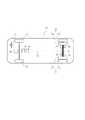
図1を参照して、本願発明の駆動ユニットが採用された大型トラックの概略構造を説明する。 With reference to FIG. 1, a schematic structure of a large truck in which the drive unit of the present invention is adopted will be described.
図1は、大型トラックの概略構造を示す底面図である。 FIG. 1 is a bottom view showing a schematic structure of a large truck.
大型トラック10は、2つの前輪(タイヤ)12と、1つのハブに2つずつ(14a,14bと、15a,15b)装着された後輪14,15を備えている。後輪14と後輪15は、アクスルケース34に収容されたドライブシャフト32(図2参照)に連結されている。運転席17の下方には、発電専用のエンジン(内燃機関)16が配置されている。このエンジン16は発電機19を駆動するだけであり、ここで得られた電力は、二次電池などの蓄電体(充電体)18に蓄電されて(充電されて)、導電ケーブル(導電線)20を通って駆動モータ38,39に供給される。なお、エンジン16と蓄電体18の間には、発電機19が配置されている。上記の駆動モータ38,39の配置について図2から図4までを参照して説明する。 The
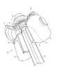
図2は、駆動モータを備えた駆動ユニットを内側(車内側)から示す斜視図であり、一部を破断して示している。図3は、駆動モータを備えた駆動ユニットを外側(車外側)から示す斜視図であり、一部を破断して示している。図4は、駆動ユニットのうち駆動モータ近傍を示す一部断面図である。 FIG. 2 is a perspective view showing a drive unit including a drive motor from the inside (inside the vehicle), and a part thereof is broken away. FIG. 3 is a perspective view showing a drive unit including a drive motor from the outside (vehicle outside), and a part thereof is broken away. FIG. 4 is a partial cross-sectional view showing the vicinity of the drive motor in the drive unit.
駆動ユニット30は、後輪14,15が固定されたドライブシャフト32が収納されたアクスルケース34を備えている。アクスルケース34の長手方向両端部には、後輪14,15と共に回転するブレーキドラム36が回転自在に固定されている。アクスルケース34の外周面のうちブレーキドラム36の近傍には、蓄電体18に蓄電された電力によって駆動する駆動モータ38,39が配置されている。駆動モータ38,39は、アクスルケース34を挟んだ両側に配置された一対のものであり、ブレーキドラム36よりも内側に位置している。駆動モータ38,39は、アクスルケース34にL字状のブラケット40及びギヤカバー42を介して固定されている。なお、ブレーキがエア駆動である場合はブレーキ駆動エアチャンバーの前後反対側に駆動モータ38(又は39)を1個配置すればよく、ブレーキが油圧駆動である場合には駆動モータ38,39をアクスルケース34の車両前後方向に各1個、合計2個配置してもよい。 The
駆動モータ38,39の回転軸38a,39aはアクスルケース34に平行に車外に向けて延びており、これらの回転軸38a,39aにはそれぞれピニオンギア38b,39bが固定されている。また、ブレーキドラム36の外周面には、ピニオンギア38b,39bに噛み合うリングギア36bが固定されている。従って、駆動モータ38,39の駆動力(回転力)は、ピニオンギア38b,39bとリングギア36bによってブレーキドラム36に伝達され、これにより、後輪14,15が回転する。なお、駆動モータ38,39の駆動力をブレーキドラム36に無端ベルトで伝達してもよい。また、駆動モータ38,39の駆動力を所定の減速比でブレーキドラム36に伝達するために、ピニオンギア38b,39bとリングギア36bは歯数が異なるが同一モジュールのものであってもよい。 The
上記したピニオンギア38b,39b及びリングギア36bは、内部に空間が形成された円板状のギアカバー42によって水密に覆われている。このギアカバー42の内部に潤滑油などを収容しておくことにより、ピニオンギア38b,39b及びリングギア36bを円滑に回転させて耐久性を高めることができる。ギアカバー42は、後輪14,15を制動するブレーキ(図示せず)を取り付けるためのブレーキ取付用ブラケット44に取り付けられている。なお、ギアカバー42の一部をシール材で構成してもよい。このシール材やリングギア36bをブレーキドラム36と一体に構成してもよいが、制動に伴う摩擦熱の影響を回避するためと、シール材やリングギア36bの耐久性を確保するために、ブレーキドラム36の一般的な材料であるねずみ鋳鉄とは異なる材料で構成し、ブレーキドラム36本体とはスプライン等のトルク伝達能力の高い構造で連結してもよい。 The above-described
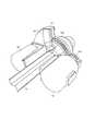
図5と図6を参照してギアカバーの取り付け方法の他の例を説明する。 Another example of the gear cover attaching method will be described with reference to FIGS.
図5は、アクスルケースにブラケットを介して固定されたギアカバーを示す斜視図であり、一部を破断して示している。図6は、ブレーキ取付用ブラケットに一体的に形成されたブラケットを介して固定されたギアカバーを示す斜視図であり、一部を破断して示している。これらの図では、図2と図3に示す構成要素と同じ構成要素には同じ符号が付されている。 FIG. 5 is a perspective view showing a gear cover fixed to the axle case via a bracket, with a part broken away. FIG. 6 is a perspective view showing a gear cover fixed via a bracket integrally formed with the brake mounting bracket, and a part thereof is broken away. In these drawings, the same components as those shown in FIGS. 2 and 3 are denoted by the same reference numerals.
図5に示すように、ギアカバー42は、後輪14,15を制動するブレーキを取り付けるためのブレーキ取付用ブラケット44に固定されたブラケット46を介してアクスルケース34に固定されている。図5に示す構造に代えて、図6に示すように、後輪14,15を制動するブレーキを取り付けるためのブレーキ取付用ブラケット44に一体的にブラケット48を形成しておき、このブラケット48を介してギアカバー42をアクスルケース34に固定してもよい。 As shown in FIG. 5, the
上述したように、アクスルケース34に駆動モータ38,39を固定して後輪14,15を駆動するように構成したのでプロペラシャフトや差動ギアが不要であり、従来のホイールインモータタイプと同等に簡単な構造の駆動ユニットを大型トラックに採用できることとなる。また、エンジン16は発電専用であるので小型で済み、蓄電体18も小さくて済む。 As described above, since the
なお、本発明は駆動モータを蓄電体に蓄電された電力によって駆動するものであるが、車両の運転条件によってはエンジンで発電した電力単独またはこれらの電力を同時に両方用いて駆動しても良い。 In the present invention, the drive motor is driven by the electric power stored in the electric storage body. However, depending on the driving conditions of the vehicle, the electric power generated by the engine may be used alone or by using both of these electric powers simultaneously.
さらに、本発明では大型トラック等、ダブルタイヤ用駆動ユニットを想定しているが、小型トラック等、シングルタイヤ用駆動ユニットに適用しても良い。 Furthermore, although the present invention assumes a drive unit for double tires such as a large truck, the present invention may be applied to a drive unit for single tires such as a small truck.
10 大型トラック
14,15 後輪
16 エンジン
18 蓄電体
30 駆動ユニット
34 アクスルケース
36 ブレーキドラム
36b リングギア
38,39 駆動モータ
38b,39b ピニオンギア
40 ブラケット
42 ギアカバー10
Claims (6)
Translated fromJapanese該アクスルケースの長手方向両端部に回転自在に装着され、前記車輪と共に回転するブレーキドラムと、
電力が蓄電される蓄電体と、
前記アクスルケースの外周面のうち前記ブレーキドラムの近傍に配置され、前記蓄電体に蓄電された電力によって駆動する駆動モータと、
該駆動モータの駆動力を前記ブレーキドラムに伝達する動力伝達部材とを備え、
該動力伝達部材は、
前記駆動モータの回転軸に固定されたピニオンギアと、前記ブレーキドラムの外周面に固定され、前記ピニオンギアに噛み合うリングギアとからなり、
前記ピニオンギア及び前記リングギアを水密に覆うギアカバーを備え、
該ギアカバーは、
前記車輪を制動するブレーキを取り付けるためのブレーキ取付用ブラケットに固定されたブラケットを介して前記アクスルケースに固定された、ことを特徴とする駆動ユニット。An axle case containing a drive shaft for rotating the wheel;
A brake drum that is rotatablymounted at both longitudinal ends of the axle case and rotates with the wheel;
A power storage unit for storing electric power;
A drive motor that is disposed in the vicinity of the brake drum on the outer peripheral surface of the axle case, and that is driven by electric power stored in the power storage unit;
E Bei a power transmission member for transmitting the driving force of the driving motor to the brakedrum,
The power transmission member is
A pinion gear fixed to the rotation shaft of the drive motor, and a ring gear fixed to the outer peripheral surface of the brake drum and meshing with the pinion gear,
A gear cover for watertightly covering the pinion gear and the ring gear;
The gear cover
A drive unitfixed to the axle case via a bracket fixed to a brake mounting bracket for mounting a brake for braking the wheel .
該アクスルケースの長手方向両端部に回転自在に装着され、前記車輪と共に回転するブレーキドラムと、
電力が蓄電される蓄電体と、
前記アクスルケースの外周面のうち前記ブレーキドラムの近傍に配置され、前記蓄電体に蓄電された電力によって駆動する駆動モータと、
該駆動モータの駆動力を前記ブレーキドラムに伝達する動力伝達部材とを備え、
該動力伝達部材は、
前記駆動モータの回転軸に固定されたピニオンギアと、前記ブレーキドラムの外周面に固定され、前記ピニオンギアに噛み合うリングギアとからなり、
前記ピニオンギア及び前記リングギアを水密に覆うギアカバーを備え、
該ギアカバーは、
前記車輪を制動するブレーキを取り付けるためのブレーキ取付用ブラケットと一体的に形成されたブラケットを介して前記アクスルケースに固定された、ことを特徴とする駆動ユニット。An axle case containing a drive shaft for rotating the wheel;
A brake drum that is rotatably mounted at both longitudinal ends of the axle case and rotates with the wheel;
A power storage unit for storing electric power;
A drive motor that is disposed in the vicinity of the brake drum on the outer peripheral surface of the axle case, and that is driven by electric power stored in the power storage unit;
A power transmission member that transmits the driving force of the drive motor to the brake drum,
The power transmission member is
A pinion gear fixed to the rotation shaft of the drive motor, and a ring gear fixed to the outer peripheral surface of the brake drum and meshing with the pinion gear,
A gear cover for watertightly covering the pinion gear and the ring gear;
The gear cover
A drive unitfixed to the axle case via a bracket integrally formed with a brake mounting bracket for mounting a brake for braking the wheel .
Priority Applications (1)
| Application Number | Priority Date | Filing Date | Title |
|---|---|---|---|
| JP2008253065AJP5248255B2 (en) | 2008-09-30 | 2008-09-30 | Drive unit |
Applications Claiming Priority (1)
| Application Number | Priority Date | Filing Date | Title |
|---|---|---|---|
| JP2008253065AJP5248255B2 (en) | 2008-09-30 | 2008-09-30 | Drive unit |
Publications (2)
| Publication Number | Publication Date |
|---|---|
| JP2010083265A JP2010083265A (en) | 2010-04-15 |
| JP5248255B2true JP5248255B2 (en) | 2013-07-31 |
Family
ID=42247663
Family Applications (1)
| Application Number | Title | Priority Date | Filing Date |
|---|---|---|---|
| JP2008253065AActiveJP5248255B2 (en) | 2008-09-30 | 2008-09-30 | Drive unit |
Country Status (1)
| Country | Link |
|---|---|
| JP (1) | JP5248255B2 (en) |
Families Citing this family (1)
| Publication number | Priority date | Publication date | Assignee | Title |
|---|---|---|---|---|
| KR101180802B1 (en) | 2010-11-04 | 2012-09-10 | 현대자동차주식회사 | Dual type in-wheel motor system and emergency driving method for the same |
Family Cites Families (4)
| Publication number | Priority date | Publication date | Assignee | Title |
|---|---|---|---|---|
| JPS62181428U (en)* | 1986-05-12 | 1987-11-18 | ||
| JP2002337554A (en)* | 2001-05-16 | 2002-11-27 | Mazda Motor Corp | Arranging structure of driving gear for vehicle |
| RU2004126090A (en)* | 2002-01-30 | 2005-06-27 | ВЕССЕЛС, Джоханнс Фредерик (ZA) | ELECTRIC MOTOR AND VEHICLE WITH ITS USE |
| JP4731222B2 (en)* | 2004-11-02 | 2011-07-20 | 東洋電機製造株式会社 | In-wheel motor unit |
- 2008
- 2008-09-30JPJP2008253065Apatent/JP5248255B2/enactiveActive
Also Published As
| Publication number | Publication date |
|---|---|
| JP2010083265A (en) | 2010-04-15 |
Similar Documents
| Publication | Publication Date | Title |
|---|---|---|
| US8640801B2 (en) | Propulsion device for automobile with portal axle comprising an electrical machine | |
| US8640800B2 (en) | Chassis for a motor vehicle having an electrical axle | |
| JP6380444B2 (en) | Hybrid vehicles and vehicles | |
| US7115057B2 (en) | Drive axle assembly for hybrid electric vehicle | |
| JP4900225B2 (en) | Hybrid vehicle drive system | |
| CN101844602B (en) | Motor-driven vehicle | |
| CN110733324A (en) | Electric drive axle and vehicle | |
| JP5307165B2 (en) | In-wheel motor | |
| JP6826378B2 (en) | In-wheel motor drive | |
| CN104487272A (en) | Motorized hub comprising a change in ratio and coupling and uncoupling means | |
| JP4967789B2 (en) | Wheel drive device | |
| JP5248255B2 (en) | Drive unit | |
| JP3646705B2 (en) | Electric motor mounting structure for hybrid four-wheel drive vehicles | |
| US12172612B2 (en) | Axle assembly having a differential brake | |
| CN107850186A (en) | In-wheel motor drive | |
| JP6903534B2 (en) | In-wheel motor drive | |
| JPH02306828A (en) | Both wheel independent driving device for automobile | |
| JP2004050886A (en) | Drive unit for electric vehicles | |
| KR20100047522A (en) | Power train module for electric vehicle | |
| JP4396259B2 (en) | Wheel structure for electric vehicles | |
| JP7084262B2 (en) | In-wheel motor drive | |
| JP4107265B2 (en) | Powertrain for front and rear wheel drive vehicles | |
| JP6100354B1 (en) | In-wheel motor drive device | |
| CN201169211Y (en) | Rear axle assembly of four-wheel motorcycle | |
| JP2017165315A (en) | In-wheel motor drive device |
Legal Events
| Date | Code | Title | Description |
|---|---|---|---|
| RD01 | Notification of change of attorney | Free format text:JAPANESE INTERMEDIATE CODE: A7421 Effective date:20110525 | |
| A621 | Written request for application examination | Free format text:JAPANESE INTERMEDIATE CODE: A621 Effective date:20110621 | |
| A977 | Report on retrieval | Free format text:JAPANESE INTERMEDIATE CODE: A971007 Effective date:20121228 | |
| A131 | Notification of reasons for refusal | Free format text:JAPANESE INTERMEDIATE CODE: A131 Effective date:20130129 | |
| A521 | Request for written amendment filed | Free format text:JAPANESE INTERMEDIATE CODE: A523 Effective date:20130212 | |
| TRDD | Decision of grant or rejection written | ||
| A01 | Written decision to grant a patent or to grant a registration (utility model) | Free format text:JAPANESE INTERMEDIATE CODE: A01 Effective date:20130409 | |
| A61 | First payment of annual fees (during grant procedure) | Free format text:JAPANESE INTERMEDIATE CODE: A61 Effective date:20130410 | |
| R150 | Certificate of patent or registration of utility model | Ref document number:5248255 Country of ref document:JP Free format text:JAPANESE INTERMEDIATE CODE: R150 Free format text:JAPANESE INTERMEDIATE CODE: R150 | |
| FPAY | Renewal fee payment (event date is renewal date of database) | Free format text:PAYMENT UNTIL: 20160419 Year of fee payment:3 | |
| R250 | Receipt of annual fees | Free format text:JAPANESE INTERMEDIATE CODE: R250 | |
| R250 | Receipt of annual fees | Free format text:JAPANESE INTERMEDIATE CODE: R250 | |
| R250 | Receipt of annual fees | Free format text:JAPANESE INTERMEDIATE CODE: R250 | |
| R250 | Receipt of annual fees | Free format text:JAPANESE INTERMEDIATE CODE: R250 | |
| R250 | Receipt of annual fees | Free format text:JAPANESE INTERMEDIATE CODE: R250 | |
| R250 | Receipt of annual fees | Free format text:JAPANESE INTERMEDIATE CODE: R250 | |
| R250 | Receipt of annual fees | Free format text:JAPANESE INTERMEDIATE CODE: R250 | |
| R250 | Receipt of annual fees | Free format text:JAPANESE INTERMEDIATE CODE: R250 | |
| R250 | Receipt of annual fees | Free format text:JAPANESE INTERMEDIATE CODE: R250 | |
| R250 | Receipt of annual fees | Free format text:JAPANESE INTERMEDIATE CODE: R250 |