JP5246959B2 - Surgical visual occlusion device - Google Patents
Surgical visual occlusion deviceDownload PDFInfo
- Publication number
- JP5246959B2 JP5246959B2JP2009542958AJP2009542958AJP5246959B2JP 5246959 B2JP5246959 B2JP 5246959B2JP 2009542958 AJP2009542958 AJP 2009542958AJP 2009542958 AJP2009542958 AJP 2009542958AJP 5246959 B2JP5246959 B2JP 5246959B2
- Authority
- JP
- Japan
- Prior art keywords
- light
- transmissive member
- light transmissive
- endoscope
- distal end
- Prior art date
- Legal status (The legal status is an assumption and is not a legal conclusion. Google has not performed a legal analysis and makes no representation as to the accuracy of the status listed.)
- Expired - Fee Related
Links
- 230000000007visual effectEffects0.000title1
- 238000005286illuminationMethods0.000claimsdescription37
- 230000005540biological transmissionEffects0.000claimsdescription18
- 230000003287optical effectEffects0.000claimsdescription14
- 238000003384imaging methodMethods0.000claimsdescription12
- 230000035515penetrationEffects0.000claimsdescription8
- 239000012780transparent materialSubstances0.000claimsdescription8
- 238000012800visualizationMethods0.000claimsdescription6
- 239000011521glassSubstances0.000claimsdescription5
- 230000005855radiationEffects0.000claimsdescription3
- 239000002861polymer materialSubstances0.000claimsdescription2
- 230000000149penetrating effectEffects0.000description9
- 238000000034methodMethods0.000description7
- 239000000463materialSubstances0.000description5
- 238000012976endoscopic surgical procedureMethods0.000description4
- 238000001356surgical procedureMethods0.000description4
- 229920003229poly(methyl methacrylate)Polymers0.000description3
- 229920000515polycarbonatePolymers0.000description3
- 239000004417polycarbonateSubstances0.000description3
- 239000004926polymethyl methacrylateSubstances0.000description3
- 239000004793PolystyreneSubstances0.000description2
- RTAQQCXQSZGOHL-UHFFFAOYSA-NTitaniumChemical compound[Ti]RTAQQCXQSZGOHL-UHFFFAOYSA-N0.000description2
- 229910045601alloyInorganic materials0.000description2
- 239000000956alloySubstances0.000description2
- 238000012937correctionMethods0.000description2
- 238000013461designMethods0.000description2
- 238000005516engineering processMethods0.000description2
- 238000012986modificationMethods0.000description2
- 230000004048modificationEffects0.000description2
- 210000000056organAnatomy0.000description2
- 229920002223polystyrenePolymers0.000description2
- 239000010935stainless steelSubstances0.000description2
- 229910001220stainless steelInorganic materials0.000description2
- 239000010936titaniumSubstances0.000description2
- 229910052719titaniumInorganic materials0.000description2
- 210000001015abdomenAnatomy0.000description1
- 238000003491arrayMethods0.000description1
- 210000004204blood vesselAnatomy0.000description1
- -1but not limited toSubstances0.000description1
- 239000000919ceramicSubstances0.000description1
- 238000004891communicationMethods0.000description1
- 238000002674endoscopic surgeryMethods0.000description1
- 239000000835fiberSubstances0.000description1
- 229920001903high density polyethylenePolymers0.000description1
- 239000004700high-density polyethyleneSubstances0.000description1
- 238000007689inspectionMethods0.000description1
- 238000002357laparoscopic surgeryMethods0.000description1
- 238000012830laparoscopic surgical procedureMethods0.000description1
- 239000007788liquidSubstances0.000description1
- 238000012423maintenanceMethods0.000description1
- 229910052751metalInorganic materials0.000description1
- 239000002184metalSubstances0.000description1
- 239000013307optical fiberSubstances0.000description1
- 239000004800polyvinyl chlorideSubstances0.000description1
- 229920000915polyvinyl chloridePolymers0.000description1
- 230000001681protective effectEffects0.000description1
- 238000000926separation methodMethods0.000description1
- 239000007787solidSubstances0.000description1
- 238000013022ventingMethods0.000description1
Images


Classifications
- A—HUMAN NECESSITIES
- A61—MEDICAL OR VETERINARY SCIENCE; HYGIENE
- A61B—DIAGNOSIS; SURGERY; IDENTIFICATION
- A61B17/00—Surgical instruments, devices or methods
- A61B17/34—Trocars; Puncturing needles
- A61B17/3417—Details of tips or shafts, e.g. grooves, expandable, bendable; Multiple coaxial sliding cannulas, e.g. for dilating
- A61B17/3421—Cannulas
- A61B17/3423—Access ports, e.g. toroid shape introducers for instruments or hands
- A—HUMAN NECESSITIES
- A61—MEDICAL OR VETERINARY SCIENCE; HYGIENE
- A61B—DIAGNOSIS; SURGERY; IDENTIFICATION
- A61B1/00—Instruments for performing medical examinations of the interior of cavities or tubes of the body by visual or photographical inspection, e.g. endoscopes; Illuminating arrangements therefor
- A61B1/313—Instruments for performing medical examinations of the interior of cavities or tubes of the body by visual or photographical inspection, e.g. endoscopes; Illuminating arrangements therefor for introducing through surgical openings, e.g. laparoscopes
- A—HUMAN NECESSITIES
- A61—MEDICAL OR VETERINARY SCIENCE; HYGIENE
- A61B—DIAGNOSIS; SURGERY; IDENTIFICATION
- A61B17/00—Surgical instruments, devices or methods
- A61B17/34—Trocars; Puncturing needles
- A61B17/3476—Powered trocars, e.g. electrosurgical cutting, lasers, powered knives
- A—HUMAN NECESSITIES
- A61—MEDICAL OR VETERINARY SCIENCE; HYGIENE
- A61B—DIAGNOSIS; SURGERY; IDENTIFICATION
- A61B17/00—Surgical instruments, devices or methods
- A61B17/00234—Surgical instruments, devices or methods for minimally invasive surgery
- A61B2017/00292—Surgical instruments, devices or methods for minimally invasive surgery mounted on or guided by flexible, e.g. catheter-like, means
- A61B2017/00296—Surgical instruments, devices or methods for minimally invasive surgery mounted on or guided by flexible, e.g. catheter-like, means mounted on an endoscope
- A—HUMAN NECESSITIES
- A61—MEDICAL OR VETERINARY SCIENCE; HYGIENE
- A61B—DIAGNOSIS; SURGERY; IDENTIFICATION
- A61B17/00—Surgical instruments, devices or methods
- A61B2017/00831—Material properties
- A61B2017/00902—Material properties transparent or translucent
- A—HUMAN NECESSITIES
- A61—MEDICAL OR VETERINARY SCIENCE; HYGIENE
- A61B—DIAGNOSIS; SURGERY; IDENTIFICATION
- A61B17/00—Surgical instruments, devices or methods
- A61B2017/00831—Material properties
- A61B2017/00902—Material properties transparent or translucent
- A61B2017/00907—Material properties transparent or translucent for light
- A—HUMAN NECESSITIES
- A61—MEDICAL OR VETERINARY SCIENCE; HYGIENE
- A61B—DIAGNOSIS; SURGERY; IDENTIFICATION
- A61B90/00—Instruments, implements or accessories specially adapted for surgery or diagnosis and not covered by any of the groups A61B1/00 - A61B50/00, e.g. for luxation treatment or for protecting wound edges
- A61B90/30—Devices for illuminating a surgical field, the devices having an interrelation with other surgical devices or with a surgical procedure
- A61B2090/306—Devices for illuminating a surgical field, the devices having an interrelation with other surgical devices or with a surgical procedure using optical fibres
- A—HUMAN NECESSITIES
- A61—MEDICAL OR VETERINARY SCIENCE; HYGIENE
- A61B—DIAGNOSIS; SURGERY; IDENTIFICATION
- A61B90/00—Instruments, implements or accessories specially adapted for surgery or diagnosis and not covered by any of the groups A61B1/00 - A61B50/00, e.g. for luxation treatment or for protecting wound edges
- A61B90/30—Devices for illuminating a surgical field, the devices having an interrelation with other surgical devices or with a surgical procedure
- A61B2090/309—Devices for illuminating a surgical field, the devices having an interrelation with other surgical devices or with a surgical procedure using white LEDs
- A—HUMAN NECESSITIES
- A61—MEDICAL OR VETERINARY SCIENCE; HYGIENE
- A61B—DIAGNOSIS; SURGERY; IDENTIFICATION
- A61B90/00—Instruments, implements or accessories specially adapted for surgery or diagnosis and not covered by any of the groups A61B1/00 - A61B50/00, e.g. for luxation treatment or for protecting wound edges
- A61B90/36—Image-producing devices or illumination devices not otherwise provided for
- A61B90/361—Image-producing devices, e.g. surgical cameras
- A61B2090/3614—Image-producing devices, e.g. surgical cameras using optical fibre
- A—HUMAN NECESSITIES
- A61—MEDICAL OR VETERINARY SCIENCE; HYGIENE
- A61B—DIAGNOSIS; SURGERY; IDENTIFICATION
- A61B90/00—Instruments, implements or accessories specially adapted for surgery or diagnosis and not covered by any of the groups A61B1/00 - A61B50/00, e.g. for luxation treatment or for protecting wound edges
- A61B90/36—Image-producing devices or illumination devices not otherwise provided for
- A61B90/361—Image-producing devices, e.g. surgical cameras
- A61B2090/3616—Magnifying glass
- A—HUMAN NECESSITIES
- A61—MEDICAL OR VETERINARY SCIENCE; HYGIENE
- A61B—DIAGNOSIS; SURGERY; IDENTIFICATION
- A61B90/00—Instruments, implements or accessories specially adapted for surgery or diagnosis and not covered by any of the groups A61B1/00 - A61B50/00, e.g. for luxation treatment or for protecting wound edges
- A61B90/30—Devices for illuminating a surgical field, the devices having an interrelation with other surgical devices or with a surgical procedure
- A—HUMAN NECESSITIES
- A61—MEDICAL OR VETERINARY SCIENCE; HYGIENE
- A61B—DIAGNOSIS; SURGERY; IDENTIFICATION
- A61B90/00—Instruments, implements or accessories specially adapted for surgery or diagnosis and not covered by any of the groups A61B1/00 - A61B50/00, e.g. for luxation treatment or for protecting wound edges
- A61B90/36—Image-producing devices or illumination devices not otherwise provided for
- A61B90/361—Image-producing devices, e.g. surgical cameras
Landscapes
- Health & Medical Sciences (AREA)
- Surgery (AREA)
- Life Sciences & Earth Sciences (AREA)
- Medical Informatics (AREA)
- Nuclear Medicine, Radiotherapy & Molecular Imaging (AREA)
- Engineering & Computer Science (AREA)
- Biomedical Technology (AREA)
- Heart & Thoracic Surgery (AREA)
- Pathology (AREA)
- Molecular Biology (AREA)
- Animal Behavior & Ethology (AREA)
- General Health & Medical Sciences (AREA)
- Public Health (AREA)
- Veterinary Medicine (AREA)
- Endoscopes (AREA)
- Surgical Instruments (AREA)
Description
Translated fromJapanese (技術分野)
本開示は、身体組織の貫入のための器具に関し、特に、貫入および視覚化の能力を有する閉塞器具に関する。(Technical field)
The present disclosure relates to devices for penetration of body tissue, and in particular, to occlusion devices having penetration and visualization capabilities.
(関連技術の背景)
内視鏡外科手技、すなわち、管状のスリーブまたはカニューレを通して実行される外科手技は、長年の間利用されている。当初、内視鏡外科手技は、本質的には予備診断であった。近年、内視鏡による技術の進歩に伴い、外科医は、さらに複雑かつ革新的な内視鏡外科手技を実行している。内視鏡手技では、手術は、小切開を通って、または皮膚の小入口創を通って挿入された細い内視鏡チューブ(カニューレ)を介して、身体の任意の中空臓器内で実行される。腹腔鏡による手技では、手術は、腹部内部で実行される。(Background of related technology)
Endoscopic surgical procedures, ie surgical procedures performed through a tubular sleeve or cannula, have been utilized for many years. Initially, endoscopic surgical procedures were essentially preliminary diagnoses. In recent years, with advances in endoscopic technology, surgeons are performing more complex and innovative endoscopic surgical procedures. In endoscopic procedures, surgery is performed in any hollow organ of the body through a small incision or through a thin endoscopic tube (cannula) inserted through a small entrance wound in the skin. . In laparoscopic procedures, surgery is performed inside the abdomen.
一般的には、手術領域に通気した後に、トロカールを使用して、身体空洞を穿通する。これらのトロカールは、内視鏡手技の際の使用のために、定位置に残留するカニューレを含む。概して、そのような手技の際に使用されるトロカールは、保護チューブ内に同軸的に位置する身体空洞に貫入するための鋭い先端を有し、患者または外科医を先端との不慮の接触から保護するスタイレットを含む。 Generally, after venting the surgical area, a trocar is used to penetrate the body cavity. These trocars include a cannula that remains in place for use during endoscopic procedures. In general, trocars used during such procedures have a sharp tip for penetrating a body cavity located coaxially within a protective tube to protect the patient or surgeon from inadvertent contact with the tip. Includes stylet.
過去に、外科医は、貫入部材の経路を変更して血管および器官を回避すべきか否かが分からずに、トロカールアセンブリを身体空洞内に盲目的に挿入せざるを得なかった。本発明の光学貫入トロカールは、外科医に、貫入前、その間、その後における動作を完全に視覚化し、したがって、不必要な合併症を防止するための手段を提供する。 In the past, surgeons had to blindly insert the trocar assembly into the body cavity without knowing whether the path of the penetrating member should be changed to avoid blood vessels and organs. The optical penetrating trocar of the present invention provides the surgeon with a means to fully visualize the motion before, during and after penetrating, thus preventing unnecessary complications.
故に、本開示は、内視鏡または腹腔鏡による手術等の外科手技の際の、組織貫入におけるさらなる改良を目的とする。特に、組織貫入および視覚化を可能にするための閉塞器具は、近位端および遠位端を有し、長手方向軸を画定する細長シャフトと、細長シャフトの遠位端に隣接して搭載される光透過部材とを含む。光透過部材は、自身を通る光の通過を可能にするための透明材料を備え、中空内部チャンバを画定する内部表面と、組織に貫入するように適合される外部表面とを有する。光透過部材は、長手方向軸に対して傾斜した傾斜視野を提供するようにさらに適合される。細長シャフトは、内視鏡の受容のために適合される長手方向の開口部を含んでもよい。 Thus, the present disclosure is directed to further improvements in tissue penetration during surgical procedures such as endoscopic or laparoscopic surgery. In particular, an occlusion device for enabling tissue penetration and visualization is mounted adjacent to an elongate shaft having a proximal end and a distal end, defining a longitudinal axis, and the distal end of the elongate shaft. A light transmissive member. The light transmissive member comprises a transparent material to allow passage of light therethrough and has an internal surface defining a hollow internal chamber and an external surface adapted to penetrate tissue. The light transmissive member is further adapted to provide a tilted field of view that is tilted with respect to the longitudinal axis. The elongate shaft may include a longitudinal opening adapted for receipt of an endoscope.
光透過部材の内部表面および外部表面のうちの少なくとも1つは、所定の経路に沿って、光を誘導するように適合される屈折表面である。光透過部材は、傾斜視野とほぼ平行な方向に光を誘導するように適合される、または別様に、細長シャフトの長手方向軸に対してほぼ平行な関係に、光を誘導するように適合されてもよい。 At least one of the inner and outer surfaces of the light transmissive member is a refractive surface that is adapted to direct light along a predetermined path. The light transmissive member is adapted to direct light in a direction substantially parallel to the tilted field of view, or otherwise adapted to direct light in a relationship substantially parallel to the longitudinal axis of the elongated shaft. May be.
光透過部材は、ほぼ錐体形の構成、ほぼ円錐形の構成、ほぼ宝石状の構成を画定してもよく、またはフレネルレンズを含んでもよい。 The light transmissive member may define a generally cone-shaped configuration, a generally conical configuration, a generally gem-like configuration, or may include a Fresnel lens.
穿刺部材は、組織を穿刺するために、光透過部材に搭載されてもよい。好ましくは、穿刺部材は、光透過部材と同軸的に搭載され、光透過部材から延在する穿刺端を画定する。 The puncture member may be mounted on the light transmission member in order to puncture the tissue. Preferably, the puncture member is mounted coaxially with the light transmissive member and defines a puncture end extending from the light transmissive member.
閉塞器具は、照明光を提供するための照明手段と、対象の画像を伝達するための撮像手段とを組み込んでもよい。 The occlusion device may incorporate illumination means for providing illumination light and imaging means for transmitting an image of the subject.
別の実施形態では、閉塞器具は、近位端および遠位端を画定し、長手方向軸を画定する細長シャフトと、その遠位端に隣接し、傾斜した視野角度を提供するように適合される屈折表面を有する透明部材と、透明部材に搭載され、組織を穿刺するための大きさにされる穿刺部材とを含む。穿刺部材は、自身と同軸的な関係にある透明部材に搭載される。 In another embodiment, the occlusion device is adapted to provide a slanted viewing angle adjacent to the distal end and an elongated shaft defining a proximal end and a distal end and defining a longitudinal axis. A transparent member having a refractive surface, and a puncture member mounted on the transparent member and sized for puncturing tissue. The puncture member is mounted on a transparent member that is coaxial with itself.
さらなる代替実施形態では、閉塞器具に連結された内視鏡によって、手術対象の組織の貫入および視覚化をするための光学閉塞器具が提供される。内視鏡は、照明光を送達するための照明システムと、手術対象の照明された画像を検出および伝送する撮像システムとを含む。閉塞器具は、少なくとも部分的に内視鏡を受容するように適合され、近位端および遠位端と、細長シャフトの遠位端に隣接して搭載される光透過部材とを有する細長シャフトを含む。光透過部材は、組織に貫入するように適合され、中空内部チャンバを画定する。光透過部材は、透明材料を含み、それによって、挿入された内視鏡の照明システムによって投影される光線は、光透過部材による外向き放射のための内部チャンバを通過し、内視鏡の撮像システムによって、光透過部材を通して、手術対象の視診が可能になる。光透過部材は、長手方向軸に対して角度オフセットされた視野を提供するように適合される。 In a further alternative embodiment, an optical occlusion device for penetrating and visualizing tissue to be operated on is provided by an endoscope coupled to the occlusion device. The endoscope includes an illumination system for delivering illumination light and an imaging system that detects and transmits an illuminated image of the surgical object. The occlusion device includes an elongate shaft that is adapted to at least partially receive an endoscope and has a proximal end and a distal end and a light transmissive member mounted adjacent to the distal end of the elongate shaft. Including. The light transmissive member is adapted to penetrate tissue and defines a hollow interior chamber. The light transmissive member includes a transparent material so that light rays projected by the inserted endoscope illumination system pass through the internal chamber for outward radiation by the light transmissive member, and image the endoscope. The system allows the surgical object to be viewed through the light transmissive member. The light transmissive member is adapted to provide a field of view that is angularly offset relative to the longitudinal axis.
本開示の他の特徴および利点は、付随の図面を参照して、本開示の好ましい実施形態の以下の説明から明白となるであろう。 Other features and advantages of the present disclosure will become apparent from the following description of preferred embodiments of the present disclosure with reference to the accompanying drawings.
本開示の好ましい実施形態は、図面を参照して、以下に記載される。
例えば、本発明は以下を提供する。
(項目1)
組織貫入および可視化のための閉塞器具であって、
近位端と遠位端とを有し、かつ、長手方向軸を画定する細長シャフトと、
上記細長シャフトの遠位端に隣接して搭載され、かつ、組織に貫入するように適合される光透過部材であって、自身を通る光の通過を可能にするための透明材料を備え、かつ、中空内部チャンバを画定する内部表面と組織に貫入するように適合される外部表面とを有し、さらに、上記長手方向軸に対して傾斜している傾斜視野を提供するように適合される、光透過部材と
を備える、閉塞器具。
(項目2)
上記細長シャフトは、内視鏡の受容のために適合される長手方向の開口部を含む、項目1に記載の閉塞器具。
(項目3)
上記光透過部材の上記内部表面および外部表面のうちの少なくとも1つは、所定の経路に沿って、上記光を誘導するように適合される屈折表面である、項目1に記載の閉塞器具。
(項目4)
上記光透過部材は、上記傾斜視野によって、ほぼ平行な方向に光を誘導するように適合される、項目3に記載の閉塞器具。
(項目5)
上記光透過部材は、上記細長シャフトの上記長手方向軸に対してほぼ平行に、光を誘導するように適合される、項目3に記載の閉塞器具。
(項目6)
上記光透過部材は、ほぼ錐体形の構成を画定する、項目1に記載の閉塞器具。
(項目7)
上記光透過部材は、ほぼ円錐形の構成を画定する、項目1に記載の閉塞器具。
(項目8)
上記光透過部材は、ほぼ宝石状の構成を含む、項目1に記載の閉塞器具。
(項目9)
上記光透過部材は、フレネルレンズを含む、項目1に記載の閉塞器具。
(項目10)
上記光透過部材に搭載され、組織を穿刺するように適合される穿刺部材を含む、項目1に記載の閉塞器具。
(項目11)
上記穿刺部材は、上記光透過部材に同軸的に搭載され、上記光透過部材から延在する穿刺端を画定する、項目1に記載の閉塞器具。
(項目12)
上記光透過部材は、ガラスまたは光学ポリマー材料を備える、項目1に記載の閉塞器具。
(項目13)
照明光を提供する照明手段と、対象の画像を伝達する撮像手段とを含む、項目1に記載の閉塞器具。
(項目14)
閉塞器具であって、
近位端と遠位端とを画定し、かつ、長手方向軸を画定する細長シャフトと、
その遠位端に隣接する透明部材であって、傾斜視野を提供するように適合される屈折表面を含む、透明部材と、
上記透明部材に搭載され、かつ、組織を穿刺するための大きさにされる穿刺部材と
を備える、閉塞器具。
(項目15)
上記穿刺部材は、自身と同軸的な関係にある上記透明部材に搭載される、項目14に記載の閉塞器具。
(項目16)
自身に連結された内視鏡によって、手術対象の組織貫入および視覚化のための光学閉塞器具であって、上記内視鏡は、照明光を送達する照明システムと、上記手術対象の照明された画像を検出および伝送する撮像システムとを含む種類のものであり、上記閉塞器具は、
少なくとも部分的に上記内視鏡を受容するように適合され、近位端と遠位端とを有し、そして、長手方向軸を画定する細長シャフトと、
上記細長シャフトの遠位端に隣接して搭載される光透過部材であって、上記光透過部材は、組織に貫入するように適合され、中空内部チャンバを画定し、そして、透明材料を備えることにより、上記挿入された内視鏡の上記照明システムによって投影される光線が、上記光透過部材による外向き放射のために上記内部チャンバを通過して、上記内視鏡の上記撮像システムによる上記光透過部材を通しての上記手術対象の視診を可能にし、上記長手方向軸に対して角度オフセットされた視野を提供するように適合される、光透過部材と
を備える、閉塞器具。
Preferred embodiments of the present disclosure are described below with reference to the drawings.
For example, the present invention provides the following.
(Item 1)
An occlusion device for tissue penetration and visualization,
An elongated shaft having a proximal end and a distal end and defining a longitudinal axis;
A light transmissive member mounted adjacent to the distal end of the elongate shaft and adapted to penetrate tissue, comprising a transparent material to allow passage of light therethrough; and Having an inner surface defining a hollow inner chamber and an outer surface adapted to penetrate tissue, and further adapted to provide a tilted field of view that is tilted with respect to the longitudinal axis; With light transmissive member
An occlusion device comprising:
(Item 2)
The obturator according to item 1, wherein the elongate shaft includes a longitudinal opening adapted for receipt of an endoscope.
(Item 3)
The obturator according to item 1, wherein at least one of the inner and outer surfaces of the light transmissive member is a refractive surface adapted to guide the light along a predetermined path.
(Item 4)
Item 4. The closure device of item 3, wherein the light transmissive member is adapted to guide light in a substantially parallel direction by the tilted field of view.
(Item 5)
Item 4. The closure device of item 3, wherein the light transmissive member is adapted to direct light substantially parallel to the longitudinal axis of the elongated shaft.
(Item 6)
The obturator according to item 1, wherein the light transmissive member defines a generally conical configuration.
(Item 7)
The obturator according to item 1, wherein the light transmissive member defines a generally conical configuration.
(Item 8)
Item 2. The closure device of item 1, wherein the light transmissive member includes a substantially jewel-like configuration.
(Item 9)
Item 2. The closure device according to Item 1, wherein the light transmitting member includes a Fresnel lens.
(Item 10)
Item 2. The closure device of item 1, comprising a piercing member mounted on the light transmissive member and adapted to pierce tissue.
(Item 11)
The puncture device according to item 1, wherein the puncture member is coaxially mounted on the light transmission member and defines a puncture end extending from the light transmission member.
(Item 12)
Item 2. The closure device of item 1, wherein the light transmissive member comprises glass or an optical polymer material.
(Item 13)
Item 2. The closure device according to Item 1, comprising illumination means for providing illumination light and imaging means for transmitting an image of a target.
(Item 14)
A closure device,
An elongate shaft defining a proximal end and a distal end and defining a longitudinal axis;
A transparent member adjacent to its distal end, the transparent member including a refractive surface adapted to provide a tilted field of view;
A puncture member mounted on the transparent member and sized for puncturing tissue;
An occlusion device comprising:
(Item 15)
Item 15. The closure device according to Item 14, wherein the puncture member is mounted on the transparent member that is coaxial with itself.
(Item 16)
An optical occlusion device for tissue penetration and visualization of a surgical object by an endoscope connected thereto, wherein the endoscope is illuminated with an illumination system for delivering illumination light and the surgical object An imaging system that detects and transmits an image, and the closure device includes:
An elongate shaft that is at least partially adapted to receive the endoscope, has a proximal end and a distal end, and defines a longitudinal axis;
A light transmissive member mounted adjacent to a distal end of the elongate shaft, the light transmissive member adapted to penetrate tissue, defining a hollow interior chamber, and comprising a transparent material The light beam projected by the illumination system of the inserted endoscope passes through the internal chamber for outward radiation by the light transmitting member, and the light by the imaging system of the endoscope A light transmissive member adapted to allow viewing of the surgical object through the transmissive member and to provide a field of view that is angularly offset with respect to the longitudinal axis;
An occlusion device comprising:
本開示の器具は、内視鏡および腹腔鏡による外科手技の際に、身体組織に貫入するために提供され、貫入される身体組織についての、同時の、ほぼ前方方向の視野を提供する。一実施形態では、器具は、米国特許第5,658,236号に見出され、その全内容は、参照することによって本明細書に組み込まれるものに類似する、トロカールおよびカニューレアセンブリを含む。この開示は、身体空洞の内部を明確に視覚化できない外科医に、実行可能な選択肢を提供する閉塞器具を記載している。 The instrument of the present disclosure is provided for penetrating body tissue during endoscopic and laparoscopic surgical procedures and provides a simultaneous, near forward view of the penetrating body tissue. In one embodiment, the instrument includes a trocar and cannula assembly found in US Pat. No. 5,658,236, the entire contents of which are similar to those incorporated herein by reference. This disclosure describes an occlusion device that provides a viable option for surgeons who cannot clearly visualize the interior of a body cavity.
以下の説明では、従来のように、用語「近位」は、オペレータに最近位の器具の部分を指し、用語「遠位」は、オペレータから遠隔の器具の部分を指す。 In the following description, as is conventional, the term “proximal” refers to the part of the instrument that is closest to the operator, and the term “distal” refers to the part of the instrument that is remote from the operator.
ここで図面を参照すると、同類の参照番号は、いくつかの図面を通して、同一または概して類似の部分を識別するが、図1は、斜視図において、本開示の閉塞器具100を示す。閉塞アセンブリ100は、内視鏡アセンブリ1000の有無にかかわらず、使用されてもよい。一代替例では、閉塞アセンブリ100は、それ自身の照明および撮像の手段を組み込む。閉塞器具100は、組織に貫入し、手技を実行する外科医が組織の視覚化が可能となるように構成される。閉塞器具100は、ステンレス鋼、チタン、および/またはその合金、ポリマー材料、ならびにセラミックを含むが、それらに限定されない、複数の異なる材料から構築されてもよい。閉塞器具100は、使用後において使い捨てであっても、または再利用可能であってもよい。再利用可能である場合には、閉塞器具100は、次の使用のために殺菌されてもよい。 Referring now to the drawings, wherein like reference numerals identify the same or generally similar parts throughout the several views, FIG. 1 illustrates the closure device 100 of the present disclosure in a perspective view. The occlusion assembly 100 may be used with or without the
内視鏡1000は、例えば、腹腔鏡、関節鏡、結腸鏡等を含む、内視鏡的な用途に好適の任意の従来型の顕微鏡であってもよい。一つの好適な実施形態では、内視鏡1000は、共通の譲受人に譲渡されたLeinerの米国特許第5,412,504号に開示される顕微鏡であってもよく、その全内容は、参照することによって本明細書に組み込まれる。内視鏡1000は、光路またはレンズ配列を組み込み、これは、外科医による視診のために、接眼レンズまたはモニタを通して、遠位あるいは対物レンズから対象の画像を伝送可能である。内視鏡1000のさらなる詳細は、米国特許第5,412,504号を参照することによって確認されてもよい。
図1−2を参照すると、閉塞器具100は、近位端および遠位端104、106を有し、長手方向軸「x」を画定する細長シャフト102を含む。選択的に、以下で論じられるように、細長シャフト102は、構造内で実質的に中空であって、照明および光学デバイスのための通路を提供してもよい。シャフト102は、シャフト102の遠位端106に隣接して位置付けられる光透過部材108を有してもよい。光透過部材108は、組織に貫入するように適合され、中空内部チャンバ110を画定する。光透過部材108は、貫入先端112と、固定端114とを含んでもよい。貫入先端112は、組織を穿刺するために鋭くあってもよく、または別様に、組織切開および/または分離を提供するために鈍くあってもよい。固定端114は、ネジ式設計または任意の他の好適な設計によって、シャフト102に取り付けられてもよい。光透過部材108は、シャフト102の遠位端106に恒久的に固定されても、または着脱可能のいずれかであってもよい。光透過部材108は、ガラス、アクリルガラス、ポリスチレン、またはポリカーボネートを含むが、それらに限定されない、いくつかの透明材料から構築されてもよい。光透過部材108は、構成においてほぼ円錐形または錐体形であってもよい。 With reference to FIGS. 1-2, the closure device 100 includes an elongate shaft 102 having proximal and
光透過部材108は、内部表面116と、外部表面118とを有してもよい。内部表面116および外部表面118の両方は、所定の経路に沿って、光を誘導するように適合される屈折表面であってもよい。内部表面116は、中空内部チャンバ110を画定する。光透過部材108の内部表面116は、種々の異なる構成に配列されてもよい。これらのうちのいくつかは、凹面の、凸面の、直線の表面またはレンズ、およびフレネルレンズを含んでもよい。一つの好適な実施形態では、内部表面および外部表面116、118は、図2に示されるように、軸「x」に対して実質的に平行な方向に沿って、光線を受光および/または送光するように適合される屈折表面である。本配列は、手術部位の概して直接または前方の視診および照明を提供する。図2において、内視鏡1000は、光透過部材の中空内部チャンバ110内に配置される内視鏡1000の遠位端を有する細長シャフト102内に、配置された状態で示される。例示目的のため、光線1002、1004は、内視鏡1000の照明および光学システムによって、送光または受光される光を表す。代替例では、内部表面および外部表面116、118は、光線の傾斜した、すなわち、細長シャフト102の長手方向軸に対して傾斜した送光または受光を提供するように適合されてもよい。外部表面118は、組織を通過し、身体に侵入するための手段を提供するように適合される。 The
次に図3を参照すると、代替実施形態では、閉塞器具200は、その自身の照明および光学デバイスまたはシステムを組み込む。例えば、閉塞器具は、照明手段202と、画像伝送手段204とを含み、それぞれ、シャフト206を通ってほぼ縦方向に延在し、光透過部材208内で終端する。照明手段202は、照明光を手術部位に伝達するように構成される。任意に、照明手段202は、選択的に手術領域に光を誘導するために、軸方向および/または長手方向軸に対して直角の方向に、シャフト206内に調節可能に位置付け可能であってもよい。照明手段202は、光ファイバまたは液体の光伝達媒体を含んでもよい。照明手段204は、外科医による視診のために、光学画像を伝達する光ファイバ素子束またはレンズを含んでもよい。 Referring now to FIG. 3, in an alternative embodiment, the
光透過部材208は、尖端212から延在する外部表面210と、内部表面214、216とを含む。内部表面214は、シャフト206の軸「x」に対して傾斜している。内部表面216は、軸「x」に対してほぼ直角である。外部表面210および内部表面214、216は、光線矢印「i」によって示されるように、画像伝送手段204のための傾斜した視野角度を提供するように配列されてもよい一方、照明手段202は、概して前方への光方向ベクトルを含むことが想定される。代替例では、照明手段202は、また、軸「x」に対してある角度で光を誘導するように適合されてもよい。 The
次に図4を参照すると、閉塞器具300の代替実施形態が開示される。本実施形態によると、光透過部材302は、例えば、自身と同軸的な配列の、伝送部材302を通って延在する金属穿刺部材304を有してもよい。穿刺部材304は、器具300のシャフト306を通って延在してもよい。あるいは、穿刺部材304は、当技術分野において周知の標準的な接着技術を含む、種々の異なる配列を使用して、光透過部材302に付設することができる。さらに、穿刺部材304は、ステンレス鋼、チタン、および/またはその合金を含むが、それらに限定されない、複数の異なる材料、あるいは別様に、好適なポリマー材料から構築することができる。また、穿刺部材304は、穿刺先端308が伝送部材302内に封入される後退位置と、図3に示されるように、穿刺先端308が露出される前進位置との間で、光透過部材302に対して可動であってもよいことが想定される。光伝送部材302は、前述の態様において、照明または撮像のための光を伝達する機能をする。 Referring now to FIG. 4, an alternative embodiment of the closure device 300 is disclosed. According to this embodiment, the
次に図5を参照すると、閉塞器具400の代替実施形態が開示される。本実施形態によると、器具400内に含まれる照明手段402は、一連の発光ダイオード(LED)404から成ってもよい。LED404は、従来の照明方法が必要とするカラーフィルタを使用せずに、意図された色の光を発光可能である。さらに、LED404は、非常に長寿命を提供し、最小の維持管理を必要とする。LED404の種々の構成を使用して、所望の照明を生成してもよい。LED404の異なる形状および数を利用して、種々の異なる配列内に光を焦光させてもよい。 Referring now to FIG. 5, an alternative embodiment of the
図6は、閉塞器具500の代替実施形態を示す。本実施形態によると、光透過部材502は、複数の交差表面504と、穿刺先端506とを有する、宝石状の(jeweled)、またはダイヤモンド形状の(diamond−shaped)穿刺外観を有してもよい。光透過部材502は、ガラス、アクリルガラス、ポリスチレン、またはポリカーボネート等の剛性の透明材料から構築されてもよい。加えて、閉塞器具500は、画像伝送手段204と光学的に連絡して画像を送受信する、光学レンズ508を組み込む。レンズ508は、伝送部材502の周縁の周りに搭載または一体形成されてもよい。本構成は、上記で参照したように、類似の照明および撮像の方法を利用してもよい。 FIG. 6 shows an alternative embodiment of the
図7は、図6の代替実施形態を示す。本実施形態によると、光透過部材502は、光学レンズ508がなく、照明および画像の両方を伝達するように機能する。好ましくは、本実施形態では、器具500は、補正レンズ510を組み込み、光透過部材502を介して受信した画像を補正する機能をする。本目的を達成するように適合される好適な補正レンズ510は、当業者によって容易に理解されるであろう。 FIG. 7 shows an alternative embodiment of FIG. According to the present embodiment, the
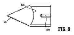
図8は、閉塞器具のさらなる代替実施形態を示す。図8は、内部表面602が概して凸面である閉塞器具600を開示する。内視鏡1000は、器具600内に位置付けられて示され、組み込まれた照明および画像伝送手段202、204に取って代わる。 FIG. 8 shows a further alternative embodiment of the closure device. FIG. 8 discloses an
次に図9を参照すると、閉塞器具700の代替実施形態が開示される。本実施形態では、光透過部材702は、フレネルレンズ704をその近位端に組み込む。フレネルレンズ704は、内視鏡1000の照明システムによって提供される光線を誘導する。フレネルレンズ704の各溝は、隣と若干異なる角度であってもよいが、光を直接的に手術対象へ焦光する、または画像伝送手段のための特定の視野を提供するために、同一焦点距離を利用してもよい。フレネルレンズ704は、ガラス、アクリルガラス、ポリ塩化ビニル、ポリカーボネート、または高密度ポリエチレンを含むが、それらに限定されない、種々の異なる材料から構築されてもよい。光透過部材702の残りの部分は、中空または中実であってもよい。また、フレネルレンズ704は、当業者に理解されるように、画像受信部材として利用され、画像を受信してもよい。 Referring now to FIG. 9, an alternative embodiment of the
形態および詳細の種々の修正および変更は、本発明の精神および範囲から逸脱することなく、本開示の実施形態になされ得ることを理解されるであろう。したがって、前述の説明は、本発明を制限するものとして解釈されるべきではなく、単にその好ましい実施形態の例示として解釈されたい。当業者は、本明細書に添付の請求項によって定義されるように、本発明の範囲および精神内において、他の修正を想定するであろう。したがって、本発明は、特許法によって要求される詳細および特殊性とともに説明されているが、特許請求の範囲および保護請求の範囲は、添付の請求項に記載される。 It will be understood that various modifications and changes in form and detail may be made to the embodiments of the present disclosure without departing from the spirit and scope of the invention. Therefore, the above description should not be construed as limiting the invention, but merely as exemplifications of preferred embodiments thereof. Those skilled in the art will envision other modifications within the scope and spirit of the invention as defined by the claims appended hereto. Thus, while the invention has been described with details and specificities required by the patent law, the appended claims and the protection claims are set forth in the appended claims.
Claims (11)
Translated fromJapanese近位端と遠位端とを有し、かつ、長手方向軸を画定する細長シャフトと、
該細長シャフトの遠位端に隣接して搭載され、かつ、組織に貫入するように適合される光透過部材であって、自身を通る光の通過を可能にするための透明材料を備え、かつ、中空内部チャンバを画定する内部表面と組織に貫入するように適合される外部表面とを有し、さらに、該長手方向軸に対して傾斜している傾斜視野を提供するように適合される、光透過部材と、
照明光を提供する照明手段と、対象の画像を伝達する撮像手段とを備え、
該照明手段が、意図された色の光を発光可能である一連の発光ダイオードから成り、そして、該光透過部材は、宝石状の構成を含む、閉塞器具。An occlusion device for tissue penetration and visualization,
An elongated shaft having a proximal end and a distal end and defining a longitudinal axis;
A light transmissive member mounted adjacent to the distal end of the elongate shaft and adapted to penetrate tissue, comprising a transparent material to allow passage of light therethrough; and An interior surface defining a hollow interior chamber and an exterior surface adapted to penetrate tissue, and further adapted to provide a tilted field of view that is tilted with respect to the longitudinal axis; A light transmissive member;
Illuminating means for providing illumination light, and imaging means for transmitting a target image,
An occlusion device,wherein the illumination means comprises a series of light emitting diodes capable of emitting light of the intended color, and the light transmissive member comprises a jewel-like configuration .
近位端と遠位端とを画定し、かつ、長手方向軸を画定する細長シャフトと、
その遠位端に隣接する透明部材であって、傾斜視野を提供するように適合される屈折表面を含む、透明部材と、
該透明部材に搭載され、かつ、組織を穿刺するための大きさにされる穿刺部材と、
該細長シャフトの遠位端に隣接して掲載される光透過部材と、
照明光を提供する照明手段と、対象の画像を伝達する撮像手段とを備え、
該照明手段が、意図された色の光を発光可能である一連の発光ダイオードから成り、そして、該光透過部材は、宝石状の構成を含む、閉塞器具。A closure device,
An elongate shaft defining a proximal end and a distal end and defining a longitudinal axis;
A transparent member adjacent to its distal end, the transparent member including a refractive surface adapted to provide a tilted field of view;
A puncture member mounted on the transparent member and sized for puncturing tissue;
A light transmissive member posted adjacent to the distal end of the elongate shaft;
Illuminating means for providing illumination light, and imaging means for transmitting a target image,
An occlusion device,wherein the illumination means comprises a series of light emitting diodes capable of emitting light of the intended color, and the light transmissive member comprises a jewel-like configuration .
該照明システムが、意図された色の光を発光可能である一連の発光ダイオードから成り、該閉塞器具は、
少なくとも部分的に該内視鏡を受容するように適合され、近位端と遠位端とを有し、そして、長手方向軸を画定する細長シャフトと、
該細長シャフトの遠位端に隣接して搭載される光透過部材であって、該光透過部材は、組織に貫入するように適合され、中空内部チャンバを画定し、そして、透明材料を備えることにより、該挿入された内視鏡の該照明システムによって投影される光線が、該光透過部材による外向き放射のために該内部チャンバを通過して、該内視鏡の該撮像システムによる該光透過部材を通しての該手術対象の視診を可能にし、該長手方向軸に対して角度オフセットされた視野を提供するように適合される、光透過部材とを備え、該光透過部材は、宝石状の構成を含む、閉塞器具。An optical occlusion device for tissue penetration and visualization of a surgical object by an endoscope connected thereto, the endoscope being illuminated with an illumination system for delivering illumination light and the surgical objectwhat der type of those comprising an imaging system for detecting and transmitting images,
The lighting system consists of a series of light emitting diodes capable of emitting light of the intended color ,
An elongated shaft that is at least partially adapted to receive the endoscope, has a proximal end and a distal end, and defines a longitudinal axis;
A light transmissive member mounted adjacent to a distal end of the elongate shaft, the light transmissive member adapted to penetrate tissue, defining a hollow interior chamber, and comprising a transparent material The light beam projected by the illumination system of the inserted endoscope passes through the internal chamber for outward radiation by the light transmissive member, and the light by the imaging system of the endoscope A light transmissive member adapted to allow viewing of the surgical object through the transmissive member and to provide a field of view that is angularly offset with respect to the longitudinal axis, the light transmissive membercomprising a jewel-like An occlusion devicecomprising aconfiguration .
Applications Claiming Priority (3)
| Application Number | Priority Date | Filing Date | Title |
|---|---|---|---|
| US87589106P | 2006-12-20 | 2006-12-20 | |
| US60/875,891 | 2006-12-20 | ||
| PCT/US2007/026239WO2008079373A1 (en) | 2006-12-20 | 2007-12-20 | Surgical visual obturator |
Publications (2)
| Publication Number | Publication Date |
|---|---|
| JP2010512959A JP2010512959A (en) | 2010-04-30 |
| JP5246959B2true JP5246959B2 (en) | 2013-07-24 |
Family
ID=39562852
Family Applications (1)
| Application Number | Title | Priority Date | Filing Date |
|---|---|---|---|
| JP2009542958AExpired - Fee RelatedJP5246959B2 (en) | 2006-12-20 | 2007-12-20 | Surgical visual occlusion device |
Country Status (6)
| Country | Link |
|---|---|
| US (1) | US20100016664A1 (en) |
| EP (1) | EP2101658A4 (en) |
| JP (1) | JP5246959B2 (en) |
| AU (1) | AU2007338691B2 (en) |
| CA (1) | CA2669983A1 (en) |
| WO (1) | WO2008079373A1 (en) |
Families Citing this family (30)
| Publication number | Priority date | Publication date | Assignee | Title |
|---|---|---|---|---|
| US20100081883A1 (en)* | 2008-09-30 | 2010-04-01 | Ethicon Endo-Surgery, Inc. | Methods and devices for performing gastroplasties using a multiple port access device |
| US20100081863A1 (en)* | 2008-09-30 | 2010-04-01 | Ethicon Endo-Surgery, Inc. | Methods and devices for performing gastrectomies and gastroplasties |
| CN102112163A (en)* | 2008-07-28 | 2011-06-29 | 脊柱诊察公司 | Penetrating member with direct visualization |
| US20100274081A1 (en)* | 2009-04-22 | 2010-10-28 | Tyco Healthcare Group Lp | Visual veress needle assembly |
| EP2471435B1 (en)* | 2009-08-24 | 2014-04-02 | Olympus Medical Systems Corp. | Medical apparatus |
| JP5521195B2 (en)* | 2009-08-26 | 2014-06-11 | 国立大学法人大阪大学 | Endoscope insertion aid |
| JP2011078682A (en)* | 2009-10-09 | 2011-04-21 | Masataka Funada | Puncture needle |
| JP2012040078A (en)* | 2010-08-16 | 2012-03-01 | Masataka Funada | Endoscope |
| US9101315B2 (en) | 2010-11-11 | 2015-08-11 | Specialty Care, Inc. | Cannula system |
| US8821526B2 (en) | 2010-11-11 | 2014-09-02 | Specialtycare, Inc. | Trocar |
| DE102010060877B4 (en) | 2010-11-29 | 2013-08-29 | Reiner Kunz | trocar |
| JP5706762B2 (en)* | 2011-06-10 | 2015-04-22 | オリンパス株式会社 | Observation aid for objective optical system |
| ES2769810T3 (en)* | 2011-10-18 | 2020-06-29 | Covidien Lp | Optical trocar system |
| DE102011056705A1 (en)* | 2011-12-20 | 2013-06-20 | Aesculap Ag | Medical obturator and trocar |
| US9186173B2 (en) | 2012-04-27 | 2015-11-17 | Specialty Care, Inc. | Optical obturator system |
| CA2894544A1 (en) | 2012-12-27 | 2014-07-03 | Covidien Lp | Two-shot molded optical obturator |
| BR112015022987A2 (en)* | 2013-03-15 | 2017-07-18 | Olive Medical Corp | integrated prism trocar visualization for use with angled endoscope |
| EP2829222B1 (en) | 2013-07-24 | 2020-05-27 | Cook Medical Technologies LLC | Locating device |
| DE102015103214A1 (en)* | 2015-03-05 | 2016-09-08 | Karl Storz Gmbh & Co. Kg | trocar |
| US10394012B2 (en)* | 2016-04-01 | 2019-08-27 | INTHESMART Inc. | Endoscopy system |
| KR102486092B1 (en) | 2016-08-17 | 2023-01-06 | 리바운드 세라퓨틱스 코포레이션 | Cannula with Proximally Mounted Camera |
| CN106491191A (en)* | 2016-12-09 | 2017-03-15 | 成都五义医疗科技有限公司 | A kind of visual puncturing pin comprising optical amplification system |
| GB2563240B (en)* | 2017-06-07 | 2019-12-18 | Egyptian Commerce Company Eco | Laparoscopic camera |
| US10722111B2 (en) | 2018-03-13 | 2020-07-28 | Covidien Lp | Optical trocar assembly |
| US10736659B2 (en) | 2018-10-23 | 2020-08-11 | Covidien Lp | Optical trocar assembly |
| CA3130085A1 (en)* | 2019-02-22 | 2020-08-27 | Rebound Therapeutics Corporation | Cannula and obturator with a transparent tip with an opaque component |
| CN113795187A (en)* | 2019-03-06 | 2021-12-14 | 诺亚医疗集团公司 | Single use endoscope, cannula and obturator with integrated vision and illumination |
| US11357542B2 (en) | 2019-06-21 | 2022-06-14 | Covidien Lp | Valve assembly and retainer for surgical access assembly |
| US12042172B2 (en) | 2019-07-03 | 2024-07-23 | Valens Recovery Solutions LLC | Medical implant delivery device |
| DE102019129811A1 (en)* | 2019-11-05 | 2021-05-06 | Olympus Winter & Ibe Gmbh | Surgical instrument and optical obturator for a surgical instrument |
Family Cites Families (21)
| Publication number | Priority date | Publication date | Assignee | Title |
|---|---|---|---|---|
| JPH0758364B2 (en)* | 1989-12-29 | 1995-06-21 | 持田製薬株式会社 | Laser probe and manufacturing method thereof |
| US5562696A (en)* | 1992-11-12 | 1996-10-08 | Cordis Innovasive Systems, Inc. | Visualization trocar |
| US5334150A (en)* | 1992-11-17 | 1994-08-02 | Kaali Steven G | Visually directed trocar for laparoscopic surgical procedures and method of using same |
| AU6487594A (en)* | 1993-06-25 | 1995-01-05 | Ethicon Inc. | Endoscopic visualization access enhancement device |
| US5441041A (en)* | 1993-09-13 | 1995-08-15 | United States Surgical Corporation | Optical trocar |
| US5467762A (en)* | 1993-09-13 | 1995-11-21 | United States Surgical Corporation | Optical trocar |
| US5609562A (en)* | 1993-11-16 | 1997-03-11 | Worldwide Optical Trocar Licensing Corporation | Visually directed trocar and method |
| US5445142A (en)* | 1994-03-15 | 1995-08-29 | Ethicon Endo-Surgery, Inc. | Surgical trocars having optical tips defining one or more viewing ports |
| JP3628717B2 (en)* | 1994-03-17 | 2005-03-16 | オリンパス株式会社 | Stereoscopic endoscope |
| CA2149290C (en)* | 1994-05-26 | 2006-07-18 | Carl T. Urban | Optical trocar |
| US5569292A (en)* | 1995-02-01 | 1996-10-29 | Ethicon Endo-Surgery, Inc. | Surgical penetration instrument with transparent blades and tip cover |
| US5980454A (en)* | 1997-12-01 | 1999-11-09 | Endonetics, Inc. | Endoscopic imaging system employing diffractive optical elements |
| IL138632A (en)* | 2000-09-21 | 2008-06-05 | Minelu Zonnenschein | Multiple view endoscopes |
| JP4477280B2 (en)* | 2000-03-16 | 2010-06-09 | メディガス リミテッド | Gastric fistula wall forming device |
| JP4287273B2 (en)* | 2001-09-24 | 2009-07-01 | アプライド メディカル リソーシーズ コーポレイション | Bladeless obturator |
| JP2003179785A (en)* | 2001-12-11 | 2003-06-27 | Pentax Corp | Imaging equipment |
| JP2003175002A (en)* | 2001-12-11 | 2003-06-24 | Pentax Corp | Imaging equipment |
| EP2545862B1 (en) | 2003-10-03 | 2015-09-30 | Applied Medical Resources Corporation | Bladeless optical obturator with a lock for an optical instrument |
| EP2545870B1 (en)* | 2004-06-29 | 2015-11-04 | Applied Medical Resources Corporation | Insufflating optical surgical instrument |
| US8070767B2 (en)* | 2005-01-28 | 2011-12-06 | Tyco Healthcare Group Lp | Optical penetrating adapter for surgical portal |
| US7470230B2 (en)* | 2005-03-31 | 2008-12-30 | Tyco Healthcare Group Lp | Optical obturator |
- 2007
- 2007-12-20EPEP07853462.5Apatent/EP2101658A4/ennot_activeCeased
- 2007-12-20CACA002669983Apatent/CA2669983A1/ennot_activeAbandoned
- 2007-12-20WOPCT/US2007/026239patent/WO2008079373A1/enactiveApplication Filing
- 2007-12-20JPJP2009542958Apatent/JP5246959B2/ennot_activeExpired - Fee Related
- 2007-12-20AUAU2007338691Apatent/AU2007338691B2/ennot_activeCeased
- 2007-12-20USUS12/513,459patent/US20100016664A1/ennot_activeAbandoned
Also Published As
| Publication number | Publication date |
|---|---|
| WO2008079373A1 (en) | 2008-07-03 |
| AU2007338691B2 (en) | 2013-07-04 |
| EP2101658A4 (en) | 2013-07-03 |
| US20100016664A1 (en) | 2010-01-21 |
| AU2007338691A1 (en) | 2008-07-03 |
| CA2669983A1 (en) | 2008-07-03 |
| JP2010512959A (en) | 2010-04-30 |
| EP2101658A1 (en) | 2009-09-23 |
Similar Documents
| Publication | Publication Date | Title |
|---|---|---|
| JP5246959B2 (en) | Surgical visual occlusion device | |
| US20220167834A1 (en) | Optical coupler for an endoscope | |
| US8414480B2 (en) | Methods and devices for reducing reflection-illuminated artifacts | |
| EP2182833B1 (en) | Endoscope | |
| AU2012243128B2 (en) | Laser video endoscope | |
| US20040158126A1 (en) | Optical trocar | |
| US20100274081A1 (en) | Visual veress needle assembly | |
| JP2011125709A (en) | Visible obturator with tip openings | |
| JPH06169880A (en) | Glare removing apparatus | |
| JPH08503401A (en) | Visual trocar and its visual insertion method | |
| JP2010522025A5 (en) | ||
| US20130310684A1 (en) | Treatment instrument | |
| US20140235946A1 (en) | Optical obturator visualization system | |
| US20080262295A1 (en) | Methods and devices for viewing anatomic structure | |
| US10736659B2 (en) | Optical trocar assembly | |
| US9999443B2 (en) | Instrument head single loader | |
| US20210315442A9 (en) | Optical Coupler for an Endoscope | |
| JP7579263B2 (en) | Cannula system and use of the cannula system | |
| KR20190111615A (en) | Implantable optical member, medical endoscope and implant method of optical member |
Legal Events
| Date | Code | Title | Description |
|---|---|---|---|
| A621 | Written request for application examination | Free format text:JAPANESE INTERMEDIATE CODE: A621 Effective date:20101109 | |
| A521 | Request for written amendment filed | Free format text:JAPANESE INTERMEDIATE CODE: A523 Effective date:20111027 | |
| A131 | Notification of reasons for refusal | Free format text:JAPANESE INTERMEDIATE CODE: A131 Effective date:20120815 | |
| A977 | Report on retrieval | Free format text:JAPANESE INTERMEDIATE CODE: A971007 Effective date:20120815 | |
| A521 | Request for written amendment filed | Free format text:JAPANESE INTERMEDIATE CODE: A523 Effective date:20121102 | |
| TRDD | Decision of grant or rejection written | ||
| A01 | Written decision to grant a patent or to grant a registration (utility model) | Free format text:JAPANESE INTERMEDIATE CODE: A01 Effective date:20130403 | |
| A61 | First payment of annual fees (during grant procedure) | Free format text:JAPANESE INTERMEDIATE CODE: A61 Effective date:20130408 | |
| R150 | Certificate of patent or registration of utility model | Free format text:JAPANESE INTERMEDIATE CODE: R150 | |
| FPAY | Renewal fee payment (event date is renewal date of database) | Free format text:PAYMENT UNTIL: 20160419 Year of fee payment:3 | |
| LAPS | Cancellation because of no payment of annual fees |