JP5246049B2 - Induction heating cooker - Google Patents
Induction heating cookerDownload PDFInfo
- Publication number
- JP5246049B2 JP5246049B2JP2009136974AJP2009136974AJP5246049B2JP 5246049 B2JP5246049 B2JP 5246049B2JP 2009136974 AJP2009136974 AJP 2009136974AJP 2009136974 AJP2009136974 AJP 2009136974AJP 5246049 B2JP5246049 B2JP 5246049B2
- Authority
- JP
- Japan
- Prior art keywords
- power
- opening
- exhaust port
- circuit board
- main body
- Prior art date
- Legal status (The legal status is an assumption and is not a legal conclusion. Google has not performed a legal analysis and makes no representation as to the accuracy of the status listed.)
- Active
Links
Images


Landscapes
- Induction Heating Cooking Devices (AREA)
Description
Translated fromJapanese本発明は、誘導加熱調理器に関するものである。 The present invention relates to an induction heating cooker.
従来、この種の誘導加熱調理器としては、例えば、特許文献1(特開昭61−260585号公報)に記載されているようなものがあった。 Conventionally, as this type of induction heating cooker, there has been one as described in Patent Document 1 (Japanese Patent Laid-Open No. 61-260585), for example.
特許文献1では、電磁調理器の電源入力部と単相交流電源の各ラインとを接続する2個のチョークコイルと、チョークコイルの電磁調理器側の各端子を接続するバイパスコンデンサと、前記チョークコイルを覆うカバーとを備え、カバーは、誘導加熱コイルに対向する面が非磁性金属板からなり、他の面が開口を有する構成としている。 In Patent Document 1, two choke coils that connect a power input unit of an electromagnetic cooker and each line of a single-phase AC power supply, a bypass capacitor that connects each terminal of the choke coil on the electromagnetic cooker side, and the choke A cover that covers the coil, and the cover is configured such that the surface facing the induction heating coil is made of a nonmagnetic metal plate and the other surface has an opening.
しかしながら、近年、この種の誘導加熱調理器は、総電力5800Wの機器が主流となっており、200Vであるが、約29Aの電流が流れるため、前記従来の構成では、電源部に配したチョークコイル、コンデンサ等を含む電子部品の温度上昇が電源経路接続部内の電気抵抗によって高くなってしまう。部品によっては、冷却対策が必要となってしまい、非磁性金属板で覆うことで対ノイズ性の向上は達成されるが、冷却性能の悪化というトレードオフを有しているという課題を有していた。また、チョークコイル等、電源経路接続部内の部品の冷却性能向上のために、排気口近傍に電源経路接続部を設け、電源経路接続部の発熱を直接機器本体に排気させるといった手段も考えられるが、使用中に鍋から吹き零れた液体が排気口から電源経路接続部に侵入し、機器の故障となる危険性も生じるという課題も有していた。 However, in recent years, this type of induction heating cooker has been mainly used for equipment with a total power of 5800 W and is 200 V. However, since a current of about 29 A flows, the choke provided in the power supply section in the conventional configuration. The temperature rise of electronic components including coils, capacitors and the like is increased by the electric resistance in the power supply path connection portion. Depending on the part, cooling measures are required, and by covering with a non-magnetic metal plate, improvement in noise resistance is achieved, but there is a problem that there is a trade-off of deterioration in cooling performance It was. In addition, in order to improve the cooling performance of components in the power path connection section such as a choke coil, a means of providing a power path connection section in the vicinity of the exhaust port and exhausting heat generated in the power path connection section directly to the device main body can be considered. In addition, there has been a problem that the liquid that has been blown from the pan during use enters the power supply path connection portion from the exhaust port, resulting in a risk of equipment failure.
本発明は、前記従来の課題を解決するもので、電源経路接続部への外部からの液体の浸入を防ぐとともに、電源経路接続部の冷却性能を向上する誘導加熱調理器を提供することを目的とする。 The present invention solves the above-described conventional problems, and an object thereof is to provide an induction heating cooker that prevents liquid from entering the power path connecting portion from the outside and improves the cooling performance of the power path connecting portion. And
前記従来の課題を解決するために、本発明の誘導加熱調理器は、本体を構成する外郭と、本体上面に設けられた被加熱物を戴置するためのトッププレートと、前記トッププレートの下方に設けられた前記被加熱物を誘導加熱する加熱コイルと、本体前方に設けた開口部と、前記開口部を通して本体外の空気を吸気するファンと、前記ファンより後方へ送風された冷却風の下流側に設けられ前記加熱コイルの出力を制御する回路基板と、前記外郭後方の上面に設けられた前記冷却風の出口となる排気口と、前記外郭後部を貫通して商用電源を供給する電源コードと、前記電源コードと前記回路基板に導く電源経路とを接続する電源経路接続部と、前記外郭後側面に取り付けられ、前記電源経路接続部を覆うようにダクトを形成する金属カバーとを備え、前記ダクトは下方と上面に開口部を有し、前記上面の開口部は上方から見て前記排気口と重ならないように前記排気口の近傍で、かつ前記排気口から左右方向にずらした位置に設けられ、前記冷却風が前記下方の開口部から前記上面の開口部を通り、前記上面の開口部から前記排気口に通ずるように構成したことを特徴とする。In order to solve the above-mentioned conventional problems, an induction heating cooker according to the present invention includes an outer shell constituting a main body, a top plate for placing an object to be heated provided on the upper surface of the main body, and a lower portion of the top plate. A heating coil for inductively heating the object to be heated, an opening provided in front of the main body, a fan for sucking air outside the main body through the opening, and cooling air blown rearward from the fan A circuit board provided on the downstream side for controlling the output of the heating coil, an exhaust port serving as an outlet for the cooling air provided on the upper surface behind the outer shell, and a power source for supplying commercial power through the rear portion of the outer shell code, and the cord and the circuit power supply path connecting unit for connecting the power supply path leading to the substrate, mounted on the outerrear side, and a metal cover forming a duct so as to cover the power supply path connecting portion Wherein the duct has an opening downward andan upper surface, an opening portion of theupper surface inthe vicinity of the exhaust port so as not to overlap with the exhaust port as viewed fromabove, and shifted in the lateral direction from the exhaust port provided in a position, the cooling air passes through the opening in the top surface from the opening of the lower, and characterized by being configured from an opening ofthe upper surfaceso that leading to the exhaust port.
これによって、電源経路接続部の温度上昇を抑制できるとともに、電源経路接続部への
加熱コイルからの漏洩磁束やスイッチング電源から発せられる電磁ノイズからのノイズ遮蔽性能を向上することができる。また、さらに、ダクトの上面開口部を排気口と重ならないように配置することで、使用者が調理中に排気口に水やスープ等の液体を零してしまった場合においても、電源経路接続部には液体は浸入せず、ショートの危険がなく安心して使用することができる。As a result, the temperature rise of the power supply path connecting portion can be suppressed, and the noise shielding performance from the magnetic flux leaked from the heating coil to the power supply path connecting portion and the electromagnetic noise generated from the switching power supply can be improved. In addition, by arranging the top opening of the duct so that it does not overlap the exhaust port, even if the user spills liquid such as water or soup into the exhaust port during cooking, the power path connection Liquid does not enter the part, so there is no danger of short circuit and it can be used safely.
本発明の誘導加熱調理器は、上下に開口部を有し、電源経路接続部を覆う金属製のダクト上方の開口部と、排気口を機器上方から見て重ならないように設けることで、機器後方に設けられた電源経路接続部を排気口からの水の浸入を防ぎつつ、冷却性能およびノイズ遮蔽性能を向上することができる。 The induction heating cooker of the present invention has an opening on the top and bottom, and is provided so that the opening above the metal duct covering the power path connection portion and the exhaust port do not overlap when viewed from above the device. Cooling performance and noise shielding performance can be improved while preventing the ingress of water from the exhaust port through the power path connecting portion provided at the rear.
第1の発明は、本体を構成する外郭と、本体上面に設けられた被加熱物を戴置するためのトッププレートと、トッププレートの下方に設けられた被加熱物を誘導加熱する加熱コイルと、本体前方に設けた開口部と、開口部を通して本体外の空気を吸気するファンと、ファンより後方へ送風された冷却風の下流側に設けられ加熱コイルの出力を制御する回路基板と、外郭後方の上面に設けられた冷却風の出口となる排気口と、外郭後部を貫通して商用電源を供給する電源コードと、電源コードの端子と回路基板に導く電源経路とを接続する電源経路接続部と、外郭後側面に電源経路接続部を覆う金属により形成されたダクトとを備え、ダクトは下方と上面に開口部を有し、上面の開口部は上方から見て排気口と重ならないように排気口の近傍で、かつ前記排気口から左右方向にずらした位置に設けられ、前記冷却風が前記下方の開口部から前記上面の開口部を通り、前記上面の開口部から排気口に通ずるように構成することにより、電源経路接続部の温度上昇を抑制できるとともに、電源経路接続部への加熱コイルからの漏洩磁束やスイッチング電源から発せられる電磁ノイズからのノイズ遮蔽性能を向上することができる。また、さらに、ダクトの上面開口部を排気口と重ならないように配置することで、使用者が調理中に排気口に水やスープ等の液体を零してしまった場合においても、電源経路接続部には液体は浸入せず、ショートの危険がなく安心して使用することができる。1st invention, the outline which comprises a main body, the top plate for mounting the to-be-heated object provided in the main body upper surface, the heating coil which carries out induction heating of the to-be-heated object provided under the top plate, An opening provided in the front of the main body, a fan that sucks air outside the main body through the opening, a circuit board that is provided downstream of the cooling air blown rearward from the fan and controls the output of the heating coil, and an outer shell Power supply path connection that connects the exhaust outlet that is the outlet of the cooling air provided on the rear upper surface, the power cord that feeds the commercial power through the rear part of the outer shell, and the power supply path that leads the terminal of the power cord and the circuit board And a duct made of metal covering the power path connection portion on the outerside of the outer shell, the duct has openings on the lower andupper surfaces, and the opening on theupper surface does not overlap the exhaust port when viewed from abovein the vicinity of the exhaust portAnd provided at a position shifted in the lateral direction from the exhaust port by the cooling air passes through the opening in the top surface from the opening of the lower, configuredto lead to the exhaust port from the opening ofthe upper surface, While suppressing the temperature rise of a power path connection part, the noise shielding performance from the leakage magnetic flux from the heating coil to a power path connection part or the electromagnetic noise emitted from a switching power supply can be improved. In addition, by arranging the top opening of the duct so that it does not overlap the exhaust port, even if the user spills liquid such as water or soup into the exhaust port during cooking, the power path connection Liquid does not enter the part, so there is no danger of short circuit and it can be used safely.
第2の発明は、特に、第1の発明のダクトが電源経路接続部と回路基板の間に設けられたノイズフィルタをさらに覆うとすることにより、ノイズフィルタの冷却性能を向上することができるとともに、ノイズフィルタのノイズ遮蔽性能を向上させることができる。 In the second invention, in particular, the duct of the first invention further covers the noise filter provided between the power path connecting portion and the circuit board, thereby improving the cooling performance of the noise filter. The noise shielding performance of the noise filter can be improved.
第3の発明は、特に、第1または第2の発明の回路基板と外郭底面の間に底面と略垂直な側壁を設け、ファンからの冷却風を回路基板と外郭底面と側壁に囲まれた経路に流すとすることにより、冷却風をダクト内に効率よく流すことができ、冷却性能を向上することができる。 In the third invention, in particular, a side wall substantially perpendicular to the bottom surface is provided between the circuit board of the first or second invention and the outer bottom surface, and the cooling air from the fan is surrounded by the circuit board, the outer bottom surface and the side wall. By letting it flow in the path, the cooling air can be efficiently flowed into the duct, and the cooling performance can be improved.
第4の発明は、特に、第1または第2の発明の回路基板と外郭底面の間に底面と略平行な仕切板を設け、ファンからの冷却風を仕切板と外郭底面の間に流すとすることにより、冷却風をダクト内に効率よく流すことができ、冷却性能を向上することができる。 In the fourth invention, in particular, when a partition plate substantially parallel to the bottom surface is provided between the circuit board of the first or second invention and the outer bottom surface, the cooling air from the fan is allowed to flow between the partition plate and the outer bottom surface. By doing so, the cooling air can be efficiently flowed into the duct, and the cooling performance can be improved.
第5の発明は、特に、第4の発明の仕切板と外郭底面に当接する略垂直な側壁を設け冷却風を仕切板と外郭底面と側壁に囲まれた経路に流すとすることにより、冷却風をダクト内に効率よく流すことができ、冷却性能を向上することができる。 In particular, the fifth aspect of the invention provides cooling by providing a substantially vertical side wall that abuts against the partition plate of the fourth aspect of the invention and the bottom surface of the outer shell, and flowing cooling air through a path surrounded by the partition plate, the outer bottom surface, and the side wall. Wind can be efficiently flowed into the duct, and the cooling performance can be improved.
第6の発明は、特に、第5の発明の仕切板と外郭底面と側壁との間に空間をさらに構成し、前記空間は、排気口と連結した経路を構成しているとすることにより、排気口から侵入した水等の液体が排気口から前記空間に流入することで、冷却風の経路に水等の液体が侵入し液体がファンの風に乗って電源経路接続部に付着することがなく、使用者が調理中に排気口に水やスープ等の液体を零してしまった場合においても、ショートの危険がなく、安心して使用することができる。 In the sixth aspect of the invention, in particular, a space is further formed between the partition plate of the fifth aspect of the invention, the outer bottom and the side wall, and the space constitutes a path connected to the exhaust port. When liquid such as water that has entered from the exhaust port flows into the space from the exhaust port, liquid such as water may enter the cooling air path, and the liquid may ride on the wind of the fan and adhere to the power path connection part. In addition, even when the user spills liquid such as water or soup into the exhaust port during cooking, there is no danger of short-circuiting, and the user can use it with peace of mind.
以下、本発明の実施の形態について、図面を参照しながら説明する。なお、本実施の形態によって、本発明が限定されるものではない。 Hereinafter, embodiments of the present invention will be described with reference to the drawings. Note that the present invention is not limited to the present embodiment.
(実施の形態1)
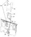
図1は本実施の形態における誘導加熱調理器の断面図。(Embodiment 1)
FIG. 1 is a cross-sectional view of an induction heating cooker in the present embodiment.
図2は本実施の形態における誘導加熱調理器の内部の構成を示す斜視概略図。 FIG. 2 is a schematic perspective view showing an internal configuration of the induction heating cooker in the present embodiment.
図3は本実施の形態における誘導加熱調理器のノイズフィルタ取り付け部詳細図。 FIG. 3 is a detailed view of the noise filter mounting portion of the induction heating cooker in the present embodiment.
図4は本実施の形態における誘導加熱調理器のブロック図。 FIG. 4 is a block diagram of the induction heating cooker in the present embodiment.
図に示すように、金属で形成された誘導加熱調理器の本体外郭11は、キッチン12の上面開口部から挿入設置されている。本体外郭11上面には、本体外郭11の上面を覆うとともに本体外郭11をキッチンの上面開口部から挿入設置したときに本体外郭11を支えるトップユニット部13、トップユニット部13を構成する鍋などを載せる結晶化ガラスで形成したトッププレート14とトッププレート下面を支える金属製のアンダーフレーム15、本体外郭11内のトップユニット部13の下には、左側に左加熱コイル16a、右側に右加熱コイル16bが置かれている。また本体の左側で、左加熱コイル16aの下方にロースター17が置かれている。ロースター17の右側で、右加熱コイル16bの下方には、基板ベース18で保持した、左加熱コイル16aと右加熱コイル16bに電流を供給し駆動制御する回路基板19が配置されている。回路基板19には、整流回路20とインバータ回路21とスイッチング電源22と制御回路23が設けられている。また、回路基板19の前側に近接して本体外郭11内に冷却風を送り込む冷却ファン24を、冷却ファン24の前側に加熱操作設定を行う操作部25を配置している。回路基板19後方の外郭後側面に電源経路接続部基板ホルダ26に取り付けたられた電源経路接続部基板27を設け、電源経路接続部基板27の下方の外郭後側面開口穴より挿入された電源コード28の電源コード電源接続部29を電源経路接続部基板27の下側の端子台に端子ねじにより接続している。また、電源経路接続部基板27の上方にはノイズフィルタ基板ホルダ30に取り付けられたノイズフィルタ31が、電源経路接続部基板27と同様、外郭後側面に取り付けられ、電源経路接続部基板27から出力された電流が、ノイズフィルタ31を通過して制御回路23に供給される。また、電源コードアース接続部32は、電源経路接続部基板27の下方で外郭後側面に締め付けて接続している。電源経路接続部基板27、電源コード電源接続部29および電源コードアース接続部30の前面と左右を囲うように金属製の電源経路接続部カバー33を形成しており、電源経路接続部カバー33は外郭後
側面に当接するようにセットされ、電源経路接続部カバー33の一部に設けたカバーねじ締め部34は本体外郭11後側面とアンダーフレーム15とで挟んでねじで共締めをする構成となっており、アンダーフレーム15で電源経路接続部基板27上部を覆っている。電源コード28は、電源接続線2本とアース線1本が束になった3線一体式の構成となっている。また、電源経路接続部カバー33には、任意のノイズ遮蔽効果が損なわれない範囲で、カバー通気穴35が設けられている。またさらに、基板ベース18の下面に、冷却ファン24から電源経路接続部カバー下方の開口部33aに通気経路を構成するように外郭底と基板ベース18との間に空間を設けている。さらに、ロースター17と、基板ベース18、電源経路接続部カバー33、冷却ファン24および操作部25との間に金属製の中仕切り板36を配している。また、本体外郭11後方の上部トップユニット部13に冷却風の出口となる排気口37を設けている。As shown in the figure, the
操作部25は、操作部外方を形成する操作部ケース38に内蔵され、操作部25が開閉により操作部ケース38内に収納されたり、操作部ケース38外方に露出されたりする形態となっている。操作部25は、最上部に配した操作用押しボタン部39と、その操作用押しボタン部39下方に設けたボタンの操作を検知し回路基板19へ信号を伝送するスイッチを有する操作基板40と、操作基板を支持する操作基板ベース41と、操作基板ベース41を左右下方にて支持する左右支持部42と、操作基板ベースと左右支持部の前面を塞ぐ前面板43とで構成している。また、操作部25上面の奥の略中央に幅が約50mmの操作部25上面凸部を設け、また操作部ケース38の上面の略中央に幅約50mmの下向き凸部を設けている。左右支持部42の左右の下部とそれに対向した操作部ケース38の側部にシャフト44を通し、この部分を基点に開閉回動することにより、操作部25が操作部25ケース内に収納されたり、操作部25ケース外方に露出されたりする。この際、操作部25の上面の奥に設けた操作部25上面凸部は、操作部ケース38の内面と隙間をもって回動する。操作部25が開いたときには、操作部25上面凸部が、操作部ケース38の上面に設けた下向き凸部に当接し、回動が止まる。 The
操作部25後方の操作部ケース38に設けた操作部ケース開口穴45を設けており、操作部ケース38と操作部25の間に有る約4mmの隙間と連続した通気経路を構成している。 An operation unit
冷却ファン24は操作部ケース38の奥に位置し、冷却ファン24の奥に回路基板19が配されている。ファン吸気口46は操作部ケース38側で排気口は回路基板側となる。 The cooling
次に、冷却ファン24の冷却風の流れについて説明する。図1および図2に冷却風の流れを矢印で記載する。 Next, the flow of cooling air from the cooling
まず、冷却風は操作部ケース38と操作部25の間に有る約4mmの隙間から外気が入り、操作部後方の操作部ケース38に設けた操作部ケース開口穴45を通って、ファン吸気口46へ吸い込まれる。吸い込まれた空気は、大きく4経路に分けられて排出される。 First, the cooling air enters from the gap of about 4 mm between the
1経路目は、回路基板19と外郭底の空間で形成された電源経路接続部カバー下方開口部33aに通じる通気経路に噴出され、通気経路を通って電源経路接続部カバー下方開口部33aに吹き込んだ冷却風は、電源経路接続部カバー33と外郭後側面とで形成された電源経路接続部基板27を内部に有する通気経路を通って、電源経路接続部カバー上方開口部33bから排出され、さらに電源経路接続部カバー上方開口部33bと重ならないように設けられたトップユニット部13後方の排気口37へと流れ外へ排出される経路。 The first path is blown into the ventilation path that leads to the power path connection section cover
2経路目は、冷却ファン24により基板ベース18に取り付けられているスイッチング素子やダイオードブリッジといった発熱部品を有する回路基板19へ噴出され、その後、
後方の電源経路接続部カバー33のノイズ遮蔽効果が損なわれない範囲であけられたカバー通気穴35へ流入し、電源経路接続部カバー上方開口部33bまたは更に設けた別のカバー通気穴から排出され、さらに本体トップユニット部13後方に設けられた排気口37へと流れ外へ排出される経路。The second path is ejected to the
It flows into the
3経路目は、冷却ファン24により右加熱コイル16bを経由しながら本体トップユニット部13後方に設けられた排気口37へと流れ外へ排出される経路。 The third path is a path that is discharged out of the flow to the
4経路目は、冷却ファン24により左加熱コイル16aを経由しながら本体トップユニット部13後方に設けられた排気口37へと流れ外へ排出される経路である。 The fourth path is a path that is discharged out of the flow to the
本構成の1経路目の、回路基板19と外郭底の空間で形成された、ファンからカバー下方の開口部33aに通じる通気経路へ噴出され、通気経路を通ってカバー下方の開口部下穴に吹き込み、電源経路接続部カバー33と外郭後側面で形成された電源経路接続部基板27を内部に有する通気経路を通って、カバー上方開口部33bから排出される通気経路構成により、電源経路接続部基板27を冷却することができる。 The first path of this configuration, which is formed in the space between the
また、2経路目の、冷却ファン24により基板ベース18に取り付けられているスイッチング素子やダイオードブリッジといった発熱部品を有する回路基板19へ噴出され、その後、後方の電源経路接続部カバー33のノイズ遮蔽効果が損なわれない範囲であけられたカバー通気穴35へ流入し、電源経路接続部カバー上方の開口部33bまたは更に設けた別のカバー通気穴から排出され、さらに本体トップユニット13後方に設けられた排気口37へと流れ外へ排出される通気経路構成により、特に電源経路接続部基板27の上方の1経路目で冷却効果が得られない箇所などを局部的に冷却することができ、1経路目とあわせて、電源経路接続部27およびノイズフィルタ31の冷却向上に効果を発揮することができる。また、この際、中仕切板36により、加熱時のロースター17からの熱影響を遮蔽し、本体右側の冷却経路に対する熱影響を低減することができ、電源経路接続部基板27およびノイズフィルタ31の冷却性能向上を行うことができる。 Further, the second path is ejected to the
次に、回路接続および回路動作について説明する。図4にブロック図を示す。 Next, circuit connection and circuit operation will be described. FIG. 4 shows a block diagram.
商用電源と機器を接続するため電源コード28の電源コード電源接続部29が電源経路接続部基板27に接続される、そして電源経路接続部基板27と回路基板19の整流回路20がノイズフィルタを介して接続され、回路基板19内で整流回路20とインバータ回路21が接続されており、インバータ回路21に加熱コイル16が接続されている。また回路基板19内でスイッチング電源22と制御回路23が接続され、制御回路23と操作部25が接続されている。 In order to connect the commercial power supply and the device, the power cord
ノイズフィルタ31は発生するスイッチングノイズが商用電源の電源ラインに漏洩することを防止する。 The
整流回路20は商用電源の交流を直流に変換する。インバータ回路21はスイッチング素子を数十kHzでスイッチングし加熱コイル16に高周波電流を発生させる。加熱コイルに高周波電流を発生させることで調理鍋等の負荷底部に誘導電流が発生し負荷が加熱される。 The rectifier circuit 20 converts the alternating current of the commercial power source into a direct current. The inverter circuit 21 switches the switching element at several tens of kHz and generates a high frequency current in the
スイッチング電源22はスイッチング素子を数百kHz程度でスイッチングすることで商用電源電圧から制御回路23に供給する直流電圧をつくる。制御回路は操作部25からの情報とインバータ回路21からの情報に基づき、誘導加熱調理器の加熱を制御する。使用者は操作部25を操作することで調理時の火力調整を行う。 The switching
ノイズフィルタ31は発生するスイッチングノイズが商用電源の電源ラインに漏洩することを防止するためのものであるが、ノイズフィルタ31は他の部品が発する漏洩磁束の影響によって、ノイズ遮断性能が低下してしまう。 The
そこで本構成では、電源コード電源接続部29および電源コードアース接続部32の前面と左右を囲うように金属製の電源経路接続部カバー33を形成しており、電源経路接続部カバー33は外郭後側面に当接するようにセットされ、電源経路接続部カバー33の一部に設けた電源経路接続部カバーねじ締め部34は本体外郭後側面とアンダーフレーム15とで挟んでねじで共締めをする構成となっており、接地電位部分としてのアースに接続されているため、加熱コイル16で発生する漏洩磁束やスイッチング電源から発せられる電磁ノイズは本体外郭11および、電源経路接続部カバー33によってシールドされ接地電位部分としてのアースに吸収されるため、ノイズ遮蔽性能を向上することができる。また、ノイズフィルタ31は本体外郭最後方部に位置しており、スイッチング電源22や加熱コイル16から距離も遠くとれ、他の部品が発する漏洩磁束のノイズフィルタ31への影響を低減することができる。またさらに電源経路接続部の下方に電源コード28の本体挿入口を設けることで、スイッチング電源22や加熱コイル16から距離が遠くとれ、他の部品が発する漏洩磁束の電源経路接続部27から商用電源ラインである電源コード28への影響を低減することができる。また、電源経路接続部27下方の外郭後側面開口穴より挿入された電源コード28の電源コード電源接続部29を電源経路接続部基板27の下側の端子台に端子ねじにより接続しているため、本体内に電源コード28が挿入されて、基板に接続されるまでの電源コード28のリードの長さが短くでき、他の部品が発する漏洩磁束から影響されるリードの長さが短いため、電源経路接続部27から商用電源ラインである電源コードへの影響を低減することができる。電源コードアース接続部32は、電源経路接続部基板27の下方で外郭後側面に締め付けて接続しているので、これもリードの長さが短くでき、他の部品が発する漏洩磁束から影響されるリードの長さが短いため、アース線への影響を低減することができ、電源経路接続部27から商用電源ラインである電源コード28への影響を低減することができる。また金属製のアンダーフレーム15で電源経路接続部基板27上部を覆う構成とすることにより、加熱コイル16で発生する漏洩磁束はアンダーフレーム15により遮蔽され、電源経路接続部27へのノイズ遮蔽性能を向上することができる。またさらに、電源経路接続部カバー33の一部を金属製の本体外郭にねじにより締め付ける構成としたことにより、確実に電源経路接続部カバー33がねじ締めによりアースにつながり、他の部品が発する漏洩磁束が接地電位部分としてのアースに吸収されるため、ノイズ遮蔽性能を向上することができる。 Therefore, in this configuration, a metal power path connecting
以上のように本実施の形態において、電源経路接続部基板27および電源コード電源接続部29の前面と左右を囲う金属により形成された電源経路接続部カバー33により、加熱コイル16から電源経路接続部基板27への漏洩磁束やスイッチング電源22から発せられる電磁ノイズからのノイズ遮蔽性能を向上することができる。また、調理器本体外の空気を吸気する冷却ファン24により送風された冷却風を電源経路接続部基板27内に通気し、電源経路接続部27の上方のカバー外へ排気する通気経路を設け、電源経路接続部カバー上方開口部33bとトップユニット13後方の排気口37が上方から見て重ならないように配置することで、電源経路接続部基板27の構成部品を冷却することができるとともに、使用中に液体が零れた際にも、電源経路接続部27に液体が侵入し、ショートの危険を防ぐことができる。 As described above, in the present embodiment, the power
(実施の形態2)
さらに、電源経路接続部基板27は、電源コード28から供給される商用電源を回路基板19に供給するために、電源コード電源接続部29を接続する端子台を備えているが、チョークコイル、コンデンサをさらに有し、ノイズフィルタ31を兼ねているものでも良
い。特にコイルは自己発熱が大きい冷却対策が必要な部品であり、部品の配置によっては、近傍のコンデンサの温度も上昇させてしまうこともあるため、電源経路接続部カバー33がコイル、コンデンサ等のノイズフィルタ31を覆うことでノイズフィルタの冷却性能がさらに向上する。(Embodiment 2)
Further, the power
(実施の形態3)
さらに、図5に示すように回路基板19と本体外郭11底面の間に底面と略垂直な側壁47を設け、冷却ファン24からの冷却風を回路基板19と本体外郭11底面と側壁47に囲まれた経路に流すことにより、電源経路接続部カバー33内に効率よく流すことができ、冷却性能を向上することができる。(Embodiment 3)
Further, as shown in FIG. 5, a
(実施の形態4)
さらに、回路基板19と本体外郭11底面の間に底面と略平行な仕切板48を設け、冷却ファン24からの冷却風を仕切板48と本体外郭11底面との間に流すことにより、冷却風を電源経路接続部カバー33内に効率よく流すことができ、冷却性能を向上することができる。(Embodiment 4)
Further, a
(実施の形態5)
さらに、図7に示すように仕切板48と本体外郭11底面に当接する略垂直な側壁47を設け冷却風を仕切板48と本体外郭11底面と側壁47に囲まれた経路に流すことにより、冷却風を電源経路接続部カバー33内に効率よく流すことができ、冷却性能を向上することができる。(Embodiment 5)
Further, as shown in FIG. 7, by providing a substantially
(実施の形態6)
さらに、図8に示すように仕切板48と本体外郭11底面と側壁47との間に空間49をさらに設け、図に矢印で記載した通風経路50と分離することにより、排気口37から侵入した液体は図に矢印で記載した流入経路51を通り空間49内に流れ落ちるため、通風経路50に液体が侵入し液体が冷却ファン24の風に乗って電源経路接続部基板27に付着することがなく、使用者が調理中に排気口37に水やスープ等の液体を零してしまった場合においてもショートの危険がなく、安心して使用することができる。(Embodiment 6)
Further, as shown in FIG. 8, a
以上のように、本発明にかかる誘導加熱調理器は、上下に開口部を有し、電源経路接続部を覆う金属製のダクト上方の開口部と、排気口を機器上方から見て重ならないように設けることで、機器後方に設けられた電源経路接続部を排気口からの水の浸入を防ぎつつ、冷却性能およびノイズ遮蔽性能を向上することができるので、電源経路接続部と排気口とを有する業務用あるいは家庭用の加熱調理機器等の用途にも適用できる。 As described above, the induction heating cooker according to the present invention has openings on the upper and lower sides so that the opening above the metal duct covering the power supply path connection portion and the exhaust port do not overlap when viewed from above the device. Since the cooling performance and noise shielding performance can be improved while preventing the intrusion of water from the exhaust port, the power path connection portion and the exhaust port are provided. The present invention can also be applied to uses such as commercial or household cooking equipment.
11 本体外郭(外郭)
12 キッチン
13 トップユニット部
14 トッププレート
15 アンダーフレーム
16a 左加熱コイル(加熱コイル)
16b 右加熱コイル(加熱コイル)
17 ロースター
18 基板ベース
19 回路基板
24 冷却ファン(ファン)
25 操作部
26 電源経路接続部基板ホルダ
27 電源経路接続部基板(電源経路接続部)
28 電源コード
29 電源コード電源接続部
30 ノイズフィルタ基板ホルダ
31 ノイズフィルタ
32 電源コードアース接続部
33 電源経路接続部カバー(金属カバー、ダクト)
33a 電源経路接続部カバー下方開口部(下方の開口部)
33b 電源経路接続部カバー上方開口部(上方の開口部)
34 カバーねじ締め部
35 カバー通気穴
36 中仕切板
37 排気口
38 操作部ケース
39 操作用押しボタン部
40 操作基板
41 操作基板ベース
42 左右支持部
43 前面板
44 シャフト
45 操作部ケース開口穴(前方に設けた開口部)
46 ファン吸気口
47 側壁
48 仕切板
49 空間
50 通風経路
51 流入経路11 Body shell (outer shell)
12
16b Right heating coil (heating coil)
17
25
28
33a Power path connection part cover lower opening (lower opening)
33b Power path connection portion cover upper opening (upper opening)
34 Cover
46
Claims (6)
Translated fromJapanese本体上面に設けられた被加熱物を戴置するためのトッププレートと、
前記トッププレートの下方に設けられた前記被加熱物を誘導加熱する加熱コイルと、
本体前方に設けた開口部と、
前記開口部を通して本体外の空気を吸気するファンと、
前記ファンより後方へ送風された冷却風の下流側に設けられ前記加熱コイルの出力を制御する回路基板と、
前記外郭後方の上面に設けられた前記冷却風の出口となる排気口と、
前記外郭後部を貫通して商用電源を供給する電源コードと、
前記電源コードと前記回路基板に導く電源経路とを接続する電源経路接続部と、
前記外郭後側面に取り付けられ、前記電源経路接続部を覆うようにダクトを形成する金属カバーと、
を備え、
前記ダクトは下方と上面に開口部を有し、前記上面の開口部は、上方から見て前記排気口と重ならないように前記排気口の近傍で、かつ前記排気口から左右方向にずらした位置に設けられ、前記冷却風が前記下方の開口部から前記上面の開口部を通り、前記上面の開口部から前記排気口に通ずるように構成したことを特徴とする誘導加熱調理器。An outer shell constituting the main body,
A top plate for placing an object to be heated provided on the upper surface of the main body;
A heating coil for inductively heating the object to be heated provided below the top plate;
An opening provided in front of the main body,
A fan that sucks air outside the main body through the opening;
A circuit board provided on the downstream side of the cooling air blown rearward from the fan to control the output of the heating coil;
An exhaust port serving as an outlet for the cooling air provided on the upper surface behind the outer shell;
A power cord for supplying commercial power through the outer rear portion;
A power path connecting portion for connecting the power cord and a power path leading to the circuit board;
A metal cover that is attached to therear side surface of the outer shell and forms a duct so as to cover the power path connecting portion;
With
Position the duct has an opening downward andan upper surface, an opening portion of theuppersurface,in the vicinity of the exhaust port so as not to overlap with the exhaust port as viewed fromabove, and which is shifted in the lateral direction from the exhaust port provided, the cooling wind passes through the opening in the top surface from the opening of the lower, the induction cooking device, characterized in that configuredas leading to the exhaust port from the opening ofthe top surface.
Priority Applications (1)
| Application Number | Priority Date | Filing Date | Title |
|---|---|---|---|
| JP2009136974AJP5246049B2 (en) | 2009-06-08 | 2009-06-08 | Induction heating cooker |
Applications Claiming Priority (1)
| Application Number | Priority Date | Filing Date | Title |
|---|---|---|---|
| JP2009136974AJP5246049B2 (en) | 2009-06-08 | 2009-06-08 | Induction heating cooker |
Publications (2)
| Publication Number | Publication Date |
|---|---|
| JP2010282910A JP2010282910A (en) | 2010-12-16 |
| JP5246049B2true JP5246049B2 (en) | 2013-07-24 |
Family
ID=43539473
Family Applications (1)
| Application Number | Title | Priority Date | Filing Date |
|---|---|---|---|
| JP2009136974AActiveJP5246049B2 (en) | 2009-06-08 | 2009-06-08 | Induction heating cooker |
Country Status (1)
| Country | Link |
|---|---|
| JP (1) | JP5246049B2 (en) |
Cited By (1)
| Publication number | Priority date | Publication date | Assignee | Title |
|---|---|---|---|---|
| KR20180025010A (en)* | 2016-08-31 | 2018-03-08 | 엘지전자 주식회사 | A combination cooker including induction heater |
Family Cites Families (4)
| Publication number | Priority date | Publication date | Assignee | Title |
|---|---|---|---|---|
| JP3317284B2 (en)* | 1999-09-07 | 2002-08-26 | 松下電器産業株式会社 | Built-in induction heating cooker |
| JP2004063121A (en)* | 2002-07-25 | 2004-02-26 | Matsushita Electric Ind Co Ltd | High frequency heating equipment |
| JP3786117B2 (en)* | 2004-01-29 | 2006-06-14 | 松下電器産業株式会社 | Induction heating cooker |
| JP4492365B2 (en)* | 2005-01-28 | 2010-06-30 | パナソニック株式会社 | Cooker |
- 2009
- 2009-06-08JPJP2009136974Apatent/JP5246049B2/enactiveActive
Cited By (2)
| Publication number | Priority date | Publication date | Assignee | Title |
|---|---|---|---|---|
| KR20180025010A (en)* | 2016-08-31 | 2018-03-08 | 엘지전자 주식회사 | A combination cooker including induction heater |
| KR101931412B1 (en)* | 2016-08-31 | 2018-12-20 | 엘지전자 주식회사 | A combination cooker including induction heater |
Also Published As
| Publication number | Publication date |
|---|---|
| JP2010282910A (en) | 2010-12-16 |
Similar Documents
| Publication | Publication Date | Title |
|---|---|---|
| JP6730209B2 (en) | Induction cooker | |
| CN101600273A (en) | induction heating cooker | |
| KR20230099250A (en) | Electric range | |
| JP4751793B2 (en) | Induction heating cooker | |
| JP2012150892A (en) | Induction heating cooker | |
| JP5246049B2 (en) | Induction heating cooker | |
| JP2006031946A (en) | Circuit board and induction heating cooker using the circuit board | |
| JP5051107B2 (en) | Induction heating cooker | |
| EP4351276A1 (en) | Microwave oven | |
| KR102821941B1 (en) | Electric range | |
| JP6858102B2 (en) | Induction heating cooker | |
| JP2924632B2 (en) | Cooker | |
| JP5413126B2 (en) | Induction heating cooker | |
| JP6415475B2 (en) | Induction heating cooker | |
| KR20230023222A (en) | Electric range | |
| JP4972617B2 (en) | Induction heating cooker | |
| JP5769476B2 (en) | Induction heating cooker | |
| KR100527888B1 (en) | Electronic rice cooker's cooling pan device | |
| US20240255153A1 (en) | Electric range | |
| JP6887395B2 (en) | Induction heating cooker | |
| JP5517836B2 (en) | Induction heating cooker | |
| JP2021048030A (en) | Induction cooker | |
| JP4716958B2 (en) | Induction heating cooker | |
| JP5274408B2 (en) | Induction heating cooker | |
| JP2005122963A (en) | Induction heating cooker |
Legal Events
| Date | Code | Title | Description |
|---|---|---|---|
| A621 | Written request for application examination | Free format text:JAPANESE INTERMEDIATE CODE: A621 Effective date:20110309 | |
| A977 | Report on retrieval | Free format text:JAPANESE INTERMEDIATE CODE: A971007 Effective date:20120810 | |
| A131 | Notification of reasons for refusal | Free format text:JAPANESE INTERMEDIATE CODE: A131 Effective date:20120821 | |
| A521 | Written amendment | Free format text:JAPANESE INTERMEDIATE CODE: A523 Effective date:20121019 | |
| RD01 | Notification of change of attorney | Free format text:JAPANESE INTERMEDIATE CODE: A7421 Effective date:20121217 | |
| TRDD | Decision of grant or rejection written | ||
| A01 | Written decision to grant a patent or to grant a registration (utility model) | Free format text:JAPANESE INTERMEDIATE CODE: A01 Effective date:20130312 | |
| A61 | First payment of annual fees (during grant procedure) | Free format text:JAPANESE INTERMEDIATE CODE: A61 Effective date:20130325 | |
| R151 | Written notification of patent or utility model registration | Ref document number:5246049 Country of ref document:JP Free format text:JAPANESE INTERMEDIATE CODE: R151 | |
| FPAY | Renewal fee payment (event date is renewal date of database) | Free format text:PAYMENT UNTIL: 20160419 Year of fee payment:3 |