JP5245981B2 - Head mounted display - Google Patents
Head mounted displayDownload PDFInfo
- Publication number
- JP5245981B2 JP5245981B2JP2009083173AJP2009083173AJP5245981B2JP 5245981 B2JP5245981 B2JP 5245981B2JP 2009083173 AJP2009083173 AJP 2009083173AJP 2009083173 AJP2009083173 AJP 2009083173AJP 5245981 B2JP5245981 B2JP 5245981B2
- Authority
- JP
- Japan
- Prior art keywords
- bent portion
- head
- temple
- image
- user
- Prior art date
- Legal status (The legal status is an assumption and is not a legal conclusion. Google has not performed a legal analysis and makes no representation as to the accuracy of the status listed.)
- Expired - Fee Related
Links
- 210000001525retinaAnatomy0.000claimsdescription8
- 210000003128headAnatomy0.000description32
- 230000005540biological transmissionEffects0.000description23
- 238000005452bendingMethods0.000description21
- 210000001508eyeAnatomy0.000description21
- 230000003287optical effectEffects0.000description19
- 238000003780insertionMethods0.000description8
- 230000037431insertionEffects0.000description8
- 239000013307optical fiberSubstances0.000description6
- 230000004438eyesightEffects0.000description4
- 239000011521glassSubstances0.000description4
- 210000001747pupilAnatomy0.000description4
- 239000000463materialSubstances0.000description3
- 239000011347resinSubstances0.000description3
- 229920005989resinPolymers0.000description3
- 230000008878couplingEffects0.000description2
- 238000010168coupling processMethods0.000description2
- 238000005859coupling reactionMethods0.000description2
- 238000010586diagramMethods0.000description2
- 239000002184metalSubstances0.000description2
- 239000004065semiconductorSubstances0.000description2
- 230000001154acute effectEffects0.000description1
- 230000008901benefitEffects0.000description1
- 238000005219brazingMethods0.000description1
- 210000005252bulbus oculiAnatomy0.000description1
- 230000008859changeEffects0.000description1
- 239000012141concentrateSubstances0.000description1
- 210000005069earsAnatomy0.000description1
- 230000000694effectsEffects0.000description1
- 230000003203everyday effectEffects0.000description1
- 230000002349favourable effectEffects0.000description1
- 230000006870functionEffects0.000description1
- 230000001771impaired effectEffects0.000description1
- 230000007246mechanismEffects0.000description1
- 238000012986modificationMethods0.000description1
- 230000004048modificationEffects0.000description1
- 230000002265preventionEffects0.000description1
- 230000002207retinal effectEffects0.000description1
- 230000008054signal transmissionEffects0.000description1
- 239000000725suspensionSubstances0.000description1
- 230000002194synthesizing effectEffects0.000description1
- 230000002123temporal effectEffects0.000description1
Images


Classifications
- G—PHYSICS
- G02—OPTICS
- G02B—OPTICAL ELEMENTS, SYSTEMS OR APPARATUS
- G02B27/00—Optical systems or apparatus not provided for by any of the groups G02B1/00 - G02B26/00, G02B30/00
- G02B27/01—Head-up displays
- G02B27/017—Head mounted
- G02B27/0176—Head mounted characterised by mechanical features
- G—PHYSICS
- G02—OPTICS
- G02C—SPECTACLES; SUNGLASSES OR GOGGLES INSOFAR AS THEY HAVE THE SAME FEATURES AS SPECTACLES; CONTACT LENSES
- G02C5/00—Constructions of non-optical parts
- G02C5/14—Side-members
- G02C5/16—Side-members resilient or with resilient parts
- G—PHYSICS
- G02—OPTICS
- G02C—SPECTACLES; SUNGLASSES OR GOGGLES INSOFAR AS THEY HAVE THE SAME FEATURES AS SPECTACLES; CONTACT LENSES
- G02C9/00—Attaching auxiliary optical parts
- G02C9/04—Attaching auxiliary optical parts by fitting over or clamping on
Landscapes
- Physics & Mathematics (AREA)
- General Physics & Mathematics (AREA)
- Optics & Photonics (AREA)
- Health & Medical Sciences (AREA)
- Ophthalmology & Optometry (AREA)
Description
Translated fromJapanese本発明は、頭部に装着して使用するヘッドマウントディスプレイに関する。 The present invention relates to a head mounted display that is used by being mounted on a head.
近年、使用者の頭部に装着されるタイプの画像表示装置、いわゆるヘッドマウントディスプレイ(Head Mounted Display:HMD)が広く知られている。ヘッドマウントディスプレイは、例えばバーチャルリアリティや個人用シアターとして、既に製品化がなされている。将来的には、その携帯性故に、例えばウェアラブルコンピュータなどの分野においての利用が期待されている。 2. Description of the Related Art In recent years, an image display device of a type that is worn on a user's head, a so-called head mounted display (HMD) is widely known. Head-mounted displays have already been commercialized, for example, as virtual reality and personal theaters. In the future, due to its portability, it is expected to be used in fields such as wearable computers.
これらのヘッドマウントディスプレイは、一般的に、使用者の眼前に配設し使用者に認識させるための画像を投影する投影ユニットと、同投影ユニットを使用者の眼前に位置させる支持部材とを備えており、この支持部材を頭部に装着し、投影ユニットに画像を表示したり、また、投影ユニットから画像光を出射して瞳孔に入射させ、網膜に直接結像することで、使用者に画像を認識させるようにしている。 These head-mounted displays generally include a projection unit that projects an image that is disposed in front of the user's eyes and that is recognized by the user, and a support member that positions the projection unit in front of the user's eyes. This support member is attached to the head and an image is displayed on the projection unit, or image light is emitted from the projection unit and incident on the pupil to form an image directly on the retina. The image is recognized.
現在までに、ヘッドマウントディスプレイの支持部材は、様々な形状が提案されている。中でも、略眼鏡型とした支持部材(以下、眼鏡型フレームともいう。)を備えるヘッドマウントディスプレイは、装着が容易でありながら、投影ユニットを眼前に比較的正確に配置することができるという長所を有している(例えば、特許文献1参照。)。 To date, various shapes have been proposed for the support member of the head mounted display. Among them, a head mounted display including a support member (hereinafter also referred to as a spectacle-type frame) having a substantially spectacle shape has an advantage that the projection unit can be relatively accurately placed in front of the eye while being easy to attach. (For example, refer to Patent Document 1).
しかしながら、上記従来の眼鏡型フレームにおいては、画像の投影に適した位置に投影ユニットを配置する必要性から、使用者の眼前に配置されるフロント部分の撓み量が少なく設計されている場合が多く、例えば、不特定多数の人が装着する用途に用いた際に、頭部形状の個人差により、良好な装着感が得られない場合があった。 However, in the conventional spectacle frame, the amount of bending of the front portion disposed in front of the user's eyes is often designed because the projection unit needs to be disposed at a position suitable for image projection. For example, when used for an application worn by an unspecified number of people, a good wearing feeling may not be obtained due to individual differences in the shape of the head.
本発明は、斯かる事情に鑑みてなされたものであって、使用者の頭部の形状に応じて可及的にフィットさせることのできるヘッドマウントディスプレイを提供することを目的とする。 This invention is made | formed in view of such a situation, Comprising: It aims at providing the head mounted display which can be fitted as much as possible according to the shape of a user's head.
上記目的を達成するために、請求項1に係る発明は、画像情報に応じた画像を使用者の眼の網膜に投影する投影部を眼鏡型フレームに取付けたヘッドマウントディスプレイにおいて、前記眼鏡型フレームの左右テンプルの中途に平面視Z字状の弾性屈曲部を設け、前記投影部を前記眼鏡型フレームのうち前記弾性屈曲部よりも前方に配置すると共に、前記弾性屈曲部は側面視においてもZ字状に形成した。In order to achieve the above object, the invention according to
また、請求項2に係る発明は、請求項1に記載のヘッドマウントディスプレイにおいて、前記前記弾性屈曲部は、前記テンプルの先端側から順に形成した第1V字状屈曲部と第2V字状屈曲部とにより形成して平面視Z字状とし、当該第1V字状屈曲部に前記ケーブル保持部を取付け可能としたことに特徴を有する。The invention according to claim2, in the head mounted display accordingto
また、請求項3に係る発明は、請求項1又は2に記載のヘッドマウントディスプレイにおいて、前記眼鏡型フレームは、前記左右テンプルと、当該左右テンプルを支軸を介して連結したフロントフレームとを備え、前記左右テンプルに前記支軸を基端として前方に突出する突出部を形成し、当該突出部に前記投影部に形成された取付け凹部を嵌合可能としたことに特徴を有する。According to athird aspect of the present invention, in the head mounted display according to the firstor second aspect , the eyeglass-type frame includes the left and right temples and a front frame in which the left and right temples are connected via a support shaft. The left and right temples are characterized in that a projecting portion projecting forward from the support shaft as a base end is formed, and an attachment recess formed in the projecting portion can be fitted into the projecting portion.
また、請求項4に係る発明は、請求項1又は2に記載のヘッドマウントディスプレイにおいて、前記眼鏡型フレームは、前記左右テンプルと、当該左右テンプルを支軸を介して連結したフロントフレームとを備え、前記投影部を前記フロントフレームに配置したことに特徴を有する。According to afourth aspect of the present invention, in the head mounted display according to the firstor second aspect , the eyeglass-type frame includes the left and right temples and a front frame in which the left and right temples are connected via a support shaft. The projection unit is arranged on the front frame.
本発明によれば、眼鏡型フレームの左右テンプルの中途に平面視Z字状の弾性屈曲部を設けたため、使用者の頭部の形状に応じて可及的にフィットさせることのできるヘッドマウントディスプレイを提供することができる。 According to the present invention, the elastic bent portion having a Z-shape in plan view is provided in the middle of the left and right temples of the eyeglass-type frame, so that it can be fitted as much as possible according to the shape of the user's head. Can be provided.
以下、本実施形態に係るヘッドマウントディスプレイ1(以下、HMD1ともいう。)について、図面を参照しながら説明する。
〔HMDの構成〕
まず、HMD1の全体的な構成について、図1を参照しながら説明する。図1は、HMD1の外観を示す説明図である。Hereinafter, a head-mounted display 1 (hereinafter also referred to as HMD 1) according to the present embodiment will be described with reference to the drawings.
[Configuration of HMD]
First, the overall configuration of the
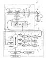
図1に示すように、本実施形態に係るHMD1は、画像信号に応じた強度のレーザ光を画像光として出射するコントロールユニット2と、コントロールユニット2から出射された画像光を伝送する光ファイバケーブル50(後述)を備えた伝送ケーブル部3と、頭部に装着することで、伝送された画像光を走査して使用者の眼に投射し、使用者に対して画像を表示するための頭部装着具4とを備えている。なお、伝送ケーブル部3は、後述の投影部10に備えられた水平走査部80及び垂直走査部90と後述の光源ユニット11との間で同期をとるための水平駆動信号61、垂直駆動信号62を伝送する駆動信号伝送用ケーブルも有している。 As shown in FIG. 1, the
コントロールユニット2は、内蔵したコンテンツ記憶部に記憶されたコンテンツ情報に基づいて画像信号を形成し、この画像信号に応じた強度のレーザ光を画像光として伝送ケーブル部3へ出射する。また、コントロールユニット2には、外部入出力端子5が形成されており、外部からの画像信号を入力したり、図示しないパーソナルコンピュータ等との間で画像信号を形成するためのコンテンツ情報などの送受信を可能としている。なお、ここでコンテンツ情報とは、文字を表示させるためのデータ、画像を表示させるためのデータ及び動画を表示させるためのデータのうちの少なくとも1つのデータで構成されるものであり、例えば、パソコン等で使用される文書ファイルや画像ファイル、動画ファイル等である。 The control unit 2 forms an image signal based on the content information stored in the built-in content storage unit, and emits laser light having an intensity corresponding to the image signal to the
頭部装着具4は、伝送ケーブル部3により伝送されてきた画像光を、使用者が表示画像として認識可能とするために走査する投影部10と、この投影部10を支持する眼鏡型フレーム6とで構成している。本実施形態に係るHMD1は、この眼鏡型フレーム6に特徴を有するものであり、具体的な構成については後に詳述する。 The
投影部10は、各色(R,G,B)毎に強度変調された画像光を2次元方向に走査した画像光を使用者の眼Yに入射させ、使用者の眼Yの網膜上で画像光を2次元方向に走査することにより、使用者に画像情報に応じた画像を視認させる網膜走査ディスプレイを構成している。 The
この投影部10には、使用者の眼Yと対向する位置にハーフミラー9が設けられている。そのため、外光Laはハーフミラー9を透過して使用者の眼Yに入射され、投影部10から出射される画像光Lbはハーフミラー9で反射して使用者の眼Yに入射されて、使用者は外光Laによる外景に画像光による画像を重ねて視認することができる。 The
このようにHMD1は、外光を透過しつつ、画像光を使用者の眼Yに投射するシースルー型のHMDとしている。なお、本実施形態ではシースルー型のHMDについて説明するが、必ずしもシースルー型である必要はなく、又光走査型である必要もない。 As described above, the
〔HMDの電気的構成及び光学的構成〕
次に、図2を参照しながら、HMD1の電気的構成及び光学的構成について説明する。図2は、電気的構成及び光学的構成を示した説明図である。[Electrical configuration and optical configuration of HMD]
Next, the electrical configuration and optical configuration of the
図2に示すように、HMD1は、コントロールユニット2と、ハーフミラー9と、投影部10とを備え、コントロールユニット2内には、HMD1全体の動作を統括制御する制御部30と、この制御部30から供給される画像信号Sから画像情報を画素単位で読み出し、読み出した画素単位の画像情報に基づいてR(赤色),G(緑色),B(青色)の各色毎に強度変調されたレーザ光を生成して出射する光源ユニット11が設けられている。なお、光源ユニット11をコントロールユニット2内に設けるのではなく、投影部10内に設けるようにしてもよい。 As shown in FIG. 2, the
(光源ユニット11)
光源ユニット11には、画像を合成するための要素となる信号等を発生する画像信号供給回路13が設けられている。外部入出力端子5を介して外部接続した図示しない機器類から供給される画像データや、比較的大容量の記憶領域を有するコンテンツ記憶部14に予め記憶されたコンテンツ情報に基づく画像データが制御部30に入力されると、制御部30はその画像データに基づいて画像信号Sを生成して画像信号供給回路13に送る。画像信号供給回路13は、画像信号Sに基づいて、表示画像を形成するための要素となる各信号を画素単位で生成する。すなわち、画像信号供給回路13からは、R(赤色)画像信号60r,G(緑色)画像信号60g,B(青色)画像信号60bが生成されて出力される。また、画像信号供給回路13は、水平走査部80で使用される水平駆動信号61と、垂直走査部90で使用される垂直駆動信号62とをそれぞれ出力する。なお、コンテンツ記憶部14は、例えば、ハードディスクの如き磁気的記憶媒体や、CD−Rの如き光学的記憶媒体や、フラッシュメモリ等とすることができる。(Light source unit 11)
The light source unit 11 is provided with an image
また、光源ユニット11には、画像信号供給回路13から画素単位で出力されるR画像信号60r、G画像信号60g、B画像信号60bの各画像信号60r,60g,60bをもとに、それぞれ強度変調されたレーザ光(「光束」とも呼ぶ。)を出射するように、Rレーザ63,Gレーザ64,Bレーザ65をそれぞれ駆動するためのRレーザドライバ66,Gレーザドライバ67,Bレーザドライバ68が設けられている。各レーザ63,64,65は、例えば、半導体レーザや高調波発生機構付き固体レーザとして構成することが可能である。なお、半導体レーザを用いる場合は駆動電流を直接変調して、レーザ光の強度変調を行うことができるが、固体レーザを用いる場合は、各レーザそれぞれに外部変調器を備えてレーザ光の強度変調を行う必要がある。 The light source unit 11 has an intensity based on the image signals 60r, 60g, and 60b of the
さらに、光源ユニット11は、各レーザ63,64,65より出射されたレーザ光を平行光にコリメートするように設けられたコリメート光学系71,72,73と、このコリメートされたレーザ光を合波するためのダイクロイックミラー74,75,76と、合波されたレーザ光を光ファイバケーブル50に導く結合光学系77とが設けられている。 Further, the light source unit 11 combines the collimated laser light and collimated
従って、各レーザ63,64,65から出射したレーザ光は、コリメート光学系71,72,73によってそれぞれ平行化された後に、ダイクロイックミラー74,75,76に入射される。その後、これらのダイクロイックミラー74,75,76により、各レーザ光が波長に関して選択的に反射・透過される。そして、これら3つのダイクロイックミラー74,75,76にそれぞれ入射した3原色のレーザ光は、波長選択的に反射または透過して結合光学系77に達し、集光されて光ファイバケーブル50へ出力される。なお、光ファイバケーブル50は、図1にて示した伝送ケーブル部3内に収容されている。 Therefore, the laser beams emitted from the
(投影部10)
光源ユニット11と使用者の眼Yとの間に位置する投影部10には、光源ユニット11で生成され、光ファイバケーブル50を介して出射されるレーザ光を平行光化するコリメート光学系79と、このコリメート光学系79で平行光化されたレーザ光を画像表示のために水平方向に往復走査する水平走査部80と、水平走査部80で水平方向に走査されたレーザ光を垂直方向に走査する垂直走査部90と、水平走査部80と垂直走査部90との間に設けられた第1リレー光学系85と、このように水平方向と垂直方向に走査されたレーザ光を瞳孔101aへ出射するための第2リレー光学系95とが設けられている。(Projector 10)
The
水平走査部80及び垂直走査部90は、光ファイバケーブル50から入射されたレーザ光を画像として使用者の網膜101bに投影可能な状態にするために、水平方向と垂直方向に走査して走査光束とする光学系である。以下の説明において、この水平走査部80及び垂直走査部90を総称して走査部ともいう。 The
水平走査部80は、レーザ光を水平方向に走査するため偏向面を有する共振型の偏向素子81と、この偏向素子81を共振させて偏向素子81の偏向面を揺動させる駆動信号を水平駆動信号61に基づいて発生する水平走査駆動回路82を備えている。 The
一方、垂直走査部90は、レーザ光を垂直方向に走査するため偏向面を有する共振型の偏向素子91と、この偏向素子91の偏向面を共振状態で揺動させる駆動信号を垂直駆動信号62に基づいて発生する垂直走査制御回路92とを備え、表示すべき画像の1フレームごとに、画像を形成するためのレーザ光を最初の水平走査線から最後の水平走査線に向かって垂直に走査する。ここで「水平走査線」とは、水平走査部80による水平方向への1走査を意味する。 On the other hand, the
また、水平走査部80と垂直走査部90との間でレーザ光を中継する第1リレー光学系85は、偏向素子81の偏向面によって水平方向に走査されたレーザ光を偏向素子91の偏向面に収束させる。そして、このレーザ光が偏向素子91の偏向面によって垂直方向に走査されて画像光Lbとして、正の屈折力を持つ2つのレンズ95a,95bが直列配置された第2リレー光学系95を介して、眼Yの前方に位置させたハーフミラー9で反射されて使用者の瞳孔101aに入射し、網膜101b上に画像信号Sに応じた表示画像が投影される。これにより、使用者はこの画像光Lbを、表示画像として認識することとなる。 Further, the first relay
また、第2リレー光学系95においては、レンズ95aによって、それぞれのレーザ光がそのレーザ光の中心線を相互に略平行にされ、かつそれぞれ収束レーザ光に変換される。そして、レンズ95bによってそれぞれほぼ平行なレーザ光となると共に、これらのレーザ光の中心線が使用者の瞳孔101aに収束するように変換される。このレンズ95bは、走査部で走査された画像光Lb(レーザ光)を使用者の眼Yに入射させて、使用者の網膜101b上に画像信号Sに応じた画像を投影する接眼光学系として機能する。 Further, in the second relay
次に、頭部装着具4を構成する眼鏡型フレーム6の具体的な構成について、図3〜図9を用いながら説明する。 Next, a specific configuration of the eyeglass-
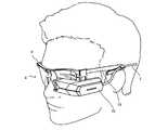
〔頭部装着具4の特徴〕
まず、頭部装着具4の特徴点について、図3を用いて説明する。図3は頭部装着具4を装着した使用者を示す説明図である。[Features of the head mounting tool 4]
First, feature points of the
図3に示すように、頭部装着具4は、視力矯正用の一般的な眼鏡の装着と同様に装着することで、投影部10を容易に眼前に配置できるよう構成している。 As shown in FIG. 3, the
また、特徴的には、眼鏡型フレーム6のテンプル16の撓み量を増やすべく、中途部がZ型に形成されており、使用者の頭部形状の違いに応じて形状が変化し、さまざまな使用者の頭部に可及的にフィットさせることができるよう構成している。すなわち、撓みを生起するZ型のサスペンション構造を備えている。 Also, characteristically, in order to increase the amount of deflection of the
また、投影部10より延出する伝送ケーブル部3を、眼鏡型フレーム6のテンプル16に取付可能としており、使用者が頭部装着具4を装着した際に、伝送ケーブル部3による煩わしさを感じさせることがない。 Further, the
しかも、テンプル16のZ型の形状は、看者にスタイリッシュな印象を与える優れた意匠となっている。 Moreover, the Z shape of the
〔頭部装着具4の構成概要〕
次に、本実施形態に係るHMD1の頭部装着具4の構成概要について、図4を用いながら説明する。図4は頭部装着具4の外観を示した斜視図である。[Configuration outline of head mounting tool 4]
Next, an outline of the configuration of the
頭部装着具4の眼鏡型フレーム6は、図4に示すように、使用時に、使用者の眼前に位置するフロント部15と、同フロント部15の左右両端より後方へ伸延するテンプル16,16とで、外観視略眼鏡型に構成されている(図3参照)。 As shown in FIG. 4, the eyeglass-
フロント部15は、左右方向へ架け渡されたフロントフレーム17と、同フロントフレーム17の両端部近傍に設けられているバイザー挟持部18,18に取り付られたバイザー部19とを備えている。 The
フロントフレーム17は、視力矯正用の一般的な眼鏡に比して前後方向に厚く、左右のテンプル16,16を左右方向に大きく開いた場合でも、撓みが少ないように形成している。なお、このフロントフレーム17を構成する素材としては、撓みの少ない金属や樹脂が好適である。 The
また、フロントフレーム17の左右端部は後方へ屈曲伸延して略L字状のヨロイ部21を形成しており、その先端部には、テンプル16を揺動自在に連結する支軸としての丁番部22がそれぞれ設けられている。また、フロントフレーム17の略中央部には、フロント部15を使用者の鼻部で支えるための鼻あて部20が設けられている。 Further, the left and right end portions of the
図4中、右側のテンプル16には、投影部10が配設されており、同投影部10より伸延する伝送ケーブル部3の中途部が、テンプル16の中途にケーブル保持部23によって固定されるよう構成している。 In FIG. 4, the
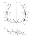
〔テンプル16の具体的な構成〕
図5(a)は眼鏡型フレーム6の平面視における外観図であり、図5(b)は眼鏡型フレーム6の側面視における外観図である。なお、以下の説明において、「内方」とはテンプル16,16を開いた状態(図5(a)に示す状態)で、それぞれのテンプル16,16よりも中心線X寄りの方向を意味し、「外方」とは中心線Xから離れる方向を意味する。[Specific structure of temple 16]
5A is an external view of the spectacles-
図5(a)に示すように、テンプル16,16は、中心線Xに対して左右対称に取り付けられている。また、テンプル16,16は、それぞれ中途部に平面視略Z字状の弾性屈曲部24を備えており、使用者が眼鏡型フレーム6を装着した際に、この弾性屈曲部24が撓んでテンプル16,16が頭部形状に合わせてフィットするよう構成されている。なお、このテンプル16,16を構成する素材としては、フロントフレーム17に比して撓みの大きい金属や樹脂が好適である。 As illustrated in FIG. 5A, the
具体的には、左右それぞれのテンプル16は、図5(a)及び(b)に示すように、ヘアピン状に中途で鋭角に折り返して形成された平面視略V字形状をなすテンプル前片27と、このテンプル前片27に連結されて使用者の側頭部(耳の上部付け根)から後頭部にかけてフィットするよう湾曲させて形成したテンプル後片28とで構成している。 Specifically, as shown in FIGS. 5A and 5B, each of the left and
平面視略V字状に形成されたテンプル前片27は、フロントフレーム17側をなす長片25と、この長片25とでV字形状をなす短片26とからなり、長片25の前端部近傍は、丁番部22を介してフロント部15に揺動自在に連結されている。また、図5(b)に示すように、当該長片25はやや外方へ湾曲しながら後方へ伸延するとともに、後端部には下方に略直角に折曲して短片26と連続する折曲部29が形成されている。 The
長片25と一体的に同一板材で形成された短片26は、折曲部29の下端部から前方へ伸延している。具体的には、短片26は、平面視において、折曲部29から前方へ内方寄りに伸延させつつ、先端部を外方へ角度αで折曲して形成し(図5(a)参照)、内方から外方へ向かう力によって撓みやすい構造としている。なお角度αは約155〜165°としている。また、短片26は、側面視において、長片25の折曲部29下端から前方へ向け、やや斜め下方へ伸延させており(図5(b)参照)、その先端部、すなわち、前述の角度αをもって折曲させた部分にテンプル後片28をろう付にて接合している。なお、このテンプル後片28は、後部をやや下方へ向けて内方よりに伸延させた形状としており、装着した際の皮膚との接触を良好とするために略全体を樹脂で被覆している。 The
以上説明してきた構成とすることで、テンプル前片27には、図5(a)にも示すように、長片25の後方側一部と短片26とにより、後端部に平面視略V字状の第1V字状屈曲部31及び第2V字状屈曲部32が形成され、かかる第1V字状屈曲部31及び第2V字状屈曲部32により、平面視及び側面視において略Z字状の弾性屈曲部24が構成される。 With the above-described configuration, the
換言すれば、弾性屈曲部24は、前記テンプル16の先端側から順に形成した第1V字状屈曲部31と第2V字状屈曲部32とにより形成して平面視Z字状としている。 In other words, the elastic
このように、テンプル16の中途に、平面視Z字状の弾性屈曲部24を設けたため、視力矯正用の眼鏡などに見られる平面視直線状で側面視J字状の単純なテンプルに比して、撓み量を更に増やすことができ、異なった顔幅や頭部形状に対し柔軟に対応させることができる。 As described above, since the elastic
また、平面視直線状の単純なテンプルは、頭部の最大幅の部分に、内方へ向かう締め付け力が一点集中しがちであるが、Z字状の弾性屈曲部を有するテンプル16によれば、力が分散されて、使用者が過剰な締め付け感を感じてしまうことを防止できる。 In addition, a simple temple in a straight line in plan view tends to concentrate a single inward tightening force in the maximum width portion of the head, but according to the
例えば、使用者が装着する前の状態では、図6(a)に示すように、短片26が自由状態となっているが、使用者が装着すると使用者の顔幅に応じて弾性屈曲部24は外方へ付勢されるとともに、図6(b)に示すように、テンプル後片28の後端部近傍は内方へ移動し、使用者の後頭部近傍を穏やかに包み込んでフィットすることとなる。 For example, in a state before the user wears, the
また、さらに頭部鉢周りの大きい人や顔幅の広い人が装着した場合、弾性屈曲部24はさらに外方へ付勢されるとともに、図6(c)に示すように、テンプル後片28の後端部近傍はさらに内方へ移動し、使用者の後頭部近傍をよりしっかりと包み込んでフィットすることとなる。 Further, when a person around the head bowl or a person with a wide face is worn, the
しかもこの際、使用者の頭部にかかる力は、一点に集中せず、テンプル後片28略全体から包み込むように付与されることとなるため、使用者は、過度な締め付け感を感じることがない。 In addition, at this time, the force applied to the user's head is not concentrated on a single point, but is applied so as to wrap from substantially the entire temple
また、本実施形態に係る眼鏡型フレーム6では、側面視Z字状に構成しているために、弾性屈曲部24を備えていない単純なテンプルに対して、テンプル16,16の前方側と後方側とで上下方向の幅を大きくとることができる。 Further, since the
すなわち、HMD1では投影部10の配置を使用者の眼前に配置することになるため、フロント部15のフロントフレーム17が邪魔にならないように、フロントフレーム17を通常の眼鏡よりも上方に配置する必要があり、フロントフレーム17の高さ位置が使用者の耳よりもかなり上方にせざるを得ない。そのため、一般的な単純な直線状のテンプルでは上下方向の幅を広くせざるを得ず、重量的な課題が出てくる。しかし、本実施形態に係る眼鏡型フレーム6では、テンプル16,16を側面視Z字状に構成しているために、テンプル16,16の上下方向の厚みを厚くする必要がなく、軽量化を図ることができる。 That is, in the
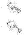
〔眼鏡型フレーム6への投影部10の取付〕
テンプル16には、それぞれ長片25の前端部を、丁番部22を基端としてさらに前方に延出させて突出させた突出部33が形成されており、図3及び図4にも示したように、投影部10を眼鏡型フレーム6のうち前記弾性屈曲部24よりも前方に取り付け可能としている。[Attachment of
Each of the
この投影部10の取り付け状態について説明すると、図7(a)に示すように、突出部33には、その先端部近傍に取付け凹部39が形成されている。 The attachment state of the
一方、投影部10は、図7(b)に示すように、伝送ケーブル部3が延出する基端部45と、使用者の眼前に望ませるハーフミラー9を備えた先端部34とで平面視略L字状に形成しており、基端部45の内側面35には、眼鏡型フレーム6と連結させるための取付部材36を備えている。 On the other hand, as shown in FIG. 7 (b), the
この取付部材36は、投影部回動軸37を介して投影部10を回動自在に連結する一方、その上部に突出部33の断面形状と略同型の取付挿入孔38が形成されている。 The
また、取付挿入孔38内には、前述の取付け凹部39と嵌合する取付凸部(図示せず)が形成されている。 Further, in the
そして、取付挿入孔38に突出部33を挿入することで、眼鏡型フレーム6に投影部10を取付け可能としている。また、この際、前述の取付け凹部39と取付凸部とが嵌合して、挿入後の位置決めを容易としている。 And the
また、ヨロイ部21には、その側面部、すなわち、テンプル16を左右方向に開いた際に突出部33が対向する部位を一部肉薄状としてヨロイ凹部40が形成されている。このヨロイ凹部40は、取付挿入孔38に突出部33を挿入して眼鏡型フレーム6に投影部10を取付けてテンプル16を左右方向に開いた際に、取付挿入孔38周囲の肉厚を逃がすための部位である。 Further, the
また、ヨロイ凹部40の先端には、フロントフレーム17を外方へ膨出させて形成した脱落防止凸部41が備えられている。この脱落防止凸部41は、テンプル16を左右方向に開いた状態において、投影部10が前方に移動しないように規制し、投影部10が突出部33から抜け落ちるのを防止するためのものである。 Further, a drop-off preventing convex portion 41 formed by bulging the
〔第1V字状屈曲部31〕
本実施形態に係るHMD1の眼鏡型フレーム6では、図3及び図4にも示したように第1V字状屈曲部31にケーブル保持部23を取付け可能としており、伝送ケーブル部3を眼鏡型フレーム6に保持できるように構成している。[First V-shaped bent portion 31]
In the glasses-
具体的には、図8(a)に示すように、伝送ケーブル部3を挿通するケーブル保持部23は、一側面に平面視略L字状の係止片42を備えており、この係止片42の先端には、係止凸部43が形成されている。 Specifically, as shown in FIG. 8A, the
一方、第1V字状屈曲部31の内側面には、図8(b)に示すように、前記係止凸部43と係合する係止凹部44が形成されている。 On the other hand, on the inner side surface of the first V-shaped
そして、長片25と短片26とにより形成された間隙に、ケーブル保持部23の係止片42を沿わせて後方へスライドさせることにより、伝送ケーブル部3をケーブル保持部23により第1V字状屈曲部31に取付できるようにしている。 And the
従って、できるだけ使用者の耳に近い位置でありながら、耳には接触することなく、テンプル16に伝送ケーブル部3を装着し固定することができる。 Therefore, the
上述してきたように構成することで、図9(a)に示すように、投影部10とケーブル保持部23とをテンプル16に装着することができることとなる。 With the configuration as described above, the
また、図9(a)を見ても分かるように、投影部10は、テンプル16に形成した突出部33に装着されているため、テンプル16の揺動に追従し、使用者の眼前と側方との間で移動する。 Further, as can be seen from FIG. 9A, the
これにより、テンプル16を左右方向に開いた状態から閉じた状態に動かした場合でも、投影部10からケーブル保持部23までの距離は変化せず、投影部10とケーブル保持部23との間の伝送ケーブル部3に過剰な張力が働くことがないため、投影部10と伝送ケーブル部3との接続部分に負荷が加わるのを防止することができる。 Thereby, even when the
すなわち、投影部10とケーブル保持部23との両者ともテンプル16に配設されるため、投影部10をフロントフレーム17に固定し、ケーブル保持部23をテンプル16に固定した場合に比して、テンプル16の開閉時に伝送ケーブル部3に働く負荷を軽減することができる。 That is, since both the
また、図9(b)に示すように、投影部10を突出部33から取り外す場合、投影部10を図中白抜きの矢印方向へ移動させることによって、ケーブル保持部23もまた第1V字状屈曲部31の間隙から外れることとなる。 Further, as shown in FIG. 9B, when the
したがって、投影部10を容易に取り外すことができ、しかも、伝送ケーブル部3に過剰な張力が加わるのを防止することができる。 Therefore, it is possible to easily remove the
最後に、上述した各実施の形態の説明は本発明の一例であり、本発明は上述の実施の形態に限定されることはない。このため、上述した各実施の形態以外であっても、本発明に係る技術的思想を逸脱しない範囲であれば、設計等に応じて種々の変更が可能であることは勿論である。 Finally, the description of each embodiment described above is an example of the present invention, and the present invention is not limited to the above-described embodiment. For this reason, it is a matter of course that various modifications can be made in accordance with the design and the like as long as they do not depart from the technical idea according to the present invention other than the embodiments described above.
例えば、眼鏡型フレーム6の説明において、使用した図面中投影部10は、右側の突出部33取り付けたが、左側の突出部33に取り付けても良く、左右両方の突出部33,33に取り付けるようにしても良い。 For example, in the description of the eyeglass-
また、ケーブル保持部23は、第1V字状屈曲部31に取り付けることとしたが、短片26の弾性を損なうことがなければ、同様または類似の構成により、漸次狭隘となる形状を生かして第2V字状屈曲部32にケーブル保持部23を取付可能に構成しても良い。 In addition, the
また、投影部10は、テンプル16先端の突出部33に配設することとしたが、これに限定されるものではなく、フロントフレーム17に配設するようにしても良い。 Further, the
この際、投影部10のフロントフレーム17への取り付け、取り外しは、ケーブル保持部23の第1V字状屈曲部31への取り付け、取り外しの方向と一致させることにより、投影部10の取り外しに追従して、ケーブル保持部23の取り外しを同時に行わせることができる。 At this time, the
また、長片25と短片26とは、テンプル前片27として一体的に形成したが、これに限定されるものではなく、例えば、長片25と、短片26と、テンプル後片28との3つの部材により弾性屈曲部24を形成し、テンプル16を構成するようにしても良い。 Moreover, although the
また、眼鏡型フレーム6は、頭部装着具4を構成する一部として例示したが、非常に洗練された意匠を備えており、投影部10や伝送ケーブル部3を取り外し、眼鏡型フレーム6のみで普段使いの眼鏡として使用しても良い。 Moreover, although the
すなわち、眼鏡型フレーム6のバイザー部19をレンズに変更することにより、視力矯正用の眼鏡として使用しても良く、また、サングラスとして使用しても良い。 That is, by changing the
上述してきたように、本実施形態に係るHMD1によれば、以下の効果が期待できる。 As described above, according to the
(1)画像情報に応じた画像を使用者の眼の網膜101bに投影する投影部10を眼鏡型フレーム6に取付けたヘッドマウントディスプレイにおいて、眼鏡型フレーム6の左右テンプル16,16の中途に平面視Z字状の弾性屈曲部24を設け、投影部10を眼鏡型フレーム6のうち弾性屈曲部24よりも前方に配置したため、不特定多数の人が装着する場合であっても、それぞれの使用者の頭部に可及的にフィットさせることのできるヘッドマウントディスプレイを提供することができる。(1) In a head mounted display in which a
(2)また、弾性屈曲部24は側面視においてもZ字状に形成したため、テンプル後片28→弾性屈曲部24→テンプル前片27と階段状に形成し、投影部10の取付位置を、耳に対して上方とすることができるため、テンプル16,16を上下方向に厚くすることなく、使用者の眼球に対して適正に画像を投影することができる。また、使用者が装着するに際し、良好な意匠性を備えることができる。(2) Further, since the
(3)また、弾性屈曲部24は、テンプル16の先端側から順に形成した第1V字状屈曲部31と第2V字状屈曲部32とにより形成して平面視Z字状とし、当該第1V字状屈曲部31にケーブル保持部23を取付け可能としたため、使用者に対し、垂れ下がった伝送ケーブル部3により煩わしさを感じさせることがなく、また、伝送ケーブル部3をテンプル16に沿って整然と取り付けることができる。(3) The elastic
(4)また、眼鏡型フレーム6は、左右テンプル16,16と、当該左右テンプル16,16を支軸を介して連結したフロントフレーム17とを備え、前記左右テンプル16,16に前記支軸を基端として前方に突出する突出部33,33を形成し、当該突出部33,33に投影部10に形成された取付け凹部39を嵌合可能としたため、投影部10は、テンプル16の揺動に追従して使用者の眼前と側方との間で移動することとなり、テンプル16を開いた状態から閉じた状態に動かした場合でも、投影部10とケーブル保持部23との間の伝送ケーブル部3に過剰な張力が働くことがなく、投影部10と伝送ケーブル部3との接続部分に負荷が加わるのを防止することができる。(4) The eyeglass-
(5)また、眼鏡型フレーム6は、左右テンプル16,16と、当該左右テンプル16,16を支軸を介して連結したフロントフレーム17とを備え、投影部10をフロントフレーム17に配置したため、左右テンプル16,16を開いた状態であっても、投影部10を取り外すことができ、しかも、投影部10を前方へ引いて取り外す動きに追従して、第1V字状屈曲部31に配設したケーブル保持部23を同時に取り外すことができる。(5) The eyeglass-
1 ヘッドマウントディスプレイ
3 伝送ケーブル部
4 頭部装着具
6 眼鏡型フレーム
10 投影部
15 フロント部
16 テンプル
17 フロントフレーム
22 丁番部
23 ケーブル保持部
24 弾性屈曲部
25 長片
26 短片
27 テンプル前片
28 テンプル後片
31 第1V字状屈曲部
32 第2V字状屈曲部
33 突出部
36 取付部材
37 投影部回動軸
38 取付挿入孔
39 取付け凹部DESCRIPTION OF
Claims (4)
Translated fromJapanese前記眼鏡型フレームの左右テンプルの中途に平面視Z字状の弾性屈曲部を設け、前記投影部を前記眼鏡型フレームのうち前記弾性屈曲部よりも前方に配置すると共に、前記弾性屈曲部は側面視においてもZ字状に形成したことを特徴とするヘッドマウントディスプレイ。In a head-mounted display in which a projection unit that projects an image according to image information onto a retina of a user's eye is attached to a spectacle-shaped frame,
An elastic bent portion having a Z-shape in plan view is provided in the middle of the left and right temples of the eyeglass-shaped frame, the projection portion is disposedin front of the elastic bent portion of the eyeglass-shaped frame, and the elastic bent portion is a side surface. A head-mounted display that isformed in aZ-shape when viewed .
前記弾性屈曲部は、前記テンプルの先端側から順に形成した第1V字状屈曲部と第2V字状屈曲部とにより形成して平面視Z字状とし、当該第1V字状屈曲部に前記ケーブル保持部を取付け可能としたことを特徴とする請求項1に記載のヘッドマウントディスプレイ。A cable holding part for holding the cable extended from the projection part in the glasses-type frame;
The elastic bent portion is formed by a first V-shaped bent portion and a second V-shaped bent portion formed in order from the distal end side of the temple to form a Z shape in a plan view, and the cable is connected to the first V-shaped bent portion. The head mounted display according to claim1, wherein the holding portion can be attached.
前記左右テンプルに前記支軸を基端として前方に突出する突出部を形成し、当該突出部に前記投影部に形成された取付け凹部を嵌合可能としたことを特徴とする請求項1又は2に記載のヘッドマウントディスプレイ。The glasses-type frame includes the left and right temples and a front frame in which the left and right temples are connected via a support shaft,
Wherein said support shaft in the left and right temples to form a protruding portion protruding forward as proximal, claim 1or 2, characterized in that a mounting recess formed in the projecting portion on the projecting portion and can be fitted The head mounted display as described in.
前記投影部を前記フロントフレームに配置したことを特徴とする請求項1又は2に記載のヘッドマウントディスプレイ。The glasses-type frame includes the left and right temples and a front frame in which the left and right temples are connected via a support shaft,
Head-mounted display according to claim 1or 2, characterized in that a said projection unit on the front frame.
Priority Applications (3)
| Application Number | Priority Date | Filing Date | Title |
|---|---|---|---|
| JP2009083173AJP5245981B2 (en) | 2009-03-30 | 2009-03-30 | Head mounted display |
| US12/659,820US8123352B2 (en) | 2009-03-30 | 2010-03-23 | Head mounted display |
| EP10250625AEP2239614A3 (en) | 2009-03-30 | 2010-03-29 | Head mounted display |
Applications Claiming Priority (1)
| Application Number | Priority Date | Filing Date | Title |
|---|---|---|---|
| JP2009083173AJP5245981B2 (en) | 2009-03-30 | 2009-03-30 | Head mounted display |
Publications (2)
| Publication Number | Publication Date |
|---|---|
| JP2010239282A JP2010239282A (en) | 2010-10-21 |
| JP5245981B2true JP5245981B2 (en) | 2013-07-24 |
Family
ID=42227738
Family Applications (1)
| Application Number | Title | Priority Date | Filing Date |
|---|---|---|---|
| JP2009083173AExpired - Fee RelatedJP5245981B2 (en) | 2009-03-30 | 2009-03-30 | Head mounted display |
Country Status (3)
| Country | Link |
|---|---|
| US (1) | US8123352B2 (en) |
| EP (1) | EP2239614A3 (en) |
| JP (1) | JP5245981B2 (en) |
Cited By (1)
| Publication number | Priority date | Publication date | Assignee | Title |
|---|---|---|---|---|
| US10268042B2 (en) | 2016-08-19 | 2019-04-23 | Seiko Epson Corporation | Head-mounted image display device |
Families Citing this family (51)
| Publication number | Priority date | Publication date | Assignee | Title |
|---|---|---|---|---|
| US8825468B2 (en)* | 2007-07-31 | 2014-09-02 | Kopin Corporation | Mobile wireless display providing speech to speech translation and avatar simulating human attributes |
| WO2009120984A1 (en) | 2008-03-28 | 2009-10-01 | Kopin Corporation | Handheld wireless display device having high-resolution display suitable for use as a mobile internet device |
| US8665177B2 (en)* | 2010-02-05 | 2014-03-04 | Kopin Corporation | Touch sensor for controlling eyewear |
| US8706170B2 (en) | 2010-09-20 | 2014-04-22 | Kopin Corporation | Miniature communications gateway for head mounted display |
| US8736516B2 (en) | 2010-09-20 | 2014-05-27 | Kopin Corporation | Bluetooth or other wireless interface with power management for head mounted display |
| US9377862B2 (en) | 2010-09-20 | 2016-06-28 | Kopin Corporation | Searchlight navigation using headtracker to reveal hidden or extra document data |
| US10013976B2 (en) | 2010-09-20 | 2018-07-03 | Kopin Corporation | Context sensitive overlays in voice controlled headset computer displays |
| US9316827B2 (en) | 2010-09-20 | 2016-04-19 | Kopin Corporation | LifeBoard—series of home pages for head mounted displays (HMD) that respond to head tracking |
| JP5477310B2 (en) | 2011-02-24 | 2014-04-23 | ブラザー工業株式会社 | Head-mounted image display device |
| CN109116985A (en) | 2011-05-10 | 2019-01-01 | 寇平公司 | The method that control information is shown |
| EP2728399A4 (en)* | 2011-06-30 | 2015-01-28 | Planet Vision60 Co Ltd | Temple for eyeglass frame, and method for producing temple |
| JP2013046143A (en)* | 2011-08-23 | 2013-03-04 | Brother Ind Ltd | Head mounted apparatus and mounting frame |
| JP5363555B2 (en)* | 2011-12-01 | 2013-12-11 | オリンパス株式会社 | Wearable device support member and head-mounted wearable device |
| US8929954B2 (en) | 2012-04-25 | 2015-01-06 | Kopin Corporation | Headset computer (HSC) as auxiliary display with ASR and HT input |
| US9442290B2 (en) | 2012-05-10 | 2016-09-13 | Kopin Corporation | Headset computer operation using vehicle sensor feedback for remote control vehicle |
| US9378028B2 (en) | 2012-05-31 | 2016-06-28 | Kopin Corporation | Headset computer (HSC) with docking station and dual personality |
| US9720231B2 (en) | 2012-09-26 | 2017-08-01 | Dolby Laboratories Licensing Corporation | Display, imaging system and controller for eyewear display device |
| USD708663S1 (en)* | 2012-10-16 | 2014-07-08 | Wen-Tse HUANG | Temple sleeve for eyeglasses |
| USD713406S1 (en) | 2012-11-30 | 2014-09-16 | Kopin Corporation | Headset computer with reversible display |
| CN103852903A (en)* | 2012-12-05 | 2014-06-11 | 能富企业有限公司 | Eyeglasses |
| US9160064B2 (en) | 2012-12-28 | 2015-10-13 | Kopin Corporation | Spatially diverse antennas for a headset computer |
| US9134793B2 (en) | 2013-01-04 | 2015-09-15 | Kopin Corporation | Headset computer with head tracking input used for inertial control |
| US9298011B2 (en)* | 2013-05-21 | 2016-03-29 | Kopin Corporation | Wearable electronic eyewear display |
| US20140368787A1 (en)* | 2013-06-14 | 2014-12-18 | Marchon Eyewear, Inc. | Eyewear configured to support computing device(s) |
| US8958158B1 (en) | 2013-12-03 | 2015-02-17 | Google Inc. | On-head detection for head-mounted display |
| US9294739B1 (en)* | 2014-06-06 | 2016-03-22 | Google Inc. | Magnetically coupled waterproof hinge with integrated multi-stage button and state detection |
| US9635222B2 (en) | 2014-08-03 | 2017-04-25 | PogoTec, Inc. | Wearable camera systems and apparatus for aligning an eyewear camera |
| CA2956795C (en) | 2014-08-03 | 2020-06-30 | PogoTec, Inc. | Wearable camera systems and apparatus and method for attaching camera systems or other electronic devices to wearable articles |
| CN105373211B (en)* | 2014-08-15 | 2021-07-30 | 谢爱国 | Wearable smart machine |
| JP6536019B2 (en)* | 2014-11-21 | 2019-07-03 | セイコーエプソン株式会社 | Controller and image display system |
| CA2972064A1 (en) | 2014-12-23 | 2016-06-30 | PogoTec, Inc. | Wireless camera system and methods |
| WO2016143685A1 (en)* | 2015-03-11 | 2016-09-15 | コニカミノルタ株式会社 | Head-mounted display |
| EP3308216B1 (en)* | 2015-06-10 | 2021-04-21 | Pogotec, Inc. | Eyewear with magnetic track for electronic wearable device |
| US10481417B2 (en) | 2015-06-10 | 2019-11-19 | PogoTec, Inc. | Magnetic attachment mechanism for electronic wearable device |
| KR20170016192A (en)* | 2015-08-03 | 2017-02-13 | 엘지전자 주식회사 | Wareable device |
| TW201729610A (en) | 2015-10-29 | 2017-08-16 | 帕戈技術股份有限公司 | Hearing aid adapted for wireless power reception |
| JP1564085S (en)* | 2016-02-19 | 2016-11-28 | ||
| US11558538B2 (en) | 2016-03-18 | 2023-01-17 | Opkix, Inc. | Portable camera system |
| JP6551278B2 (en)* | 2016-03-25 | 2019-07-31 | ブラザー工業株式会社 | Head mounted display |
| JP6829375B2 (en)* | 2016-09-28 | 2021-02-10 | ミツミ電機株式会社 | Optical scanning head-mounted display and retinal scanning head-mounted display |
| EP3539285A4 (en) | 2016-11-08 | 2020-09-02 | Pogotec, Inc. | A smart case for electronic wearable device |
| CN108108011B (en)* | 2016-11-24 | 2025-01-10 | 京东方科技集团股份有限公司 | A virtual reality all-in-one machine |
| CN107174195B (en)* | 2017-05-16 | 2019-05-14 | 上海展志光学仪器有限公司 | Visual chart projecting method and VR spectacle vision table projector based on VR technology |
| JP6968689B2 (en)* | 2017-12-27 | 2021-11-17 | Dynabook株式会社 | Electronic devices, wearable devices and display control methods |
| JP2019129484A (en)* | 2018-01-26 | 2019-08-01 | セイコーエプソン株式会社 | Virtual image display device and nose pad therefor |
| KR20200015278A (en)* | 2018-08-03 | 2020-02-12 | 삼성전자주식회사 | Optical lens assembly and electronic apparatus having the same |
| US11300857B2 (en) | 2018-11-13 | 2022-04-12 | Opkix, Inc. | Wearable mounts for portable camera |
| WO2020235816A1 (en) | 2019-05-21 | 2020-11-26 | Samsung Electronics Co., Ltd. | Glasses-type display apparatus |
| US11733526B1 (en) | 2020-09-24 | 2023-08-22 | Apple Inc. | Head-mountable device with convertible light seal element |
| CN113031271A (en)* | 2021-03-10 | 2021-06-25 | 歌尔光学科技有限公司 | Projection mechanism and glasses |
| TWI796818B (en)* | 2021-09-03 | 2023-03-21 | 廣達電腦股份有限公司 | Augmented reality glasses device |
Family Cites Families (13)
| Publication number | Priority date | Publication date | Assignee | Title |
|---|---|---|---|---|
| FR567255A (en) | 1923-06-11 | 1924-02-27 | Improvements to glasses | |
| US4869575A (en) | 1986-05-12 | 1989-09-26 | Iota Instrumentation Company | Headwear-mounted periscopic display device |
| KR920007781B1 (en) | 1990-07-02 | 1992-09-17 | 심재영 | Gripping Device of Glasses Leg |
| DE69609403D1 (en) | 1995-02-01 | 2000-08-24 | Bausch & Lomb | IRONING PIECE FOR GLASSES |
| US5781272A (en)* | 1997-06-06 | 1998-07-14 | Safety+Plus, Inc. | Eyesight protection apparatus with attached earplugs |
| JPH11119171A (en)* | 1997-10-14 | 1999-04-30 | Sanriibu:Kk | Removable glasses |
| US20020021407A1 (en)* | 2000-08-01 | 2002-02-21 | Scott Elliott | Eye-wear video game |
| DE20101723U1 (en)* | 2001-02-01 | 2001-04-26 | Wiedner, Klaus, Dipl.-Kfm., 90768 Fürth | Spring arrangement glasses |
| JPWO2004003634A1 (en) | 2002-06-28 | 2005-10-27 | 株式会社ホリカワ | Glasses whose rear end slopes inward as the temple expands |
| JP2004061804A (en)* | 2002-07-29 | 2004-02-26 | Minolta Co Ltd | Image display device |
| US7547101B2 (en) | 2007-01-02 | 2009-06-16 | Hind-Sight Industries, Inc. | Eyeglasses with integrated telescoping video display |
| JP2008176096A (en) | 2007-01-19 | 2008-07-31 | Brother Ind Ltd | Image display device |
| JP5212901B2 (en) | 2008-09-25 | 2013-06-19 | ブラザー工業株式会社 | Glasses-type image display device |
- 2009
- 2009-03-30JPJP2009083173Apatent/JP5245981B2/ennot_activeExpired - Fee Related
- 2010
- 2010-03-23USUS12/659,820patent/US8123352B2/ennot_activeExpired - Fee Related
- 2010-03-29EPEP10250625Apatent/EP2239614A3/ennot_activeWithdrawn
Cited By (1)
| Publication number | Priority date | Publication date | Assignee | Title |
|---|---|---|---|---|
| US10268042B2 (en) | 2016-08-19 | 2019-04-23 | Seiko Epson Corporation | Head-mounted image display device |
Also Published As
| Publication number | Publication date |
|---|---|
| EP2239614A2 (en) | 2010-10-13 |
| US8123352B2 (en) | 2012-02-28 |
| EP2239614A3 (en) | 2011-11-02 |
| US20100246022A1 (en) | 2010-09-30 |
| JP2010239282A (en) | 2010-10-21 |
Similar Documents
| Publication | Publication Date | Title |
|---|---|---|
| JP5245981B2 (en) | Head mounted display | |
| US10495883B2 (en) | Image display device with optical systems to guide light to a pupil | |
| JP5594258B2 (en) | Head mounted display | |
| CN107407812B (en) | image display device | |
| EP3203303B1 (en) | Image display apparatus | |
| US20110012814A1 (en) | Adjustable Attachment for Attaching Head-Mounted Display to Eyeglasses-Type Frame | |
| JP5589992B2 (en) | Head mounted display | |
| WO2004017122A1 (en) | Image display device | |
| JP2014174366A (en) | Virtual image display device | |
| JP2017068045A (en) | Wearable device | |
| JP6673851B2 (en) | Eyeglass lens for display device that fits in user's head and generates image | |
| JP2013046143A (en) | Head mounted apparatus and mounting frame | |
| JP5223760B2 (en) | Head mounted display | |
| JP5614386B2 (en) | Head mounted display | |
| WO2013027714A1 (en) | Head-mounted display | |
| JP5477310B2 (en) | Head-mounted image display device | |
| JP2009089093A (en) | Head-mounted image display device | |
| JP5648603B2 (en) | Head mounted display | |
| JP2019101085A (en) | Image display device | |
| JP4423941B2 (en) | Image display device | |
| JP5935842B2 (en) | Display unit and head mounted display | |
| JP5266526B2 (en) | Video display device | |
| JP5234074B2 (en) | Head mount device | |
| JP2001209000A (en) | Video display device | |
| JP2016151601A (en) | Image display device |
Legal Events
| Date | Code | Title | Description |
|---|---|---|---|
| A621 | Written request for application examination | Free format text:JAPANESE INTERMEDIATE CODE: A621 Effective date:20111115 | |
| A977 | Report on retrieval | Free format text:JAPANESE INTERMEDIATE CODE: A971007 Effective date:20121030 | |
| A131 | Notification of reasons for refusal | Free format text:JAPANESE INTERMEDIATE CODE: A131 Effective date:20121106 | |
| A521 | Request for written amendment filed | Free format text:JAPANESE INTERMEDIATE CODE: A523 Effective date:20121219 | |
| TRDD | Decision of grant or rejection written | ||
| A01 | Written decision to grant a patent or to grant a registration (utility model) | Free format text:JAPANESE INTERMEDIATE CODE: A01 Effective date:20130312 | |
| A61 | First payment of annual fees (during grant procedure) | Free format text:JAPANESE INTERMEDIATE CODE: A61 Effective date:20130325 | |
| R150 | Certificate of patent or registration of utility model | Ref document number:5245981 Country of ref document:JP Free format text:JAPANESE INTERMEDIATE CODE: R150 Free format text:JAPANESE INTERMEDIATE CODE: R150 | |
| FPAY | Renewal fee payment (event date is renewal date of database) | Free format text:PAYMENT UNTIL: 20160419 Year of fee payment:3 | |
| LAPS | Cancellation because of no payment of annual fees |