JP5245842B2 - Balloon catheter having a detachable balloon inflation liquid injection tube - Google Patents
Balloon catheter having a detachable balloon inflation liquid injection tubeDownload PDFInfo
- Publication number
- JP5245842B2 JP5245842B2JP2009004008AJP2009004008AJP5245842B2JP 5245842 B2JP5245842 B2JP 5245842B2JP 2009004008 AJP2009004008 AJP 2009004008AJP 2009004008 AJP2009004008 AJP 2009004008AJP 5245842 B2JP5245842 B2JP 5245842B2
- Authority
- JP
- Japan
- Prior art keywords
- balloon
- lumen
- catheter
- tube
- injection tube
- Prior art date
- Legal status (The legal status is an assumption and is not a legal conclusion. Google has not performed a legal analysis and makes no representation as to the accuracy of the status listed.)
- Expired - Fee Related
Links
- 239000007924injectionSubstances0.000titleclaimsdescription256
- 238000002347injectionMethods0.000titleclaimsdescription256
- 239000007788liquidSubstances0.000titleclaimsdescription128
- 238000001802infusionMethods0.000claimsdescription50
- 230000002093peripheral effectEffects0.000claimsdescription12
- 201000010099diseaseDiseases0.000claimsdescription6
- 208000037265diseases, disorders, signs and symptomsDiseases0.000claimsdescription6
- 210000003625skullAnatomy0.000claimsdescription3
- 238000004891communicationMethods0.000claimsdescription2
- 238000003780insertionMethods0.000description64
- 230000037431insertionEffects0.000description64
- 239000007789gasSubstances0.000description34
- 230000000052comparative effectEffects0.000description23
- 238000000034methodMethods0.000description17
- 229920001971elastomerPolymers0.000description16
- 239000000463materialSubstances0.000description16
- 239000000806elastomerSubstances0.000description15
- -1polypropylenePolymers0.000description15
- 239000004952PolyamideSubstances0.000description11
- 238000011156evaluationMethods0.000description11
- 229920002647polyamidePolymers0.000description11
- 239000000853adhesiveSubstances0.000description10
- 230000001070adhesive effectEffects0.000description10
- 229920005989resinPolymers0.000description10
- 239000011347resinSubstances0.000description10
- 239000011162core materialSubstances0.000description9
- 230000033001locomotionEffects0.000description9
- 238000000576coating methodMethods0.000description7
- 239000011248coating agentSubstances0.000description6
- 239000003814drugSubstances0.000description6
- 229940079593drugDrugs0.000description6
- 229920000098polyolefinPolymers0.000description6
- YCKRFDGAMUMZLT-UHFFFAOYSA-NFluorine atomChemical compound[F]YCKRFDGAMUMZLT-UHFFFAOYSA-N0.000description5
- 229910045601alloyInorganic materials0.000description5
- 239000000956alloySubstances0.000description5
- 230000017531blood circulationEffects0.000description5
- 238000000071blow mouldingMethods0.000description5
- 229910052731fluorineInorganic materials0.000description5
- 239000011737fluorineSubstances0.000description5
- 239000000203mixtureSubstances0.000description5
- 239000002504physiological saline solutionSubstances0.000description5
- 229920000728polyesterPolymers0.000description5
- 229920002635polyurethanePolymers0.000description5
- 239000004814polyurethaneSubstances0.000description5
- KKJUPNGICOCCDW-UHFFFAOYSA-N7-N,N-Dimethylamino-1,2,3,4,5-pentathiocyclooctaneChemical compoundCN(C)C1CSSSSSC1KKJUPNGICOCCDW-UHFFFAOYSA-N0.000description4
- 210000004369bloodAnatomy0.000description4
- 239000008280bloodSubstances0.000description4
- 210000004204blood vesselAnatomy0.000description4
- 238000005520cutting processMethods0.000description4
- 230000006378damageEffects0.000description4
- 230000000694effectsEffects0.000description4
- 238000001125extrusionMethods0.000description4
- 229920000515polycarbonatePolymers0.000description4
- 239000004417polycarbonateSubstances0.000description4
- 230000002792vascularEffects0.000description4
- 206010002329AneurysmDiseases0.000description3
- JOYRKODLDBILNP-UHFFFAOYSA-NEthyl urethaneChemical compoundCCOC(N)=OJOYRKODLDBILNP-UHFFFAOYSA-N0.000description3
- 230000000903blocking effectEffects0.000description3
- 239000002872contrast mediaSubstances0.000description3
- 210000004351coronary vesselAnatomy0.000description3
- 238000001723curingMethods0.000description3
- 230000004927fusionEffects0.000description3
- 238000010438heat treatmentMethods0.000description3
- 229920000126latexPolymers0.000description3
- 239000003550markerSubstances0.000description3
- 230000007246mechanismEffects0.000description3
- 229920000139polyethylene terephthalatePolymers0.000description3
- 239000005020polyethylene terephthalateSubstances0.000description3
- 229920003225polyurethane elastomerPolymers0.000description3
- 230000008569processEffects0.000description3
- 238000012545processingMethods0.000description3
- 229910052710siliconInorganic materials0.000description3
- 229920002379silicone rubberPolymers0.000description3
- 239000000243solutionSubstances0.000description3
- 239000010935stainless steelSubstances0.000description3
- 229910001220stainless steelInorganic materials0.000description3
- 238000011282treatmentMethods0.000description3
- 210000005166vasculatureAnatomy0.000description3
- XLYOFNOQVPJJNP-UHFFFAOYSA-NwaterSubstancesOXLYOFNOQVPJJNP-UHFFFAOYSA-N0.000description3
- CURLTUGMZLYLDI-UHFFFAOYSA-NCarbon dioxideChemical groupO=C=OCURLTUGMZLYLDI-UHFFFAOYSA-N0.000description2
- 208000031481Pathologic ConstrictionDiseases0.000description2
- 229920007373Pebax® 7233 SA 01Polymers0.000description2
- 239000004698PolyethyleneSubstances0.000description2
- 239000004642PolyimideSubstances0.000description2
- 239000004743PolypropyleneSubstances0.000description2
- 239000004793PolystyreneSubstances0.000description2
- XUIMIQQOPSSXEZ-UHFFFAOYSA-NSiliconChemical compound[Si]XUIMIQQOPSSXEZ-UHFFFAOYSA-N0.000description2
- 210000001367arteryAnatomy0.000description2
- 210000001124body fluidAnatomy0.000description2
- 239000010839body fluidSubstances0.000description2
- 210000001715carotid arteryAnatomy0.000description2
- 206010008118cerebral infarctionDiseases0.000description2
- 239000002131composite materialSubstances0.000description2
- 238000007598dipping methodMethods0.000description2
- 230000003073embolic effectEffects0.000description2
- 229920000840ethylene tetrafluoroethylene copolymerPolymers0.000description2
- 239000005038ethylene vinyl acetateSubstances0.000description2
- 239000012530fluidSubstances0.000description2
- 238000011010flushing procedureMethods0.000description2
- 230000002209hydrophobic effectEffects0.000description2
- 238000001746injection mouldingMethods0.000description2
- 238000002156mixingMethods0.000description2
- 238000000465mouldingMethods0.000description2
- 229920002492poly(sulfone)Polymers0.000description2
- 229920001230polyarylatePolymers0.000description2
- 229920001707polybutylene terephthalatePolymers0.000description2
- 229920000573polyethylenePolymers0.000description2
- 229920001721polyimidePolymers0.000description2
- 229920001155polypropylenePolymers0.000description2
- 229920002223polystyrenePolymers0.000description2
- 229920005990polystyrene resinPolymers0.000description2
- 229920001343polytetrafluoroethylenePolymers0.000description2
- 239000004810polytetrafluoroethyleneSubstances0.000description2
- 229920000915polyvinyl chloridePolymers0.000description2
- 239000004800polyvinyl chlorideSubstances0.000description2
- 239000010703siliconSubstances0.000description2
- 230000036262stenosisEffects0.000description2
- 208000037804stenosisDiseases0.000description2
- 229920003048styrene butadiene rubberPolymers0.000description2
- 239000000126substanceSubstances0.000description2
- 238000003466weldingMethods0.000description2
- 229910000838Al alloyInorganic materials0.000description1
- 201000006474Brain IschemiaDiseases0.000description1
- 206010008120Cerebral ischaemiaDiseases0.000description1
- 229910000531Co alloyInorganic materials0.000description1
- 229910017518Cu ZnInorganic materials0.000description1
- 229910017752Cu-ZnInorganic materials0.000description1
- 229910017943Cu—ZnInorganic materials0.000description1
- 229920001651CyanoacrylatePolymers0.000description1
- MYMOFIZGZYHOMD-UHFFFAOYSA-NDioxygenChemical compoundO=OMYMOFIZGZYHOMD-UHFFFAOYSA-N0.000description1
- 241000255925DipteraSpecies0.000description1
- 239000004593EpoxySubstances0.000description1
- 201000008450Intracranial aneurysmDiseases0.000description1
- 241001076084MatusSpecies0.000description1
- MWCLLHOVUTZFKS-UHFFFAOYSA-NMethyl cyanoacrylateChemical compoundCOC(=O)C(=C)C#NMWCLLHOVUTZFKS-UHFFFAOYSA-N0.000description1
- 229920010931Pebax® 7033 SA 01Polymers0.000description1
- PPBRXRYQALVLMV-UHFFFAOYSA-NStyreneNatural productsC=CC1=CC=CC=C1PPBRXRYQALVLMV-UHFFFAOYSA-N0.000description1
- 238000003848UV Light-CuringMethods0.000description1
- 238000010521absorption reactionMethods0.000description1
- 229910052782aluminiumInorganic materials0.000description1
- 238000002399angioplastyMethods0.000description1
- 238000000137annealingMethods0.000description1
- 229910052790berylliumInorganic materials0.000description1
- 230000000740bleeding effectEffects0.000description1
- 229910002092carbon dioxideInorganic materials0.000description1
- 239000001569carbon dioxideSubstances0.000description1
- 208000026106cerebrovascular diseaseDiseases0.000description1
- 230000008859changeEffects0.000description1
- 239000003795chemical substances by applicationSubstances0.000description1
- 230000008602contractionEffects0.000description1
- TVZPLCNGKSPOJA-UHFFFAOYSA-Ncopper zincChemical compound[Cu].[Zn]TVZPLCNGKSPOJA-UHFFFAOYSA-N0.000description1
- 230000006866deteriorationEffects0.000description1
- 229910001882dioxygenInorganic materials0.000description1
- 238000007599dischargingMethods0.000description1
- 150000002148estersChemical class0.000description1
- 229910052733galliumInorganic materials0.000description1
- 229920001903high density polyethylenePolymers0.000description1
- 239000004700high-density polyethyleneSubstances0.000description1
- 229920001477hydrophilic polymerPolymers0.000description1
- 229920001600hydrophobic polymerPolymers0.000description1
- 238000003384imaging methodMethods0.000description1
- KHYBPSFKEHXSLX-UHFFFAOYSA-NiminotitaniumChemical compound[Ti]=NKHYBPSFKEHXSLX-UHFFFAOYSA-N0.000description1
- 230000009545invasionEffects0.000description1
- 238000005304joiningMethods0.000description1
- 239000004816latexSubstances0.000description1
- 238000004519manufacturing processMethods0.000description1
- 239000002184metalSubstances0.000description1
- 229910052751metalInorganic materials0.000description1
- 239000007769metal materialSubstances0.000description1
- 239000011259mixed solutionSubstances0.000description1
- 229910001000nickel titaniumInorganic materials0.000description1
- 230000035764nutritionEffects0.000description1
- 235000016709nutritionNutrition0.000description1
- JRZJOMJEPLMPRA-UHFFFAOYSA-NolefinNatural productsCCCCCCCC=CJRZJOMJEPLMPRA-UHFFFAOYSA-N0.000description1
- 229920001200poly(ethylene-vinyl acetate)Polymers0.000description1
- 229920000052poly(p-xylylene)Polymers0.000description1
- 229920002401polyacrylamidePolymers0.000description1
- 229920002338polyhydroxyethylmethacrylatePolymers0.000description1
- 229920006124polyolefin elastomerPolymers0.000description1
- 229920000036polyvinylpyrrolidonePolymers0.000description1
- 235000013855polyvinylpyrrolidoneNutrition0.000description1
- 239000001267polyvinylpyrrolidoneSubstances0.000description1
- 230000004043responsivenessEffects0.000description1
- 239000005060rubberSubstances0.000description1
- 239000004945silicone rubberSubstances0.000description1
- 230000002966stenotic effectEffects0.000description1
- 238000001356surgical procedureMethods0.000description1
- 230000008961swellingEffects0.000description1
- 238000012360testing methodMethods0.000description1
- 229910052718tinInorganic materials0.000description1
- 230000009261transgenic effectEffects0.000description1
Images


Landscapes
- Media Introduction/Drainage Providing Device (AREA)
Description
Translated fromJapanese本発明は、脈管内に挿入して用いられるバルーンカテーテルに関する。 The present invention relates to a balloon catheter used by being inserted into a blood vessel.
近年、外科的侵襲が非常に少ないことおよびその有用性から、脈管内に挿入して用いられるバルーンカテーテルによる治療が盛んに行なわれている。一般に、バルーンカテーテルは、(1)血管の狭窄または収縮部分においてバルーンを膨張させることによって、その部分を拡張するPTAまたはPTCA(PTA:Percutaneous Transluminal Angioplasty、PTCA:Percutaneous Transluminal Coronary Angioplasty)(2)脳動脈瘤に塞栓コイルを挿入する際、動脈瘤根元付近でバルーンを拡張させることによってコイルの脱落を防止する(3)バルーンを拡張させ血流を遮断した状態で薬剤を注入することにより、薬剤を目的部位に集中的に注入する(4)頭蓋内の親動脈を閉塞する手術に際して、脳梗塞や脳虚血症状の有無を術前に確認するマタステスト(5)経皮的に胃瘻に挿入されたカテーテルから栄養を送り込む際に、バルーンを膨らませることによりカテーテル本体を胃瘻内に留置する等に用いられる。 In recent years, treatment with a balloon catheter used by being inserted into a vascular vessel has been actively performed because of its very low surgical invasion and its usefulness. In general, balloon catheters are (1) PTA or PTCA (PTA: Percutaneous Transgenic Angioplasty, PTCA: Percutaneous Transluminal Coronary) (PTA) that expands the balloon by inflating the balloon at the stenotic or deflated portion of the blood vessel. When inserting an embolic coil into an aneurysm, the balloon is expanded near the root of the aneurysm to prevent the coil from falling off. (3) The drug is injected by injecting the drug in a state where the balloon is expanded and the blood flow is blocked. Inject intensively into the site (4) During surgery to close the parent artery in the skull, Matus test to confirm preoperatively whether there is cerebral infarction or cerebral ischemia (5) Percutaneously inserted into the gastrostomy Mosquito When feeding nutrition from a taper, it is used for indwelling the catheter body in the gastrostomy by inflating a balloon.
このような手技および治療においては、カテーテル挿入部位の選択の幅を広げること、患者の負担軽減、挿入操作等の容易性向上の観点から、カテーテルの細径化を図ること、特に、外径をできるだけ小さくすることが要求される。 In such procedures and treatments, in order to widen the selection range of the catheter insertion site, to reduce the burden on the patient, and to improve the ease of the insertion operation, etc., it is necessary to reduce the diameter of the catheter. It is required to be as small as possible.
上記バルーンカテーテルは、該カテーテル本体の先端外周部にバルーンを設け、該バルーンの内部空間に連通するバルーン膨張用液体注入用ルーメン(以下、注入用ルーメンという場合がある。)を該カテーテル本体の基端側から先端側に延在させ、注入器によってバルーン膨張用液体を該注入用ルーメンの基端開口部から該バルーンの内部空間に注入可能としている。また、脈管内に挿入された上記バルーンカテーテルは、脈管内で膨張せしめられる際、バルーンが破裂してもバルーン内の気体が血液および体液中に混入することを避けるべく、血管造影剤と生理食塩液の混合液、生理食塩液、ブトウ糖液等の人体に無害なバルーン膨張用液体によって膨張可能とされている。 In the balloon catheter, a balloon is provided on the outer periphery of the distal end of the catheter body, and a balloon inflating liquid injecting lumen (hereinafter sometimes referred to as an injecting lumen) communicating with the internal space of the balloon is referred to as the base of the catheter body. The balloon inflating liquid can be injected from the proximal end opening of the injection lumen into the internal space of the balloon by an injector. In addition, the balloon catheter inserted into the vascular vessel, when inflated in the vascular vessel, avoids the gas in the balloon from being mixed into the blood and body fluid even when the balloon is ruptured, and an angiographic agent and physiological saline. It can be inflated by a balloon inflation liquid that is harmless to the human body, such as a liquid mixture, physiological saline, and sugar solution.
しかしながら、従来のバルーンカテーテルにおいては、該バルーンおよび連通する注入用ルーメンの内部空間から完全に気体を排気することができないため、膨張用液体によって膨張されたバルーン内には気体が残存している。 However, in the conventional balloon catheter, since the gas cannot be completely exhausted from the internal space of the balloon and the infusion lumen communicating therewith, the gas remains in the balloon inflated by the inflation liquid.
膨張用液体によって膨張されたバルーン内に気体が残存している状態でバルーンを膨張させると、例えば、バルーンが膨張された形状通りにX線造影されず手技に支障を来たす、バルーンのX線造影像が不明瞭になる等の問題が生じる。また、膨張されたバルーン内に気体が残存している状態でバルーンが破裂すると、例えば、気体が血液中に混入する等の問題が生じる。 If the balloon is inflated with the gas remaining in the balloon inflated with the inflation liquid, for example, the X-ray structure of the balloon will not be X-ray contrasted as the balloon is inflated and the procedure will be hindered. Problems such as an unclear image appear. Further, when the balloon bursts while the gas remains in the inflated balloon, there arises a problem that the gas is mixed into the blood, for example.
これらを解決するために、バルーンおよび注入用ルーメン内の気体を完全に排出すべく、膨張用液体を注入用ルーメン内に注入してから注射器と活栓を用いて繰返し吸引する、または、バルーン内および注入用ルーメン内の空気を、血液および体液等に溶ける炭酸ガスで置換してから膨張用液体を注入用ルーメン内に注入する等が行なわれている。 In order to solve these problems, in order to completely discharge the gas in the balloon and the infusion lumen, the inflating liquid is injected into the infusion lumen and then repeatedly sucked by using a syringe and a stopcock, or in the balloon and For example, after the air in the injection lumen is replaced with carbon dioxide dissolved in blood and body fluid, the inflation liquid is injected into the injection lumen.
このような要求に応える従来のカテーテルとして、例えば、米国特許第4323071号明細書(特許文献1)、特許第2545981号公報(特許文献2)、特開第2003−111848号公報(特許文献3)に示されるものがある。 As conventional catheters that meet such requirements, for example, US Pat. No. 4,323,071 (Patent Document 1), Japanese Patent No. 24545981 (Patent Document 2), and Japanese Patent Application Laid-Open No. 2003-111848 (Patent Document 3). There is what is shown in.
特許文献1では、ガイディングカテーテルと血管拡張カテーテルの組立体において、当該拡張カテーテルのインフレーションに挿入されるバルーンフラッシングチューブが開示されている。 Patent Document 1 discloses a balloon flushing tube that is inserted into inflation of a dilatation catheter in an assembly of a guiding catheter and a vascular dilatation catheter.
特許文献2では、バルーンが弾性糸と該弾性糸より自由長の大きい非弾性糸からなる複合糸で補強されてなり、該複合糸が該弾性糸を芯、該非弾性糸を鞘とする芯鞘糸であることを特徴とするバルーン付カテーテルにおいて、流体輸送路の中に配置した空気抜きチューブが開示されている。 In Patent Document 2, a balloon is reinforced with a composite yarn composed of an elastic yarn and an inelastic yarn having a larger free length than the elastic yarn, and the composite yarn has the elastic yarn as a core and the core sheath with the inelastic yarn as a sheath. An air vent tube disposed in a fluid transport path in a balloon catheter characterized by being a thread is disclosed.
特許文献3では、カテーテル本体の基端部に接続され、前記バルーン内に充填された加熱用液体を振動させるための振動付与手段を備えていることを特徴とする加熱式バルーンカテーテル装置において、バルーン内への加熱用液体供給に際してバルーン内の空気を外部に排出するためのエア抜きチューブが開示されている。 In
しかし、上記カテーテルには、以下の問題点がある。
特許文献1では、バルーンフラッシングチューブの先端がバルーン内まで挿入されているが、前記チューブを拡張カテーテルに固定する点が必ずしも考慮されておらず、バルーン膨張用液体注入時の操作性に不具合が生じる恐れや、それに伴う前記チューブ先端でのバルーン破損の恐れがある。However, the catheter has the following problems.
In Patent Document 1, the tip of the balloon flushing tube is inserted into the balloon, but the point of fixing the tube to the dilatation catheter is not necessarily taken into consideration, and a problem occurs in operability at the time of injecting the balloon inflation liquid. There is a fear that the balloon may be damaged at the tube tip.
特許文献2では、空気抜きチューブを内チューブと外チューブの間(注入用ルーメン)に設置した状態で用いられるため、カテーテル本体が硬くなる。また、空気抜きチューブより空気を抜きながら水に置き換えたあと、水を注入してバルーンを膨張させる方法は従来のバルーンカテーテルと大きく変わらない。 In Patent Document 2, since the air vent tube is used in a state where it is installed between the inner tube and the outer tube (infusion lumen), the catheter body is hardened. Further, the method for inflating the balloon by injecting water after the air is replaced with water while removing air from the air vent tube is not significantly different from the conventional balloon catheter.
特許文献3では、エア抜きチューブがカテーテル本体内に配設されており、その先端部がバルーン内の高い位置において開口され、他端部は、体外において高い位置で大気に開放されている構造であり、バルーンおよび注入用ルーメン内の気体を能動的に排出するものでないため、バルーン内に気体が残存した状態でバルーンが膨張される可能性がある。 In
これらの問題を解決するために、カテーテル外径を大きくすることなく排気用ルーメンを1つ付け加えて注入用ルーメンを小さくする、バルーン膨張用液体が注入用ルーメンから外部へ流出を許容すると同時に外部からの流体の流入を阻止する一方弁を設ける等の方法が考えられる。しかしながら、これらの解決方法では、新たな問題が生じることになる。 In order to solve these problems, an infusion lumen is added to reduce the size of the infusion lumen without increasing the outer diameter of the catheter. The balloon inflating liquid allows the outflow from the infusion lumen to the outside, and at the same time from the outside. It is conceivable to provide a one-way valve for preventing the fluid from flowing in. However, these solutions create new problems.
注入用ルーメンを小さくした場合、バルーンを収縮させるのに必要となる時間(デフレーションタイム)が大幅に長くなり、それに伴って血管を閉塞して血流を遮断する時間が長くなることが考えられる。冠動脈や頚動脈等の重要な動脈において長時間末梢に血流が流れなくなると、冠動脈の場合は心臓の状態悪化、頚動脈の場合は意識障害等の副作用が生じる。
一方弁を設けた場合、構造が複雑な上、外径が大きくなると同時に、一方弁が破損するとバルーン注入液の流出、血液流入等の問題が生じる。If the infusion lumen is made smaller, the time required to deflate the balloon (deflation time) is significantly increased, and accordingly, the time for blocking the blood flow and blocking the blood flow may be increased. . If blood flow does not flow to the periphery for a long time in important arteries such as coronary arteries and carotid arteries, side effects such as deterioration of the heart condition in the case of coronary arteries and disturbance of consciousness in the case of carotid arteries occur.
When the one-way valve is provided, the structure is complicated and the outer diameter is increased. At the same time, if the one-way valve is broken, problems such as outflow of balloon infusion and blood inflow occur.
従って、本発明の目的は、簡素な構成でカテーテル外径を大きくすることなく、かつバルーンを破損する危険を伴わずに、バルーンおよび注入用ルーメン内の気体を容易に外部に排出することを可能とするバルーンカテーテルを提供することにある。 Therefore, the object of the present invention is to allow the gas in the balloon and the infusion lumen to be easily discharged outside without increasing the outer diameter of the catheter with a simple configuration and without risk of damaging the balloon. To provide a balloon catheter.
本発明は、以下の1または2以上の特徴を有する。
(1)本発明の一つの特徴は、基端側から先端側に亘って延在するバルーン膨張用液体注入用ルーメンを有するカテーテル本体と、前記カテーテル本体の先端部に前記バルーン膨張用液体注入用ルーメンに連通した状態で取り付けられた膨張収縮可能なバルーンと、前記カテーテル本体の基端部に取り付けられたハブと、前記注入用ルーメンの基端開口部から当該注入用ルーメンに挿入可能で、前記カテーテル本体に対し着脱可能なバルーン膨張用液体注入用チューブと、を備えたバルーンカテーテルにおいて、前記注入用チューブは、その基端部にコネクターを有しており、前記注入用ルーメン基端開口部から、その先端が前記注入用ルーメン内の先端部まで挿入され、前記コネクターが前記カテーテルのハブに内嵌状態に装着して固定されると、注入用チューブ外面と前記注入用ルーメンを構成するカテーテル本体内面との間に間隙が形成され、かつ前記コネクター外面と前記ハブ内面との嵌合面に前記間隙に連通する通路が形成されることである。The present invention has one or more of the following features.
(1) One feature of the present invention is that the catheter body has a balloon inflating liquid injecting lumen extending from the base end side to the distal end side, and the balloon inflating liquid injecting liquid is provided at the distal end of the catheter body. An inflatable / deflatable balloon attached in communication with the lumen, a hub attached to the proximal end of the catheter body, and can be inserted into the infusion lumen from a proximal end opening of the infusion lumen; A balloon catheter having a balloon inflation liquid infusion tube that is detachable from the catheter body, wherein the infusion tube has a connector at a proximal end thereof, and is formed from the proximal end opening of the infusion lumen. The distal end is inserted to the distal end portion in the injection lumen, and the connector is fixedly attached to the hub of the catheter in an internally fitted state. Then, a gap is formed between the outer surface of the infusion tube and the inner surface of the catheter main body constituting the infusion lumen, and a passage communicating with the gap is formed in the fitting surface between the outer surface of the connector and the inner surface of the hub. Is Rukoto.
(2)本発明の一つの実施形態では、前記通路が、前記ハブ内面と前記コネクター外面の前記注入用チューブの軸方向に沿って設けた少なくとも1つの溝により形成される。 (2) In one embodiment of the present invention, the passage is formed by at least one groove provided along the axial direction of the injection tube on the inner surface of the hub and the outer surface of the connector.
(3)本発明の一つの実施形態では、その先端開口部から基端開口部に亘りバルーン膨張用液体を注入するためのルーメンを有する筒状体を有し、前記先端開口部が前記筒状体の軸方向に対して斜めに切断した断端面の形状を有する。 (3) In one embodiment of the present invention, it has a cylindrical body having a lumen for injecting balloon inflation liquid from the distal end opening to the proximal end opening, and the distal end opening is the cylindrical It has the shape of a stump face cut obliquely with respect to the axial direction of the body.
(4)本発明の一つの実施形態では、前記注入用チューブが、その先端近傍部周面に少なくとも1つの開口部を有する。 (4) In one embodiment of the present invention, the injection tube has at least one opening on the peripheral surface near the tip.
(5)本発明の一つの実施形態では、前記カテーテル本体が、同軸状に配された内外少なくとも2つのシングルルーメンチューブからなり、外側チューブの内壁と内側チューブの外壁とにより形成されたルーメンを有する。 (5) In one embodiment of the present invention, the catheter body is composed of at least two inner and outer single lumen tubes arranged coaxially, and has a lumen formed by the inner wall of the outer tube and the outer wall of the inner tube. .
(6)本発明の一つの実施形態では、前記カテーテル本体が、平行に配された少なくとも2つのシングルルーメンチューブ、または平行に配された少なくとも2つのルーメンを有する1つのマルチルーメンチューブからなる。 (6) In one embodiment of the present invention, the catheter body is composed of at least two single lumen tubes arranged in parallel or one multi-lumen tube having at least two lumens arranged in parallel.
(7)本発明の一つの実施形態では、前記カテーテル本体が、1つのシングルルーメンチューブからなる。 (7) In one embodiment of the present invention, the catheter body consists of one single lumen tube.
(8)本発明の一つの特徴は、前記バルーンカテーテルが心臓における疾患を対象として使用される。 (8) One feature of the present invention is that the balloon catheter is used for a disease in the heart.
(9)本発明の一つの特徴は、前記バルーンカテーテルが頭蓋内における疾患を対象として使用される。 (9) One feature of the present invention is that the balloon catheter is used for a disease in a cranium.
(10)発明の一つの特徴は、前記バルーンカテーテルが心臓および頭蓋内以外の部位における疾患を対象として使用される。 (10) One aspect of the invention is that the balloon catheter is used for diseases in a region other than the heart and the skull.
本発明により、簡素な構成でカテーテル外径を大きくすることなく、かつバルーンを破損する危険を伴わずに、バルーンおよび注入用ルーメン内の気体を容易に外部に排出することを可能とするバルーンカテーテルを提供することができる。 According to the present invention, it is possible to easily discharge the gas in the balloon and the injection lumen to the outside without increasing the outer diameter of the catheter with a simple configuration and without risk of damaging the balloon. Can be provided.
以下、本発明のバルーン膨張用液体注入用チューブを備えたバルーンカテーテルを添付図面に示す実施形態に基づいて詳細に説明する。図1は、本発明のバルーン膨張用液体注入用チューブを備えたバルーンカテーテルの第1の実施形態の全体構成例を示す平面図、図2ないし図4は、本発明のバルーン膨張用液体注入用チューブを備えたバルーンカテーテルの第1〜3の実施形態を示す縦断面図である。以下、図中の右側を「基端」、左側を「先端」として説明する。なお、これらの図は本発明の構成の特徴を模式的に示したものであり、各部分の長さや径に関しては脈管内に挿入して使用されるバルーンカテーテルとして好適に用いることができるものであれば、任意のものを用いることができる。 Hereinafter, a balloon catheter provided with a liquid infusing tube for balloon inflation according to the present invention will be described in detail based on an embodiment shown in the accompanying drawings. FIG. 1 is a plan view showing an example of the overall configuration of a first embodiment of a balloon catheter provided with a balloon inflating liquid injection tube of the present invention, and FIGS. 2 to 4 are drawings for injecting balloon inflating liquid of the present invention. It is a longitudinal cross-sectional view which shows the 1st-3rd embodiment of the balloon catheter provided with the tube. In the following description, the right side in the figure is referred to as “base end” and the left side is referred to as “tip”. These drawings schematically show the features of the configuration of the present invention, and the length and diameter of each part can be suitably used as a balloon catheter that is inserted into a vessel and used. Any one can be used.
(1)バルーンカテーテルの概略
本実施形態のバルーンカテーテル1は、図1に示すようにカテーテル本体3と、カテーテル本体3の基端部に接続されたハブ5と、カテーテル本体3の先端外周部に取り付けられたバルーン7とで構成される。(1) Outline of Balloon Catheter The balloon catheter 1 of the present embodiment includes a
ハブ5は、バルーン7の内部に連通するバルーン膨張用液体注入用ルーメン(以下、注入用ルーメンという場合がある)4に挿入可能な、バルーン膨張用液体注入用チューブ(以下、注入用チューブという場合がある。)6を挿入するための注入用ルーメン4の基端開口部、即ちバルーン膨張用液体注入用チューブ挿入口(以下、チューブ挿入口という場合がる。)51と、バルーンカテーテル本体1を誘導するガイドワイヤーを挿入するためのガイドワイヤー挿入口52と、を有する。ガイドワイヤー挿入口52は薬剤等の注入口としても機能する。
そして、チューブ挿入口51から注入用チューブ6を挿入し、着脱可能に固定したものが本実施形態のバルーン膨張用液体注入用チューブを備えたバルーンカテーテル10である。The
The
(2)バルーン膨張用液体注入用チューブを備えたバルーンカテーテルの構造
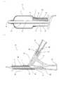
図2は、本発明の第1の実施形態であって、カテーテル本体3が同軸状に配された内外2つのシングルルーメンチューブからなり、外側チューブ22(以下、アウターシャフトという場合がある。)の内壁と内側チューブ21(以下、インナーシャフトという場合がある。)の外壁とにより形成されたルーメンを有するコアキシャル構造のカテーテル本体3を備えたバルーンカテーテル1に、バルーン膨張用液体注入用チューブ6を挿入し、固定した状態のバルーン膨張用液体注入用チューブを備えたバルーンカテーテル10を示す縦断面図である。(2) Structure of balloon catheter provided with balloon inflation liquid injection tube FIG. 2 shows a first embodiment of the present invention, from two inner and outer single lumen tubes in which the
本実施形態では、上記のとおり、カテーテル本体3は、インナーシャフト21とインナーシャフト21に同軸状に配されたアウターシャフト22とから構成されている。インナーシャフト21の外壁とアウターシャフト22の内壁とから形成されるルーメンが、バルーン膨張用液体注入用ルーメン4となり、インナーシャフト21の内壁から形成されるルーメンが、バルーンカテーテル1を誘導するガイドワイヤーが挿入されるガイドワイヤールーメン8となる。 In the present embodiment, as described above, the
バルーン膨張用液体注入用ルーメン4は、バルーン7の内部からアウターシャフト22の先端開口部(即ち、注入用ルーメン4の先端部)41、アウターシャフト22の基端開口部42を経てハブ5の注入用チューブ挿入口51(即ち、注入用ルーメンの基端開口部)と連通しており、バルーン膨張用液体注入用チューブ6は、注入用チューブ挿入口51より、その先端が注入用ルーメン4の先端部(先端開口部41)まで挿入される。この際、ハブ5の注入用チューブ挿入口51の内面の一部と注入用チューブコネクター62の外面の一部が密着し、注入用チューブ6がバルーンカテーテル1に固定されるため、注入用チューブ6の先端が軸方向に移動することが防止されることから、注入用チューブ6の先端のバルーン7内部への侵入、およびそれによるバルーンの損傷を防止できる。両者が密着して固定される部分の構造は、密着の確実性、脱着の容易性等の観点から一般的なカテーテルにおいて公知である雌および雄ルアーテーパー構造が好ましい。 The balloon inflation
また、バルーン膨張用液体注入用ルーメン4にバルーン膨張用液体注入用チューブ6が挿入され、注入用チューブコネクター62がハブ5に内嵌状態に装着、固定されることにより、注入用ルーメン4を形成するカテーテル本体3の内面(即ち、アウターシャフト22の内壁とインナーシャフト21の外壁とで構成される面)と、注入用チューブ6の外壁との間に間隙43が形成されるとともに、注入用チューブコネクター62外面とハブ5の内面(注入用チューブ挿入口51の内面)との嵌合面に間隙43に連通する通路(本実施形態では溝63)が形成される。これにより、注入用チューブコネクター62から注入されたバルーン膨張用液体が注入用チューブ本体61のルーメン66を通ってバルーン7内部に注入されるに従い、バルーン内部に予め存在した空気が間隙43を通って溝63から外部に排気され、バルーン7内部、間隙43をバルーン膨張用液体で満たすことができる。 Also, the balloon inflation
ガイドワイヤールーメン8は、インナーシャフト21の先端開口部81からその基端開口部82を経てハブ5のガイドワイヤー挿入口52と連通するように設けられ、バルーンカテーテル1を脈管内の目的の部位に誘導する際にガイドワイヤーが挿入される。また、ガイドワイヤールーン8は、薬液等を注入する際の通路(薬剤注入用ルーメン)として用いることもできる。 The
図3は、本発明の第2の実施形態であって、平行に配された2つのルーメンを有する1つのダブルルーメンチューブで構成されるバイアキシャル構造のカテーテル本体3’を有するバルーンカテーテル1’に、バルーン膨張用液体注入用チューブ6を挿入して構成した、バルーン膨張用液体注入用チューブを備えたバルーンカテーテル10’を示す縦断面図である。 FIG. 3 shows a second embodiment of the present invention, in which a balloon catheter 1 ′ having a biaxially structured
本実施形態では、注入用ルーメン4’は、バルーン7’の内部から、ダブルルーメンチューブ23の第1の先端開口部(即ち、注入用ルーメン4’の先端部)41’および第1の基端開口部42’を経て、ハブ5の注入用チューブ挿入口51と連通し、また、ガイドワイヤールーメン8’は、ダブルルーメンチューブ23の第2の先端開口部81’からその基端開口部82’を経てハブ5のガイドワイヤー挿入口52と連通するように設けられている。 In the present embodiment, the
本実施形態のカテーテル本体3’は、上記のように2つのルーメンが平行に配置されたダブルルーメンチューブ(以下、ダブルルーメンシャフトという場合がある。)23からなり、一方がバルーン膨張用液体注入用ルーメン4’、他方がガイドワイヤールーメン8’となる。
バルーン膨張用液体注入用チューブ6が注入用チューブ挿入口51より、その先端が注入用ルーメン4’の先端部(先端開口部41’)まで挿入されて、注入用チューブ6の先端が軸方向に移動することが防止される点については、上述の第1の実施形態の説明から理解できるので、その説明は省略する。The
The balloon inflating
また、本実施形態では、バルーン膨張用液体注入用ルーメン4’にバルーン膨張用液体注入用チューブ6’が挿入され、注入用チューブコネクター62がハブ5に内嵌状態に装着、固定されることにより、注入用ルーメン4’を形成するカテーテル本体3’の内面(即ち、注入用ルーメン4’を構成する内壁面)と、注入用チューブ6の外壁との間に間隙43’が形成されるとともに、注入用チューブコネクター62外面とハブ5の内面(即ち、注入用チューブ挿入口51の内面)との嵌合面に間隙43’に連通する通路(本実施形態では溝63)が形成される。これにより、バルーン7’内部、間隙43’をバルーン膨張用液体で完全に満たすことができる点は第1の実施形態と同様である。 In this embodiment, the balloon inflation
図4は、本発明の第3の実施形態であって、1つのシングルルーメンチューブから構成されたカテーテル本体3’’を有するバルーンカテーテル1’’に、バルーン膨張用液体注入用チューブ6を挿入して構成した、バルーン膨張用液体注入用チューブを備えたバルーンカテーテル10’’を示す縦断面図である。 FIG. 4 shows a third embodiment of the present invention, in which a balloon inflation
本実施形態では、前記のとおり、カテーテル本体3’’は、1つのシングルルーメンチューブ(以下、シングルルーメンシャフトという場合がある。)24、即ち、1つのルーメンのみを有する1つのシャフトから構成され、この1つのルーメンが、バルーン膨張用液体注入用ルーメン4’’となる。また注入用ルーメン4’’は、バルーン7’’の内部からシングルルーメンシャフト24の先端開口部(即ち、注入用ルーメン4’’の先端部)41’’および基端開口部42’’を経てハブ5’の注入用チューブ挿入口51’と連通している。バルーン膨張用液体注入用チューブ6は、注入用チューブ挿入口51’より、その先端が注入用ルーメン4’’の先端部41’’まで挿入される。 In the present embodiment, as described above, the catheter body 3 '' is composed of one single lumen tube (hereinafter sometimes referred to as a single lumen shaft) 24, that is, one shaft having only one lumen, This one lumen becomes the balloon inflating
本実施形態では、カテーテル本体3’’がシングルルーメンシャフト24により形成されているため、ガイドワイヤーによる誘導が必要な際は、注入用ルーメン4’’がガイドワイヤールーメンを兼ねることになる。 In this embodiment, since the
バルーン膨張用液体注入用チューブ6が、注入用ルーメン4’’に挿入され、その先端が、注入用ルーメン4’’の先端部(先端開口部41’’)まで挿入されて、注入用チューブ6の先端が軸方向に移動することが防止される点については、上述の第1の実施形態の説明から理解できるので、その説明は省略する。 The balloon inflating
図2〜4を参照しつつ、第1ないし第3の実施形態を説明したが、本発明の実施形態はこれらに限定されるものではなく、ガイドワイヤールーメンの基端開口部がカテーテル本体の基端部と先端部の間に設けられている形態や、同軸状に配された内外3つのシングルルーメンチューブから構成し、相互に近接する外側チューブの内壁と内側チューブの外壁とで形成される2つのルーメンおよび最内側チューブのルーメンから構成されている形態や、平行に配置された2つ以上のシングルルーメンチューブを束ねた形態なども可能である。 Although the first to third embodiments have been described with reference to FIGS. 2 to 4, the embodiments of the present invention are not limited thereto, and the proximal end opening of the guide wire lumen is the base of the catheter body. Formed between the end portion and the tip portion, or composed of three inner and outer single lumen tubes arranged coaxially, and formed by the inner wall of the outer tube and the outer wall of the inner tube adjacent to each other It is also possible to adopt a configuration in which two lumens and a lumen of the innermost tube are formed, or a configuration in which two or more single lumen tubes arranged in parallel are bundled.
(3)バルーンカテーテル
バルーンカテーテル1、1’および1’’のカテーテル本体3、3’および3’’の外径は特に制限はされない。いずれの部位の外径も細ければ細いほど、脈管内における屈曲部、狭窄部および末梢部位へのカテーテル挿入性は向上するが、バルーン7、7’および7’’の膨張および収縮の応答性に大きな影響を及ぼす注入用ルーメン4、4’および4’’の径方向の断面積やシャフトの耐圧強度などを考慮に入れて選択する必要がある。カテーテル本体3、3’および3’’の最大外径について一例を挙げると、PTCA用のバルーンカテーテルの場合、0.45mmから1.30mm、好ましくは0.55mmから1.15mmである。0.45mmより小さいとカテーテル挿入性は向上するものの、耐圧強度が不足する傾向にあり、1.30mmより大きいと耐圧強度は向上するものの、カテーテル挿入性が困難となる傾向にある。(3) Balloon catheter The outer diameters of the
バルーンカテーテル1、1’および1’’のカテーテル本体3、3’および3’’の材質は特に限定されることはなく、例えば、ポリプロピレン、ポリエチレン、エチレン−酢酸ビニル共重合体等のポリオレフィン、ポリアミド、ポリエチレンテレフタレート、ポリブチレンテレフタレート等のポリエステル、ポリウレタン、ポリ塩化ビニル、ポリスチレン系樹脂、エチレン−テトラフルオロエチレン共重合体等のフッ素系樹脂、ポリイミド等各種可撓性を有する樹脂や、ポリアミドエラストマー、ポリエステルエラストマー、ポリウレタンエラストマー、ポリスチレンエラストマー、フッ素系エラストマー、シリコーンゴム、ラテックスゴム等の各種エラストマー、またはこれらのうちの2以上を組み合わせたものが使用可能である。 The material of the
バルーン7、7’および7’’が拡張されたときのバルーンの寸法としては、外径が0.50mmから35.00mm、好ましくは1.00mmから30.00mmであり、バルーンの長さが2.00mmから80.00mm、好ましくは3.00mmから60.00mmである。バルーン拡張時の外径が0.50mmより小さいと・・・、35.00mmより大きいと・・・であり、その長さが2.00mmより小さいと・・・、80.00mmより大きいと・・・となる傾向にある。 The dimensions of the balloon when the
バルーン7、7’および7’’に使用される樹脂は特に限定されるものではなく、例えば、ポリオレフィン、ポリオレフィンエラストマー、ポリエステル、ポリエステルエラストマー、ポリアミド、ポリアミドエラストマー、ポリウレタン、ポリウレタンエラストマー、ポリエチレンテレフタレート、ラテックス、シリコンゴム、スチレンオレフィンゴムなどが使用可能であり、これらの樹脂の2種類以上を混合したブレンド材料や2種類以上を積層した多層構造を有する材料であっても構わない。 The resin used for the
バルーン7、7’および7’’の製造方法としてはディッピング成形、ブロー成形等があり、使用用途に応じて適切な方法を選択することができる。心臓の冠状動脈の狭窄部を拡張治療するバルーンカテーテル1の場合は、十分な耐圧強度を得るためにブロー成形が好ましい。ブロー成形によるバルーンの製造方法の一例を以下に示す。まず、押出成形等により任意寸法のチューブ状パリソンを成形する。このチューブ状パリソンをバルーン形状に一致する型を有する金型内に配置し、二軸延伸工程により軸方向と径方向に延伸することにより、前記金型と同一形状のバルーン7を成形する。尚、二軸延伸工程は加熱条件下で行われても良いし、複数回行われても良い。また、軸方向の延伸は径方向の延伸と同時に若しくはその前後に行われても良い。さらに、バルーン7の形状や寸法を安定させるために、アニーリング処理を実施しても良い。また、血流を遮断させる目的で使用するバルーンカテーテル1の場合には、ブロー成型以外にもディッピング成型や押出成型したチューブを加工することによりバルーン7を製造することが可能である。
ハブ5は、図2(b)および図3(d)に示すように、先端側開口部でカテーテル本体3、3’と接合し、その基端側には、カテーテル本体3、3’の注入用ルーメン4、4’と連通する注入用チューブ挿入口51、および、ガイドワイヤールーメン8、8’と連通するガイドワイヤー挿入口52を備える。ガイドワイヤー挿入口51、51’は、その内面にバルーン膨張用液体注入用チューブ6の注入用チューブコネクター62と嵌合できる構造を有するとともに、シリンジ、三方活栓、Yコネクター等を接続できるように雌ルアーテーパー構造を有することが好ましい。更に、ガイドワイヤー挿入口51、51’の外面には、ロック機構付きのシリンジ、三方活栓、Yコネクター等が接続できるように、その端部外側にフランジ(突起部)や二条ネジ等を有することがより好ましい。 As shown in FIGS. 2B and 3D, the
またハブ5および5’を構成する材質としては、ポリカーボネート、ポリアミド、ポリウレタン、ポリサルホン、ポリアリレート、スチレン−ブタジエンコポリマー、ポリオレフィン等の各種樹脂が好適に使用できる。 As the material constituting the
バルーンカテーテル1、1’および1’’の各チューブ、バルーン、ハブなどの各部材の接合方法としては、接着剤による接着、融着可能な材質の組み合わせである場合は融着等の方法が使用可能である。接着剤を使用する場合、接着剤の組成及び化学構造、硬化形式は限定されない。つまり、組成及び化学構造の点からは、ウレタン型、シリコン型、エポキシ型、シアノアクリレート型等の接着剤が好適に使用され、硬化形式の点からは、2液混合型、UV硬化型、吸水硬化型、加熱硬化型等の接着剤が好適に使用される。 As a method for joining each member such as each tube, balloon, and hub of the balloon catheter 1, 1 ′ and 1 ″, a method such as fusion is used in the case of a combination of materials that can be bonded and fused with an adhesive. Is possible. When an adhesive is used, the composition and chemical structure of the adhesive and the type of curing are not limited. That is, from the viewpoint of composition and chemical structure, adhesives such as urethane type, silicon type, epoxy type and cyanoacrylate type are preferably used, and from the viewpoint of curing type, two-component mixed type, UV curing type, water absorption Adhesives such as a curable type and a heat curable type are preferably used.
接着剤を使用する場合、接続部位の剛性が、該接続部位の前後で不連続に変化しない程度の硬化後の硬度を有する接着剤を使用することが好ましく、接続部位の材質、寸法、剛性等を考慮して接着剤を選択することが可能である。また、接続部位の細径化を実現するために接続部を加熱処理しても良く、ポリオレフィン等の難接着性の材質の場合は、接続部位を酸素ガス等でプラズマ処理し接着性を向上させた上で接着しても良い。 When using an adhesive, it is preferable to use an adhesive having a hardness after curing such that the rigidity of the connection site does not change discontinuously before and after the connection site, such as the material, dimensions, rigidity, etc. of the connection site It is possible to select an adhesive in consideration of the above. In order to reduce the diameter of the connection part, the connection part may be heat-treated. In the case of a difficult-to-adhere material such as polyolefin, the connection part is plasma treated with oxygen gas or the like to improve the adhesion. Adhesion may also be made.
融着により接続する場合には、必要なルーメンを確保するために、任意寸法・形状の芯材を挿入しても良い。この場合、加工終了後に芯材を除去することを考慮すると芯材の外表面にはポリテトラフルオロエチレン等のフッ素系樹脂やポリパラキシリレン、ポリモノクロロパラキシリレン等をコーティングしておき、芯材を除去しやすくしておくことが好ましい。使用する前記芯材の寸法や断面形状等は本発明の効果を何ら制限するものではなく、加工時の作業性や必要とされるルーメンの断面積等を考慮して決定され得る。 When connecting by fusion, a core material having an arbitrary size and shape may be inserted in order to secure a required lumen. In this case, considering the removal of the core material after finishing the processing, the outer surface of the core material is coated with a fluorine-based resin such as polytetrafluoroethylene, polyparaxylylene, polymonochloroparaxylylene, etc. It is preferable to make the material easy to remove. The dimensions, cross-sectional shape, and the like of the core material to be used do not limit the effects of the present invention, and can be determined in consideration of workability during processing, a required cross-sectional area of the lumen, and the like.
図2ないし図4には図示されていないが、本発明のバルーンカテーテル1、1’および1’’には、コアワイヤー、X線不透過マーカー、および先端チップが設けられていても良い。コアワイヤーの役割は、ガイドワイヤーに沿って体外からバルーンカテーテル1を押し進めていく際の操作性を向上させ、バルーンカテーテル1のキンク(折れ)を防止することであり、使用される材料種については特に制限を受けない。コアワイヤーの寸法や取付け位置についても、カテーテル本体3の寸法や材質、使用目的等を考慮して決定することができる。 Although not shown in FIGS. 2 to 4, the balloon catheters 1, 1 ′ and 1 ″ of the present invention may be provided with a core wire, a radiopaque marker, and a tip. The role of the core wire is to improve operability when the balloon catheter 1 is pushed forward from the outside of the body along the guide wire, and to prevent the balloon catheter 1 from being kinked. There are no particular restrictions. The dimensions and attachment position of the core wire can also be determined in consideration of the dimensions and material of the
X線不透過マーカーに関しては、本発明のバルーンカテーテル1、1’および1’’を用いた治療中にバルーンカテーテル1、1’および1’’の特定部位の視認性を向上させ、バルーンカテーテル1の位置決めを容易に行うことを目的として設けてもよい。X線不透過マーカーはX線不透過性を有する材料であれば良く、金属や樹脂等の材料の種類は問われない。また、設ける位置、個数等も問われず、バルーンカテーテル1、1’および1’’の使用目的に応じて設定することが可能である。 Regarding the radiopaque marker, the visibility of specific parts of the balloon catheter 1, 1 ′ and 1 ″ is improved during the treatment using the balloon catheter 1, 1 ′ and 1 ″ of the present invention. May be provided for the purpose of facilitating positioning. The radiopaque marker may be any material that has radiopacity, and any type of material such as metal or resin may be used. Further, the position, the number, and the like of the balloon catheters 1, 1 ′, and 1 ″ can be set according to the purpose of use regardless of the position and number of the balloon catheters.
先端チップは、バルーンカテーテル1、1’の最先端部に取り付けることができる。前記第1および第2の実施形態では、ガイドワイヤールーメン8、8’を形成するシャフトの材質より柔軟な材質により成形した先端チップを、ガイドワイヤールーメン8を構成するシャフトの最先端部(第1の実施形態では、インナーシャフト21の最先端部である先端開口部81。第2の実施形態では、ダブルルーメンシャフト23の第2の先端開口部81’。)に取付けてもよい。これによりガイドワイヤーに沿って体外からバルーンカテーテル1、1’を押し進めていく際の挿入部位の選択の幅を広げることや操作性を向上させることが可能になる。なお、血管損傷の可能性を低減することを目的に、先端チップはその最先端が丸め加工もしくはテーパー加工されていることがより好ましい。 The tip can be attached to the tip of the balloon catheter 1, 1 '. In the first and second embodiments, the tip of the tip of the shaft constituting the guide wire lumen 8 (the first tip) formed from a material that is more flexible than the material of the shaft that forms the
バルーンカテーテル1、1’、1’’の外面には、血管内或いはガイドカテーテル内への挿入を容易にする為に親水性のコーティング(図示せず)を施すことができる。すなわち、カテーテル本体3、3’、3’’の外面およびバルーン7、7’、7’’の外面等の血液と接触する部位の少なくとも一部に血液と接触した際に潤滑性を呈する親水性のコーティングを施すことが可能である。但し、親水性のコーティングを施す部位、施す長さについてはバルーンカテーテル1、1’、1’’の使用目的に応じて決定できる。親水性のコーティングの種類は本発明の効果を制限するものではなく、ポリ(2−ヒドロキシエチルメタアクリレート)、ポリアクリルアミド、ポリビニルピロリドン等の親水性ポリマーが好適に使用でき、コーティング方法も限定されない。 A hydrophilic coating (not shown) can be applied to the outer surface of the balloon catheter 1, 1 ′, 1 ″ to facilitate insertion into a blood vessel or guide catheter. That is, the hydrophilicity which exhibits lubricity when contacting at least a part of the blood-contacting portions such as the outer surfaces of the
バルーンカテーテル1、1’、1’’の使用目的によっては、バルーン7、7’、7’’の拡張時にスリッピングを生じないように、バルーン7、7’、7’’の外面に疎水性のコーティング(図示せず)を施すことができる。疎水性のコーティングの種類は特に限定されず、シリコン等の疎水性ポリマーが好適に使用できる。 Depending on the intended use of the balloon catheter 1, 1 ′, 1 ″, the outer surface of the
(4)バルーン膨張用液体注入用チューブ
バルーン膨張用液体注入用チューブ6は、図2〜4に示すように、注入用チューブ挿入口51、51’より、その先端が注入用ルーメン4、4’、4’’内の先端まで挿入される注入用チューブ本体61と、注入用チューブ本体61の基端部に接着、融着、一体成形等の公知の方法で取り付けられた注入用チューブコネクター62とから構成される。注入用チューブ本体61は、その先端部で開口し、その基端部で注入用チューブコネクター62の基端開口部と連通したルーメン66を有する。なお、注入用チューブコネクター62の基端開口部65は、その内面が、ハブ5、5’のバルーン膨張用液体注入用チューブ挿入口52、52’の内面と同様にシリンジ、三方活栓、Yコネクター等を接続できるように雌ルアーテーパー構造であることが好ましく、また、その端部外側に、ロック機構付きのシリンジ、三方活栓、Yコネクター等が接続できるようフランジ(突起部)や二条ネジ等を有することがより好ましい。(4) Balloon Inflating Liquid Injection Tube As shown in FIGS. 2 to 4, the balloon inflating
注入用チューブコネクター62は、図2ないし図4に示すように、ハブ5、5’に内嵌状態に装着して固定される。即ち、コネクター62はその外面がハブ5、5’のバルーン膨張用液体注入用チューブ挿入口51、52’の内面に密着し固定される構造を有する。上述の通り、両者が密着する部分の構造は、一般的なカテーテルにおいて公知である雌および雄ルアーテーパー構造が好ましい。バルーン膨張用液体注入用チューブ挿入口51、51’に確実に密着するために、注入用チューブコネクター62にロック機構(図示せず)を設けても良い。 As shown in FIGS. 2 to 4, the
また、図5に示す通り、バルーン膨張用液体注入用チューブ挿入口51、51’の内周面に密着する注入用コネクター62の外周面に、少なくとも1つの溝63を、注入用チューブ本体61の軸方向に沿って設けても良い。これにより、図2〜4に示すように、後述する使用方法に基づき、注入用コネクター62の基端開口部65からバルーン膨張用液体を注入する際に、注入用ルーメン4、4’、4’’を形成するカテーテル本体3、3’、3’’の内面と、注入用チューブ6の外壁との間に間隙43、43’、43’’が形成されるとともに、注入用チューブコネクター62外面とハブ5、5’の内面(注入用チューブ挿入口51、51’の内面)との嵌合面に間隙43、43’、43’’に連通する通路が形成され、注入用コネクター62の溝63により形成される通路から、より効果的にバルーン7、7’、7’’および注入用ルーメン4、4’、4’’内の気体を外部に排出することができる。 Further, as shown in FIG. 5, at least one
注入用チューブコネクター62を構成する材質としては、ハブ5、5’と同様に、ポリカーボネート、ポリアミド、ポリウレタン、ポリサルホン、ポリアリレート、スチレン−ブタジエンコポリマー、ポリオレフィン等の各種樹脂が好適に使用できる。 As the material constituting the
注入用チューブ本体61は、その先端開口部から基端開口部に亘りバルーン膨張用液体を注入するためのルーメン66を有する筒状体であり、その先端部の形状および先端部近傍の構造は特に制限されない。先端開口部の形状としては、例えば、筒状体を軸方向に対して垂直に切断した断端面の形状、あるいは軸方向に対して斜めに切断した断端面の形状などが例示できる。より具体的には、図6に示すように、先端開口部64を、円筒を軸方向に対して斜めに切断した断端面の形状として楕円状とすることができ、また、図7に示すように、先端開口部64’を、円筒を軸方向に対して垂直に切断した断端面の形状として円状とすることができる。先端開口部の形状が、筒状体を軸方向に対して斜めに切断した断端面の形状である場合は、垂直の場合より開口部が広くなるため、バルーン膨張用液体の注入抵抗を低減できる。 The injection tube
また、先端部近傍の構造としては、図6に示すように、先端開口部64のみを有するものや、図7に示すように、先端部近傍周面に少なくとも1つのルーメン66’に連通する開口部(側孔)67が設けられているものが例示できる。これにより、バルーン7および注入用ルーメン4内に、注入用コネクター62の基端開口部からバルーン膨張用液体を注入する際の注入抵抗をより低減することができる。側孔の数、その大きさは特に制限はなく、注入抵抗を改善できるように適宜決定することができる。尚、図7では、合計6か所に側孔を設けてある。 Further, as the structure near the tip, as shown in FIG. 6, the structure having only the tip opening 64 or the opening communicating with at least one
注入用チューブ本体61、61’を構成する材質としては、細径のチューブを形成できるものであればいかなるものでもよく、例えば、ステンレス鋼、Ni−Ti合金、Ni−Ti−Co合金、Ni−Al合金、Cu−Zn合金、Cu−Zn−X合金(例えば、X=Be、Si、Sn、Al、Ga)のような超弾性合金、アモルファス合金等の各種金属材料や、例えば、ポリプロピレン、ポリエチレン、エチレン−酢酸ビニル共重合体等のポリオレフィン、ポリアミド、ポリエチレンテレフタレート、ポリブチレンテレフタレート等のポリエステル、ポリウレタン、ポリ塩化ビニル、ポリスチレン系樹脂、エチレン−テトラフルオロエチレン共重合体等のフッ素系樹脂、ポリイミド等各種可撓性を有する樹脂や、ポリアミドエラストマー、ポリエステルエラストマー、ポリウレタンエラストマー、ポリスチレンエラストマー、フッ素系エラストマー、シリコーンゴム、ラテックスゴム等の各種エラストマー、またはこれらのうちの2以上を組み合わせたものが使用可能である。 The material constituting the injection tube
注入用チューブ本体61、61’の内径および外径は特に制限はされないが、注入用ルーメン4、4’、4’’の寸法などを考慮に入れて選択する必要がある。外径について一例を挙げると、PTCA用のバルーンカテーテルの場合、外径は0.20mmから1.00mm、好ましくは0.30mmから0.80mmである。 The inner and outer diameters of the
(5)使用方法
次に、第1の実施形態をもとに、本発明のバルーン膨張用液体注入用チューブを備えたバルーンカテーテル10の使用方法を説明する。本発明のバルーンカテーテル1は、バルーン膨張用液体注入用チューブ挿入口51より、バルーン膨張用液体注入用チューブ6が注入用ルーメン4内に挿入され、注入用チューブ挿入口51の内面の一部と、注入用チューブコネクター62の外面の一部が密着し、注入用チューブ6の先端が、注入用ルーメン4内の先端まで挿入された状態で提供される。(5) Usage method Next, based on 1st Embodiment, the usage method of the
シリンジ(図示せず)に、血管造影剤と生理食塩液の混合液等のバルーン膨張用液体を満たし、注入用チューブコネクター62の基端開口部65に嵌める。注入用チューブ本体61を通じて、注入用チューブ6の先端からバルーン7にバルーン膨張用液体を注入すると、同時にバルーン7および注入用ルーメン4内の気体は外部に排出されようとする。 A syringe (not shown) is filled with a balloon inflation liquid such as a mixture of an angiographic contrast medium and physiological saline, and is fitted into the proximal end opening 65 of the
この際、仮に注入用チューブ挿入口51の内面と、注入用チューブコネクター62の外面が完全に密着した状態では、気体は外部に排出されない。したがって、バルーン7の内部がバルーン膨張用液体で満たされたことを目視で確認した後、注入用チューブコネクター62を注入用チューブ挿入口51から外し、バルーン膨張用液体を注入し続けながら注入用チューブ6を徐々に抜去しなければならない。 At this time, if the inner surface of the injection
これに対して、本発明のバルーンカテーテルでは、図5に示す通り、バルーン膨張用液体注入用チューブ挿入口51の内側に密着する注入用コネクター62の外周面に、少なくとも1つの溝63が、注入用チューブ本体61の軸方向に沿って設けられているため、バルーン7および間隙43内の気体は、注入用ルーメン4を通じて、溝63により形成される通路から外部に排出される。したがって、バルーン7の内部がバルーン膨張用液体で満たされたことを目視で確認する必要はなく、溝63により形成される隙間からバルーン膨張用液体が外部に流出したことを確認した後、注入用チューブコネクター62を注入用チューブ挿入口51から外し、バルーン膨張用液体を注入し続けながら注入用チューブ6を徐々に抜去する。これにより、注入用チューブ6を抜去することにより生じる注入用ルーメン4の空間に気体が流入、残存しないようにすることを容易に行うことができる。 On the other hand, in the balloon catheter of the present invention, as shown in FIG. 5, at least one
本発明のバルーンカテーテル1では、注入用チューブ6がハブ5と密着し、固定されているため、上述の操作を行なう際の操作性が良く、注入用チューブ6の先端でバルーンを破損する恐れもない。また、バルーン7および注入用ルーメン4内の気体を完全に排出すべく、バルーン膨張用液体を注入用ルーメン4内に注入してからシリンジと三方活栓を用いて繰返し吸引する等の煩雑な操作も不要である。 In the balloon catheter 1 of the present invention, since the
上述の操作により、バルーン7および注入用ルーメン4内の気体を外部に排出した後、血管造影剤と生理食塩液の混合液等のバルーン膨張用液体を満たしたシリンジを、バルーン7および注入用ルーメン4に連通する注入用チューブ挿入口51に嵌め、バルーン7の膨張および収縮を確認する。上述の操作は、いずれも患者の脈管内に挿入する前に、体外で行なわれ、バルーン7の膨張および収縮を確認した後、脈管内に挿入される。 After the gas in the
以上、本発明のバルーンカテーテルの形状、構造および使用方法等を図示の実施形態と併せて説明したが、本発明はこれらに限定されるものではなく、本発明におけるバルーンカテーテルの用途も特に限定されるものではないが、本発明のバルーンカテーテルは、バルーンおよび注入用ルーメン内の気体を煩雑な操作を伴わず容易に外部に排出することを可能とする効果を発揮し、バルーンが膨張された形状通りにX線造影されることから、とりわけ、脳動脈瘤に塞栓コイルを挿入する際、動脈瘤根元付近でバルーンを拡張させることによってコイルの脱落を防止するバルーンカテーテルに好適に用いることができる。 As described above, the shape, structure, usage method and the like of the balloon catheter of the present invention have been described together with the illustrated embodiments. However, the present invention is not limited to these, and the use of the balloon catheter in the present invention is also particularly limited. Although not intended, the balloon catheter of the present invention exhibits an effect that allows the gas in the balloon and the lumen for injection to be easily discharged outside without complicated operation, and the balloon is inflated. In particular, since the X-ray imaging is performed, when the embolic coil is inserted into the cerebral aneurysm, it can be suitably used for a balloon catheter that prevents the coil from falling off by expanding the balloon in the vicinity of the root of the aneurysm.
次に本発明の実施例について説明する。以下の実施例に含まれる各要素は、便宜上、上述の各実施形態で説明した各要素の符号に対応づけて説明する。
(実施例1)
まず、ポリアミドエラストマー(PEBAX7033SA01:アルケマ社製)を用いて押出成形によりチューブ状パリソン(内径0.40mm、外径0.84mm)を作製し、次いでこのパリソンを用いて二軸延伸ブロー成形を行い、直管部の外径が3.0mm、直管部の長さが15mmのバルーン7を成形した。Next, examples of the present invention will be described. For convenience, each element included in the following examples will be described in association with the reference numerals of the elements described in the above embodiments.
Example 1
First, a tubular parison (inner diameter 0.40 mm, outer diameter 0.84 mm) is produced by extrusion molding using a polyamide elastomer (PEBAX7033SA01: manufactured by Arkema Inc.), and then biaxial stretch blow molding is performed using this parison. A
インナーシャフト21(内径0.30mm、外径0.40mm)は、高密度ポリエチレン(HB530:日本ポリケム株式会社 内層)、低分子量ポリエチレン(プレクサー3080:エキスタ社製 中間層)、ポリアミドエラストマー(PEBAX7233SA01:アルケマ社製 外層)を用いて押出成形により形成し、アウターシャフト22(内径0.84mm、外径0.90mm)は、ポリアミドエラストマー(PEBAX7233SA01:アルケマ社製)を用いて押出成形により形成した。 Inner shaft 21 (inner diameter 0.30 mm, outer diameter 0.40 mm) is made of high-density polyethylene (HB530: Nippon Polychem Co., Ltd. inner layer), low molecular weight polyethylene (Plexer 3080: intermediate layer manufactured by Exta), polyamide elastomer (PEBAX7233SA01: Arkema). The outer shaft 22 (inner diameter 0.84 mm, outer diameter 0.90 mm) was formed by extrusion molding using a polyamide elastomer (PEBAX7233SA01: manufactured by Arkema).
次に、1280mmに切断したアウターシャフト22の先端とバルーン7の後端とを熱溶着により接合した後、バルーン7を熱溶着したアウターシャフト22と1350mmに切断したインナーシャフト21とを、同軸二重管状に配置し、バルーン7の先端とインナーシャフト21の先端を熱溶着により接合した。 Next, the front end of the
別途、ポリカーボネート(Makloron2658:Bayer社製)を用いて、バルーン膨張用液体注入用チューブ挿入口51とガイドワイヤー挿入口52とを有するハブ5を射出成形にて成形した。また、バルーン膨張用液体注入用チューブ挿入口51およびガイドワイヤー挿入口52の基端開口部は、それぞれ外側に二条ネジを有する雌ルアーテーパー構造とした。 Separately, using a polycarbonate (Makloron 2658, manufactured by Bayer), the
この後、インナーシャフト21の基端開口部82がバルーン膨張用液体注入用チューブ挿入口51と、アウターシャフト22の基端開口部42がガイドワイヤー挿入口52と、それぞれ連通するよう、2液混合型ウレタン系接着剤(UR0531:H.B.Fuller社製)と用いてハブ5を接着してバルーンカテーテルを作製した。 Thereafter, the two-component mixing is performed so that the proximal end opening 82 of the
一方、円筒のステンレス管を軸方向に対し斜めに切断して先端開口部を楕円状に加工し、面取り処理を施した後、ポリテトラフルオロエチレンコーティングを施したSUS304ステンレス管からなる注入用チューブ本体61(内径0.23mm、外径0.31mm、長さ1325mm)と、ポリカーボネート(Makloron2658:Bayer社製)を用いて射出成形にて成形した、先端部が雄ルアーテーパー構造であり先端部外周面に溝63を有する注入用チューブコネクター62とをそれぞれ作製しておき、2液混合型ウレタン系接着剤(UR0531:H.B.Fuller社製)を用いて注入用チューブ本体61基端部に、注入用チューブコネクター62を接着してバルーン膨張用液体注入用チューブ6を作製した。 On the other hand, a cylindrical stainless steel tube is cut obliquely with respect to the axial direction, the tip opening is processed into an oval shape, chamfered, and then a polytetrafluoroethylene-coated SUS304 stainless steel tube body. 61 (inner diameter: 0.23 mm, outer diameter: 0.31 mm, length: 1325 mm) and polycarbonate (Makloron 2658: manufactured by Bayer) were molded by injection molding. The tip has a male luer taper structure and the outer periphery of the tip An
上述の通りに作製したバルーンカテーテルのバルーン膨張用液体注入用チューブ挿入口51から、上述の通りに作製したバルーン膨張用液体注入用チューブ6を挿入し、バルーン膨張用液体注入用チューブ挿入口51に注入用チューブコネクター62を密着させて、本発明のバルーンカテーテル1を得た。 The balloon inflation
(実施例2)
注入用チューブ本体61’の先端開口部を楕円状に加工せず、注入用チューブ本体61’の先端から2.5、5.0、7.5mmの位置に直径0.05mmの側孔を設けたことを除き、上記実施例1のバルーンカテーテルと同様に作製した。(Example 2)
The end opening of the injection tube
(比較例1)
先端部に雄ルアーテーパー構造を有する注入用チューブコネクターの先端部外周面に溝を設けないことを除き、上記実施例1のバルーンカテーテルと同様に作製した。(Comparative Example 1)
It was produced in the same manner as the balloon catheter of Example 1 except that no groove was provided on the outer peripheral surface of the distal end portion of the tube connector for injection having a male luer taper structure at the distal end portion.
(比較例2)
注入用チューブ本体の先端開口部の形状が円形であること、すなわち注入用チューブ本体の先端部を加工しないことを除き、上記比較例1のバルーンカテーテルと同様に作製した。(Comparative Example 2)
The injection tube body was prepared in the same manner as the balloon catheter of Comparative Example 1 except that the shape of the distal end opening of the injection tube body was circular, that is, the distal end portion of the injection tube body was not processed.
(比較例3)
注入用チューブ本体の長さが1350mmであることおよび注入用チューブコネクターの先端部がルアーテーパー構造でないことを除き、上記比較例1のバルーンカテーテルと同様に作製した。
なお、比較例3では、注入用チューブ本体の基端部がバルーン膨張用液体注入用チューブ挿入口から外部に出ており、バルーン膨張用液体注入用チューブ挿入口と注入用チューブコネクターとが密着していなかった。(Comparative Example 3)
It was produced in the same manner as the balloon catheter of Comparative Example 1 except that the length of the infusion tube main body was 1350 mm and the tip of the infusion tube connector was not a luer taper structure.
In Comparative Example 3, the proximal end portion of the injection tube main body protrudes from the balloon expansion liquid injection tube insertion port, and the balloon expansion liquid injection tube insertion port and the injection tube connector are in close contact with each other. It wasn't.
(比較例4)
注入用チューブ本体の長さが1350mmであることおよび注入用チューブコネクターの先端部がルアーテーパー構造でないことを除き、上記比較例2のバルーンカテーテルと同様に作製した。
なお、比較例4では、注入用チューブ本体の基端部がバルーン膨張用液体注入用チューブ挿入口から外部に出ており、バルーン膨張用液体注入用チューブ挿入口と注入用チューブコネクターとが密着していなかった。(Comparative Example 4)
It was produced in the same manner as the balloon catheter of Comparative Example 2 except that the length of the injection tube main body was 1350 mm and the tip of the injection tube connector was not a Luer taper structure.
In Comparative Example 4, the proximal end portion of the injection tube main body protrudes outside from the balloon inflation liquid injection tube insertion port, and the balloon inflation liquid injection tube insertion port and the injection tube connector are in close contact with each other. It wasn't.
(評価1)気体の排出のしやすさ
上記各実施例および各比較例において作製したバルーン膨張用液体注入用チューブを備えたバルーンカテーテルの、バルーンおよび注入用ルーメン内の気体の排出しやすさを確認するために、造影剤(イオパミロン350:日本シェーリング社製)50%生理食塩水が10ml入ったシリンジを注入用チューブコネクターの基端開口部に嵌め、上述の使用方法に従って、バルーンおよび注入用ルーメン内の気体を外部に排出した時の気体の排出のしやすさを評価した。(Evaluation 1) Ease of gas discharge Ease of gas discharge in the balloon and the injection lumen of the balloon catheter provided with the balloon inflation liquid injection tube prepared in each of the above examples and comparative examples. To confirm, a syringe containing 10 ml of contrast medium (Iopamylon 350: manufactured by Nippon Schering Co., Ltd.) 50% physiological saline is fitted into the proximal end opening of the tube connector for injection, and the balloon and lumen for injection are used according to the above-mentioned method of use. The ease of gas discharge when the gas inside was discharged to the outside was evaluated.
評価項目は、排出度合い、バルーン膨張用液体注入用チューブの動き、注入抵抗の3項目とした。また、本願発明の評価として重要度の高い項目ほど評価結果に重み付けを行うこととした。即ち、本願発明に係るバルーンカテーテルは第1にバルーン内に残存する気体により術中の手技に支障を来たすことを回避するために注入用チューブを備えたものであることから、「排出度合」を最も重要度の高い項目と位置づけた。また本願発明に係るバルーンカテーテルは第2に術中でのバルーン損傷の可能性を低減するためにその原因の一つであるバルーン膨張用液体注入用チューブの先端部によるバルーン損傷の可能性を低減するものであることから、「バルーン膨張用液体注入用チューブの動き」の重要度を「排出度合」よりは低くした。さらに本願発明に係るバルーンカテーテルは第3により容易にバルーン内の気体を排出させる、即ち注入操作をより容易にすることを可能にするものであることから、「注入抵抗」の重要度を「バルーン膨張用液体注入用チューブの動き」より低くした。従って、評価項目「排出度合」について、バルーンおよび注入用ルーメン内の気体を完全に排出できた場合を「○」、加点「3」、完全に排出できなかった場合を「×」、加点「0(ゼロ)」とし、評価項目「バルーン膨張用液体注入用チューブの動き」については、動きがなかった場合を「○」、加点「2」、動きがあった場合を「×」、加点「0(ゼロ)」、評価項目「注入抵抗」について、抵抗がなかった場合を「○」、加点「1」、抵抗があった場合を「×」、加点「0(ゼロ)」とした。尚、表1の各評価項目括弧内の数値は加点を示したものである。 The evaluation items were three items: the degree of discharge, the movement of the balloon inflating liquid injection tube, and the injection resistance. In addition, as the evaluation of the present invention, the evaluation result is weighted with respect to items having higher importance. That is, since the balloon catheter according to the present invention is provided with an infusion tube in order to avoid the trouble in the procedure during the operation due to the gas remaining in the balloon, the “exhaust degree” is the highest. It was positioned as a highly important item. The balloon catheter according to the present invention secondly reduces the possibility of balloon damage due to the distal end portion of the balloon inflating liquid injection tube, which is one of the causes in order to reduce the possibility of balloon damage during the operation. Therefore, the importance of the “movement of the balloon inflation liquid injection tube” was made lower than the “exhaust degree”. Furthermore, since the balloon catheter according to the present invention makes it possible to discharge the gas in the balloon more easily, that is, to facilitate the injection operation, the importance of “injection resistance” is set to “balloon”. Lower than "movement of expansion liquid injection tube". Therefore, regarding the evaluation item “exhaust degree”, “○” indicates that the gas in the balloon and the lumen for injection was completely discharged, “3” is added, “×” indicates that the gas was not completely discharged, and “0” is added. For the evaluation item “movement of the balloon inflation liquid injection tube”, “○” indicates that there is no movement, “2” is added, “×” indicates that there is movement, and “0” is added. Regarding (zero) ”and the evaluation item“ injection resistance ”, the case where there was no resistance was“ ◯ ”, the added point“ 1 ”, the case where there was a resistance was“ × ”, and the added point“ 0 (zero) ”. In addition, the numerical value in each evaluation item parenthesis of Table 1 shows the added point.
また、総合評価の基準としては、各項目の加点の合計を基準として、合計点が6または5の場合を「○」、即ち実際の使用において問題がないと、合計点が4の場合を「△」、即ち実際の使用において支障を来たす可能性が高いと、合計点が3以下の場合を「×」、即ち実際の使用において問題があるとした。評価は、各実施例および各比較例の構造を有するサンプルを各5つ用意し(n=5)、実施した。その結果を表1に示す。尚、表1の総合評価中、括弧内の数値は合計点を示したものである。 In addition, as a standard for the comprehensive evaluation, the sum of the added points of each item is used as a reference, and the case where the total score is 6 or 5 is “◯”, that is, the case where the total score is 4 when there is no problem in actual use. “△”, that is, when there is a high possibility of causing trouble in actual use, a case where the total score is 3 or less is regarded as “x”, ie, there is a problem in actual use. The evaluation was performed by preparing five samples each having the structure of each example and each comparative example (n = 5). The results are shown in Table 1. In addition, during the comprehensive evaluation in Table 1, the numerical values in parentheses indicate total points.
なお、比較例3および4では、注入用チューブ本体の基端部がバルーン膨張用液体注入用チューブ挿入口から外部に出ており、バルーン膨張用液体注入用チューブ挿入口と注入用チューブコネクターとが密着していないため、バルーン膨張用液体注入用チューブ挿入口からバルーン膨張用液体が流出したこと確認した後、注入用チューブを抜去した。 In Comparative Examples 3 and 4, the base end portion of the injection tube main body protrudes outside from the balloon expansion liquid injection tube insertion port, and the balloon expansion liquid injection tube insertion port and the injection tube connector are connected to each other. Since it was not in close contact, it was confirmed that the balloon inflation liquid had flowed out of the balloon inflation liquid injection tube insertion port, and then the injection tube was removed.

実施例1および2については、注入用コネクター62からバルーン膨張用液体が流出したことを確認できた時点で、5本全てで注入用チューブ6の動きはなく、バルーン7および注入用ルーメン4内の気体を外部に完全に排出することが出来た。また、注入用チューブ6を挿入された状態で、バルーン膨張用液体注入用チューブ挿入口51に注入用チューブコネクター62を密着し、かつ注入用チューブコネクター62先端部外周面に溝63を有しているため、注入用チューブ6が注入用ルーメン4内で動くことがなく、安全かつ確実にバルーン7および注入用ルーメン4内の気体を外部に排出することが出来た。 In Examples 1 and 2, when it was confirmed that the balloon inflation liquid had flowed out of the
比較例1については、5本全てで注入用チューブの動きはなかったが、バルーンおよび注入用ルーメン内の気体を外部に排出することができなかった。また、注入用チューブ先端部の開口形状が、加工を行って楕円形状としたもので、未加工の円形状のもの(比較例2)より断面積が大きいため、注入抵抗は小さかったが、バルーン膨張用液体注入用チューブ挿入口に注入用チューブコネクターを密着し、かつ注入用チューブコネクター先端部外周面に溝を有していないため、バルーンおよび注入用ルーメン内がバルーン膨張用液体で満たされた後、さらに注入を続けようとすると抵抗が大きくなった。 In Comparative Example 1, all of the five tubes did not move the injection tube, but the gas in the balloon and the injection lumen could not be discharged to the outside. In addition, the opening shape of the distal end portion of the injection tube was processed into an elliptical shape, and the injection resistance was small because the cross-sectional area was larger than that of the unprocessed circular shape (Comparative Example 2). Since the injection tube connector is closely attached to the expansion liquid injection tube insertion port, and the groove is not provided on the outer peripheral surface of the injection tube connector tip, the balloon and the injection lumen are filled with the balloon expansion liquid. Later, when the injection was continued, the resistance increased.
比較例2については、5本全てで注入用チューブの動きはなかったが、バルーンおよび注入用ルーメン内の気体を外部に排出することができなかった。また、注入用チューブ先端部の開口形状が、加工を行わない円形状であり、加工を行って楕円形状にしたもの(比較例1)より断面積が小さいため注入抵抗は大きく、また、バルーン膨張用液体注入用チューブ挿入口に注入用チューブコネクターを密着し、かつ注入用チューブコネクター先端部外周面に溝を有していないため、バルーンおよび注入用ルーメン内がバルーン膨張用液体で満たされた後、さらに注入を続けようとすると抵抗が大きくなった。 In Comparative Example 2, all of the five tubes did not move the injection tube, but the gas in the balloon and the injection lumen could not be discharged to the outside. In addition, the opening shape of the tip of the injection tube is a circular shape that is not processed, and the injection resistance is large because the cross-sectional area is smaller than that of the processed elliptical shape (Comparative Example 1). Since the injection tube connector is in close contact with the liquid injection tube insertion port and there is no groove on the outer peripheral surface of the injection tube connector, the balloon and the injection lumen are filled with the balloon inflation liquid. When I tried to continue the injection, the resistance increased.
比較例3については、注入用チューブ本体の基端部がバルーン膨張用液体注入用チューブ挿入口から外部に出ており、バルーン膨張用液体注入用チューブ挿入口と注入用チューブコネクターとが密着していないため、注入用チューブコネクターに設けた溝の有無に関係なく、注入用チューブコネクターからバルーン膨張用液体が流出したことを確認できた時点で、5本全てでバルーンおよび注入用ルーメン内の気体を外部に完全に排出することが出来たが、注入時に注入用チューブが注入用ルーメン内で動いた。なお、比較例1の場合と同様に、注入用チューブ先端部の開口形状が楕円であり断面積が大きいため注入抵抗は小さかった。 In Comparative Example 3, the base end of the injection tube main body protrudes from the balloon expansion liquid injection tube insertion port, and the balloon expansion liquid injection tube insertion port and the injection tube connector are in close contact with each other. Therefore, regardless of the presence or absence of the groove provided in the tube connector for injection, when it is confirmed that the liquid for inflating the balloon has flowed out of the tube connector for injection, the gas in the balloon and the lumen for injection is discharged with all five tubes. Although it could be completely discharged to the outside, the injection tube moved within the injection lumen during injection. As in the case of Comparative Example 1, since the opening shape of the tip of the injection tube was an ellipse and the cross-sectional area was large, the injection resistance was small.
比較例4については、比較例3と同様に、注入用コネクターからバルーン膨張用液体が流出したことを確認できた時点で、5本全てでバルーンおよび注入用ルーメン内の気体を外部に完全に排出することが出来たが、注入時に注入用チューブが注入用ルーメン内で動いた。なお、比較例2の場合と同様に、注入用チューブ先端部の開口形状が円形状であり断面積が小さいため注入抵抗は大きかった。 For Comparative Example 4, as in Comparative Example 3, when it was confirmed that the balloon inflation liquid had flowed out of the injection connector, the gas in the balloon and the injection lumen was completely discharged to the outside with all five. The injection tube moved within the injection lumen during the injection. As in the case of Comparative Example 2, since the opening shape of the distal end portion of the injection tube was circular and the cross-sectional area was small, the injection resistance was large.
上記のとおり、比較例3および4については、注入用チューブを挿入された状態で、バルーン膨張用液体注入用チューブ挿入口に注入用チューブコネクターが密着しておらず、そのため注入用チューブが注入用ルーメン内で動くため、注入用チューブを手で固定しながら操作しなければならなかった。また、比較例3および4の構造では、注入用チューブが注入用ルーメン内で動くため、注入用チューブの先端でバルーンを破損する恐れがあったことから、注入用チューブを手で固定しつつ、慎重に操作をしなければならないことから、バルーン膨張用液体の注入操作が極めて煩雑であった。 As described above, in Comparative Examples 3 and 4, with the injection tube inserted, the injection tube connector is not in close contact with the balloon expansion liquid injection tube insertion port, so the injection tube is used for injection. Because it moved within the lumen, it had to be operated with the infusion tube secured by hand. Further, in the structures of Comparative Examples 3 and 4, since the injection tube moves within the injection lumen, there was a risk of damaging the balloon at the tip of the injection tube, so while fixing the injection tube by hand, Since the operation has to be performed carefully, the operation for injecting the liquid for inflating the balloon is extremely complicated.
以上述べたように、本発明のバルーン膨張用液体注入用チューブを備えたバルーンカテーテルによれば、簡素な構成でカテーテル外径を大きくすることなく、かつバルーンを破損する危険を伴わずに、バルーンおよび注入用ルーメン内の気体を容易に外部に排出することができる。 As described above, according to the balloon catheter provided with the balloon inflating liquid injection tube of the present invention, the balloon can be obtained with a simple configuration without increasing the outer diameter of the catheter and without risk of damaging the balloon. And the gas in the lumen for injection can be easily discharged outside.
1 バルーンカテーテル
10 バルーン膨張用液体注入用チューブを備えたバルーンカテーテル
21 インナーシャフト
22 アウターシャフト
23 ダブルルーメンシャフト
24 シングルルーメンシャフト
3 カテーテル本体
4 バルーン膨張用液体注入用ルーメン
5 ハブ
51 バルーン膨張用液体注入用チューブ挿入口
52 ガイドワイヤー挿入口
6 バルーン膨張用液体注入用チューブ
61 注入用チューブ本体
62 注入用チューブコネクター
63 溝
7 バルーン
8 ガイドワイヤールーメン
DESCRIPTION OF SYMBOLS 1
Claims (10)
Translated fromJapanese前記カテーテル本体の先端部に前記バルーン膨張用液体注入用ルーメンに連通した状態で取り付けられた膨張収縮可能なバルーンと、
前記カテーテル本体の基端部に取り付けられたハブと、
前記注入用ルーメンの基端開口部から当該注入用ルーメンに挿入可能で、前記カテーテル本体に対し着脱可能なバルーン膨張用液体注入用チューブと、を備えたバルーンカテーテルにおいて、
前記注入用チューブは、その基端部にコネクターを有しており、前記注入用ルーメン基端開口部から、その先端が前記注入用ルーメン内の先端部まで挿入され、前記コネクターが前記カテーテルのハブに内嵌状態に装着して固定されると、注入用チューブ外面と前記注入用ルーメンを構成するカテーテル本体内面との間に間隙が形成され、かつ前記コネクター外面と前記ハブ内面との嵌合面に前記間隙に連通する通路が形成される
ことを特徴とするバルーン膨張用液体注入用チューブを備えたバルーンカテーテル。A catheter body having a balloon inflation liquid injection lumen extending from the proximal side to the distal side;
An inflatable / deflatable balloon attached to the distal end portion of the catheter body in communication with the balloon inflating liquid injecting lumen;
A hub attached to the proximal end of the catheter body;
In a balloon catheter comprising: a balloon inflating liquid infusion tube that can be inserted into the infusion lumen from a proximal end opening of the infusion lumen and is detachable from the catheter body;
The infusion tube has a connector at its proximal end, the distal end of the infusion lumen is inserted from the proximal end opening of the infusion lumen to the distal end in the infusion lumen, and the connector is a hub of the catheter. A gap is formed between the outer surface of the infusion tube and the inner surface of the catheter body constituting the infusion lumen, and the fitting surface between the outer surface of the connector and the inner surface of the hub. A balloon catheter having a balloon inflating liquid injection tube, wherein a passage communicating with the gap is formed in the balloon catheter.
The balloon catheter provided with the liquid infusion tube for balloon expansion according to any one of claims 1 to 7, which is used for a disease in a site other than in the heart and the skull.
Priority Applications (1)
| Application Number | Priority Date | Filing Date | Title |
|---|---|---|---|
| JP2009004008AJP5245842B2 (en) | 2009-01-09 | 2009-01-09 | Balloon catheter having a detachable balloon inflation liquid injection tube |
Applications Claiming Priority (1)
| Application Number | Priority Date | Filing Date | Title |
|---|---|---|---|
| JP2009004008AJP5245842B2 (en) | 2009-01-09 | 2009-01-09 | Balloon catheter having a detachable balloon inflation liquid injection tube |
Publications (2)
| Publication Number | Publication Date |
|---|---|
| JP2010158483A JP2010158483A (en) | 2010-07-22 |
| JP5245842B2true JP5245842B2 (en) | 2013-07-24 |
Family
ID=42576101
Family Applications (1)
| Application Number | Title | Priority Date | Filing Date |
|---|---|---|---|
| JP2009004008AExpired - Fee RelatedJP5245842B2 (en) | 2009-01-09 | 2009-01-09 | Balloon catheter having a detachable balloon inflation liquid injection tube |
Country Status (1)
| Country | Link |
|---|---|
| JP (1) | JP5245842B2 (en) |
Families Citing this family (9)
| Publication number | Priority date | Publication date | Assignee | Title |
|---|---|---|---|---|
| US20120238954A1 (en)* | 2011-03-14 | 2012-09-20 | Bmkorea Co., Ltd | Expandable apparatus for medical treatment |
| JP5689015B2 (en)* | 2011-04-14 | 2015-03-25 | テルモ株式会社 | catheter |
| CN103071229B (en)* | 2013-01-14 | 2014-11-05 | 安徽奥弗医疗设备科技有限公司 | Inflatable drainage tube fixing device |
| CN105228685A (en)* | 2013-04-05 | 2016-01-06 | 美国桑福德医疗集团 | Drug delivery airbag apparatus |
| US9629985B2 (en) | 2013-04-05 | 2017-04-25 | Sanford Health | Drug delivery balloon apparatus and methods for use |
| JP2015139954A (en)* | 2014-01-29 | 2015-08-03 | 富士システムズ株式会社 | Method for bonding silicone member |
| CN113907834A (en)* | 2015-09-17 | 2022-01-11 | 开金血管公司 | Wedge cutter for medical balloon |
| JP2020189008A (en)* | 2019-05-24 | 2020-11-26 | 国立大学法人東北大学 | Convection-enhanced drug delivery catheter |
| CN114288529A (en)* | 2022-01-24 | 2022-04-08 | 茵络(无锡)医疗器械有限公司 | Balloon expansion device and method of using the same |
Family Cites Families (6)
| Publication number | Priority date | Publication date | Assignee | Title |
|---|---|---|---|---|
| US4326071A (en)* | 1977-09-28 | 1982-04-20 | Merrell Toraude Et Compagnie | Halomethyl derivatives of gamma-aminobutyric acid and related compounds |
| JPS63212374A (en)* | 1987-02-27 | 1988-09-05 | テルモ株式会社 | Catheter equipped with expander |
| DE3882470T2 (en)* | 1987-08-31 | 1993-11-18 | John W Danforth | Balloon dilatation catheter for vascular plastic. |
| JP2545981B2 (en)* | 1989-05-09 | 1996-10-23 | 東レ株式会社 | Balloon catheter |
| US5971979A (en)* | 1997-12-02 | 1999-10-26 | Odyssey Technologies, Inc. | Method for cryogenic inhibition of hyperplasia |
| JP2003111848A (en)* | 2001-10-05 | 2003-04-15 | Nihon Medix | Heated balloon catheter device and its heating method |
- 2009
- 2009-01-09JPJP2009004008Apatent/JP5245842B2/ennot_activeExpired - Fee Related
Also Published As
| Publication number | Publication date |
|---|---|
| JP2010158483A (en) | 2010-07-22 |
Similar Documents
| Publication | Publication Date | Title |
|---|---|---|
| JP5245842B2 (en) | Balloon catheter having a detachable balloon inflation liquid injection tube | |
| JP5061614B2 (en) | catheter | |
| JP4985398B2 (en) | catheter | |
| JP5040310B2 (en) | Treatment catheter | |
| US7678075B2 (en) | Infusion catheter and use thereof | |
| JPH09508557A (en) | Rapid delivery drug delivery catheter and inflatable drug delivery catheter | |
| JP5473443B2 (en) | catheter | |
| JP5071379B2 (en) | Blood removal catheter | |
| CA2545167A1 (en) | Aspiration catheter | |
| JP5107788B2 (en) | Balloon catheter and balloon catheter connector | |
| WO2006090707A1 (en) | Catheter | |
| EP4252821A2 (en) | Balloon catheter with porous outer member for air purging | |
| JP4833039B2 (en) | catheter | |
| JP4914281B2 (en) | catheter | |
| KR20230108282A (en) | Balloon for balloon catheter | |
| JP5066992B2 (en) | Balloon catheter | |
| JP4964422B2 (en) | Blood removal catheter | |
| JP4914282B2 (en) | Catheter with pushability | |
| JPH0889588A (en) | Catheter | |
| JP2011010787A (en) | Catheter | |
| JP6103721B2 (en) | Balloon catheter | |
| JP4790366B2 (en) | Extracorporeal circulation catheter | |
| US11697003B2 (en) | Vasculature navigation systems and methods | |
| JP2008264119A (en) | Catheter with pressing property | |
| JP2023084891A (en) | balloon catheter |
Legal Events
| Date | Code | Title | Description |
|---|---|---|---|
| A621 | Written request for application examination | Free format text:JAPANESE INTERMEDIATE CODE: A621 Effective date:20111125 | |
| A977 | Report on retrieval | Free format text:JAPANESE INTERMEDIATE CODE: A971007 Effective date:20130306 | |
| TRDD | Decision of grant or rejection written | ||
| A01 | Written decision to grant a patent or to grant a registration (utility model) | Free format text:JAPANESE INTERMEDIATE CODE: A01 Effective date:20130312 | |
| A61 | First payment of annual fees (during grant procedure) | Free format text:JAPANESE INTERMEDIATE CODE: A61 Effective date:20130325 | |
| R150 | Certificate of patent or registration of utility model | Ref document number:5245842 Country of ref document:JP Free format text:JAPANESE INTERMEDIATE CODE: R150 Free format text:JAPANESE INTERMEDIATE CODE: R150 | |
| FPAY | Renewal fee payment (event date is renewal date of database) | Free format text:PAYMENT UNTIL: 20160419 Year of fee payment:3 | |
| R250 | Receipt of annual fees | Free format text:JAPANESE INTERMEDIATE CODE: R250 | |
| R250 | Receipt of annual fees | Free format text:JAPANESE INTERMEDIATE CODE: R250 | |
| R250 | Receipt of annual fees | Free format text:JAPANESE INTERMEDIATE CODE: R250 | |
| R250 | Receipt of annual fees | Free format text:JAPANESE INTERMEDIATE CODE: R250 | |
| R250 | Receipt of annual fees | Free format text:JAPANESE INTERMEDIATE CODE: R250 | |
| R250 | Receipt of annual fees | Free format text:JAPANESE INTERMEDIATE CODE: R250 | |
| R250 | Receipt of annual fees | Free format text:JAPANESE INTERMEDIATE CODE: R250 | |
| LAPS | Cancellation because of no payment of annual fees |