JP5245089B2 - Steel bar coating equipment - Google Patents
Steel bar coating equipmentDownload PDFInfo
- Publication number
- JP5245089B2 JP5245089B2JP2008167986AJP2008167986AJP5245089B2JP 5245089 B2JP5245089 B2JP 5245089B2JP 2008167986 AJP2008167986 AJP 2008167986AJP 2008167986 AJP2008167986 AJP 2008167986AJP 5245089 B2JP5245089 B2JP 5245089B2
- Authority
- JP
- Japan
- Prior art keywords
- chamber
- steel rod
- coating
- paint
- powder
- Prior art date
- Legal status (The legal status is an assumption and is not a legal conclusion. Google has not performed a legal analysis and makes no representation as to the accuracy of the status listed.)
- Active
Links
- 238000000576coating methodMethods0.000titleclaimsdescription147
- 239000011248coating agentSubstances0.000titleclaimsdescription142
- 229910000831SteelInorganic materials0.000titleclaimsdescription134
- 239000010959steelSubstances0.000titleclaimsdescription134
- 239000000843powderSubstances0.000claimsdescription92
- 239000003973paintSubstances0.000claimsdescription53
- 238000001816coolingMethods0.000claimsdescription49
- 239000000463materialSubstances0.000claimsdescription39
- 238000010438heat treatmentMethods0.000claimsdescription26
- 230000001681protective effectEffects0.000claimsdescription19
- 238000002347injectionMethods0.000claimsdescription17
- 239000007924injectionSubstances0.000claimsdescription17
- 238000011084recoveryMethods0.000claimsdescription14
- 239000007921spraySubstances0.000claimsdescription7
- 238000005507sprayingMethods0.000claimsdescription4
- XLYOFNOQVPJJNP-UHFFFAOYSA-NwaterSubstancesOXLYOFNOQVPJJNP-UHFFFAOYSA-N0.000description28
- 239000000498cooling waterSubstances0.000description22
- 230000000052comparative effectEffects0.000description10
- 239000003822epoxy resinSubstances0.000description10
- 229920000647polyepoxidePolymers0.000description10
- 230000003014reinforcing effectEffects0.000description10
- 238000005452bendingMethods0.000description9
- 230000006698inductionEffects0.000description8
- 238000011144upstream manufacturingMethods0.000description7
- 239000004593EpoxySubstances0.000description6
- 238000007667floatingMethods0.000description6
- 229920005989resinPolymers0.000description6
- 239000011347resinSubstances0.000description6
- 238000010422paintingMethods0.000description5
- 238000000034methodMethods0.000description4
- 238000003860storageMethods0.000description4
- 238000010276constructionMethods0.000description3
- 238000011109contaminationMethods0.000description3
- 238000005422blastingMethods0.000description2
- 239000002245particleSubstances0.000description2
- 230000002093peripheral effectEffects0.000description2
- 238000007664blowingMethods0.000description1
- 238000009435building constructionMethods0.000description1
- 238000006243chemical reactionMethods0.000description1
- KRVSOGSZCMJSLX-UHFFFAOYSA-Lchromic acidSubstancesO[Cr](O)(=O)=OKRVSOGSZCMJSLX-UHFFFAOYSA-L0.000description1
- 238000004140cleaningMethods0.000description1
- 238000000354decomposition reactionMethods0.000description1
- 230000008021depositionEffects0.000description1
- 238000009826distributionMethods0.000description1
- 230000000694effectsEffects0.000description1
- 229920006334epoxy coatingPolymers0.000description1
- 238000000605extractionMethods0.000description1
- AWJWCTOOIBYHON-UHFFFAOYSA-Nfuro[3,4-b]pyrazine-5,7-dioneChemical compoundC1=CN=C2C(=O)OC(=O)C2=N1AWJWCTOOIBYHON-UHFFFAOYSA-N0.000description1
- 230000005484gravityEffects0.000description1
- 230000001771impaired effectEffects0.000description1
- 239000011150reinforced concreteSubstances0.000description1
- 238000002791soakingMethods0.000description1
- 239000000126substanceSubstances0.000description1
- 238000010998test methodMethods0.000description1
- 238000005979thermal decomposition reactionMethods0.000description1
Images


Classifications
- Y—GENERAL TAGGING OF NEW TECHNOLOGICAL DEVELOPMENTS; GENERAL TAGGING OF CROSS-SECTIONAL TECHNOLOGIES SPANNING OVER SEVERAL SECTIONS OF THE IPC; TECHNICAL SUBJECTS COVERED BY FORMER USPC CROSS-REFERENCE ART COLLECTIONS [XRACs] AND DIGESTS
- Y02—TECHNOLOGIES OR APPLICATIONS FOR MITIGATION OR ADAPTATION AGAINST CLIMATE CHANGE
- Y02P—CLIMATE CHANGE MITIGATION TECHNOLOGIES IN THE PRODUCTION OR PROCESSING OF GOODS
- Y02P10/00—Technologies related to metal processing
- Y02P10/20—Recycling
- Y—GENERAL TAGGING OF NEW TECHNOLOGICAL DEVELOPMENTS; GENERAL TAGGING OF CROSS-SECTIONAL TECHNOLOGIES SPANNING OVER SEVERAL SECTIONS OF THE IPC; TECHNICAL SUBJECTS COVERED BY FORMER USPC CROSS-REFERENCE ART COLLECTIONS [XRACs] AND DIGESTS
- Y02—TECHNOLOGIES OR APPLICATIONS FOR MITIGATION OR ADAPTATION AGAINST CLIMATE CHANGE
- Y02P—CLIMATE CHANGE MITIGATION TECHNOLOGIES IN THE PRODUCTION OR PROCESSING OF GOODS
- Y02P70/00—Climate change mitigation technologies in the production process for final industrial or consumer products
- Y02P70/10—Greenhouse gas [GHG] capture, material saving, heat recovery or other energy efficient measures, e.g. motor control, characterised by manufacturing processes, e.g. for rolling metal or metal working
Landscapes
- Details Or Accessories Of Spraying Plant Or Apparatus (AREA)
- Electrostatic Spraying Apparatus (AREA)
- Coating Apparatus (AREA)
- Heat Treatment Of Strip Materials And Filament Materials (AREA)
Description
Translated fromJapanese本発明は、鋼棒を粉体塗料により塗装するための塗装装置に関し、特に噴射した粉体塗料を回収し再利用する塗料回収装置に関するものである。 The present invention relates to a coating apparatus for coating a steel rod with a powder paint, and more particularly to a paint collection apparatus for collecting and reusing a sprayed powder paint.
建築や土木の分野においては、近年、腐蝕環境下で構造物を建築施行や土木施工する状況が増えてきており、このような構造物の建築及び土木のために使用される鉄筋コンクリート高強度鋼材(これを「鋼棒」と総称する。)は、その表面に、エポキシ系粉末塗料を塗装したものが使用されている。 In the field of construction and civil engineering, in recent years, there has been an increase in the situation of building construction and civil engineering construction under corrosive environments, and reinforced concrete high-strength steel materials (such as those used for construction and civil engineering of such structures). This is generally referred to as a “steel bar.”) The surface of which is coated with an epoxy powder coating is used.
このような鋼棒の表面へのエポキシ系粉末塗料の塗布においては、塗布膜の厚さをできるだけ薄くすると共に、鋼棒の曲げ等において付着性が損なわれないようにすることが重要である。このために、このような鋼棒の塗装装置及び塗装方法が種々工夫されている。例えば本出願人による特許文献1では、異形鉄筋を予熱し、その表面にエポキシ系粉体塗料を静電塗装する場合に、上記異形鉄筋を軸方向送りしつつ誘導加熱手段により所定予熱温度よりも10〜20℃高温に加熱のうえ、送り速度と異形形状とから定まる表面均熱までの所定時間後に異形鉄筋の表面へエポキシ系粉体塗料を静電噴射するようにし、次いで可及的に少数配置した送りローラと塗料被覆異形鉄筋表面との接触点に冷却水の細流を流すようにして搬送し、少なくとも粉体塗料硬化後に塗装鉄筋の表面を水冷するようにしたことを特徴とする、異形鉄筋の塗装方法が開示されている。 In application of the epoxy powder coating to the surface of such a steel rod, it is important to make the thickness of the coating film as thin as possible and to prevent the adhesiveness from being impaired when the steel rod is bent. For this purpose, various devices and methods for coating such steel bars have been devised. For example, in Patent Document 1 by the present applicant, when a deformed reinforcing bar is preheated and an epoxy-based powder coating is electrostatically coated on the surface thereof, the deformed reinforcing bar is fed in an axial direction while the deformed reinforcing bar is fed in an axial direction to a temperature higher than a predetermined preheating temperature. After heating to a high temperature of 10 to 20 ° C. and after a predetermined time until the surface soaking determined from the feed rate and the deformed shape, the electrostatic powder coating is electrostatically sprayed onto the surface of the deformed reinforcing bar, and then as few as possible It is transported by flowing a cooling water trickle at the contact point between the arranged feed roller and the coating-coated deformed reinforcing bar surface, and at least after the powder coating is cured, the surface of the coated reinforcing bar is water-cooled. A method for painting reinforcing bars is disclosed.
これに対して、例えば特許文献2には、鋼管表面をブラスト処理等で清浄にしてクロム酸系の化成処理を行なった後に、鋼管表面を170〜210℃に予熱して粉状のエポキシ樹脂塗料を塗装し、鋼管表面に塗装したエポキシ樹脂がゲル化した後にエポキシ樹脂の熱分解温度未満の温度で後加熱することを特徴とする鋼管のエポキシ樹脂粉体塗装方法が開示されている。 On the other hand, for example, in Patent Document 2, after the steel pipe surface is cleaned by blasting or the like and a chromic acid-based chemical conversion treatment is performed, the steel pipe surface is preheated to 170 to 210 ° C. to obtain a powdery epoxy resin paint. An epoxy resin powder coating method for steel pipes is disclosed, in which after the epoxy resin coated on the surface of the steel pipe is gelled, it is post-heated at a temperature lower than the thermal decomposition temperature of the epoxy resin.
ところで、特許文献1による異形鉄筋の塗装方法及び装置においては、エポキシ系粉体塗料が、鋼棒に対してその中心軸に対して120度の等角度間隔で配置された三つの静電噴射ガンにより噴射される。
その際、静電噴射ガンによる粉体塗料の噴射が大気中で行なわれるので、余分の粉体塗料が浮遊粒子として拡散し外部に散逸してしまう。
このため、静電噴射ガンの周囲をチャンバーで覆ったとしても、チャンバーに設けられた鋼棒の出入り口から外部に散逸することになり、塗装に使用される粉体塗料の利用効率が低くなってしまうと共に、周辺環境を汚染することになってしまう。By the way, in the method and apparatus for coating deformed reinforcing bars according to Patent Document 1, three electrostatic spray guns in which an epoxy-based powder coating is disposed at an equal angular interval of 120 degrees with respect to the central axis of a steel bar. It is injected by.
At that time, since the powder paint is sprayed by the electrostatic spray gun in the atmosphere, the extra powder paint diffuses as floating particles and dissipates to the outside.
For this reason, even if the periphery of the electrostatic spray gun is covered with a chamber, it will be dissipated to the outside from the entrance and exit of the steel rod provided in the chamber, and the utilization efficiency of the powder paint used for coating will be reduced. At the same time, it will contaminate the surrounding environment.
これに対して、特許文献2による鋼管のエポキシ樹脂粉体塗装方法においては、粉状のエポキシ樹脂塗料の塗装は、低温に加熱した鋼管の表面にエポキシ樹脂塗料を塗装して、エポキシ樹脂塗料をゲル化するようにしている。
しかしながら、鋼管に対するエポキシ樹脂塗料の塗装の具体的な方法については言及されておらず、大気中で塗装が行なわれるものと推察される。従って、同様に粉体塗料の利用効率が低くなると共に、散逸した粉体塗料により周囲環境を汚染することになってしまう。On the other hand, in the epoxy resin powder coating method for steel pipe according to Patent Document 2, the powdered epoxy resin paint is applied by coating the epoxy resin paint on the surface of the steel pipe heated to a low temperature. I try to gel.
However, there is no mention of a specific method of coating the epoxy resin coating on the steel pipe, and it is assumed that the coating is performed in the atmosphere. Accordingly, the utilization efficiency of the powder coating material is similarly reduced, and the surrounding environment is contaminated by the dissipated powder coating material.
本発明は上記課題に鑑み、簡単な構成で、鋼棒、特に異形鋼棒の表面に噴射した粉体塗料が散逸しないようにした鋼棒の塗装装置を提供することを目的としている。 In view of the above problems, an object of the present invention is to provide a coating apparatus for a steel bar which has a simple configuration and prevents the powder paint sprayed on the surface of a steel bar, particularly a deformed steel bar, from being dissipated.
上記目的は、本発明の構成によれば、鋼棒を軸方向に搬送する搬送手段と、搬送手段により搬送される鋼棒を予熱する加熱手段と、加熱手段により予熱された鋼棒の表面に粉体塗料を帯電噴射する塗装手段と、粉体塗料が帯電噴射された鋼棒を水冷する冷却手段と、を含む鋼棒の塗装装置であって、塗装手段が、搬送手段により搬送される鋼棒の通路に入口及び出口を有するチャンバーと、チャンバー内で通路を搬送される鋼棒の表面に粉体塗料を噴射する複数個の噴射管と、各噴射管に粉体塗料を供給する塗料供給源と、チャンバー内の粉体塗料を回収する塗料回収装置と、を備えており、塗料回収装置が、チャンバーの底部に堆積した粉体塗料を吸引する吸引手段と、吸引手段により吸引された粉体塗料の少なくとも一部をチャンバーの入口及び出口から内部に噴出させる噴出手段と、を備えるようにした鋼棒の塗装装置により達成される。 According to the configuration of the present invention, the above object is achieved by the conveying means for conveying the steel rod in the axial direction, the heating means for preheating the steel rod conveyed by the conveying means, and the surface of the steel rod preheated by the heating means. A steel bar coating apparatus comprising: a coating means for charging and spraying a powder coating; and a cooling means for water-cooling a steel bar charged and sprayed with a powder coating, wherein the coating means is transported by the transport means. A chamber having an inlet and an outlet in the passage of the rod, a plurality of injection pipes for injecting powder paint onto the surface of the steel rod conveyed through the passage in the chamber, and a paint supply for supplying the powder paint to each injection pipe And a paint recovery device for recovering the powder paint in the chamber. The paint recovery device sucks the powder paint deposited on the bottom of the chamber, and the powder sucked by the suction means. At least part of the body paint And ejection means for ejecting from the mouth and the outlet therein, is achieved by the coating apparatus of the steel rods as comprising a.
上記構成によれば、通路に沿って搬送される鋼棒が、チャンバー内で塗装手段により粉体塗料を帯電噴射することで鋼棒の表面に粉体塗料が付着して塗装が行なわれ、その後冷却手段により鋼棒が冷却される。
その際、塗装手段のチャンバー内では、鋼棒に付着する粉体塗料は噴射管から噴射される粉体塗料の一部であり、残りの粉体塗料がチャンバー内を浮遊することになる。この浮遊する粉体塗料は、吸引手段によって吸引されて回収された後、噴出手段によりチャンバーの入口及び出口からチャンバー内に噴出される。
従って、鋼棒の塗装に利用されなかった粉体塗料が塗料回収装置によって再びチャンバー内に再供給され、鋼棒の塗装のために再利用される。これにより、粉体塗料の利用効率が向上すると共に、粉体塗料がチャンバーの外部に飛散することがなく、周囲環境の粉体塗料による汚染が防止される。According to the above configuration, the steel rod conveyed along the passage is charged and sprayed with the powder coating material by the coating means in the chamber, so that the powder coating adheres to the surface of the steel rod and is then applied. The steel bar is cooled by the cooling means.
At that time, in the chamber of the coating means, the powder coating adhering to the steel rod is a part of the powder coating sprayed from the spray pipe, and the remaining powder coating floats in the chamber. The floating powder paint is sucked and collected by the suction means, and then ejected into the chamber from the inlet and outlet of the chamber by the ejecting means.
Therefore, the powder coating material that has not been used for painting the steel rod is re-supplied into the chamber by the paint recovery device and reused for painting the steel rod. This improves the utilization efficiency of the powder coating material and prevents the powder coating material from being scattered outside the chamber, thereby preventing contamination by the powder coating material in the surrounding environment.
上記構成において、好ましくは、吸引手段が、チャンバーの底部に堆積した粉体塗料を、チャンバーの底部に設けられた吸引口から吸引する。
上記構成によれば、チャンバーの底部に堆積して鋼棒に付着する可能性の低い粉体塗料が、吸引口から吸引手段により吸引され回収されることにより、粉体塗料の利用効率が向上する。In the above configuration, the suction unit preferably sucks the powder coating material deposited on the bottom of the chamber from a suction port provided on the bottom of the chamber.
According to the above configuration, the powder coating material that has a low possibility of being deposited on the bottom of the chamber and adhering to the steel rod is sucked and collected by the suction means from the suction port, thereby improving the utilization efficiency of the powder coating material. .
上記構成において、好ましくは、塗装手段がチャンバーの底部に設けられたスクリューコンベアを備えている。
上記構成によれば、チャンバーの底部に堆積して固まった粉体塗料がスクリューコンベアの駆動によって崩され吸引口に導かれるので、チャンバーの底部に堆積した粉体塗料が吸引手段によって容易に吸引される。In the above configuration, preferably, the coating means includes a screw conveyor provided at the bottom of the chamber.
According to the above configuration, the powder coating material that has accumulated and hardened at the bottom of the chamber is broken by the drive of the screw conveyor and guided to the suction port, so that the powder coating material deposited on the bottom of the chamber is easily sucked by the suction means. The
上記構成において、好ましくは、噴出手段が、チャンバーの入口及び出口に設けられた保護管の内側に粉体塗料を噴出させる。
上記構成によれば、搬送される鋼棒と保護管との間の間隙を通ってチャンバー内から外部に漏出しようとする粉体塗料が、噴出手段から噴出される粉体塗料と共に、チャンバー内に押し戻されるのでチャンバーから周囲環境への粉体塗料の漏出そして汚染が確実に回避される。In the above configuration, preferably, the jetting means jets the powder paint to the inside of the protective tubes provided at the inlet and outlet of the chamber.
According to the above configuration, the powder coating material that is about to leak from the inside of the chamber through the gap between the steel rod to be transported and the protective tube, together with the powder coating material ejected from the ejection means, As it is pushed back, leakage and contamination of the powder coating from the chamber to the surrounding environment is reliably avoided.
本発明の鋼棒の塗装装置によれば、簡単な構成で鋼棒、特に異形鋼棒の表面に噴射した粉体塗料を回収し再利用することができ、粉体塗料の利用効率が向上して、結果的に粉体塗料の使用量が削減される。 According to the steel rod coating apparatus of the present invention, the powder coating sprayed on the surface of a steel rod, particularly a deformed steel rod, can be collected and reused with a simple configuration, and the utilization efficiency of the powder coating is improved. As a result, the amount of powder paint used is reduced.
以下、図面に示した実施形態に基づいて本発明を詳細に説明する。
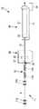
図1は、本発明による鋼棒の塗装装置10の一実施形態の構成を示している。
図1において、鋼棒の塗装装置10は、搬送手段11と、加熱手段12と、塗装手段20と、冷却手段30と、から構成されている。Hereinafter, the present invention will be described in detail based on the embodiments shown in the drawings.
FIG. 1 shows the configuration of an embodiment of a steel
In FIG. 1, a steel
搬送手段11は、図示の場合、搬送すべき鋼棒15を上下から挟み込んで、所定速度で回転駆動される複数対の駆動ローラ11aから構成されており、鋼棒15を通路Pに沿って軸方向に搬送する。これにより、例えば10mの定尺に切断された鋼棒15が連続的にまたは間欠的に所定速度、例えば33mm/秒で搬送される。 In the illustrated case, the
加熱手段12は、図示の場合、通路P上で所定間隔に配置された二つの誘導加熱コイル12a,12bから構成されている。これらの誘導加熱コイル12a,12bは、それぞれ多巻されており、それぞれ図示しない所定出力・周波数から成る誘導加熱電源に接続されている。鋼棒15は、上記搬送手段11により通路Pを所定速度で搬送されて加熱手段12の通過時に表面加熱され、所定の表面温度、即ち塗布すべき粉体塗料の分解温度以下の温度、例えば270℃程度の温度まで加熱される。 In the illustrated case, the heating means 12 is composed of two
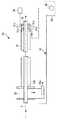
図2は図1の鋼棒の塗装装置10における塗装手段20の構成を示す概略断面図、図3は図1の鋼棒の塗装装置10における塗装手段20の支持部材22を示す部分拡大斜視図で、図4は図3の支持部材22の断面図である。
図2〜図4に示すように、塗装手段20は、チャンバー21と、支持部材22と、噴射管23と、塗料供給源24と、塗料回収装置25と、から構成されている。2 is a schematic cross-sectional view showing the configuration of the coating means 20 in the steel
As shown in FIGS. 2 to 4, the coating means 20 includes a
チャンバー21は内部が常圧雰囲気になっており、鋼棒15の通路P上にそれぞれ入口21a及び出口21bを備えている。
これらの入口21a及び出口21bには、それぞれチャンバー21の中心に向かって通路Pに沿って支持部材22の手前まで延びる保護管21c,21dが設けられている。The
These
保護管21c,21dは、それぞれ内側を鋼棒15が通路Pを通過し得るように通路Pを包囲しており、入口21a及び出口21bに対して気密的に取り付けられている。さらに、チャンバー21の入口21aの手前(上流側)には、図1に示すように、受けローラ26が設けられている。受けローラ26は接地(アース)されている。 The
受けローラ26は、その上方周面により搬送手段11によって加熱手段12を介して搬送されてくる鋼棒15を支持し回転することにより、鋼棒15をチャンバー21内に送り込む。 The
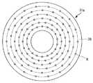
支持部材22は、チャンバー21の内部の中心付近に配置され、鋼棒15の通路Pの中心軸と同心の中空円筒状に形成されている。支持部材22は、図3及び図4に示すように、支持棒22aによりチャンバー21に対して保持されている。 The
支持部材22は、その周面に複数組、図示の場合、二組の支持孔22b,22cと、抜き孔22dと、を有している。一組の支持孔22bは、それぞれ同じ半径dを有しており、図4に示すように、中心軸Oに関して等角度間隔に、図示の場合、30度間隔で配置された12個の支持孔が、中心軸Oに沿って前後にずれて配置されている。即ち、支持孔22bは、鋼棒15の通路Pに対して前後にずれた二段に配置されている。 The
他の組の支持孔22cは、中心軸Oに関して等角度間隔に配置されていると共に、上述した組の支持孔22bとは異なる直径を有している。 The other set of
これにより、各組の支持孔22b,22cはそれぞれ中心軸Oに関して規則性をもって配置されている。 Thereby, the support holes 22b and 22c of each set are arranged with regularity with respect to the central axis O, respectively.
抜き孔22dは、支持部材22の支持孔22bのない領域に設けられており、支持部材22自体の重量を軽くすると共に、支持部材22への粉体塗料の付着量を低減するものである。 The
噴射管23は、フッ素樹脂等からなる中空管状の噴射ガンとして構成されており、塗料は中空管状の管璧との摩擦によって帯電する。図示の場合には、噴射管23のそれぞれ先端が、通路Pの中心にほぼ垂直に向くように一つの組の支持孔22bに支持されている。
なお、粉体塗料の噴射流量に応じて、異なる直径を有する噴射管23が、対応する直径の支持孔22cに支持されるようにしてもよい。各噴射管23は、図4に示すように、その他端が塗料供給源24に接続されている。The
Note that the
各噴射管23は、図4に示すように、その他端が塗料供給源24に接続されている。
これにより、各噴射管23は支持部材22の中心軸Oに関して規則性をもって配置されることになり、塗料供給源24から供給される粉体塗料を支持部材22の中心付近の通路Pに向かって均等に噴射する。
なお、各噴射管23の一端は、帯電噴射ガンとして構成されていてもよい。As shown in FIG. 4, the other end of each
As a result, the
Note that one end of each
塗料供給源24は公知の構成であって、圧縮空気等を利用して例えばエポキシ系の粉体塗料を所定の例えば30g/分の流量で各噴射管23に対して供給する。 The coating
塗料回収装置25は、チャンバー21の底部に配置されたスクリューコンベア25aと、チャンバー21の入口21a及び出口21bに設けられた押し込みノズル25b,25cと、チャンバー21の底部の吸引口21eから粉体塗料を吸引する吸引手段25dと、
吸引手段25dから粉体塗料を吸引して双方の押し込みノズル25b,25cに供給する噴出手段25eと、から構成されている。吸引手段25dとしては、サイクロン式回収装置を用いることができる。噴出手段25eとしては、ブロアーを用いることができる。The
It comprises spraying means 25e that sucks the powder paint from suction means 25d and supplies it to both pushing
スクリューコンベア25aはモータ25fにより駆動され、チャンバー21の底部に堆積した粉体塗料を吸引口21eに導く。 The
押し込みノズル25b,25cは、チャンバー21の入口21a及び出口21bから保護管21c,21d内に粉体塗料を吹き込むことにより、チャンバー21内に回収した粉体塗料を再供給すると共に、チャンバー21内から各保護管21c,21d内を通って外側に出ようとする粉体塗料をチャンバー21内に押し戻す。 The push-in
これにより、チャンバー21の入口21a及び出口21bからの粉体塗料の流出が防止されると共に、チャンバー21内における粉体塗料の流れが一定に保持される。 This prevents the powder paint from flowing out from the
サイクロン式回収装置25dは、チャンバー21内に堆積した粉体塗料を吸引口21eから吸引して回収する。ブロアー25eは、サイクロン式回収装置25d内に回収された粉体塗料の一部を各押し込みノズル25b,25cに供給する。なお、図示の場合、ブロアー25eにより供給される粉体塗料の一部は、サイクロン式回収装置25dに戻される。 The
図5は図1の塗装装置10における冷却手段30の構成を示す概略断面図である。
図5に示すように、冷却手段30は、塗装手段20に隣接して、鋼棒15の通路Pに沿って配置された樋型の冷却槽31と、冷却槽31の上流側に配置された排水部32と、ドレーンパン33と、ドレーンパン33の一側に設けられた貯水槽34と、給水ポンプ35と、圧縮空気源36と、から構成されている。FIG. 5 is a schematic sectional view showing the configuration of the cooling means 30 in the
As shown in FIG. 5, the cooling means 30 is arranged adjacent to the painting means 20, in a bowl-shaped
冷却槽31は、密閉式に構成されており、鋼棒15の搬送方向の下流側に設けられた給水口31aを介して給水ポンプ35によって貯水槽34から給水されることで上流側に向かって水流が形成される。
ここで、給水口31aは、冷却槽31内で上流側に向かって例えば45度だけ傾斜して配置されている。これにより、給水口31aから冷却槽31内に放出される水流が上流側に進む。The
Here, the
給水口31aの具体例について説明する。
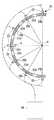
図6は図5の冷却手段30の給水口31aの概略断面図であり、図7は図6の給水口31aのA−A方向に沿った平面図である。
図6及び7に示すように、給水口31aは円錐状冷却器38から構成されている。円錐状冷却器38において、鋼棒15の通路となる搬送軸線Pの上部及び下部には、それぞれ、冷却水供給配管38aと給気口31dとが配設されている。A specific example of the
FIG. 6 is a schematic cross-sectional view of the
As shown in FIGS. 6 and 7, the
円錐状冷却器38は、冷却槽31内で入口(上流)側から軸方向、つまり鋼棒15の搬送軸線Pに対して所定の角度の傾斜面を有している。この角度(θ)が好ましくは45〜75°である。複数の冷却水噴射孔Hが、円錐状冷却器38の傾斜面に対して直角となるように穿孔されている。この円錐状冷却器38の中心には、被冷却物である表面に樹脂を塗布した鋼棒15の直径に対応し、かつ、被冷却物を通過させる穴が設けられており、被冷却物の通路となる。このため、円錐状冷却器38は、表面に樹脂が塗布された鋼棒15の円周方向から冷却することができる。
これにより、円錐状冷却器38から冷却槽31内に噴射される水流Wは上流側に向かって進む。つまり、冷却水は鋼棒15の搬送方向に対して対向して流れる。The
Thereby, the water flow W injected into the
冷却手段30で冷却される被冷却物は、加熱した鋼棒15の表面に樹脂を塗布したものであるので、被冷却物に直接冷却水を噴射して冷却した場合、剥離等の不具合を起こすことがあり得るので、冷却水を被冷却物の表面に沿って被冷却物の出口31c側から乱流とならずに整流として流して冷却することが好ましい。 Since the object to be cooled that is cooled by the cooling means 30 is obtained by applying a resin to the surface of the
加熱した鋼棒15の表面に樹脂を塗布して冷却した場合、鋼棒15の表面に塗付した樹脂の剥離等の不具合が生起しないように、円錐状冷却器38の傾斜面の角度θを45〜75°としている。角度が45°未満では、冷却水が乱流となり易く樹脂の剥離が生じ好ましくない。逆に、角度が75°を越えると、冷却効果が低下するので好ましくない。また、円錐状冷却器38の傾斜面の角度は、被冷却物に対して60°以上70°以下の範囲がより好ましいことが分かった。 When the resin is applied to the surface of the
冷却槽31は、その鋼棒15の通路P上に入口31b,出口31cを有している。ここで、冷却槽31の下流側の出口31cに隣接して給気口31dが設けられている。圧縮空気源36から送出される圧縮空気により、出口31cから鋼棒15と共に付着して漏れ出す冷却水を冷却槽31へ一部戻すと同時に、ドレーンパン33内に落とすことで、冷却槽31の出口31cからの冷却水の排出が阻止される。 The
ここで、圧縮空気源36から給気口31dを介して冷却槽31へ圧縮空気を送出する目的は、鋼棒15に付着して漏れてくる冷却水を冷却槽31外部へ漏れないように、圧縮空気でドレーンパン33上に落とすことが主であり、漏れてくる冷却水の一部を出口31c方向へ戻ることも考慮している。このため、圧縮空気の流量や圧力は、冷却槽31内の水流が整流となるように、整流に影響の無い範囲とすることが好ましい。 Here, the purpose of sending the compressed air from the compressed
これらの操作により、冷却槽31内において、冷却水が水密、つまり満杯な状態で冷却槽31内を満たしている。鋼棒15は、軸方向の下流側から上流側に流れる乱流ではなく整流状態の冷却水で冷却されるので、鋼棒15の表面に塗布された被膜に影響を与えずに被膜された鋼棒15が冷却される。 By these operations, the cooling water is filled in the
排水部32は、上方が開放した縦樋として構成されており、冷却槽31の入口31bから排出された冷却水を受けて、排水口32aからドレーンパン33内に排出する。ドレーンパン33は、冷却槽31全体の下方に配置されており、排水部32及び冷却槽31の出口31cから排出された冷却水を受けて、貯水槽34に導くように形成されている。 The
貯水槽34には、冷却槽31に供給される冷却水が貯蔵されている。冷却水は、好ましくは例えばチラー等の図示しない冷却槽31用の冷却部により、その温度が例えば5℃に保持されている。 The
本発明の実施形態による鋼棒の塗装装置10は以上のように構成されており、本発明による塗装方法に基づいて、以下のように動作する。
先ず、前処理された鋼棒15は、順次に搬送手段11により、連続的または間欠的に通路Pを所定速度で搬送される。The steel
First, the pretreated
通路Pを搬送される鋼棒15は加熱手段12内に導かれ、二つの誘導加熱コイル12a,12bにより表面加熱されて、所定の表面温度に予熱される。
続いて、鋼棒15は、受けローラ26を介して塗装手段20のチャンバー21の入口21aから保護管21cを通ってチャンバー21内に導入される。The
Subsequently, the
チャンバー21内で、鋼棒15は、所定速度で通過する際に保護管21c,21dの間の区間だけチャンバー21内に露出して、環状の支持部材22により支持された複数個の噴射管23から粉体塗料が噴射されることで塗装される。その際、鋼棒15の上面へのチャンバー21内に浮遊する粉体塗料の堆積が、保護管21c,21dにより阻止される。従って、複数個の噴射管23が環状に規則的に配置されていることと相まって、鋼棒15は、その表面全体に亘って均等の厚さで塗装膜が形成されることができる。 In the
さらに、噴射管23の内径及び個数そして塗布すべき粉体塗料の流量が適宜に選定されることにより、塗装膜ができるだけ薄く形成される。
その後、下流側に搬送される鋼棒15は、塗装手段20のチャンバー21の保護管21dを通って出口21bから搬出される。Furthermore, the coating film is formed as thin as possible by appropriately selecting the inner diameter and number of the
Thereafter, the
次に、塗装手段20から下流側に搬送される鋼棒15は、冷却手段30の排水部32から冷却槽31内に進入し、冷却槽31内で冷却水中に浸漬されることで冷却される。
その後、下流側に搬送される鋼棒15は、冷却槽31の出口31cから搬出される。Next, the
Thereafter, the
冷却槽31から入口31bと鋼棒15の間の間隙を通って排水部32内に排水された冷却水は、ドレーンパン33を通って貯水槽34に戻され、冷却された後、給水ポンプ35により再び給水口31aから冷却槽31内に循環される。 The cooling water drained into the
また、冷却槽31の出口31cでは、冷却槽31内に向かって給気口31dから圧縮空気が給気されているので、出口31cと鋼棒15との間の間隙から排出されようとする冷却水がこの圧縮空気により押し戻される。従って、冷却槽31の出口31cからの冷却水の洩れは生じない。 Further, at the
このようにして、搬送手段11により搬送される鋼棒15は、受けローラ26を介して塗装手段20のチャンバー21内に導入された後は、その表面が何にも触れることなく冷却手段30により冷却され、粉体塗料による塗装膜が硬化される。従って、冷却手段30から排出された鋼棒15は、図示しない第二の搬送手段により搬送されても、塗装膜が傷ついたり鋼棒15の表面から剥がれてしまったりすることはない。 Thus, after the
ところで、塗装手段20のチャンバー21内に浮遊する粉体塗料は、重力により落下して、チャンバー21の底部に堆積する。チャンバー21の底部に堆積した粉体塗料は、スクリューコンベア25aにより吸引口21eに導かれる。その際、チャンバー21の底部に堆積した粉体塗料が固まったとしても、スクリューコンベア25aの駆動により、固まった粉体塗料が崩れて容易に吸引口21eに導かれることになる。
そして、吸引口21eに導かれた粉体塗料は、サイクロン式回収装置25dにより吸引される。By the way, the powder coating material floating in the
Then, the powder coating material guided to the
サイクロン式回収装置25dに吸引され回収された粉体塗料は、その一部がブロアー25eにより押し込みノズル25b,25cからチャンバー21の入口21a及び出口21bに設けられた保護管21c,21d内に噴射される。
これにより、回収された粉体塗料が再びチャンバー21内に供給されると共に、チャンバー21内から保護管21c,21dを通ってチャンバー21から外部に出ようとする粉体塗料がチャンバー21内に押し戻される。従って、チャンバー21内に浮遊する粉体塗料は、保護管21c,21dが存在することにより、入口21a,出口21bからチャンバー21の外側に漏出しにくくなっていることもあって、入口21a及び出口21bからの粉体塗料の漏出が確実に阻止される。Part of the powder paint sucked and collected by the cyclone
As a result, the recovered powder coating material is supplied again into the
このようにして、塗料回収装置25によって、チャンバー21内で堆積した粉体粒子が回収され、再びチャンバー21内に供給されて再利用されると共に、チャンバー21内に浮遊する粉体塗料が入口21a及び出口21bからチャンバー21の外側に漏出することがないので、粉体塗料の利用効率が向上し、且つ周囲に対する粉体塗料の飛散即ち周囲環境の粉体塗料による汚染が確実に防止される。 In this way, the powder particles accumulated in the
本発明はその趣旨を逸脱しない範囲において様々な形態で実施することができる。
例えば、上述した実施形態においては、鋼棒15の予熱は、二つの誘導加熱コイル12a,12bを備えた加熱手段12により行なわれているが、これに限らず、他の任意の形式の加熱手段12が使用されてもよいことは明らかである。The present invention can be implemented in various forms without departing from the spirit of the present invention.
For example, in the above-described embodiment, the preheating of the
上述した実施形態においては、鋼棒15の表面に粉体塗料を付着させるために、支持部材22を備えた塗装手段20が備えられているが、これに限らず、鋼棒15を塗装することができれば、任意の構成の塗装手段20を使用することも可能である。 In the above-described embodiment, the coating means 20 including the
さらに、上述した実施形態においては、塗装後の鋼棒15を冷却するために、冷却手段30が備えられているが、これに限らず、鋼棒15を冷却することができれば、任意の構成の冷却手段30を使用することも可能である。 Furthermore, in the above-described embodiment, the cooling means 30 is provided to cool the
以下、本発明による鋼棒の塗装装置10の具体的な実施例について詳細に説明する。
鋼棒の塗装装置10を使用し、鋼棒15にエポキシ樹脂からなる粉体塗料(大日本塗料社製)を塗装した。鋼棒15としては、平均外径32mmの異形鉄筋(ネジボン(高周波熱錬株式会社の登録商標)、D32)を用いた。塗装前の前処理として、鋼棒15にはショットブラスト等による表面清浄化を施した。鋼棒15の送り速度を30mm/秒とした。周波数が25kHzで出力が22kWの誘導加熱装置を加熱手段12として用い、鋼棒15を200〜250℃に加熱した。鋼棒15の熱処理状態の一例を示すと、鋼棒15のチャンバー21の入口21aの表面温度は240℃であり、チャンバー21の出口21bの温度は235℃であり、その後で鋼棒15を冷却槽31において水温5℃の冷却水で冷却し、45℃とした。
なお、上記実験例において、塗工後の鋼棒15にピンホールは認められなかった。Hereinafter, specific examples of the steel
Using a steel
In the experimental example, no pinhole was observed in the
(比較例)
実施例に対する比較例として、保護管21c、21dを設置しないチャンバー21を使用し、他は同じ条件によってエポキシ塗料を鋼棒15に塗装した。(Comparative example)
As a comparative example with respect to the embodiment, the
表1に、実施例及び比較例のエポキシ塗料の塗膜厚さ(μm)を測定した結果を示す。塗膜の厚さは電磁式厚膜計(ケット科学研究所社製、LE−300J)で測定した。
表1の測定値は、実施例及び比較例の鋼棒15の平滑部、節の低部(節底と呼ぶ)、節の頂部(節頂と呼ぶ)における塗膜の厚さを示している。実施例の場合は、鋼棒15を4本測定した場合の塗膜厚さとその平均値を示し、比較例の場合は、鋼棒15が3本について測定した塗膜厚さとその平均値を示している。 The measured values in Table 1 indicate the thickness of the coating film in the smooth portion, the lower portion of the node (referred to as the node bottom), and the top of the node (referred to as the node top) of the
実施例の鋼棒15の場合、平滑部上面の塗膜厚さは275μm,298μm,304μm,290μmで、平均厚さは292μmであった。平滑部下面の塗膜厚さは304μm,296μm,309μm,281μmで、平均厚さは298μmであった。節底の塗膜厚さは260μm,271μm,276μm,266μmで、平均厚さは268μmであった。節頂の塗膜厚さは268μm,258μm,242μm,284μmで、平均厚さは263μmであった。 In the case of the
比較例の鋼棒15の場合、平滑部の塗膜厚さは345μm,346μm,313μmで、平均厚さは334μmであった。節底の塗膜厚さは268μm,278μm,293μmで、平均厚さは280μmであった。節頂の塗膜厚さは407μm,422μm,435μmで、平均厚さは421μmであった。 In the case of the
表1から明らかなように、実施例の鋼棒15の塗膜における平滑部の上面及び下面の塗膜厚さは、それぞれ、292μm,298μmであり、殆ど差がないことが分かる。さらに、実施例の鋼棒15の平滑部における上面及び下面の塗膜厚さは、比較例の場合よりも約30μm薄くなっていることが分かる。実施例の鋼棒15では、節底と節頂の塗膜を平均厚さで比較した場合、差が5μm程度である。
一方、比較例の場合、節底と節頂の塗膜を平均厚さで比較した場合、差が140μm程度と非常に大きいことが分かる。これから、実施例の鋼棒15の塗膜は、比較例の場合よりも塗膜が薄く、かつ、より均一に塗付されていることが判明した。As is apparent from Table 1, the coating thicknesses of the upper and lower surfaces of the smooth portion in the coating of the
On the other hand, in the case of the comparative example, it is found that when the coatings on the bottom and the top of the joint are compared with the average thickness, the difference is as large as about 140 μm. From this, it was found that the coating film of the
実施例の鋼棒15の塗工には、保護管21c、21dを設置したチャンバー21を使用しており、塗工に保護管21c、21dを設置しない比較例と比較すると、粉体塗料が鋼棒15の表面全体に亘ってより一層均等の厚さとすることができた。保護管21c、21dをチャンバー21内に設けることによって、塗膜の厚さを均等にできることが分かる。 The coating of the
実施例の塗工した鋼棒15を、土木学会基準「エポキシ樹脂塗装鉄筋の曲げ試験方法(JSCE−E515−2003)」によって曲げ試験を実施した。
曲げ試験条件を以下に示す。
曲げ試験条件
試験本数 :各水準 6本(加熱温度200℃、240℃)
曲げ内半径:3D、4D(ここで、Dは鋼棒15の直径であり、試験では32mmである。)
曲げ角度 :90°
試験温度 :室温The coated
The bending test conditions are shown below.
Bending test conditions Number of test: 6 for each level (heating temperature 200 ° C, 240 ° C)
Bending radius: 3D, 4D (where D is the diameter of the
Bending angle: 90 °
Test temperature: Room temperature
曲げ試験における割れ発生率は、下記(1)式で求めた。
P=A/N×100(%) (1)
ここで、Pは割れ発生率(%)、Aは割れの発生した供試体数、Nは全供試体測定数である。The crack occurrence rate in the bending test was determined by the following equation (1).
P = A / N × 100 (%) (1)
Here, P is the crack occurrence rate (%), A is the number of specimens in which cracks occurred, and N is the number of all specimens measured.
曲げ試験において、曲げ内半径による差は見られなかった。鋼棒15の加熱温度を200℃とした場合、1〜2mm以下のクラックが33%発生した。鋼棒15の加熱温度が240℃の場合、割れは0%、発生しなかった。 In the bending test, no difference due to the bending inner radius was observed. When the heating temperature of the
以上述べたように、本発明によれば、簡単な構成により鋼棒15、特に異形鋼棒15の表面に噴射した粉体塗料が散逸しないようにした、極めて優れた鋼棒の塗装装置10が提供される。 As described above, according to the present invention, there is provided an extremely excellent steel
10:鋼棒の塗装装置
11:搬送手段
11a:駆動ローラ
12:加熱手段
12a,12b:誘導加熱コイル
15:鋼棒
20:塗装手段
21:チャンバー
21a:入口
21b:出口
21c,21d:保護管
21e:吸引口
22:支持部材
22a:支持棒
22b,22c:支持孔
22d:抜き孔
23:噴射管
24:塗料供給源
25:塗料回収装置
25a:スクリューコンベア
25b,25c:押し込みノズル
25d:サイクロン式回収装置
25e:ブロアー
25f:モータ
26:受けローラ
30:冷却手段
31:冷却槽
31a:給水口
31b:入口
31c:出口
31d:給気口
32:排水部
32a:排水口
33:ドレーンパン
34:貯水槽
35:給水ポンプ
36:圧縮空気源
38:円錐状冷却器
38a:冷却水供給配管DESCRIPTION OF SYMBOLS 10: Steel bar coating apparatus 11: Conveyance means 11a: Driving roller 12: Heating means 12a, 12b: Induction heating coil 15: Steel bar 20: Coating means 21:
Claims (4)
Translated fromJapanese上記塗装手段が、上記搬送手段により搬送される鋼棒の通路に入口及び出口を有するチャンバーと、上記チャンバー内で上記通路を搬送される鋼棒の表面に粉体塗料を噴射する複数個の噴射管と、各噴射管に粉体塗料を供給する塗料供給源と、上記チャンバー内の粉体塗料を回収する塗料回収装置と、を備えており、
上記塗料回収装置が、上記チャンバーの底部に堆積した粉体塗料を吸引する吸引手段と、上記吸引手段により吸引された粉体塗料の少なくとも一部を上記チャンバーの入口及び出口から内部に噴出させる噴出手段と、
を備えていることを特徴とする、鋼棒の塗装装置。Conveying means for conveying the steel rod in the axial direction, heating means for preheating the steel rod conveyed by the conveying means, coating means for electrifying and spraying powder coating material on the surface of the steel rod preheated by the heating means, A steel bar coating apparatus comprising: cooling means for water-cooling a steel bar on which body paint is charged and jetted;
The coating means has a chamber having an inlet and an outlet in a passage of a steel rod conveyed by the conveying means, and a plurality of injections for injecting powder paint onto the surface of the steel rod conveyed in the passage in the chamber A pipe, a paint supply source for supplying powder paint to each spray pipe, and a paint recovery device for recovering the powder paint in the chamber,
The paint recovery device sucks the powder paint deposited on the bottom of the chamber, and ejects at least part of the powder paint sucked by the suction means from the inlet and the outlet of the chamber to the inside Means,
A steel bar coating apparatus, comprising:
Priority Applications (1)
| Application Number | Priority Date | Filing Date | Title |
|---|---|---|---|
| JP2008167986AJP5245089B2 (en) | 2008-06-26 | 2008-06-26 | Steel bar coating equipment |
Applications Claiming Priority (1)
| Application Number | Priority Date | Filing Date | Title |
|---|---|---|---|
| JP2008167986AJP5245089B2 (en) | 2008-06-26 | 2008-06-26 | Steel bar coating equipment |
Publications (2)
| Publication Number | Publication Date |
|---|---|
| JP2010005535A JP2010005535A (en) | 2010-01-14 |
| JP5245089B2true JP5245089B2 (en) | 2013-07-24 |
Family
ID=41586614
Family Applications (1)
| Application Number | Title | Priority Date | Filing Date |
|---|---|---|---|
| JP2008167986AActiveJP5245089B2 (en) | 2008-06-26 | 2008-06-26 | Steel bar coating equipment |
Country Status (1)
| Country | Link |
|---|---|
| JP (1) | JP5245089B2 (en) |
Families Citing this family (3)
| Publication number | Priority date | Publication date | Assignee | Title |
|---|---|---|---|---|
| KR101192604B1 (en)* | 2011-08-19 | 2012-10-18 | 웅 방 | Epoxy coating rock bolt and manufacture method |
| CN104174667A (en)* | 2013-05-23 | 2014-12-03 | 宜兴市新芳铜厂有限公司 | Copper rod cleaning system |
| CN111195582B (en)* | 2020-03-09 | 2021-04-13 | 宁波永恩半导体科技有限公司 | Preparation process of semiconductor electronic element |
Family Cites Families (8)
| Publication number | Priority date | Publication date | Assignee | Title |
|---|---|---|---|---|
| JPS5142596B1 (en)* | 1971-09-27 | 1976-11-16 | ||
| JPS4898552U (en)* | 1972-02-25 | 1973-11-21 | ||
| JPS58120034U (en)* | 1982-02-10 | 1983-08-16 | 大日本印刷株式会社 | dusting equipment |
| DE3412275C2 (en)* | 1984-04-02 | 1986-10-30 | Ransburg-Gema AG, St. Gallen | Powder coating booth |
| JPS61291079A (en)* | 1985-06-15 | 1986-12-20 | Nakayama Seikosho:Kk | Online painting system for rolled steel materials |
| JPS63221868A (en)* | 1987-03-12 | 1988-09-14 | Hokkai Koki Kk | Method and apparatus for continuously applying powdery resin |
| JPH0685051U (en)* | 1993-05-27 | 1994-12-06 | 株式会社飯田製作所 | Powder coating equipment |
| JPH07328494A (en)* | 1994-06-01 | 1995-12-19 | Asahi Sanac Kk | Electrostatic coating equipment for powder coatings |
- 2008
- 2008-06-26JPJP2008167986Apatent/JP5245089B2/enactiveActive
Also Published As
| Publication number | Publication date |
|---|---|
| JP2010005535A (en) | 2010-01-14 |
Similar Documents
| Publication | Publication Date | Title |
|---|---|---|
| JP5321877B2 (en) | Steel bar coating apparatus and method | |
| US3016875A (en) | Apparatus for coating pipe | |
| US3620813A (en) | Method of treating workpieces in a treating fluid | |
| KR101880072B1 (en) | Device and method for coating pipe including internal shot blasting equipment and coating pipe | |
| KR100898838B1 (en) | Apparatus and method for coating 3-layer polyethylene and polyurea on steel pipe | |
| JP5305192B2 (en) | Steel bar coating equipment | |
| JP5245089B2 (en) | Steel bar coating equipment | |
| JP2021527565A (en) | Improved methods and equipment for atmospheric plasma jet coating deposition on substrates | |
| CN103108725B (en) | Method and apparatus for removing ceramic coatings by solid CO2 sparging | |
| US20100294316A1 (en) | Tube Cleaning Device | |
| TW201416496A (en) | Surface treating apparatus | |
| TWI603784B (en) | Film formation apparatus | |
| JP2021522081A (en) | Equipment and methods for surface treatment of materials | |
| KR101267033B1 (en) | Inner coating steel pipe with epoxy powder coating and a method of manufacturing the same | |
| KR101267035B1 (en) | Inner coating steel pipe with epoxy powder coating | |
| JP2004358312A (en) | Washing method for coating hanger | |
| KR101267036B1 (en) | Inner coating steel pipe with epoxy powder coating manufacturing equipment | |
| CN203044569U (en) | On-line external degreasing steel pipe cleaning equipment | |
| KR101669177B1 (en) | A method for treating rolled steel for a general structure and facilities therefor | |
| JP6156062B2 (en) | Powder coating apparatus and powder coating method | |
| JP2016059892A (en) | Coating masking method | |
| US6613237B2 (en) | Apparatus and method for removing matter on a fluid surface of a tank | |
| JP2009148651A (en) | Cleaning method and cleaning apparatus for drain pipe | |
| KR20170071025A (en) | Coating apparatus for coating inside and outside of steel pipe and a coating method thereof | |
| JPH06122979A (en) | Pretreatment method for resin coated steel pipe |
Legal Events
| Date | Code | Title | Description |
|---|---|---|---|
| A621 | Written request for application examination | Free format text:JAPANESE INTERMEDIATE CODE: A621 Effective date:20110228 | |
| A977 | Report on retrieval | Free format text:JAPANESE INTERMEDIATE CODE: A971007 Effective date:20130214 | |
| TRDD | Decision of grant or rejection written | ||
| A01 | Written decision to grant a patent or to grant a registration (utility model) | Free format text:JAPANESE INTERMEDIATE CODE: A01 Effective date:20130226 | |
| A61 | First payment of annual fees (during grant procedure) | Free format text:JAPANESE INTERMEDIATE CODE: A61 Effective date:20130314 | |
| R150 | Certificate of patent or registration of utility model | Free format text:JAPANESE INTERMEDIATE CODE: R150 | |
| FPAY | Renewal fee payment (event date is renewal date of database) | Free format text:PAYMENT UNTIL: 20160419 Year of fee payment:3 | |
| R250 | Receipt of annual fees | Free format text:JAPANESE INTERMEDIATE CODE: R250 | |
| R250 | Receipt of annual fees | Free format text:JAPANESE INTERMEDIATE CODE: R250 | |
| R250 | Receipt of annual fees | Free format text:JAPANESE INTERMEDIATE CODE: R250 | |
| R250 | Receipt of annual fees | Free format text:JAPANESE INTERMEDIATE CODE: R250 |