JP5244201B2 - Ultrasonic probe and ultrasonic diagnostic apparatus - Google Patents
Ultrasonic probe and ultrasonic diagnostic apparatusDownload PDFInfo
- Publication number
- JP5244201B2 JP5244201B2JP2011012773AJP2011012773AJP5244201B2JP 5244201 B2JP5244201 B2JP 5244201B2JP 2011012773 AJP2011012773 AJP 2011012773AJP 2011012773 AJP2011012773 AJP 2011012773AJP 5244201 B2JP5244201 B2JP 5244201B2
- Authority
- JP
- Japan
- Prior art keywords
- channel
- sub
- die elements
- ultrasonic
- channels
- Prior art date
- Legal status (The legal status is an assumption and is not a legal conclusion. Google has not performed a legal analysis and makes no representation as to the accuracy of the status listed.)
- Expired - Fee Related
Links
Images


Classifications
- A—HUMAN NECESSITIES
- A61—MEDICAL OR VETERINARY SCIENCE; HYGIENE
- A61B—DIAGNOSIS; SURGERY; IDENTIFICATION
- A61B8/00—Diagnosis using ultrasonic, sonic or infrasonic waves
- A61B8/44—Constructional features of the ultrasonic, sonic or infrasonic diagnostic device
- A61B8/4483—Constructional features of the ultrasonic, sonic or infrasonic diagnostic device characterised by features of the ultrasound transducer
- B—PERFORMING OPERATIONS; TRANSPORTING
- B06—GENERATING OR TRANSMITTING MECHANICAL VIBRATIONS IN GENERAL
- B06B—METHODS OR APPARATUS FOR GENERATING OR TRANSMITTING MECHANICAL VIBRATIONS OF INFRASONIC, SONIC, OR ULTRASONIC FREQUENCY, e.g. FOR PERFORMING MECHANICAL WORK IN GENERAL
- B06B1/00—Methods or apparatus for generating mechanical vibrations of infrasonic, sonic, or ultrasonic frequency
- B06B1/02—Methods or apparatus for generating mechanical vibrations of infrasonic, sonic, or ultrasonic frequency making use of electrical energy
- B06B1/06—Methods or apparatus for generating mechanical vibrations of infrasonic, sonic, or ultrasonic frequency making use of electrical energy operating with piezoelectric effect or with electrostriction
- B06B1/0607—Methods or apparatus for generating mechanical vibrations of infrasonic, sonic, or ultrasonic frequency making use of electrical energy operating with piezoelectric effect or with electrostriction using multiple elements
- B06B1/0622—Methods or apparatus for generating mechanical vibrations of infrasonic, sonic, or ultrasonic frequency making use of electrical energy operating with piezoelectric effect or with electrostriction using multiple elements on one surface
- B06B1/064—Methods or apparatus for generating mechanical vibrations of infrasonic, sonic, or ultrasonic frequency making use of electrical energy operating with piezoelectric effect or with electrostriction using multiple elements on one surface with multiple active layers
- G—PHYSICS
- G01—MEASURING; TESTING
- G01S—RADIO DIRECTION-FINDING; RADIO NAVIGATION; DETERMINING DISTANCE OR VELOCITY BY USE OF RADIO WAVES; LOCATING OR PRESENCE-DETECTING BY USE OF THE REFLECTION OR RERADIATION OF RADIO WAVES; ANALOGOUS ARRANGEMENTS USING OTHER WAVES
- G01S15/00—Systems using the reflection or reradiation of acoustic waves, e.g. sonar systems
- G01S15/88—Sonar systems specially adapted for specific applications
- G01S15/89—Sonar systems specially adapted for specific applications for mapping or imaging
- G01S15/8906—Short-range imaging systems; Acoustic microscope systems using pulse-echo techniques
- G01S15/8909—Short-range imaging systems; Acoustic microscope systems using pulse-echo techniques using a static transducer configuration
- G01S15/8915—Short-range imaging systems; Acoustic microscope systems using pulse-echo techniques using a static transducer configuration using a transducer array
- G01S15/8927—Short-range imaging systems; Acoustic microscope systems using pulse-echo techniques using a static transducer configuration using a transducer array using simultaneously or sequentially two or more subarrays or subapertures
- G—PHYSICS
- G01—MEASURING; TESTING
- G01S—RADIO DIRECTION-FINDING; RADIO NAVIGATION; DETERMINING DISTANCE OR VELOCITY BY USE OF RADIO WAVES; LOCATING OR PRESENCE-DETECTING BY USE OF THE REFLECTION OR RERADIATION OF RADIO WAVES; ANALOGOUS ARRANGEMENTS USING OTHER WAVES
- G01S7/00—Details of systems according to groups G01S13/00, G01S15/00, G01S17/00
- G01S7/52—Details of systems according to groups G01S13/00, G01S15/00, G01S17/00 of systems according to group G01S15/00
- G01S7/52017—Details of systems according to groups G01S13/00, G01S15/00, G01S17/00 of systems according to group G01S15/00 particularly adapted to short-range imaging
- G01S7/52079—Constructional features
- G01S7/5208—Constructional features with integration of processing functions inside probe or scanhead
- G—PHYSICS
- G01—MEASURING; TESTING
- G01S—RADIO DIRECTION-FINDING; RADIO NAVIGATION; DETERMINING DISTANCE OR VELOCITY BY USE OF RADIO WAVES; LOCATING OR PRESENCE-DETECTING BY USE OF THE REFLECTION OR RERADIATION OF RADIO WAVES; ANALOGOUS ARRANGEMENTS USING OTHER WAVES
- G01S7/00—Details of systems according to groups G01S13/00, G01S15/00, G01S17/00
- G01S7/52—Details of systems according to groups G01S13/00, G01S15/00, G01S17/00 of systems according to group G01S15/00
- G01S7/52017—Details of systems according to groups G01S13/00, G01S15/00, G01S17/00 of systems according to group G01S15/00 particularly adapted to short-range imaging
- G01S7/52079—Constructional features
- G01S7/52082—Constructional features involving a modular construction, e.g. a computer with short range imaging equipment
- G—PHYSICS
- G10—MUSICAL INSTRUMENTS; ACOUSTICS
- G10K—SOUND-PRODUCING DEVICES; METHODS OR DEVICES FOR PROTECTING AGAINST, OR FOR DAMPING, NOISE OR OTHER ACOUSTIC WAVES IN GENERAL; ACOUSTICS NOT OTHERWISE PROVIDED FOR
- G10K11/00—Methods or devices for transmitting, conducting or directing sound in general; Methods or devices for protecting against, or for damping, noise or other acoustic waves in general
- G10K11/18—Methods or devices for transmitting, conducting or directing sound
- G10K11/26—Sound-focusing or directing, e.g. scanning
- G10K11/34—Sound-focusing or directing, e.g. scanning using electrical steering of transducer arrays, e.g. beam steering
- A—HUMAN NECESSITIES
- A61—MEDICAL OR VETERINARY SCIENCE; HYGIENE
- A61B—DIAGNOSIS; SURGERY; IDENTIFICATION
- A61B8/00—Diagnosis using ultrasonic, sonic or infrasonic waves
- A61B8/44—Constructional features of the ultrasonic, sonic or infrasonic diagnostic device
- A61B8/4438—Means for identifying the diagnostic device, e.g. barcodes
- A—HUMAN NECESSITIES
- A61—MEDICAL OR VETERINARY SCIENCE; HYGIENE
- A61B—DIAGNOSIS; SURGERY; IDENTIFICATION
- A61B8/00—Diagnosis using ultrasonic, sonic or infrasonic waves
- A61B8/44—Constructional features of the ultrasonic, sonic or infrasonic diagnostic device
- A61B8/4483—Constructional features of the ultrasonic, sonic or infrasonic diagnostic device characterised by features of the ultrasound transducer
- A61B8/4488—Constructional features of the ultrasonic, sonic or infrasonic diagnostic device characterised by features of the ultrasound transducer the transducer being a phased array
Landscapes
- Engineering & Computer Science (AREA)
- Physics & Mathematics (AREA)
- Radar, Positioning & Navigation (AREA)
- Remote Sensing (AREA)
- Acoustics & Sound (AREA)
- Health & Medical Sciences (AREA)
- Computer Networks & Wireless Communication (AREA)
- General Physics & Mathematics (AREA)
- Life Sciences & Earth Sciences (AREA)
- Nuclear Medicine, Radiotherapy & Molecular Imaging (AREA)
- Animal Behavior & Ethology (AREA)
- Gynecology & Obstetrics (AREA)
- Multimedia (AREA)
- Biophysics (AREA)
- Veterinary Medicine (AREA)
- Pathology (AREA)
- Radiology & Medical Imaging (AREA)
- Biomedical Technology (AREA)
- Heart & Thoracic Surgery (AREA)
- Medical Informatics (AREA)
- Molecular Biology (AREA)
- Surgery (AREA)
- Mechanical Engineering (AREA)
- General Health & Medical Sciences (AREA)
- Public Health (AREA)
- Computer Hardware Design (AREA)
- General Engineering & Computer Science (AREA)
- Ultra Sonic Daignosis Equipment (AREA)
- Investigating Or Analyzing Materials By The Use Of Ultrasonic Waves (AREA)
Description
Translated fromJapaneseこの発明は、超音波プローブおよび超音波診断装置に係り、特に、それぞれ複数のサブダイス素子が接続された複数のチャンネルを有する超音波プローブおよびこれを用いた超音波診断装置に関する。 The present invention relates to an ultrasonic probe and an ultrasonic diagnostic apparatus, and more particularly to an ultrasonic probe having a plurality of channels to which a plurality of sub-die elements are connected, and an ultrasonic diagnostic apparatus using the same.
従来から、医療分野において、超音波画像を利用した超音波診断装置が実用化されている。一般に、この種の超音波診断装置は、超音波振動子を内蔵した超音波プローブと、この超音波プローブに接続された装置本体とを有してしる。装置本体には内蔵された超音波送受信回路の処理能力に対応する超音波プローブが接続され、超音波送受信回路からの駆動信号に基づいて超音波プローブから被検体に向けて超音波を送信し、被検体からの超音波エコーを超音波プローブで受信して、その受信信号を装置本体の超音波送受信回路で受信すると共に装置本体において電気的に処理することにより超音波画像が生成される。 Conventionally, in the medical field, an ultrasonic diagnostic apparatus using an ultrasonic image has been put into practical use. In general, this type of ultrasonic diagnostic apparatus includes an ultrasonic probe having an ultrasonic transducer and a main body connected to the ultrasonic probe. An ultrasonic probe corresponding to the processing capability of the built-in ultrasonic transmission / reception circuit is connected to the apparatus body, and an ultrasonic wave is transmitted from the ultrasonic probe to the subject based on a drive signal from the ultrasonic transmission / reception circuit, An ultrasonic image is generated by receiving an ultrasonic echo from a subject with an ultrasonic probe, receiving the received signal with an ultrasonic transmission / reception circuit of the apparatus body, and electrically processing the received signal in the apparatus body.
近年、ベッドサイドや救急医療現場等に搬送して使用することができるポータブル型あるいは携帯型の超音波診断装置が開発されている。このような超音波診断装置は、操作性および利便性を追求すべく装置の小型化が要求され、これに伴って超音波送受信回路の規模自体も小さく、画質の低下を余儀なくされている。そこで、超音波診断装置を小型化すると共に画質の低下を抑制することが求められている。 In recent years, portable or portable ultrasonic diagnostic apparatuses that can be used by being transported to a bedside or emergency medical site have been developed. Such an ultrasonic diagnostic apparatus is required to be downsized in order to pursue operability and convenience, and accordingly, the scale of the ultrasonic transmission / reception circuit itself is small, and image quality is inevitably lowered. Therefore, there is a demand for downsizing the ultrasonic diagnostic apparatus and suppressing deterioration in image quality.
例えば、特許文献1には、携帯型の超音波ユニットをドッキング・カートにドッキングさせることによりドッキング・カートでデータ処理を行う超音波診断システムが開示されている。携帯型の超音波ユニットで生成された受信信号がドッキング・カートに供給され、ドッキング・カートの高いデータ処理能力で受信信号が処理された後、ドッキング・カートのディスプレイに高い解像度で超音波画像が表示される。 For example,
特許文献1のシステムでは、ドッキング・カートに携帯型の超音波ユニットをドッキングさせることで、携帯型の超音波ユニットが有する処理能力よりも高い能力で受信信号の処理を行うことができる。しかしながら、ドッキングされる携帯型の超音波ユニットのクラスに応じて超音波送受信回路の規模はそれぞれ異なるため、それぞれの超音波ユニットのクラスに対応した超音波プローブを複数備える必要がある。 In the system of
この発明は、このような従来の問題点を解消するためになされたもので、超音波送受信回路の規模の異なる診断装置本体に対応することができる超音波プローブを提供することを目的とする。
また、この発明は、このような超音波プローブを用いた超音波診断装置を提供することも目的としている。The present invention has been made to solve the above-described conventional problems, and an object of the present invention is to provide an ultrasonic probe capable of dealing with a diagnostic apparatus body having a different scale of an ultrasonic transmission / reception circuit.
Another object of the present invention is to provide an ultrasonic diagnostic apparatus using such an ultrasonic probe.
本発明に係る超音波プローブは、超音波の送受信を制御する装置本体に対し、装置本体から複数の信号線を介して伝送された駆動信号に基づいてアレイトランスジューサから超音波ビームを被検体に向けて送信し、被検体からの超音波エコーをアレイトランスジューサで受信して得られた受信信号を装置本体の複数の送受信回路に接続された複数の信号線を介して伝送する超音波プローブであって、アレイトランスジューサを構成する各トランスジューサが厚み振動以外の不要振動を抑えて超音波を送受信するように複数のサブダイス素子より構成され、より少ない送受信回路を有する装置本体に対応してチャンネル数を減少させる場合には各チャンネルを構成するサブダイス素子の数が増加するように複数のサブダイス素子の接続状態を切り換えると共にアレイトランスジューサを構成する複数のトランスジューサを複数の信号線のいずれかに対応付けて選択的に接続することにより複数の信号線のうち各チャンネルに接続されて駆動信号および受信信号を伝送する有効信号線を選択するチャンネル形成・接続部を備えたものである。An ultrasonic probe according to the present invention directs an ultrasonic beam from an array transducer to a subject based on a drive signal transmitted from the apparatus main body via a plurality of signal lines to an apparatus main body that controls transmission and reception of ultrasonic waves. An ultrasonic probe that transmits a reception signal obtained by receiving an ultrasonic echo from a subject with an array transducer viaa plurality of signal linesconnected to a plurality of transmission / reception circuits of the apparatus body. Each transducer constituting the array transducer is composed of a plurality of sub-die elements so as to transmit / receive ultrasonic waves while suppressing unnecessary vibration other than thickness vibration, and thenumber of channels is reduced corresponding to the apparatus main body having fewer transmission / reception circuits. switching the connection states of a plurality of sub die elementsso that the number of the sub die elements forming each channel is increased if In addition, the plurality of transducers constituting the array transducer are selectively connected in association with any of the plurality of signal lines, thereby being connected to each channel of the plurality of signal lines and effectively transmitting the drive signal and the reception signal. A channel forming / connecting section for selecting a signal line is provided.
ここで、前記チャンネル形成・接続部は、複数のサブダイス素子間の接続を選択することによりそれぞれ複数のサブダイス素子からなる複数のチャンネルを形成すると共に複数のチャンネルのうち2以上のチャンネルを同一の信号線に排他的に割り付けるためのチャンネル形成・接続スイッチを有することが好ましい。
また、前記チャンネル形成・接続部は、複数のサブダイス素子間の接続を選択することによりそれぞれ複数のサブダイス素子からなる複数のチャンネルを形成するための複数のスイッチを有するチャンネル形成部と、前記チャンネル形成部で形成された複数のチャンネルのうち2以上のチャンネルを同一の信号線に排他的に割り付けるための複数のスイッチを有するチャンネル接続部とを含み、複数の信号線のうち前記チャンネル接続部により各チャンネルと接続された信号線が前記有効信号線となるのが好ましい。Here, the channel formation / connection unit forms a plurality of channels each composed of a plurality of sub-die elements by selecting a connection between the plurality of sub-die elements, and two or more channels out of the plurality of channels have the same signal. It is preferable to have a channel forming / connecting switch for allocating exclusively to the line.
The channel forming / connecting section includes a channel forming section having a plurality of switches for forming a plurality of channels each composed of a plurality of sub die elements by selecting a connection between the plurality of sub die elements, and the channel forming section. And a channel connection unit having a plurality of switches for exclusively allocating two or more channels among the plurality of channels formed in the unit to the same signal line, and each of the plurality of signal lines by the channel connection unit The signal line connected to the channel is preferably the effective signal line.
また、前記チャンネル形成・接続部は、各チャンネルを構成するサブダイス素子数がそれぞれ同数となるように接続状態を切り換えることができる。 In addition, the channel forming / connecting section can switch the connection state so that the number of sub-die elements constituting each channel is the same.
また、本発明に係る超音波診断装置は、上記のいずれかに記載の超音波プローブと、それぞれ対応する前記有効信号線に接続される複数の送受信回路を有する少なくとも1台の装置本体とを有し、前記チャンネル形成・接続部による複数のサブダイス素子の接続状態の切り換えは、前記少なくとも1台の装置本体の有する送受信回路の総数に応じて行われるものである。 An ultrasonic diagnostic apparatus according to the present invention includes any one of the ultrasonic probes described above and at least one apparatus main body including a plurality of transmission / reception circuits connected to the corresponding effective signal lines. The switching of the connection states of the plurality of sub-die elements by the channel forming / connecting unit is performed in accordance with the total number of transmission / reception circuits included in the at least one apparatus main body.
この発明によれば、複数のサブダイス素子の接続状態を切り換えることにより各チャンネルを構成するサブダイス素子数を変更するので、超音波送受信回路の規模の異なる診断装置本体に超音波プローブを対応させることが可能となる。 According to the present invention, since the number of sub-die elements constituting each channel is changed by switching the connection state of a plurality of sub-die elements, the ultrasonic probe can be made to correspond to a diagnostic apparatus body having a different scale of the ultrasonic transmission / reception circuit. It becomes possible.
以下、この発明の実施形態を添付図面に基づいて説明する。
実施形態1
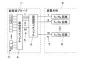
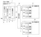
図1に、この発明の実施形態1に係る超音波診断装置の構成を示す。超音波診断装置は、超音波を送受信する超音波プローブ1と、超音波プローブ1に接続された装置本体2を備えている。Embodiments of the present invention will be described below with reference to the accompanying drawings.
FIG. 1 shows the configuration of an ultrasonic diagnostic apparatus according to
超音波プローブ1は、アレイ状に配列されたK個のサブダイス素子がそれぞれ所定数ずつ接続された複数のトランスジューサからなるアレイトランスジューサ3を有しており、それぞれのトランスジューサによりチャンネルが形成される。アレイトランスジューサ3には、K個のサブダイス素子間の接続を選択的に切り換えることによりそれぞれ複数のサブダイス素子からなる複数のチャンネルを形成するチャンネル形成部4が接続されている。チャンネル形成部4にはM本の入出力線5を介してチャンネル接続部6が接続され、このチャンネル接続部6に駆動信号および受信信号を伝送するためのN本の信号線7を有する接続ケーブルが接続されている。チャンネル接続部6は、マルチプレクサ(MUX)から構成され、入出力線5と信号線7との接続状態を切り換える。
装置本体2は、N個のTx/Rx(送受信)回路8を有しており、これらのTx/Rx回路8に接続ケーブルの信号線7がそれぞれ対応して接続されている。各Tx/Rx回路8は、それぞれの信号線7を介して超音波プローブ1の各チャンネルに送信信号を供給すると共に超音波プローブ1の各チャンネルで生成された受信信号を受信する。装置本体2は、Tx/Rx回路8で受信された受信信号に基づいて超音波画像を表す画像データを生成する。
なお、超音波プローブ1のサブダイス素子の個数Kはチャンネル接続部6とチャンネル形成部4とを接続する入出力線5の本数Mより多く設定され、入出力線5の本数Mは信号線7およびTx/Rx回路8の個数Nより多く設定されている。The
The apparatus
The number K of sub-die elements of the
図2に、超音波プローブ1に内蔵されたアレイトランスジューサ3の構成を示す。アレイトランスジューサ3を構成する各トランスジューサは、短冊状に分割されて複数のサブダイス素子を構成する圧電振動子9を有し、各圧電振動子9にはチャンネル毎に同一の電圧を印加するための電極10が設置され、その背面側には超音波による余分な振動を抑制して超音波のパルス幅を短くするための制動材11が設置されている。また、各圧電振動子9の前面側には音響整合層12を介して音響レンズ13が配置されている。
なお、各圧電振動子9は、例えば、PZT(チタン酸ジルコン酸鉛:Pb(lead) zirconate titanate)、PVDF(ポリフッ化ビニリデン:polyvinylidene difluoride)等から構成されている。このような圧電振動子9から構成される各チャンネルに電極10からパルス状または連続波の電圧を印加すると、圧電振動子9が厚み方向に振動する。ここで、圧電振動子9が短冊状に分割されて各トランスジューサが構成されることで、厚み方向以外に振動する不要振動の発生が抑制されている。このような振動により、それぞれのチャンネルからパルス状または連続波の超音波が発生し、これらの超音波の合成によって超音波ビームが形成される。また、各チャンネルを構成する圧電振動子9は、伝搬する超音波を受信することによって伸縮し、電気信号を発生する。これらの電気信号は、超音波の受信信号として出力される。FIG. 2 shows the configuration of the
Each
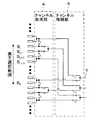
図3(A)および(B)に、アレイトランスジューサ3の一例を示す。このアレイトランスジューサ3は、多数のサブダイス素子数、例えば384個のサブダイス素子がそれぞれ100μmの同一ピッチPでアレイ状に配列され、約7.5MHzの周波数で使用されるものである。各チャンネルを2つのサブダイス素子を接続して形成する場合には、図3(A)に示すように、サブダイス素子S1とS2、S3とS4、S5とS6、・・・をそれぞれ接続し、各チャンネルを3つのサブダイス素子を接続して形成する場合には、図3(B)に示すように、サブダイス素子S1〜S3、S4〜S6、S7〜S9、・・・をそれぞれ接続する。 3A and 3B show an example of the
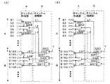
サブダイス素子の接続状態は、各チャンネルを構成するサブダイス素子数がそれぞれ同数となるように、チャンネル形成部4により切り換えられる。各チャンネルを構成するサブダイス素子数がそれぞれ2つまたは3つになるように接続状態を切り換える場合には、図4(A)および(B)に示すように、チャンネル形成部4は、サブダイス素子S1およびS2とサブダイス素子S3との接続状態を切り換えるスイッチSW1と、サブダイス素子S3とサブダイス素子S4との接続状態を切り換えるスイッチSW2およびSW3と、サブダイス素子S4とサブダイス素子S5およびS6との接続状態を切り換えるスイッチSW4と、以下同様にして各チャンネルを構成するサブダイス素子間の接続を切り換える複数のスイッチにより構成することができる。すなわち、チャンネル形成部4は、サブダイス素子S1とS2、S5とS6、S7とS8、S11とS12、S13とS14、・・・を常に接続し、サブダイス素子S3、S4、S9、S10、・・・の接続状態を切り換えるように構成することができる。 The connection state of the sub-die elements is switched by the
図4(A)に示すように、各チャンネルを2つのサブダイス素子により形成する場合には、チャンネル形成部4は、スイッチSW1、SW4・・・を開放すると共に、スイッチSW2、SW3、・・・を接続する。このようにして、それぞれ2つのサブダイス素子からなる192個のチャンネルとチャンネル接続部6から延びる192本の入出力線L1〜L192とをそれぞれ接続する。一方、図4(B)に示すように、各チャンネルを3つのサブダイス素子により形成する場合には、チャンネル形成部4は、スイッチSW1、SW4・・・を接続すると共に、スイッチSW2、SW3、・・・を開放する。このようにして、それぞれ3つのサブダイス素子からなる128個のチャンネルと192本の入出力線のうち128本の入出力線L1、L3、L4、L6・・・とをそれぞれ接続する。なお、192本の入出力線のうち各チャンネルと接続されない64本の入出力線L2、L5、L8・・・は装置本体2のTx/Rx回路に接続されていない。
チャンネル形成部4により形成された複数のチャンネルのうち所定数のチャンネルが、チャンネル接続部6により装置本体2から延びる複数の信号線7に順次選択的に接続される。すなわち、チャンネル接続部6は、チャンネル形成部4により形成された複数のチャンネルのうち2以上のチャンネルを同一の信号線7に排他的に割り付ける。例えば、図4(A)および(B)に示すように、複数の信号線7とサブダイス素子S1〜S192との接続状態を切り換えるスイッチSW5、SW7、・・・と、複数の信号線7とサブダイス素子S193〜S384との接続状態を切り換えるスイッチSW6、SW8、・・・とを有し、2:1の切り換えを行うチャンネル接続部6が利用できる。このような2:1のチャンネル接続部6は、チャンネル形成部4により形成された複数のチャンネルのうちこれを等分割した数で構成されるAグループのチャンネルを信号線7に接続し、超音波の送受信に伴って信号線7と接続されるチャンネルの位置を所定の素子数分だけ順次移動させていく。チャンネル接続部6は、信号線7と接続されるチャンネルの位置の移動をBグループのチャンネルが信号線7に接続されるまで繰り返す。すなわち、チャンネル形成部4により192個のチャンネルが形成されたときには、96個のチャンネルからなるAグループから96個のチャンネルからなるBグループまで順次選択的に信号線7に接続され、チャンネル形成部4により128個のチャンネルが形成されたときには、64個のチャンネルからなるAグループから64個のチャンネルからなるBグループまで順次選択的に信号線7に接続される。As shown in FIG. 4A, when each channel is formed by two sub-die elements, the
A predetermined number of channels among the plurality of channels formed by the
次に、超音波診断装置の動作について説明する。
まず、図1において、サブダイス素子の個数Kを384個とすると共に入出力線5の本数Mを192本とした超音波プローブ1をTx/Rx回路8の個数Nを96個とした装置本体2に96本の信号線7を有する接続ケーブルを介して接続する。なお、超音波プローブ1には、2:1の切り換えを行うチャンネル接続部6が内蔵されているものとする。
装置本体2に接続された超音波プローブ1は、図4(A)に示すように、チャンネル形成部4のスイッチSW1、SW4・・・が開放されると共にスイッチSW2、SW3、・・・が接続されることにより、それぞれ2つのサブダイス素子を接続した192個のチャンネルからなるアレイトランスジューサ3が形成される。また、超音波プローブ1のチャンネル接続部6のスイッチSW5、SW7、・・・が接続されると共にスイッチSW6、SW8・・・が開放され、チャンネル形成部4により形成された192個のチャンネルのうちAグループの96個のチャンネルと96本の信号線がそれぞれ接続される。Next, the operation of the ultrasonic diagnostic apparatus will be described.
First, in FIG. 1, the
As shown in FIG. 4A, the
このように、超音波プローブ1はチャンネル接続部6を内蔵するため、各チャンネルに接続された入出力線5の本数(192本)に比べ、超音波プローブ1と装置本体2を接続する接続ケーブルに内蔵された信号線7の本数(96本)を少なくすることができ、これに伴い超音波プローブ1の操作性等を向上させることができる。 As described above, since the
超音波プローブ1と装置本体2が接続されると、装置本体2に内蔵された96個のTx/Rx回路8から96本の信号線7(有効信号線)を介して超音波プローブ1のチャンネル接続部6に駆動信号が供給される。チャンネル接続部6は、スイッチSW5、SW7、・・・と接続された入出力線L1、L2、・・・L96を介して駆動信号をチャンネル形成部4に供給する。チャンネル形成部4に供給された駆動信号は、サブダイス素子S1とS2、S3とS4、・・・S191とS192をそれぞれ接続して構成されたAグループの96個の各チャンネルにそれぞれ供給される。これにより、Aグループの各チャンネルから図示しない被検体に向けて超音波がそれぞれ送信される。また、被検体により反射された超音波エコーはAグループの各チャンネルで受信され、その受信信号が同様の経路を経て装置本体2の各Tx/Rx回路8に入力される。
続いて、超音波プローブ1のチャンネル接続部6が96本の信号線7と接続される96個のチャンネルの位置が所定数だけ移動するようにスイッチを切り換え、超音波が送受信される。When the
Subsequently, the switch is switched so that a predetermined number of positions of the 96 channels connected to the 96
このようにして、超音波が送受信される度にチャンネル接続部6が信号線7と接続されるチャンネルの位置を所定数ずつ移動させ、最後に、図5(A)に示すように、チャンネル接続部6のスイッチSW5、SW7、・・・を開放すると共にスイッチSW6、SW8・・・を接続することにより、Bグループの96個のチャンネルと96本の信号線(有効信号線)がそれぞれ接続される。同様にして、装置本体2の各Tx/Rx回路8からチャンネル接続部6に駆動信号が供給され、その駆動信号がチャンネル接続部6のスイッチSW6、SW8、・・・と接続された入出力線L97、L98、・・・L192を介してBグループの各チャンネルにそれぞれ供給される。これにより、Bグループの各チャンネルから被検体に向けて超音波がそれぞれ送信されると共に被検体により反射された超音波エコーがBグループの各チャンネルから受信され、その受信信号が装置本体2の各Tx/Rx回路8に入力される。
このように、超音波ビームの走査は、有効信号線とAグループの各チャンネルを接続した状態より開始され、所定の素子数分だけ有効信号線と接続されるチャンネルを移動しながら超音波の送受信を繰り返し、有効信号線をBグループの各チャンネルと接続して超音波が送受信されたところで終了される。装置本体2は、各Tx/Rx回路8に入力された受信信号を処理することにより超音波画像を生成し、図示しないディスプレイ等に表示する。In this way, every time an ultrasonic wave is transmitted / received, the
As described above, the scanning of the ultrasonic beam starts from the state where the effective signal line and each channel of the A group are connected, and the transmission / reception of the ultrasonic wave is performed while moving the channel connected to the effective signal line by a predetermined number of elements. Is repeated, the effective signal line is connected to each channel of the B group, and the process is terminated when the ultrasonic wave is transmitted and received. The apparatus
一方、Tx/Rx回路8の個数Nを64個とした装置本体2に超音波プローブ1を接続する場合には、図4(B)に示すように、チャンネル形成部4のスイッチSW1、SW4・・・が接続されると共にスイッチSW2、SW3、・・・が開放されることにより、それぞれ3つのサブダイス素子を接続した128個のチャンネルからなるアレイトランスジューサ3が形成される。チャンネル形成部4により形成された128個のチャンネルはチャンネル接続部6のスイッチSW5、SW6、・・・により、図4(B)に示すように、64個のAグループの各チャンネルとTx/Rx回路8にそれぞれ接続された64本の信号線(有効信号線)とがそれぞれ接続される。続いて、チャンネル接続部6は、超音波が送受信される度にスイッチを切り換え、64本の有効信号線と接続される64個のチャンネルの位置を所定数ずつ移動させる。このようにして、図5(B)に示すように、64個のBグループの各チャンネルと64本の有効信号線とを接続して超音波が送受信されたところで超音波ビームの走査が終了される。なお、接続ケーブルに内蔵された96本の信号線のうち装置本体2のTx/Rx回路8と接続されていない32本の信号線(有効信号線以外の信号線)は、各チャンネルとの接続に関与しないチャンネル接続部6のスイッチSW7、SW8、・・・(入出力線L2、L5、・・・)とそれぞれ接続されている。 On the other hand, when the
本実施形態によれば、チャンネル形成部4が装置本体2に内蔵されたTx/Rx回路8の個数に応じて超音波プローブ1のチャンネル数を変更するため、Tx/Rx回路8の規模の異なる複数の装置本体2に超音波プローブ1をそれぞれ対応させることができる。 According to the present embodiment, since the
なお、チャンネル形成部4により変更される各チャンネルのサブダイス素子数は2つおよび3つに限られず、サブダイス素子間の接続状態を切り換えるスイッチSWの位置や個数を変更することにより様々なサブダイス素子数から構成されるチャンネルを形成することができる。
また、チャンネル接続部6は2:1の切り換えを行うものに限られず、超音波を送受信する時間間隔に応じたMUXを利用することができる。
また、チャンネル接続部6は、サブダイス素子S1〜S384を2等分してサブダイス素子S1〜S192がAグループ、サブダイス素子S193〜S384がBグループとなるように切り換えを行うものに限られない。例えば、チャンネル接続部6は、図6に示すように、任意の位置のサブダイス素子Sj〜Sk(k=j+191)を素子選択範囲として同一のタイミングで複数の信号線7にそれぞれ接続されるように切り換えを行うことができる。続いて、素子選択範囲と複数の信号線7との接続状態が開放されると、素子選択範囲を挟んで離れた位置に分割配置されたサブダイス素子が複数の信号線7にそれぞれ接続されるように切り換えが行われる。また、素子選択範囲は任意の数のサブダイス素子から構成することもでき、さらに素子選択範囲とそれ以外の範囲のサブダイス素子を互いに異なる数から構成することもできる。Note that the number of sub-die elements for each channel changed by the
The
Further, the
実施形態2
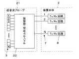
図7に実施形態2に係る超音波診断装置の構成を示す。この超音波診断装置では、図1に示した実施形態1の装置における超音波プローブ1に代えて超音波プローブ21が用いられている。超音波プローブ21は、実施形態1の超音波プローブ1において、チャンネル形成部4およびチャンネル接続部6の代わりにチャンネル形成・接続部22をアレイトランスジューサ3と信号線7との間に接続したものである。
チャンネル形成・接続部22は、アレイトランスジューサ3に配列された複数のサブダイス素子の接続状態を切り換えることにより各チャンネルを構成するサブダイス素子数を変更すると共にアレイトランスジューサ3を構成する複数のトランスジューサを装置本体2のTx/Rx回路8にそれぞれ接続された複数の信号線7に対応付けて接続する。
FIG. 7 shows the configuration of the ultrasonic diagnostic apparatus according to the second embodiment. In this ultrasonic diagnostic apparatus, an
The channel forming / connecting
例えば、2つまたは3つのサブダイス素子からなる複数のチャンネルを形成する場合には、図8(A)および(B)に示すようなチャンネル形成・接続部22により各チャンネルを構成するサブダイス素子の接続状態の切り換えを行うことができる。チャンネル形成・接続部22は、サブダイス素子S1およびS2とサブダイス素子S3との接続状態を切り換えるスイッチSW1と、サブダイス素子S3とサブダイス素子S4との接続状態を切り換えるスイッチSW2およびSW3と、サブダイス素子S4とサブダイス素子S5およびS6との接続状態を切り換えるスイッチSW4と、以下同様にして各チャンネルを構成するサブダイス素子間の接続を切り換える複数のスイッチを有する。チャンネル形成・接続部22は、各チャンネルを2つのサブダイス素子により形成する場合には、図8(A)に示すように、スイッチSW1、SW4・・・を開放すると共に、スイッチSW2、SW3、・・・を接続し、各チャンネルを3つのサブダイス素子により形成する場合には、図8(B)に示すように、スイッチSW1、SW4・・・を接続すると共に、スイッチSW2、SW3、・・・を開放する。
また、チャンネル形成・接続部22は、複数の信号線7とサブダイス素子S1〜S192との接続状態を切り換えるスイッチSW5、SW2、SW3、SW9・・・と、複数の信号線7とサブダイス素子S193〜S384との接続状態を切り換えるスイッチSW6、SW10・・・とを有する。これにより、複数のチャンネルのうちこれを等分割した数で構成されるAグループのチャンネルを信号線7に接続し、超音波の送受信に伴って信号線7と接続されるチャンネルの位置を所定の素子数分だけ順次移動させていく。チャンネル形成・接続部22は、信号線7と接続されるチャンネルの位置の移動をBグループのチャンネルが接続されるまで繰り返す。なお、スイッチSW2、SW3、・・・は、各チャンネルを構成するサブダイス素子間の接続を切り換えると共に複数の信号線7と各チャンネルとの接続状態の切り換えを行っている。すなわち、スイッチSW2、SW3、・・・は、複数のサブダイス素子間の接続を選択することによりそれぞれ複数のサブダイス素子からなる複数のチャンネルを形成すると共に複数のチャンネルのうち2以上のチャンネルを同一の信号線に排他的に割り付けるためのチャンネル形成・接続スイッチとして機能する。For example, in the case of forming a plurality of channels composed of two or three sub-die elements, connection of sub-die elements constituting each channel is performed by a channel forming / connecting
The channel forming / connecting
まず、図7において、サブダイス素子の個数Kを384個とした超音波プローブ21をTx/Rx回路8の個数Nを96個とした装置本体2に96本の信号線7を介して接続する。
装置本体2に接続された超音波プローブ1は、図8(A)に示すように、チャンネル形成・接続部22のスイッチSW1、SW4・・・が開放されると共にスイッチSW2、SW3、・・・が接続されることにより、それぞれ2つのサブダイス素子を接続した192個のチャンネルからなるアレイトランスジューサ3が形成される。また、チャンネル形成・接続部22のスイッチSW5、SW2、SW3、SW9・・・が接続されると共にスイッチSW6、SW10・・・が開放され、192個のチャンネルのうちAグループの96個のチャンネルと96本の信号線(有効信号線)がそれぞれ接続される。First, in FIG. 7, the
As shown in FIG. 8A, the
超音波プローブ1と装置本体2が接続されると、装置本体2に内蔵された96個のTx/Rx回路8から信号線7を介して超音波プローブ21のチャンネル形成・接続部22に駆動信号が供給される。チャンネル形成・接続部22は、Tx/Rx回路8から供給された駆動信号をスイッチSW5、SW2、・・・とそれぞれ接続されたAグループの96個の各チャンネルに供給する。
続いて、超音波が送受信される度に超音波プローブ21のチャンネル形成・接続部22が96本の信号線7と接続される96個のチャンネルの位置を所定数ずつ移動させていき、最後に96本の信号線7がBグループのチャンネルと接続される。超音波プローブ21は、チャンネル形成・接続部22のスイッチSW5、SW2、SW3・・・を開放すると共にスイッチSW6、SW10・・・を接続することにより、Bグループの96個のチャンネルと96本の信号線がそれぞれ接続される。同様にして、装置本体2の96個のTx/Rx回路8からチャンネル形成・接続部22に駆動信号が供給され、その駆動信号がスイッチSW6、SW10、・・・と接続されたBグループの各チャンネルにそれぞれ供給される。
このように、超音波ビームの走査は、有効信号線とAグループの各チャンネルを接続した状態より開始され、所定の素子数分だけ有効信号線と接続されるチャンネルを移動しながら超音波の送受信を繰り返し、有効信号線をBグループの各チャンネルと接続して超音波が送受信されたところで終了される。
なお、チャンネル形成・接続部22は、サブダイス素子S1〜S384を2等分してサブダイス素子S1〜S192がAグループ、サブダイス素子S193〜S384がBグループとなるように切り換えを行うものに限られず、任意の位置のサブダイス素子Sj〜Sk(k=j+191)を素子選択範囲として同一のタイミングで複数の信号線7にそれぞれ接続されるように切り換えを行うことができる。また、素子選択範囲は任意の数のサブダイス素子から構成することもでき、さらに素子選択範囲とそれ以外の範囲のサブダイス素子を互いに異なる数から構成することもできる。When the
Subsequently, every time ultrasonic waves are transmitted / received, the channel forming / connecting
As described above, the scanning of the ultrasonic beam starts from the state where the effective signal line and each channel of the A group are connected, and the transmission / reception of the ultrasonic wave is performed while moving the channel connected to the effective signal line by a predetermined number of elements. Is repeated, the effective signal line is connected to each channel of the B group, and the process is terminated when the ultrasonic wave is transmitted and received.
The channel forming / connecting
このように、チャンネル形成・接続部22が複数のTx/Rx回路8と接続された信号線7と各チャンネルとの接続をグループ毎に切り換えて超音波の送受信を行うため、各チャンネルの個数(192本)に比べ、超音波プローブ1と装置本体2を接続する接続ケーブルに内蔵された信号線7の本数(96本)を少なくすることができ、これに伴い超音波プローブ1の操作性等を向上させることができる。
また、チャンネル形成・接続部22のスイッチSW2、SW3、・・・が各チャンネルを構成するサブダイス素子間の接続を切り換えると共に複数の信号線7と各チャンネルとの接続状態の切り換えを行うため、実施形態1の超音波プローブ1に比べてスイッチの個数を減らして簡易な構成とすることができる。In this way, since the channel forming / connecting
Further, the switches SW2, SW3,... Of the channel forming / connecting
一方、Tx/Rx回路8の個数Nを64個とした装置本体2に超音波プローブ21を接続する場合には、図8(B)に示すように、チャンネル形成・接続部22のスイッチSW1、SW4・・・が接続されると共にスイッチSW2、SW3、・・・が開放されることにより、それぞれ3つのサブダイス素子を接続した128個のチャンネルからなるアレイトランスジューサ3が形成される。また、チャンネル形成・接続部22のスイッチSW5、SW9・・・により、128個のチャンネルがそれぞれ64個のAグループまたはBグループにグループ分けされる。AグループまたはBグループで同じTx/Rx回路8にそれぞれ接続される素子は、チャンネル形成・接続部22により排他的に選択された64本の信号線(有効信号線)と接続される。なお、接続ケーブルに内蔵された96本の信号線のうち装置本体2のTx/Rx回路8と接続されていない32本の信号線(有効信号線以外の信号線)は、各チャンネルとの接続に関与しないスイッチSW2、SW3、・・・とそれぞれ接続されている。 On the other hand, when the
本実施形態によれば、チャンネル形成・接続部22が装置本体2に内蔵されたTx/Rx回路8の個数に応じて超音波プローブ21のチャンネル数を変更するため、Tx/Rx回路8の規模の異なる複数の装置本体2に超音波プローブ21をそれぞれ対応させることができる。 According to the present embodiment, the channel forming / connecting
実施形態3
実施形態1および2に係る超音波診断装置は、1個の超音波プローブを複数の装置本体2に接続して用いることもできる。
例えば、実施形態1に示した384個のサブダイス素子と192本の入出力線5を有する超音波プローブ1において、チャンネル形成部4によりそれぞれ2つのサブダイス素子により構成される192個のチャンネルを形成した場合、この超音波プローブ1を64個のTx/Rx回路8を内蔵した装置本体2に接続すると、図9に示すように、192個のチャンネルのうち128個のチャンネルしか使用することができない。すなわち、192個のチャンネルと接続された192本の入出力線5のうち128本がチャンネル接続部6を介して装置本体の64個のTx/Rx回路8に接続され、残る64本はTx/Rx回路8に接続されない。
そこで、例えば図10に示すように、この超音波プローブ1をそれぞれ64個のTx/Rx回路8を備えた第1の装置本体31および第2の装置本体32に信号分配器33を介して接続することができる。チャンネル形成部4により2つのサブダイス素子がそれぞれ接続されて形成された192個のチャンネルは192本の入出力線5を介して2:1の切り換えを行うチャンネル接続部6に接続される。このチャンネル接続部6は、192本の入出力線5を96本の信号線7にそれぞれ接続すると共に信号分配器33を介して96本の信号線7を第1の装置本体31および第2の装置本体32にそれぞれ内蔵された48個のTx/Rx回路8と選択的に接続する。これにより、196個のチャンネルが第1の装置本体31および第2の装置本体32の有する96個のTx/Rx回路8にそれぞれ選択的に接続される。第1の装置本体31および第2の装置本体32は、互いに同一のタイミングで並列動作し、超音波プローブ1の192個のチャンネルから超音波の送受信を行う。
The ultrasonic diagnostic apparatuses according to the first and second embodiments can be used by connecting one ultrasonic probe to a plurality of apparatus
For example, in the
Therefore, for example, as shown in FIG. 10, the
本実施形態によれば、超音波プローブ1のチャンネル数に対して接続される装置本体2のTx/Rx回路の個数が少ない場合でも、複数の装置本体2を並列運転することにより同時に並行して処理し得る受信信号の数を向上させ、高画質の超音波画像を得ることできる。 According to the present embodiment, even when the number of Tx / Rx circuits of the apparatus
実施形態4
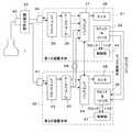
図11に、実施形態3で2台の装置本体を並列運転する際に用いた、第1の装置本体31および第2の装置本体32の内部構成を示す。第1の装置本体31は、ユニット側コネクタ34を介して信号分配器33に接続されるフロントエンド35を有し、このフロントエンド35にビームフォーマ36を介してバックエンド37が接続され、バックエンド37にモニタ38が接続されている。さらに、第1の装置本体31は、クロック・リトリガ回路39を有しており、このクロック・リトリガ回路39に制御部40が接続されている。
FIG. 11 shows an internal configuration of the first device
フロントエンド35は、nチャンネルのTx/Rx回路8を有し、信号分配器33を介して接続された超音波プローブ1の対応するチャンネルの振動子に駆動信号を供給すると共に被検体からの超音波エコーを受信することによりこれらチャンネルの振動子で生成された受信信号に対して直交検波処理等を施すことにより複素ベースバンド信号を生成し、複素ベースバンド信号をサンプリングすることにより、組織のエリアの情報を含むサンプルデータを生成する。フロントエンド35は、複素ベースバンド信号をサンプリングして得られるデータに高能率符号化のためのデータ圧縮処理を施すことによりサンプルデータを生成してもよい。 The
ビームフォーマ36は、制御部40により設定された受信方向に応じて、予め記憶されている複数の受信遅延パターンの中から1つの受信遅延パターンを選択し、選択された受信遅延パターンに基づいて、サンプルデータによって表される複数の複素ベースバンド信号にそれぞれの遅延を与えて加算することにより、受信フォーカス処理を行う。この受信フォーカス処理により、超音波エコーの焦点が絞り込まれたベースバンド信号(音線信号)が生成される。 The
バックエンド37は、ビームフォーマ36によって生成される音線信号に基づいて、被検体内の組織に関する断層画像情報であるBモード画像信号を生成する。バックエンド37は、STC(sensitivity time control)部と、DSC(digital scan converter:デジタル・スキャン・コンバータ)とを含んでいる。STC部は、音線信号に対して、超音波の反射位置の深度に応じて、距離による減衰の補正を施す。DSCは、STC部によって補正された音線信号を通常のテレビジョン信号の走査方式に従う画像信号に変換(ラスター変換)し、階調処理等の必要な画像処理を施すことにより、Bモード画像信号を生成する。 The
モニタ38は、バックエンド37によって生成される画像信号に基づいて超音波診断画像を表示する。
クロック・リトリガ回路39は、クロック信号を診断装置ユニット1内の各部に供給すると共に、このクロック信号によりリトリガされたトリガ信号を第1の装置本体31内の各部に供給するものである。
また、制御部40は、第1の装置本体31内の各部の動作を制御する。The
The
Further, the control unit 40 controls the operation of each unit in the first apparatus
一方、第2の装置本体32も、第1の装置本体31と同様の内部構成を有している。すなわち、第2の装置本体32は、ユニット側コネクタ41を介して信号分配器33に接続されるフロントエンド42を有し、このフロントエンド42にビームフォーマ43を介してバックエンド44が接続され、バックエンド44にモニタ45が接続されている。さらに、第2の装置本体32は、クロック・リトリガ回路46を有しており、このクロック・リトリガ回路46に制御部47が接続されている。
これら第2の装置本体32内の各部は、第1の装置本体31内の同一名称の各部と同様の機能を有している。On the other hand, the second device
Each part in the second apparatus
第1の装置本体31および第2の装置本体32が並列運転されるときには、例えば第1の装置本体31がマスター装置本体として、第2の装置本体32がスレーブ装置本体としてそれぞれ選択されて機能し、図11に示されるように、第2の装置本体32のビームフォーマ43がデータバス48を介して第1の装置本体31のバックエンド37に接続されると共に、第2の装置本体32のバックエンド44およびクロック・リトリガ回路46が動作制御ケーブルを介して第1の装置本体31のバックエンド37およびクロック・リトリガ回路39にそれぞれ接続される。 When the
信号分配器33に接続されているユニット側コネクタ34および41には、互いに異なる識別番号(ID番号)が予め設定されており、第1の装置本体31および第2の装置本体32は、ユニット側コネクタ34が接続されると、このユニット側コネクタ34の識別番号により、マスター装置本体として機能することを認識し、ユニット側コネクタ41が接続されると、このユニット側コネクタ41の識別番号により、スレーブ装置本体として機能することを認識するように構成されている。
また、超音波プローブ1に接続されているプローブコネクタ49にも、ユニット側コネクタ34および41とは異なる識別番号が予め設定されており、第1の装置本体31および第2の装置本体32は、プローブコネクタ49が直接接続されると、並列運転を行わず、それぞれ単独で通常の超音波診断動作を行うことを認識する。Different identification numbers (ID numbers) are set in advance in the
Also, the
次に、並列運転時の動作について説明する。
まず、信号分配器33により、超音波プローブ1のアレイトランスジューサ3の複数のチャンネルのうち偶数番目に配列されたチャンネルが第1の装置本体31に接続されると共に奇数番目に配列されたチャンネルが第2の装置本体32に接続されるものとする。
スレーブ装置本体として機能する第2の装置本体32は、第1の装置本体31のクロック・リトリガ回路39から供給された同期用クロック信号およびメイントリガ信号に従って動作する。Next, the operation at the time of parallel operation will be described.
First, the
The second device
例えば、「m」を自然数として、第1の装置本体31のフロントエンド35から超音波プローブ1の(2m+2)番目のチャンネルの振動子に駆動信号を供給すると共に第2の装置本体32のフロントエンド42から超音波プローブ1の(2m+3)番目のチャンネルの振動子に駆動信号を供給することにより、互いに隣接するこれら2つのチャンネルから超音波が送信されると、被検体からの超音波エコーを受信した超音波プローブ1の各チャンネルの振動子は、それぞれ受信信号を出力する。 For example, with “m” as a natural number, a drive signal is supplied from the
そして、振動子アレイの偶数番目に配列されたチャンネルの振動子から出力された受信信号が第1の装置本体31のフロントエンド35に入力されてサンプルデータが生成されると共に、振動子アレイの奇数番目に配列されたチャンネルの振動子から出力された受信信号が第2の装置本体32のフロントエンド42に入力されてサンプルデータが生成される。このとき、第2の装置本体32は、第1の装置本体31のクロック・リトリガ回路39から供給された同期用クロック信号およびメイントリガ信号に従って動作するため、第1の装置本体31のフロントエンド35と第2の装置本体32のフロントエンド42は、互いに同一タイミングでサンプルデータを生成する。 The reception signal output from the transducers of the even-numbered channels of the transducer array is input to the
第1の装置本体31では、フロントエンド35で生成されたサンプルデータに対してビームフォーマ36が受信フォーカス処理を行うことにより、音線信号が生成され、バックエンド37に供給される。一方、第2の装置本体32においても、フロントエンド42で生成されたサンプルデータに対してビームフォーマ43が受信フォーカス処理を行うことにより、音線信号が生成されるが、この音線信号は、データバス48を介して第1の装置本体31のバックエンド37に供給される。
なお、このとき、第1の装置本体31および第2の装置本体32は、超音波プローブ1のそれぞれのチャンネルに対して、各チャンネルを構成する複数のサブダイス素子で位相整合を行い、複数方向の超音波ビームを合成し、合成結果に基づいて音線信号を生成するように構成することもできる。In the first apparatus
At this time, the first apparatus
このようにして双方の装置本体31および32のビームフォーマ36および43で生成された音線信号が供給されると、第1の装置本体31のバックエンド37は、これらの音線信号を合成し、合成された音線信号に基づいて、被検体内の組織に関する断層画像情報であるBモード画像信号を生成する。この画像信号が第1の装置本体31のモニタ38に送られ、超音波診断画像がモニタ38に表示される。 When the sound ray signals generated by the
本実施形態によれば、第1の装置本体31および第2の装置本体32はそれぞれnチャンネルの超音波送受信回路を有しているので、それぞれ単独で通常の超音波診断動作を行う際には、同時に並行して処理し得る受信信号の数は「n」であるが、双方の装置本体31および32を同期運転することにより、同時に並行して処理し得る受信信号の数は、単独の場合の2倍の「2n」となる。このため、高画質の超音波画像を得ることが可能となる。 According to the present embodiment, since the first apparatus
1,21 超音波プローブ、2 装置本体、3 アレイトランスジューサ、4 チャンネル形成部、5 入出力線、6 チャンネル接続部、7 信号線、8 Tx/Rx回路、9 圧電振動子、10 電極、11 制動材、12 音響整合層、13 音響レンズ、22 チャンネル形成・接続部、31 第1の装置本体、32 第2の装置本体、33 信号分配器、34,41 ユニット側コネクタ、35,42 フロントエンド、36,43 ビームフォーマ、37,44 バックエンド、38,45 モニタ、39,46 クロック・リトリガ回路、40,47 制御部、48 データバス、49 プローブコネクタ。 1,21 ultrasonic probe, 2 device main body, 3 array transducer, 4 channel forming unit, 5 input / output line, 6 channel connecting unit, 7 signal line, 8 Tx / Rx circuit, 9 piezoelectric vibrator, 10 electrode, 11 braking Material, 12 acoustic matching layer, 13 acoustic lens, 22 channel forming / connecting part, 31 first device main body, 32 second device main body, 33 signal distributor, 34, 41 unit side connector, 35, 42 front end, 36, 43 Beamformer, 37, 44 Back end, 38, 45 Monitor, 39, 46 Clock retrigger circuit, 40, 47 Control unit, 48 Data bus, 49 Probe connector.
Claims (5)
Translated fromJapaneseアレイトランスジューサを構成する各トランスジューサが厚み振動以外の不要振動を抑えて超音波を送受信するように複数のサブダイス素子より構成され、
より少ない送受信回路を有する装置本体に対応してチャンネル数を減少させる場合には各チャンネルを構成するサブダイス素子の数が増加するように複数のサブダイス素子の接続状態を切り換えると共にアレイトランスジューサを構成する複数のトランスジューサを複数の信号線のいずれかに対応付けて選択的に接続することにより複数の信号線のうち各チャンネルに接続されて駆動信号および受信信号を伝送する有効信号線を選択するチャンネル形成・接続部を備えることを特徴とする超音波プローブ。An ultrasonic beam is transmitted from the array transducer toward the subject based on the drive signal transmitted from the device main body via a plurality of signal lines to the device main body that controls transmission / reception of ultrasonic waves. An ultrasonic probe for transmitting reception signals obtained by receiving acoustic echoes with an array transducer viaa plurality of signal linesconnected to a plurality of transmission / reception circuits of the apparatus body,
Each transducer constituting the array transducer is composed of a plurality of sub-die elements so as to transmit / receive ultrasonic waves while suppressing unnecessary vibration other than thickness vibration,
When the number of channels is reduced corresponding to a device body having a smaller number of transmission / reception circuits, the connection stateof a plurality of sub-die elements is switchedand a plurality of elements constituting an array transducer are configuredso that the number of sub-die elements constituting each channel is increased. A channel is formed to select an effective signal line that is connected to each channel and transmits a drive signal and a received signal among a plurality of signal lines by selectively connecting the transducer to one of the plurality of signal lines. An ultrasonic probe comprising a connecting portion.
複数のサブダイス素子間の接続を選択することによりそれぞれ複数のサブダイス素子からなる複数のチャンネルを形成すると共に複数のチャンネルのうち2以上のチャンネルを同一の信号線に排他的に割り付けるためのチャンネル形成・接続スイッチを有することを特徴とする請求項1に記載の超音波プローブ。The channel forming / connecting portion is:
Channel formation for forming a plurality of channels each consisting of a plurality of sub-die elements by selecting connections between a plurality of sub-die elements and exclusively allocating two or more of the plurality of channels to the same signal line The ultrasonic probe according to claim 1, further comprising a connection switch.
複数のサブダイス素子間の接続を選択することによりそれぞれ複数のサブダイス素子からなる複数のチャンネルを形成するための複数のスイッチを有するチャンネル形成部と、
前記チャンネル形成部で形成された複数のチャンネルのうち2以上のチャンネルを同一の信号線に排他的に割り付けるための複数のスイッチを有するチャンネル接続部と
を含み、
複数の信号線のうち前記チャンネル接続部により各チャンネルと接続された信号線が前記有効信号線となることを特徴とする請求項1に記載の超音波プローブ。The channel forming / connecting portion is:
A channel forming section having a plurality of switches for forming a plurality of channels each consisting of a plurality of sub-die elements by selecting a connection between the plurality of sub-die elements;
A channel connecting unit having a plurality of switches for exclusively allocating two or more channels among the plurality of channels formed by the channel forming unit to the same signal line,
2. The ultrasonic probe according to claim 1, wherein a signal line connected to each channel by the channel connection unit among the plurality of signal lines becomes the effective signal line.
それぞれ対応する前記有効信号線に接続される複数の送受信回路を有する少なくとも1台の装置本体と
を有し、
前記チャンネル形成・接続部による複数のサブダイス素子の接続状態の切り換えは、前記少なくとも1台の装置本体の有する送受信回路の総数に応じて行われることを特徴とする超音波診断装置。The ultrasonic probe according to any one of claims 1 to 4,
And at least one device body having a plurality of transmission / reception circuits connected to the corresponding effective signal lines,
Switching of connection states of a plurality of sub-die elements by the channel forming / connecting unit is performed according to the total number of transmission / reception circuits included in the at least one apparatus main body.
Priority Applications (3)
| Application Number | Priority Date | Filing Date | Title |
|---|---|---|---|
| JP2011012773AJP5244201B2 (en) | 2011-01-25 | 2011-01-25 | Ultrasonic probe and ultrasonic diagnostic apparatus |
| US13/337,925US20120190986A1 (en) | 2011-01-25 | 2011-12-27 | Ultrasound probe and ultrasound diagnostic apparatus |
| CN2011104499072ACN102599931A (en) | 2011-01-25 | 2011-12-29 | Ultrasound probe and ultrasound diagnostic apparatus |
Applications Claiming Priority (1)
| Application Number | Priority Date | Filing Date | Title |
|---|---|---|---|
| JP2011012773AJP5244201B2 (en) | 2011-01-25 | 2011-01-25 | Ultrasonic probe and ultrasonic diagnostic apparatus |
Publications (2)
| Publication Number | Publication Date |
|---|---|
| JP2012152317A JP2012152317A (en) | 2012-08-16 |
| JP5244201B2true JP5244201B2 (en) | 2013-07-24 |
Family
ID=46517979
Family Applications (1)
| Application Number | Title | Priority Date | Filing Date |
|---|---|---|---|
| JP2011012773AExpired - Fee RelatedJP5244201B2 (en) | 2011-01-25 | 2011-01-25 | Ultrasonic probe and ultrasonic diagnostic apparatus |
Country Status (3)
| Country | Link |
|---|---|
| US (1) | US20120190986A1 (en) |
| JP (1) | JP5244201B2 (en) |
| CN (1) | CN102599931A (en) |
Cited By (1)
| Publication number | Priority date | Publication date | Assignee | Title |
|---|---|---|---|---|
| KR102663136B1 (en) | 2019-02-22 | 2024-05-03 | 우시 히스키 메디칼 테크놀로지스 컴퍼니., 리미티드. | ultrasonic imaging device |
Families Citing this family (10)
| Publication number | Priority date | Publication date | Assignee | Title |
|---|---|---|---|---|
| JP6606826B2 (en)* | 2015-01-09 | 2019-11-20 | コニカミノルタ株式会社 | Ultrasonic diagnostic equipment |
| CN104780488B (en)* | 2015-03-25 | 2019-03-26 | 重庆清文科技有限公司 | Adjustable ultrasonic wave directional loudspeaker and method |
| CN105935300A (en)* | 2016-04-29 | 2016-09-14 | 苏州斯科特医学影像科技有限公司 | Multichannel wireless palmtop color Doppler ultrasound device |
| WO2019144361A1 (en)* | 2018-01-25 | 2019-08-01 | 深圳市贝瑞森传感科技有限公司 | Ultrasonic transceiver probe, ultrasonic transduction array device and fetal doppler |
| JP7105172B2 (en)* | 2018-11-01 | 2022-07-22 | 富士フイルムヘルスケア株式会社 | Ultrasonic probe and ultrasonic diagnostic equipment |
| CN110720948B (en)* | 2019-11-12 | 2021-02-02 | 无锡海斯凯尔医学技术有限公司 | Biosign detection method based on ultrasonic detection system |
| CN111407312A (en)* | 2020-04-01 | 2020-07-14 | 艾因蒂克检测科技(上海)股份有限公司 | Area array probe with switching circuit |
| FR3109826B1 (en) | 2020-04-30 | 2022-08-19 | Moduleus | Ultrasound imaging device |
| CN113945936B (en)* | 2021-09-27 | 2025-07-29 | 珠海上富电技股份有限公司 | Ultrasonic sensor control method and system and vehicle |
| US12408895B2 (en) | 2022-11-10 | 2025-09-09 | Fujifilm Corporation | Ultrasound probe and ultrasound diagnostic apparatus |
Family Cites Families (9)
| Publication number | Priority date | Publication date | Assignee | Title |
|---|---|---|---|---|
| JPH0664022B2 (en)* | 1985-10-09 | 1994-08-22 | 株式会社日立メデイコ | Ultrasonic imaging device |
| JPS639428A (en)* | 1986-06-30 | 1988-01-16 | 横河メディカルシステム株式会社 | Ultrasonic probe |
| US5902241A (en)* | 1997-11-24 | 1999-05-11 | General Electric Company | Large-aperture imaging using transducer array with adaptive element pitch control |
| JP3934844B2 (en)* | 2000-02-28 | 2007-06-20 | 株式会社日立メディコ | Ultrasonic diagnostic equipment |
| US7443765B2 (en)* | 2003-03-06 | 2008-10-28 | General Electric Company | Reconfigurable linear sensor arrays for reduced channel count |
| EP1491914B1 (en)* | 2003-06-25 | 2006-10-18 | Aloka Co. Ltd. | Ultrasound diagnosis apparatus comprising a 2D transducer with variable subarray shape pattern |
| US20090306510A1 (en)* | 2005-06-17 | 2009-12-10 | Kunio Hashiba | Ultrasound Imaging Apparatus |
| JP2007244415A (en)* | 2006-03-13 | 2007-09-27 | Fujifilm Corp | Ultrasonic probe and ultrasonic diagnostic apparatus |
| JP2011000426A (en)* | 2009-05-19 | 2011-01-06 | Toshiba Corp | Ultrasonic diagnostic apparatus and ultrasonic probe |
- 2011
- 2011-01-25JPJP2011012773Apatent/JP5244201B2/ennot_activeExpired - Fee Related
- 2011-12-27USUS13/337,925patent/US20120190986A1/ennot_activeAbandoned
- 2011-12-29CNCN2011104499072Apatent/CN102599931A/ennot_activeWithdrawn
Cited By (1)
| Publication number | Priority date | Publication date | Assignee | Title |
|---|---|---|---|---|
| KR102663136B1 (en) | 2019-02-22 | 2024-05-03 | 우시 히스키 메디칼 테크놀로지스 컴퍼니., 리미티드. | ultrasonic imaging device |
Also Published As
| Publication number | Publication date |
|---|---|
| JP2012152317A (en) | 2012-08-16 |
| CN102599931A (en) | 2012-07-25 |
| US20120190986A1 (en) | 2012-07-26 |
Similar Documents
| Publication | Publication Date | Title |
|---|---|---|
| JP5244201B2 (en) | Ultrasonic probe and ultrasonic diagnostic apparatus | |
| US20100022883A1 (en) | Ultrasonic diagnostic apparatus | |
| JP3977827B2 (en) | Ultrasonic diagnostic equipment | |
| CN1242978A (en) | Supersonic array transducer receiver for handheld supersonic diagnosis instrument | |
| KR102025258B1 (en) | Image synthesis method and apparatus using plane wave in transducer having sub-array | |
| CN100405080C (en) | Diagnostic ultrasound imaging system with composite scanhead wiring | |
| US20070038082A1 (en) | Medical diagnostic ultrasound transducer system for harmonics | |
| CN103635829B (en) | 2D Ultrasound Diagnostic Imaging System with Two Beamformer Stages | |
| CN101889873A (en) | Ultrasonic diagnostic device and ultrasonic probe | |
| CN103402438B (en) | Diagnostic ultrasound equipment | |
| EP2832295A1 (en) | Ultrasonic probe and ultrasonic diagnostic device comprising same | |
| US10912538B2 (en) | Ultrasound diagnostic apparatus and method of producing ultrasound image | |
| JP4379576B2 (en) | Ultrasonic diagnostic equipment | |
| CN112971845B (en) | Ultrasonic diagnostic equipment and control method thereof | |
| US8876718B2 (en) | Ultrasound diagnostic apparatus and ultrasound image generating method | |
| JP2006102391A (en) | Ultrasonic diagnostic equipment | |
| US20090088642A1 (en) | Ultrasonic imaging apparatus and ultrasonic imaging method | |
| JP3413229B2 (en) | Ultrasound imaging device | |
| JP2007029268A (en) | Ultrasonic diagnostic equipment | |
| KR20030015576A (en) | Ultrasonic diagnostic imaging system | |
| JP2010115356A (en) | Ultrasonic probe and ultrasonic diagnostic apparatus | |
| JP5829229B2 (en) | Ultrasonic diagnostic apparatus and ultrasonic image generation method | |
| JP2005168903A (en) | Ultrasonic diagnostic equipment | |
| JPH06339479A (en) | Ultrasonic diagnostic device | |
| JP5299128B2 (en) | Ultrasonic probe, ultrasonic diagnostic equipment |
Legal Events
| Date | Code | Title | Description |
|---|---|---|---|
| A621 | Written request for application examination | Free format text:JAPANESE INTERMEDIATE CODE: A621 Effective date:20120618 | |
| A977 | Report on retrieval | Free format text:JAPANESE INTERMEDIATE CODE: A971007 Effective date:20121221 | |
| A131 | Notification of reasons for refusal | Free format text:JAPANESE INTERMEDIATE CODE: A131 Effective date:20130108 | |
| A521 | Written amendment | Free format text:JAPANESE INTERMEDIATE CODE: A523 Effective date:20130307 | |
| TRDD | Decision of grant or rejection written | ||
| A01 | Written decision to grant a patent or to grant a registration (utility model) | Free format text:JAPANESE INTERMEDIATE CODE: A01 Effective date:20130326 | |
| A61 | First payment of annual fees (during grant procedure) | Free format text:JAPANESE INTERMEDIATE CODE: A61 Effective date:20130405 | |
| FPAY | Renewal fee payment (event date is renewal date of database) | Free format text:PAYMENT UNTIL: 20160412 Year of fee payment:3 | |
| R150 | Certificate of patent or registration of utility model | Free format text:JAPANESE INTERMEDIATE CODE: R150 | |
| LAPS | Cancellation because of no payment of annual fees |