JP5243868B2 - Apparatus and method for recognizing information held by IC tag - Google Patents
Apparatus and method for recognizing information held by IC tagDownload PDFInfo
- Publication number
- JP5243868B2 JP5243868B2JP2008178940AJP2008178940AJP5243868B2JP 5243868 B2JP5243868 B2JP 5243868B2JP 2008178940 AJP2008178940 AJP 2008178940AJP 2008178940 AJP2008178940 AJP 2008178940AJP 5243868 B2JP5243868 B2JP 5243868B2
- Authority
- JP
- Japan
- Prior art keywords
- antenna
- tag
- read
- information
- unit
- Prior art date
- Legal status (The legal status is an assumption and is not a legal conclusion. Google has not performed a legal analysis and makes no representation as to the accuracy of the status listed.)
- Active
Links
Images


Classifications
- H—ELECTRICITY
- H04—ELECTRIC COMMUNICATION TECHNIQUE
- H04Q—SELECTING
- H04Q9/00—Arrangements in telecontrol or telemetry systems for selectively calling a substation from a main station, in which substation desired apparatus is selected for applying a control signal thereto or for obtaining measured values therefrom
- G—PHYSICS
- G06—COMPUTING OR CALCULATING; COUNTING
- G06K—GRAPHICAL DATA READING; PRESENTATION OF DATA; RECORD CARRIERS; HANDLING RECORD CARRIERS
- G06K17/00—Methods or arrangements for effecting co-operative working between equipments covered by two or more of main groups G06K1/00 - G06K15/00, e.g. automatic card files incorporating conveying and reading operations
- G06K17/0022—Methods or arrangements for effecting co-operative working between equipments covered by two or more of main groups G06K1/00 - G06K15/00, e.g. automatic card files incorporating conveying and reading operations arrangements or provisions for transferring data to distant stations, e.g. from a sensing device
- G06K17/0029—Methods or arrangements for effecting co-operative working between equipments covered by two or more of main groups G06K1/00 - G06K15/00, e.g. automatic card files incorporating conveying and reading operations arrangements or provisions for transferring data to distant stations, e.g. from a sensing device the arrangement being specially adapted for wireless interrogation of grouped or bundled articles tagged with wireless record carriers
- G—PHYSICS
- G06—COMPUTING OR CALCULATING; COUNTING
- G06K—GRAPHICAL DATA READING; PRESENTATION OF DATA; RECORD CARRIERS; HANDLING RECORD CARRIERS
- G06K7/00—Methods or arrangements for sensing record carriers, e.g. for reading patterns
- G06K7/10—Methods or arrangements for sensing record carriers, e.g. for reading patterns by electromagnetic radiation, e.g. optical sensing; by corpuscular radiation
- G06K7/10009—Methods or arrangements for sensing record carriers, e.g. for reading patterns by electromagnetic radiation, e.g. optical sensing; by corpuscular radiation sensing by radiation using wavelengths larger than 0.1 mm, e.g. radio-waves or microwaves
- G06K7/10316—Methods or arrangements for sensing record carriers, e.g. for reading patterns by electromagnetic radiation, e.g. optical sensing; by corpuscular radiation sensing by radiation using wavelengths larger than 0.1 mm, e.g. radio-waves or microwaves using at least one antenna particularly designed for interrogating the wireless record carriers
- G06K7/10356—Methods or arrangements for sensing record carriers, e.g. for reading patterns by electromagnetic radiation, e.g. optical sensing; by corpuscular radiation sensing by radiation using wavelengths larger than 0.1 mm, e.g. radio-waves or microwaves using at least one antenna particularly designed for interrogating the wireless record carriers using a plurality of antennas, e.g. configurations including means to resolve interference between the plurality of antennas
- H—ELECTRICITY
- H04—ELECTRIC COMMUNICATION TECHNIQUE
- H04Q—SELECTING
- H04Q2209/00—Arrangements in telecontrol or telemetry systems
- H04Q2209/40—Arrangements in telecontrol or telemetry systems using a wireless architecture
- H04Q2209/47—Arrangements in telecontrol or telemetry systems using a wireless architecture using RFID associated with sensors
Landscapes
- Engineering & Computer Science (AREA)
- Computer Networks & Wireless Communication (AREA)
- Physics & Mathematics (AREA)
- General Physics & Mathematics (AREA)
- Theoretical Computer Science (AREA)
- Health & Medical Sciences (AREA)
- Toxicology (AREA)
- General Engineering & Computer Science (AREA)
- Electromagnetism (AREA)
- General Health & Medical Sciences (AREA)
- Artificial Intelligence (AREA)
- Computer Vision & Pattern Recognition (AREA)
Description
Translated fromJapanese本発明は、ICタグが保持する情報を認識する装置及び方法に関するものである。 The present invention relates to an apparatus and a method for recognizing information held by an IC tag.
従来から商品識別・管理に利用されているバーコードシステムに代わるものとして、電波ないし電磁波を媒体とするRFID(Radio Frequency IDentification)システムが提案されている。このRFIDシステムは、バーコードに比べデータの書き換えができる点でも優れている。RFIDシステムの適用例としては、小売業界での商品流通管理への適用、店頭における盗難防止装置への適用、工場内での工程管理への適用、鉄道機関の自動改札精算装置への適用等が挙げられる。 An RFID (Radio Frequency IDentification) system using radio waves or electromagnetic waves as a medium has been proposed as an alternative to a barcode system conventionally used for product identification and management. This RFID system is also superior in that data can be rewritten compared to a barcode. Examples of application of RFID systems include merchandise distribution management in the retail industry, application to anti-theft devices at stores, application to process management in factories, and application to automatic ticket checkout equipment at railway agencies. Can be mentioned.
従来では、個人情報等が記憶された無線カードを使用し、交信端末装置との間で個人情報等を含む各種の無線処理情報の送受信を行う無線カード処理システムが提案されている(例えば、特許文献1参照)。この特許文献1には、主アンテナ、補助アンテナ、交信手段、応答信号判定手段及び制御手段を具備する交信端末装置が開示されている。交信端末装置の主アンテナ及び補助アンテナは、送受信感度を高低に異ならせて配置され、無線応答信号及び無線処理情報を送信する無線カードとの間で無線交信を行う。交信手段は、主アンテナ及び補助アンテナを介して各々無線カードに対する送信要求信号を送信するとともに無線カードからの無線応答信号の受信を行う。応答信号判定手段は、交信手段にて受信する無線応答信号が主アンテナ又は補助アンテナのいずれにより受信されたかを判定する。制御手段は、応答信号判定手段による主アンテナからの無線応答信号の受信であるとの判定結果により無線カードの交信意志を確認して、無線カードとの間で無線処理情報の交信を実行する。 Conventionally, there has been proposed a wireless card processing system that uses a wireless card in which personal information and the like are stored, and transmits and receives various types of wireless processing information including personal information and the like with a communication terminal device (for example, patents). Reference 1). This patent document 1 discloses a communication terminal device including a main antenna, an auxiliary antenna, communication means, response signal determination means, and control means. The main antenna and the auxiliary antenna of the communication terminal apparatus are arranged with different transmission and reception sensitivities, and perform wireless communication with a wireless card that transmits a wireless response signal and wireless processing information. The communication means transmits a transmission request signal for each wireless card via the main antenna and the auxiliary antenna and receives a wireless response signal from the wireless card. The response signal determination unit determines whether the radio response signal received by the communication unit is received by the main antenna or the auxiliary antenna. The control means confirms the communication intention of the wireless card based on the determination result that the response signal determination means receives the wireless response signal from the main antenna, and executes communication of wireless processing information with the wireless card.
ここで、RFIDシステムにてICタグのIDを読み取るリーダとして、同時に複数のICタグを読み取れるタイプがある。このようなタイプのリーダを、例えば荷物にICタグを付けて複数の荷物を管理するシステムに適用する場合に不都合な事態が生じることが考えられる。すなわち、リーダは、作業員がアンテナに意図的にかざしたICタグだけではなく、その周囲にあるICタグも作業員が意図せずに読み取ってしまうことがある。意図的にアンテナにかざしたICタグ以外のICタグを読み込まないようにするために、例えばアンテナの出力や位置、向き等を調整するという方策が考えられる。しかしながら、アンテナ近くにある荷物のICタグを読み取る可能性を排除できない。 Here, as a reader that reads an ID of an IC tag in an RFID system, there is a type that can simultaneously read a plurality of IC tags. It is conceivable that an inconvenient situation occurs when such a type of reader is applied to a system for managing a plurality of packages by attaching an IC tag to the package, for example. That is, the reader may unintentionally read not only the IC tag intentionally held by the worker over the antenna but also the IC tag around it. In order not to read an IC tag other than the IC tag intentionally held over the antenna, for example, a method of adjusting the output, position, orientation, etc. of the antenna can be considered. However, the possibility of reading an IC tag of a package near the antenna cannot be excluded.
本発明は、ICタグをアンテナに意図的にかざした場合とそうでない場合とを区別することが可能な、ICタグが保持する情報を認識する装置及び方法を提供することを目的とする。 An object of the present invention is to provide an apparatus and a method for recognizing information held by an IC tag, which can distinguish between a case where the IC tag is intentionally held over an antenna and a case where the IC tag is not held.
かかる目的のもと、本発明は、ICタグが保持する情報を認識する装置であって、ICタグからの電波を受信する第1のアンテナ及び第2のアンテナを備え、第1のアンテナによる読み取り可能な範囲である領域と、第2のアンテナによる読み取り可能な範囲である領域と、第1のアンテナ及び第2のアンテナによる読み取り可能な範囲である領域と、のうち少なくともいずれか2つの領域を組み合わせてなる複数の領域を形成するように構成されるアンテナ部と、アンテナ部を介してICタグの情報を読み取る読み取り部と、複数の領域にて最初にICタグの情報が読み取られてからの経過時間を計時する計時部と、複数の領域での第1のアンテナ及び第2のアンテナを介する情報の読み取りの有無および計時部による経過時間に基づいて、読み取り部に情報を読み取らせるための行為により読み取り部が読み取ったものか否かを判定し、かつ、計時部による経過時間が予め定められる値を超える場合に行為により読み取り部が読み取ったものではないと判定する判定部と、を含む、装置を提供する。For this purpose, the present invention is an apparatus for recognizing information held by an IC tag, comprising a first antenna and a second antenna for receiving radio waves from the IC tag, and reading by the first antenna. At least two of a region that is a possible range, a region that is a readable range by the second antenna, and a region that is a readable range by the first antenna and the second antenna. An antenna unit configured to form a plurality of combined regions, a reading unit that reads information of an IC tag via the antenna unit, and the IC tag information after being readfirst in the plurality of regions a timekeeping unit for measuring elapsed time based on theelapsed time of the first antenna andthe presenceand timing of the reading of information via the second antenna in a plurality of regionsDetermines whether or not the reading unit has read the act for to read the information in the readingunit, and does not read section has read the act when it exceeds the value over time by the timer unit is determined in advance including a determination unit todetermine that to provide a device.
ここで、判定部は、情報の読み取りの有無に基づいて、ICタグを有する物品が読み取り部の前を通過することにより読み取り部が読み取ったものか否かを判定する、ものであってもよい。また、判定部は、計時部による経過時間の計時開始後に第1のアンテナによる情報の読み取りがなく、かつ、第2のアンテナによる情報の読み取りがないことを契機に判定を行う、ものであってもよい。
また、アンテナ部の第1のアンテナおよび第2のアンテナは互いに異なる指向性を持つ、ものであってもよい。
更に、アンテナ部は、第1のアンテナの最大ゲインの方向で第2のアンテナのゲインが低くなるように構成され、第1のアンテナによる領域を第1のアンテナ及び第2のアンテナによる領域で挟むようにして複数の領域を形成する、ものであってもよい。Here, the determination unit may determine whether the reading unit has read the article having the IC tag by passing in front of the reading unit based on whether or not the information is read. . The determination unit does not read the information by the first antennaafter the start of counting of the elapsed time by the time measuring unit, andmakes a determinationin response to the absence reading of information by the second antenna, there is Also good.
In addition,the first antenna and the second antenna of the antenna unit may have different directivities .
Furthermore,the antenna unit,the gain of the second antenna in the direction of maximum gain of the first antenna is configured to be lower,the areathat by the first antenna to the first antenna and the second antennaA plurality of regions may be formedso as to besandwiched between regions.
更に、本発明は、ICタグが保持する情報を認識する方法であって、第1の領域に位置するICタグから情報が、第1のアンテナと第2のアンテナのいずれか一方又は両方のうち予め定められたアンテナで受信される受信態様で読み取られたか否かを判断するステップと、第1の領域の外である第2の領域に位置するICタグから情報が、第1の領域での受信態様とは異なる予め定められた別の受信態様で読み取られたか否かを判断するステップと、受信態様での読み取りと別の受信態様での読み取りのうち最初にICタグの情報が読み取られてからの経過時間を計時するステップと、第1の領域の外であると共に第2の領域の外でもある第3の領域に位置するICタグから情報が、第1のアンテナ及び第2のアンテナで読み取り不可であるか否かを判断するステップと、第1の領域にて受信態様で読み取りがなされたこと、第2の領域にて別の受信態様で読み取りがなされたこと及び第3の領域にて読み取り不可であること並びに計時される経過時間を条件に、ICタグの情報を読み取らせるための行為により情報を読み取ったものか否かを判定し、かつ、経過時間が予め定められる値を超える場合に行為により読み取ったものではないと判定するステップと、を含む、方法も提供する。Furthermore, the present invention is a method for recognizing information held by an IC tag, wherein information from an IC tag located in a first area is one of or both of a first antenna and a second antenna. A step of determining whether or not the signal has been read in a reception mode received by a predetermined antenna, and information from an IC tag located in a second area outside the first area The step of determining whether or not the data has been read in another predetermined reception mode different from the reception mode,and the information in the IC tag is read first in reading in the reception mode and reading in another reception mode. Information from an IC tag located in a third area that is outside the first area and outside the second area ismeasured by the first antenna and the second antenna. Unreadable A step of determining whether or not reading has been performed in the reception mode in the first area, reading has been performed in another reception mode in the second area, and reading is not possible in the third area. Ifthe elapsed time exceeds a predetermined value, it is determined whether or not the information has been read by an action for reading the information of the IC tag on the condition that theelapsed time iscounted.here it may include the steps of:determining that no method is also provided.
ここで、情報が受信態様で読み取られたか否かを判断するステップは、情報が別の受信態様で読み取られたか否かを判断するステップの前に行われると共にステップの次に行われる、ものであってもよい。Here, information determining whether read by the receiving aspect, information is performed in the next step with performed prior to the step of determining whether read by another receiver embodiment, in ones There may be.
本発明によれば、ICタグをアンテナに意図的にかざした場合とそうでない場合とを区別することが可能になる。 According to the present invention, it is possible to distinguish between the case where the IC tag is intentionally held over the antenna and the case where it is not.
以下、添付図面を参照して、本発明の実施の形態について詳細に説明する。
図1は、本実施の形態を適用した手荷物管理システムSを説明する斜視図である。
同図に示す手荷物管理システムSは、出発空港で航空機利用客(乗客)から預かった手荷物10を到着空港別のコンテナ12に積み込む際に使用されるものである。この手荷物管理システムSは、コンテナ12に積み込む手荷物10にIC(Integrated Circuit)タグ11を予め取り付けておくことで、RFIDシステムを利用してコンテナ12に積み込む手荷物10を認識している。この手荷物管理システムSを採用することで、手荷物10の追跡を行うことができる。なお、このRFIDシステムでは、複数のICタグ11を同時に読み取れる機能(アンチコリジョン(anti-collision)機能)を備える後述のリーダ(reader)22を用いている。
コンテナ12に積み込まれる手荷物10の各々には、ICタグ11が紐等で取り付けられている。このICタグ11は、外部と無線通信可能であり、個別データを保持可能に構成されている。すなわち、ICタグ11は、個別データを保持するための図示しないICチップと、個別データを送受信するための図示しないアンテナと、を備えている。Embodiments of the present invention will be described below in detail with reference to the accompanying drawings.
FIG. 1 is a perspective view illustrating a baggage management system S to which the present embodiment is applied.
The baggage management system S shown in the figure is used when
An
本実施の形態で用いられるICタグ11は、電池を内蔵せずにアンテナ21からの電波をエネルギー源として動作するパッシブタグ(受動タグ)である。ICタグ11は、アンテナ21からのエネルギーを受けてそれを受電してそのエネルギーを使って自分のICチップを作動してアンテナ21に電波を返す。より具体的に説明すると、本実施の形態のICタグ11は、整流回路を備えている。そして、ICタグ11は、アンテナ21からの電波を整流回路で整流して直流にし、それを電源として動作し、ICチップに保持されている個別データを送信する。
付言すると、ICタグ11のICチップに保持される個別データには、固有の識別情報(ICタグ11のID)以外の任意のデータが含まれる。個別データには、例えば手荷物10を預けた乗客名と、乗客が搭乗する便名と、乗客の到着空港名と、を特定するための情報が含まれる。なお、これらの情報が個別データに必ず含まれていなければならないわけではない。
この個別データは、チェックイン手続を済ませた乗客の情報に基づいて図示しない受付端末を受付係員が操作することにより作成される。作成された個別データは、手荷物10に取り付けられたICタグ11に、図示しないライタ(writer)によって書き込まれる。The
In addition, the individual data held in the IC chip of the
This individual data is created by the reception staff operating a reception terminal (not shown) based on the information of the passenger who has completed the check-in procedure. The created individual data is written to an
乗客の手荷物10は、個別データを書き込んだICタグ11が紐等にて吊り下げられた状態でコンベア14により移送される。コンベア14の搬送方向下流側の脇には、航空貨物輸送用のULD(Unit Load Devices)としてのコンテナ12が置かれている。このコンテナ12は、所定の到着空港まで手荷物10を輸送するためのものである。このコンテナ12への手荷物10の積み込みは、作業員15の手作業により行われる。すなわち、作業員15は、コンベア14により移送される手荷物10の中から自分が担当するコンテナ12に積み込む手荷物10を見つけ、その手荷物10を手で持ち上げてコンテナ12の扉開口部13からコンテナ12の内部に積み込む。なお、コンテナ12は、パレットに積み付けられて航空機に搭載する関係上、外形寸法に制限がある。 The passenger's
コンテナ12の扉開口部13には、手荷物10に取り付けたICタグ11が保持する情報を認識するための認識装置20が設置されている。この認識装置20は固定され、ICタグ11は、認識装置20に対して移動することになる。
認識装置20は、作業員15がコンテナ12に積み込もうとしている手荷物10のICタグ11を認識するためのものである。認識装置20は、所定帯域(例えば950MHz)の電波を照射してICタグ11の個別データを読み出す。認識装置20の具体的な構成については後述する。A
The
ここで、作業員15による手荷物10のコンテナ12への積み込み作業について説明する。作業員15は、コンベア14により移送される手荷物10をコンテナ12に積み込む。ところが、作業員15は、コンベア14により移送される順番で手荷物10をコンテナ12に積み込むとは限らない。
作業員15は、手荷物10を積み込み終えたときのコンテナ12全体の重量バランスに配慮しながら積み込み作業を行う。また、作業員15は、空輸中に手荷物10がコンテナ12内で移動して荷崩れが起きないようにコンテナ12内の積み込む場所を配慮しながら積み込み作業を行う。このため、作業員15は、例えば、比較的軽い手荷物10のコンテナ12への積み込みを、比較的重い手荷物10の積み込みの後に行う。したがって、比較的軽い手荷物10がコンベア14により移送されてきたら、作業員15は、その手荷物10をコンベア14から持ち上げてコンテナ12近くの床にいったん置く。そして、作業員15は、後続の比較的重い手荷物10の積み込み作業を続行する。Here, the loading operation of the
The
このような事情によってコンテナ12近くの床に手荷物10が一時的に置かれることがある。コンテナ12近くに取り置かれた手荷物10のICタグ11が、コンテナ12の扉開口部13からこの手荷物10が積み込まれる前に認識装置20によって認識されないようにする必要がある。1つの手荷物10の1つのICタグ11について二回認識されることを防止するためである。
本実施の形態に係る認識装置20は、後述するように、作業員15がコンテナ12に積み込もうとしている手荷物10のICタグ11と、コンテナ12近くの床に置かれて未だコンテナ12に積み込まれていない手荷物10のICタグ11と、を区別して認識することが可能である。Due to such circumstances, the
As will be described later, the
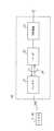
図2は、認識装置20の構成例を示すブロック図である。
同図に示すように、認識装置20は、ICタグ11との間で無線通信を行うためのアンテナ21(アンテナ部の一例、アンテナセットの一例)と、アンテナ21により受信されたICタグ11の個別データを読み取るリーダ22と、を備えている。また、認識装置20は、リーダ22により読み取られた個別データがコンテナ12に作業員15(図1参照)が積み込もうとしている手荷物10(図1参照)のものか否かを判定する判定装置23を備えている。
アンテナ21は、同軸ケーブル24によりリーダ22と接続されている。アンテナ21は、同軸ケーブル24を介してリーダ22から給電され、その電力を用いて電波を発信する。そして、アンテナ21は、ICタグ11の電波を受信すると同軸ケーブル24を介してリーダ22に送る。アンテナ21の具体的な構成は後述する。FIG. 2 is a block diagram illustrating a configuration example of the
As shown in the figure, the
The
リーダ22は、アンテナ21が受信した電波を受け取ると、所定の手順に沿って処理を行う。すなわち、リーダ22は、電波の周波数の変換を行い、デジタルデータを取り出し、それを通信プロトコルに基づき解釈する。リーダ22は、読み取った個別データを判定装置23に送る。なお、リーダ22は、アンテナ21の読み取り可能範囲(アクセス範囲、受信範囲)にICタグ11が入ったら自動的に読み取りする非同期型である。
判定装置23は、例えば、ソフトウェアを実行して所定の演算等を行うコンピュータ本体、ディスプレイ等の表示装置、コンピュータ本体に対して入力を行うための入力装置等により構成される。この判定装置23としては、例えば、パーソナルコンピュータやワークステーション、その他のコンピュータが用いられる。判定装置23の具体的な構成は後述する。When the
The
図3は、認識装置20が備えるアンテナ21の指向性を説明する図である。同図の(a)は、アンテナ21の読み取り可能範囲を示す、アンテナ面33,34と交差する方向の縦断面図であり、(b)は、(a)の線IIIb-IIIbによる横断面図である。(c)は、アンテナ21の一部を構成するアンテナ31の読み取り可能範囲を示す縦断面図であり、(d)は、アンテナ21の一部を構成する他のアンテナ32の読み取り可能範囲を示す縦断面図である。
同図の(a)に示すように、認識装置20のアンテナ21は、アンテナ31(第1のアンテナの一例、第2の受信部の一例)及びアンテナ32(第2のアンテナの一例、第1の受信部の一例)を備えている。アンテナ31はパッチアンテナで構成され、また、アンテナ32は、パッチアンテナで構成されている。このパッチアンテナは、電波を放射する放射板と、誘電材料からなる誘電体と、放射板に対応する地板と、を有する。なお、面アンテナとしてのパッチアンテナの代わりに、RFIDの通信が可能な他のアンテナ、例えば線状アンテナとしてのダイポールアンテナを用いることも考えられる。FIG. 3 is a diagram illustrating the directivity of the
As shown to (a) of the figure, the
アンテナ31は同軸ケーブル24(図2参照)を介して給電を受けると、放射板のアンテナ面33から電波を放射する。アンテナ32は同軸ケーブル24を介して給電を受けると、放射板のアンテナ面34から電波を放射する。アンテナ21は、アンテナ31のアンテナ面33とアンテナ32のアンテナ面34とが互いに同じ方向に向くように構成されている。なお、読み取り可能な範囲は、アンテナ面33,34から最大で5m程度の距離である。
アンテナ21は、アンテナ31とアンテナ32の双方で読み取り可能な範囲と、アンテナ31のみで読み取り可能な範囲と、を有する。When the
The
同図の(c)及び(d)に示すように、アンテナ31の指向性とアンテナ32の指向性とは互いに異なる。すなわち、アンテナ31は、同図の(c)に示すように、アンテナ面33の鉛直方向に最大ゲインがあるような指向性を有する。また、アンテナ32は、同図の(d)に示すように、アンテナ面34の鉛直方向がNULL(ゲインが低い)になる指向性を有する。NULL点は1箇所である。なお、アンテナ32の構成例としては、2素子のパッチアンテナが考えられる。すなわち、2素子の一方の素子には同軸ケーブル24(図2参照)から給電し、他方の素子には位相を反転させて給電することでアンテナ32の指向性が実現される。
このように、指向性が互いに異なる2つのアンテナ31,32を一つのアンテナ21としている。すなわち、アンテナ21は、指向性が互いに異なるアンテナ31,32を一組のRFID用アンテナとして動作するように構成されている。
更に説明すると、アンテナ21は、同図の(b)に示すように、アンテナ31の読み取り可能範囲であると共にアンテナ32の読み取り可能範囲でもある第1の領域(受信範囲)35と、アンテナ31の読み取り可能範囲である第2の領域(受信範囲)36と、アンテナ31の読み取り可能範囲でないと共にアンテナ32の読み取り可能範囲でもない第3の領域(非受信範囲)37と、を有する。本実施の形態のアンテナ21は、第1の領域35が第2の領域36を挟むように配置される断面を有する。
アンテナ21は、このようにして組み合わせたアンテナ31,32が一組として動作するように構成されている。As shown in FIGS. 3C and 3D, the directivity of the
Thus, the two
More specifically, the
The
なお、本実施の形態では、アンテナ21は、ICタグ11の読み取り可能範囲として、上述した第1の領域35と第2の領域36とを組み合わせた構成であるが、他の構成も考えられる。すなわち、アンテナ21は、アンテナ31の読み取り可能範囲である領域と、アンテナ32の読み取り可能範囲である領域と、アンテナ31の読み取り可能範囲であると共にアンテナ32の読み取り可能範囲でもある領域のうち、いずれか2つの領域又は3つの領域を形成するように構成することが考えられる。 In the present embodiment, the
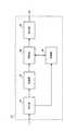
図4は、認識装置20が備える判定装置23の構成例を示すブロック図である。
同図に示すように、判定装置23は、リーダ22(図2参照)から所定のデータを受け付ける受付部41と、受付部41が受け付けたデータ等を記憶する記憶部42と、受け付けたデータが意図的に読み込ませられたICタグ11(図1又は図2参照)のものか否かを判定する判定部43と、を備えている。また、判定装置23は、受付部41からの指示に従って経過時間を計時し、その計時結果としての経過時間の情報を判定部43に送る計時部44と、判定部43の判定結果を出力する出力部45と、を備えている。FIG. 4 is a block diagram illustrating a configuration example of the
As shown in the figure, the
受付部41は、リーダ22がICタグ11を検出したことを受け付ける。また、受付部41は、検出したICタグ11の個別データと、そのICタグ11を受信したアンテナ31,32の情報と、を受け付ける。
記憶部42は、受付部41により受け付けられたデータを記憶し、記憶しているデータを受付順に判定部43に送る。The accepting
The
判定部43は、記憶部42から送られたデータ及び計時部44から送られたデータを基に、一連のICタグ11の検出が所定の内容で規定の時間内に行われたか否かを判別する。そして、判定部43は、判別の結果から、検出したICタグ11は作業者15(図1参照)により意図的に読み込ませられたものと判定する。判定部43は、そのように判定すると、判定結果及びICタグ11の個別データを出力部45に送る。なお、判定部43は、予め定められた動作制御プログラム(ファームウェアまたはアプリケーションプログラム)に従ってデジタル演算処理を実行する図示しないCPU(Central Processing Unit)と、CPUの作業用メモリ等として機能すると共にCPUにより実行される処理プログラムや処理プログラムにて用いられる設定値等のデータ等が格納されるメモリと、で構成することが考えられる。このメモリは、例えばフラッシュメモリ、EEPROMなどで構成することができる。
出力部45は、判定部43から送られたデータを外部に出力する。Based on the data sent from the
The
図5は、判定装置23が備える判定部43による判定を説明するための図である。(a)はアンテナ31,32の読み取り可能範囲とICタグ11との位置関係を説明する図であり、(b)は意図的な読み込みの判定を行う場合の条件を説明する表である。
同図の(a)に示すように、ICタグ11を取り付けた手荷物10が作業員15(図1参照)によりコンテナ12の扉開口部13から積み込まれるときには、ICタグ11は、位置51、位置52、位置53及び位置54の順で、アンテナ31,32の読み取り可能範囲内を進行する。更に説明すると、位置51及び位置53では、ICタグ11はアンテナ31により読み取られると共にアンテナ32により読み取られる状態である。位置52では、ICタグ11はアンテナ31により読み取られる一方でアンテナ32により読み取られない状態である。位置54では、ICタグ11はアンテナ31により読み取られず、かつ、アンテナ32により読み取られない状態である。なお、位置51及び位置53は、図3に示す第1の領域35内にあり、位置52は、第2の領域36内にあり、位置54は、第3の領域37にある。FIG. 5 is a diagram for explaining determination by the
As shown in (a) of the figure, when the
したがって、判定部43は、アンテナ31とアンテナ32の受信状況(読み取りの有無)を監視することで、ICタグ11が保持する情報をリーダ22に読み取らせるために作業員15が意図的にICタグ11をアンテナ21にかざす行為をし、その結果としてリーダ22がその情報を読み取ったものであるとの判定(意図的な読み込みとの判定)を行うことができる。すなわち、図5の(b)に示すように、まず、第1段階としてアンテナ31,32によりICタグ11が読み取られる。そして、第2段階は、アンテナ31のみによりICタグ11が読み取られる。次の第3段階では、アンテナ31,32によりICタグ11が読み取られる。その後、第4段階では、アンテナ31,32によりICタグ11が読み取られない。
このようなアンテナ31,32の一連の受信状況の変化を監視することにより、ICタグ11が誤って認識されてしまう事態を防止することが可能になる。Therefore, the
By monitoring such changes in the reception status of the
付言すると、第1段階におけるアンテナ21の受信態様としては、アンテナ31,32で受信される態様であり、第2段階におけるアンテナ21の受信態様としては、アンテナ31で受信される態様である。また、第3段階におけるアンテナ21の受信態様としては、アンテナ31,32で受信される態様である。そして、第4段階では、アンテナ31,32で受信されない態様である。
なお、第1段階から第3段階までの受信態様として他の受信態様となるように、アンテナ21を構成することも考えられる。また、本実施の形態では、4つの段階であるが、他の数の段階となるようにアンテナ21を構成することも考えられる。In addition, the reception mode of the
Note that it is also conceivable to configure the
また、図5の(a)に示すように、ICタグ11が位置51から位置54に移動するまでの時間tを監視することで、更にICタグ11の誤認識を防止することが可能になる。例えば、アンテナ21の読み取り可能範囲の設定がコンテナ12の扉開口部13(図1参照)に対して正確に行われていない場合には、作業員15(図1参照)が意図しないICタグ11の一連の読み取りがなされることが想定される。より具体的には、コンテナ12に積み込む前に取り置きしている手荷物10(図1参照)が複数あるために、手荷物10をずらしたり別の場所に移動したりすることで、たまたま図5の(b)に示す順序で一連の読み取りが行われてしまうことが考えられる。
このような事態が発生しても、時間tが規定の時間内でなければ、判定部43は、意図的に読み込ませたと判定しない。ここにいう規定の時間としては、作業員15が手荷物10をコンベア14から持ち上げ、その手荷物10をコンテナ12の扉開口部13からコンテナ12内部に積み込むまでに要する一般的な時間である。この規定の時間は、記憶部42に予め記憶され、必要に応じて読み出される。また、規定の時間は、状況に応じて任意に設定することも考えられる。Further, as shown in FIG. 5A, by monitoring the time t until the
Even if such a situation occurs, if the time t is not within the specified time, the
図6は、判定装置23での処理手順を示すフローチャートである。
同図に示すフローチャートでは、判定装置23は、リーダ22(図2参照)からICタグ11の個別データを取得することによりICタグ11を検知する(ステップ101)。すなわち、受付部41(図4参照)がリーダ22からICタグ11の個別データを、そのICタグ11を受信したアンテナの情報と共に受け付ける。判定部43(図4参照)は、その個別データ及びアンテナの情報を受け取ることにより、ICタグ11を検知する。このようにして検知されたICタグ11を、説明の便宜のために以下、ICタグ61と呼ぶ。
付言すると、判定装置23は、受け取ったアンテナの情報により、ICタグ61の位置を把握することができる。すなわち、受け取ったアンテナの情報がアンテナ31,32のものであれば、判定装置23は、ICタグ61が位置51又は位置53(図5の(a)参照)に位置していると把握することができる。また、受け取ったアンテナの情報がアンテナ31のみのものであれば、判定装置23は、ICタグ61が位置52(図5の(a)参照)に位置していると把握することができる。FIG. 6 is a flowchart showing a processing procedure in the
In the flowchart shown in the figure, the
In other words, the
その後、受付部41は計時部44に計時の開始を指示し、計時部44は計時を開始し(ステップ102)、経過時間を計時する。計時部44は、経過時間を所定のタイミングで判定部43に送る。受付部41は、リーダ22から送られてくるデータを記憶部42(図4参照)に送る。記憶部42は、受付部41から送られた個別データ及びアンテナの情報を記憶し、また、その個別データ及びアンテナの情報を判定部43に逐次送る。 Thereafter, the
判定部43は、ICタグ61についてアンテナ31,32での読み取りがあるか否かを判断する(ステップ103)。すなわち、判定部43は、ICタグ61がアンテナ31及びアンテナ32で読み取られたか否かを判断する。言い換えると、ICタグ61からの電波をアンテナ31とアンテナ32の両方で受信したか否かを判断する。その判断は、個別データに含まれるICタグ61のID情報を用いて行われる。ステップ103での判断を実行することにより、アンテナ31とアンテナ32のいずれか一方でICタグ61が誤って読み取られた場合に対処することができる。 The
ステップ103において、判定部43は、アンテナ31,32のいずれか一方でICタグ61からの電波を受信したと判断すると、計時部44に計時の終了を指示し、計時部44は計時を終了する(ステップ104)。また、判定部43は、ICタグ61の個別データは意図的に読み込まれたものではないと判定する(ステップ105)。なお、判定部43は、意図的な読み込みではないとの判定結果を出力部45に出力しなくても良く、出力しても良い。 In step 103, when the
ステップ103において、判定部43は、アンテナ31で受信したICタグ61とアンテナ32で受信したICタグ61とが互いに同一であると判断すると、そのICタグ61のアンテナ31,32による受信状況の変化を監視する。ICタグ61が取り付けられた手荷物10(図1参照)が動かされることにより、ICタグ61のアンテナ31,32の受信状況が変化する。
判定部43は、ICタグ61のアンテナ31のみの読み取りがあるか否かを判断する(ステップ106)。すなわち、判定部43は、ICタグ61が今度はアンテナ31だけで読み取られたか否かを判断する。この判断を行うことによって、判定部43は、図5の(a)に示す位置51から位置52へ移行したか否かを把握することができる。In step 103, when the
The
ステップ106において、判定部43は、ICタグ61についてアンテナ31のみの読み取りがないと判断すると、経過時間の情報を計時部44から取得し、ICタグ61を検知した時点から所定の時間が経過したか否かを判断する(ステップ107)。判定部43は、所定時間が経過していないと判断するとステップ106に戻り、経過したと判断すると、ステップ104に進む。ステップ106及びステップ107の判断を実行することにより、コンベア14からコンテナ12に直ちに積み込むのではなく、いったん取り置いた手荷物10(図1参照)のICタグ61がアンテナ31,32の両方で誤って読み取られた場合に対処することができる。
なお、ここにいう所定の時間としては、作業員15(図1参照)が手に持っている手荷物10(図1参照)をコンテナ12(図1参照)の内部に移動させる時間、例えば5秒である。その所定の時間の情報は、記憶部42に予め記憶されている。In step 106, when the
The predetermined time here is a time for moving the baggage 10 (see FIG. 1) held by the worker 15 (see FIG. 1) into the container 12 (see FIG. 1), for example, 5 seconds. It is. Information on the predetermined time is stored in advance in the
ステップ106において、判定部43は、ICタグ61についてアンテナ31のみの読み取りがあると判断すると、ICタグ61についてアンテナ31,32での読み取りがあるか否かを判断する(ステップ108)。この判断によって、判定部43は、図5の(a)に示す位置52から位置53へ移行したか否かを把握することができる。
なお、判定部43は、ICタグ61がアンテナ31,32での読み取りがないと判断すると、ステップ104に進む。If it is determined in step 106 that the IC tag 61 is read only by the
If the
ステップ108において、判定部43は、ICタグ61がアンテナ31,32の両方で読み取られたと判断すると、ICタグ61についてアンテナ31,32での読み取り不可があるか否かを判断する(ステップ109)。この判断によって、判定部43は、図5の(a)に示す位置53から位置54へ移行したか否かを把握することができる。
なお、判定部43は、ICタグ61がアンテナ31,32での読み取り不可がないと判断すると、ステップ104に進む。If the
If the
ステップ109において、判定部43は、ICタグ61がアンテナ31,32での読み取り不可があると判断すると、計時部44に計時の終了を指示し、計時部44は計時を終了する(ステップ110)。その後、判定部43は、計時部44から経過時間の情報を取得する。判定部43は、経過時間の情報を基に、図5の(a)に示す位置51から位置54までに移行する時間が規定の時間内か否かを判断する(ステップ111)。なお、規定の時間の情報は、記憶部42に記憶されている。 In step 109, when the
ステップ111において、判定部43は、規定の時間内であると判断すると、ICタグ61は意図的に読み込まれたと判定する(ステップ112)。判定部43は、規定の時間内ではないと判断すると、ステップ105に進む。このようにして、一連の処理手順を終了する。 In step 111, when the
このように、判定部43は、次の条件をすべて満たすことを条件に、作業者15(図1参照)がICタグ61を意図的に読み込ませようとする行為によりICタグ61の読み取りがなされたものであることを判定する。その第1の条件は、ICタグ61が、2つのアンテナ31,32(図3参照)で読み取られ、次に、アンテナ31だけで読み取られ、最後に2つのアンテナ31,32で読み取られた後に、2つのアンテナ31,32で読み取られないことというゾーンシーケンスである。第2の条件は、第1の条件の具備が規定の時間内で完了したことである。 As described above, the
更に説明すると、本実施の形態ではゾーンシーケンスで作業者15(図1参照)の意向を判断している。すなわち、本実施の形態では、ICタグ61を意図的に読み込ませているかを認識装置20に判断させるために、RFIDアンテナとして指向性の異なる2つのアンテナ31,32を用いている。アンテナ31は通常のパッチアンテナであり、アンテナ面33の鉛直方向に最大ゲインがある。もう1つのアンテナ32は、アンテナ面34の鉛直方向がNULLになっている。この2つのアンテナ31,32を1組としてRFIDのアンテナ21として動作させる。 More specifically, in this embodiment, the intention of the worker 15 (see FIG. 1) is determined by a zone sequence. That is, in the present embodiment, two
ICタグ61が、ある方向からアンテナ21の照射エリアに入ってくると、これらの2つのアンテナ31,32に認識される(図5の(a)での位置51)。ICタグ61が移動してアンテナ21の中央(鉛直方向付近)になったときにはアンテナ31には認識されるが、もう1つのアンテナ32には認識されない(図5の(a)での位置52)。ICタグ61がさらに移動すると、また2つのアンテナ31,32に認識され(図5の(a)での位置53)、最後には2つのアンテナ31,32が認識できないエリアに出る(図5の(a)での位置54)。これら一連の認識が規定の時間内に完了したら、認識装置20は、作業者15(図1参照)が意図的に読み込ませたと判断する。 When the IC tag 61 enters the irradiation area of the
また更に説明すると、RFIDは電波方式を採用するが、ICタグ11の誤認識を防止するために、電波の受信範囲を狭くすると使い勝手が低下してしまう。本実施の形態のようなゾーンシーケンスにより、ユーザの意図を反映した処理を行うことができる。 Further, although the RFID employs a radio wave system, the usability is reduced if the radio wave reception range is narrowed in order to prevent erroneous recognition of the
本実施の形態についての種々の変形例が考えられる。
図7は、本実施の形態に用いる他のアンテナ25の指向性を説明する図である。(a)は、アンテナ31,38の読み取り可能範囲とICタグ11との位置関係を説明する図であり、(b)は意図的な読み込みの判定を行う場合の条件を説明する表である。
同図の(a)に示すアンテナ25は、認識装置20の一部を構成するアンテナ21(図2参照)の代わりに用いるものである。このアンテナ25は、複数のアンテナ31,38を備えている。アンテナ38は、アンテナ31,32と同様にパッチアンテナである。アンテナ38は、アンテナ32と同様に、アンテナ面の鉛直方向がNULLになる指向性を有する。NULL点は2箇所である。
ICタグ11を取り付けた手荷物10が作業員15(図1参照)によりコンテナ12の扉開口部13から積み込まれるときには、ICタグ11は、位置71、位置72、位置73、位置74、位置75及び位置76の順で、アンテナ31,38の読み取り可能範囲内を進行する。Various modifications of the present embodiment can be considered.
FIG. 7 is a diagram illustrating the directivity of another
An
When the
したがって、図7の(b)に示すように、アンテナ31,38によりICタグ11が読み取られる段階と、アンテナ31によりICタグ11が読み取られる段階と、を複数回繰り返したときに、ICタグ11が意図的な読み込みと判定することができる。このように、アンテナ25を用いると、アンテナ21を用いる場合よりも判定の確度を向上させることができる。 Accordingly, as shown in FIG. 7B, when the
本実施の形態を他のシステムに適用することも考えられる。
図8は、本実施の形態を適用した移動方向認識システムTを説明する概略平面図である。なお、移動方向認識システムTは、上述した手荷物管理システムS(図1参照)と共通する構成を備えているので、同じ構成には同じ符合を用い、その説明を省略することがある。
図8に示す移動方向認識システムTは、移動体(例えば人間や被搬送物品)が通路81から通路82に移動したか又は通路83に移動したかを認識するために使用されるものである。通路81から通路82,83に分岐する位置付近には、アンテナ21及びアンテナ26が設置されている。アンテナ26は、アンテナ21のアンテナ31,32と同じくパッチアンテナである。アンテナ26は、アンテナ31と同じく、アンテナ面の鉛直方向に最大ゲインがあるような指向性を有する。It is also conceivable to apply this embodiment to other systems.
FIG. 8 is a schematic plan view for explaining a moving direction recognition system T to which the present embodiment is applied. In addition, since the movement direction recognition system T has the same configuration as the above-described baggage management system S (see FIG. 1), the same reference numerals are used for the same configurations and the description thereof may be omitted.
A moving direction recognition system T shown in FIG. 8 is used for recognizing whether a moving body (for example, a person or an article to be conveyed) has moved from the
移動体が通路81から通路82に移動するときには、位置91、位置92、位置93及び位置94の順で、アンテナ31,32の読み取り可能範囲内を進む。また、移動体が通路81から通路83に移動するときには、位置91、位置95及び位置96の順で、アンテナ31,32,26の読み取り可能範囲内を進む。
移動体にICタグ11が取り付けられていれば、移動体が位置91,93を移動する際には、アンテナ31,32によりICタグ11が読み取られる。移動体が位置92を移動する際には、アンテナ31によりICタグ11が読み取られる。移動体が位置94,96を移動する際には、アンテナ31,32,26のいずれにもICタグ11が読み取られない。移動体が位置95に移動する際には、アンテナ26によりICタグ11が読み取られる。When the moving body moves from the
If the
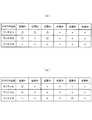
図9は、移動体の移動方向の判定を行う場合の条件を説明する表である。(a)は、通路81,82を通る場合の読み取り条件を説明する表であり、(b)は、通路81,83を通る場合の読み取り条件を説明する表である。
同図の(a)に示すように、移動体が通路81,82を通る場合には、アンテナ26によりICタグ11が読み取られない。すなわち、位置91では、アンテナ31,32によりICタグ11が読み取られる。位置92では、アンテナ31によりICタグ11が読み取られる。位置93では、アンテナ31,32によりICタグ11が読み取られる。位置94では、アンテナ31,32のいずれにもICタグ11が読み取られない。
このような読み取りが順に行われるときには、移動体は、通路81から通路82を通ったとの判定を行うことができる。FIG. 9 is a table for explaining the conditions for determining the moving direction of the moving body. (A) is a table explaining reading conditions when passing through the
As shown to (a) of the figure, when a mobile body passes the channel |
When such reading is performed in order, the moving body can determine that the
同図の(b)に示すように、移動体が通路81,83を通る場合には、位置91では、アンテナ31,32によりICタグ11が読み取られる。位置95では、アンテナ26によりICタグ11が読み取られる。位置96では、アンテナ26によりICタグ11が読み取られない。
このような読み取りが順に行われるときには、移動体は、通路81から通路83を通ったとの判定を行うことができる。As shown in FIG. 5B, when the moving body passes through the
When such reading is performed in order, the moving body can determine that the
10…手荷物、11,61…ICタグ、20…認識装置、21,25,26,31,32,38…アンテナ、22…リーダ、23…判定装置、35…第1の領域、36…第2の領域、37…第3の領域、41…受付部、42…記憶部、43…判定部、44…計時部、45…出力部、S…手荷物管理システム、T…移動方向認識システムDESCRIPTION OF
Claims (7)
Translated fromJapanese前記ICタグからの電波を受信する第1のアンテナ及び第2のアンテナを備え、当該第1のアンテナによる読み取り可能な範囲である領域と、当該第2のアンテナによる読み取り可能な範囲である領域と、当該第1のアンテナ及び当該第2のアンテナによる読み取り可能な範囲である領域と、のうち少なくともいずれか2つの領域を組み合わせてなる複数の領域を形成するように構成されるアンテナ部と、
前記アンテナ部を介して前記ICタグの前記情報を読み取る読み取り部と、
前記複数の領域にて最初に前記ICタグの前記情報が読み取られてからの経過時間を計時する計時部と、
前記複数の領域での前記第1のアンテナ及び前記第2のアンテナを介する前記情報の読み取りの有無および前記計時部による経過時間に基づいて、前記読み取り部に当該情報を読み取らせるための行為により当該読み取り部が読み取ったものか否かを判定し、かつ、当該計時部による経過時間が予め定められる値を超える場合に当該行為により当該読み取り部が読み取ったものではないと判定する判定部と、
を含む、装置。An apparatus for recognizing information held by an IC tag,
A first antenna and a second antenna that receive radio waves from the IC tag, an area that is readable by the first antenna, and an area that is readable by the second antenna; An antenna unit configured to form a plurality of regions formed by combining at least any two of the first antenna and the region that is a readable range by the second antenna;
A reading unit that reads the information of the IC tag through the antenna unit;
A timing unit that counts an elapsed time since the information of the IC tag was first read in the plurality of areas;
Based on the presence/ absence of reading of the information via the first antenna and the second antenna in the plurality of regions and theelapsed time by the timing unit , the act of causing the reading unit to read the information a determination unitwhich determines whether or not the reading unit hasread, and isdetermined not to be construed the reading unit is read by the act when it exceeds the value over time by the timing unit is determined in advance,
Including the device.
第1の領域に位置する前記ICタグから前記情報が、第1のアンテナと第2のアンテナのいずれか一方又は両方のうち予め定められたアンテナで受信される受信態様で読み取られたか否かを判断するステップと、
前記第1の領域の外である第2の領域に位置する前記ICタグから前記情報が、当該第1の領域での前記受信態様とは異なる予め定められた別の受信態様で読み取られたか否かを判断するステップと、
前記受信態様での読み取りと前記別の受信態様での読み取りのうち最初に前記ICタグの前記情報が読み取られてからの経過時間を計時するステップと、
前記第1の領域の外であると共に前記第2の領域の外でもある第3の領域に位置する前記ICタグから前記情報が、前記第1のアンテナ及び前記第2のアンテナで読み取り不可であるか否かを判断するステップと、
前記第1の領域にて前記受信態様で読み取りがなされたこと、前記第2の領域にて前記別の受信態様で読み取りがなされたこと及び前記第3の領域にて読み取り不可であること並びに計時される前記経過時間を条件に、前記ICタグの前記情報を読み取らせるための行為により当該情報を読み取ったものか否かを判定し、かつ、当該経過時間が予め定められる値を超える場合に当該行為により読み取ったものではないと判定するステップと、
を含む、方法。A method for recognizing information held by an IC tag,
Whether or not the information is read from the IC tag located in the first area in a reception mode in which the information is received by a predetermined antenna of one or both of the first antenna and the second antenna. A step of judging;
Whether the information has been read from the IC tag located in the second area outside the first area in another predetermined reception manner different from the reception manner in the first area. A step of determining whether or not
Measuring the time elapsed since the information of the IC tag was first read out of the reading in the reception mode and the reading in the other reception mode;
The information is not readable by the first antenna and the second antenna from the IC tag located in the third area that is outside the first area and outside the second area. Determining whether or not,
Reading in the reception mode in the first area, reading in the other reception mode in the second area, reading in the third area, and timing on conditionthe elapsed time being, whether or not read the informationdetermined by the act for reading the information of the ICtag, and the if it exceeds a value which the elapsed time is predetermined a step ofdetermining and not as read by the act,
Including a method.
Priority Applications (2)
| Application Number | Priority Date | Filing Date | Title |
|---|---|---|---|
| JP2008178940AJP5243868B2 (en) | 2008-07-09 | 2008-07-09 | Apparatus and method for recognizing information held by IC tag |
| US12/498,669US9949001B2 (en) | 2008-07-09 | 2009-07-07 | Apparatus and method for recognizing information held by an IC tag |
Applications Claiming Priority (1)
| Application Number | Priority Date | Filing Date | Title |
|---|---|---|---|
| JP2008178940AJP5243868B2 (en) | 2008-07-09 | 2008-07-09 | Apparatus and method for recognizing information held by IC tag |
Publications (2)
| Publication Number | Publication Date |
|---|---|
| JP2010020455A JP2010020455A (en) | 2010-01-28 |
| JP5243868B2true JP5243868B2 (en) | 2013-07-24 |
Family
ID=41504652
Family Applications (1)
| Application Number | Title | Priority Date | Filing Date |
|---|---|---|---|
| JP2008178940AActiveJP5243868B2 (en) | 2008-07-09 | 2008-07-09 | Apparatus and method for recognizing information held by IC tag |
Country Status (2)
| Country | Link |
|---|---|
| US (1) | US9949001B2 (en) |
| JP (1) | JP5243868B2 (en) |
Families Citing this family (5)
| Publication number | Priority date | Publication date | Assignee | Title |
|---|---|---|---|---|
| US10289877B2 (en)* | 2013-09-23 | 2019-05-14 | Hand Held Products, Inc. | Directional antenna for RFID tag finder |
| US11230390B2 (en)* | 2018-01-04 | 2022-01-25 | E-Business Solutions Limited | Baggage recording system |
| US10930102B2 (en)* | 2019-02-15 | 2021-02-23 | Nec Corporation | Method for employing a RFID walk-through gate |
| US11030429B2 (en)* | 2019-09-11 | 2021-06-08 | RadicalID, Inc. | Multipurpose RFID transponder and a system for reading it |
| US11790191B2 (en) | 2019-09-11 | 2023-10-17 | RadicalID, Inc. | Multipurpose RFID transponder and a system for reading it |
Family Cites Families (14)
| Publication number | Priority date | Publication date | Assignee | Title |
|---|---|---|---|---|
| US4639716A (en)* | 1984-11-19 | 1987-01-27 | Ici Americas Inc. | Alarm packet system |
| JP2894002B2 (en)* | 1991-06-06 | 1999-05-24 | 株式会社デンソー | Electronic Tag Interrogation Device |
| JP3533966B2 (en)* | 1998-06-18 | 2004-06-07 | トヨタ自動車株式会社 | Vehicle control system |
| JP2000113125A (en) | 1998-10-06 | 2000-04-21 | Toshiba Corp | Wireless card processing device and wireless card processing system |
| US6703935B1 (en)* | 2001-05-14 | 2004-03-09 | Amerasia International Technology, Inc. | Antenna arrangement for RFID smart tags |
| WO2002103645A2 (en)* | 2001-06-14 | 2002-12-27 | Rf Code, Inc. | Wireless identification system and protocol |
| JP2003146413A (en)* | 2001-11-16 | 2003-05-21 | Nippon Telegr & Teleph Corp <Ntt> | Lending / return management method using wireless tag and device for implementing the method |
| KR100537545B1 (en) | 2003-05-31 | 2005-12-16 | 매그나칩 반도체 유한회사 | Method for operating organic light emitted dipslay pannel |
| FR2865811B1 (en)* | 2004-01-30 | 2007-01-26 | Neopost Ind | DEVICE FOR DETECTING THE DIRECTION OF PASSING AN OBJECT TO A DETERMINED FRONTIER ZONE |
| JP4244859B2 (en)* | 2004-05-10 | 2009-03-25 | 株式会社Ihi | Inspection device and inspection method for truck load |
| US7492259B2 (en)* | 2005-03-29 | 2009-02-17 | Accu-Sort Systems, Inc. | RFID conveyor system and method |
| US7380723B1 (en)* | 2005-11-01 | 2008-06-03 | Hewlett-Packard Development Company, L.P. | Monitoring object movement |
| JP4876034B2 (en)* | 2007-06-29 | 2012-02-15 | 株式会社日立製作所 | Article movement management system and article movement management method |
| DE102007030738A1 (en)* | 2007-07-02 | 2009-01-08 | Sick Ag | Reading information with optoelectronic sensor and RFID reader |
- 2008
- 2008-07-09JPJP2008178940Apatent/JP5243868B2/enactiveActive
- 2009
- 2009-07-07USUS12/498,669patent/US9949001B2/enactiveActive
Also Published As
| Publication number | Publication date |
|---|---|
| US9949001B2 (en) | 2018-04-17 |
| JP2010020455A (en) | 2010-01-28 |
| US20100007468A1 (en) | 2010-01-14 |
Similar Documents
| Publication | Publication Date | Title |
|---|---|---|
| US8606174B2 (en) | Portable radio-frequency repeater | |
| US9026041B2 (en) | Portable radio-frequency repeater | |
| US7195159B2 (en) | Radio frequency identification (RFID) material tracking and apparatus | |
| JP5243868B2 (en) | Apparatus and method for recognizing information held by IC tag | |
| US10053233B2 (en) | Device and a method for automatic detection of whether an item is correctly routed | |
| JP6641245B2 (en) | Luggage management system | |
| JP2017019588A (en) | COMMUNICATION DEVICE, CARRYING AUXILIARY DEVICE AND CARRYING SYSTEM | |
| CN104438094B (en) | Intelligent sorting and transporting system of airport arrival baggage and control method | |
| US7183916B2 (en) | Method for identifying packages in transit | |
| US11348427B2 (en) | Active RFID tag and product surveillance method | |
| CN101778784A (en) | Inspection system | |
| JP2000122720A (en) | Inspection and transport method for unmanned guided vehicles | |
| JP2002207079A (en) | Article detecting system | |
| EP2050048A1 (en) | System for managing and controlling the movement of people and/or goods inside of equipped areas | |
| JP6164703B2 (en) | Work results collection system, work results collection method and program | |
| JP6889768B2 (en) | Luggage management device | |
| WO2006095827A1 (en) | Information processing device, management system, information processing device control program, and recording medium containing the information processing device control program | |
| KR20230057598A (en) | Automatic sorting of air baggage delivery system and air baggage delivery method using the system | |
| JP2002205820A (en) | Loading inspection system | |
| JP2020142869A (en) | ID tag information reading system | |
| JP5128802B2 (en) | Aircraft container | |
| JP2005031924A (en) | Reader/writer | |
| JP2005035716A (en) | Physical distribution management system | |
| JP2008184329A (en) | Method for carrying out inspected item in automated guided vehicle | |
| JP2019003514A (en) | Information processing apparatus and information processing method |
Legal Events
| Date | Code | Title | Description |
|---|---|---|---|
| A621 | Written request for application examination | Free format text:JAPANESE INTERMEDIATE CODE: A621 Effective date:20110608 | |
| A977 | Report on retrieval | Free format text:JAPANESE INTERMEDIATE CODE: A971007 Effective date:20121101 | |
| A131 | Notification of reasons for refusal | Free format text:JAPANESE INTERMEDIATE CODE: A131 Effective date:20121204 | |
| A521 | Written amendment | Free format text:JAPANESE INTERMEDIATE CODE: A523 Effective date:20130301 | |
| TRDD | Decision of grant or rejection written | ||
| RD14 | Notification of resignation of power of sub attorney | Free format text:JAPANESE INTERMEDIATE CODE: A7434 Effective date:20130319 | |
| A01 | Written decision to grant a patent or to grant a registration (utility model) | Free format text:JAPANESE INTERMEDIATE CODE: A01 Effective date:20130319 | |
| A61 | First payment of annual fees (during grant procedure) | Free format text:JAPANESE INTERMEDIATE CODE: A61 Effective date:20130405 | |
| FPAY | Renewal fee payment (event date is renewal date of database) | Free format text:PAYMENT UNTIL: 20160412 Year of fee payment:3 | |
| R150 | Certificate of patent or registration of utility model | Free format text:JAPANESE INTERMEDIATE CODE: R150 Ref document number:5243868 Country of ref document:JP Free format text:JAPANESE INTERMEDIATE CODE: R150 |