JP5242221B2 - Imaging apparatus, electronic endoscope, and assembling method of imaging apparatus - Google Patents
Imaging apparatus, electronic endoscope, and assembling method of imaging apparatusDownload PDFInfo
- Publication number
- JP5242221B2 JP5242221B2JP2008092647AJP2008092647AJP5242221B2JP 5242221 B2JP5242221 B2JP 5242221B2JP 2008092647 AJP2008092647 AJP 2008092647AJP 2008092647 AJP2008092647 AJP 2008092647AJP 5242221 B2JP5242221 B2JP 5242221B2
- Authority
- JP
- Japan
- Prior art keywords
- objective lens
- solid
- imaging device
- state imaging
- frame
- Prior art date
- Legal status (The legal status is an assumption and is not a legal conclusion. Google has not performed a legal analysis and makes no representation as to the accuracy of the status listed.)
- Expired - Lifetime
Links
- 238000003384imaging methodMethods0.000titleclaimsdescription118
- 238000000034methodMethods0.000titleclaimsdescription8
- 230000002093peripheral effectEffects0.000claimsdescription49
- 230000003287optical effectEffects0.000claimsdescription45
- 239000006059cover glassSubstances0.000claimsdescription12
- 238000003780insertionMethods0.000description10
- 230000037431insertionEffects0.000description10
- 238000005286illuminationMethods0.000description5
- 238000005452bendingMethods0.000description4
- 230000007547defectEffects0.000description4
- 238000010586diagramMethods0.000description4
- 230000001681protective effectEffects0.000description4
- 239000000853adhesiveSubstances0.000description3
- 230000001070adhesive effectEffects0.000description3
- 239000007787solidSubstances0.000description3
- 239000012530fluidSubstances0.000description2
- 239000011521glassSubstances0.000description2
- 230000012447hatchingEffects0.000description2
- 239000000696magnetic materialSubstances0.000description2
- 239000000463materialSubstances0.000description2
- 238000007789sealingMethods0.000description2
- 230000000007visual effectEffects0.000description2
- XLYOFNOQVPJJNP-UHFFFAOYSA-NwaterSubstancesOXLYOFNOQVPJJNP-UHFFFAOYSA-N0.000description2
- 229910001369BrassInorganic materials0.000description1
- 239000004593EpoxySubstances0.000description1
- 239000010951brassSubstances0.000description1
- 239000006185dispersionSubstances0.000description1
- 230000000694effectsEffects0.000description1
- 238000001727in vivoMethods0.000description1
- 239000007788liquidSubstances0.000description1
- 238000004519manufacturing processMethods0.000description1
- 238000012986modificationMethods0.000description1
- 230000004048modificationEffects0.000description1
- 210000003097mucusAnatomy0.000description1
- 239000011347resinSubstances0.000description1
- 229920005989resinPolymers0.000description1
- 229910000679solderInorganic materials0.000description1
- 238000005476solderingMethods0.000description1
- 238000005507sprayingMethods0.000description1
Images


Landscapes
- Instruments For Viewing The Inside Of Hollow Bodies (AREA)
- Lens Barrels (AREA)
- Endoscopes (AREA)
Description
Translated fromJapanese本発明は電子内視鏡等に組み込まれ、固体撮像装置で撮像を行う撮像装置、電子内視鏡および撮像装置の組立方法に関する。 The present invention relates to an imaging apparatus that is incorporated in an electronic endoscope or the like and performs imaging with a solid-state imaging apparatus, an electronic endoscope, and an assembling method of the imaging apparatus.
従来例として、例えば特開昭61−163316号公報中の図3に示されるように、3本の芯出し調整ビスを内視鏡の先端部本体内に設けて、これら各ビスの締め込み量を調整することにより、対物光学系の光軸と固体撮像装置の受光部中心との間の偏芯調整が行われる技術が開示されていた。 As a conventional example, for example, as shown in FIG. 3 in Japanese Patent Laid-Open No. 61-163316, three centering adjustment screws are provided in the distal end body of the endoscope, and the tightening amount of each of these screws A technique for adjusting the eccentricity between the optical axis of the objective optical system and the center of the light receiving unit of the solid-state imaging device has been disclosed.
しかしこのような構成では、ビスを配置するスペースが必要となり撮像装置が大きくなってしまう。また、経時的にビスが緩んでくると光学性能が劣化してしまう。
近年、固体撮像装置の小型化、高画素化が急速な速さで実現されてきた。この結果、従来は問題とならなかった固体撮像装置に組合わされる光学素子や光学素子を配設する鏡枠の加工誤差及び組立時のバラツキが観察画像に与える影響度合いが相対的に大きくなり、偏角や片ボケ等画像不良が発生すると言う課題がある。 In recent years, downsizing and increase in the number of pixels of solid-state imaging devices have been realized at a rapid rate. As a result, the degree of influence of the optical element combined with the solid-state imaging device that has not been a problem in the past and the processing error of the lens frame in which the optical element is arranged and the variation during assembly on the observation image is relatively large, There is a problem that image defects such as declination and single blur occur.
本課題は2つの要因よりなる。1つ目は対物レンズユニット内の対物光学系の偏芯であり、2つ目は前記対物光学系の光軸に対する固体撮像装置ユニット内の固体撮像装置受光部中心の偏芯である。 This issue consists of two factors. The first is the eccentricity of the objective optical system in the objective lens unit, and the second is the eccentricity of the center of the solid-state imaging device light receiving unit in the solid-state imaging device unit with respect to the optical axis of the objective optical system.
双方の偏芯量が同等であれば、対物レンズユニットを回転調整することにより双方の偏芯を打ち消し、芯を略同一とすることが可能であるが、一方の偏芯が他方に比べて大きい場合は、調整にて双方の偏芯を取り除くことは困難である。 尚、特開昭61−163316号公報にも示されているように、複数の対物レンズは先端側第1対物レンズを除き、対物レンズ枠の同一内径内に配置されているので、対物レンズユニットの偏芯は安定して抑えることが可能である。 If both eccentricities are equal, it is possible to cancel both eccentricities by rotating the objective lens unit and make the cores substantially the same, but one eccentric is larger than the other. In this case, it is difficult to remove both eccentricities by adjustment. As disclosed in Japanese Patent Application Laid-Open No. 61-163316, the plurality of objective lenses are disposed within the same inner diameter of the objective lens frame except for the first objective lens on the distal end side. The eccentricity of can be stably suppressed.
一方、固体撮像装置受光部中心の偏芯は、固体撮像装置外形に対する受光部中心の偏芯と、固体撮像装置が固体撮像装置枠内に配置されるときの偏芯が加算されるため偏芯量も大きく、誤差も大きい。つまり、現状、偏芯量の大きな固体撮像装置ユニットは調整により偏芯を取り除くことは不可能である。 On the other hand, the eccentricity at the center of the light receiving unit of the solid-state imaging device is added because the eccentricity of the center of the light-receiving unit with respect to the outer shape of the solid-state imaging device and the eccentricity when the solid-state imaging device is placed in the solid-state imaging device frame The amount is large and the error is large. That is, at present, it is impossible to remove the eccentricity by adjusting the solid-state imaging device unit having a large eccentricity.
これら課題を解決するためには構成部品の加工精度を向上させると共に組立精度を向上させる必要があるが、製造限界と歩留まりを考慮するとかなりのコストアップとなってしまう。また、構成部品が持つバラツキを組立にて吸収・調整することは現状では不可能なレベルである。 In order to solve these problems, it is necessary to improve the processing accuracy of the component parts and the assembly accuracy. However, if the manufacturing limit and the yield are taken into consideration, the cost increases considerably. In addition, it is impossible at present to absorb and adjust the dispersion of components.
本発明は上述した点に鑑みてなされたもので、対物光学系と固体撮像装置受光部中心の偏芯を容易に調整でき、偏角・片ボケのない良好な観察像を得ることが出来る撮像装置、電子内視鏡および撮像装置の組立方法を提供することを目的とする。 The present invention has been made in view of the above-described points, and can easily adjust the eccentricity of the objective optical system and the center of the light receiving unit of the solid-state imaging device, and can obtain a good observation image without declination and one-sided blur. An object of the present invention is to provide a method for assembling an apparatus, an electronic endoscope, and an imaging apparatus.
本発明の撮像装置は、対物レンズが対物レンズ枠の内周面に配設された対物レンズユニットと、前記対物レンズ枠の外周面と嵌合する内周面を有すると共に、前記対物レンズユニットの結像位置においてカバーガラスと一体的に形成された固体撮像装置が配置される固体撮像装置枠とより構成される撮像装置において、前記対物レンズ枠の外周円筒の中心軸と前記固体撮像装置枠の内周円筒の中心軸とを一致させた状態で、前記対物レンズ枠の外周面と前記固体撮像装置枠の内周面とを当該一致された中心軸周りに回動自在に嵌合し、前記対物レンズ枠の内周面に配設された前記対物レンズの光軸を、前記対物レンズ枠の外周円筒の中心軸に対して偏心した位置であって、前記対物レンズ枠を前記固体撮像装置枠内に嵌合するよう配設させ、当該対物レンズ枠を当該対物レンズ枠の外周円筒の中心軸周りに回動させた際、当該対物レンズ枠の外周面と前記固体撮像装置枠の内周面との間において嵌合誤差による生じる隙間、または、前記カバーガラスの中心軸と前記固体撮像装置における受光部中心軸との偏心誤差に起因する当該対物レンズの光軸と前記受光部中心軸との偏心を減じることを可能とする位置に配置したことを特徴とする。The imaging apparatus of the present invention has an objective lens unit in which an objective lensis disposed onan inner peripheral surface of the objective lens frame, and an inner peripheral surface that fits with an outer peripheral surface of the objective lens frame. In an imaging device including a solid-state imaging device frame in which a solid-state imaging device integrally formed with a cover glass is disposed at an imaging position,a central axis of an outer peripheral cylinder of the objective lens frame and the solid-state imaging device frame inthe inner circumferential cylindrical state and acentral axis wasmatched, and the inner peripheral surface of the outer peripheral surface of the objective lens frame and the solid-state imaging device frame fitted rotatably around thethe matched central axis,said The optical axis of the objective lensdisposed on the inner peripheral surface of the objective lens frame is a position decentered with respect tothe central axis of theouter peripheral cylinder of the objective lens frame,and the objective lens frameis placed in the solid-state imaging device frameArrange to fit inside, When the objective lens frame is rotated aroundthe central axis of the outer cylinder of the objective lens frame,a gap caused by the fit error between theinner circumferential surface of theouter circumferential surface of the objective lens frame and the solid-state imaging device frame Alternatively, at a position that makes it possible to reduce the eccentricity between the optical axis of the objective lens and the central axis of the light receiving unit due to an eccentric error between the central axis of the cover glass and the central axis of the light receiving unit in the solid-state imaging device. It is arranged.
本発明の電子内視鏡は、本発明による撮像装置が配置されて構成されていることを特徴とする。 The electronic endoscope of the present invention is characterized in that an imaging apparatus according to the present invention is arranged.
本発明の撮像装置の組立方法は、対物レンズが対物レンズ枠の内周面に配置された対物レンズユニットと、前記対物レンズ枠の外周面と嵌合する内周面を有すると共に、前記対物レンズユニットの結像位置においてカバーガラスと一体的に形成された固体撮像装置が配置される固体撮像装置枠とより構成される撮像装置において、前記対物レンズ枠の外周円筒の中心軸と前記固体撮像装置枠の内周円筒の中心軸とを一致させた状態で、前記対物レンズ枠を前記固体撮像装置枠内に嵌合するよう配設した後、前記対物レンズ枠の内周面に配設された前記対物レンズの光軸が前記対物レンズ枠の外周円筒の中心軸に対して偏心した位置に配置された前記対物レンズ枠と前記固体撮像装置枠とを、当該対物レンズ枠の外周面と前記固体撮像装置枠の内周面との間において嵌合誤差による生じる隙間、または、前記カバーガラスの中心軸と前記固体撮像装置における受光部中心軸との偏心誤差に起因する当該対物レンズの光軸と前記受光部中心軸との偏心を減じるよう、前記対物レンズ枠の外周円筒の中心軸周りに回動させた後、該対物レンズ枠と該固体撮像装置枠とを固定することを特徴とする。An assembling method of an imaging apparatus according to the present invention includes an objective lens unit in which an objective lensis disposed on an inner peripheral surface of an objective lens frame, an inner peripheral surface that fits with an outer peripheral surface of the objective lens frame, and the objective lens An image pickup apparatus including a solid-state image pickup device frame in which a solid-state image pickup device formed integrally with a cover glass is disposed at an image forming position of the unit, anda central axis of an outer peripheral cylinder of the objective lens frame and the solid-state image pickup device After theobjective lens frame is disposed so as to be fitted in the solid-state imaging device frame in a state in whichthe central axis of theinner peripheral cylinder of the frame is aligned, theobjective lens frame is disposed on the inner peripheral surface of the objective lens frame. The objective lens frame and the solid-state imaging device frame arranged at a position wherethe optical axis of theobjective lens is decentered with respect tothe central axis of the outer peripheral cylinder of the objective lens frame, the outer peripheral surface of the objective lens frame, and the solid imaging device frameofGap caused by fitting error between thecircumferential surface, or the optical axis and the light receiving portion central axis of the objective lens due to the eccentric error between the light receiving portion center axis of the central shaft and the solid-state imaging device of the cover glass The objective lens frame and the solid-state imaging device frame are fixed after being rotated aboutthe central axis of theouter peripheral cylinder of the objective lens frame.
本発明によれば、現状の加工精度、組立精度にて対物光学系と固体撮像装置受光部中心との偏芯を容易に調整することができるので、コストアップすることなく、偏角や片ボケの少ない良好な観察像を得る撮像装置、電子内視鏡および撮像装置の組立方法を提供することができる。 According to the present invention, the eccentricity between the objective optical system and the center of the light receiving unit of the solid-state imaging device can be easily adjusted with the current processing accuracy and assembly accuracy. It is possible to provide an imaging apparatus, an electronic endoscope, and an assembling method of the imaging apparatus that obtain a good observation image with less image quality.
以下、図面を参照して本発明の実施の形態を説明する。 Embodiments of the present invention will be described below with reference to the drawings.
(第1の実施の形態)
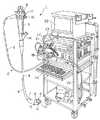
図1ないし図3は本発明の第1の実施の形態に係り、図1は第1の実施の形態を備えた内視鏡システムの全体構成を示し、図2は撮像装置の構成を示し、図3は対物レンズユニット側を回転して偏芯調整を行う説明図を示す。(First embodiment)
1 to 3 relate to a first embodiment of the present invention, FIG. 1 shows an overall configuration of an endoscope system including the first embodiment, FIG. 2 shows a configuration of an imaging apparatus, FIG. 3 is an explanatory diagram for performing eccentricity adjustment by rotating the objective lens unit side.
図1に示すように内視鏡検査を行う内視鏡システム1は、内視鏡2を有し、この内視鏡2は術者が把持して操作を行う操作部3と、この操作部3の前端に形成され、体腔内等に挿入される細長の挿入部4と、操作部3の側部からその基端が延出されたユニバーサルコード5とより構成される。 As shown in FIG. 1, an endoscope system 1 for performing an endoscopic examination includes an endoscope 2, and the endoscope 2 is held by an operator and operated, and the
また、挿入部4は、その先端に設けられた硬質の先端部6と、この先端部6の後端に設けられた湾曲自在の湾曲部7と、この湾曲部7の後端に設けられた長尺で可撓性を有する可撓管部8とからなり、湾曲部7は操作部3に設けられた湾曲操作レバー9により湾曲操作が可能である。 Further, the
また、挿入部4の先端部6には、光学的観察するための対物レンズ11を取り付けた観察窓と、対物レンズ11の表面に水や空気等の流体を噴きつけるノズル12と、照明光を出射して照明する照明窓13と、処置具挿通孔の先端開口14とが設けられている。 Further, the
ノズル12から気体と液体を選択的に噴出させるため、操作部3には送気送水操作ボタン16と、処置具挿通孔の先端開口14より選択的に体腔内の粘液等を回収するための吸引操作ボタン17が配設されている。処置具挿通孔は挿入部4内に配設された図示しないチューブ等によって形成され、操作部3の前端付近に設けた処置具挿入口18と連通している。 In order to selectively eject gas and liquid from the
上記ユニバーサルコード5の末端にはコネクタ19が設けられ、このコネクタ19は内視鏡2の周辺装置としての光源装置21に接続される。このコネクタ19の先端から突出する流体管路の接続端部となる図示しない口金と、照明光の供給端部となる図示しないライトガイド口金とは光源装置21に着脱自在で接続され、また側面に設けた電気接点部には接続ケーブル23の一端が接続される。 A
また、この接続ケーブル23の他端のコネクタは内視鏡2の周辺装置としてのビデオプロセッサ22に電気的に接続され、内視鏡2の先端部6に内蔵した撮像手段を駆動する駆動信号を供給し、この駆動信号の供給により撮像手段から出力される撮像信号(画像信号)に対して信号処理を行い映像信号を生成する。 Further, the connector at the other end of the
そして、この映像信号を内視鏡2の他の周辺装置としてのモニタ25に出力し、モニタ25の表示面に撮像手段で撮像した画像が内視鏡画像として表示される。上記光源装置21、ビデオプロセッサ22、モニタ25等の周辺装置は、患者情報の入力等を行うキーボード24と共に、架台26に配置されている。 Then, this video signal is output to a
光源装置21で発生した照明光は、ユニバーサルコード5から操作部3及び挿入部4内を通した図示しないライトガイドにより伝送され、先端部6の照明窓13から、体腔内に拡開して照射され、患部等の被写体側を照明できるようにしている。 Illumination light generated by the
上記先端部6の観察窓には対物レンズ11を介して体腔内を撮像する図2に示す撮像装置20が配置されている。 An
そして、図2に示すこの撮像装置20から得た体腔内観察像の画像信号は内視鏡2の内部に配設された複数の同軸線44、単純線47より構成される信号ケーブル43を通じて、図1に示すコネクタ19に設けられた電気接点部に伝達され、さらに接続ケーブル23を通じてビデオプロセッサ22に伝達される。 Then, the image signal of the in-vivo observation image obtained from the
次に図2を参照して撮像装置20の構成を説明する。
図2に示すように撮像装置20は、対物レンズユニット31と、この対物レンズユニット31の結像位置に配置される固体撮像装置(固体撮像素子)32を有する固体撮像ユニット33とより構成されている。Next, the configuration of the
As shown in FIG. 2, the
対物レンズユニット31は、対物レンズ11をはじめとする複数の対物レンズ34が円管形状の対物レンズ枠35内に配置されて対物光学系が構成されており、複数の対物レンズ34間には各対物レンズ34を所定位置に配置する為の間隔管36と、フレア等の光学的不具合を防止する為の光学絞り37が複数介在されている。 In the
そして、この対物レンズユニット31の光軸中心“X”は、後述する固体撮像装置枠38と嵌合する対物レンズ枠35の嵌合部中心軸“Y”より、βオフセット(図3(A)参照)された位置に配置されている。なお、図2では、図3(A)における縦方向の成分αオフセットされた状態で示してある。 The optical axis center “X” of the
次に固体撮像ユニット33を説明する。
固体撮像ユニット33を構成する固体撮像装置32は、この固体撮像装置32の受光部を覆う保護ガラス39の前面に紫外線硬化型接着剤等によりカバーガラス40が接着固定された後、フレア絞り41と共に固体撮像装置枠38内に嵌合固定されている。Next, the solid-
The solid-state
この固体撮像装置32の裏面には複数のリードピン42が2列に設けられており、一列のリードピン42には信号ケーブル43を構成する複数の同軸線44が半田等により接続されており、もう一列のリードピン42には複数の電子部品45が予め実装された回路基板46が半田等により接続されている。尚、電子部品45にも単純線47が接続されている。 A plurality of
そして、前記固体撮像装置枠38の後端にはシールド枠48の先端が外嵌して接着剤で固定され、、このシールド枠48により固体撮像装置32及びその裏面側の回路基板46の周囲を覆い、ノイズの侵入等を防止するようにしている。 このシールド枠48の外周側はさらに熱収縮チューブ49により被覆される。尚、シールド枠48内は、固体撮像装置32をはじめとすると電装部を封止する為の例えばエポキシ系の封止樹脂50が充填されている。 The front end of the
また、信号ケーブル43の先端部には、この信号ケーブル43内部に配設される同軸線44及び単純線47が進退移動しないように糸51で縛り固定している。そして、この信号ケーブル43には、この信号ケーブル43を内視鏡2内の他の内蔵物から保護する為の保護チューブ52で被覆され、保護チューブ52の先端部は糸53が巻き締められることにより固定される。 Further, the
本実施の形態の撮像装置20では、以下に説明するようにして、対物光学系の光軸Xと固体撮像装置32の受光部中心Zとの位置ずれ、つまり偏芯を、許容される範囲内に容易に調整できるようにしている。 In the
固体撮像装置32の受光部中心Zは対物レンズユニット31の光軸Xと完全に一致させることは不可能であり、画像不良を発生させない許容される範囲の偏芯量、例えば受光部対角線の長さ(大きさ)が5mm程度の固体撮像装置32であれば20μm以下に抑える必要がある。 The center Z of the light receiving unit of the solid-
しかし、現状の組立精度では双方による偏芯を30μm程度に抑えることが限界である。双方を一致させられない原因は、対物レンズユニット31と固体撮像装置枠38とを嵌合させた時に生じる嵌合誤差:例えば10μmと、固体撮像装置32とカバーガラス40を接合する時に生じる受光部中心Zとカバーガラス中心の偏芯誤差:例えば20μmである。 However, with the current assembly accuracy, it is the limit to suppress the eccentricity due to both to about 30 μm. The reason why both cannot be matched is a fitting error that occurs when the
そこで、本実施の形態では、対物レンズユニット31を構成する対物レンズ11、34の光軸Xを、対物レンズ11、34が配設される対物レンズ枠35と、固体撮像装置32が配設される固体撮像装置枠38との嵌合部中心軸“Y”より所望調整寸法分、例えば、前述した嵌合誤差及び偏芯誤差を調整し得る寸法:β=15μmをオフセットした位置に配置する。 Therefore, in the present embodiment, the optical axis X of the
このことで、組合わされる固体撮像装置枠38内の固体撮像装置32の受光部中心“Z”が嵌合部中心軸“Y”に対して図2或いは図3(A)に示すように偏芯していたとしても、対物レンズユニット31を回転してその際の偏芯量を調整することにより、対物光学系の光軸“X”と固体撮像装置32の受光部中心“Z”とを図3(B)に示すように観察画像上、偏角や片ボケが問題とならない領域B:20μm以下に調整することを可能となるようにしている。 As a result, the light receiving portion center “Z” of the solid
この場合における上記の所望寸法とは、個々の撮像装置を構成する対物レンズ枠35と固体撮像装置枠38との嵌合ガタ及び、固体撮像装置枠38内における固体撮像装置受光部中心Zとの偏芯を調整し得る寸法である。
また、対物レンズユニット31と固体撮像装置枠38との嵌合部断面形状が円形であるため、連続的に細かく回転調整を行うことが可能である。In this case, the above desired dimensions are the looseness between the
Further, since the cross-sectional shape of the fitting portion between the
次に図3を参照して、偏芯量を調整する作用を説明する。なお図3(A)は固体撮像装置枠38との嵌合部の中心軸Y、対物光学系の光軸X、固体撮像装置32の受光部32aの中心Z等の関係の概略図を示し、図3(B)はモニタ25の画面上での偏芯調整の様子を示す。 Next, the effect | action which adjusts the amount of eccentricity is demonstrated with reference to FIG. 3A is a schematic diagram showing the relationship between the center axis Y of the fitting portion with the solid-state
なお、図3(A)は上述のような概略図を示すが、その主要な特徴としては、固体撮像装置枠38の中心軸“Y”に対して、その嵌合部に嵌合する(その外径の中心軸に対して偏芯した内径となる)対物レンズ枠35に取り付けられた対物光学系の光軸“X”が所望調整寸法分、例えば、βだけオフセットしている関係となっており、この関係のために図3(B)のようにして、対物レンズ枠35側を回転することにより、固体撮像装置32の受光部32aの中心Zから許容される距離内に光軸Xの位置を調整可能にしている。 FIG. 3A shows a schematic diagram as described above, and the main feature thereof is that it is fitted to the fitting portion with respect to the central axis “Y” of the solid-state imaging device frame 38 (that The optical axis “X” of the objective optical system attached to the
図3(A)に示すように、その中心軸がYとなる固体撮像装置枠38の(内周面の)嵌合部には、対物レンズユニット31の例えば2点鎖線でその内周面35aを示す対物レンズ枠35の外周面35bが嵌合する。 As shown in FIG. 3A, the inner peripheral surface 35a of the
この対物レンズ枠35はその外周面に対してその内周面が(或いはその逆で内周面に対して外周面が)偏芯するようにして形成され、従って対物レンズ枠35の内周面に取り付けられた対物レンズ11,34の光軸Xは嵌合部の中心軸Yから例えば距離βだけオフセットした状態で偏芯している。
また、2点鎖線で示す固体撮像装置32の受光部32aはその中心Zが殆どの場合、光軸X或いは中心軸Yから偏芯している。The
Further, the light receiving unit 32a of the solid-
この場合、対物レンズユニット31側、つまり対物レンズ枠35を固体撮像装置枠38側に対して回転することにより、光軸Xの位置は中心軸Yの回りで円cを描くように移動することになる。 In this case, the position of the optical axis X moves around the central axis Y so as to draw a circle c by rotating the
そして、中心軸Yと受光部32a中心Zとを結ぶ線に近い領域に近い円c上の位置は受光部32a中心Zからの偏芯量が小さい状態となる。つまり、対物レンズユニット31側を回転することにより、光軸Xと受光部32a中心Zとの偏芯量を小さな状態に調整することができる。 And the position on the circle | round | yen c near the area | region close | similar to the line | wire which connects the center axis | shaft Y and the light-receiving part 32a center Z will be in the state where the amount of eccentricity from the light-receiving part 32a center Z is small. That is, by rotating the
この調整の様子を図3(B)で説明する。
モニタ25上の観察画面上では、固体撮像装置32の受光部32a中心Zが観察視野範囲の中心となるようにビデオプロセッサ22内にて映像処理される為、図3(B)に示すように対物レンズユニット31と固体撮像装置ユニット33をピント出しした初期時の偏芯位置が観察視野中心“O”(受光部中心Zに該当)に対してXaの場合、対物レンズユニット31を回転させることより、観察上支障のない領域B内に含まれるハッチングで示す領域D内に調整することが出来る。This adjustment will be described with reference to FIG.
On the observation screen on the
よって、対物レンズユニット31をハッチングにて示すこの領域D内にて固定することにより、撮像装置20の偏芯量を観察上支障の無い(或いは偏芯や片ボケが問題とならない)位置に調整固定することができる。
なお、図3(B)のように調整する場合、中心軸Yと観察視野中心“O”を結ぶ線分上の偏芯位置Xbに光軸Xを設定すると最も偏芯量が少ない状態に設定できることになる。つまり、Xbはこの場合の撮像装置において、ベストに調整された場合の偏芯位置を示す。Therefore, by fixing the
3B, when the optical axis X is set to the eccentric position Xb on the line segment connecting the central axis Y and the observation visual field center “O”, the state where the amount of eccentricity is the smallest is set. It will be possible. That is, Xb indicates the eccentric position when adjusted to the best in the imaging apparatus in this case.
以上の構成によれば、現状の加工精度、組立精度にて対物光学系の光軸Xと固体撮像装置32の受光部中心Zとの偏芯を許容される値以下に容易に調整することができるので、コストアップすることなく、偏角や片ボケのない良好な撮像画像(観察画像)を得ることができる撮像装置20を提供することが出来る。 According to the above configuration, the eccentricity between the optical axis X of the objective optical system and the light receiving unit center Z of the solid-
なお、上述の説明では、具体的なオフセットの値として、例えばβ=15μmとした場合を挙げたがこれに限定されるものでなく、受光部中心Zとカバーガラス中心の偏芯誤差程度の値としても良い。 In the above description, the specific offset value is, for example, β = 15 μm. However, the present invention is not limited to this, and the value is about the eccentric error between the light receiving portion center Z and the cover glass center. It is also good.
ところで、図4(A)、図4(B)に示す対物レンズユニット60は、(第1)対物レンズ61の外形中心が、その内面(裏面)側のR面62中心と一致するように芯取り形成されると共に、表裏面が側面に対して垂直に形成された対物レンズ61が、対物レンズ枠63の先端部内径に形成されたテーパ部64に当接した位置にて対物レンズ平行出し治具65を用いて接着固定されている。 By the way, the
これにより、対物レンズ61が傾くことなく対物レンズユニット60を形成することが出来るので、偏角・片ボケのない対物レンズユニットを提供することができる。 As a result, the
撮像装置を構成する対物レンズユニットと固体撮像装置ユニットをピント出し調整する為には、双方を保持固定し、双方をピントの合う所望位置にて固定した状態にて接着固定する必要があるが、撮像装置が小型化されるに伴い、対物レンズユニットを構成する対物レンズ枠の肉厚は薄くなる。この為、対物レンズユニットを強く保持してしまうと、対物レンズ粋が変形を起こして、対物レンズ枠と対物レンズの接着面が剥離したり、対物レンズが破損する不具合が生じてしまう。 In order to focus and adjust the objective lens unit and the solid-state imaging device unit constituting the imaging device, it is necessary to hold and fix both, and to fix both in a desired position where both are in focus, As the imaging device is downsized, the thickness of the objective lens frame constituting the objective lens unit is reduced. For this reason, if the objective lens unit is strongly held, the objective lens is deformed, and the adhesion surface between the objective lens frame and the objective lens is peeled off or the objective lens is damaged.
そこで、図5に示すように、対物レンズ枠66の材質を磁性体を含む材料で構成すると共に、対物レンズユニット67を保持するホールド治具68に磁石を用いることで、対物レンズユニット67にメカ的ストレスを加えることなく保持することが可能となる。
尚、対物レンズ枠66は真鍮にて形成し、磁性体を含む素材を用いてメッキしても良い。
以上より、対物レンズユニットを破損することなく撮像装置を組立てることが出来る。Therefore, as shown in FIG. 5, the
The
As described above, the imaging apparatus can be assembled without damaging the objective lens unit.
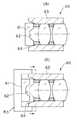
この場合、図6に示すような対物レンズユニット73にしても良い。
つまり、対物レンズ枠69の外形をホールド治具70に形成されたV溝71に当接するようにDカット面72を形成することにより、接着剤硬化時に対物レンズユニット73が回転することを防止することが出来るので、ピント出し時に調整した状態を保つことが可能となり画像不良の発生を防止することが出来る。In this case, an
That is, the
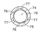
また、対物レンズ枠74内径を図7に示すように対物レンズ75に対してクリアランスが異なる部位76,77を形成し、ピント出し時にはクリアランスが小さい部位76を保持することにより、対物レンズ枠74の変形を防止することが出来るので対物レンズ枠74と対物レンズ75の接着面の剥離を防止することが出来る。 Further, as shown in FIG. 7, the inner diameter of the
なお、図2及び図3を参照しての説明では、固体撮像装置枠38の前端側に対物レンズ枠35が内嵌する例で、説明したが、この関係が逆のものでも適用することができる。 In the description with reference to FIGS. 2 and 3, the example in which the
また、対物光学系の光軸Xを嵌合部中心Yから偏芯させるようにオフセットを与える場合、対物レンズ枠35の内周面等を偏芯させて形成することで所望とする値のオフセットを与えると説明したが、その一部或いは大部分を固体撮像装置枠38側で発生させるようにした場合も本発明に属する。 In addition, when an offset is given so that the optical axis X of the objective optical system is decentered from the fitting portion center Y, an offset of a desired value is formed by decentering the inner peripheral surface of the
1…内視鏡システム
2…内視鏡
3…操作部
4…挿入部
6…先端部
11、34…対物レンズ
20…撮像装置
31…対物レンズユニット
32…固体撮像装置(素子)
32a…受光部
33…固体撮像ユニット
35…対物レンズ枠
37…光学絞り
38…固体撮像装置枠
39…保護ガラス
40…カバーガラス
β…オフセット
X…光軸
Y…嵌合部中心軸
Z…受光部中心
B…偏角や片ボケが問題とならない領域
D…観察上支障のない領域
Xb…ベストに調整された場合の偏芯位置、DESCRIPTION OF SYMBOLS 1 ... Endoscope system 2 ...
32a ...
Claims (3)
Translated fromJapanese前記対物レンズ枠の外周面と嵌合する内周面を有すると共に、前記対物レンズユニットの結像位置においてカバーガラスと一体的に形成された固体撮像装置が配置される固体撮像装置枠とより構成される撮像装置において、
前記対物レンズ枠の外周円筒の中心軸と前記固体撮像装置枠の内周円筒の中心軸とを一致させた状態で、前記対物レンズ枠の外周面と前記固体撮像装置枠の内周面とを当該一致された中心軸周りに回動自在に嵌合し、
前記対物レンズ枠の内周面に配設された前記対物レンズの光軸を、前記対物レンズ枠の外周円筒の中心軸に対して偏心した位置であって、前記対物レンズ枠を前記固体撮像装置枠内に嵌合するよう配設させ、当該対物レンズ枠を当該対物レンズ枠の外周円筒の中心軸周りに回動させた際、当該対物レンズ枠の外周面と前記固体撮像装置枠の内周面との間において嵌合誤差による生じる隙間、または、前記カバーガラスの中心軸と前記固体撮像装置における受光部中心軸との偏心誤差に起因する当該対物レンズの光軸と前記受光部中心軸との偏心を減じることを可能とする位置に配置したことを特徴とする撮像装置。An objective lens unit in which the objective lensis disposed onthe inner peripheral surface of the objective lens frame;
A solid-state imaging device frame having an inner peripheral surface that fits with the outer peripheral surface of the objective lens frame, and in which a solid-state imaging device formed integrally with a cover glass is disposed at the imaging position of the objective lens unit In the imaging device to be
Withthe central axis of the outer peripheral cylinder of the objective lens frame andthe central axis of theinner peripheral cylinder of the solid-state imaging device frame aligned, the outer peripheral surface of the objective lens frame and the inner peripheral surface of the solid-state imaging device frame are Fits aroundthe center axis that ismatched , so that it can rotate freely.
The position of the optical axis of the objective lensdisposed on the inner peripheral surface of the objective lens frame is decentered with respect tothe central axis of theouter peripheral cylinder of the objective lens frame,and the objective lens frameis the solid-state imaging device. When theobjective lens frame is rotated aroundthe central axis of the outer peripheral cylinder of the objective lens frame, the outer peripheral surface of the objective lens frame andthe inner periphery of the solid-state imaging device frame An optical axis of the objective lens and the center axis of the light receiving unitdue to a gap caused by a fitting error between thesurface and the center axis of the cover glass and an eccentric error between the center axis of the light receiving unit in the solid-state imaging device An image pickup apparatus arranged at a position where it is possible to reduce the eccentricity of the image pickup apparatus.
前記対物レンズ枠の外周面と嵌合する内周面を有すると共に、前記対物レンズユニットの結像位置においてカバーガラスと一体的に形成された固体撮像装置が配置される固体撮像装置枠とより構成される撮像装置において、 A solid-state imaging device frame having an inner peripheral surface that fits with the outer peripheral surface of the objective lens frame, and in which a solid-state imaging device formed integrally with a cover glass is disposed at the imaging position of the objective lens unit In the imaging device to be
前記対物レンズ枠の外周円筒の中心軸と前記固体撮像装置枠の内周円筒の中心軸とを一致させた状態で、前記対物レンズ枠を前記固体撮像装置枠内に嵌合するよう配設した後、前記対物レンズ枠の内周面に配設された前記対物レンズの光軸が前記対物レンズ枠の外周円筒の中心軸に対して偏心した位置に配置された前記対物レンズ枠と前記固体撮像装置枠とを、当該対物レンズ枠の外周面と前記固体撮像装置枠の内周面との間において嵌合誤差による生じる隙間、または、前記カバーガラスの中心軸と前記固体撮像装置における受光部中心軸との偏心誤差に起因する当該対物レンズの光軸と前記受光部中心軸との偏心を減じるよう、前記対物レンズ枠の外周円筒の中心軸周りに回動させた後、該対物レンズ枠と該固体撮像装置枠とを固定することを特徴とする撮像装置の組立方法。 The objective lens frame is disposed so as to fit into the solid-state imaging device frame in a state where the central axis of the outer peripheral cylinder of the objective lens frame is aligned with the central axis of the inner cylindrical shape of the solid-state imaging device frame. Thereafter, the objective lens frame disposed on the inner peripheral surface of the objective lens frame and the solid-state imaging with the objective lens frame disposed at a position where the optical axis of the objective lens is decentered with respect to the central axis of the outer peripheral cylinder of the objective lens frame. A device frame, a gap caused by a fitting error between the outer peripheral surface of the objective lens frame and the inner peripheral surface of the solid-state imaging device frame, or the center axis of the cover glass and the center of the light receiving unit in the solid-state imaging device The objective lens frame, after being rotated around the central axis of the outer peripheral cylinder of the objective lens frame so as to reduce the eccentricity between the optical axis of the objective lens and the center axis of the light receiving unit due to an eccentric error with respect to the axis; Fixing the solid-state imaging device frame Assembling method of an imaging apparatus according to claim and.
Priority Applications (1)
| Application Number | Priority Date | Filing Date | Title |
|---|---|---|---|
| JP2008092647AJP5242221B2 (en) | 2008-03-31 | 2008-03-31 | Imaging apparatus, electronic endoscope, and assembling method of imaging apparatus |
Applications Claiming Priority (1)
| Application Number | Priority Date | Filing Date | Title |
|---|---|---|---|
| JP2008092647AJP5242221B2 (en) | 2008-03-31 | 2008-03-31 | Imaging apparatus, electronic endoscope, and assembling method of imaging apparatus |
Related Parent Applications (1)
| Application Number | Title | Priority Date | Filing Date |
|---|---|---|---|
| JP2002271917ADivisionJP2004105450A (en) | 2002-09-18 | 2002-09-18 | Imaging device |
Publications (2)
| Publication Number | Publication Date |
|---|---|
| JP2008257243A JP2008257243A (en) | 2008-10-23 |
| JP5242221B2true JP5242221B2 (en) | 2013-07-24 |
Family
ID=39980803
Family Applications (1)
| Application Number | Title | Priority Date | Filing Date |
|---|---|---|---|
| JP2008092647AExpired - LifetimeJP5242221B2 (en) | 2008-03-31 | 2008-03-31 | Imaging apparatus, electronic endoscope, and assembling method of imaging apparatus |
Country Status (1)
| Country | Link |
|---|---|
| JP (1) | JP5242221B2 (en) |
Families Citing this family (1)
| Publication number | Priority date | Publication date | Assignee | Title |
|---|---|---|---|---|
| JP5866321B2 (en) | 2013-09-02 | 2016-02-17 | 富士フイルム株式会社 | OPTICAL UNIT, ENDOSCOPE DEVICE, AND OPTICAL UNIT MANUFACTURING METHOD |
Family Cites Families (6)
| Publication number | Priority date | Publication date | Assignee | Title |
|---|---|---|---|---|
| JPS57129407A (en)* | 1981-02-03 | 1982-08-11 | Olympus Optical Co Ltd | Hard endoscope |
| JPH0644105B2 (en)* | 1985-01-14 | 1994-06-08 | オリンパス光学工業株式会社 | Endoscope |
| JP2632172B2 (en)* | 1988-01-26 | 1997-07-23 | 旭光学工業株式会社 | Centering mechanism for endoscope end |
| JPH0610334Y2 (en)* | 1988-10-19 | 1994-03-16 | 旭光学工業株式会社 | Endoscope using solid-state image sensor |
| JP4119553B2 (en)* | 1999-01-11 | 2008-07-16 | オリンパス株式会社 | Endoscope |
| JP3520025B2 (en)* | 2000-03-31 | 2004-04-19 | 三洋電機株式会社 | Door monitor |
- 2008
- 2008-03-31JPJP2008092647Apatent/JP5242221B2/ennot_activeExpired - Lifetime
Also Published As
| Publication number | Publication date |
|---|---|
| JP2008257243A (en) | 2008-10-23 |
Similar Documents
| Publication | Publication Date | Title |
|---|---|---|
| JP5054230B2 (en) | Imaging unit | |
| JP5192559B2 (en) | Endoscope | |
| WO2006004123A1 (en) | Electronic endoscope | |
| CN106473692A (en) | endoscope | |
| CN1980597A (en) | Electronic endoscope | |
| JPH11313795A (en) | Endoscope | |
| JP4772826B2 (en) | Imaging device | |
| US20090237497A1 (en) | Endoscope camera head and method for manufacturing the same | |
| JP2000232957A (en) | Endoscopic device | |
| JP5389376B2 (en) | Endoscope imaging unit | |
| JP4262467B2 (en) | Endoscope | |
| JP5175639B2 (en) | Endoscope and its assembly method | |
| JP7176858B2 (en) | Imaging unit and oblique or side-viewing endoscope | |
| JP2012089288A (en) | Cable connection structure, endoscope device, and cable connection method | |
| JP5242221B2 (en) | Imaging apparatus, electronic endoscope, and assembling method of imaging apparatus | |
| JP4938936B2 (en) | Solid-state imaging device | |
| JP2004105450A (en) | Imaging device | |
| JP4647817B2 (en) | Electronic endoscope | |
| JP4709593B2 (en) | Imaging device for electronic endoscope | |
| JP3294397B2 (en) | Electronic endoscope | |
| JP2022179301A (en) | Endoscope imaging device and endoscope | |
| JP2005192642A (en) | Electronic endoscope | |
| JP6744118B2 (en) | Endoscope | |
| JP7592553B2 (en) | Endoscopic imaging device and endoscope | |
| JP2004016337A (en) | Endoscope actuator support structure |
Legal Events
| Date | Code | Title | Description |
|---|---|---|---|
| A131 | Notification of reasons for refusal | Free format text:JAPANESE INTERMEDIATE CODE: A131 Effective date:20110614 | |
| A521 | Written amendment | Free format text:JAPANESE INTERMEDIATE CODE: A523 Effective date:20110815 | |
| A131 | Notification of reasons for refusal | Free format text:JAPANESE INTERMEDIATE CODE: A131 Effective date:20120529 | |
| TRDD | Decision of grant or rejection written | ||
| A01 | Written decision to grant a patent or to grant a registration (utility model) | Free format text:JAPANESE INTERMEDIATE CODE: A01 Effective date:20130319 | |
| A61 | First payment of annual fees (during grant procedure) | Free format text:JAPANESE INTERMEDIATE CODE: A61 Effective date:20130403 | |
| FPAY | Renewal fee payment (event date is renewal date of database) | Free format text:PAYMENT UNTIL: 20160412 Year of fee payment:3 | |
| FPAY | Renewal fee payment (event date is renewal date of database) | Free format text:PAYMENT UNTIL: 20160412 Year of fee payment:3 | |
| S531 | Written request for registration of change of domicile | Free format text:JAPANESE INTERMEDIATE CODE: R313531 | |
| R350 | Written notification of registration of transfer | Free format text:JAPANESE INTERMEDIATE CODE: R350 | |
| R250 | Receipt of annual fees | Free format text:JAPANESE INTERMEDIATE CODE: R250 |