JP5241781B2 - Robot finger assembly - Google Patents
Robot finger assemblyDownload PDFInfo
- Publication number
- JP5241781B2 JP5241781B2JP2010170022AJP2010170022AJP5241781B2JP 5241781 B2JP5241781 B2JP 5241781B2JP 2010170022 AJP2010170022 AJP 2010170022AJP 2010170022 AJP2010170022 AJP 2010170022AJP 5241781 B2JP5241781 B2JP 5241781B2
- Authority
- JP
- Japan
- Prior art keywords
- phalange
- joint
- axis
- finger
- tendons
- Prior art date
- Legal status (The legal status is an assumption and is not a legal conclusion. Google has not performed a legal analysis and makes no representation as to the accuracy of the status listed.)
- Expired - Fee Related
Links
- 210000002435tendonAnatomy0.000claimsdescription51
- 230000035939shockEffects0.000claimsdescription3
- 210000003811fingerAnatomy0.000description52
- 210000000323shoulder jointAnatomy0.000description18
- 210000002310elbow jointAnatomy0.000description16
- 210000001503jointAnatomy0.000description8
- 210000003813thumbAnatomy0.000description7
- 230000005355Hall effectEffects0.000description6
- 230000000712assemblyEffects0.000description6
- 238000000429assemblyMethods0.000description6
- 210000000245forearmAnatomy0.000description3
- 210000004247handAnatomy0.000description3
- 210000000707wristAnatomy0.000description3
- 230000007423decreaseEffects0.000description2
- 239000012636effectorSubstances0.000description2
- 230000007246mechanismEffects0.000description2
- 238000011144upstream manufacturingMethods0.000description2
- 210000003857wrist jointAnatomy0.000description2
- 229910000906BronzeInorganic materials0.000description1
- 229920000508VectranPolymers0.000description1
- 239000004979VectranSubstances0.000description1
- 230000002457bidirectional effectEffects0.000description1
- 239000010974bronzeSubstances0.000description1
- 230000008859changeEffects0.000description1
- KUNSUQLRTQLHQQ-UHFFFAOYSA-Ncopper tinChemical compound[Cu].[Sn]KUNSUQLRTQLHQQ-UHFFFAOYSA-N0.000description1
- 230000001419dependent effectEffects0.000description1
- 239000000463materialSubstances0.000description1
- 230000003278mimic effectEffects0.000description1
- 229920000642polymerPolymers0.000description1
- 230000004044responseEffects0.000description1
Images


Classifications
- B—PERFORMING OPERATIONS; TRANSPORTING
- B25—HAND TOOLS; PORTABLE POWER-DRIVEN TOOLS; MANIPULATORS
- B25J—MANIPULATORS; CHAMBERS PROVIDED WITH MANIPULATION DEVICES
- B25J9/00—Programme-controlled manipulators
- B25J9/10—Programme-controlled manipulators characterised by positioning means for manipulator elements
- B25J9/104—Programme-controlled manipulators characterised by positioning means for manipulator elements with cables, chains or ribbons
- B—PERFORMING OPERATIONS; TRANSPORTING
- B25—HAND TOOLS; PORTABLE POWER-DRIVEN TOOLS; MANIPULATORS
- B25J—MANIPULATORS; CHAMBERS PROVIDED WITH MANIPULATION DEVICES
- B25J15/00—Gripping heads and other end effectors
- B25J15/08—Gripping heads and other end effectors having finger members
- B—PERFORMING OPERATIONS; TRANSPORTING
- B25—HAND TOOLS; PORTABLE POWER-DRIVEN TOOLS; MANIPULATORS
- B25J—MANIPULATORS; CHAMBERS PROVIDED WITH MANIPULATION DEVICES
- B25J15/00—Gripping heads and other end effectors
- B25J15/0009—Gripping heads and other end effectors comprising multi-articulated fingers, e.g. resembling a human hand
Landscapes
- Engineering & Computer Science (AREA)
- Robotics (AREA)
- Mechanical Engineering (AREA)
- Manipulator (AREA)
Description
Translated fromJapanese(連邦政府の支援を受けた研究または開発に関する陳述)
[0001]本発明は、NASA宇宙活動協定(NASA Space Act Agreement)第SAA−AT−07−003号の下において政府支援によりなされた。政府は、本発明において一定の権利を有し得る。(Federal-supported research or development statement)
[0001] This invention was made with government support under NASA Space Act Agreement No. SAA-AT-07-003. The government may have certain rights in the invention.
[0002]本発明は、ロボット手に関し、より詳細には、ロボット指に関する。 [0002] The present invention relates to robot hands, and more particularly to robot fingers.
[0003]典型的なロボットは、関節部またはモータ駆動型ロボット関節を介して相互連結される一連の剛体リンクを使用して、物体を操作することが可能な、自動型デバイスである。典型的なロボットにおける各関節は、自由度(DOF:degree of freedom)とも呼ばれる、独立した制御変数を呈する。エンドエフェクタは、例えば作業工具または物体を把持するなど、手元の作業を実施するために使用される特定のリンクである。したがって、ロボットの正確な動作制御は、タスクレベルの指定により調整され得て、すなわち、物体レベル制御(すなわちロボットの片手または両手の中に保持された物体の挙動を制御する能力)、エンドエフェクタ制御、および関節レベル制御によって、調整され得る。集合的に、種々の制御レベルが協働して、所要のロボット動作性、器用さ、および作業タスク関連機能性を達成する。 [0003] A typical robot is an automated device that can manipulate objects using a series of rigid links that are interconnected via joints or motor-driven robotic joints. Each joint in a typical robot exhibits an independent control variable, also called a degree of freedom (DOF). An end effector is a specific link that is used to perform a task at hand, such as gripping a work tool or object. Thus, the precise motion control of the robot can be adjusted by task level designation, ie, object level control (ie, the ability to control the behavior of an object held in one or both hands of the robot), end effector control , And by joint level control. Collectively, the various control levels work together to achieve the required robot operability, dexterity, and work task related functionality.
[0004]人間型ロボットは、とりわけ、全身、胴部、およびまたは付属物であるか否かに関わらず、ほぼ人間の構造または外観を有するロボットであり、人間型ロボットの構造的複雑さは、実施される作業タスクの性質に大きく左右される。人間型ロボットの使用は、特に人間が使用するように作製されたデバイスまたはシステムと直接的に相互にやり取りすることが必要な場合に、好ましい場合がある。幅広い範囲の作業タスクが人間型ロボットに期待され得ることにより、異なる制御モードが、同時に必要とされる場合がある。例えば、正確な制御が、加えられるトルクまたは力、動作、および種々の把持タイプに対する制御と並び、上述の様々な空間内において与えられなければならない。 [0004] A humanoid robot is a robot that has a generally human structure or appearance, whether or not it is a whole body, a torso, and / or an appendage, and the structural complexity of a humanoid robot is It is highly dependent on the nature of the work task being performed. The use of a humanoid robot may be preferred, especially when it is necessary to interact directly with a device or system that is made for human use. Due to the wide range of work tasks that can be expected of a humanoid robot, different control modes may be required simultaneously. For example, precise control must be provided in the various spaces described above, along with the applied torque or force, motion, and control for the various gripping types.
[0005]本開示の第1の態様によれば、ロボット手アセンブリは、ベース構造体と、第1、第2、および第3の指骨を有する指と、第1の指骨が第1の軸を中心としてベース構造体に対して選択的に回転可能となるように、ベース構造体に第1の指骨を作動的に連結する第1の関節と、第2の指骨が第2の軸を中心として第1の指骨に対して選択的に回転可能となるように、第1の指骨に第2の指骨を作動的に連結する第2の関節と、第3の指骨が第3の軸を中心として第2の指骨に対して選択的に回転可能となるように、第2の指骨に第3の指骨を作動的に連結する第3の関節とを備える。 [0005] According to a first aspect of the present disclosure, a robotic hand assembly includes a base structure, a finger having first, second, and third phalanges, and the first phalange has a first axis. A first joint for operatively connecting the first phalange to the base structure and a second phalange centered about the second axis so as to be selectively rotatable relative to the base structure as a center; A second joint operatively connecting the second phalange to the first phalange so as to be selectively rotatable with respect to the first phalange, and the third phalange about the third axis A third joint for operatively connecting the third phalange to the second phalange so as to be selectively rotatable with respect to the second phalange.
[0006]第3の関節は、第2の指骨に対する第3の指骨の位置が第1の指骨に対する第2の指骨に位置によって決定されるように、第2の関節に運動学的にリンクされる。この第2および第3の関節間の運動学的リンクは、人間の指の複数の自由度の中の1自由度と置き換わると共に、人間の指の動作を細密に模倣する。 [0006] The third joint is kinematically linked to the second joint such that the position of the third phalange relative to the second phalange is determined by position relative to the second phalange relative to the first phalange. The This kinematic link between the second and third joints replaces one of the degrees of freedom of the human finger and closely mimics the movement of the human finger.
[0007]本開示の第2の態様によれば、ロボット手アセンブリは、第1の指骨および第2の指骨を有するロボット指と、第1の指骨が第2の指骨に対して選択的に回転可能となるように、第1の指骨と第2の指骨とを相互連結する関節とを備える。磁石が、第1の指骨
に対して取り付けられ、第1の中心点により特徴付けられる第1の円セグメントを形成する第1の部分を有し、第2の中心点により特徴付けられる第2の円セグメントを形成する第2の部分を有する。ホール効果センサが、第1の指骨に対して第2の指骨と共に回転するように、第2の指骨に対して取り付けられる。この磁石の形状により、ホール効果センサの線形出力が得られ、これにより、ロボット手のための制御システムに対して正確に位置データが提供される。
本開示の一態様によれば、第1の指骨および第2の指骨を備えるロボット指と、前記第1の指骨が前記第2の指骨に対して選択的に回転可能となるように、前記第1の指骨と前記第2の指骨とを相互連結する関節と、前記第1の指骨に対して取り付けられ、第1の中心点により特徴付けられる第1の円セグメントを形成する第1の部分を有し、第2の中心点により特徴付けられる第2の円セグメントを形成する第2の部分を有する磁石と、前記第1の指骨に対して前記第2の指骨と共に回転するように、前記第2の指骨に対して取り付けられたホール効果センサと、を備える、ロボット手アセンブリが提供される。
本開示の一態様によれば、前記ホール効果センサおよび前記磁石は、前記ホール効果センサが前記第2の指骨の回転範囲にわたって前記第1の部分から一定の距離を維持するように、配設される。
本開示の一態様によれば、前記磁石は、前記第1および第2の中心点の周囲を囲む。
本開示の一態様によれば、前記第1の円セグメントは、第1および第2の交点にて前記第2の円セグメントと交差し、前記磁石の北磁極が、前記第1の交点に位置し、前記磁石の南磁極が、前記第2の交点に位置する。
本開示の一態様によれば、前記第1の円セグメントの半径が、前記第2の円セグメントの半径と等しい。[0007] According to a second aspect of the present disclosure, a robot hand assembly includes a robot finger having a first phalange and a second phalange, and the first phalange selectively rotates relative to a second phalange. A joint for interconnecting the first phalange and the second phalange is provided to enable. A magnet is attached to the first phalange and has a first portion that forms a first circular segment that is characterized by a first center point, and a second feature that is characterized by a second center point. Having a second portion forming a circular segment. A Hall effect sensor is attached to the second phalange such that it rotates with the second phalange relative to the first phalange. This magnet shape provides a linear output of the Hall effect sensor, which provides accurate position data to the control system for the robot hand.
According to an aspect of the present disclosure, the robot finger including the first phalange and the second phalange, and the first phalange can be selectively rotated with respect to the second phalange. A joint that interconnects one phalange and the second phalange, and a first portion that is attached to the first phalange and that forms a first circular segment characterized by a first center point; A magnet having a second portion forming a second circular segment characterized by a second center point, and rotating with the second phalange with respect to the first phalange. A robotic hand assembly is provided comprising a Hall effect sensor attached to two phalanges.
According to one aspect of the present disclosure, the Hall effect sensor and the magnet are disposed such that the Hall effect sensor maintains a constant distance from the first portion over a rotation range of the second phalange. The
According to one aspect of the present disclosure, the magnet surrounds the first and second center points.
According to one aspect of the present disclosure, the first circular segment intersects the second circular segment at a first and second intersection, and the north pole of the magnet is located at the first intersection. The south pole of the magnet is located at the second intersection.
According to one aspect of the present disclosure, the radius of the first circle segment is equal to the radius of the second circle segment.
[0008]添付の図面と関連させて理解することにより、本発明を実施するための最良の形態の以下の詳細な説明から、本発明の上述の特徴および利点ならびに他の特徴および利点が、容易に明らかになる。 [0008] The foregoing and other features and advantages of the present invention will be readily understood from the following detailed description of the best mode for carrying out the invention, when understood in conjunction with the accompanying drawings. Becomes clear.
[0028]同様の参照番号が複数の図面にわたって同一または類似の構成要素を指す図面を参照すると、図1は、多自由度(DOF)により1つまたは複数のタスクを実施するように適合化された器用な人間型ロボット10を示す。 [0028] Referring to the drawings, in which like reference numerals refer to the same or similar components throughout the drawings, FIG. 1 is adapted to perform one or more tasks with multiple degrees of freedom (DOF). A dexterous
[0029]この人間型ロボット10は、頭部12、胴部14、腰部15、腕16、手18、指19Aから19D、および親指21を備えてよく、それらの中またはそれらの間に、多様な関節が配設される。さらに、ロボット10は、脚部、トレッド、または、ロボットの特定の用途もしくは意図される用途に応じた別の可動式または固定式ベースなどの、タスクに適した固定具またはベース(図示せず)を備えてもよい。例えば胴部14の背の上に担持または着用される再充電式電池パックまたは別の適切なエネルギー供給部などの電源部13が、ロボット10に一体的に設置されてよい。 [0029] The
[0030]一実施形態によれば、ロボット10は、肩関節アセンブリ(矢印A)、肘関節アセンブリ(矢印B)、手首関節アセンブリ(矢印C)、首関節アセンブリ(矢印D)、および腰部関節アセンブリ(矢印E)、さらには各ロボット指19Aから19Dおよび親指21の指骨間に位置する様々な指関節アセンブリおよび親指関節アセンブリ(矢印F)などの(それらに限定されない)、複数の独立的に可動なロボット関節および相互依存的に可動なロボット関節によって、構成される。 [0030] According to one embodiment, the
[0031]アーム16は、上腕22および下腕(または前腕)24に区分される。上腕22は、肩関節アセンブリ(矢印A)から肘関節アセンブリ(矢印B)まで延在する。肘関節(矢印B)から延在するのは、下腕24、手18、指19、および親指21である。単純化のため、本明細書において説明されるように、上方は頭部12の方向であり、下方は腰部15の方向である。ロボット10は、人間の形を模するように意図されるため、このロボットは、胴部および頭部を二分する垂直平面に関して実質的に対称的であり、左側および右側の両側に同一の対称的な構造を基本的に備えることが、当業者には理解されよう。 [0031] The
[0032]図2を参照すると、上腕22が図示されている。複数の腕16に対して一方の上腕22のみが図示されているが、左腕および右腕16は共に、以下に説明するように同一の態様で作動する。上腕22は、第1のDOFを実現する第1の肩関節S1、第2のDOFを実現する第2の肩関節S2、および第3の自由度を実現する第3の肩関節S3を含む、肩関節アセンブリ(矢印A)を有する。第1から第3の肩関節S1、S2、S3は共に、人間の肩が行なうことが可能な動作に相当する動作を行なう。具体的には、第1の肩軸SA1を中心とした第1の肩関節S1の回転により、第2の肩関節S2に関する第2の肩軸SA2が、所望の位置へと移動する。第1の肩関節S1の位置に基づき、次いで、第2の肩軸SA2を中心とする第2の肩関節S2の回転により、腕16が、胴部14に対して上下に、または胴部14に対して前後に移動する。第3の肩関節S3は、第3の肩軸SA3を中心として上腕22を回転させる。第3の肩関節S3の回転により、上腕22は、軸方向に回転し、すなわち、第3の肩関節S3の回転により、肘関節アセンブリ(矢印B)が回転されて、上方または下方に向けられる。したがって、第1の肩関節S1、第2の肩関節S2、および第3の肩関節S3が共に、肩関節アセンブリ(矢印A)の動作を形成する。 [0032] Referring to FIG. 2, the
[0033]さらに、上腕22は、第1の肘関節L1および第2の肘関節L2を含む肘関節アセンブリ(矢印B)を備える。第1の肘関節L1および第2の肘関節L2はそれぞれ、1自由度を実現する。第1の肘関節L1および第2の肘関節L2が共に、人間の肘が行なうことが可能な動作に相当する動作を行なう。第1の肘軸B1を中心とする第1の肘関節L1の回転により、肘関節アセンブリ(矢印B)の下方の上腕22が、屈曲する、および直線状になる。さらに、第2の肘軸B2を中心とする第2の肘関節L2の回転により、肘関節アセンブリ(矢印B)の下方の上腕22が、軸方向に回転し、すなわち、第2の肘軸B2を中心とする第2の肘関節L2の回転により、下腕24および手18(図1)が回転されて、手のひらが上方または下方に向けられる。 [0033] The
[0034]図3は、手首関節アセンブリ(矢印C)、手18、指19Aから19D、および親指21を含む、下腕24を図示する。下腕24は、複数の指(および親指)アクチュエータ26と、複数の手首アクチュエータ28とを備える。さらに、指アクチュエータ26および手首アクチュエータ28のための複数の制御部30が、下腕24上に支持される。下腕24は、下腕24を上腕22に連結するために使用されるロードセル32に装着される。手18は、手18の手のひら36を画成するベース構造体34を備える。指19Aから19Dおよび親指21は、ベース構造体34に可動式に設置され、図1において20で示されるものなどの物体を把持するために手のひら36の方向に選択的にカールする。 FIG. 3 illustrates a
[0035]図示される実施形態においては、手18は、サイズにおいて、人間の男性の手の60から85パーセンタイルに相当する。より具体的には、図示される実施形態においては、手18の長さは、20.1cm(7.9インチ)(人間の80パーセンタイル)であり、手18の広さまたは幅は、9.14cm(3.6インチ)(人間の60パーセンタイル)であり、手の周囲(ベース構造体の周り)は、22.4cm(8.8インチ)(人間の85パーセンタイル)である。 [0035] In the illustrated embodiment, the
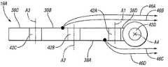
[0036]図4から図7を参照すると、指19Aは、位置および機能において、人間の人差し指に相当する。指19Aは、手18のベース構造体34に作動的に連結されるベース部材37を含む。さらに、指19Aは、複数の剛体リンクすなわち指骨38Aから38Dと、4つの関節42Aから42Dを含む。関節42Aは、指骨38Aが軸A1を中心として構造体34に対して選択的に回転可能となるように、ベース構造体34に対して近位指骨38Aを作動的に連結させる。関節42Bは、指骨38Bが軸A2を中心として指骨38Aに対して選択的に回転可能となるように、指骨38Aに対して指骨38Bを回転自在に取り付ける。関節42Cは、指骨38Cが軸A3を中心として指骨38Bに対して選択的に回転可能となるように、指骨38Bに対して指骨38Cを回転自在に取り付ける。軸A1、A2、およびA3は、互いに対して平行である。 [0036] Referring to FIGS. 4-7, the
[0037]図示される実施形態においては、近位指骨38Aは、指骨38D、関節42D、およびベース部材37によって、ベース構造体34に作動的に連結される。より具体的には、関節42Aは、指骨38Dに対して指骨38Aを回転自在に取り付け、関節42Dは、指骨38D、およびそれに伴って指骨38Aから38Cが、軸A4を中心としてベース部材37およびベース構造体34に対して選択的に回転可能となるように、ベース部材37に対して指骨38Dを回転自在に取り付ける。軸A4は、軸A1、A2、およびA3に対して垂直である。したがって、関節42Dにより、指19Aの左右への回転が可能となる。 [0037] In the illustrated embodiment,
[0038]図7から図8を参照すると、指19Aは、リンケージ43を含む。リンケージ43の一方の端部は、リンケージ43が、軸A1、A2、およびA3に対して平行である軸を中心として指骨38Aに対して選択的に回転可能となるように、関節44Aによって指骨38Aに回転自在に連結される。リンケージ43の他方の端部は、リンケージ43が、軸A1、A2、およびA3に対して平行である軸を中心として指骨38Cに対して選択的に回転可能となるように、関節44Bによって指骨38Cに回転自在に連結される。したがって、指骨38Aから38Cおよびリンケージ43は、協働して4棒リンク機構を形成する。 [0038] Referring to FIGS. 7-8, the
[0039]同様の参照番号が図1から図8による同様の構成要素を指す図9を参照すると、関節42Aから42Dを中心とする指骨38Aから38Dの動きは、ロボットの腱46Aから46D、すなわちケーブルなどの可撓性部材によって、実現される。腱46Aから46Dはそれぞれ、前腕(図3において24で示される)内において、各アクチュエータ(図3において26で示される)に作動的に連結される。例示の一実施形態においては、アクチュエータ26は、電気モータであり、この電気モータは、モータの回転運動を腱46Aから46Dを駆動させる直線運動へと変換させるように構成された駆動機構によって、腱46Aから46Dに作動的に連結される。前腕24および/または手首の中にアクチュエータおよび駆動機構を配置することは、手18のコンパクト性に寄与する。 [0039] Referring to FIG. 9, in which like reference numerals refer to like components according to FIGS. 1-8, the movement of the
[0040]関節42Aから42Dおよび軸A1からA4に対して腱46Aから46Dをルーティングすることによって、4つの腱46Aから46Dのみを使用することによる3自由度にわたる指19Aの完全な制御が可能となる。2つの対向する腱46A、46Bは、中間ピッチ関節42Bを制御し、2つの対向する腱46C、46Dは、近位ピッチ関節42Aを制御する。腱46Bの一方の端部は、指骨38Bが、腱46Bにおける張力によって第1の方向48に軸A2を中心として指骨38Aに対して回転されるように、関節42Bおよび軸A2の一方の側において指骨38Bに対して作動的に連結される。腱46Aの一方の端部は、指骨38Bが、腱46Aにおける張力によって第1の方向48とは逆の第2の方向52に軸A2を中心として指骨38Aに対して回転されるように、関節42Bおよび軸A2の、腱46Bとは逆の側において、指骨38Bに対して作動的に連結される。 [0040]
[0041]腱46Dの一方の端部は、指骨38Aが、腱46Dにおける張力によって第1の方向48に軸A1を中心として指骨38Dに対して回転されるように、関節42Aおよび軸A1の一方の側において指骨38Aに対して作動的に連結される。腱46Cの一方の端部は、指骨38Aが、腱46Cにおける張力によって第2の方向52に軸A1を中心として指骨38Dに対して回転されるように、関節42Aおよび軸A1の、腱46Dとは逆の側において、指骨38Aに対して作動的に連結される。第1の方向48への指骨の回転により、指骨は、図5から図6に図示されるように、手のひら36の方向に回転され、したがって、第1の方向48への指骨の回転により、手18は物体を把持することが可能となる。第2の方向52への指骨の回転により、指骨は、手のひら36から離れる方向へ回転され、したがって、指19は、物体に対する把持を緩める。 [0041] One end of the tendon 46D is one of the joint 42A and the axis A1 such that the
[0042]再び図7から図8を参照すると、関節42Cは、リンケージ43によって関節42Bに運動学的にリンクされ、したがって、関節42Cの角度位置は、関節42Bの角度位置に左右される。したがって、指骨38Bに対する指骨38Cの回転位置は、指骨38Aに対する指骨38Bの回転位置に左右される。より具体的には、指骨38Cと38Bとの間に形成される角度βは、指骨38Bと38Aとの間に形成される角度αによって決定される。つまり、αが小さくなるのに伴って、βが小さくなる。関節42Cと関節42Bとの回転位置間の1つの例示的な関係が、図10に示される。 [0042] Referring again to FIGS. 7-8, the joint 42C is kinematically linked to the joint 42B by the
[0043]図10を参照すると、関節42Cの角度が、関節42Bの角度の関数として示される。この関数は、指19Aの設計制約条件が許容する限りにおいて線形であることが望ましい場合がある。指骨38Aから38Cおよびリンケージ43を含む4棒リンク機構は、リンケージ43がその端部シャフト間の直線部材であり、把持の際には引張状態におかれるように、設計される。一実施形態におけるリンケージ43は、剛性部材であり、別の実施形態においては、リンケージ43は、把持の際に遠位ピッチ関節42Cのコンプライアント性を実現するように、ばねなどのコンプライアント部材である。 [0043] Referring to FIG. 10, the angle of joint 42C is shown as a function of the angle of joint 42B. It may be desirable for this function to be linear as long as the design constraints of
[0044]したがって、腱46Aおよび46Bは、それらによる関節42Bの制御を介して、関節42Cの位置を制御する。人間の指は、4つの個別に制御可能な自由度を有するものとして、一般的には見なされる。関節42Bおよび42Cを運動学的にリンクすることにより、指19Aは、3つのみの個別に制御可能な自由度により、人間の指によって実現可能な姿勢を効果的に模倣し、これにより、関節42Dを個別に制御するために必要な腱が不要となる。 [0044] Accordingly,
[0045]同様の参照番号が図1から図10による同様の構成要素を指す図11を参照すると、ヨー関節42Dの位置の制御専用の腱が、存在しない。代わりに、腱46Aおよび46Bは、関節42Dおよび軸A4の一方の側にルーティングされ、腱46Cおよび46Dは、関節42Dおよび軸A4の別の側にルーティングされる。これら4つの腱46Aから46Dにおける張力のバランスが、関節42Dの位置を制御するために、およびこれに伴って、ベース構造体34に対する指骨38Aから38Dの角度位置を制御するために、操作される。 [0045] Referring to FIG. 11, where like reference numbers refer to like components according to FIGS. 1-10, there is no tendon dedicated to controlling the position of the yaw joint 42D. Instead,
[0046]図12を参照すると、指19Aは、少なくとも2つのタイプのセンサを含む。より具体的には、指19Aのこれらのセンサには、触覚ロードセル54Aから54Cが含まれ、これらはそれぞれ、各指骨38Aから38Cに取り付けられる。さらに、指19Aは、複数の関節位置センサアセンブリ56Aから56Cを含み、これらはそれぞれ、関節42Aから42Cのそれぞれの絶対角度位置と、連結指骨に対する指骨の相対角度位置とを測定するように構成される。関節位置センサアセンブリ56Aから56Cはそれぞれ、各磁石58Aから58Cと、各ホール効果センサ62Aから62Cとを含む。 [0046] Referring to FIG. 12,
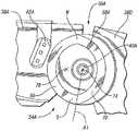
[0047]図13を参照すると、センサアセンブリ56Aが、センサアセンブリ56Bおよび56Cを代表し、したがって、磁石58Aおよびセンサ62Aが、磁石58B、58Cと、センサ62B、62Cとをそれぞれ代表する。磁石58Aは、指骨38Dに対して剛体的に取り付けられ、センサ62Aは、指骨38Aに対して剛体的に取り付けられる。磁石58Aは、2つの部分66、70によって特徴付けされる。部分66は、軸A1上に中心点74を有する円のセグメントである。部分70は、78に中心点を有する円のセグメントである。磁石58Aの北磁極Nは、部分66、70の1つの交点に配設され、磁石58Aの南磁極Sは、部分66、70の他の交点に配設される。図示される実施形態においては、部分66は、部分70と同一の半径を有し、部分66、70の凹部側が、互いに対向する。磁石58Aは、両中心点74、78の周囲を囲む。 [0047] Referring to FIG. 13,
[0048]センサ62Aは、指骨38Aが軸A1を中心として指骨38Dに対して回転する際に、センサ62Aが磁石58Aの部分66から一定の距離を維持するように、指骨38Aの上に位置決めされる。磁石58Aの形状、およびセンサ62Aを配置することにより、指骨38Dに対する指骨38Aの角度位置と、センサ62Aにより読み取られる磁場の変化との間の線形関係が実現される。図示される実施形態においては、センサアセンブリ56Aは、150度の利用可能な角度位置範囲にわたって、ほぼ線形の信号を生成する。 [0048] The
[0049]磁石58Aは、指骨38Dに対して取り付けられ、センサ62Aは、指骨38Aに対して取り付けられ、したがって、センサアセンブリ56Aは、指骨38Dに対する指骨38Aの回転位置を測定する。磁石58Bは、指骨38Bに対して取り付けられ、センサ62Bは、指骨38Aに対して取り付けられ、したがって、センサアセンブリ56Bは、指骨38Aに対する指骨38Bの回転位置を測定する。磁石58Cは、指骨38Cに対して取り付けられ、センサ62Cは、指骨38Bに対して取り付けられ、したがって、センサアセンブリ56Cは、指骨38Bに対する指骨38Cの回転位置を測定する。センサアセンブリ56Aから56Cと実質的に同一のセンサアセンブリ(図示せず)が、指骨38Dが軸A4を中心として回転する際に、ベース部材37に対する指骨38Dの位置を測定する。 [0049] The
[0050]図示される実施形態においては、関節42A(近位ピッチ)の動作範囲は、−10°から95°であり、関節42B(中間ピッチ)の動作範囲は、0°から120°であり、関節42C(遠位ピッチ)の動作範囲は、0°から70°であり、関節42D(ヨー)の動作範囲は、−20°から20°である。 [0050] In the illustrated embodiment, the range of motion of joint 42A (proximal pitch) is -10 ° to 95 °, and the range of motion of joint 42B (intermediate pitch) is 0 ° to 120 °. The motion range of the joint 42C (distal pitch) is 0 ° to 70 °, and the motion range of the joint 42D (yaw) is −20 ° to 20 °.
[0051]図12および図14を参照すると、指19Aは、緩衝取付部82によってベース構造体34に取り付けられる。緩衝取付部82は、キー溝付きシャフト86、保持リング90、およびばね94を含む。円筒状シャフト86は、ベース構造体34によって画成された円筒状空洞部98内に摺動的に係合される。矩形キー102が、構造体34に対するシャフト86の回転を防止するように、空洞部98の矩形部分106内に延在する。保持リング90は、空洞部98よりも大きく、したがって、空洞部98の内部にシャフト86を保持する。ばね94は、シャフト86を外方に付勢し、指19Aに対してかけられ得る衝撃を吸収する。 [0051] Referring to FIGS. 12 and 14, the
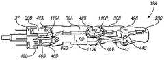
[0052]腱46Aから46Dは、図9および図11においては指骨38Aから38Dの外部に位置するものとして示されるが、これらの腱はそれぞれ、各内部ガイドチャネルを貫通してルーティングされることに留意されたい。図示される実施形態においては、腱46Aから46Dは、編組まれたポリマーである。図15を参照すると、指19Aは、110A、110B、110Cで示されるものなどの挿入体を含み、これらの位置においては、腱46Aから46Dの摺動摩擦が生じる。挿入体110A、110B、110Cは、指骨38Aから38Dの構造材料よりも軟質かつ脆弱であり、選択的に置換可能である。一実施形態においては、腱46Aから46Dは、Vectran(登録商標)を含み、挿入体110A、110B、110Cは、青銅である。 [0052] Although
[0053]図16および図17を参照すると、指19Aは、対向する腱の対ごとに、各二方向性腱ターミネータ114A、114Bを収容するように構成される。より具体的には、腱46Aは、軸A1およびA2の、非手のひら側すなわち甲側に延在し、腱ターミネータ114Aを介して指骨38Bに取り付けられる。腱46Bは、軸A1およびA2の手のひら側に延在し、腱ターミネータ114Aを介して指骨38Bに取り付けられる。同様に、腱46Cは、軸A1の非手のひら側に延在し、腱ターミネータ114Bによって指骨38Aに取り付けられる。腱46Dは、軸A1の手のひら側に延在し、腱ターミネータ114Bによって指骨38Aに取り付けられる。 [0053] Referring to FIGS. 16 and 17, a
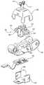
[0054]図18を参照すると、指骨38が、破断斜視図において示される。指骨38は、指骨38Aから38Cを代表し、センサ54は、センサ54Aから54Cを代表する。指骨38は、開口122によって特徴付けられるチャンバ118を画成する。コンパクト電子機器126が、チャンバ118内に収容される。この電子機器126の機能には、センサに対して電力を供給すること、アナログセンサデータを収集すること、アナログ信号をデジタル信号に変換すること、デジタル信号を多重送信すること、および、上流の電子機器にデータを通信することが含まれる。再び図16を参照すると、指19Aは、センサ、コンパクト電子機器、および上流電子機器を接続するために必要な配線を収容するための、指19Aの長さにわたって延在する中央チャネル128を備える。 [0054] Referring to FIG. 18, the
[0055]図18および図19を参照すると、センサ54は、センサカバー130およびセンサアセンブリ134を含む。センサアセンブリ134は、センサカバー130に対してかけられる荷重に応答してセンサ信号を生成し、このセンサ信号を電子機器126に送信する。センサアセンブリ134は、概してC字形状であり、各端部のフランジ138、142により特徴付けられる。各フランジ138、142は、指骨38により形成される各鞍部146、150に当接する。さらに、センサアセンブリ134のフランジ138、142は、各スロット154、158を部分的に画成する。 With reference to FIGS. 18 and 19, the
[0056]C字形状クリップ162は、各端部にフランジ166、170を備える。クリップ162は、チャンバ118およびこのチャンバ118内に収容される電子機器126を封入するために、開口122の両端間にわたって延在する。各フランジ166、170は、センサアセンブリ134にクリップ162を固定するために、および、指骨38に対してセンサアセンブリ134を保持するために、スロット154、158の各一方に係合する。カバー130は、ねじ174によってセンサアセンブリ134に取り付けられる。 [0056] The C-shaped
[0057]図16を再び参照すると、指19Aは、環境から保護するためのグローブまたは皮膚様カバー(図示せず)に対応するように、および、ある特定のタスクに適した触覚センサに対して把持表面を与えるように、設計される。指19Aは、指に対してグローブまたは皮膚様カバーを固定するように設計された複数のねじ山付き装着ホール178を備え、重要な位置におけるすべりを防ぐ。 [0057] Referring again to FIG. 16, the
[0058]本発明を実施するための最良の実施形態を詳細に説明したが、この発明が関係する技術の当業者には、添付の特許請求の範囲内において本発明を実施するための様々な代替の設計および実施形態が認識されよう。 [0058] While the best mode for carrying out the invention has been described in detail, those skilled in the art to which this invention pertains will have various embodiments for carrying out the invention within the scope of the appended claims. Alternative designs and embodiments will be recognized.
Claims (5)
Translated fromJapanese第1、第2、および第3の指骨を有する指と、
前記第1の指骨が第1の軸を中心として前記ベース構造体に対して選択的に回転可能となるように、前記ベース構造体に前記第1の指骨を作動的に連結する第1の関節と、
前記第2の指骨が第2の軸を中心として前記第1の指骨に対して選択的に回転可能となるように、前記第1の指骨に前記第2の指骨を作動的に連結する第2の関節と、
前記第3の指骨が第3の軸を中心として前記第2の指骨に対して選択的に回転可能となるように、前記第2の指骨に前記第3の指骨を作動的に連結する第3の関節と、
第1の腱における張力により前記第2の軸を中心として第1の方向に前記第2の指骨が回転されるように、前記第2の指骨に対して作動的に連結される前記第1の腱と、
第2の腱における張力により前記第2の軸を中心として第2の方向に前記第2の指骨が回転されるように、前記第2の指骨に対して作動的に連結される前記第2の腱と、
第3の腱における張力により前記第1の軸を中心として前記第1の方向に前記第1の指骨が回転されるように、前記第1の指骨に対して作動的に連結される前記第3の腱と、
第4の腱における張力により前記第1の軸を中心として前記第2の方向に前記第1の指骨が回転されるように、前記第1の指骨に対して作動的に連結される前記第4の腱と、
前記第1の関節により前記第1の指骨に回転自在に連結される第4の指骨と、
前記第4の指骨が第4の軸を中心として前記ベース構造体に対して選択的に回転可能となるように、前記ベース構造体に前記第4の指骨を作動的に連結する第4の関節と、
を備え、
前記第3の関節は、前記第2の指骨に対する前記第3の指骨の位置が、前記第1の指骨に対する前記第2の指骨の位置により決定されるように、前記第2の関節に運動学的にリンクされ、
前記第4の軸は、前記第1、第2、および第3の軸に対して実質的に垂直であり、
前記第1および第2の腱は、前記第4の軸の第1の側にルーティングされ、
前記第3および第4の腱は、前記第4の軸の第1の側の反対側の第2の側にルーティングされる、ロボット手アセンブリ。A base structure;
A finger having first, second and third phalanges;
A first joint operatively connecting the first phalange to the base structure such that the first phalange is selectively rotatable relative to the base structure about a first axis; When,
A second operatively connecting the second phalange to the first phalange such that the second phalange is selectively rotatable relative to the first phalange about a second axis; The joints of
A third operatively connecting the third phalange to the second phalange such that the third phalange is selectively rotatable relative to the second phalange about a third axis; The joints of
The first operatively coupled to the second phalange such that the second phalange is rotated about the second axis in a first direction by tension in the first tendon. Tendons,
The second operatively connected to the second phalange so that the second phalange is rotated in a second direction about the second axis by tension in the second tendon. Tendons,
The third operatively connected to the first phalange such that the first phalange is rotated about the first axis in the first direction by tension in a third tendon. The tendons of
The fourth operatively coupled to the first phalange such that the first phalange is rotated in the second direction about the first axis by tension in a fourth tendon. The tendons of
A fourth phalange rotatably connected to the first phalange by the first joint;
A fourth joint operatively connecting the fourth phalange to the base structure such that the fourth phalange is selectively rotatable relative to the base structure about a fourth axis; When,
With
The third joint is kinematic to the second joint such that the position of the third phalange relative to the second phalange is determined by the position of the second phalange relative to the first phalange. Linked,
The fourth axis is substantially perpendicular to the first, second, and third axes;
The first and second tendons are routed to a first side of the fourth axis;
The robotic hand assembly, wherein the third and fourth tendons are routed to a second side opposite the first side of the fourth axis.
前記1、第2、第3、および第4の腱の少なくとも1つが、前記部材に摺動摩擦が生じるように接触し、
前記部材は、前記指骨よりも軟質または脆弱である、請求項1に記載のロボット手アセンブリ。Further comprising at least onesoft or fragile member;
At least one of the first, second, third, and fourth tendons contact tocause sliding friction on the member;
The robotic hand assembly of claim 1, wherein the member is softer or more fragile than the phalange.
Applications Claiming Priority (2)
| Application Number | Priority Date | Filing Date | Title |
|---|---|---|---|
| US12/564,078 | 2009-09-22 | ||
| US12/564,078US8562049B2 (en) | 2009-09-22 | 2009-09-22 | Robotic finger assembly |
Publications (2)
| Publication Number | Publication Date |
|---|---|
| JP2011067931A JP2011067931A (en) | 2011-04-07 |
| JP5241781B2true JP5241781B2 (en) | 2013-07-17 |
Family
ID=43755982
Family Applications (1)
| Application Number | Title | Priority Date | Filing Date |
|---|---|---|---|
| JP2010170022AExpired - Fee RelatedJP5241781B2 (en) | 2009-09-22 | 2010-07-29 | Robot finger assembly |
Country Status (3)
| Country | Link |
|---|---|
| US (2) | US8562049B2 (en) |
| JP (1) | JP5241781B2 (en) |
| DE (1) | DE102010045555B4 (en) |
Families Citing this family (43)
| Publication number | Priority date | Publication date | Assignee | Title |
|---|---|---|---|---|
| US9381649B2 (en) | 2012-06-25 | 2016-07-05 | Systems Machine Automation Components Corporation | Robotic finger |
| US9731418B2 (en) | 2008-01-25 | 2017-08-15 | Systems Machine Automation Components Corporation | Methods and apparatus for closed loop force control in a linear actuator |
| US8562049B2 (en)* | 2009-09-22 | 2013-10-22 | GM Global Technology Operations LLC | Robotic finger assembly |
| JP5963755B2 (en) | 2010-09-23 | 2016-08-03 | システムズ マシーンズ オートメーション コンポーネンツ コーポレイション | Low cost multi-coil linear actuator |
| US20160243709A1 (en)* | 2010-12-13 | 2016-08-25 | Brian L. Ganz | Robotic gripper |
| US9067319B2 (en)* | 2011-08-11 | 2015-06-30 | GM Global Technology Operations LLC | Fast grasp contact computation for a serial robot |
| US8776632B2 (en)* | 2011-08-19 | 2014-07-15 | GM Global Technology Operations LLC | Low-stroke actuation for a serial robot |
| JP5767563B2 (en)* | 2011-11-02 | 2015-08-19 | 本田技研工業株式会社 | Multi-finger type hand device |
| JP2015521840A (en) | 2012-06-25 | 2015-07-30 | システムズ, マシーンズ, オートメイション コンポーネンツ コーポレイション | Low-cost and thin linear actuator |
| JP5690318B2 (en)* | 2012-11-14 | 2015-03-25 | Thk株式会社 | Robot hand |
| DE102013000108A1 (en) | 2013-01-02 | 2014-07-03 | Hans-Erich Maul | Short-slung strong joint module for robot hand, has axle arranged electromotor, and eccentric cam gear box provided with Oldham-coupling and worm gears, where joint module is movable along rotational axis |
| US10807248B2 (en) | 2014-01-31 | 2020-10-20 | Systems, Machines, Automation Components Corporation | Direct drive brushless motor for robotic finger |
| US9871435B2 (en) | 2014-01-31 | 2018-01-16 | Systems, Machines, Automation Components Corporation | Direct drive motor for robotic finger |
| US9505134B2 (en) | 2014-04-21 | 2016-11-29 | GM Global Technology Operations LLC | Lower robotic arm assembly having a plurality of tendon driven digits |
| US10046461B2 (en) | 2014-08-25 | 2018-08-14 | Paul Ekas | Link structure and assembly including cable guide system for robotic mechanical manipulator structure |
| DE112015003875B4 (en) | 2014-08-25 | 2022-06-23 | Paul Ekas | Shock-absorbing and self-realigning robotic fingers |
| JP6455050B2 (en)* | 2014-09-30 | 2019-01-23 | セイコーエプソン株式会社 | robot |
| US9492928B2 (en) | 2014-11-05 | 2016-11-15 | Toyota Motor Engineering & Manufacturing North America, Inc. | Interconnected phalanges for robotic gripping |
| CA3147781A1 (en)* | 2014-12-19 | 2016-06-23 | Veolia Nuclear Solutions, Inc. | Systems and methods for chain joint cable routing |
| US10429211B2 (en) | 2015-07-10 | 2019-10-01 | Systems, Machines, Automation Components Corporation | Apparatus and methods for linear actuator with piston assembly having an integrated controller and encoder |
| EP3353558A1 (en) | 2015-09-24 | 2018-08-01 | Systems, Machines, Automation Components Corporation | Magnetically-latched actuator |
| WO2017069456A1 (en) | 2015-10-19 | 2017-04-27 | 한양대학교에리카산학협력단 | Object-shape-adaptive prosthetic robot finger |
| CN106882401A (en)* | 2015-12-16 | 2017-06-23 | 北京空间技术研制试验中心 | Multi-function service transfer vehicle device |
| US10675723B1 (en) | 2016-04-08 | 2020-06-09 | Systems, Machines, Automation Components Corporation | Methods and apparatus for inserting a threaded fastener using a linear rotary actuator |
| US10865085B1 (en) | 2016-04-08 | 2020-12-15 | Systems, Machines, Automation Components Corporation | Methods and apparatus for applying a threaded cap using a linear rotary actuator |
| US10248201B2 (en)* | 2016-05-06 | 2019-04-02 | The Board Of Trustees Of The Leland Stanford Junior University | Wolverine: a wearable haptic interface for grasping in virtual reality |
| US10205355B2 (en) | 2017-01-03 | 2019-02-12 | Systems, Machines, Automation Components Corporation | High-torque, low-current brushless motor |
| KR101917183B1 (en)* | 2017-03-20 | 2019-01-24 | 박경국 | Finger prosthesis |
| USD829249S1 (en)* | 2017-07-11 | 2018-09-25 | Intel Corporation | Robotic finger |
| KR101971882B1 (en)* | 2017-08-18 | 2019-04-24 | 재단법인 실감교류인체감응솔루션연구단 | Finger motion capture interface apparatus based on three-dimensional magnetic sensors |
| US20210293643A1 (en)* | 2018-07-05 | 2021-09-23 | The Regents Of The University Of Colorado, A Body Corporate | Multi-Modal Fingertip Sensor With Proximity, Contact, And Force Localization Capabilities |
| JP6841802B2 (en)* | 2018-08-31 | 2021-03-10 | ファナック株式会社 | Robots and robot systems |
| GB2577500A (en)* | 2018-09-25 | 2020-04-01 | Covvi Ltd | A mechanical hand |
| CN110842962B (en)* | 2019-12-02 | 2021-03-12 | 深圳忆海原识科技有限公司 | 32 degrees of freedom bionic compliant endoskeleton dexterous hand |
| GB2592411B (en)* | 2020-02-27 | 2022-08-17 | Dyson Technology Ltd | Force sensing device |
| TWI756660B (en)* | 2020-04-08 | 2022-03-01 | 富伯生醫科技股份有限公司 | Exoskeleton robotic hand with thumb adjustment mechanism |
| KR20210156501A (en)* | 2020-06-18 | 2021-12-27 | 한국과학기술연구원 | Tactile sensor module for robot-hand and gripping method using the same |
| US11807121B2 (en) | 2021-01-22 | 2023-11-07 | GM Global Technology Operations LLC | Power distribution system including remotely controllable power receptacle and an electric vehicle mobile charger having an actuatable power connection mechanism |
| CN116135479A (en) | 2021-11-17 | 2023-05-19 | 通用汽车环球科技运作有限责任公司 | Six-degree-of-freedom and three-degree-of-freedom robotic system for automated and/or coordinated fastening operations |
| CN116135478A (en) | 2021-11-17 | 2023-05-19 | 通用汽车环球科技运作有限责任公司 | 3DOF robotic system for automatic and/or collaborative planar fastening operations |
| WO2024073135A1 (en)* | 2022-09-30 | 2024-04-04 | Tesla, Inc. | Systems and methods for a robot knee joint assembly |
| WO2024079513A1 (en)* | 2022-10-10 | 2024-04-18 | Bhivraj Suthar | An actuator-driven bi-directional robotic finger for enhancing grasping force for end effectors and method thereof |
| DE102023116652A1 (en)* | 2023-06-23 | 2024-12-24 | Deutsches Zentrum für Luft- und Raumfahrt e.V. | Modular gripper finger system, gripper finger, modular gripper system and gripper for a robot |
Family Cites Families (27)
| Publication number | Priority date | Publication date | Assignee | Title |
|---|---|---|---|---|
| JPS5928491U (en) | 1982-08-17 | 1984-02-22 | 樋口 敦規 | Robot grip |
| JPH0440870Y2 (en) | 1986-12-25 | 1992-09-25 | ||
| US4865376A (en)* | 1987-09-25 | 1989-09-12 | Leaver Scott O | Mechanical fingers for dexterity and grasping |
| US4986280A (en)* | 1988-07-20 | 1991-01-22 | Arthur D. Little, Inc. | Hand position/measurement control system |
| US5501498A (en)* | 1988-08-31 | 1996-03-26 | The Trustees Of The University Of Pennsylvania | Methods and apparatus for mechanically intelligent grasping |
| JPH02145282A (en) | 1988-11-25 | 1990-06-04 | Agency Of Ind Science & Technol | Upper extremity mechanism of human like type |
| JPH04210393A (en) | 1990-11-30 | 1992-07-31 | Shakai Kouzou Kenkyusho:Kk | Hand talking robot |
| US5159268A (en) | 1991-02-21 | 1992-10-27 | Honeywell Inc. | Rotational position sensor with a Hall effect device and shaped magnet |
| US5354162A (en)* | 1991-02-26 | 1994-10-11 | Rutgers University | Actuator system for providing force feedback to portable master support |
| JP2665894B2 (en) | 1995-07-19 | 1997-10-22 | 川崎重工業株式会社 | Finger gripping device |
| US6244644B1 (en) | 1999-01-25 | 2001-06-12 | The United States Of America As Represented By The Administrator Of The National Aeronautics And Space Administration | Compact dexterous robotic hand |
| DE60112830T2 (en) | 2000-04-04 | 2006-06-14 | Honda Motor Co Ltd | Robotic hand with several fingers |
| US7138976B1 (en)* | 2000-07-13 | 2006-11-21 | Rutgers, The State University Of New Jersey | Hand force feedback and sensing system |
| US6518750B1 (en) | 2000-08-10 | 2003-02-11 | Delphi Technologies, Inc. | Angular position sensor including rotor with spaced bar magnets |
| JP3914045B2 (en)* | 2001-12-17 | 2007-05-16 | 本田技研工業株式会社 | Multi-finger hand device |
| JP2003220589A (en) | 2002-01-29 | 2003-08-05 | Seiko Epson Corp | Finger joint mechanism of robot hand and finger joint mechanism unit of robot hand using the same |
| JP2003266357A (en) | 2002-03-18 | 2003-09-24 | Sony Corp | Leg type robot and palm structure of its hand |
| US6817641B1 (en)* | 2002-08-30 | 2004-11-16 | Lawrence J. Singleton, Jr. | Robotic arm and hand |
| JP2004264222A (en) | 2003-03-03 | 2004-09-24 | Midori Sokki:Kk | Magnetic marker for rotation angle sensor |
| JP4305323B2 (en)* | 2004-08-11 | 2009-07-29 | ソニー株式会社 | Robot apparatus motion control device and motion control method |
| US7673916B2 (en) | 2005-08-08 | 2010-03-09 | The Shadow Robot Company Limited | End effectors |
| JP4544135B2 (en)* | 2005-11-10 | 2010-09-15 | 株式会社デンソー | Rotation angle detection unit |
| DE102006006322B3 (en) | 2006-02-11 | 2007-06-28 | Deutsches Zentrum für Luft- und Raumfahrt e.V. | Robotic hand has stiffness adjuster to adjust passive stiffness of articulated joint mounted between finger elements and hand plate element for precision manipulations |
| JP5105147B2 (en) | 2006-08-28 | 2012-12-19 | 株式会社安川電機 | Robot and control method |
| WO2008058061A2 (en) | 2006-11-03 | 2008-05-15 | President And Fellows Of Harvard College | Robust compliant adaptive grasper and method of manufacturing same |
| US8276958B2 (en)* | 2008-11-12 | 2012-10-02 | GM Global Technology Operations LLC | Bidirectional tendon terminator |
| US8562049B2 (en)* | 2009-09-22 | 2013-10-22 | GM Global Technology Operations LLC | Robotic finger assembly |
- 2009
- 2009-09-22USUS12/564,078patent/US8562049B2/enactiveActive
- 2010
- 2010-07-29JPJP2010170022Apatent/JP5241781B2/ennot_activeExpired - Fee Related
- 2010-09-16DEDE102010045555.5Apatent/DE102010045555B4/ennot_activeExpired - Fee Related
- 2013
- 2013-03-14USUS13/826,206patent/US8857874B2/enactiveActive
Also Published As
| Publication number | Publication date |
|---|---|
| US20110068595A1 (en) | 2011-03-24 |
| US20130193704A1 (en) | 2013-08-01 |
| US8857874B2 (en) | 2014-10-14 |
| DE102010045555B4 (en) | 2021-05-12 |
| JP2011067931A (en) | 2011-04-07 |
| US8562049B2 (en) | 2013-10-22 |
| DE102010045555A1 (en) | 2011-05-19 |
Similar Documents
| Publication | Publication Date | Title |
|---|---|---|
| JP5241781B2 (en) | Robot finger assembly | |
| JP5777673B2 (en) | Robot thumb assembly | |
| JP5265635B2 (en) | Tendon-driven finger actuation system | |
| JP5480081B2 (en) | Rotary series type elastic actuator | |
| JP5388966B2 (en) | Wrist joint assembly and humanoid robot | |
| US10618182B2 (en) | Underactuated mechanical finger capable of linear motion with compensatory displacement, mechanical gripper and robot containing the same | |
| Bridgwater et al. | The robonaut 2 hand-designed to do work with tools | |
| EP2919948B1 (en) | Hand controller device | |
| US8511964B2 (en) | Humanoid robot | |
| US9505134B2 (en) | Lower robotic arm assembly having a plurality of tendon driven digits | |
| Troncossi et al. | An original classification of rehabilitation hand exoskeletons | |
| JP5279769B2 (en) | Actuator and electronics packaging for external humanoid hands | |
| US20190151181A1 (en) | Bi-directional underactuated exoskeleton | |
| WO2018033716A1 (en) | An Improved Gripper | |
| CN114131644A (en) | Mechanical arm | |
| Neha et al. | Design Issues in Multi-finger Robotic Hands: An Overview | |
| US20230029226A1 (en) | Spherical Dexterous Hand for Object Grasping and Within-Hand Manipulation | |
| WO2021107817A1 (en) | Hand controller for robotic surgical complex | |
| CN223071396U (en) | Finger mechanism and robot | |
| Harris et al. | Design and development of a dextrous manipulator | |
| Ihrke et al. | Robotic Thumb Assembly | |
| RU2842621C1 (en) | Three-finger gripping device | |
| WO2025151892A1 (en) | Kinematics of a mechanical end effector for a humanoid robot | |
| Martin Amezaga et al. | Mechanical flexibility and the design of versatile and dexterous grippers | |
| CN117396313A (en) | Manipulator |
Legal Events
| Date | Code | Title | Description |
|---|---|---|---|
| A977 | Report on retrieval | Free format text:JAPANESE INTERMEDIATE CODE: A971007 Effective date:20120423 | |
| A131 | Notification of reasons for refusal | Free format text:JAPANESE INTERMEDIATE CODE: A131 Effective date:20120502 | |
| A521 | Request for written amendment filed | Free format text:JAPANESE INTERMEDIATE CODE: A523 Effective date:20120727 | |
| A131 | Notification of reasons for refusal | Free format text:JAPANESE INTERMEDIATE CODE: A131 Effective date:20120827 | |
| A521 | Request for written amendment filed | Free format text:JAPANESE INTERMEDIATE CODE: A523 Effective date:20121121 | |
| TRDD | Decision of grant or rejection written | ||
| A01 | Written decision to grant a patent or to grant a registration (utility model) | Free format text:JAPANESE INTERMEDIATE CODE: A01 Effective date:20130304 | |
| A61 | First payment of annual fees (during grant procedure) | Free format text:JAPANESE INTERMEDIATE CODE: A61 Effective date:20130402 | |
| FPAY | Renewal fee payment (event date is renewal date of database) | Free format text:PAYMENT UNTIL: 20160412 Year of fee payment:3 | |
| R150 | Certificate of patent or registration of utility model | Free format text:JAPANESE INTERMEDIATE CODE: R150 | |
| R250 | Receipt of annual fees | Free format text:JAPANESE INTERMEDIATE CODE: R250 | |
| R250 | Receipt of annual fees | Free format text:JAPANESE INTERMEDIATE CODE: R250 | |
| LAPS | Cancellation because of no payment of annual fees |