JP5238472B2 - Power transmission device and power reception device - Google Patents
Power transmission device and power reception deviceDownload PDFInfo
- Publication number
- JP5238472B2 JP5238472B2JP2008319857AJP2008319857AJP5238472B2JP 5238472 B2JP5238472 B2JP 5238472B2JP 2008319857 AJP2008319857 AJP 2008319857AJP 2008319857 AJP2008319857 AJP 2008319857AJP 5238472 B2JP5238472 B2JP 5238472B2
- Authority
- JP
- Japan
- Prior art keywords
- unit
- antenna
- power
- reception
- transmission
- Prior art date
- Legal status (The legal status is an assumption and is not a legal conclusion. Google has not performed a legal analysis and makes no representation as to the accuracy of the status listed.)
- Active
Links
Images


Classifications
- H—ELECTRICITY
- H01—ELECTRIC ELEMENTS
- H01Q—ANTENNAS, i.e. RADIO AERIALS
- H01Q7/00—Loop antennas with a substantially uniform current distribution around the loop and having a directional radiation pattern in a plane perpendicular to the plane of the loop
- H—ELECTRICITY
- H02—GENERATION; CONVERSION OR DISTRIBUTION OF ELECTRIC POWER
- H02J—CIRCUIT ARRANGEMENTS OR SYSTEMS FOR SUPPLYING OR DISTRIBUTING ELECTRIC POWER; SYSTEMS FOR STORING ELECTRIC ENERGY
- H02J50/00—Circuit arrangements or systems for wireless supply or distribution of electric power
- H02J50/10—Circuit arrangements or systems for wireless supply or distribution of electric power using inductive coupling
- H02J50/12—Circuit arrangements or systems for wireless supply or distribution of electric power using inductive coupling of the resonant type
- H—ELECTRICITY
- H02—GENERATION; CONVERSION OR DISTRIBUTION OF ELECTRIC POWER
- H02J—CIRCUIT ARRANGEMENTS OR SYSTEMS FOR SUPPLYING OR DISTRIBUTING ELECTRIC POWER; SYSTEMS FOR STORING ELECTRIC ENERGY
- H02J50/00—Circuit arrangements or systems for wireless supply or distribution of electric power
- H02J50/20—Circuit arrangements or systems for wireless supply or distribution of electric power using microwaves or radio frequency waves
- H—ELECTRICITY
- H02—GENERATION; CONVERSION OR DISTRIBUTION OF ELECTRIC POWER
- H02J—CIRCUIT ARRANGEMENTS OR SYSTEMS FOR SUPPLYING OR DISTRIBUTING ELECTRIC POWER; SYSTEMS FOR STORING ELECTRIC ENERGY
- H02J50/00—Circuit arrangements or systems for wireless supply or distribution of electric power
- H02J50/80—Circuit arrangements or systems for wireless supply or distribution of electric power involving the exchange of data, concerning supply or distribution of electric power, between transmitting devices and receiving devices
- H—ELECTRICITY
- H02—GENERATION; CONVERSION OR DISTRIBUTION OF ELECTRIC POWER
- H02J—CIRCUIT ARRANGEMENTS OR SYSTEMS FOR SUPPLYING OR DISTRIBUTING ELECTRIC POWER; SYSTEMS FOR STORING ELECTRIC ENERGY
- H02J7/00—Circuit arrangements for charging or depolarising batteries or for supplying loads from batteries
- H02J7/00032—Circuit arrangements for charging or depolarising batteries or for supplying loads from batteries characterised by data exchange
- H02J7/00045—Authentication, i.e. circuits for checking compatibility between one component, e.g. a battery or a battery charger, and another component, e.g. a power source
Landscapes
- Engineering & Computer Science (AREA)
- Power Engineering (AREA)
- Computer Networks & Wireless Communication (AREA)
- Near-Field Transmission Systems (AREA)
- Charge And Discharge Circuits For Batteries Or The Like (AREA)
Description
Translated fromJapanese本発明は電力伝送装置、電力送信装置および電力受信装置に係り、特に伝送効率が良くデータの伝送が可能な電力伝送装置、電力送信装置および電力受信装置に関するものである。 The present invention relates to a power transmission device, a power transmission device, and a power reception device, and more particularly to a power transmission device, a power transmission device, and a power reception device capable of transmitting data with high transmission efficiency.
電力を無線で送受信する方法として、電磁誘導を利用した電磁誘導方式、磁気共振を利用した磁気共振方式の電力伝送方式が知られている。
金属端子が不要で簡単な構造である等の理由から、例えば電動歯ブラシ、電気シェーバーや携帯電子機器の充電に、電磁誘導方式による無線電力伝送が利用されつつある。これは例えば、特許文献1や特許文献2に開示されている。
また、近年の機器の多様化から大電力(〜100W)で中距離(〜10m)の無線電力伝送の需要が高まっている。このため磁気共振方式によるものが開発されており、例えば非特許文献1に開示されている。As a method for transmitting and receiving power wirelessly, an electromagnetic induction method using electromagnetic induction and a power transfer method of a magnetic resonance method using magnetic resonance are known.
Wireless power transmission by an electromagnetic induction method is being used for charging electric toothbrushes, electric shavers, and portable electronic devices, for example, because a metal terminal is not required and the structure is simple. This is disclosed in
In addition, with the recent diversification of equipment, demand for wireless power transmission at high power (˜100 W) and medium distance (˜10 m) is increasing. For this reason, a magnetic resonance system has been developed and disclosed in Non-Patent
前記特許文献1では、突起物により結合性と位置精度を高めることで伝送効率の向上を図っている。前記特許文献2では薄型の機器に対して位置センサ、突起物により位置精度を高めることで伝送効率の向上を図っている。
これらの特許文献では、電磁誘導により非接触電力伝送を行う例を示している。電磁誘導方式は伝送距離が短く、送受信電力も小さい。そのため、前記したように伝送効率を向上する方法が開発されている。In the said
These patent documents show examples of performing non-contact power transmission by electromagnetic induction. The electromagnetic induction method has a short transmission distance and small transmission / reception power. Therefore, a method for improving transmission efficiency has been developed as described above.
一方、非特許文献1で示されるような磁気共振方式では、波長によって電力伝送できる距離が決まっているが、電磁誘導方式よりも遠くまで伝送することができ、大電力の無線伝送が可能である。しかしながら、電磁誘導方式と同様に共振周波数のずれによる伝送効率の劣化が起こる問題があり、これを改善することが重要な課題となっていた。 On the other hand, in the magnetic resonance system as shown in
本発明の目的は、前記の課題に鑑み伝送効率が良く、またデータの伝送が可能な無線電力伝送装置、電力送信装置および電力受信装置を提供することにある。 An object of the present invention is to provide a wireless power transmission device, a power transmission device, and a power reception device that have good transmission efficiency and can transmit data in view of the above problems.
前記課題を解決するために本発明は、所定の共振周波数における磁気共振を用いて送信装置から受信装置へ電力を伝送する電力伝送装置であって、前記送信装置は、送信ループと送信コイルを含む前記電力を送信するための送信部と、前記送信部に電力を供給する供給部と、前記送信部から送信した周波数を検出する検出部と、前記送信部より送信した周波数を補正する第1の補正部を備える送信機を有し、前記受信装置は、前記送信部より送信した電力を受信する受信ループと受信コイルを含む受信部と、前記受信部の共振周波数より高い共振周波数を持つ第1のアンテナと、前記受信部の共振周波数より低い共振周波数を持つ第2のアンテナと、前記第1のアンテナと前記第2のアンテナの受信レベルを比較する比較部と、前記比較部での比較結果に基づき前記受信部の共振周波数を補正する第2の補正部を備える受信機を有したことを特徴としている。 In order to solve the above-described problem, the present invention provides a power transmission device that transmits power from a transmission device to a reception device using magnetic resonance at a predetermined resonance frequency, and the transmission device includes a transmission loop and a transmission coil. A transmission unit for transmitting the power, a supply unit for supplying power to the transmission unit, a detection unit for detecting a frequency transmitted from the transmission unit, and a first for correcting the frequency transmitted from the transmission unit A transmitter including a correction unit, wherein the reception device includes a reception loop that receives power transmitted from the transmission unit, a reception unit including a reception coil, and a first resonance frequency that is higher than a resonance frequency of the reception unit. An antenna, a second antenna having a resonance frequency lower than the resonance frequency of the receiving unit, a comparing unit for comparing reception levels of the first antenna and the second antenna, and the comparing unit It is characterized by having a receiver comprising a second correcting unit for correcting the resonance frequency of the receiving section based on the comparison result.
本発明によれば、伝送効率が良く、ユーザに対して利便性を向上した電力伝送装置、電力送信装置および電力受信装置を提供できるという効果がある。
また必要に応じて、データの伝送が可能であり、そのセキュリティを向上した電力伝送装置、電力送信装置および電力受信装置を提供できるという効果もある。According to the present invention, there is an effect that it is possible to provide a power transmission device, a power transmission device, and a power reception device that have good transmission efficiency and improved convenience for the user.
In addition, there is an effect that it is possible to provide a power transmission device, a power transmission device, and a power reception device that can transmit data as necessary and improve the security thereof.
以下、本発明の実施の形態を図面に基づいて説明する。 Hereinafter, embodiments of the present invention will be described with reference to the drawings.
まず、本実施例における電力伝送方法につき図1を用いて説明する。
図1は本発明の一実施例を示す電力伝送装置のブロック図である。同図において10は送信ループ11、送信コイル12を備える送信部である。13は補正部15と発振部(電力の供給部でもある)16、発振周波数調整部17を備え、送信部10と補正ループ(後記のとおり電力ないし周波数の検出部でもある)14に接続される送信機である。20は受信ループ21、受信コイル22を備える受信部である。23は受信部20と接続され、補正部24、比較部25、アンテナ26、アンテナ27を備える受信機である。なお、送信部10と送信機13を合わせて電力送信装置、受信部20と受信機23を併せて電力受信装置と呼ぶ場合がある。First, the power transmission method in the present embodiment will be described with reference to FIG.
FIG. 1 is a block diagram of a power transmission apparatus showing an embodiment of the present invention. In the figure,
送信機13は周波数f0で発振する発振部16を有し、送信ループ11、送信コイル12を有する送信部10へ電力を供給する。送信部10は、送信ループ11、送信コイル12によって磁界を励起する。補正部15は補正用ループ14により送信部10から送信される電力を検出し、検出レベルが最大となるよう、発振周波数調整部17に帰還をかけて、発振周波数をf0に補正する。受信部20は受信ループ21、受信ループ22を有し、送信部10で励起された発振周波数f0で磁気共振する。受信ループ22により電力が取り出され、受信機23に受信部20で受信した電力が供給される。送信部10の発振周波数はf0に補正されるが、補正部15や発振部16などのばらつきや、温度等の環境変動によって若干変化し、電力伝送効率が劣化する。送信部10の発振周波数f0がfxへ変化すると、受信機20はf0より高い共振周波数を持つアンテナ26、f0より低い共振周波数を持つアンテナ27により受信した電力の周波数fxが、電力伝送効率が最大となる共振周波数f0より高いか低いかを比較部25にて比較判定し、補正部24にて共振周波数の補正を行う。共振周波数の補正方法には可変容量を用いて共振周波数を変化させる方法等が考えられる。 The
尚、送信部10の補正は前記した補正ループ14を用いて検波する方法に限らない。例えば送信ループ11のインピーダンス測定を行い、リターンロスを計算し、リターンロスが最小となるよう送信部10を補正する方法でもよい。 The correction of the
次に本実施例における電力伝送装置補正方法を、図2と図3を用いて説明する。
図2は本実施例における受信機23のブロック図である。受信機23は補正部24、比較部25を有する。比較部25はアンテナ26、アンテナ27の受信レベルや周波数、位相等の比較演算を行う。アンテナ26の共振周波数f1はf0+Δfであり、アンテナ27の共振周波数f2はf0−Δfである。補正部24は比較部25の比較結果から受信ループ21、受信コイル22を含む受信部20の共振周波数を制御する。送信部10の発振周波数が受信部20の共振周波数f0より高くなると、高い共振周波数を持つアンテナ26の受信レベルが高くなる。受信機23は補正部24の可変容量の容量値を小さくし、受信部20の共振周波数を高くする。また、送信部10の発振周波数が受信部の共振周波数f0より低くなると、低い共振周波数を持つアンテナ27の受信レベルが高くなる。受信機23は補正部24の可変容量の容量値を大きくし、受信部20の共振周波数を低くする。Next, the power transmission apparatus correction method according to this embodiment will be described with reference to FIGS.
FIG. 2 is a block diagram of the
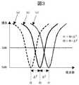
図3は本実施例における伝送損失の周波数特性であり、受信部20、アンテナ26、アンテナ27の共振周波数、送信部10の発振周波数の関係を示す。図中の(b)で示すように、受信部20の共振周波数、送信部10の発振周波数はf0である場合は、最も効率が良い。この状態の損失を0dBとする。アンテナ26の共振周波数はf0よりΔf高いf1、アンテナ27の共振周波数はf0よりΔf低いf2である。図中の(c)で示すようにアンテナ26の共振周波数f1の選択例として、(b)での損失がf0より高い側で3dBとなる周波数よりも高く、また図中の(a)で示すように、アンテナ27の共振周波数f2の選択例として、(b)での損失がf0より低い側で3dBとなる周波数よりも低く選択することにより、周波数ずれによる損失を最大3dBとすることが可能になる。周波数変動が大きい場合にはΔfを大きく、周波数変動が小さい場合にはΔfを小さくすることで、補正範囲を調整し、補正精度を上げることが望ましい。 FIG. 3 shows the frequency characteristics of transmission loss in this embodiment, and shows the relationship between the resonance frequency of the receiving
尚、f1、f2をf0からそれぞれ+Δf、−Δfとf0から等しい周波数差としたがこれに限らない。例えば、温度変動による発振周波数ずれにおおよそ見当が付く場合、それぞれf1=f0+Δfa、f2=f0−Δfbとf0からの周波数差を異なるものとしてもよい。また、f1及びf2の周波数は損失が3dBとなる周波数に限らないことは言うまでもない。 It should be noted that f1 and f2 are set to be equal frequency differences from f0 to + Δf and −Δf and f0, respectively, but are not limited thereto. For example, when the oscillation frequency shift due to temperature fluctuation is roughly estimated, the frequency difference from f1 = f0 + Δfa and f2 = f0−Δfb and f0 may be different. Needless to say, the frequencies of f1 and f2 are not limited to frequencies at which the loss is 3 dB.
次に本実施例を携帯端末に応用した例を挙げ詳細に説明する。
図4は携帯端末4、図5は携帯端末4に電力を供給する充電器5を示すブロック図である。携帯端末4は、本実施例の電力伝送装置に関わるものとして、受信ループ41、受信コイル42を有する受信部40、受信機43、制御部44、バッテリー45、アンテナ46、アンテナ47を有している。充電器5は送信ループ51、送信コイル52を有する送信部50と補正、発振機能を持つ送信機53、補正ループ54、ACアダプタ55を有している。Next, an example in which this embodiment is applied to a portable terminal will be described in detail.
FIG. 4 is a block diagram showing the
充電器5はACアダプタ55から供給される電力を、送信機53と送信部50を介して携帯端末4へ送信する。携帯端末4の受信部40で受信された充電器5からの電力は、携帯端末4の電源であるバッテリー45を充電する。
ここで、送信ループ51、送信コイル52を含む送信部50の発振周波数はf0であり、受信ループ41、受信コイル42を含む受信部40の共振周波数と送信部50の発振周波数が一致したとき、効率が最大となる。アンテナ46の共振周波数は共振周波数f0よりΔf高いf1であり、アンテナ47の共振周波数は共振周波数f0よりΔf低いf2である。さきに図2と図3を用いて説明した方法を適用し、受信機43におけるアンテナ46と47での受信レベルをもとに、制御部44で受信部40の共振周波数を制御することにより、電力の伝送損失を低減することができる。The
Here, the oscillation frequency of the
尚、図4の携帯端末は、例えば、携帯電話、PDA(Personal Digital Assistant)やPOS(Point Of Sale)端末などの携帯情報端末や、ノートパソコンなどの可搬、携帯出来るコンピュータ、災害救助ロボット等であっても良く、衣服や容器等に内蔵できるものでも良い。また、図5の充電器は前記と同様な端末、機器等に内蔵されるものでも良い。 4 is, for example, a portable information terminal such as a mobile phone, a PDA (Personal Digital Assistant) or a POS (Point Of Sale) terminal, a portable or portable computer such as a notebook computer, a disaster rescue robot, or the like. It may be a thing which can be built in clothes or a container. Further, the charger of FIG. 5 may be built in a terminal, a device, or the like similar to the above.
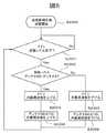
本実施例の電力伝送手順について図6のフローチャートを用いて説明する。まず始めに送信部50、送信機53の補正方法について説明する。充電器5の送信部50は、ACアダプタ55より得た送信機53からの供給電力により発振する。送信機53は補正用ループ54により取得した電力、位相、周波数等から送信部50の補正を行い、発振周波数をf0に合わせる。尚、補正には可変容量を変化させ周波数を調整し、補正時の送信電力を通常伝送時より低い最低限の出力とする。 The power transmission procedure of the present embodiment will be described with reference to the flowchart of FIG. First, a correction method for the
次に補正後の通常伝送時について、図6に基づき説明する。充電器5は発振周波数f0で発振し電力伝送を開始し、携帯端末4は電力の受電を開始する(ステップS1000)。携帯端末4の受信機43が受信ループ41、受信コイル42から供給される電力の低下を検知した場合には(ステップS1001のyes)、2つのアンテナ46、アンテナ47の受信レベルを比較する(ステップS1002)。アンテナ46、アンテナ47の受信レベルの差から受信部40の共振周波数ずれを補正する。例えば、送信部50で励起された発振周波数が高い方にずれている場合、共振周波数の高いアンテナ46の受信レベルが高くなる(ステップS1002のyes)。この場合、受信機43は受信ループ41、受信コイル42の共振周波数を高くするよう補正を行う(ステップS1003)。一方、送信部50で励起された発振共振周波数が低い方にずれている場合、共振周波数の低いアンテナ47の受信レベルが高くなる(ステップS1002のno)。この場合、受信機43は受信ループ41、受信コイル42の共振周波数を低くするよう補正を行う(ステップS1004)。なお、さきのステップS1001で受信コイル42から供給される電力の低下を検知しない場合には(ステップS1001のno)、引続き受信機43が電力の低下をモニタする。以上のフローは、電力の送受信動作が終了するまで継続しても良い。 Next, normal transmission after correction will be described with reference to FIG. The
以上の構成により、磁気共振方式において温度変化等による周波数ずれがあっても、効率の良い電力伝送が可能になる。
尚、共振周波数の補正は受信ループ41、受信コイル42のいずれか一方でもよく、受信ループ41、受信コイル42をそれぞれ独立に補正してもよい。また、アンテナ46、アンテナ47は他のシステムで使用しているアンテナでも良く、共振周波数の補正だけのために専用のアンテナを用いることに限定するものではない。例えば、GPS(Global Positioning System)、テレビ放送、非接触通信等で用いるアンテナでもよい。With the above configuration, even if there is a frequency shift due to a temperature change or the like in the magnetic resonance method, efficient power transmission becomes possible.
The resonance frequency may be corrected by either the
前記実施例1の電力伝送装置はアンテナの受信レベルにより受信ループ、受信コイルの共振周波数の補正を行っていたが、本実施例2ではこれに限らず、例えば共振周波数の補正量に併せて、各アンテナの共振周波数も同時に補正することによって、共振周波数の補正範囲が広くなり、より効率の高い電力伝送を可能にすることを特徴としている。前記実施例1の一変形例として、前記ループアンテナ、受信ループ、受信コイルを同心円状で同じ平面上に配置した例を挙げて説明する。 The power transmission device of the first embodiment corrects the resonance frequency of the reception loop and the reception coil according to the reception level of the antenna. However, the present embodiment is not limited to this. For example, in addition to the correction amount of the resonance frequency, By correcting the resonance frequency of each antenna at the same time, the correction range of the resonance frequency is widened, enabling more efficient power transmission. As a modification of the first embodiment, an example in which the loop antenna, the reception loop, and the reception coil are concentrically arranged on the same plane will be described.
図7は本発明の別な一実施例を示す電力伝送装置のブロック図である。図1と同様の構成要素で良いものには同じ番号を付している。同図において63は補正部64、比較部65を備える受信機であり、ループアンテナ66、ループアンテナ67は受信機63と接続される。ループアンテナ66は受信ループ21より径が小さく、受信ループ21、受信コイル22の共振周波数よりも共振周波数が高い(f1)。また、ループアンテナ67は受信ループ21より径が大きく、受信ループ21、受信コイル22の共振周波数よりも共振周波数が低い(f2)。また、これらのループアンテナを同一平面、同基板上に作成することにより、受信ループ21、ループアンテナ66、ループアンテナ67のそれぞれの周波数差Δfが、温度変化等の外乱があっても相対的にずれないため、本発明をより望ましい形態で実施することができる。 FIG. 7 is a block diagram of a power transmission device showing another embodiment of the present invention. Components that may be the same as those shown in FIG. In the figure,
図7では補正部64において、ループアンテナ66とループアンテナ67にも共振周波数を調整するための可変容量が設けられている。これにより受信ループ21、受信コイル22とともに、ループアンテナ66とループアンテナ67の共振周波数も同様に補正でき、これらの共振周波数が相対的にずれないようにしている。このほかの動作はさきの実施例1と同様であるので、詳しい説明を省略する。 In FIG. 7, in the
次に電力伝送手順について図8のフローチャートを用いて説明する。前記実施例1と同様に送信機の補正部は補正用ループにより補正を行い、送信機の発振周波数をf0に合わせる。受信機63の受信ループ21、受信コイル22は送信部により励起された磁界と磁気共振し、電力の受電を開始する(ステップS2000)。受信機63の比較部65は受信ループ21、受信コイル22から供給される電力の低下を検知した場合には(ステップS2001のyes)、ループアンテナ66、ループアンテナ67の受信レベルを比較する(ステップS2002)。受信レベルの差から受信ループ21、受信コイル22、ループアンテナ66、ループアンテナ67の共振周波数ずれを補正する。送信部で励起された発振周波数が高い方にずれている場合には、共振周波数の高いループアンテナ66の受信レベルが高くなる(ステップS2002のyes)。受信機63は受信ループ21、受信コイル22の共振周波数f0を高くするよう補正を行い(ステップS2003)、さらにはループアンテナ66、ループアンテナ67の共振周波数を高くする補正を行う(ステップS2004)。一方、送信部で励起された発振周波数が低い方にずれている場合、共振周波数の低いループアンテナ67の受信レベルが高くなる(ステップS2002のno)。受信機63は受信ループ21、受信コイル22の共振周波数を低くするよう補正を行い(ステップS2005)、さらにはループアンテナ66、ループアンテナ67の共振周波数を低くする補正を行う(ステップS2006)。共振周波数の補正は補正部64の可変容量を用いることで行う。なお、さきのステップS2001で受信コイル21から供給される電力の低下を検知しない場合には(ステップS2001のno)、引続き受信機63が電力の低下をモニタする。以上のフローは、電力の送受信動作が終了するまで継続しても良い。 Next, the power transmission procedure will be described with reference to the flowchart of FIG. As in the first embodiment, the correction unit of the transmitter performs correction using a correction loop, and adjusts the oscillation frequency of the transmitter to f0. The
以上の構成により、共振周波数の補正範囲が広がり、より温度変化等が厳しい条件下においても電力伝送の効率を向上させることが可能になる。
尚、補正に使用するループアンテナ66、ループアンテナ67の電力を加算し、効率の向上を図ってもよい。例えば、補正中はループアンテナ66、ループアンテナ67を受信レベルの比較に用い、補正時間以外では受信した電力を受信ループ21や受信コイル22で受信した電力と加算しても良い。また、受信機63へ供給される電力の低下を知るために、受信ループ21、受信コイル22の受電レベルを検知したが、受電を開始する際に限らず受信レベルを定期的に或いは随時に検知しても良い。また、前記実施例の説明では、円形のループアンテナ、受信ループや受信コイルを例として説明したが、本発明においては、円形にのみ限定されるものではなく例えば、方形であってもよい。With the configuration described above, the correction range of the resonance frequency is widened, and the efficiency of power transmission can be improved even under conditions where the temperature change is more severe.
The power of the loop antenna 66 and the
前記実施例1、前記実施例2の電力伝送装置は受信部の共振周波数より、共振周波数がそれぞれ高い方と低い方に異なる2つのアンテナを用い、受信部及び各アンテナ共振周波数の補正を行い、効率の向上を図ったが、本実施例3ではこれに限らず、異なる共振周波数を利用しデータ通信を可能にすることを特徴としている。 The power transmission device of the first embodiment and the second embodiment uses two different antennas for the resonance frequency higher and lower than the resonance frequency of the reception unit, respectively, and corrects the reception unit and each antenna resonance frequency. Although the efficiency is improved, the third embodiment is not limited to this, and is characterized by enabling data communication using different resonance frequencies.
図9は本発明のさらに別な一実施例を示す電力伝送装置のブロック図である。図9は図1に示した実施例1と同様な構成だが、送信機73に周波数変調部71、受信機83に処理部81を有する。なお、図示していないが送信機73には、発振周波数調整部17を図1と同様に有している。また、受信機83の処理部81は図1の比較部25の機能を併せて有している。ここでは送信部の発振周波数補正、受信部共振周波数の補正や電力の伝送については、前記実施例1と同様となるため説明を省略し、データ通信時について詳細に説明する。 FIG. 9 is a block diagram of a power transmission apparatus showing still another embodiment of the present invention. 9 has the same configuration as that of the first embodiment shown in FIG. 1, but includes a
データ通信について、前記した送信部の発振周波数補正を行った後、電力を伝送する前に行われる場合を例にして説明する。送信機73の周波数変調部71はメモリ72に記憶されたデータ70により時分割で発振周波数を切り替える。ここで入力データ70は“0”、“1”のデジタルデータである。ビットが“0”の場合、送信部10の発振周波数はf1、ビットが“1”の場合、送信部10の発振周波数はf2となるよう動作する。受信機83の処理部81は共振周波数がf1のアンテナ26、共振周波数がf2のアンテナ27の受信レベルを比較し、高い共振周波数を持つアンテナ26の受信レベルが高い場合、“0”、低い共振周波数を持つアンテナ27の受信レベルが高い場合、“1”と判断し、データ80をメモリ82に記憶する。このようにして、共振周波数の異なる二つのアンテナの受信レベルの違いを利用したデータ通信を行うことができる。 Data communication will be described by taking as an example a case where data transmission is performed after the oscillation frequency correction of the transmission unit is performed and before power is transmitted. The
次に本実施例を機器認証に用いた一例を示す。図10は、本発明のさらに別な一実施例を示すデータ通信のフローチャートであり、機器認証に利用した場合を示している。
送信機73は送信部10の発振周波数の補正を行う(ステップS3001)。電力伝送開始前に送信部10の発振周波数を機器認証情報であるデータ70に応じ、f1、f2と変化させ送信する(ステップS3002)。受信機83はアンテナ26とアンテナ27を用いて、これを受信する(ステップS3003)。受信機83の処理部81は前記したようにアンテナ26、アンテナ27の受信レベル変化から復調を行い、あらかじめメモリ82記憶されていた機器認証情報であるデータ80と比較して認証の可否を判定する(ステップS3004)。送信機73は前記のようにデータ70を送信した後、周波数f1又はf2のいずれか一方の搬送波を送信する(ステップS3005)。Next, an example in which this embodiment is used for device authentication will be described. FIG. 10 is a data communication flow chart showing still another embodiment of the present invention, and shows a case where it is used for device authentication.
The
ステップS3004で、受信したデータが前記データ80と一致することで認証可と判定された場合には(ステップS3004のyes)、受信機83はメモリ82に記憶された機器認証情報であるデータ80を送信機73へ送信する。このために例えば、ステップS3005で送信機73が周波数f1の搬送波を送信する場合にはアンテナ26の、周波数f2の搬送波を送信する場合にはアンテナ27のインピーダンスを変化させ、通称バックスキャッタ方式と呼ばれる方法で前記搬送波に対する負荷を変化させることで、前記データ80を送信機73へ送信する(ステップS3006)。 If it is determined in step S3004 that authentication is possible because the received data matches the data 80 (yes in step S3004), the
送信機73は、受信機83が行う例えばインピーダンス制御により変化する搬送波の反射量を送信部10で検出し(ステップS3007)、データの復調を行う(ステップS3008)。復調結果をメモリ72に記憶された機器認証情報であるデータ70と比較して認証の可否を判定する(ステップS3009)。これが一致して認証可と判定された場合には(図中のyes)、前記した電力伝送を開始する(ステップS3010)。電力の送受信動作が終了するまで動作が継続される。 The
ステップS3009で、送信機73の受信したデータが前記データ70と一致せず認証不可となった場合には(図中のno)、電力伝送を行うことなく動作を終了する。 In step S3009, if the data received by the
さきのステップS3004で、受信機83の受信したデータが前記データ80と一致せず認証不可となった場合には(図中のno)、受信機83は送信機73へデータを送信することなく、電力伝送も行うことなく動作を終了する。 In step S3004, if the data received by the
以上の動作でデータ通信が可能になり、例えば、機器認証等の通信により電力の受電を許された受信機にのみ電力を供給することができるため、セキュリティ等を向上させることができる。更には送信部や受信部の周波数補正を行うことにより電力伝送の効率を向上させることができる。また、無線伝送により電力の供給を受ける機器の利便性を向上することもできる。 Data communication is possible by the above operation. For example, power can be supplied only to a receiver that is permitted to receive power through communication such as device authentication, and thus security and the like can be improved. Furthermore, the efficiency of power transmission can be improved by correcting the frequency of the transmitter and receiver. In addition, the convenience of a device that receives power supply by wireless transmission can be improved.
尚、ここで受信部の第1のアンテナと第2のアンテナの受信レベル変化からデータを復調する例を示したが、これに限るものではない。例えば、ある受信レベルをしきい値とし、一方ないし双方の受信レベルをしきい値と比較して復調してもよい。また、受信側は送信側からの搬送波に対し、インピーダンスを変化させ、反射波を変調して応答するバックスキャッタ方式で通信を行う例を示したが、これに限らない。例えば、単一搬送波によるAM、FM変調等でもよい。 In addition, although the example which demodulates data from the reception level change of the 1st antenna and 2nd antenna of a receiving part was shown here, it does not restrict to this. For example, a certain reception level may be used as a threshold value, and one or both reception levels may be compared with the threshold value and demodulated. Moreover, although the receiving side showed the example which communicates by the backscatter system which changes an impedance with respect to the carrier wave from a transmission side, and responds by modulating a reflected wave, it is not restricted to this. For example, AM or FM modulation using a single carrier wave may be used.
また、前記した通信データは認証用のデータを送る場合を例に示したが、当然ながらこれに限定するものではない。例えば受信機83から送信機73へ、送信機73が送信する電力のレベルを指示するための情報を送っても良い。 Moreover, although the case where the above-mentioned communication data sends the data for authentication was shown as an example, naturally it is not limited to this. For example, information for instructing the level of power transmitted by the
さらには、受信部のアンテナの数を例えば26と27の2つとしたが、これに限らない。例えば、1つのアンテナを用いて受信レベルが高く又は低くなった場合のみ、補正するようにしてもよく、また3つ以上用いることで、補正精度の向上やデータ伝送速度の向上を図ってもよい。 Furthermore, although the number of antennas of the receiving unit is two, for example, 26 and 27, it is not limited to this. For example, correction may be performed only when the reception level is high or low using one antenna, and correction accuracy and data transmission speed may be improved by using three or more. .
このほか本実施例に対して、構成要素や動作の追加や変更を行った実施例が多数考えられるが、いずれも本発明の範疇にある。 In addition to the above, many examples in which components and operations are added or changed can be considered, but all fall within the scope of the present invention.
4:携帯端末、5:充電器、10:送信部、11,51:送信ループ、12,52:送信コイル、13,53,73:送信機、14,54:補正用ループ、15:補正部、20,40:受信部、21,41:受信ループ、22,42:受信コイル、23,63,83:受信機、24,64:補正部、25,65:比較部、26,27,46,47,66,67:アンテナ。 4: mobile terminal, 5: charger, 10: transmission unit, 11, 51: transmission loop, 12, 52: transmission coil, 13, 53, 73: transmitter, 14, 54: correction loop, 15:
Claims (7)
Translated fromJapanese前記送信装置は、
送信ループと送信コイルを含む前記電力を送信するための送信部と、
前記送信部に電力を供給する供給部と、前記送信部から送信した周波数を検出する検出部と、前記送信部より送信した周波数を補正する第1の補正部を備える送信機を有し、
前記受信装置は、
前記送信部より送信した電力を受信する受信ループと受信コイルを含む受信部と、
前記受信部の共振周波数より高い共振周波数を持つ第1のアンテナと、前記受信部の共振周波数より低い共振周波数を持つ第2のアンテナと、前記第1のアンテナと前記第2のアンテナの受信レベルを比較する比較部と、前記比較部での比較結果に基づき前記受信部の共振周波数を補正する第2の補正部を備える受信機を
有したことを特徴とする電力伝送装置。A power transmission device that transmits power from a transmission device to a reception device using magnetic resonance at a predetermined resonance frequency,
The transmitter is
A transmission unit for transmitting the power including a transmission loop and a transmission coil;
A transmitter including a supply unit that supplies power to the transmission unit, a detection unit that detects a frequency transmitted from the transmission unit, and a first correction unit that corrects the frequency transmitted from the transmission unit;
The receiving device is:
A receiving unit including a receiving loop and a receiving coil for receiving the power transmitted from the transmitting unit;
Reception levels of a first antenna having a resonance frequency higher than the resonance frequency of the reception unit, a second antenna having a resonance frequency lower than the resonance frequency of the reception unit, and the first antenna and the second antenna And a receiver including a second correction unit that corrects a resonance frequency of the reception unit based on a comparison result of the comparison unit.
前記送信機には前記受信機に送信するデジタルデータに応じて周波数を変化させる周波数変調部を有し、
前記受信機には前記第1のアンテナと前記第2のアンテナの受信レベルに基づきデジタルデータを復調する処理部を
有したことを特徴とする電力伝送装置。The power transmission device according to claim 1, further comprising:
The transmitter has a frequency modulation unit that changes a frequency according to digital data transmitted to the receiver,
The power transmission apparatus according to claim 1, wherein the receiver includes a processing unit that demodulates digital data based on reception levels of the first antenna and the second antenna.
前記電力を受信する受信ループと受信コイルを含む受信部と、A receiving section including a receiving loop and a receiving coil for receiving the power;
前記受信部の共振周波数より高い共振周波数を持つ第1のアンテナと、前記受信部の共振周波数より低い共振周波数を持つ第2のアンテナと、前記第1のアンテナと前記第2のアンテナの受信レベルを比較する比較部と、前記比較部での比較結果に基づき前記受信部の共振周波数を補正する第2の補正部を備える受信機をReception levels of a first antenna having a resonance frequency higher than the resonance frequency of the reception unit, a second antenna having a resonance frequency lower than the resonance frequency of the reception unit, and the first antenna and the second antenna A receiver comprising: a comparison unit that compares the resonance frequency of the reception unit based on a comparison result of the comparison unit;
有したことを特徴とする電力受信装置。A power receiving apparatus comprising:
Priority Applications (3)
| Application Number | Priority Date | Filing Date | Title |
|---|---|---|---|
| JP2008319857AJP5238472B2 (en) | 2008-12-16 | 2008-12-16 | Power transmission device and power reception device |
| CN2009102117095ACN101752913B (en) | 2008-12-16 | 2009-11-10 | Electric power transmitting device, sending device and receiving device |
| US12/618,998US8405486B2 (en) | 2008-12-16 | 2009-11-16 | Electric power transmitting and receiving device, electric power transmitting device and electric power receiving device |
Applications Claiming Priority (1)
| Application Number | Priority Date | Filing Date | Title |
|---|---|---|---|
| JP2008319857AJP5238472B2 (en) | 2008-12-16 | 2008-12-16 | Power transmission device and power reception device |
Publications (2)
| Publication Number | Publication Date |
|---|---|
| JP2010148174A JP2010148174A (en) | 2010-07-01 |
| JP5238472B2true JP5238472B2 (en) | 2013-07-17 |
Family
ID=42239803
Family Applications (1)
| Application Number | Title | Priority Date | Filing Date |
|---|---|---|---|
| JP2008319857AActiveJP5238472B2 (en) | 2008-12-16 | 2008-12-16 | Power transmission device and power reception device |
Country Status (3)
| Country | Link |
|---|---|
| US (1) | US8405486B2 (en) |
| JP (1) | JP5238472B2 (en) |
| CN (1) | CN101752913B (en) |
Families Citing this family (46)
| Publication number | Priority date | Publication date | Assignee | Title |
|---|---|---|---|---|
| US7886315B2 (en)* | 2007-01-30 | 2011-02-08 | Sony Corporation | Optical disc case, optical disc tray, card member, and manufacturing method |
| JP4393559B2 (en)* | 2008-02-28 | 2010-01-06 | 株式会社東芝 | Recording apparatus and broadcast receiving apparatus |
| US8878393B2 (en)* | 2008-05-13 | 2014-11-04 | Qualcomm Incorporated | Wireless power transfer for vehicles |
| US20090284369A1 (en) | 2008-05-13 | 2009-11-19 | Qualcomm Incorporated | Transmit power control for a wireless charging system |
| US20100201312A1 (en) | 2009-02-10 | 2010-08-12 | Qualcomm Incorporated | Wireless power transfer for portable enclosures |
| US9312924B2 (en) | 2009-02-10 | 2016-04-12 | Qualcomm Incorporated | Systems and methods relating to multi-dimensional wireless charging |
| US8854224B2 (en)* | 2009-02-10 | 2014-10-07 | Qualcomm Incorporated | Conveying device information relating to wireless charging |
| JP5476917B2 (en)* | 2009-10-16 | 2014-04-23 | Tdk株式会社 | Wireless power feeding device, wireless power receiving device, and wireless power transmission system |
| US20110221580A1 (en)* | 2010-03-12 | 2011-09-15 | Stmicroelectronics Asia Pacific Pte, Ltd. | Minimization of power consumption of remote controlled appliances |
| US9479225B2 (en)* | 2010-05-13 | 2016-10-25 | Qualcomm Incorporated | Resonance detection and control within a wireless power system |
| IT1400748B1 (en)* | 2010-06-30 | 2013-07-02 | St Microelectronics Srl | SYSTEM FOR WIRELESS TRANSFER OF ENERGY BETWEEN TWO DEVICES AND SIMULTANEOUS DATA TRANSFER. |
| KR101184503B1 (en) | 2010-08-13 | 2012-09-20 | 삼성전기주식회사 | Wireless power transmission apparatus and transmission method thereof |
| JP5152446B2 (en)* | 2010-12-01 | 2013-02-27 | トヨタ自動車株式会社 | Non-contact power supply equipment |
| JP2012118791A (en)* | 2010-12-01 | 2012-06-21 | Oki Electric Ind Co Ltd | Transaction apparatus, power feeding module and method of power feeding to electric element of transaction apparatus |
| KR101222749B1 (en) | 2010-12-14 | 2013-01-16 | 삼성전기주식회사 | Wireless power transmission apparatus and transmission method thereof |
| US20120153739A1 (en)* | 2010-12-21 | 2012-06-21 | Cooper Emily B | Range adaptation mechanism for wireless power transfer |
| WO2012086625A1 (en)* | 2010-12-21 | 2012-06-28 | 矢崎総業株式会社 | Power feed system |
| EP2659565B1 (en)* | 2010-12-31 | 2017-12-13 | Nokia Technologies Oy | Power transfer apparatus |
| JP2012143117A (en)* | 2011-01-06 | 2012-07-26 | Toyota Industries Corp | Non-contact power transmission device |
| JP2012178958A (en)* | 2011-02-28 | 2012-09-13 | Equos Research Co Ltd | Antenna |
| JP2012210118A (en)* | 2011-03-30 | 2012-10-25 | Equos Research Co Ltd | Antenna |
| US9391671B2 (en) | 2011-05-06 | 2016-07-12 | Samsung Electronics Co., Ltd. | Wireless power transmission and charging system and method thereof |
| RU2568606C2 (en)* | 2011-06-03 | 2015-11-20 | Тойота Дзидося Кабусики Кайся | Power contactless receiver and vehicle equipped therewith, power contactless transmitter and power contactless transmission system |
| KR101910379B1 (en)* | 2011-07-06 | 2018-10-22 | 엘지전자 주식회사 | Wireless power transmitter capable of bidirectional communication |
| KR101786945B1 (en)* | 2011-07-22 | 2017-10-19 | 한국전자통신연구원 | Power transmission apparatus and power reception apparatus |
| US9479227B2 (en) | 2011-09-13 | 2016-10-25 | Samsung Electronics Co., Ltd. | Wireless electromagnetic receiver and wireless power transfer system |
| CN103891098B (en)* | 2011-10-25 | 2016-08-24 | 金宣燮 | Contactless charging system and contactless charging method |
| WO2013089289A1 (en)* | 2011-12-13 | 2013-06-20 | 엘지전자 주식회사 | Method of modulating wireless power transmission signal |
| JP5915667B2 (en)* | 2012-01-31 | 2016-05-11 | 富士通株式会社 | Power transmission device, power transmission system, and power transmission method |
| KR101953913B1 (en)* | 2012-04-02 | 2019-03-04 | 엘에스전선 주식회사 | Device and System for Wireless Power Transmission using Transmission Coil Array |
| CN103679224A (en)* | 2012-09-24 | 2014-03-26 | 国民技术股份有限公司 | Radio frequency tag, mobile terminal, wireless communication system and radio frequency tag charging method |
| US20150236516A1 (en)* | 2012-10-11 | 2015-08-20 | Dsm Ip Assets B.V. | Wireless power transfer system |
| JP6036189B2 (en)* | 2012-11-07 | 2016-11-30 | ソニー株式会社 | ANTENNA MODULE, INFORMATION COMMUNICATION DEVICE, AND INFORMATION COMMUNICATION SYSTEM |
| KR101746318B1 (en) | 2013-01-29 | 2017-06-12 | 후지쯔 가부시끼가이샤 | Wireless power transfer system, power receiver, and wireless power transfer method |
| JP6145864B2 (en) | 2013-03-05 | 2017-06-14 | パナソニックIpマネジメント株式会社 | Non-contact power transmission device |
| CN105431993B (en)* | 2013-05-31 | 2019-05-10 | 诺基亚技术有限公司 | Multi-coil wireless power device |
| KR101994737B1 (en)* | 2014-08-19 | 2019-07-01 | 삼성전기주식회사 | Wireless charging apparatus and method for the same |
| CN105703491A (en)* | 2014-11-28 | 2016-06-22 | 微动公司 | Transmitter and transmitter group |
| US10110018B2 (en) | 2014-12-23 | 2018-10-23 | Intel Corporation | Wireless power repeating |
| US20160352133A1 (en)* | 2015-05-26 | 2016-12-01 | Intel Corporation | Wireless power transmitting coil disposed at an input device |
| US9866070B2 (en) | 2015-08-31 | 2018-01-09 | International Business Machines Corporation | Secure wireless power access protocol suited for implementing levels of service in public and private environments |
| WO2017057015A1 (en)* | 2015-09-29 | 2017-04-06 | ソニー株式会社 | Information processing device and method |
| US10686336B2 (en) | 2017-05-30 | 2020-06-16 | Wireless Advanced Vehicle Electrification, Inc. | Single feed multi-pad wireless charging |
| US11462943B2 (en) | 2018-01-30 | 2022-10-04 | Wireless Advanced Vehicle Electrification, Llc | DC link charging of capacitor in a wireless power transfer pad |
| KR102108826B1 (en)* | 2019-07-04 | 2020-05-11 | 엘지이노텍 주식회사 | Apparatus for receiving wireless power |
| CN111028496B (en)* | 2019-12-10 | 2021-04-27 | 东南大学 | A Long-distance LC Passive Wireless Sensing System with Automatic Frequency Matching |
Family Cites Families (11)
| Publication number | Priority date | Publication date | Assignee | Title |
|---|---|---|---|---|
| JP3648580B2 (en) | 1996-09-25 | 2005-05-18 | 松下電工株式会社 | Rechargeable electrical equipment |
| US6317027B1 (en)* | 1999-01-12 | 2001-11-13 | Randy Watkins | Auto-tunning scanning proximity reader |
| US7379774B2 (en)* | 2003-10-17 | 2008-05-27 | Alfred E. Mann Foundation For Scientific Research | Method and apparatus for efficient power/data transmission |
| US8102266B2 (en)* | 2005-01-21 | 2012-01-24 | Olympus Corporation | Radio intra-subject information acquiring system |
| US7825543B2 (en)* | 2005-07-12 | 2010-11-02 | Massachusetts Institute Of Technology | Wireless energy transfer |
| JP2008009910A (en)* | 2006-06-30 | 2008-01-17 | Citizen Holdings Co Ltd | Ic card and ic card reading system |
| US7683572B2 (en)* | 2006-11-10 | 2010-03-23 | Sanyo Electric Co., Ltd. | Battery charging cradle and mobile electronic device |
| JP2008141940A (en) | 2006-11-10 | 2008-06-19 | Sanyo Electric Co Ltd | Battery charging cradle and mobile electronic device |
| JP2008178195A (en)* | 2007-01-17 | 2008-07-31 | Seiko Epson Corp | Power transmission control device, power reception control device, non-contact power transmission system, power transmission device, power reception device, and electronic device |
| KR20110117732A (en)* | 2007-03-27 | 2011-10-27 | 메사추세츠 인스티튜트 오브 테크놀로지 | Wireless energy transfer |
| US9634730B2 (en)* | 2007-07-09 | 2017-04-25 | Qualcomm Incorporated | Wireless energy transfer using coupled antennas |
- 2008
- 2008-12-16JPJP2008319857Apatent/JP5238472B2/enactiveActive
- 2009
- 2009-11-10CNCN2009102117095Apatent/CN101752913B/enactiveActive
- 2009-11-16USUS12/618,998patent/US8405486B2/enactiveActive
Also Published As
| Publication number | Publication date |
|---|---|
| CN101752913B (en) | 2013-01-23 |
| JP2010148174A (en) | 2010-07-01 |
| US8405486B2 (en) | 2013-03-26 |
| US20100148939A1 (en) | 2010-06-17 |
| CN101752913A (en) | 2010-06-23 |
Similar Documents
| Publication | Publication Date | Title |
|---|---|---|
| JP5238472B2 (en) | Power transmission device and power reception device | |
| KR101480658B1 (en) | Wireless power utilization in a local computing environment | |
| US11081905B2 (en) | Information processing apparatus, information processing method, and information processing system | |
| EP2502328B1 (en) | Selective wireless power transfer | |
| EP2332098B1 (en) | Bidirectional wireless power transmission | |
| JP5241381B2 (en) | Power receiver | |
| US8803474B2 (en) | Optimization of wireless power devices | |
| US9935502B2 (en) | Detection and protection of devices within a wireless power system | |
| KR101709429B1 (en) | Power receiving device, receiving power regulation method, receiving power regulation program, and semiconductor device | |
| US20140252866A1 (en) | Presence and range detection of wireless power receiving devices and method thereof | |
| US20130187598A1 (en) | Apparatus and method for transmitting wireless power by using resonant coupling and system for the same | |
| US10374462B2 (en) | Energy transmission apparatus and method | |
| US20110198937A1 (en) | Impedance neutral wireless power receivers | |
| US20150303700A1 (en) | Power supply apparatus, control method, program, and storage medium | |
| KR101471806B1 (en) | Multi-adaptive switch apparatus of resonant wireless charging receiver and method thereof | |
| KR20150028042A (en) | Multi-mode wireless power receiver and wireless power receiving method thereof | |
| KR20140060186A (en) | Wireless power transfer apparatus having a plurality of power transmitter | |
| JP2016123162A (en) | Non-contact power supply system, power transmitter, and foreign matter detection method | |
| JP2009271920A (en) | Recharge of active transponder | |
| JP2016029577A (en) | Discovery method and program thereof | |
| JP5808849B1 (en) | Control method, contactless communication device, contactless power supply device, program, and drive circuit |
Legal Events
| Date | Code | Title | Description |
|---|---|---|---|
| A621 | Written request for application examination | Free format text:JAPANESE INTERMEDIATE CODE: A621 Effective date:20110322 | |
| A977 | Report on retrieval | Free format text:JAPANESE INTERMEDIATE CODE: A971007 Effective date:20121227 | |
| A131 | Notification of reasons for refusal | Free format text:JAPANESE INTERMEDIATE CODE: A131 Effective date:20130108 | |
| A521 | Request for written amendment filed | Free format text:JAPANESE INTERMEDIATE CODE: A523 Effective date:20130228 | |
| TRDD | Decision of grant or rejection written | ||
| A01 | Written decision to grant a patent or to grant a registration (utility model) | Free format text:JAPANESE INTERMEDIATE CODE: A01 Effective date:20130319 | |
| A61 | First payment of annual fees (during grant procedure) | Free format text:JAPANESE INTERMEDIATE CODE: A61 Effective date:20130401 | |
| R150 | Certificate of patent or registration of utility model | Free format text:JAPANESE INTERMEDIATE CODE: R150 Ref document number:5238472 Country of ref document:JP Free format text:JAPANESE INTERMEDIATE CODE: R150 | |
| FPAY | Renewal fee payment (event date is renewal date of database) | Free format text:PAYMENT UNTIL: 20160405 Year of fee payment:3 | |
| S111 | Request for change of ownership or part of ownership | Free format text:JAPANESE INTERMEDIATE CODE: R313113 | |
| R350 | Written notification of registration of transfer | Free format text:JAPANESE INTERMEDIATE CODE: R350 | |
| R250 | Receipt of annual fees | Free format text:JAPANESE INTERMEDIATE CODE: R250 | |
| R250 | Receipt of annual fees | Free format text:JAPANESE INTERMEDIATE CODE: R250 | |
| S111 | Request for change of ownership or part of ownership | Free format text:JAPANESE INTERMEDIATE CODE: R313111 | |
| R350 | Written notification of registration of transfer | Free format text:JAPANESE INTERMEDIATE CODE: R350 | |
| R250 | Receipt of annual fees | Free format text:JAPANESE INTERMEDIATE CODE: R250 | |
| R250 | Receipt of annual fees | Free format text:JAPANESE INTERMEDIATE CODE: R250 | |
| R250 | Receipt of annual fees | Free format text:JAPANESE INTERMEDIATE CODE: R250 | |
| R250 | Receipt of annual fees | Free format text:JAPANESE INTERMEDIATE CODE: R250 | |
| S111 | Request for change of ownership or part of ownership | Free format text:JAPANESE INTERMEDIATE CODE: R313111 | |
| R350 | Written notification of registration of transfer | Free format text:JAPANESE INTERMEDIATE CODE: R350 | |
| R250 | Receipt of annual fees | Free format text:JAPANESE INTERMEDIATE CODE: R250 | |
| R250 | Receipt of annual fees | Free format text:JAPANESE INTERMEDIATE CODE: R250 | |
| R250 | Receipt of annual fees | Free format text:JAPANESE INTERMEDIATE CODE: R250 | |
| R250 | Receipt of annual fees | Free format text:JAPANESE INTERMEDIATE CODE: R250 |