JP5237978B2 - Imaging apparatus and imaging method, and image processing method for the imaging apparatus - Google Patents
Imaging apparatus and imaging method, and image processing method for the imaging apparatusDownload PDFInfo
- Publication number
- JP5237978B2 JP5237978B2JP2010029039AJP2010029039AJP5237978B2JP 5237978 B2JP5237978 B2JP 5237978B2JP 2010029039 AJP2010029039 AJP 2010029039AJP 2010029039 AJP2010029039 AJP 2010029039AJP 5237978 B2JP5237978 B2JP 5237978B2
- Authority
- JP
- Japan
- Prior art keywords
- image
- imaging
- image sensor
- focus
- sensor
- Prior art date
- Legal status (The legal status is an assumption and is not a legal conclusion. Google has not performed a legal analysis and makes no representation as to the accuracy of the status listed.)
- Active
Links
Images


Classifications
- H—ELECTRICITY
- H04—ELECTRIC COMMUNICATION TECHNIQUE
- H04N—PICTORIAL COMMUNICATION, e.g. TELEVISION
- H04N1/00—Scanning, transmission or reproduction of documents or the like, e.g. facsimile transmission; Details thereof
- H04N1/40—Picture signal circuits
- H04N1/409—Edge or detail enhancement; Noise or error suppression
- H04N1/4092—Edge or detail enhancement
- G—PHYSICS
- G02—OPTICS
- G02B—OPTICAL ELEMENTS, SYSTEMS OR APPARATUS
- G02B27/00—Optical systems or apparatus not provided for by any of the groups G02B1/00 - G02B26/00, G02B30/00
- G02B27/64—Imaging systems using optical elements for stabilisation of the lateral and angular position of the image
- G02B27/646—Imaging systems using optical elements for stabilisation of the lateral and angular position of the image compensating for small deviations, e.g. due to vibration or shake
- G—PHYSICS
- G06—COMPUTING OR CALCULATING; COUNTING
- G06T—IMAGE DATA PROCESSING OR GENERATION, IN GENERAL
- G06T5/00—Image enhancement or restoration
- G06T5/73—Deblurring; Sharpening
- H—ELECTRICITY
- H04—ELECTRIC COMMUNICATION TECHNIQUE
- H04N—PICTORIAL COMMUNICATION, e.g. TELEVISION
- H04N23/00—Cameras or camera modules comprising electronic image sensors; Control thereof
- H04N23/45—Cameras or camera modules comprising electronic image sensors; Control thereof for generating image signals from two or more image sensors being of different type or operating in different modes, e.g. with a CMOS sensor for moving images in combination with a charge-coupled device [CCD] for still images
- H—ELECTRICITY
- H04—ELECTRIC COMMUNICATION TECHNIQUE
- H04N—PICTORIAL COMMUNICATION, e.g. TELEVISION
- H04N23/00—Cameras or camera modules comprising electronic image sensors; Control thereof
- H04N23/60—Control of cameras or camera modules
- H—ELECTRICITY
- H04—ELECTRIC COMMUNICATION TECHNIQUE
- H04N—PICTORIAL COMMUNICATION, e.g. TELEVISION
- H04N23/00—Cameras or camera modules comprising electronic image sensors; Control thereof
- H04N23/60—Control of cameras or camera modules
- H04N23/68—Control of cameras or camera modules for stable pick-up of the scene, e.g. compensating for camera body vibrations
- H04N23/682—Vibration or motion blur correction
- H04N23/683—Vibration or motion blur correction performed by a processor, e.g. controlling the readout of an image memory
- G—PHYSICS
- G06—COMPUTING OR CALCULATING; COUNTING
- G06T—IMAGE DATA PROCESSING OR GENERATION, IN GENERAL
- G06T2207/00—Indexing scheme for image analysis or image enhancement
- G06T2207/20—Special algorithmic details
- G06T2207/20172—Image enhancement details
- G06T2207/20201—Motion blur correction
Landscapes
- Engineering & Computer Science (AREA)
- Multimedia (AREA)
- Signal Processing (AREA)
- Physics & Mathematics (AREA)
- General Physics & Mathematics (AREA)
- Optics & Photonics (AREA)
- Human Computer Interaction (AREA)
- Theoretical Computer Science (AREA)
- Studio Devices (AREA)
- Image Processing (AREA)
- Facsimile Image Signal Circuits (AREA)
Description
Translated fromJapaneseこの発明は、リンギング除去のための画像処理装置および画像処理方法に関する。 The present invention relates to an image processing apparatus and an image processing method for removing ringing.
デジタルカメラで画像を撮像すると、CCD(Charge−Coupled Device)、あるいはCMOSの読み出し回路の特性や伝送路の特性により画像にノイズが加わることがある。また、撮像時にフォーカスが合っていないこと(焦点外れ:out−of−focus)による画像のぼやけ(ブラー:blur)や、手振れ(camera shake)などによる画像のぼやけが発生する。このように撮像画像には、撮像画像固有の特性によるノイズに、撮影時の人為的な操作を起因とするぼやけが加わることにより、画像が劣化することになる。これらの「ぼやけ」のうち、撮影(露光)中におけるカメラの運動による画像のぼやけを「ブレ(motion blur)」と称し、焦点外れによるぼやけ(out−of−focus blur)と区別することにする。 When an image is captured by a digital camera, noise may be added to the image due to the characteristics of a CCD (Charge-Coupled Device) or CMOS readout circuit and the characteristics of a transmission path. In addition, image blur due to out of focus (out-of-focus) at the time of image capturing or image blur due to camera shake or the like occurs. In this way, in the captured image, the image is deteriorated due to the noise caused by the artificial operation at the time of photographing being added to the noise due to the characteristic unique to the captured image. Among these “blurs”, image blur due to camera movement during shooting (exposure) is referred to as “motion blur” and is distinguished from out-of-focus blur. .
近年、特に高感度撮影の需要が増大していることにより、ぼやけによって劣化した画像(以下、「劣化画像」という)を元の画像(以下、「理想画像」という)にできるだけ近い画像に復元することが必要となる。高感度撮影に要求される、明るくノイズやぼやけのない画像を実現するために、大別して感度をあげるという考え方と、露光時間を長くするという考え方がある。 In recent years, especially due to the increasing demand for high-sensitivity shooting, an image degraded by blur (hereinafter referred to as “degraded image”) is restored to an image as close as possible to the original image (hereinafter referred to as “ideal image”). It will be necessary. In order to realize a bright and noise-free image required for high-sensitivity shooting, there are a concept of broadly increasing sensitivity and a concept of increasing the exposure time.
しかしながら、感度を高めるとノイズも増幅してしまう、そのため、信号がノイズに埋もれてしまい、ノイズが大半を占める画像になることが多い。一方で露光時間を長くすることで、その場で生じる光を多く蓄積し、ノイズの少ない画像が得られる。この場合、信号がノイズで埋もれることはないが、手振れによって画像にブレが生じるという問題がある。 However, when the sensitivity is increased, the noise is also amplified. For this reason, the signal is buried in the noise, and the image occupies most of the noise in many cases. On the other hand, by increasing the exposure time, a lot of light generated on the spot is accumulated and an image with less noise can be obtained. In this case, the signal is not buried with noise, but there is a problem that the image is blurred due to camera shake.
そこで、従来、2通りの考え方で露光時間を長くする場合の対処法がとられていた。一つは、レンズシフトやセンサシフトといった光学式手振れ補正である。他方は、得られた画像からブレの方向/大きさを求め、そこから信号処理によって画像を復元するという方法(信号処理による復元方法)である。信号処理による復元方法は、例えば特許文献1、特許文献2、非特許文献1〜5などに開示されている。 In view of this, conventionally, there have been two ways of dealing with the case where the exposure time is increased. One is optical camera shake correction such as lens shift and sensor shift. The other is a method (restoration method by signal processing) in which the direction / size of blur is obtained from the obtained image and the image is restored therefrom by signal processing. For example, Patent Document 1, Patent Document 2, and Non-Patent Documents 1 to 5 disclose a restoration method using signal processing.
光学式手振れ補正は、補正範囲に限界があるため、従来よりも暗い環境で十分な光量を集める場合、稼動範囲が大きくなければならない。しかし、大きくなると移動の際の時間遅れが生じ、また、大型化にはサイズの物理的な限界がある。 Since optical camera shake correction has a limit in the correction range, when collecting a sufficient amount of light in a darker environment than before, the operating range must be large. However, when it becomes larger, a time delay occurs during movement, and there is a physical limit of size for enlargement.
また、信号処理によって、劣化画像から理想画像を復元する方法では、復元された画像にリンギングなどのノイズが発生してしまうという問題がある。「リンギング(ringing)」とは、画像において輝度などが一様な部分(平坦部)が平坦に見えないノイズである。 Further, in the method of restoring an ideal image from a deteriorated image by signal processing, there is a problem that noise such as ringing occurs in the restored image. “Ringing” is noise in which a portion (flat portion) having a uniform luminance or the like in an image does not appear flat.
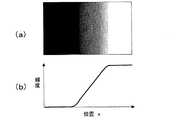
図1(a)は、輝度がステップ状に変化する画像(エッジ付近の理想画像)を示す平面図であり、図1(b)は、その輝度分布を模式的に示すグラフである。図2(a)は、図1(a)の画像をカメラで撮影することによって得られた劣化画像(ぼやけ画像:blurred image)を示す平面図であり、図2(b)は、その輝度分布を模式的に示すグラフである。これは、カメラ撮影に際して、水平横方向に手振れが生じたものとする。図2(a)の劣化画像は、手振れによるぼやけ(ブレ)が発生したため、エッジのシャープネスが失われている。図3(a)は、図2(a)の劣化画像を信号処理によって復元した画像を示す平面図であり、図3(b)は、復元画像の輝度分布を模式的に示すグラフである。図3(a)の復元画像には、輝度が周期的に変化する部分が存在している。このような輝度変化が「リンギング」と称されるノイズである。 FIG. 1A is a plan view showing an image (ideal image near the edge) in which the luminance changes stepwise, and FIG. 1B is a graph schematically showing the luminance distribution. FIG. 2A is a plan view showing a deteriorated image (blurred image) obtained by taking the image of FIG. 1A with a camera, and FIG. 2B shows its luminance distribution. Is a graph schematically showing It is assumed that camera shake occurs in the horizontal and horizontal directions during camera shooting. In the deteriorated image in FIG. 2A, the sharpness of the edge is lost because blurring due to camera shake occurs. FIG. 3A is a plan view showing an image obtained by restoring the deteriorated image of FIG. 2A by signal processing, and FIG. 3B is a graph schematically showing the luminance distribution of the restored image. In the restored image in FIG. 3A, there is a portion where the luminance changes periodically. Such a luminance change is noise called “ringing”.
特許文献1に示される方法では、エッジ近辺で発生するリンギングをおさえるように、エッジ近辺では復元された結果を利用せず、ぼやけ画像のデータを利用している。この方法では、画面内のエッジの強度に基づいて、ぼやけ画像のデータを利用する重みを決めている。しかしながら、手振れの量が決まらなければ、エッジの強度を決めることができない。エッジの強度が決まらなければ、ぼやけ画像のデータを利用する重みを決めることができない。そのため、リンギングを除去できないという問題があった。 In the method disclosed in Patent Document 1, the blurred image data is used instead of the restored result in the vicinity of the edge so as to suppress the ringing generated in the vicinity of the edge. In this method, the weight for using blurred image data is determined based on the strength of the edge in the screen. However, the edge strength cannot be determined unless the amount of camera shake is determined. If the edge strength is not determined, the weight for using the blurred image data cannot be determined. Therefore, there is a problem that ringing cannot be removed.
本発明は、上記課題を解決するためになされたものであり、人間の知覚特性を考慮して、画像の平坦部におけるリンギングを低減させる画像処理を行う撮像装置を提供することにある。 The present invention has been made to solve the above-described problems, and provides an imaging apparatus that performs image processing that reduces ringing in a flat portion of an image in consideration of human perceptual characteristics.
本発明の撮像装置は、第1撮像素子および第2撮像素子と、前記第1撮像素子の撮像面上に焦点が合っている第1の像を形成し、かつ、前記第2撮像素子の撮像面上に焦点が外れた第2の像を形成し得る光学系と、前記第1撮像素子および前記第2撮像素子から得られる信号を処理する画像処理部とを備え、前記画像処理部は、前記第1撮像素子および第2撮像素子によって取得された画像から、手振れによるぼやけおよび焦点外れによるぼやけを減少させた復元画像を生成する。 The imaging device of the present invention forms a first image focused on the imaging surface of the first imaging element and the second imaging element, and the imaging of the second imaging element. An optical system capable of forming a second image out of focus on the surface, and an image processing unit that processes signals obtained from the first imaging element and the second imaging element, and the image processing unit includes: From the images acquired by the first image sensor and the second image sensor, a restored image in which blur due to camera shake and blur due to defocus is reduced is generated.
好ましい実施形態において、前記第2撮像素子における焦点外れによるぼやけを規定する点拡がり関数を記録するメモリを備え、前記画像処理部は、撮像時における焦点外れによるぼやけを規定する点拡がり関数を前記メモリから読み出し、復元画像の生成に用いる。 In a preferred embodiment, the image processing unit includes a memory that records a point spread function that defines blur due to defocusing in the second image sensor, and the image processing unit stores the point spread function that defines blur due to defocus during imaging. Used to generate a restored image.
好ましい実施形態において、前記光学系は、結像レンズと、前記結像レンズを透過した光を2方向に分離する光スプリッタとを有しており、分離された一方の光を前記第1撮像素子に入射し、かつ、分離された他方の光を前記第2撮像素子に入射する。 In a preferred embodiment, the optical system includes an imaging lens and an optical splitter that separates light transmitted through the imaging lens in two directions, and the separated one light is transmitted to the first imaging element. And the other separated light is incident on the second image sensor.
好ましい実施形態において、前記結像レンズから前記第1撮像素子までの光学的な距離は、前記結像レンズから前記第2撮像素子までの光学的な距離とは異なっている。 In a preferred embodiment, an optical distance from the imaging lens to the first imaging element is different from an optical distance from the imaging lens to the second imaging element.
好ましい実施形態において、前記光学系は、入射光を2方向に分離する光スプリッタと、分離された一方の光を前記第1撮像素子上に集光する第1結像レンズと、分離された他方の光を前記第2撮像素子上に集光する第2結像レンズとを有している。 In a preferred embodiment, the optical system includes an optical splitter that separates incident light in two directions, a first imaging lens that condenses the separated light on the first image sensor, and the other separated light. And a second imaging lens that condenses the light on the second image sensor.
好ましい実施形態において、表示部を更に備え、前記第1撮像素子によって取得された画像を前記表示部に表示する。 In a preferred embodiment, a display unit is further provided, and an image acquired by the first image sensor is displayed on the display unit.
本発明のプログラムは、第1撮像素子および第2撮像素子と、前記第1撮像素子の撮像面上に焦点が合っている第1の像を形成し、かつ、前記第2撮像素子の撮像面上に焦点が外れた第2の像を形成する光学系と、前記第1撮像素子および前記第2撮像素子から得られる信号を処理する画像処理部とを備える撮像装置の動作を制御するプログラムであって、前記光学系により、前記第1撮像素子の撮像面上に焦点が合っている第1の像を形成させるとともに、前記第2撮像素子の撮像面上に焦点が合っていない第2の像を形成させるステップと、前記画像処理部により、前記第1撮像素子および前記第2撮像素子によって取得された画像から、手振れによるぼやけおよび焦点外れによるぼやけを減少させた復元画像を生成するステップとを実行する。 The program of the present invention forms a first image focused on the imaging surface of the first imaging device and the second imaging device, and the imaging surface of the second imaging device. A program for controlling the operation of an imaging apparatus including an optical system that forms a second image that is out of focus and an image processing unit that processes a signal obtained from the first imaging element and the second imaging element. In addition, the optical system forms a first image that is in focus on the imaging surface of the first image sensor, and a second that is not in focus on the image surface of the second image sensor. An image forming step, and a step of generating a restored image in which blur due to camera shake and blur due to defocus are reduced from the images acquired by the first image sensor and the second image sensor by the image processor. The fruit To.
本発明の画像処理方法は、第1撮像素子および第2撮像素子と、前記第1撮像素子の撮像面上に焦点が合っている第1の像を形成し、かつ、前記第2撮像素子の撮像面上に焦点が外れた第2の像を形成する光学系と、前記第1撮像素子および前記第2撮像素子から得られる信号を処理する画像処理部とを備える撮像装置における画像処理方法であって、前記光学系により、前記第1撮像素子の撮像面上に焦点が合っている第1の像を形成させるとともに、前記第2撮像素子の撮像面上に焦点が合っていない第2の像を形成させるステップと、前記画像処理部により、前記第1撮像素子および前記第2撮像素子によって取得された画像から、手振れによるぼやけおよび焦点外れによるぼやけを減少させた復元画像を生成するステップとを含む。 The image processing method of the present invention forms a first image focused on the imaging surface of the first image sensor and the second image sensor, and the second image sensor. An image processing method in an imaging apparatus, comprising: an optical system that forms a second image out of focus on an imaging surface; and an image processing unit that processes a signal obtained from the first imaging element and the second imaging element. In addition, the optical system forms a first image that is in focus on the imaging surface of the first image sensor, and a second that is not in focus on the image surface of the second image sensor. An image forming step, and a step of generating a restored image in which blur due to camera shake and blur due to defocus are reduced from the images acquired by the first image sensor and the second image sensor by the image processor. including.
本発明の他の画像処理方法は、第1撮像素子および第2撮像素子と、前記第1撮像素子の撮像面上に焦点が合っている第1の像を形成し、かつ、前記第2撮像素子の撮像面上に焦点が外れた第2の像を形成する光学系と、前記第1撮像素子および前記第2撮像素子から得られる信号を処理する画像処理部とを備える撮像装置における画像処理方法であって、前記光学系により、前記第1撮像素子の撮像面上に焦点が合っていない第1の像を形成させるとともに、前記第2撮像面上にも焦点が合っていない第2の像を形成させるステップと、前記画像処理部により、前記第1撮像素子および前記第2撮像素子によって取得された画像から、手振れによるぼやけおよび焦点外れによるぼやけを減少させた復元画像を生成するステップとを含む。 According to another image processing method of the present invention, a first image sensor, a second image sensor, and a first image focused on an imaging surface of the first image sensor are formed, and the second image sensor is formed. Image processing in an imaging apparatus comprising: an optical system that forms a second image out of focus on the imaging surface of the element; and an image processing unit that processes a signal obtained from the first imaging element and the second imaging element In the method, the optical system forms a first image that is not focused on the imaging surface of the first image sensor, and the second image that is not focused on the second imaging surface. An image forming step, and a step of generating a restored image in which blur due to camera shake and blur due to defocus are reduced from the images acquired by the first image sensor and the second image sensor by the image processor. including.
この発明によれば、特に画像の平坦部分におけるリンギングを低減させることが可能となる。 According to the present invention, it is possible to reduce ringing particularly in a flat portion of an image.
本発明の実施形態を説明する前に、本発明の基本的原理を説明する。 Before describing the embodiment of the present invention, the basic principle of the present invention will be described.
本明細書では、撮像面に形成される画像の輝度分布をi(x,y)で表すことにする。座標(x,y)は、撮像面の画素(光感知セル)の位置を示す二次元座標である。画像が例えば行列状に配列されたM×N個の画素からなる場合において、xおよびyが、それぞれ、0≦x≦M−1、0≦y≦N−1の関係を満足する整数であるとすると、画像を構成する個々の画素の位置を座標(x,y)によって特定することができる。ここでは、座標の原点(0、0)を画像の左上隅に置き、x軸は垂直方向、y軸は水平方向に延びるものとする。ただし、座標の取り方は、任意である。 In this specification, the luminance distribution of an image formed on the imaging surface is represented by i (x, y). The coordinates (x, y) are two-dimensional coordinates indicating the position of the pixel (photosensitive cell) on the imaging surface. For example, when the image is composed of M × N pixels arranged in a matrix, x and y are integers that satisfy the relationship of 0 ≦ x ≦ M−1 and 0 ≦ y ≦ N−1, respectively. Then, the position of each pixel constituting the image can be specified by coordinates (x, y). Here, the origin of coordinates (0, 0) is placed at the upper left corner of the image, and the x axis extends in the vertical direction and the y axis extends in the horizontal direction. However, the method of taking the coordinates is arbitrary.
ぼやけ(blur)のない画像(理想画像または元画像)の輝度分布をs(x,y)とし、ぼやけを規定するPSF、すなわち「点拡がり関数(Point Spread Function)」をf(x,y)とすると、以下の式1が成立する。
ここで、記号「*」は、畳み込み演算(コンボリューション)を示している。式1は、一般に、以下の式2で表される。
画像が、M×N個の画素からなる場合、上記の式2は、以下の式3で表すことができる。
ぼやけの点拡がり関数PSFである関数f(x,y)が既知であると、カメラ撮影によって得られた画像i(x,y)に対する逆畳み込み演算(デコンボリューション)により、ぼやけの無い画像s(x,y)を復元することができる。また、f(x,y)が既知でない場合は、画像からf(x,y)を推定した上でs(x,y)を求める必要がある。 If the function f (x, y), which is the blur point spread function PSF, is known, a blur-free image s () is obtained by a deconvolution operation (deconvolution) on the image i (x, y) obtained by camera shooting. x, y) can be restored. If f (x, y) is not known, it is necessary to obtain s (x, y) after estimating f (x, y) from the image.
一般に、2つの関数の畳み込みのフーリエ変換は、各関数のフーリエ変換の積によって表される。このため、i(x,y)、s(x,y)、f(x,y)のフーリエ変換を、それぞれ、I(u,v)、S(u,v)、F(u,v)で表すと、式1から、以下の式4が導かれる。なお、(u,v)は、周波数空間における座標であり、それぞれ、実画像におけるx方向およびy方向の空間周波数に対応している。
ここで、記号「・」は、周波数空間における関数の「積」を示している。式(4)を変形すると、以下の式5が得られる。
この式5は、カメラ撮影によって得られた画像i(x,y)のフーリエ変換I(u,v)を、点拡がり関数PSFであるf(x,y)のフーリエ変換F(u,v)で除算して得られた関数が、理想画像s(x,y)のフーリエ変換S(u,v)に相当することを示している。すなわち、I(u,v)およびf(u,v)が求まれば、S(u,v)を決定できる。I(u,v)は、カメラ撮影によって得られた画像(劣化画像)をフーリエ変換したものであるため、手振れの点拡がり関数PSFを表すf(x,y)が求まれば、信号処理によって劣化画像から画像を復元する(真の画像に近づける)ことが可能になる。 This equation 5 expresses the Fourier transform I (u, v) of the image i (x, y) obtained by camera photographing, and the Fourier transform F (u, v) of f (x, y) which is a point spread function PSF. It is shown that the function obtained by dividing by is equivalent to the Fourier transform S (u, v) of the ideal image s (x, y). That is, if I (u, v) and f (u, v) are obtained, S (u, v) can be determined. Since I (u, v) is a Fourier transform of an image (degraded image) obtained by camera shooting, if f (x, y) representing a hand-shaking point spread function PSF is obtained, signal processing is performed. It is possible to restore an image from a deteriorated image (close to a true image).
手振れの点拡がり関数PSFを表すf(x,y)は、撮影(露光)中における手振れの軌道に依存する。言い換えると、手振れの軌道はカメラ撮影毎に異なるため、f(x,y)もカメラ撮影毎に変化する。f(x,y)は、カメラ撮影によって得られた1枚または複数枚の画像から推定することも可能であるが、撮影(露光)中におけるカメラの動き(手振れ軌跡)をセンサによって検出して推定することも可能である。しかし、f(x,y)は、推定または測定によって得られるものに過ぎず、何らかの誤差を含む。このため、理想画像s(x,y)を完全に復元することは困難である。 The f (x, y) representing the camera shake point spread function PSF depends on the camera shake trajectory during photographing (exposure). In other words, since the hand movement trajectory differs for each camera shot, f (x, y) also changes for each camera shot. Although f (x, y) can be estimated from one or a plurality of images obtained by camera shooting, the camera movement (camera shake trajectory) during shooting (exposure) is detected by a sensor. It is also possible to estimate. However, f (x, y) is only obtained by estimation or measurement and includes some error. For this reason, it is difficult to completely restore the ideal image s (x, y).
非特許文献2は、短い露光時間中における手振れの軌道を「等速直線運動」と仮定することにより、その点拡がり関数PSFのフーリエ変換をsinc関数で近似することを開示している。手振れの幅をW、手振れの方向をx軸方向とすると、式5の分母であるF(u,v)は、以下の式6で示される。
式6の右辺は、sinc(ジンク)関数であり、その振幅は一定周期毎にゼロ(0)となる。この周期は、手振れの幅Wの逆数(1/W)である。なお、手振れの方向がx軸に対してθの角度を向く場合、F(u、v)は、式6の関数を角度θだけ回転させたものとなる。現実の手振れは、複雑な軌道を描くため、「等速直線運動」の仮定が充分に成立しない場合がある。 The right side of Equation 6 is a sinc (zinc) function, and its amplitude becomes zero (0) at every fixed period. This period is the reciprocal (1 / W) of the width W of camera shake. When the direction of camera shake is directed to the angle θ with respect to the x-axis, F (u, v) is obtained by rotating the function of Expression 6 by the angle θ. Since an actual hand shake draws a complicated trajectory, the assumption of “constant linear motion” may not be sufficiently established.
本発明者は、式5の分母であるF(u,v)が低周波数領域で周期的にゼロとなることが、画像の平坦部におけるリンギングの主たる発生原因であることに着目し、本発明を完成した。ここで、「低周波数領域」とは、周波数空間において原点に近い領域であり、画像において輝度分布の空間周波数が相対的に低い領域である。このような低周波数領域は、画像の平坦部(輝度変化が少ない部分)に相当する。 The inventor of the present invention pays attention to the fact that F (u, v), which is the denominator of Equation 5, periodically becomes zero in the low frequency region, is the main cause of ringing in the flat portion of the image. Was completed. Here, the “low frequency region” is a region close to the origin in the frequency space, and is a region where the spatial frequency of the luminance distribution is relatively low in the image. Such a low-frequency region corresponds to a flat portion (a portion where the luminance change is small) of the image.
本発明では、低周波数領域でF(u,v)がゼロにならないような撮像を実現することにより、手振れなどを原因とする劣化画像を復元するに際して画像の平坦部(低空間周波数領域)におけるリンギングを低減することが可能になる。人の目には、画像の平坦部におけるリンギングが目立つため、平坦部でのリンギングを低減すれば、画像の質は格段に向上する。 In the present invention, by realizing imaging in which F (u, v) does not become zero in the low frequency region, when restoring a deteriorated image caused by camera shake or the like, in a flat portion (low spatial frequency region) of the image It is possible to reduce ringing. Since the ringing in the flat part of the image is conspicuous for human eyes, the quality of the image is remarkably improved if the ringing in the flat part is reduced.
本発明の好ましい実施形態では、カメラ撮影に際して、焦点外れによるぼやけを意図的に画像に付与する。好ましい実施形態では、後述するように、1つの撮像素子で焦点外れによるぼやけのない画像を取得するとともに、他の撮像素子で意図的に焦点外れによるぼやけのある画像を取得する。そして、これらの撮像素子から得られる画像信号を合成することにより1つの劣化画像を生成する。この劣化画像には、撮影時に手振れが発生した場合、手振れによるぼやけと焦点外れによるぼやけとが重畳したぼやけが発生している。なお、好ましい実施形態において、焦点外れのぼやけを示す点拡がり関数PSFは既知である。 In a preferred embodiment of the present invention, blurring due to defocusing is intentionally added to an image during camera shooting. In a preferred embodiment, as will be described later, an image without blur due to defocusing is acquired by one image sensor, and an image with blur due to defocus is intentionally acquired by another image sensor. Then, one deteriorated image is generated by synthesizing image signals obtained from these imaging elements. In the deteriorated image, when camera shake occurs at the time of shooting, blur is generated by superimposing blur due to camera shake and blur due to defocusing. Note that in a preferred embodiment, the point spread function PSF indicating defocus blur is known.
本明細書では、手振れによるぼやけの点拡がり関数PSFをf1(x,y)で表し、焦点外れによるぼやけの点拡がり関数PSFをf2(x,y)で表す。この場合、式1、式4、式5は、それぞれ、以下の式7、式8、式9に変形される。
ここで、F1(u,v)およびF2(u,v)は、それぞれ、f1(x,y)およびf2(x,y)のフーリエ変換である。Here, F1 (u, v) and F2 (u, v) are Fourier transforms of f1 (x, y) and f2 (x, y), respectively.
本発明の好ましい実施形態において、画像に意図的に付与した焦点外れによるぼやけの点拡がり関数PSF、すなわちf2(x,y)は、既知である。一般に、焦点外れによるぼやけの点拡がり関数PSFは、ピルボックス(pillbox)関数やガウス関数(Gaussian)によって表現され得る。このような関数のフーリエ変換は、焦点外れの程度を適切に調整する限り、周波数ゼロの近傍、すなわち低周波数領域ではゼロにはならない。In a preferred embodiment of the present invention, the image intentionally imparted to the point spread function PSF of the blur due to defocus, i.e. f2 (x, y) are known. In general, the point spread function PSF of blur due to defocusing can be expressed by a pillbox function or a Gaussian function. As long as the degree of defocus is appropriately adjusted, the Fourier transform of such a function does not become zero near the frequency zero, that is, in the low frequency region.
本発明の実施形態では、低周波数領域でゼロにならない関数F2(u,v)をF1(u,v)に加算することにより、少なくとも低周波数領域で式9の分母がゼロにならないようにする。その結果、画像の「平坦部」におけるリンギングノイズを低減し、それによって、リンギングが目立たない高質な画像の復元を実現する。以下、焦点外れを生じさせることにより、画像の「平坦部」においてリンギングを低減できる理由を説明する。In the embodiment of the present invention, the function F2 (u, v) that does not become zero in the low frequency region is added to F1 (u, v) so that the denominator of Equation 9 does not become zero at least in the low frequency region. To. As a result, ringing noise in the “flat part” of the image is reduced, thereby realizing high-quality image restoration in which ringing is not noticeable. Hereinafter, the reason why ringing can be reduced in the “flat portion” of the image by causing defocusing will be described.
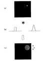
図4(a)は、特定の画素がゼロで無い輝度を有し、他の画素がゼロの輝度を有する画像(点像)を模式的に示す図である。図4(b)は、焦点外れによるぼやけの点拡がり関数PSFを示す図であり、図4(b)の左側のグラフはピルボックス関数の一例を示し、右側のグラフはガウス関数の一例を示している。図4(c)は、図4(a)の画像に対して、焦点外れによるぼやけの点拡がり関数PSFの畳み込みを行うことにより得られる画像を示す図である。図4(c)の画像では、焦点外れによるぼやけが生じている。このぼやけは、手振れによるぼやけとは異なり、中心から対称に広がる輝度の分布を有している。ぼやけの程度は、厳密には点拡がり関数PSFによって規定されるが、概略的には、点像の広がりの大きさ(直径または半径)によって評価され得る。 FIG. 4A is a diagram schematically showing an image (point image) in which a specific pixel has a non-zero luminance and other pixels have a zero luminance. FIG. 4B is a diagram showing a point spread function PSF of blur due to defocusing, the left graph of FIG. 4B shows an example of a pillbox function, and the right graph shows an example of a Gaussian function. ing. FIG. 4C is a diagram illustrating an image obtained by performing convolution of the point spread function PSF of blur due to defocusing on the image of FIG. In the image of FIG. 4C, blurring due to defocusing occurs. Unlike the blur caused by camera shake, this blur has a luminance distribution that spreads symmetrically from the center. The degree of blurring is strictly defined by the point spread function PSF, but can be roughly evaluated by the size (diameter or radius) of the point image spread.
次に、焦点外れのぼやけについて詳細を説明する。 Next, details of defocus blur will be described.
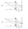
図5(a)は、結像レンズによる焦点が合っている場合の光線図であり、図5(b)は、焦点が外れている場合の光線図である。図5(a)の例では、レンズから距離Aだけ離れた点Sが、レンズから距離Bだけ離れた撮像面上に点sの像を形成している。 FIG. 5A is a ray diagram when the imaging lens is in focus, and FIG. 5B is a ray diagram when the image is out of focus. In the example of FIG. 5A, the point S that is separated from the lens by the distance A forms an image of the point s on the imaging surface that is separated from the lens by the distance B.
図5(a)では、距離Bはレンズの焦点距離Cに一致している。一方、図5(b)では、距離Bはレンズの焦点距離Cに一致していないため、撮像面上における像はぼやけており、その輝度分布は直径bの広がりを有している。 In FIG. 5A, the distance B matches the focal length C of the lens. On the other hand, in FIG. 5B, since the distance B does not coincide with the focal length C of the lens, the image on the imaging surface is blurred, and the luminance distribution has a diameter b.
ぼやけの広がりの大きさ(直径b)は、以下の式10で近似的に示すことができる。
ここで、γはレンズの開口径である。 Here, γ is the aperture diameter of the lens.
式10からわかるように、bの大きさは、撮像時におけるレンズと被写体との距離A、レンズと撮像面との距離B、焦点距離C、レンズ開口径γに依存して変化し得る。 As can be seen from Equation 10, the size of b can vary depending on the distance A between the lens and the object at the time of imaging, the distance B between the lens and the imaging surface, the focal length C, and the lens aperture diameter γ.
撮像面上における点像の輝度分布は、焦点外れのぼやけを示す点拡がり関数PSFに応じて、例えばピルボックス関数またはガウス関数で近似的に表現することができる。 The luminance distribution of the point image on the imaging surface can be approximately expressed by, for example, a pillbox function or a Gaussian function according to the point spread function PSF indicating blurring out of focus.
この点拡がり関数PSFをピルボックス関数で近似した場合、PSFすなわちf2(x,y)は、以下の式11で表される。
ここで、circ(X)は、Xの絶対値が1/2以下のときに1の値を持ち、それ以外は0の値を持つ円形関数である。一方、焦点外れによるぼやけの点広がり関数PSFをガウス関数で近似した場合、f2(x,y)は、以下の式12で表される。
σは、ガウス分布の標準偏差であり、例えば、点像のぼやけの広がり(半径b/2)程度の値と置くことができる。このように、焦点外れによるぼやけのPSF、すなわちf2(x,y)は、図5(b)に示す撮像面上の像から測定によって求めることができる。なお、点拡がり関数PSFは、結像レンズの収差が小さいほど、ピルボックス関数で良く近似することができる。σ is a standard deviation of the Gaussian distribution, and can be set to a value that is about the extent of blurring of the point image (radius b / 2), for example. Thus, the blurred PSF due to defocusing, that is, f2 (x, y) can be obtained by measurement from the image on the imaging surface shown in FIG. The point spread function PSF can be approximated by a pillbox function better as the aberration of the imaging lens is smaller.
ピルボックス関数のフーリエ変換は0次の第1種ベッセル関数J0であり、ガウス関数のフーリエ変換はガウス関数である。このような関数F2(u,v)は、いずれも、(u,v)=(0,0)で最大となり、低周波数領域で相対的に大きな値を有している。また、ベッセル関数は特定の周波数でゼロとなるが、ガウス関数はゼロにならない。このため、低周波数領域において、F1(u,v)およびF2(u,v)が同一周波数でゼロにならず、F1(u,v)+F2(u,v)はゼロ以外の値を有している。The Fourier transform of the pillbox function is a zeroth-order first-type Bessel function J0 , and the Fourier transform of the Gaussian function is a Gaussian function. Such a function F2 (u, v) is maximum when (u, v) = (0, 0), and has a relatively large value in the low frequency region. In addition, the Bessel function is zero at a specific frequency, but the Gaussian function is not zero. Therefore, in the low frequency region, F1 (u, v) and F2 (u, v) are not zero at the same frequency, and F1 (u, v) + F2 (u, v) is not zero. Has a value.
以上の説明から明らかなように、本発明によれば、少なくとも低周波数領域で式9の分母がゼロにならないようできる。その結果、画像の「平坦部」におけるリンギングノイズを低減し、それによって、リンギングが目立たない高質な画像の復元を実現できる。 As is apparent from the above description, according to the present invention, the denominator of Equation 9 can be prevented from becoming zero at least in the low frequency region. As a result, ringing noise in the “flat portion” of the image can be reduced, thereby realizing high-quality image restoration in which ringing is not noticeable.
図6は、本発明による撮像素子における撮像部の構成を模式的に示す図である。本実施形態では、被写体からの光が分光部60により、2つに分離される。分光部60は、レンズと、レンズを透過した光を2方向に分離する光スプリッタとを備えている。分光部60を透過した光の一方は第1撮像素子10Aに入射し、他方は第2撮像素子10Bに入射する。撮像素子10Aおよび撮像素子10Bの一方は、レンズの焦点が合う位置に配置され、他方はレンズの焦点が外れる位置に配置される。このような配置は、例えば、レンズから第1撮像素子10Aまでの光学的な距離と、レンズから第2撮像素子10Bまでの光学的な距離とを異なる値に設定することにより実現される。光学的な距離を異ならせる典型的な配置は、物理的な距離を変化させることで実現されるが、本発明は、そのような場合に限定されない。 FIG. 6 is a diagram schematically showing the configuration of the imaging unit in the imaging device according to the present invention. In the present embodiment, the light from the subject is separated into two by the
図7(a)は、レンズ20を透過した光を光スプリッタ40で2方向に分離する構成例を示す図である。この構成例では、レンズ20から第1撮像素子10Aまでの距離が、レンズ20から第2撮像素子10Bまでの距離よりも長い。また、図7(b)は、他の構成例を示す図である。この構成例では、レンズ20から第1撮像素子10Aまでの距離と、レンズ20から第2撮像素子10Bまでの距離とは等しい。しかし、レンズ20と第1撮像素子10Aとの間に空気の屈折率とは異なる屈折率を有する透明材料からなる光学素子45が挿入されている。このような光学素子45の介在により、レンズ20から第1撮像素子10Aまでの光学的な距離と、レンズ20から第2撮像素子10Bまでの光学的な距離とが異なるため、第1撮像素子10Aと第2撮像素子10Bとの間で合焦状態を変化させることができる。光路上に挿入する光学素子は、撮像素子10A、10Bの撮像面上における合焦状態に差異を形成できればよく、凹レンズ形状、凸レンズ形状、もしくは平板形状、または、これらを複合した形状のいずれを有していても良い。 FIG. 7A is a diagram illustrating a configuration example in which the light transmitted through the
図7(c)は、更に他の構成例を示す図である。この構成例では、光スプリッタ40で2方向に分離された光が、それぞれ、異なるレンズ20A、20Bによって集光される。レンズ20A、20Bが同一の焦点距離を有する場合、レンズ20Aから第1撮像素子10Aまでの距離とレンズ20Bから第2撮像素子10Bまでの距離が異なるように構成される。なお、レンズ20Aとレンズ20Bとの間で焦点距離などのレンズ特性を変化させても良い。このような構成を採用する場合でも、予め種々の撮影条件の下で意図的に第2撮像素子10Bで発生させる焦点外れのぼやけを規定する点拡がり関数を求めておくことができる。 FIG. 7C is a diagram showing still another configuration example. In this configuration example, light separated in two directions by the
このように、本発明の好ましい実施形態によれば、2つの撮像素子10A、10Bの一方からは焦点の合った画像の信号を取得し、他方からは焦点が外れた画像の信号を取得する。そして、それらの信号を合算することにより、劣化画像の信号を生成する。こうして得られた劣化画像について、復元処理を実行すれば、リンギングの発生を抑制することが可能なる。 Thus, according to a preferred embodiment of the present invention, a signal of an in-focus image is acquired from one of the two
以下、本発明による撮像装置の実施形態を説明する。 Hereinafter, embodiments of an imaging apparatus according to the present invention will be described.
図8は、本実施形態における撮像装置の概略構成を示すブロック図である。 FIG. 8 is a block diagram illustrating a schematic configuration of the imaging apparatus according to the present embodiment.
本実施形態の撮像装置は、デジタル式の電子カメラであるが、これに限定されない。本実施形態の撮像装置は、図8に例示するように、撮像部100と、各種信号処理を行う信号処理部200と、撮像によって取得した画像を表示する撮像表示部300と、画像のデータを記録する記録部400と、各部を制御するシステム制御部500とを備える。本実施形態の撮像装置が公知の撮像装置と異なる主な点は、撮像部100の構成および信号処理部200の動作にある。したがって、以下の説明では、主として撮像部100および信号処理部200を詳しく説明する。 The imaging apparatus of the present embodiment is a digital electronic camera, but is not limited to this. As illustrated in FIG. 8, the imaging apparatus according to the present embodiment includes an
本実施形態における撮像部100は、撮影レンズ20と、絞り機能を有するシャッタ15と、撮影レンズ20を透過した光を2つに分離する光スプリッタ40と、光スプリッタ40によって分離された光を受け取る2つの撮像素子10A、10Bとを有している。撮像素子10A、10Bは、撮像面上に配列された複数の光感知セル(フォトダイオード)を備えている。撮像素子10A、10Bの典型例は、CCDまたはCMOSセンサである。撮影レンズ20は、公知の構成を有しており、現実には複数のレンズから構成されたレンズユニットであり得る。シャッタ15および撮影レンズ20は、不図示の機構によって駆動され、光学ズーミング、自動露光(AE:Auto Exposure),オートフォーカス(AF:Auto Focus)に必要な動作が実行される。 The
更に、撮像部100は、撮像素子10A、10Bを駆動する撮像素子駆動部30を備えている。撮像素子駆動部30は、例えばCCDドライバなどの半導体集積回路から構成され得る。撮像素子駆動部30は、撮像素子10A、10Bを駆動することにより、撮像素子10A、10Bからアナログ信号(光電変換信号)を読み出してデジタル信号に変換する。本実施形態によれば、光スプリッタ40の働きにより、同一被写体の像が撮像素子10A、10Bによって同時に取得され得るが、一方の撮像素子10Aでは焦点のあった状態で撮像が行われ、他方の撮像素子10Bでは焦点外れのある状態で撮像が行われる。このため、撮像素子駆動部30は、2つの撮像素子10A、10Bの両方から光電変換信号を読み出し、それらを加算することにより得られた画像信号を生成する。このような画像信号によって表現される画像は、意図的に形成された焦点外れによるぼやけを含む劣化画像である。信号処理部200には、この劣化画像のデータが入力される。 Furthermore, the
なお、本実施形態では、撮影レンズ20から第1撮像素子10Aまでの実際の距離と、撮影レンズ20から第2撮像素子10Bまでの実際の距離との差異が固定されており、第1撮像素子10Aで焦点が合っているときに、第2撮像素子10Bで生じる焦点外れによるぼやけを規定する点拡がり関数は既知である。この点拡がり関数は、撮影レンズ20の焦点距離や絞りの開口径などの撮影パラメータに応じて既存のテーブルなどから求められ得る。 In the present embodiment, the difference between the actual distance from the
本実施形態における信号処理部200は、画像処理部(イメージプロセッサ)220、メモリ240、およびインターフェース(IF)部260を備えている。信号処理部200は、液晶表示パネルなどの表示部300、および、メモリカードなどの記録媒体400に接続されている。 The
画像処理部220は、色調補正、解像度変更、データ圧縮などの各種信号処理を行うほか、本発明による劣化画像の復元処理を実行する。画像処理部220は、公知のデジタル信号処理プロセッサ(DSP)などのハードウェアと、画像処理を実行するためのソフトウェアとの組合せによって好適に実現される。メモリ240は、DRAMなどによって構成される。このメモリ240は、撮像部100から得られた画像データを記録するとともに、画像処理部220によって各種の画像処理を受けた画像データや、圧縮された画像データを一時的に記録する。画像データは、アナログ信号に変換された後、表示部300によって表示され、あるいは、デジタル信号のままインターフェース部260を介して記録媒体400に記録される。画像データは、不図示の通信装置を介して、無線または有線で他の装置(不図示)に送信されてもよい。 The
なお、使用者が被写体にカメラを向けているときf、表示部300に第1撮像素子10Aによって取得される画像が表示されることが好ましい。これにより、使用者は焦点外れによるぼやけの無い画像を見ながら撮影を行うことができる。 Note that it is preferable that an image acquired by the first imaging element 10 </ b> A is displayed on the
上記の構成要素は、不図示の中央演算処理ユニット(CPU)およびフラッシュメモリを含むシステム制御部500によって制御される。なお、本実施形態の撮像装置は、光学ファインダ、電源(電池)、フラッシュライトなどの公知の構成要素を備え得るが、それらの説明は本発明の理解に特に必要でないため省略する。 The above-described components are controlled by a
上述したように、本実施形態の撮像素子100によれば、焦点の合った像を撮像素子10Aの撮像面上に形成するとともに、焦点を意図的に外した像を撮像素子10Bに形成することができる。なお、撮像素子10Aの撮像面上に焦点の合った像は、通常のオートフォーカス技術により、容易に形成される。 As described above, according to the
意図的に焦点を外した状態で撮像を行うとき、露光中の手振れによって画像にブレ(motion blur)が発生したと仮定する。このようにして得られた画像のぼやけの点拡がり関数PSFは、前述したように、f1(x,y)およびf2(x,y)を足し合わせたものである。When imaging is performed with the focus out of focus, it is assumed that motion blur occurs in the image due to camera shake during exposure. The blurring point spread function PSF of the image obtained in this way is the sum of f1 (x, y) and f2 (x, y) as described above.
次に、焦点外れによるぼやけのPSF、すなわち、f2(x,y)の求め方を説明する。Next, a method for obtaining the PSF of blur due to defocus, that is, f2 (x, y) will be described.
まず、図9(a)に示すように背景が黒く、小さな輝点を中心に有するパターンを撮影する。このとき、第1撮像素子10Aでは、図9(b)に示すように、焦点の合った像が形成される。一方、第2撮像素子10Bでは、図9(c)に示すように、焦点が外れた像が形成される。 First, as shown in FIG. 9A, a pattern having a black background and having a small bright spot at the center is photographed. At this time, in the
焦点外れによるぼやけのPSFを、円柱状に点が広がるピルボックス関数で近似する場合、撮像面における点像の広がり(直径b)が円柱の直径に相当する。このため、点像の広がりを測定すれば、焦点外れのぼやけを示すPSF(ピルボックス関数)を決定することができる。点像の広がりは、撮像面における画素数で表現することができ、撮像素子によって容易に検出することができる。 When the PSF that is blurred due to defocusing is approximated by a pillbox function in which points spread in a cylindrical shape, the spread (diameter b) of the point image on the imaging surface corresponds to the diameter of the column. For this reason, if the spread of the point image is measured, a PSF (pill box function) indicating blur of defocus can be determined. The spread of the point image can be expressed by the number of pixels on the imaging surface, and can be easily detected by the imaging device.
なお、レンズの形状によっては、収差などにより、点像の面内輝度がガウス分布を示す場合がある。そのような場合は、焦点外れによるぼやけのPSFをガウス関数で近似することが好ましい。撮像面上に広がった点像の輝度分布は、撮像素子によって測定されるため、その輝度分布から、対応するガウス関数のσを決定することができる。 Depending on the shape of the lens, the in-plane luminance of the point image may exhibit a Gaussian distribution due to aberrations or the like. In such a case, it is preferable to approximate the PSF of blur due to defocusing with a Gaussian function. Since the luminance distribution of the point image spread on the imaging surface is measured by the imaging device, the corresponding Gaussian function σ can be determined from the luminance distribution.
このようにして焦点外れのぼやけを規定するPSF(f2(x,y))が予め測定によって決定され、撮像装置が内蔵するメモリのテーブルなどに格納される。このPSF(f2(x,y))は、撮影レンズ20の焦点距離や絞りの開口径などの撮影パラメータにも依存する。すなわち、被写体までの距離が変わると撮影レンズ20の焦点距離が変化し、また、開口径が変わると被写界深度が変化する。したがって、撮影パラメータの値の可能な組み言わせに関連付けて、多数のPSF(f2(x,y))を測定し、メモリに記録させておくことが好ましい。そうすることにより、現実の撮影時において、撮影パラメータに応じた焦点外れのPSF(f2(x,y))を求めることができる。In this way, the PSF (f2 (x, y)) that defines the out-of-focus blur is determined in advance by measurement and stored in a memory table or the like built in the imaging apparatus. This PSF (f2 (x, y)) also depends on photographing parameters such as the focal length of the photographing
次に、ユーザが本実施形態の撮像装置によって撮像を行うときの動作を説明する。 Next, an operation when the user performs imaging with the imaging apparatus of the present embodiment will be described.
まず、通常のデジタルカメラによる撮像を行うように、ユーザは被写体に撮像装置を向け、シャッタボタンを半押しすると、第1撮像素子10Aで焦点の合った像が形成されるように、自動焦点動作により被写体に焦点が合う。このとき、第1撮像素子10Aの撮像面には焦点の合った像が形成されるが、第2撮像素子10Bの撮像面には焦点外れによってぼやけの発生した像が形成される。 First, as with a normal digital camera, when the user points the imaging device at a subject and presses the shutter button halfway, an automatic focusing operation is performed so that an in-focus image is formed by the
次に、ユーザがシャッタボタンを深く押し込むと、撮像素子10A、10Bの「露光」が開始される。露光中にユーザによって撮像装置が不安定に動いた場合、撮像素子10A、10Bの撮像面上を像が移動するため、いずれの像にも手振れによるぼやけが加算されることになる。 Next, when the user presses the shutter button deeply, “exposure” of the
信号処理部200は、撮像部100によって取得された信号を受け取る。こうして得られた画像は、式7の左辺にあるi(x、y)で表される劣化画像である。本実施形態におけるi(x、y)は、撮像素子10A、10Bから出力される画像信号を加算することにより得られる。撮像素子10A、10Bから出力は、単純に加算されてもよいが、一方の出力と他方の出力とに異なる重み付けをした上で加算されてもよい。このような重み付けは、撮像素子10A、10Bのサイズ、解像度、画素数、および開口率の少なくとも何れかが異なる場合や、撮像素子10A、10Bに入射する光の強さが異なる場合には、好適に実行され得る。 The
信号処理部200における画像処理部220は、i(x、y)からs(x,y)を復元するための処理を行う。この復元処理のアルゴリズムは、特に限定されず、公知の画像復元処理のいずれであってもよい。 The
以下、図10および図11を参照しながら、本実施形態で実行し得る復元処理の一例を説明する。図10は、図8に示す画像処理部220の構成例を示すブロックであり、図11は、復元処理の例を示すフローチャートである。 Hereinafter, an example of restoration processing that can be executed in the present embodiment will be described with reference to FIGS. 10 and 11. FIG. 10 is a block diagram illustrating a configuration example of the
まず、図10を参照する。図10に示す画像処理部220は、初期PSF設定部222、画像復元部224、PSF設定部226、およびパラメータ更新部228を備え、劣化画像の入力を得て復元結果を出力する。初期PSF推定部222は、画像復元部224による処理に必要な初期PSFを設定する。この初期PSFは、カメラの運動(軌跡)をジャイロセンサなどのセンサによって検出し、その軌跡に基づいて決定しても良いし、使用者が手動で入力してもよい。なお、画像処理に要する時間を短縮するという観点から、初期PSFは真のPSFに近いことが好ましい。このため、センサによって検出したカメラの軌跡から定まるPSFに対して焦点外れのPSFを加算したPSFを初期PSFに設定することが好ましい。 First, referring to FIG. The
画像復元部224は、初期PSFに基づいて劣化画像から復元画像を得る。PSF推定部226は、劣化画像、および、画像復元部224で得た復元画像に基づいてPSFの推定を行う。パラメータ更新部228は、PSF推定部226によって得られたPSF(推定されたPSF)で初期PSF(前回の画像復元に用いたPSF)を更新する。更新されたPSFは、画像復元部224に与えられ、上記の処理が繰り返し実行される。 The
図10に示す構成は、画像処理部220の機能ブロックの例であり、画像処理部220は、他の機能ブロックに分割され得る。画像処理部220は、例えば公知のハードウェアに画像処理のソフトウェアを組み込むことによっても好適に実現される。 The configuration illustrated in FIG. 10 is an example of functional blocks of the
次に、図11を参照しながら復元処理の概略手順を説明する。 Next, a schematic procedure of the restoration process will be described with reference to FIG.
まず、ステップS1において、劣化画像の読み出しを行う。具体的には、復元処理のベースとなる劣化画像を、画像処理部220が図8のメモリ240から取得する。劣化画像は、図8の撮像部100によって取得された画像であり、本実施形態では、意図的な焦点外れによるぼやけが付与されている。一般には、使用者による撮像部100の振れ(運動)により、手振れによるぼやけ(ブレ)も劣化画像に付与される。 First, in step S1, a degraded image is read out. Specifically, the
ステップS2において、初期PSF設定部222は初期PSFを設定する。ステップS3において、画像復元部224は、ステップS1で取得した劣化画像とステップS2で設定した初期PSFとを用いて画像復元処理を実行する。この画像復元処理は、図10の画像復元部224において、公知の復元アルゴリズムによって実行することができる。画像復元部224は、得られた復元画像をいったんメモリ240に記録する。ステップS4では、PSF推定部226が復元画像からPSFの推定を行い、パラメータ更新部228が、推定されたPSFによって前のPSFを更新する。 In step S2, the initial
ステップS5において、更新前後のPSF、および、更新前後の復元画像の変化が所定の閾値よりも小さいか否かを判定し、小さい場合は処理が収束したと判断する。ステップS6では、復元結果をメモリ240に格納する。 In step S5, it is determined whether or not the PSF before and after the update and the change in the restored image before and after the update are smaller than a predetermined threshold. If the change is small, it is determined that the process has converged. In step S6, the restoration result is stored in the
以下、ステップS2〜S3で行うPSF推定および画像復元の詳細を説明する。 Details of PSF estimation and image restoration performed in steps S2 to S3 will be described below.
ここでは、非特許文献1に開示されている信号処理法による場合を説明する。非特許文献1の信号処理法による場合、まず初期PSFを与える必要がある。この初期PSFは、手動あるいは、手振れ検知装置(ジャイロセンサなどの外部デバイス)によって与えられる。この初期PSFに基づいて、第1の画像復元が行われる。この段階のPSFは、必ずしも真のPSF(正解)に一致しているものではないが、復元される結果は、劣化画像に比べると原画像に近づいたものとなる。 Here, the case of the signal processing method disclosed in Non-Patent Document 1 will be described. In the case of the signal processing method of Non-Patent Document 1, it is necessary to first provide an initial PSF. This initial PSF is given manually or by a camera shake detection device (external device such as a gyro sensor). A first image restoration is performed based on the initial PSF. The PSF at this stage does not necessarily match the true PSF (correct answer), but the restored result is closer to the original image than the degraded image.
続いて、第1の画像復元の結果である第1の復元画像からPSFの推定を行う。第1の復元画像が劣化画像よりも原画像に近づいているため、推定されるPSFは正解に近づく。ここで推定したPSFを用いて、すなわち、初期PSFを次のPSFで更新して、第2の画像復元を行う。この処理をPSFの変化、および、画像復元結果の変化がなくなるまで繰り返し行うことにより、PSF推定と画像復元を同時に行う。 Subsequently, the PSF is estimated from the first restored image that is the result of the first image restoration. Since the first restored image is closer to the original image than the degraded image, the estimated PSF approaches the correct answer. Using the PSF estimated here, that is, the initial PSF is updated with the next PSF, the second image restoration is performed. By repeating this process until there is no change in PSF and no change in image restoration result, PSF estimation and image restoration are performed simultaneously.
以下、画像復元処理の更に具体的な方法を述べる。 Hereinafter, a more specific method of image restoration processing will be described.
まず、画像復元に先立って、初期PSF設定部222により、初期PSFを与える。非特許文献1に開示されている方法では、初期PSFを手動で与えているが、本実施形態では、ジャイロセンサによって取得した動き情報に基づいてPSFの初期値を設定する。 First, prior to image restoration, the initial PSF is given by the initial
画像復元部224は、与えられたPSF(最初は初期値、次からは更新値)と劣化画像により、画像の復元を行う。この処理に使用する評価式ELを式13に示す。
ここで、Iは劣化画像、Lはブレおよびぼやけのない画像L、fは点拡がり関数PSFである。変数wk、λ1、λ2は手動で設定される「重み」である。Θは、どのような微分を画像に施すかを規定する演算子のセットである。具体的には、0回微分、1回微分(x、y方向それぞれ)、2回微分(x方向に二回、y方向に二回、xとy方向に1回ずつ)の合計6個の微分パラメータを持つ。d*は、微分演算子である。d*を用いてΘを表現すると、Θ={d0、dx、dy、dxx、dxy、dyy}となる。d*により、輝度情報とエッジ情報の両方を用いた処理を行うことが可能になり、輝度だけでは得られない情報も得ることができる。Mは、2次元のマスクであり、画像中の平坦な領域、すなわち局所的なスムーズな領域(Ω)に含まれる画素では「1」の要素、それ以外の画素では「0」の要素を有している。||・||pは、pノルム演算子である。Φ(x)は、自然に観察される画像中の輝度勾配xとその分布密度(対数表示)との関係を近似的に示す関数である。Here, I is a degraded image, L is an image L without blur and blur, and f is a point spread function PSF. The variables wk, λ1, and λ2 are “weights” set manually. Θ is a set of operators that define what differentiation is applied to the image. Specifically, there are a total of 6 derivatives: 0 differentiation, 1 differentiation (x and y directions respectively), 2 differentiation (twice in the x direction, twice in the y direction, and once in the x and y directions). Has derivative parameters. d * is a differential operator. When Θ is expressed using d *, Θ = {d0 , dx ,dy , dxx , dxy , dyy }. With d *, it is possible to perform processing using both luminance information and edge information, and information that cannot be obtained only by luminance can be obtained. M is a two-dimensional mask, and has a “1” element in a pixel included in a flat area in an image, that is, a local smooth area (Ω), and a “0” element in other pixels. doing. || · ||p is a p-norm operator. Φ (x) is a function that approximately represents the relationship between the luminance gradient x in a naturally observed image and its distribution density (logarithmic display).
式13の右辺における第1項は、復元画像Lと点拡がり関数fとの畳み込みを行って得られる画像と劣化画像Iとの差(距離)を示す項である。画像に対して6個の微分パラメータによる演算を施すことにより、輝度以外の情報に基づいて画像の近似度を評価できる。 The first term on the right side of Equation 13 is a term indicating the difference (distance) between the image obtained by convolution of the restored image L and the point spread function f and the degraded image I. By performing an operation with six differential parameters on the image, the degree of approximation of the image can be evaluated based on information other than luminance.
式13の右辺における第2項は、画像内の輝度勾配の性質(「heavy tail」と呼ばれる)を示す項である。Φ(dxL)、Φ(dyL)は、復元画像の輝度勾配をヒストグラム化したときに、勾配が0付近に出現確率の急激なピークが現れ、勾配が大きくなるにつれ出現確率が小さくなるという、統計的性質を持つ。第2項では、x方向の勾配とy方向の勾配のそれぞれに対して、上記の統計的性質を示す分布からの距離を算出している。この統計的性質は、非特許文献3〜5に開示されている方法でも利用されている。The second term on the right side of Equation 13 is a term indicating the property of the luminance gradient in the image (called “heavy tail”). When Φ (dx L) and Φ (dy L) are histograms of the luminance gradient of the restored image, a sharp peak of the appearance probability appears near the gradient, and the appearance probability decreases as the gradient increases. It has a statistical property. In the second term, the distance from the distribution showing the above statistical properties is calculated for each of the gradient in the x direction and the gradient in the y direction. This statistical property is also used in the methods disclosed in Non-Patent Documents 3 to 5.
式13の右辺における第3項は、マスクMと微分劣化画像と微分復元画像を用いて、平坦度の評価を行う項である。平坦な領域では、劣化画像と復元画像との間で輝度の勾配値が近い値を持つ。そのため、x、y方向の勾配値の誤差を評価値として用いる。 The third term on the right side of Equation 13 is a term for evaluating the flatness using the mask M, the differentially degraded image, and the differentially restored image. In the flat region, the gradient value of the luminance is close between the degraded image and the restored image. Therefore, an error in gradient values in the x and y directions is used as an evaluation value.
式13の右辺を最小化するLを求めることにより、復元画像Lを求めることができる(Lの最適化)。Lの最適化の具体的な計算方法は、非特許文献1に開示されている。 By obtaining L that minimizes the right side of Equation 13, the restored image L can be obtained (optimization of L). A specific calculation method for optimizing L is disclosed in Non-Patent Document 1.
次に、復元画像Lが得られた後に行う、PSF推定部226による処理を詳しく説明する。 Next, the process performed by the
PSF推定は、画像復元部224で得られた復元画像Lと劣化画像Iとを用いて点拡がり関数fを推定する問題である。fは、以下の式14の右辺を最小化するようにfを決定することにより、点拡がり関数fを求めることができる(fの最適化)。
式14の右辺における第1項は、式13の右辺における第1項に相当し、復元画像Lと点拡がり関数fとの畳み込みが劣化画像Iに近いか否かを示す評価基準を与える。式14の右辺における第2項は、点拡がり関数fの1ノルムである。第2項は、スパースコーディングと呼ばれる考え方に基づく項である。点拡がり関数fの行例における大部分の要素が0(動きがない)であることから、この最適化項が用いられる。本実施形態では、非特許文献1と同様に「interior point method」による最適化を行い、全体最適化を実現できる。 The first term on the right side of Equation 14 corresponds to the first term on the right side of Equation 13, and gives an evaluation criterion indicating whether or not the convolution of the restored image L and the point spread function f is close to the degraded image I. The second term on the right side of Equation 14 is the 1 norm of the point spread function f. The second term is a term based on a concept called sparse coding. This optimization term is used because most elements in the line example of the point spread function f are 0 (no movement). In the present embodiment, optimization by “interior point method” is performed in the same manner as in Non-Patent Document 1, and overall optimization can be realized.
なお、画像復元の手順は、上記の例に限定されない。例えば、リチャードソンルーシ(LR)法やウィーナフィルタ法を用いても良い。 Note that the image restoration procedure is not limited to the above example. For example, the Richardson Lucy (LR) method or the Wiener filter method may be used.
本実施形態における画像復元で重要な点は、意図的に与える焦点はずれによるぼやけの点拡がり関数PSFを既知とすることにある。動きの情報は、ジャイロセンサによって取得できるため、焦点はずれが生じても、その点拡がり関数PSFが既知であれば、LR法などの従来から知られている簡便な手法を適用して画像の復元を実現することできる。このため、信号処理にかかる負担を軽減させることが可能になる。 An important point in the image restoration in the present embodiment is to make the point spread function PSF of blurring due to intentional defocusing known. Since the motion information can be acquired by the gyro sensor, if the point spread function PSF is known even if defocusing occurs, an image restoration can be performed by applying a conventionally known simple method such as the LR method. Can be realized. For this reason, it becomes possible to reduce the burden concerning signal processing.
本実施形態では、手振れによるぼやけを規定するPSFをも推定の対象とするブラインド・デコンボリューションによって画像の復元を行ったが、本発明はこれに限定されない。撮像装置に取り付けられたジャイロセンサによって「手振れ軌跡」を高い精度で検出できれば、検出した手振れ軌跡に基づいて得られたPSFを画像復元処理のための単なる初期値として用いるだけではなく、手触れによるぼやけを規定する最終的なPSFとして用いても良い。この場合、焦点外れによるぼやけを規定するPSFも既知であり、ぼやけの点拡がり関数がすべて既知となるため、推定すべきは復元画像のみとなる。 In the present embodiment, the image restoration is performed by blind deconvolution in which the PSF that defines blur due to camera shake is also an object of estimation, but the present invention is not limited to this. If the “hand shake trajectory” can be detected with high accuracy by the gyro sensor attached to the image pickup apparatus, the PSF obtained based on the detected hand shake trajectory is not only used as a mere initial value for image restoration processing, but also by hand touch. It may be used as a final PSF that defines blur. In this case, the PSF that defines blur due to defocusing is also known, and all the point spread functions of blur are known, so that only the restored image should be estimated.
このように本実施形態によれば、復元方法の種類によらず、劣化画像に意図的な焦点外れによるぼやけが付加されるため、手振れによるぼやけ(ブレ)で劣化した画像を復元した場合でも、画像の平坦部でリンギングが目立たないという効果が得られる。 As described above, according to the present embodiment, since the blur due to intentional defocusing is added to the deteriorated image regardless of the type of the restoration method, even when the image deteriorated due to the blur (blur) due to camera shake is restored, The effect that ringing is not conspicuous in the flat part of the image is obtained.
上記の実施形態では、第1撮像素子10Aに焦点が合っているとき、第2撮像素子10Bに生じる焦点外れのぼやけを規定する点拡がり関数が既知である。しかし、本発明は、このような場合に限定されない。焦点外れのぼやけを既定する点拡がり関数が既知の場合は、精度よくブレとボケの復元が可能になる。 In the above-described embodiment, when the
なお、2つの撮像素子10A、10Bで取得された画像のどちらにも焦点外れによるぼやけが発生していることが有り得る。このような場合でも、合成された劣化画像のぼやけ全体を規定するPSFを推定して復元画像を得ることは可能である。2つの撮像素子10A、10Bから得られる合成画像でピントが合っている必要がないため、ピント調整が不要であるという利点がある。例えば、奥行きのある風景を撮影対象とする場合、被写体に必ずしも焦点が合うわけではない。このような場合でも、本発明は有効である。本発明の好ましい実施形態において、2つの撮像素子10A、10Bの両方で焦点外れが生じる場合、各々の焦点外れによるぼやけを規定する点拡がり関数は相互に異なる関数となる。この場合、焦点はずれによるぼやけを規定する2つの点拡がり関数のフーリエ変換がともに特定の空間周波数で零になることはない。このため、2つの撮像素子10A、10Bの両方で焦点外れを生じさせることにより、リンギング抑制の効果が更に高められる。 Note that it is possible that blur due to defocusing has occurred in either of the images acquired by the two
第1撮像素子10Aと第2撮像素子10Bとは、同じ解像度を有する必要は無い。例えば、片方の解像度が小さい場合は、超解像技術(例えば魏,田中,奥富; 実時間動画像超解像処理システム第15回画像センシングシンポジウム(SSII2009)講演論文集, pp.DS2-01-1-1, 2009)により、一方の画像の解像度を高めることができる。異なる解像度の画像を同一解像度に復元した後に、上記の処理により、ブレとボケを低減するための画像復元を行ってもよい。 The
また、本発明が備える撮像素子の個数は、2個に限定されず、3個以上であってもよい。 In addition, the number of image sensors provided in the present invention is not limited to two, and may be three or more.
本発明の撮像装置は、平坦部でリンギングの少ない画像を復元できるため、電子スチルカメラなどとして利用可能である。 The image pickup apparatus of the present invention can be used as an electronic still camera or the like because an image with little ringing can be restored at a flat portion.
10A 第1撮像素子
10B 第2撮像素子
15 絞り機能を有するシャッタ
20 撮影レンズ
30 撮像素子駆動部
40 光スプリッタ
45 光学素子
60 分光部
100 撮像部
200 信号処理部
220 画像処理部
222 初期PSF設定部
224 画像復元部
226 PSF推定部
228 パラメータ更新部
240 メモリ
260 インターフェース(IF)
300 表示部
400 記録媒体
500 システム制御部10A
300
Claims (9)
Translated fromJapanese前記第1撮像素子の撮像面上に焦点が合っている第1の像を形成し、かつ、前記第2撮像素子の撮像面上に焦点が外れた第2の像を形成し得る光学系と、
前記第1撮像素子および前記第2撮像素子から得られる信号を処理する画像処理部と、を備え、
前記画像処理部は、
前記第1撮像素子および前記第2撮像素子の各撮像面の座標を(x、y)とするとき、
前記第1撮像素子および第2撮像素子によって取得された画像を加算して画像i(x、y)を得て、前記画像i(x、y)から、手振れによるぼやけおよび焦点外れによるぼやけを減少させた復元画像を生成する、撮像装置。A first image sensor and a second image sensor;
An optical system capable of forming a focused first image on the imaging surface of the first imaging element and forming an unfocused second image on the imaging surface of the second imaging element; ,
An image processing unit that processes signals obtained from the first image sensor and the second image sensor;
The image processing unit
When the coordinates of each imaging surface of the first imaging device and the second imaging device are (x, y),
The images acquired by the first image sensor and the second image sensor areadded to obtain an image i (x, y) , and blur due to camera shake and blur due to defocus are reduced from theimage i (x, y). An imaging device that generates a restored image.
前記画像処理部は、撮像時における焦点外れによるぼやけを規定する点広がり関数を前記メモリから読み出し、復元画像の生成に用いる、請求項1に記載の撮像装置。A memory for recording a point spread function that defines blur due to defocusing in the second image sensor;
The imaging apparatus according to claim 1, wherein the image processing unit reads a point spread function that defines blur due to defocusing at the time of imaging from the memory, and uses the function to generate a restored image.
結像レンズと、
前記結像レンズを透過した光を2方向に分離する光スプリッタとを有しており、
分離された一方の光を前記第1撮像素子に入射し、かつ、分離された他方の光を前記第2撮像素子に入射する、請求項1または2に記載の撮像装置。The optical system is
An imaging lens;
An optical splitter that separates light transmitted through the imaging lens in two directions;
The imaging apparatus according to claim 1 or 2, wherein one separated light is incident on the first imaging element, and the other separated light is incident on the second imaging element.
入射光を2方向に分離する光スプリッタと、
分離された一方の光を前記第1撮像素子上に集光する第1結像レンズと、
分離された他方の光を前記第2撮像素子上に集光する第2結像レンズと
を有している、請求項1または2に記載の撮像装置。The optical system is
An optical splitter that separates incident light in two directions;
A first imaging lens for condensing one of the separated lights on the first image sensor;
The imaging apparatus according to claim 1, further comprising: a second imaging lens that condenses the separated other light on the second imaging element.
前記第1撮像素子によって取得された画像を前記表示部に表示する、請求項1から4のいずれかに記載の撮像装置。A display unit;
The imaging device according to claim 1, wherein an image acquired by the first imaging element is displayed on the display unit.
前記第1撮像素子および前記第2撮像素子の各撮像面の座標を(x、y)とするとき、
前記光学系により、前記第1撮像素子の撮像面上に焦点が合っている第1の像を形成させるとともに、前記第2撮像素子の撮像面上に焦点が合っていない第2の像を形成させるステップと、
前記画像処理部により、前記第1撮像素子および第2撮像素子によって取得された画像を加算して画像i(x、y)を得て、前記画像i(x、y)から、手振れによるぼやけおよび焦点外れによるぼやけを減少させた復元画像を生成するステップと
を実行するプログラム。The first image sensor, the second image sensor, and the first image focused on the imaging surface of the first image sensor were formed, and the first image sensor was out of focus on the imaging surface of the second image sensor. A program for controlling an operation of an imaging apparatus including an optical system that forms a second image, and an image processing unit that processes a signal obtained from the first imaging element and the second imaging element,
When the coordinates of each imaging surface of the first imaging device and the second imaging device are (x, y),
The optical system forms a first image that is in focus on the imaging surface of the first image sensor and forms a second image that is not in focus on the image surface of the second image sensor. Step to
The image processing unitadds the images acquired by the first image sensor and the second image sensor to obtainan image i (x, y). From the image i (x, y) , blur due to camera shake and Generating a restored image with reduced blur due to defocusing.
前記第1撮像素子および前記第2撮像素子の各撮像面の座標を(x、y)とするとき、
前記光学系により、前記第1撮像素子の撮像面上に焦点が合っている第1の像を形成させるとともに、前記第2撮像素子の撮像面上に焦点が合っていない第2の像を形成させるステップと、
前記画像処理部により、前記第1撮像素子および前記第2撮像素子によって取得された画像を加算して画像i(x、y)を得て、前記画像i(x、y)から、手振れによるぼやけおよび焦点外れによるぼやけを減少させた復元画像を生成するステップと
を含む、画像処理方法。The first image sensor, the second image sensor, and the first image focused on the imaging surface of the first image sensor were formed, and the first image sensor was out of focus on the imaging surface of the second image sensor. An image processing method in an imaging apparatus comprising: an optical system that forms a second image; and an image processing unit that processes a signal obtained from the first imaging element and the second imaging element,
When the coordinates of each imaging surface of the first imaging device and the second imaging device are (x, y),
The optical system forms a first image that is in focus on the imaging surface of the first image sensor and forms a second image that is not in focus on the image surface of the second image sensor. Step to
The image processing unitadds the images acquired by the first image sensor and the second image sensorto obtain an image i (x, y) , and blurs due to camera shake from theimage i (x, y). And a restored image with reduced blur due to defocusing.
前記第1撮像素子および前記第2撮像素子の各撮像面の座標を(x、y)とするとき、
前記光学系により、前記第1撮像素子の撮像面上に焦点が合っていない第1の像を形成させるとともに、前記第2撮像素子の撮像面上にも焦点が合っていない第2の像を形成させるステップと、
前記画像処理部により、前記第1撮像素子および前記第2撮像素子によって取得された画像を加算して画像i(x、y)を得て、前記画像i(x、y)から、手振れによるぼやけおよび焦点外れによるぼやけを減少させた復元画像を生成するステップと
を含む、画像処理方法。The first image sensor, the second image sensor, and the first image focused on the imaging surface of the first image sensor were formed, and the first image sensor was out of focus on the imaging surface of the second image sensor. An image processing method in an imaging apparatus comprising: an optical system that forms a second image; and an image processing unit that processes a signal obtained from the first imaging element and the second imaging element,
When the coordinates of each imaging surface of the first imaging device and the second imaging device are (x, y),
The optical system forms a first image that is not in focus on the imaging surface of the first image sensor, and a second image that is not in focus onthe image surface of the second imagesensor. Forming, and
The image processing unitadds the images acquired by the first image sensor and the second image sensorto obtain an image i (x, y) , and blurs due to camera shake from theimage i (x, y). And a restored image with reduced blur due to defocusing.
Priority Applications (7)
| Application Number | Priority Date | Filing Date | Title |
|---|---|---|---|
| JP2010029039AJP5237978B2 (en) | 2010-02-12 | 2010-02-12 | Imaging apparatus and imaging method, and image processing method for the imaging apparatus |
| US13/260,597US8520081B2 (en) | 2010-02-12 | 2011-01-25 | Imaging device and method, and image processing method for imaging device |
| PCT/JP2011/000380WO2011099239A1 (en) | 2010-02-12 | 2011-01-25 | Imaging device and method, and image processing method for imaging device |
| EP11741990.3AEP2536125B1 (en) | 2010-02-12 | 2011-01-25 | Imaging device and method, and image processing method for imaging device |
| PL11741990TPL2536125T3 (en) | 2010-02-12 | 2011-01-25 | Imaging device and method, and image processing method for imaging device |
| ES11741990TES2779044T3 (en) | 2010-02-12 | 2011-01-25 | Imaging device and procedure, and imaging procedure for imaging device |
| CN201180001619.9ACN102369722B (en) | 2010-02-12 | 2011-01-25 | Camera head and image capture method and the image processing method for described camera head |
Applications Claiming Priority (1)
| Application Number | Priority Date | Filing Date | Title |
|---|---|---|---|
| JP2010029039AJP5237978B2 (en) | 2010-02-12 | 2010-02-12 | Imaging apparatus and imaging method, and image processing method for the imaging apparatus |
Publications (2)
| Publication Number | Publication Date |
|---|---|
| JP2011166588A JP2011166588A (en) | 2011-08-25 |
| JP5237978B2true JP5237978B2 (en) | 2013-07-17 |
Family
ID=44367528
Family Applications (1)
| Application Number | Title | Priority Date | Filing Date |
|---|---|---|---|
| JP2010029039AActiveJP5237978B2 (en) | 2010-02-12 | 2010-02-12 | Imaging apparatus and imaging method, and image processing method for the imaging apparatus |
Country Status (7)
| Country | Link |
|---|---|
| US (1) | US8520081B2 (en) |
| EP (1) | EP2536125B1 (en) |
| JP (1) | JP5237978B2 (en) |
| CN (1) | CN102369722B (en) |
| ES (1) | ES2779044T3 (en) |
| PL (1) | PL2536125T3 (en) |
| WO (1) | WO2011099239A1 (en) |
Families Citing this family (15)
| Publication number | Priority date | Publication date | Assignee | Title |
|---|---|---|---|---|
| CN103314571B (en)* | 2011-11-30 | 2017-09-29 | 松下知识产权经营株式会社 | Cameras and Camera Systems |
| US8929607B2 (en)* | 2011-12-01 | 2015-01-06 | Sony Corporation | System and method for performing depth estimation utilizing defocused pillbox images |
| US20130300912A1 (en)* | 2012-05-14 | 2013-11-14 | Ricoh Innovations, Inc. | Dictionary Learning for Incoherent Sampling |
| US9066002B2 (en)* | 2012-08-29 | 2015-06-23 | Sony Corporation | System and method for utilizing enhanced scene detection in a depth estimation procedure |
| JP5615393B2 (en) | 2013-01-28 | 2014-10-29 | キヤノン株式会社 | Image processing apparatus, imaging apparatus, image processing method, image processing program, and storage medium |
| JP6092049B2 (en)* | 2013-08-28 | 2017-03-08 | 東芝ライフスタイル株式会社 | Imaging system and imaging apparatus |
| US10761014B2 (en)* | 2014-11-04 | 2020-09-01 | Nec Corporation | Method and apparatus for remote sensing using optical orbital angular momentum (OAM)-based spectroscopy for object recognition |
| KR101596203B1 (en)* | 2015-06-16 | 2016-02-22 | 중앙대학교 산학협력단 | Method and apparatus for restoring motion blurred image |
| CN105100456B (en)* | 2015-07-03 | 2019-02-05 | Oppo广东移动通信有限公司 | Method for realizing self-shooting by using external accessory of mobile terminal and mobile terminal |
| US11163169B2 (en)* | 2016-06-07 | 2021-11-02 | Karl Storz Se & Co. Kg | Endoscope and imaging arrangement providing improved depth of field and resolution |
| JP6966934B2 (en)* | 2017-03-29 | 2021-11-17 | パナソニックIpマネジメント株式会社 | Image generator and image pickup device |
| CN107071277B (en)* | 2017-03-31 | 2020-04-03 | 努比亚技术有限公司 | Optical drawing shooting device and method and mobile terminal |
| US12201272B2 (en)* | 2019-03-25 | 2025-01-21 | Karl Storz Imaging, Inc. | Imaging apparatus and video endoscope providing improved depth of field and resolution |
| CN110493526B (en)* | 2019-09-10 | 2020-11-20 | 北京小米移动软件有限公司 | Image processing method, device, device and medium based on multiple camera modules |
| JP2025114476A (en)* | 2024-01-24 | 2025-08-05 | 株式会社Jvcケンウッド | Imaging device and imaging method |
Family Cites Families (17)
| Publication number | Priority date | Publication date | Assignee | Title |
|---|---|---|---|---|
| JP3356229B2 (en)* | 1994-01-17 | 2002-12-16 | ソニー株式会社 | Optical detection device and focus control device |
| US6046768A (en)* | 1994-06-15 | 2000-04-04 | Canon Kabushiki Kaisha | Apparatus used for image blur prevention |
| JPH08262518A (en)* | 1995-03-27 | 1996-10-11 | Canon Inc | camera |
| US6522837B2 (en)* | 1999-12-28 | 2003-02-18 | Canon Kabushiki Kaisha | Image blur correcting system |
| JP2001268437A (en)* | 2000-03-23 | 2001-09-28 | Minolta Co Ltd | Image processor |
| JP4275344B2 (en)* | 2002-01-22 | 2009-06-10 | 富士フイルム株式会社 | Imaging apparatus, imaging method, and program |
| US20040130649A1 (en)* | 2003-01-03 | 2004-07-08 | Chulhee Lee | Cameras |
| JP2006129236A (en)* | 2004-10-29 | 2006-05-18 | Sanyo Electric Co Ltd | Ringing eliminating device and computer readable recording medium with ringing elimination program recorded thereon |
| US20070122132A1 (en)* | 2005-11-18 | 2007-05-31 | Fujifilm Corporation | Camera shake compensation unit, image taking apparatus, image taking system, and method of compensating for image formation position |
| WO2007101276A1 (en)* | 2006-03-03 | 2007-09-07 | Honeywell International, Inc. | Single lens splitter camera |
| US7580620B2 (en)* | 2006-05-08 | 2009-08-25 | Mitsubishi Electric Research Laboratories, Inc. | Method for deblurring images using optimized temporal coding patterns |
| US7952613B2 (en)* | 2006-09-29 | 2011-05-31 | Fujinon Corporation | Image blur correcting unit, image blur correcting device, image pickup apparatus and portable equipment |
| US7796872B2 (en)* | 2007-01-05 | 2010-09-14 | Invensense, Inc. | Method and apparatus for producing a sharp image from a handheld device containing a gyroscope |
| WO2009022458A1 (en)* | 2007-08-13 | 2009-02-19 | Panasonic Corporation | Imaging device and camera |
| JP5049899B2 (en)* | 2008-06-30 | 2012-10-17 | キヤノン株式会社 | Imaging apparatus and control method thereof |
| JP2010258689A (en)* | 2009-04-23 | 2010-11-11 | Canon Inc | Image restoration device |
| JP5468404B2 (en)* | 2010-02-02 | 2014-04-09 | パナソニック株式会社 | Imaging apparatus and imaging method, and image processing method for the imaging apparatus |
- 2010
- 2010-02-12JPJP2010029039Apatent/JP5237978B2/enactiveActive
- 2011
- 2011-01-25WOPCT/JP2011/000380patent/WO2011099239A1/enactiveApplication Filing
- 2011-01-25EPEP11741990.3Apatent/EP2536125B1/enactiveActive
- 2011-01-25CNCN201180001619.9Apatent/CN102369722B/enactiveActive
- 2011-01-25PLPL11741990Tpatent/PL2536125T3/enunknown
- 2011-01-25ESES11741990Tpatent/ES2779044T3/enactiveActive
- 2011-01-25USUS13/260,597patent/US8520081B2/enactiveActive
Also Published As
| Publication number | Publication date |
|---|---|
| EP2536125A1 (en) | 2012-12-19 |
| EP2536125B1 (en) | 2020-03-11 |
| JP2011166588A (en) | 2011-08-25 |
| CN102369722A (en) | 2012-03-07 |
| WO2011099239A1 (en) | 2011-08-18 |
| CN102369722B (en) | 2015-09-02 |
| PL2536125T3 (en) | 2020-08-24 |
| EP2536125A4 (en) | 2013-07-03 |
| ES2779044T3 (en) | 2020-08-13 |
| US8520081B2 (en) | 2013-08-27 |
| US20120033094A1 (en) | 2012-02-09 |
Similar Documents
| Publication | Publication Date | Title |
|---|---|---|
| JP5237978B2 (en) | Imaging apparatus and imaging method, and image processing method for the imaging apparatus | |
| JP5468404B2 (en) | Imaging apparatus and imaging method, and image processing method for the imaging apparatus | |
| JP5756099B2 (en) | Imaging apparatus, image processing apparatus, image processing method, and image processing program | |
| JP5909540B2 (en) | Image processing display device | |
| US9167168B2 (en) | Image processing method, image processing apparatus, non-transitory computer-readable medium, and image-pickup apparatus | |
| US20150092992A1 (en) | Image processing device, image capturing apparatus, and image processing method | |
| WO2017045558A1 (en) | Depth-of-field adjustment method and apparatus, and terminal | |
| JP2005252626A (en) | Imaging apparatus and image processing method | |
| CN102082912A (en) | Image capturing apparatus and image processing method | |
| JP2018116239A (en) | Image blur correction apparatus and control method therefor, imaging apparatus, program, and storage medium | |
| JP2014138290A (en) | Imaging device and imaging method | |
| WO2011114611A1 (en) | Image capture device, image processing device and image processing programme | |
| JP2009284056A (en) | Image processing apparatus, method, and program | |
| JP2012256118A (en) | Image restoration device and method thereof | |
| JP5712031B2 (en) | Imaging device, photographing lens unit, and imaging unit | |
| JP2017050662A (en) | Image processing system, imaging apparatus, and image processing program | |
| JP2006279807A (en) | Camera-shake correction apparatus | |
| JP2009088933A (en) | Image recording apparatus, image correcting apparatus and image pickup apparatus |
Legal Events
| Date | Code | Title | Description |
|---|---|---|---|
| A621 | Written request for application examination | Free format text:JAPANESE INTERMEDIATE CODE: A621 Effective date:20120614 | |
| A131 | Notification of reasons for refusal | Free format text:JAPANESE INTERMEDIATE CODE: A131 Effective date:20121225 | |
| A521 | Request for written amendment filed | Free format text:JAPANESE INTERMEDIATE CODE: A523 Effective date:20130207 | |
| TRDD | Decision of grant or rejection written | ||
| A01 | Written decision to grant a patent or to grant a registration (utility model) | Free format text:JAPANESE INTERMEDIATE CODE: A01 Effective date:20130305 | |
| A61 | First payment of annual fees (during grant procedure) | Free format text:JAPANESE INTERMEDIATE CODE: A61 Effective date:20130329 | |
| R150 | Certificate of patent or registration of utility model | Free format text:JAPANESE INTERMEDIATE CODE: R150 Ref document number:5237978 Country of ref document:JP Free format text:JAPANESE INTERMEDIATE CODE: R150 | |
| FPAY | Renewal fee payment (event date is renewal date of database) | Free format text:PAYMENT UNTIL: 20160405 Year of fee payment:3 | |
| R250 | Receipt of annual fees | Free format text:JAPANESE INTERMEDIATE CODE: R250 | |
| R250 | Receipt of annual fees | Free format text:JAPANESE INTERMEDIATE CODE: R250 | |
| R250 | Receipt of annual fees | Free format text:JAPANESE INTERMEDIATE CODE: R250 | |
| R250 | Receipt of annual fees | Free format text:JAPANESE INTERMEDIATE CODE: R250 | |
| R250 | Receipt of annual fees | Free format text:JAPANESE INTERMEDIATE CODE: R250 | |
| R250 | Receipt of annual fees | Free format text:JAPANESE INTERMEDIATE CODE: R250 | |
| R250 | Receipt of annual fees | Free format text:JAPANESE INTERMEDIATE CODE: R250 | |
| R250 | Receipt of annual fees | Free format text:JAPANESE INTERMEDIATE CODE: R250 | |
| R250 | Receipt of annual fees | Free format text:JAPANESE INTERMEDIATE CODE: R250 | |
| R250 | Receipt of annual fees | Free format text:JAPANESE INTERMEDIATE CODE: R250 |