JP5233529B2 - Spectral characteristic measuring apparatus, calibration method thereof, and spectral characteristic measuring system - Google Patents
Spectral characteristic measuring apparatus, calibration method thereof, and spectral characteristic measuring systemDownload PDFInfo
- Publication number
- JP5233529B2 JP5233529B2JP2008229015AJP2008229015AJP5233529B2JP 5233529 B2JP5233529 B2JP 5233529B2JP 2008229015 AJP2008229015 AJP 2008229015AJP 2008229015 AJP2008229015 AJP 2008229015AJP 5233529 B2JP5233529 B2JP 5233529B2
- Authority
- JP
- Japan
- Prior art keywords
- light
- light receiving
- receiving element
- spectral characteristic
- sensitivity
- Prior art date
- Legal status (The legal status is an assumption and is not a legal conclusion. Google has not performed a legal analysis and makes no representation as to the accuracy of the status listed.)
- Active
Links
- 230000003595spectral effectEffects0.000titleclaimsdescription201
- 238000000034methodMethods0.000titleclaimsdescription29
- 238000005259measurementMethods0.000claimsdescription175
- 230000035945sensitivityEffects0.000claimsdescription127
- 238000005286illuminationMethods0.000claimsdescription116
- 238000009826distributionMethods0.000claimsdescription37
- 238000003860storageMethods0.000claimsdescription29
- WFKWXMTUELFFGS-UHFFFAOYSA-NtungstenChemical compound[W]WFKWXMTUELFFGS-UHFFFAOYSA-N0.000description15
- 229910052721tungstenInorganic materials0.000description15
- 239000010937tungstenSubstances0.000description15
- 238000000691measurement methodMethods0.000description10
- 238000012937correctionMethods0.000description8
- 238000005375photometryMethods0.000description8
- 239000013307optical fiberSubstances0.000description7
- 238000012545processingMethods0.000description7
- 230000008859changeEffects0.000description5
- 230000001678irradiating effectEffects0.000description5
- 239000002131composite materialSubstances0.000description4
- 230000005484gravityEffects0.000description3
- 230000006872improvementEffects0.000description3
- OAICVXFJPJFONN-UHFFFAOYSA-NPhosphorusChemical compound[P]OAICVXFJPJFONN-UHFFFAOYSA-N0.000description2
- 238000010586diagramMethods0.000description2
- 230000000694effectsEffects0.000description2
- 238000011156evaluationMethods0.000description2
- 239000000463materialSubstances0.000description2
- 239000000203mixtureSubstances0.000description2
- 238000012986modificationMethods0.000description2
- 230000004048modificationEffects0.000description2
- 230000005855radiationEffects0.000description2
- 238000004611spectroscopical analysisMethods0.000description2
- 229910052724xenonInorganic materials0.000description2
- FHNFHKCVQCLJFQ-UHFFFAOYSA-Nxenon atomChemical compound[Xe]FHNFHKCVQCLJFQ-UHFFFAOYSA-N0.000description2
- 230000005540biological transmissionEffects0.000description1
- 230000015572biosynthetic processEffects0.000description1
- 230000007423decreaseEffects0.000description1
- 238000001514detection methodMethods0.000description1
- 238000005401electroluminescenceMethods0.000description1
- 230000006870functionEffects0.000description1
- 239000004973liquid crystal related substanceSubstances0.000description1
- 238000004519manufacturing processMethods0.000description1
- 238000012544monitoring processMethods0.000description1
- 239000000047productSubstances0.000description1
- 239000013589supplementSubstances0.000description1
- 238000003786synthesis reactionMethods0.000description1
- 239000013585weight reducing agentSubstances0.000description1
Images


Classifications
- G—PHYSICS
- G01—MEASURING; TESTING
- G01J—MEASUREMENT OF INTENSITY, VELOCITY, SPECTRAL CONTENT, POLARISATION, PHASE OR PULSE CHARACTERISTICS OF INFRARED, VISIBLE OR ULTRAVIOLET LIGHT; COLORIMETRY; RADIATION PYROMETRY
- G01J3/00—Spectrometry; Spectrophotometry; Monochromators; Measuring colours
- G01J3/28—Investigating the spectrum
- G—PHYSICS
- G01—MEASURING; TESTING
- G01J—MEASUREMENT OF INTENSITY, VELOCITY, SPECTRAL CONTENT, POLARISATION, PHASE OR PULSE CHARACTERISTICS OF INFRARED, VISIBLE OR ULTRAVIOLET LIGHT; COLORIMETRY; RADIATION PYROMETRY
- G01J3/00—Spectrometry; Spectrophotometry; Monochromators; Measuring colours
- G01J3/02—Details
- G01J3/0205—Optical elements not provided otherwise, e.g. optical manifolds, diffusers, windows
- G01J3/0208—Optical elements not provided otherwise, e.g. optical manifolds, diffusers, windows using focussing or collimating elements, e.g. lenses or mirrors; performing aberration correction
- G—PHYSICS
- G01—MEASURING; TESTING
- G01J—MEASUREMENT OF INTENSITY, VELOCITY, SPECTRAL CONTENT, POLARISATION, PHASE OR PULSE CHARACTERISTICS OF INFRARED, VISIBLE OR ULTRAVIOLET LIGHT; COLORIMETRY; RADIATION PYROMETRY
- G01J3/00—Spectrometry; Spectrophotometry; Monochromators; Measuring colours
- G01J3/02—Details
- G01J3/027—Control of working procedures of a spectrometer; Failure detection; Bandwidth calculation
- G—PHYSICS
- G01—MEASURING; TESTING
- G01J—MEASUREMENT OF INTENSITY, VELOCITY, SPECTRAL CONTENT, POLARISATION, PHASE OR PULSE CHARACTERISTICS OF INFRARED, VISIBLE OR ULTRAVIOLET LIGHT; COLORIMETRY; RADIATION PYROMETRY
- G01J3/00—Spectrometry; Spectrophotometry; Monochromators; Measuring colours
- G01J3/02—Details
- G01J3/10—Arrangements of light sources specially adapted for spectrometry or colorimetry
Landscapes
- Physics & Mathematics (AREA)
- Spectroscopy & Molecular Physics (AREA)
- General Physics & Mathematics (AREA)
- Spectrometry And Color Measurement (AREA)
Description
Translated fromJapanese本発明は、測定試料の分光特性を測定する分光測色計などの分光特性測定装置およびその校正方法に関する。また、本発明は、分光測色計などを用いた分光特性測定システムに関する。 The present invention relates to a spectral characteristic measuring apparatus such as a spectrocolorimeter that measures spectral characteristics of a measurement sample and a calibration method thereof. The present invention also relates to a spectral characteristic measurement system using a spectrocolorimeter or the like.
例えば、分光測色計等の分光特性測定器は一般に、400nm〜700nmあるいはこれより少し広い測定波長域に亘って、10nmまたは20nmの比較的広い半値幅および波長ピッチで分光測定を行う。分光特性測定器は、具体的には、光を波長ごとに分散させる分光部と、照射された光の強度に応じた電気信号を出力する、配列された複数の受光素子を有する受光部とを備えて構成される。そして、分光部により分散された波長ごとの光は、各受光素子に入射し、それらの光強度に応じた電気信号が各受光素子から出力される。 For example, a spectral characteristic measuring instrument such as a spectrocolorimeter generally performs spectroscopic measurement with a relatively wide half-value width and wavelength pitch of 10 nm or 20 nm over a measurement wavelength range of 400 nm to 700 nm or slightly wider. Specifically, the spectroscopic characteristic measuring instrument includes a spectroscopic unit that disperses light for each wavelength, and a light receiving unit that includes an array of light receiving elements that outputs an electrical signal according to the intensity of the irradiated light. It is prepared for. Then, the light for each wavelength dispersed by the spectroscopic unit enters each light receiving element, and an electric signal corresponding to the light intensity is output from each light receiving element.
ここで、分光特性測定器は、分光部や受光素子等の各部品の性能のばらつきなどにより、製造段階において性能に誤差が生じてしまう。また、各部品の配置の仕方や組立誤差なども誤差の要因となり、同じ試料を測定しても、最終的に求められる測定値にばらつきが生じる。そこで、分光特性測定器においては、通常、出荷前に製品ごとに校正がなされる。 Here, the spectral characteristic measuring instrument causes an error in performance in the manufacturing stage due to variations in the performance of each component such as the spectroscopic unit and the light receiving element. In addition, the arrangement method of each component, assembly error, and the like cause error, and even when the same sample is measured, the finally obtained measurement values vary. Therefore, in a spectral characteristic measuring instrument, calibration is usually performed for each product before shipment.
分光特性測定器の校正とは、例えば、各受光素子の受光感度等を求めて分光特性測定器に記憶させること等により行われる。測定の際は、これら記憶されている値を用いて、測定値を補間等することで、正確な値を求める。例えば、出荷時の校正の際に、各受光素子の中心波長を求めておき、その値を分光特性測定器に記憶させる。そして、測定時に、測定により得た値と、前記記憶された中心波長とに基づいて演算することで、正確な分光反射特性を得ることができる。ここで、校正における、各受光素子の中心波長の求め方について説明する。具体的には、半値幅の十分に小さい単色光を任意の波長において出力可能な照射型分光器を用いる。照射型分光器により、波長の異なる単色光を、分光特性測定器に順次入射させ、各受光素子から出力される電気信号をプロットする。これにより、各受光素子の中心波長を求めることができる。なお、中心波長は、受光素子における受光感度特性の、例えば、重心またはピークとすればよい。 The calibration of the spectral characteristic measuring instrument is performed, for example, by obtaining the light receiving sensitivity of each light receiving element and storing it in the spectral characteristic measuring instrument. At the time of measurement, an accurate value is obtained by interpolating the measured value using these stored values. For example, at the time of calibration at the time of shipment, the center wavelength of each light receiving element is obtained and the value is stored in the spectral characteristic measuring instrument. At the time of measurement, an accurate spectral reflection characteristic can be obtained by calculating based on the value obtained by the measurement and the stored center wavelength. Here, how to determine the center wavelength of each light receiving element in calibration will be described. Specifically, an irradiation spectrometer that can output monochromatic light having a sufficiently small half-value width at an arbitrary wavelength is used. Monochromatic light having different wavelengths is sequentially incident on the spectral characteristic measuring device by the irradiation spectroscope, and electric signals output from the respective light receiving elements are plotted. Thereby, the center wavelength of each light receiving element can be obtained. The center wavelength may be, for example, the center of gravity or peak of the light receiving sensitivity characteristic in the light receiving element.
例えば、特許文献1では、校正において中心波長を求め、この中心波長を基準とする範囲における受光感度の積分値を記憶しておき、測定により得られた測定値と記憶された値とを用いて演算し、測定値の精度改善を行っている。また、特許文献2では、校正において受光素子の中心波長(例えば、ピーク波長)を求め予め記憶しておき、測定により得られた測定値を前記中心波長に基づいて補間することで、測定値の精度改善を行っている。
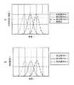
分光特性測定装置において、従来は、照明光としてキセノンランプやタングステンランプなどが用いられてきたが、近年では、その代わりに白色LED(Light Emitting Diode:発光ダイオード)等が用いられるようになってきている。しかし、キセノンランプやタングステンランプの波長に対する分光強度分布が比較的平坦であるのに対して、白色LEDの波長に対する分光強度分布は急峻である。ここで、分光強度分布が平坦であるとは、受光素子列の隣接する波長間において光の強度の変化が少ないことをいう。また、分光強度分布が急峻であるとは、受光素子列の隣接する波長間における光の強度が大きく変化することをいう。より具体的には、図9および図10を用いて説明する。図9はタングステンランプの波長に対する分光強度分布を示すグラフである。また、図10は白色LEDの波長に対する分光強度分布を示すグラフである。図9および図10において、横軸は波長であり縦軸は相対強度である。図9に示すように、タングステンランプは波長が大きくなるにつれて、相対強度も大きくなっている。しかし、急激に増加している箇所はなく、略単調増加であり、分光強度分布は平坦であるといえる。また、白色LEDの分光強度分布は、図10に示す例では、図9に示した波長帯域と同様であるにもかかわらずピークを2つ有している。つまり、所定の波長帯域に光強度の複数のピークを有し、図9と比べて、波長に対して、光強度が急激に増加および急激に減少している箇所がある。このように、図10に示した白色LEDの分光強度分布は、急峻であるといえる。 In a spectral characteristic measuring apparatus, conventionally, a xenon lamp, a tungsten lamp, or the like has been used as illumination light, but in recent years, a white LED (Light Emitting Diode) or the like has been used instead. Yes. However, while the spectral intensity distribution with respect to the wavelength of the xenon lamp or the tungsten lamp is relatively flat, the spectral intensity distribution with respect to the wavelength of the white LED is steep. Here, that the spectral intensity distribution is flat means that the change in light intensity is small between adjacent wavelengths of the light receiving element array. The steep spectral intensity distribution means that the light intensity changes greatly between adjacent wavelengths of the light receiving element array. More specifically, a description will be given with reference to FIGS. 9 and 10. FIG. 9 is a graph showing the spectral intensity distribution with respect to the wavelength of the tungsten lamp. FIG. 10 is a graph showing the spectral intensity distribution with respect to the wavelength of the white LED. 9 and 10, the horizontal axis represents wavelength and the vertical axis represents relative intensity. As shown in FIG. 9, the relative intensity of the tungsten lamp increases as the wavelength increases. However, there is no portion where the abrupt increase occurs, and the increase is substantially monotonous, and the spectral intensity distribution can be said to be flat. Further, the spectral intensity distribution of the white LED has two peaks in the example shown in FIG. 10, although it is similar to the wavelength band shown in FIG. That is, there are a plurality of peaks of the light intensity in a predetermined wavelength band, and there are places where the light intensity rapidly increases and decreases with respect to the wavelength as compared with FIG. Thus, it can be said that the spectral intensity distribution of the white LED shown in FIG. 10 is steep.
ここで、分光特性測定装置においては、測定試料に照射された照明光の反射光を分散させ、測定する。したがって、測定された値には、照明光の特性も反映される。しかし、従来のようにタングステンランプを照明光とした場合は、分光特性測定装置における受光部の各受光素子における受光感度とは、受光素子の性能に起因するものだけを考慮していればよかった。しかし、照明光に、上述のように、白色LED等のような、波長に対する分光強度分布が急峻なものを用いる場合には、受光感度に照明光の影響が強く出ることとなる。そこで、受光感度に対する照明光の影響について説明する。 Here, in the spectral characteristic measuring apparatus, the reflected light of the illumination light irradiated on the measurement sample is dispersed and measured. Therefore, the characteristic of illumination light is reflected in the measured value. However, when a tungsten lamp is used as illumination light as in the prior art, it is only necessary to consider the light receiving sensitivity of each light receiving element of the light receiving unit in the spectral characteristic measuring apparatus only due to the performance of the light receiving element. However, as described above, when the illumination light having a steep spectral intensity distribution with respect to the wavelength, such as a white LED, is used, the influence of the illumination light is strongly exerted on the light receiving sensitivity. Therefore, the influence of illumination light on the light receiving sensitivity will be described.
分光特性測定装置における受光感度について図11〜図14を用いて説明する。図11は照明光をタングステンランプとした場合における受光素子の受光感度について説明する第1のグラフであって、図11(A)は受光素子の受光感度および照明光の光強度を示すグラフであり、図11(B)は受光素子の合成感度を示すグラフである。また、図12は照明光を白色LEDとした場合における受光素子の受光感度について説明する第1のグラフであって、図12(A)は受光素子の受光感度および照明光の光強度を示すグラフであり、図12(B)は受光素子の合成感度を示すグラフである。また、図13は照明光をタングステンランプとした場合における受光感度について説明する第2のグラフであって、図13(A)は各受光素子の受光感度を示すグラフであり、図13(B)は重み付け後の受光感度を示すグラフである。また、図14は照明光を白色LEDとした場合における受光感度について説明する第2のグラフであって、図14(A)は受光素子の受光感度を示すグラフであり、図14(B)は重み付け後の受光感度を示すグラフである。なお、図11〜図14において、横軸は波長であり、縦軸は受光素子の相対感度または照明光の相対強度である。また、図11、図12における、受光素子No.1〜No.3は、それぞれ隣接する3つの受光素子を示しており、これらの受光素子No.1〜No.3の順に並んで配列されている。 The light receiving sensitivity in the spectral characteristic measuring apparatus will be described with reference to FIGS. FIG. 11 is a first graph for explaining the light receiving sensitivity of the light receiving element when the illumination light is a tungsten lamp. FIG. 11A is a graph showing the light receiving sensitivity of the light receiving element and the light intensity of the illumination light. FIG. 11B is a graph showing the combined sensitivity of the light receiving elements. FIG. 12 is a first graph for explaining the light receiving sensitivity of the light receiving element when the illumination light is a white LED. FIG. 12A is a graph showing the light receiving sensitivity of the light receiving element and the light intensity of the illumination light. FIG. 12B is a graph showing the combined sensitivity of the light receiving elements. FIG. 13 is a second graph for explaining the light receiving sensitivity when the illumination light is a tungsten lamp. FIG. 13A is a graph showing the light receiving sensitivity of each light receiving element, and FIG. Is a graph showing the light receiving sensitivity after weighting. FIG. 14 is a second graph for explaining the light receiving sensitivity when the illumination light is a white LED. FIG. 14A is a graph showing the light receiving sensitivity of the light receiving element, and FIG. It is a graph which shows the light reception sensitivity after weighting. 11 to 14, the horizontal axis represents the wavelength, and the vertical axis represents the relative sensitivity of the light receiving element or the relative intensity of the illumination light. In addition, in FIG. 11 and FIG. 1-No. 3 shows three light receiving elements adjacent to each other. 1-No. They are arranged in the order of 3.
照明光をタングステンランプとした場合は、図11(A)に示すように、各受光素子における受光感度および照明光の分光強度分布が得られる。図11(A)に示すように、照明光の分光強度分布は平坦である。また、図11(A)で示している各受光素子の感度は、照明光の影響を受けていない状態での値である。実際の測定においては、照明光の影響も加わることから、その場合の合成感度は、図11(B)に示すような値となる。この合成感度は、具体的には、各受光素子における受光感度と照明光の光強度とを乗じることで求められる。図11(A)および図11(B)を比べることでわかるように、両者において、各受光素子No.1〜No.3における中心波長は略一定である。 When the illumination light is a tungsten lamp, as shown in FIG. 11A, the light receiving sensitivity and the spectral intensity distribution of the illumination light in each light receiving element are obtained. As shown in FIG. 11A, the spectral intensity distribution of the illumination light is flat. Further, the sensitivity of each light receiving element shown in FIG. 11A is a value in a state where it is not affected by illumination light. In actual measurement, the influence of illumination light is also added, so the combined sensitivity in that case is a value as shown in FIG. Specifically, the combined sensitivity is obtained by multiplying the light receiving sensitivity of each light receiving element and the light intensity of the illumination light. As can be seen from a comparison between FIG. 11A and FIG. 1-No. The center wavelength at 3 is substantially constant.
また、照明光を白色LEDとした場合は、図12(A)に示すように、各受光素子における受光感度および照明光の分光強度分布が得られる。図12(A)に示すように、照明光の分光強度分布は急峻であり、タングステンランプに比べてその傾きが大きい。また、図12(A)で示している各受光素子の感度は、図11(A)と同様に、照明光の影響を受けていない状態での値である。照明光の影響も加えた場合の合成感度は、図12(B)に示すような値となる。図12(A)および図12(B)を比べることでわかるように、両者において、各受光素子No.1〜No.3における中心波長の位置がずれている。具体的には、照明光の光強度が波長の増加とともに急激に増加する場合は、合成感度による中心波長は、受光素子の性能のみにより算出された中心波長に比べて増加している。 When the illumination light is a white LED, as shown in FIG. 12A, the light receiving sensitivity and the spectral intensity distribution of the illumination light in each light receiving element are obtained. As shown in FIG. 12A, the spectral intensity distribution of the illumination light is steep, and its inclination is larger than that of the tungsten lamp. Further, the sensitivity of each light receiving element shown in FIG. 12A is a value in a state where it is not affected by illumination light, as in FIG. 11A. The combined sensitivity when the influence of illumination light is added is a value as shown in FIG. As can be seen from a comparison between FIG. 12A and FIG. 1-No. 3 is shifted in the position of the center wavelength. Specifically, when the light intensity of the illumination light increases rapidly as the wavelength increases, the center wavelength due to the combined sensitivity increases compared to the center wavelength calculated only by the performance of the light receiving element.
このように、照明光としてタングステンランプを用いる場合には、影響がほとんどなかったが、白色LED等のように、波長に対する分光強度分布は急峻な照明光を用いる場合には、照明光の影響を受けていない状態での中心波長を記憶しておき、その値を用いて測定値を補間等しても、正確な測定値を求めることは困難である。 As described above, when a tungsten lamp is used as the illumination light, there was almost no influence. However, when using the illumination light having a steep spectral intensity distribution with respect to the wavelength, such as a white LED, the influence of the illumination light is reduced. It is difficult to obtain an accurate measurement value even if the center wavelength in a state where it is not received is stored and the measurement value is interpolated using the value.
また、例えば、受光素子の受光感度に、その受光素子に隣接する複数の受光素子における受光感度それぞれに重み付けを施し加算することで、受光素子の受光感度の精度を向上させ、S/N比を向上させる方法がある。そのような場合に、タングステンランプを照明光とした場合には、まず、中央受光素子(受光素子No.2)とそれに隣接する受光素子(受光素子No.1および3)の受光感度は、図13(A)に示すように求められる。なお、図13(A)に示す各受光素子の合成感度は、図11(B)の各受光素子の合成感度に対応する。図13(A)に示すように、隣接する受光素子である受光素子No.1および3の合成感度はほとんど変わらないので、重み付けのための重み係数は、左右対称とすればよい。そして、これら受光素子No.1〜No.3の合成感度を用いて、重み付け演算することで、図13(B)に示す合成感度を求めることができる。図13(A)および図13(B)を比べることでわかるように、図13(B)に示す合成中心波長と、図13(A)に示す受光素子No.2の合成中心波長とはほぼ同一であり、ほとんどずれが生じていない。なお、合成中心波長とは、合成感度をもとに算出した受光素子の中心波長をいう。次に、白色LEDを照明光とした場合について説明する。白色LEDを照明光とした場合には、まず、中央受光素子(受光素子No.2)とそれに隣接する受光素子(受光素子No.1および3)の合成感度は図14(A)に示すように求められる。なお、図14(A)に示す各受光素子の合成感度は、図12(B)の各受光素子の合成感度に対応する。これらの合成感度に応じて、適当な重み係数を用いて重み付け演算することで、図14(B)に示す合成感度を求めることができる。図14(A)および図14(B)を比べることでわかるように、図14(B)に示す合成中心波長は、図14(A)に示す受光素子No.2の中心波長よりも大きい値となり、ずれが生じている。 In addition, for example, by adding a weight to each light receiving sensitivity of a plurality of light receiving elements adjacent to the light receiving element to the light receiving sensitivity of the light receiving element, the accuracy of the light receiving sensitivity of the light receiving element is improved, and the S / N ratio is increased. There are ways to improve it. In such a case, when a tungsten lamp is used as illumination light, first, the light receiving sensitivity of the central light receiving element (light receiving element No. 2) and the light receiving elements adjacent thereto (light receiving elements No. 1 and 3) are as shown in FIG. 13 (A). Note that the combined sensitivity of each light receiving element shown in FIG. 13A corresponds to the combined sensitivity of each light receiving element in FIG. As shown in FIG. 13A, the light receiving element No. Since the combined sensitivities of 1 and 3 hardly change, the weighting coefficient for weighting may be symmetrical. These light receiving elements No. 1-No. By performing the weighting calculation using the composite sensitivity of 3, the composite sensitivity shown in FIG. 13B can be obtained. As can be seen by comparing FIG. 13 (A) and FIG. 13 (B), the composite center wavelength shown in FIG. 13 (B) and the light receiving element No. 1 shown in FIG. 2 is almost the same as the synthetic center wavelength, and there is almost no deviation. The synthetic center wavelength means the center wavelength of the light receiving element calculated based on the synthetic sensitivity. Next, a case where a white LED is used as illumination light will be described. When the white LED is used as illumination light, first, the combined sensitivity of the central light receiving element (light receiving element No. 2) and the adjacent light receiving elements (light receiving elements No. 1 and 3) is as shown in FIG. Is required. Note that the combined sensitivity of each light receiving element shown in FIG. 14A corresponds to the combined sensitivity of each light receiving element in FIG. A composite sensitivity shown in FIG. 14B can be obtained by performing a weighting operation using an appropriate weighting coefficient in accordance with the composite sensitivity. As can be seen by comparing FIG. 14A and FIG. 14B, the combined center wavelength shown in FIG. The value is larger than the center wavelength of 2, and a deviation occurs.
このように、タングステンランプの代わりに、白色LEDを照明光として用いることで、照明光の影響を受けていない状態での受光素子の受光感度のみに基づいて、中心波長等を求めて測定の際にそれを用いて測定値を補間しても、実際の分光特性測定においては、上述のように照明光の影響も出ることから正確な測定値を得ることはできない。 As described above, when a white LED is used as illumination light instead of a tungsten lamp, the center wavelength or the like is obtained based on only the light receiving sensitivity of the light receiving element in the state not affected by the illumination light. Even if the measured values are interpolated using the same, in the actual spectral characteristic measurement, the influence of the illumination light is also produced as described above, so that an accurate measured value cannot be obtained.
本発明は、上述の事情に鑑みて為された発明であり、その目的は、出荷前の校正がより正確に行われた分光特性測定装置、分光特性測定装置をより正確に校正する方法およびより正確な分光特性を測定できる分光特性測定システムを提供することである。 The present invention has been made in view of the above-described circumstances, and its object is to provide a spectral characteristic measuring apparatus in which calibration before shipping is performed more accurately, a method for more accurately calibrating the spectral characteristic measuring apparatus, and more To provide a spectral characteristic measurement system capable of measuring accurate spectral characteristics.
本発明者は、種々検討した結果、上記目的は、以下の本発明により達成されることを見出した。すなわち、本発明の一態様に係る分光特性測定装置は、測定試料に照明光を照射する照明部と、前記照明光を照射された前記測定試料からの放射光を波長ごとに分散させる分光部と、前記分光部により分散された光を波長ごとに受光し、電気信号に変換して出力する複数の受光素子を有する受光部と、前記照明光の分光強度分布に基づいて予め算出された、前記受光素子の合成中心波長を記憶する記憶部とを備えている。 As a result of various studies, the present inventor has found that the above object is achieved by the present invention described below. That is, the spectral characteristic measurement apparatus according to an aspect of the present invention includes an illumination unit that irradiates a measurement sample with illumination light, and a spectroscopy unit that disperses radiation light from the measurement sample irradiated with the illumination light for each wavelength. A light receiving unit having a plurality of light receiving elements that receive light dispersed by the spectral unit for each wavelength, convert the light into an electrical signal, and output the spectral intensity distribution of the illumination light; And a storage unit that stores the combined center wavelength of the light receiving element.
これにより、照明光の波長に対する分光強度分布が急峻であっても、実際の測定時における受光素子の中心波長(合成中心波長)を予め記憶部に記憶しているため、測定の際に、測定値と記憶されている中心波長とに基づいて演算することにより、より正確な分光特性を測定することができる。 As a result, even if the spectral intensity distribution with respect to the wavelength of the illumination light is steep, the center wavelength (synthetic center wavelength) of the light receiving element at the time of actual measurement is stored in the storage unit in advance, so measurement is performed during measurement. By calculating based on the value and the stored center wavelength, more accurate spectral characteristics can be measured.
また、上述の分光特性測定装置において、前記合成中心波長は、前記受光素子に対する前記照明光の光強度および当該受光素子の受光感度に基づいて算出された、受光素子の合成感度により算出されることが好ましい。 In the spectral characteristic measuring apparatus described above, the combined center wavelength is calculated by a combined sensitivity of the light receiving element calculated based on a light intensity of the illumination light with respect to the light receiving element and a light receiving sensitivity of the light receiving element. Is preferred.
これにより、記憶部に予め記憶される中心波長は、実際の測定時における受光素子の中心波長である。したがって、より正確な分光特性を測定することができる。 As a result, the center wavelength stored in advance in the storage unit is the center wavelength of the light receiving element during actual measurement. Therefore, more accurate spectral characteristics can be measured.
また、上述の分光特性測定装置において、前記受光素子の合成感度は、さらに当該受光素子の周辺に配置された受光素子の前記合成感度を考慮して算出されていることが好ましい。 In the above-described spectral characteristic measuring apparatus, it is preferable that the combined sensitivity of the light receiving element is calculated in consideration of the combined sensitivity of the light receiving elements arranged around the light receiving element.
これにより、受光素子から出力された電気信号を、例えば、重み付け加算演算により処理するため、S/N(signal to noise ratio)比が向上し、かつ、中心波長は実際の測定時における受光素子の実質的な中心波長となるので、より正確な分光特性を測定することができる。 As a result, the electrical signal output from the light receiving element is processed by, for example, weighted addition calculation, so that the S / N (signal to noise ratio) ratio is improved, and the center wavelength is determined by the light receiving element at the time of actual measurement. Since it becomes a substantial center wavelength, more accurate spectral characteristics can be measured.
また、上述の分光特性測定装置において、前記記憶部は、前記照明光の分光強度分布を考慮せずに、前記受光素子の受光感度に基づいて予め算出された、前記受光素子の受光系中心波長と、光源色を測定する際に、測定値を算出するための基準となる、レベル校正係数とをさらに記憶していることが好ましい。 Further, in the above-described spectral characteristic measuring apparatus, the storage unit may calculate a light receiving system center wavelength of the light receiving element calculated in advance based on the light receiving sensitivity of the light receiving element without considering the spectral intensity distribution of the illumination light. In addition, it is preferable to further store a level calibration coefficient serving as a reference for calculating a measurement value when measuring the light source color.
これにより、分光特性測定装置を、物体色測定だけでなく、光源色測定用にも使用することができる。 Thereby, the spectral characteristic measuring apparatus can be used not only for object color measurement but also for light source color measurement.
また、上述の分光特性測定装置において、前記照明部は白色発光ダイオードであることが好ましい。 Moreover, in the above-described spectral characteristic measurement apparatus, the illumination unit is preferably a white light emitting diode.
これにより、照明光の長寿命化、小型化、軽量化等を実現できる。 As a result, it is possible to realize a longer life, smaller size, lighter weight and the like of the illumination light.
また、本発明の一態様に係る分光特性測定装置の校正方法は、測定試料に照明光を照射し、前記測定試料からの放射光を波長ごとに分散させ、分散された光を複数の受光素子で受光し、電気信号に変換して出力する分光特性測定装置の校正方法であって、前記受光素子の受光感度を取得する工程と、前記受光素子に対する前記照明光の光強度を取得する工程と、前記取得した、前記受光感度および前記照明光の光強度に基づいて、前記受光素子の合成感度を算出する工程と、前記合成感度より前記受光素子の合成中心波長を算出する工程と、前記合成中心波長を前記分光特性測定装置に記憶させる工程とを備えている。 Further, the calibration method of the spectral characteristic measurement apparatus according to one aspect of the present invention is configured to irradiate a measurement sample with illumination light, disperse the emitted light from the measurement sample for each wavelength, and distribute the dispersed light to a plurality of light receiving elements. A method for calibrating a spectral characteristic measuring device that receives light at the light source, converts it into an electrical signal, and outputs it, the step of obtaining the light receiving sensitivity of the light receiving element, and the step of obtaining the light intensity of the illumination light with respect to the light receiving element; Calculating the combined sensitivity of the light receiving element based on the acquired light receiving sensitivity and the light intensity of the illumination light; calculating the combined center wavelength of the light receiving element from the combined sensitivity; and the combining Storing the center wavelength in the spectral characteristic measuring apparatus.
これにより、照明光の波長に対する分光強度分布が急峻であっても、測定の際にその影響を受けずに、より正確な分光特性を測定できるように校正することができる。 Thereby, even if the spectral intensity distribution with respect to the wavelength of the illumination light is steep, it can be calibrated so that more accurate spectral characteristics can be measured without being influenced by the measurement.
また、本発明の一態様に係る分光特性測定システムは、測定試料に照明光を照射する照明部と、前記照明光を照射された前記測定試料からの放射光を波長ごとに分散させる分光部と、前記分光部により分散された光を波長ごとに受光し、電気信号に変換して出力する複数の受光素子を有する受光部と、前記複数の受光素子の出力と、前記照明光の分光強度分布に基づいて予め算出された前記受光素子の合成中心波長とを用いて、前記測定試料の分光特性を算出する演算装置とを備えている。なお、演算装置とは、例えばパーソナルコンピュータ等である。 In addition, the spectral characteristic measurement system according to one aspect of the present invention includes an illumination unit that irradiates a measurement sample with illumination light, and a spectroscopy unit that disperses radiation light from the measurement sample irradiated with the illumination light for each wavelength. A light receiving unit having a plurality of light receiving elements that receive the light dispersed by the spectral unit for each wavelength, convert the light into an electrical signal, and output, and the spectral intensity distribution of the illumination light And an arithmetic unit that calculates the spectral characteristic of the measurement sample using the synthetic center wavelength of the light receiving element calculated in advance based on the above. The arithmetic device is, for example, a personal computer.
このように、分光特性測定システムは、受光部と、分光部と、照明部とを有する分光特性測定装置と、演算装置とを備えている。それにより、照明光の波長に対する分光強度分布が急峻であっても、実際の測定時における受光素子の中心波長(合成中心波長)と、測定値とを用いて分光特性を算出するので、より正確な分光特性を測定することができる。 As described above, the spectral characteristic measurement system includes the spectral characteristic measurement device including the light receiving unit, the spectral unit, and the illumination unit, and the arithmetic unit. As a result, even if the spectral intensity distribution with respect to the wavelength of the illumination light is steep, the spectral characteristics are calculated using the center wavelength (synthetic center wavelength) of the light receiving element and the measured value at the time of actual measurement. Spectroscopic characteristics can be measured.
本発明によれば、出荷前の校正がより正確に行われた分光特性測定装置および分光特性測定装置をより正確に校正する方法を提供することができる。 According to the present invention, it is possible to provide a spectral characteristic measuring apparatus in which calibration before shipping is performed more accurately and a method for more accurately calibrating the spectral characteristic measuring apparatus.
以下、本発明に係る実施の形態を図面に基づいて説明する。なお、各図において同一の符号を付した構成は、同一の構成であることを示し、その説明を省略する。 Embodiments according to the present invention will be described below with reference to the drawings. In addition, the structure which attached | subjected the same code | symbol in each figure shows that it is the same structure, The description is abbreviate | omitted.
(実施の形態1)
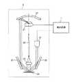
本発明の実施の形態1に係る分光特性測定システムについて説明する。まず、実施の形態1に係る分光特性測定システムの構成について説明する。図1は実施の形態1に係る分光特性測定システムの構成を説明するための図である。図2は実施の形態1に係る分光特性測定装置の測定部の構成を示す側面図である。図2は図1に示された測定部2の側面図を示すものであり、測定部2は、図1に示されていないが、紫色LED27を備え、紫色LED27は発光回路1に接続されている。また、図3は実施の形態1に係る分光特性測定装置の測定部において、白色LEDよりも下側の構成を示す上面図である。(Embodiment 1)
A spectral characteristic measurement system according to
図1に示すように、実施の形態1に係る分光特性測定システムSは、分光特性測定装置100と演算装置であるパーソナルコンピュータ(以下、パソコンという)6とを備えて構成される。分光特性測定装置100は、発光回路1と、測定部2と、分光測定部3と、制御部4と、測定トリガ5とを備えて構成され、例えば、測定試料24の色を分析する分光測色計等である。また、パソコン6は分光特性測定装置100において、測定した値を演算、表示等する。 As shown in FIG. 1, the spectral characteristic measurement system S according to
発光回路1は、測定部2に備えられた照明部である白色LED21および紫色LED27を点灯させるための回路であり、例えば、電子回路部品により構成されている。 The
測定部2は、照明部である白色LED21と、白色LED21の上部に配置された反射ミラー22と、トロイダルミラー23と、測定試料24と、レンズ25と、オプティカルファイバ26と、紫色LED27とを備えて構成されている。 The
白色LED21は照明部であり、測定試料24を照らす白色光を出射する。反射ミラー22は白色LED21から出射された白色光をリング状に反射して、トロイダルミラー23へと導く。トロイダルミラー23は、横方向と縦方向の曲率が異なる非球面反射鏡であり、球面鏡と比べて、点光源からの光を試料面全体に、均一に照射できるという効果を奏する。さらに、紫外から赤外までの幅広い波長域に対応できる。トロイダルミラー23は、反射ミラー22からのリング状である白色光および一方向からの紫色LED27から出射された紫色光を反射させて、測定試料24にこれらの光を導き照射する。紫色LED27は、白色LED21からの照明光を補うために設けられている。すなわち、白色LED21から出射される白色光は、短波長(420nm程度)のエネルギーが比較的低い。そこで、紫色LED27から出射される短波長のエネルギーを有する、例えば主波長が410nmである紫色光により照明光を補うこととしている。測定試料24は測定対象物である。トロイダルミラー23において反射した白色光および紫色光は測定試料24に照射され、測定試料24にて反射される。レンズ25は測定試料24の上方に位置し、測定試料24からの反射光を集束させてオプティカルファイバ26に結合させる。オプティカルファイバ26は測定試料24からの光(反射光)を分光測定部3に導く。 The
分光測定部3は、入射スリット31と、分光部である回折格子32と、複数の受光素子が同一直線状に並ぶように配置された、受光部である受光ラインセンサ33とを備えている。入射スリット31は、オプティカルファイバ26により導かれた測定試料24からの光を分光測定部3内に入射させる。回折格子32は、入射スリット31を介することで、帯状の光束とされた測定試料24からの光を波長ごとに分光させる。具体的には、回折格子32に入射された光は、波長ごとに異なる反射方向に反射される。したがって、所定の方向に沿って異なる波長の光が並んで反射される。なお、実施の形態1では、回折格子32は反射型としているが、例えば透過型回折格子としてもよい。受光ラインセンサ33は複数の受光素子が並んで配列されていて、その配列方向は、回折格子32により分散する方向と同一である。このような構成であることから、回折格子32で分光された、それぞれ異なる波長の光が各受光素子に入射される。これら光が入射することで、受光素子はその光に応じた電気信号を出力する。例えば、128個の受光素子を配列し、それぞれの測定ピッチは4nmとすればよい。なお、出力された電気信号は制御部4へ送られる。 The
制御部4は、各種電子部品や集積回路部品、CPU(Central Processing Unit)等からなり、分光特性測定装置100の各部の動作制御を行う測定制御部41と、分光測定部3からの電気信号をもとに、各種演算を行う演算処理部42とを備え、さらに、分光特性測定装置100の演算処理や制御処理等のプログラムや出荷時に予め求めた校正データ等を記憶するROM(Read Only Memory)、EEPROM(Electrically Erasable Programmable ROM)、フラッシュメモリ等の不揮発性メモリや、データを一時的に格納するRAM(Random Access Memory)等を備える記憶部43とを備えて構成される。 The control unit 4 includes various electronic components, integrated circuit components, a CPU (Central Processing Unit), and the like. The control unit 4 controls the operation of each unit of the spectral
測定トリガ5は、分光特性の測定開始の指示を行うためのスイッチである。 The measurement trigger 5 is a switch for instructing the start of measurement of spectral characteristics.
パソコン6は、分光特性測定装置100の外部機器であり、例えばUSB等のインターフェースを介して分光特性測定装置100と接続されている。パソコン6は、演算を行うためのCPUや、ROM、EEPROM、RAM、フラッシュメモリ等の記憶部を有する。さらに、図示はしていないが、測定結果をモニタするための、例えばLCD(Liquid Crystal Display)や有機エレクトロルミネッセンス表示装置やCRT(Cathode-Ray Tube)表示装置等の表示装置も有している。また、パソコン6はCD−ROM(Compact Disc Read Only Memory)やメモリーカード等の補助記録媒体を装着あるいは脱着可能であり、これら補助記録媒体からのデータの読み出しや、補助記録媒体へのデータの書き込みが可能である。それにより、パソコン6の演算において用いるデータを記録した補助記録媒体をパソコン6に装着して演算に必要なデータを読み出したり、パソコン6が算出したデータを補助記録媒体により保存しておくこと等が可能である。そして、パソコン6は、測定値の演算、測定結果の表示等、分光特性測定装置100の補助的な働きをする。 The personal computer 6 is an external device of the spectral
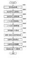
次に、実施の形態1に係る分光特性測定装置100の出荷時における校正方法について図4を用いて説明する。図4は実施の形態1に係る分光特性測定装置の校正方法を示すフローチャートである。まず、従来と同様に、照明光の影響を受けない場合の受光部33における各受光素子の受光感度を取得する(S101)。具体的には、半値幅の十分に小さい単色光を出力可能な照射型分光器等により、分光測定部3に各波長成分の単色光を順次出力させる。各単色光は回折格子32にて波長ごとに異なる角度で反射され、並んで配列された受光ラインセンサ33の各受光素子に照射される。光が照射された受光素子は、電気信号を出力する。この受光ラインセンサ33からの電気信号をプロットすることで、各受光素子の受光感度を取得することができる。 Next, a calibration method at the time of shipment of the spectral
次に、照明光の分光強度分布を取得する(S102)。具体的には、分光放射輝度計等を用いて、白色LED21および紫色LED27から出射される照明光を測定することで、照明光の波長に対する分光強度分布を取得することができる。 Next, the spectral intensity distribution of the illumination light is acquired (S102). Specifically, the spectral intensity distribution with respect to the wavelength of the illumination light can be acquired by measuring the illumination light emitted from the
次に、これら受光素子の受光感度と照明光の分光強度分布とを基に、これらの特性を含む合成感度を算出する(S103)。ここで、fn(λ)はn番目の受光素子における合成感度であり、In(λ)はn番目の受光素子に入射される照明光の光強度であり、Dn(λ)はn番目の受光素子における受光感度であるとすると、fn(λ)は以下の式1により求められる。なお、受光ラインセンサ33が128個の受光素子を備えている場合は、nは1〜128の整数である。Next, based on the light receiving sensitivity of these light receiving elements and the spectral intensity distribution of the illumination light, the combined sensitivity including these characteristics is calculated (S103). Here, fn (λ) is the combined sensitivity of the n th light receiving element, In (λ) is the light intensity of the illumination light incident on the n th light receiving element, and Dn (λ) is n If it is the light receiving sensitivity in the second light receiving element, fn (λ) is obtained by the
fn(λ)=In(λ)×Dn(λ) ・・・(1)
具体的には、照明光の光強度と受光素子の受光感度を乗じることで、この分光特性測定装置100の各受光素子における合成感度を求めることができる。このようにして、算出した合成感度を用いて、各受光素子における中心波長(合成中心波長)を算出する(S104)。受光素子ごとの受光感度特性における重心を中心波長とすればよい。そこで、重心である中心波長をλgとし、波長をλとし、この波長λにおける合成感度をS(λ)とすると、中心波長は、以下の式2で表すことができる。fn (λ) = In (λ) × Dn (λ) (1)
Specifically, the combined sensitivity of each light receiving element of the spectral

なお、各受光素子の中心波長は、分光特性測定装置100を調整するための装置により算出すればよい。分光特性測定装置100を調整するための装置は、例えばパソコン等とすればよい。 The center wavelength of each light receiving element may be calculated by a device for adjusting the spectral
このようにして、算出された各受光素子の中心波長は校正データの1つとして記憶部43に記憶される(S105)。なお、中心波長の算出は演算処理部42でなされればよい。 In this way, the calculated center wavelength of each light receiving element is stored in the
さらに、キャリブレーション用のデータである白色校正板データを記憶部43に記憶させる(S106)。なお、白色校正板データは、それぞれの装置に固有のデータではなく、それぞれの白色校正板に固有のデータである。 Further, white calibration plate data, which is calibration data, is stored in the storage unit 43 (S106). Note that the white calibration plate data is not data unique to each device but data unique to each white calibration plate.
また、算出された中心波長や白色校正板のデータは、パソコン6を介して補助記録媒体に記憶されてもよい。すなわち、分光特性測定装置100と、合成中心波長データを記憶した補助記録媒体との組み合わせで測定するシステムを構成するようにしてもよい。 The calculated center wavelength and white calibration plate data may be stored in the auxiliary recording medium via the personal computer 6. That is, a system for measurement may be configured by a combination of the spectral
以上の工程で、出荷前の分光特性測定装置100の校正が終了する。本実施の形態1に係る分光特性測定装置100は、上述のように、記憶部43に校正データを記憶している。校正データとしては、照明光の波長に対する分光強度分布に基づいて算出された、各受光素子における合成中心波長および白色校正板データである。 With the above steps, calibration of the spectral
次に、この分光特性測定装置100を用いて、測定試料24の分光特性を測定する方法について図5を用いて説明する。図5は実施の形態1に係る分光特性測定システムを用いた測定方法を示すフローチャートである。まず、測定前の校正を行う。図1に示した、実施の形態1に係る分光特性測定システムSにおいて、白色校正板を測定試料24として設置する。測定トリガ5を操作することで、測定が開始される。まず、オフセット補正を行うため、照明光は照射せずに測定を行う。つまり、白色校正板によるオフセット測光が行われる(S201)。具体的には、測定トリガ5からの測定開始の信号が入力されると、測定動作を行うよう、制御部4の測定制御部41は各部品を制御する。照明光が照射されない状態であるため、測定試料24から反射される光もない。つまり、反射率が0の状態の測定値が測定される。この際に出力された電気信号は制御部4に入力され、いったん記憶部43に記憶される。 Next, a method for measuring the spectral characteristics of the
次に、照明光を照射した状態での、白色校正板の測光を行う(S202)。具体的には、測定制御部41は、発光回路1に、白色LED21および紫色LED27から、白色光および紫色光を出射させる。白色光は白色LED21の上方に設置された反射ミラー22に入射して反射し、トロイダルミラー23に入射する。紫色光は、直接トロイダルミラー23に入射する。そして、それらはトロイダルミラー23で反射し、白色校正板である測定試料24に照射される。測定試料24に白色光および紫色光が照射されることにより、測定試料24でそれらが反射して、その反射光がレンズ25で集束され、オプティカルファイバ26に結合される。反射光はオプティカルファイバ26中を伝播して、分光測定器3の入射スリット31を介して回折格子32に入射する。回折格子32において、前記反射光は分散され、すなわち波長ごとに異なる反射角度で反射され、受光ラインセンサ33に入射される。それにより、各受光素子に光が入力され、電気信号として出力される。出力された電気信号は制御部4に入力され、パソコン6に送られる。 Next, photometry is performed on the white calibration plate in a state where illumination light is irradiated (S202). Specifically, the
これら、白色校正板による測定値は、分光特性測定における基準とされる。パソコン6はステップS202において測定したデータと、ステップS201において測定したデータとの差を演算することでオフセット補正演算を行う(S203)。これにより算出された白色校正カウント値はパソコン6に記憶される。 These measured values by the white calibration plate are used as a reference in spectral characteristic measurement. The personal computer 6 performs an offset correction calculation by calculating the difference between the data measured in step S202 and the data measured in step S201 (S203). The white calibration count value calculated in this way is stored in the personal computer 6.
ステップS201〜S203によって、実施の形態1に係る分光特性測定システムSの測定前の校正が完了する。次に、実際の測定試料24の測定を開始する。まず、照明光を照射せずに、上記ステップS201と同様に、オフセット測光を行う(S204)。そして、測光により、受光ラインセンサ33の各受光素子から電気信号が出力され、出力された電気信号は制御部4に入力され、パソコン6に送られて記憶される。 Through steps S201 to S203, the calibration before the measurement of the spectral characteristic measurement system S according to the first embodiment is completed. Next, measurement of the
次に、ステップS202と同様に、照明光を照射した状態での、測定試料24の測光を行う(S205)。そして、測光により、受光ラインセンサ33の各受光素子から電気信号が出力され、出力された電気信号は制御部4に入力され、パソコン6に送られて記憶される。 Next, as in step S202, photometry is performed on the
これら、ステップS204およびステップS205において測定されたデータをもとに、パソコン6は測定試料24のオフセット補正演算を行う(S206)。具体的には、ステップS203と同様に、ステップS205において測定したデータと、ステップS204において測定したデータとの差を演算することで、各受光素子の測光カウント値を求める。パソコン6はさらに、このようにして求めた、測定試料24における測光カウント値と、ステップS203で求めた白色校正カウント値との比率(測光カウント比率)を演算により求める(S207)。なお、このようにして得られた、各受光素子における測光カウント値は、その各受光素子に対応する中心波長における値である。すなわち、校正データである合成感度により算出された各受光素子に対応する中心波長(合成中心波長)における値である。そこで、任意の波長における測光カウント値に換算するため、3次補間を行う(S208)。パソコン6は、このようにして、求めた任意の波長における測光カウント値および白色校正カウント値等から、各波長の反射率を求める(S209)。測定試料24の反射率をRef(λ)とし、測定試料24の測光カウント値をCs(λ)とし、白色校正板カウント値をCc(λ)とし、出荷時に記憶部43に記憶された校正データであり、白色校正板の真の値である白色校正板データをW(λ)とすると、測定試料24の反射率Ref(λ)は、以下に示す式3で表すことができる。
Ref(λ)=(Cs(λ)/Cc(λ))・W(λ) ・・・(3)
このようにして、得られた各波長における反射率をもとにパソコン6は色彩演算を行う(S210)。さらに、パソコン6は得られた反射率および色彩演算の結果を表示する(S211)。Based on the data measured in step S204 and step S205, the personal computer 6 performs an offset correction calculation of the measurement sample 24 (S206). Specifically, similarly to step S203, the photometric count value of each light receiving element is obtained by calculating the difference between the data measured in step S205 and the data measured in step S204. The personal computer 6 further obtains a ratio (photometric count ratio) between the photometric count value in the
Ref (λ) = (Cs (λ) / Cc (λ)) · W (λ) (3)
In this way, the personal computer 6 performs color calculation based on the obtained reflectance at each wavelength (S210). Furthermore, the personal computer 6 displays the obtained reflectance and color calculation results (S211).
上述の実施の形態1に係る分光特性測定システムSを用いて、実際に測定し、従来の分光特性測定システムと比較した。図6は実施の形態1の分光特性測定装置と、照明光として白色LEDを用いた従来の分光特性測定装置との性能評価を示すグラフである。図6においては、反射率が既知である測定試料24を、それぞれの分光特性測定装置を用いて測定し、その測定結果と既知の反射率との差を示している。図6中、一点鎖線で示した反射率は、照明光である白色LEDから出射された白色光の波長ごとの反射率Ref、すなわち光強度を表している。また、破線は、照明光として白色LEDを用いた従来の分光特性測定装置で求めた反射率と既知の反射率との差ΔRefを示している。また、実線は、実施の形態1の分光特性測定装置で求めた反射率と既知の反射率との差ΔRefを示している。図6に示されているように、白色LEDの波長の変化に対して、反射率の変化が顕著な箇所、具体的には波長が約500nm以下においては、破線で示した従来例は、0パーセントから外れた値となっているが、実線で示した実施の形態1は、全波長域において、略0パーセントである。このように、白色LEDを照明光として用いた場合でも、実施の形態1に係る分光特性測定装置においては、高精度を維持している。 Using the spectral characteristic measurement system S according to the first embodiment described above, the measurement was actually performed and compared with the conventional spectral characteristic measurement system. FIG. 6 is a graph showing performance evaluation of the spectral characteristic measuring apparatus according to the first embodiment and a conventional spectral characteristic measuring apparatus using a white LED as illumination light. In FIG. 6, the
なお、分光特性測定装置100においては、1つの受光素子の合成感度だけでなく、例えばその受光素子に隣接する受光素子の合成感度を重み付け演算することで、受光素子の合成感度を算出してもよい。それにより、S/N(signal to noise ratio)比の向上等の効果を奏する。なお、重み付け演算に用いる合成感度は隣接する受光素子によるものだけでなく、それ以外の受光素子の合成感度でもよい。また、例えば、隣接する受光素子の合成感度を用いて重み付け演算する場合は、隣接する受光素子の合成感度には0.25を乗じ、中央受光素子の合成感度には0.5を乗じたものを加算する等すればよい。このように、重み付け演算を用いて、分光特性を測定する分光特性測定装置100の場合は、図4で示した校正方法においては、ステップS103において、合成感度を算出した後に、重み付け演算を行い算出された合成感度をもとに、ステップS104において中心波長を算出すればよい。具体的には、以下に示す式4を用いて、重み付け演算後の合成感度を求めればよい。ここで、n番目の受光素子における重み付け演算後の合成感度をTn(λ)とし、n番目の受光素子における合成感度をfn(λ)とし、各合成感度に乗じるウェイトを、W1およびW2とする。なお、W1は両隣の受光素子の合成感度に乗じるウェイトであり、W2は中央受光素子の合成感度に乗じるウェイトである。In the spectral
Tn(λ)=W1fn−1(λ)+W2fn(λ)+W1fn+1(λ)・・・(4)
このようにして、求めた合成感度Tn(λ)を用いて中心波長を求めればよい。Tn (λ) = W1 fn−1 (λ) + W2 fn (λ) + W1 fn + 1 (λ) (4)
In this way, the center wavelength may be obtained using the obtained synthetic sensitivity Tn (λ).
また、このように、重み付け演算による合成感度をもとに求めた中心波長を記憶部43に記憶した分光特性測定装置100を用いて分光特性を測定する方法について説明する。図5で説明した測定方法において、ステップS203で白色校正カウント値を求めた後に、さらにパソコン6はこの白色校正カウント値に重み付け演算を施す。ここで、n番目の受光素子における重み付け演算後の白色校正カウント値であるCtnは、以下に示した式5により求めることができる。なお、Cnはn番目の受光素子におけるカウント値である。In addition, a method for measuring spectral characteristics using the spectral
Ctn=W1Cn−1+W2Cn+W1Cn+1 ・・・(5)
このようにして求めた重み付け演算後の白色校正カウント値であるCtnはパソコン6に記憶される。Ctn = W1 Cn−1 + W2 Cn + W1 Cn + 1 (5)
Ctn which is the white calibration count value after the weighting calculation thus obtained is stored in the personal computer 6.
また、ステップS206で行うオフセット補正演算により求めた各受光素子の測光カウント値においても、パソコン6は白色校正カウント値と同様に、重み付け演算を施す。そして、ステップS207において、重み付け演算後の各受光素子の測光カウント値と、重み付け演算後の白色校正カウント値との比率を演算により求めることで、測光カウント比率を求めればよい。 Further, the personal computer 6 performs the weighting calculation similarly to the white calibration count value in the photometric count value of each light receiving element obtained by the offset correction calculation performed in step S206. In step S207, the ratio of the photometric count value of each light receiving element after the weighting calculation and the white calibration count value after the weighting calculation is obtained by calculation to obtain the photometric count ratio.
このように、実施の形態1に係る分光特性測定システムにおいては、重み付け演算を用いて、より高精度の測定を行うことができる。 As described above, in the spectral characteristic measurement system according to
(実施の形態2)
本発明の実施の形態2に係る分光特性測定装置を含む分光特性測定システムについて説明する。なお、実施の形態2に係る分光特性測定システムの構成は、実施の形態1に係る分光特性測定システムの構成と同一であるため、説明を省略する。また、実施の形態2に係る分光特性測定システムの説明において、各部材には実施の形態1と同一の符号を用い、説明には図1〜図3を用いる。実施の形態2に係る分光特性測定装置100は、発光していない物体だけでなく、光源等の発光している物体についても、その分光特性を測定できる点が、実施の形態1とは異なる。(Embodiment 2)
A spectral characteristic measuring system including a spectral characteristic measuring apparatus according to
まず、実施の形態2に係る分光特性測定装置100の出荷時の校正方法について図7を用いて説明する。図7は実施の形態2に係る分光特性測定装置の校正方法を示すフローチャートである。まず、照明光の影響を受けない場合の受光部33における各受光素子の受光感度を取得する(S301)。具体的には、半値幅の十分に小さい単色光を出力可能な照射型分光器等により、分光測定部3に各波長成分の単色光を順次出力させる。各単色光は回折格子32にて波長ごとに異なる角度で反射され、並んで配列された受光ラインセンサ33の各受光素子に照射される。光が照射された受光素子は、電気信号を出力する。この受光ラインセンサ33からの電気信号をプロットすることで、各受光素子の受光感度を取得することができる。次に、取得した受光感度を用いて、各受光素子における中心波長を算出する(S302)。なお、このように、照明光の影響を考慮せずに、受光素子の受光感度にもとづいて算出された中心波長を受光系中心波長という。そして、この各受光素子の受光系中心波長は校正データの1つとして記憶部43に記憶される(S303)。次に、レベル校正係数の算出を行う(S304)。具体的には、分光放射輝度が既知であるレベル校正用の光源を測定試料24として、照明光を照射せずに分光測定を行い、受光ラインセンサ33からの電気信号をプロットする。このデータをもとに、既知である輝度と出力される電気信号との相関関係を示すレベル校正係数を演算処理部42により算出し、校正データの1つとして記憶部43に記憶させる(S305)。つまり、レベル校正係数は、測定値を算出するための基準となる。次に、照明光の波長に対する分光強度分布を取得する(S306)。具体的には、分光放射輝度計等を用いて、白色LED21および紫色LED27から出射される照明光を測定することで、照明光の波長に対する分光強度分布を取得することができる。 First, a calibration method at the time of shipment of the spectral
次に、ステップS301で取得した各受光素子の受光感度と、ステップS306で取得した照明光の分光強度分布とをもとに、合成感度を算出する(S307)。なお、合成感度は、上記式1を用いて算出すればよい。具体的には、照明光の光強度と受光素子の受光感度を乗じることで算出される。このようにして、算出した合成感度を用いて、合成感度による各受光素子の中心波長(合成中心波長)を算出する(S308)。なお、中心波長は、受光素子ごとの受光感度特性における重心とすればよい。具体的には、上記式2を用いて算出すればよい。このようにして、算出された合成感度による合成中心波長は校正データの1つとして記憶部43に記憶される(S309)。 Next, the combined sensitivity is calculated based on the light receiving sensitivity of each light receiving element acquired in step S301 and the spectral intensity distribution of the illumination light acquired in step S306 (S307). Note that the synthesis sensitivity may be calculated using
さらに、キャリブレーション用のデータである白色校正板データを記憶部43に記憶させる(S310)。なお、白色校正板データは既存のものであり、それぞれの装置に固有のデータではなく、それぞれの白色校正板に固有のデータである。 Further, white calibration plate data, which is calibration data, is stored in the storage unit 43 (S310). Note that the white calibration plate data is existing data, not data unique to each device, but data unique to each white calibration plate.
以上の工程で、出荷前の分光特性測定装置100の校正が終了する。本実施の形態2に係る分光特性測定装置100は、上述のように、記憶部43に校正データを記憶している。校正データとしては、ステップS302に、おいて算出した各受光素子における受光系中心波長、ステップS308において算出した照明光の分光強度分布を考慮して求めた、合成感度による各受光素子の合成中心波長、レベル校正係数および白色校正板データである。 With the above steps, calibration of the spectral
次に、この分光特性測定装置100を用いて、測定試料24の分光特性を測定する方法について図8を用いて説明する。図8は実施の形態2に係る分光特性測定装置を用いた測定方法を示すフローチャートである。上述のように、実施の形態2に係る分光特性測定装置100は、発光していない物体だけでなく、光源等の発光している物体についても、その分光特性を測定できる。まず、測定試料24として、非発光の物体を選択した場合と、発光する物体を選択した場合では、操作方法が異なる。その操作方法(測定モード)を選択する(S401)。非発光の物体を選択した場合は、実施の形態1において説明した図5のフローチャートの手順に沿って測定すればよいので、ここでは説明を省略する。なお、図5においては、ステップS208で行う3次補間に用いる合成感度による各受光素子に対応する中心波長として、校正データであるステップS308において算出した合成感度による各受光素子の合成中心波長を用いればよい。また、ステップS209において各波長の反射率を求める際に用いるW(λ)としては、校正データである白色校正板データを用いればよい。具体的には、パソコン6は、これらの計算の際に記憶部43から、これら校正データを読み出せばよい。 Next, a method for measuring the spectral characteristics of the
また、ステップS401において光源等の発光する物体を選択した場合は、まず、測定試料24は設置せずに、測定部2にキャップを取り付けて外部から光が入らないようにした状態で、照明光は照射せずに測定するオフセット測光を行う(S402)。なお、測定試料24として、光源等の発光する物体を用いた場合は、測定において照明光を照射する必要はない。この測定により、受光ラインセンサ33から出力された電気信号は制御部4に入力され、パソコン6に送られて記憶される。次に、キャップを取りはずし、発光する物体である測定試料24を設置し、照明光は照射せずに測光する(S403)。そして、測光により得られたデータは、パソコン6に送られて記憶される。 When an object that emits light, such as a light source, is selected in step S401, first, the illumination light is used in a state where the
これら、ステップS402およびステップS403において測定されたデータをもとに、パソコン6は測定試料24のオフセット補正演算を行う(S404)。具体的には、ステップS403において測定したデータと、ステップS402において測定したデータとの差を演算することで、各受光素子の測光カウント値を求める。次に、レベル補正演算を行う(S406)。具体的には、各受光素子の中心波長における分光放射輝度を算出する。ここで、測定試料24の分光放射輝度をRad(λ)とし、測定試料24の測光カウント値をCs(λ)とし、測定試料24のレベル校正係数をLcal(λ)とすると、分光放射輝度をRad(λ)は、以下に示す式6で表すことができる。 Based on the data measured in step S402 and step S403, the personal computer 6 performs an offset correction calculation of the measurement sample 24 (S404). Specifically, the photometric count value of each light receiving element is obtained by calculating the difference between the data measured in step S403 and the data measured in step S402. Next, level correction calculation is performed (S406). Specifically, the spectral radiance at the center wavelength of each light receiving element is calculated. Here, when the spectral radiance of the
Rad(λ)=Cs(λ)・Lcal(λ) ・・・(6)
なお、式6の演算をするためには、校正データであるレベル校正係数が必要である。そこで、パソコン6は記憶部43からレベル校正係数を取得しておく。Rad (λ) = Cs (λ) · Lcal (λ) (6)
In order to perform the calculation of Equation 6, a level calibration coefficient that is calibration data is required. Therefore, the personal computer 6 acquires the level calibration coefficient from the
このようにして得られた、各受光素子における分光放射輝度は、ステップS302において算出した、その各受光素子に対応する受光系中心波長における値である。そこで、任意の波長における分光放射輝度に換算するため、3次補間を行う(S406)。パソコン6は、このようにして、求めた任意の波長における分光放射輝度から、色彩演算を行う(S407)。さらに、パソコン6は得られた分光放射輝度および色彩演算の結果を表示する(S408)。 The spectral radiance in each light receiving element thus obtained is a value at the center wavelength of the light receiving system corresponding to each light receiving element calculated in step S302. Therefore, cubic interpolation is performed to convert the spectral radiance at an arbitrary wavelength (S406). The personal computer 6 performs color calculation from the spectral radiance at an arbitrary wavelength thus obtained (S407). Furthermore, the personal computer 6 displays the obtained spectral radiance and color calculation results (S408).
このように、実施の形態2に係る分光特性測定システムは、非発光の物体または発光する物体を測定試料24とすることができる。すなわち、光源色測定用および反射物体色測定用のいずれにおいても使用できる。また、白色LEDを照明光として用いているにもかかわらず、高精度を維持できる。また、白色LEDを照明光として用いていることから、照明光の長寿命化、小型化、軽量化等を実現できる。 As described above, in the spectral characteristic measurement system according to
(実施の形態3)
本発明の実施の形態3に係る分光特性測定装置を含む分光特性測定システムについて説明する。実施の形態3に係る分光特性測定システムは、校正データの1つである、合成感度による各受光素子の中心波長(合成中心波長)が分光特性測定装置ではなく、パソコンにより読み出し可能な補助記録媒体に記憶されていて、パソコンは補助記録媒体および分光特性測定装置の記憶部から校正データを読み出し、さらに測定データも用いて色彩演算等を行う。(Embodiment 3)
A spectral characteristic measuring system including a spectral characteristic measuring apparatus according to
なお、実施の形態3に係る分光特性測定システムの構成は、実施の形態1に係る分光特性測定システムの構成と同一であるため、説明を省略する。また、実施の形態3に係る分光特性測定システムの説明において、各部材には実施の形態1と同一の符号を用い、説明には図1〜図3を用いる。実施の形態3に係る分光特性測定システムSのパソコン6は、例えば、分光特性測定装置100とUSB等のインターフェースを介して接続されている。そして、パソコン6は、演算を行うためのCPUや、ROM、EEPROM、RAM、フラッシュメモリ等の記憶部を有する。さらに、パソコン6はCD−ROM(Compact Disc Read Only Memory)やメモリーカード等の補助記録媒体を装着あるいは脱着可能であり、これら補助記録媒体からのデータの読み出しや、補助記録媒体へのデータの書き込みが可能である。それにより、パソコン6における演算に用いるデータが記憶された補助記録媒体をパソコン6に装着して演算に必要なデータを読み出したり、パソコン6が算出したデータを補助記録媒体により保存しておくこと等が可能である。なお、実施の形態3に係る分光特性測定システムは、実施の形態2と同様に、発光していない物体だけでなく、光源等の発光している物体についても、その分光特性を測定できる。 Note that the configuration of the spectral characteristic measurement system according to
このような、実施の形態3に係る分光特性測定システムSにおける分光特性測定装置100の出荷時の校正方法は、図7のフローチャートに示されている。したがって、実施の形態2に係る分光特性測定装置の校正方法と同様に行えばよい。ただし、図7のステップS309において、実施の形態2においては、算出された合成感度による合成中心波長は記憶部43に記憶されるが、実施の形態3においては、算出された合成感度による合成中心波長は、記憶部43ではなくパソコン6により読み出しが可能である補助記録媒体に記憶される(S309)。これにより、合成感度による合成中心波長が記憶された補助記録媒体と分光特性測定装置とがセットで取り扱われる。 A calibration method at the time of shipment of the spectral
実施の形態3に係る分光特性測定システムSにおいては、分光特性測定装置100と、色彩演算等の演算動作のプログラムがインストールされたパソコン6とが接続されて構成される。そして、このパソコン6には前記分光特性測定装置とセットである補助記録媒体が装着され、パソコン6はこの補助記録媒体に記憶されたデータを読み出して、測定データおよび分光特性測定装置に記憶された他の校正データも用いて色彩演算を行う。具体的には、実施の形態3に係る分光特性測定システムSにおける分光特性測定方法は、実施の形態2に係る分光特性測定方法と同様であるため、図8および図5のフローチャートの手順に沿って行えばよい。ただし、パソコン6による演算に用いられる、校正データの1つである合成感度による各受光素子の合成中心波長は、記憶部43ではなく補助記録媒体から読み出される。なお、パソコン6に色彩演算等の演算動作のプログラムをインストールする際に、合成感度による各受光素子の合成中心波長もパソコン6の記憶部に保存されることとしてもよい。その場合は、補助記録媒体を用いることなく、分光特性測定装置100がパソコン6に接続され、測定が開始されることでデータ等がパソコン6に送信されてきた場合に、パソコン6は、前記記憶部に保存されている合成感度による各受光素子の合成中心波長を用いて色彩演算を行うこととすればよい。 The spectral characteristic measurement system S according to the third embodiment is configured by connecting the spectral
以上、本実施の形態について説明したが、上述の校正方法および測定方法に限定されることはなく、照明光の波長に対する分光強度分布を取得し、その分光強度分布をもとに算出した合成中心波長を用いた校正方法または測定方法を行うのであれば、上記校正方法または測定方法以外の方法を用いてもよい。 Although the present embodiment has been described above, the present invention is not limited to the calibration method and the measurement method described above, and a spectral intensity distribution with respect to the wavelength of the illumination light is obtained, and the composite center calculated based on the spectral intensity distribution If a calibration method or a measurement method using a wavelength is performed, a method other than the calibration method or the measurement method may be used.
例えば、特開2005−69784号公報には、UV(Ultraviolet)−LED(紫外線LED)を波長補正検出用光源として備えた分光特性測定システムが開示されている。また、特表平10−508984号公報には、温度補正を行う分光特性測定システムが開示されている。このような、分光特性測定システムにおいても、照明光の波長に対する分光強度分布をもとに算出した中心波長を用いて、校正および測定を行うことで、照明光に白色LED等を用いても、高精度の測定を実現できる。 For example, Japanese Patent Application Laid-Open No. 2005-69784 discloses a spectral characteristic measurement system provided with UV (Ultraviolet) -LED (ultraviolet LED) as a light source for wavelength correction detection. Japanese Patent Publication No. 10-508984 discloses a spectral characteristic measurement system that performs temperature correction. Even in such a spectral characteristic measurement system, even if a white LED or the like is used for the illumination light by performing calibration and measurement using the center wavelength calculated based on the spectral intensity distribution with respect to the wavelength of the illumination light, Highly accurate measurement can be realized.
また、照明部としては、図10の特性を示す白色LEDに限定されるわけではない。例えば、白色光を出射するLEDとしては、3種類のタイプがある。つまり、青色LEDチップの光を蛍光体材料に当てて黄色の光を出力し、青色と黄色の混色で白色光を作り出すもの、近紫外LEDチップが出す光を複数の蛍光体材料に当てて混色して白色光を作り出すもの、赤色、緑色、青色の各LEDを同時に光らせて混色して白色光を作り出ものがあるが、これらすべてにおいて、本実施の形態の照明部として用いることが可能であり、これらを用いた場合であっても、高精度の測定を実現できる。 Moreover, as an illumination part, it is not necessarily limited to white LED which shows the characteristic of FIG. For example, there are three types of LEDs that emit white light. In other words, the light from the blue LED chip is applied to the phosphor material to output yellow light, and white light is produced by a mixture of blue and yellow, and the light emitted from the near-ultraviolet LED chip is applied to a plurality of phosphor materials for color mixing. Can produce white light, and red, green, and blue LEDs can simultaneously emit light and mix to produce white light. All of these can be used as the illumination unit of this embodiment. Yes, even if these are used, highly accurate measurement can be realized.
本発明を表現するために、上述において図面を参照しながら実施形態を通して本発明を適切且つ十分に説明したが、当業者であれば上述の実施形態を変更および/または改良することは容易に為し得ることであると認識すべきである。したがって、当業者が実施する変更形態または改良形態が、請求の範囲に記載された請求項の権利範囲を離脱するレベルのものでない限り、当該変更形態または当該改良形態は、当該請求項の権利範囲に包括されると解釈される。 In order to express the present invention, the present invention has been properly and fully described through the embodiments with reference to the drawings. However, those skilled in the art can easily change and / or improve the above-described embodiments. It should be recognized that this is possible. Therefore, unless the modifications or improvements implemented by those skilled in the art are at a level that departs from the scope of the claims recited in the claims, the modifications or improvements are not covered by the claims. To be construed as inclusive.
1 発光回路
2 測定部
3 分光測定部
4 制御部
5 測定トリガ
6 パソコン
21 白色LED
22 反射ミラー
23 トロイダルミラー
24 測定試料
25 レンズ
26 オプティカルファイバ
27 紫色LED
31 入射スリット
32 回折格子
33 受光ラインセンサ
41 測定制御部
42 演算処理部
43 記憶部
100 分光特性測定装置
S 分光特性測定システムDESCRIPTION OF
22 Reflecting
31 entrance slit 32
Claims (7)
Translated fromJapanese前記照明光を照射された前記測定試料からの放射光を波長ごとに分散させる分光部と、
前記分光部により分散された光を波長ごとに受光し、電気信号に変換して出力する複数の受光素子を有する受光部と、
前記照明光の分光強度分布に基づいて予め算出された、前記受光素子の合成中心波長を記憶する記憶部とを備えた分光特性測定装置。An illumination unit for illuminating the measurement sample with illumination light;
A spectroscopic unit that disperses the emitted light from the measurement sample irradiated with the illumination light for each wavelength;
A light receiving unit having a plurality of light receiving elements that receive the light dispersed by the spectral unit for each wavelength, convert the light into an electrical signal, and output;
A spectral characteristic measurement apparatus comprising: a storage unit that stores a composite center wavelength of the light receiving element, which is calculated in advance based on a spectral intensity distribution of the illumination light.
光源色を測定する際に、測定値を算出するための基準となる、レベル校正係数とをさらに記憶している請求項1に記載の分光特性測定装置。The storage unit is calculated in advance based on the light receiving sensitivity of the light receiving element without considering the spectral intensity distribution of the illumination light, and the light receiving system center wavelength of the light receiving element;
The spectral characteristic measuring apparatus according to claim 1, further storing a level calibration coefficient, which is a reference for calculating a measurement value when measuring a light source color.
前記受光素子の受光感度を取得する工程と、
前記受光素子に対する前記照明光の光強度を取得する工程と、
前記取得した、前記受光感度および前記照明光の光強度に基づいて、前記受光素子の合成感度を算出する工程と、
前記合成感度より前記受光素子の合成中心波長を算出する工程と、
前記合成中心波長を前記分光特性測定装置に記憶させる工程とを備えた分光特性測定装置の校正方法。Calibration of a spectral characteristic measurement device that irradiates a measurement sample with illumination light, disperses the radiated light from the measurement sample for each wavelength, receives the dispersed light with a plurality of light receiving elements, converts it into an electrical signal, and outputs it. A method,
Obtaining a light receiving sensitivity of the light receiving element;
Obtaining a light intensity of the illumination light with respect to the light receiving element;
Calculating the combined sensitivity of the light receiving element based on the acquired light receiving sensitivity and the light intensity of the illumination light;
Calculating a synthetic center wavelength of the light receiving element from the synthetic sensitivity;
A method for calibrating the spectral characteristic measuring apparatus, comprising: storing the synthetic center wavelength in the spectral characteristic measuring apparatus.
前記照明光を照射された前記測定試料からの放射光を波長ごとに分散させる分光部と、
前記分光部により分散された光を波長ごとに受光し、電気信号に変換して出力する複数の受光素子を有する受光部と、
前記複数の受光素子の出力と、前記照明光の分光強度分布に基づいて予め算出された前記受光素子の合成中心波長とを用いて、前記測定試料の分光特性を算出する演算装置とを備えた分光特性測定システム。An illumination unit for illuminating the measurement sample with illumination light;
A spectroscopic unit that disperses the emitted light from the measurement sample irradiated with the illumination light for each wavelength;
A light receiving unit having a plurality of light receiving elements that receive the light dispersed by the spectral unit for each wavelength, convert the light into an electrical signal, and output;
An arithmetic unit that calculates spectral characteristics of the measurement sample using outputs of the plurality of light receiving elements and a synthetic center wavelength of the light receiving elements calculated in advance based on a spectral intensity distribution of the illumination light; Spectral characteristic measurement system.
Priority Applications (2)
| Application Number | Priority Date | Filing Date | Title |
|---|---|---|---|
| JP2008229015AJP5233529B2 (en) | 2008-09-05 | 2008-09-05 | Spectral characteristic measuring apparatus, calibration method thereof, and spectral characteristic measuring system |
| US12/584,207US8144322B2 (en) | 2008-09-05 | 2009-09-01 | Spectral characteristic measuring apparatus, method for calibrating spectral characteristic measuring apparatus, and spectral characteristic measuring system |
Applications Claiming Priority (1)
| Application Number | Priority Date | Filing Date | Title |
|---|---|---|---|
| JP2008229015AJP5233529B2 (en) | 2008-09-05 | 2008-09-05 | Spectral characteristic measuring apparatus, calibration method thereof, and spectral characteristic measuring system |
Publications (2)
| Publication Number | Publication Date |
|---|---|
| JP2010060525A JP2010060525A (en) | 2010-03-18 |
| JP5233529B2true JP5233529B2 (en) | 2013-07-10 |
Family
ID=42006941
Family Applications (1)
| Application Number | Title | Priority Date | Filing Date |
|---|---|---|---|
| JP2008229015AActiveJP5233529B2 (en) | 2008-09-05 | 2008-09-05 | Spectral characteristic measuring apparatus, calibration method thereof, and spectral characteristic measuring system |
Country Status (2)
| Country | Link |
|---|---|
| US (1) | US8144322B2 (en) |
| JP (1) | JP5233529B2 (en) |
Families Citing this family (26)
| Publication number | Priority date | Publication date | Assignee | Title |
|---|---|---|---|---|
| US8812087B2 (en)* | 2009-06-16 | 2014-08-19 | Technion Research & Development Foundation Limited | Method and system of spectrally encoded imaging |
| JP5630183B2 (en)* | 2009-11-27 | 2014-11-26 | コニカミノルタ株式会社 | White calibration member and optical characteristic measurement system using the same |
| WO2011142123A1 (en)* | 2010-05-14 | 2011-11-17 | コニカミノルタセンシング株式会社 | Light sources, illumination optical system and reflection property measurement apparatus |
| CN102640005B (en) | 2010-12-03 | 2014-11-12 | 株式会社东芝 | Automatic analysis device |
| US20140022535A1 (en)* | 2011-03-31 | 2014-01-23 | Shinji Yamamoto | Optical Characteristic Measuring Apparatus and Method |
| JP5947502B2 (en)* | 2011-08-11 | 2016-07-06 | キヤノン株式会社 | Spectral colorimeter and image forming apparatus |
| JP2014532873A (en) | 2011-11-03 | 2014-12-08 | ベリフード リミテッド | Low-cost spectroscopic analysis system for end-user food analysis |
| WO2013102661A1 (en) | 2012-01-04 | 2013-07-11 | Carsten Thirstrup | Spectroscopic sensor for bio-sensing |
| FR2987118A1 (en)* | 2012-02-17 | 2013-08-23 | Franck Hennebelle | METHOD AND DEVICE FOR MEASURING THE COLOR OF AN OBJECT |
| US10354929B2 (en)* | 2012-05-08 | 2019-07-16 | Kla-Tencor Corporation | Measurement recipe optimization based on spectral sensitivity and process variation |
| US20140273181A1 (en) | 2013-03-15 | 2014-09-18 | Biofire Diagnostics, Inc. | Compact optical system for substantially simultaneous monitoring of samples in a sample array |
| CN105593651B (en) | 2013-08-02 | 2019-06-07 | 威利食品有限公司 | Spectrometric system and method, spectroscopy equipment and system |
| WO2015101992A2 (en) | 2014-01-03 | 2015-07-09 | Verifood, Ltd. | Spectrometry systems, methods, and applications |
| WO2016063284A2 (en) | 2014-10-23 | 2016-04-28 | Verifood, Ltd. | Accessories for handheld spectrometer |
| WO2016125164A2 (en) | 2015-02-05 | 2016-08-11 | Verifood, Ltd. | Spectrometry system applications |
| WO2016125165A2 (en) | 2015-02-05 | 2016-08-11 | Verifood, Ltd. | Spectrometry system with visible aiming beam |
| WO2016162865A1 (en) | 2015-04-07 | 2016-10-13 | Verifood, Ltd. | Detector for spectrometry system |
| US10066990B2 (en) | 2015-07-09 | 2018-09-04 | Verifood, Ltd. | Spatially variable filter systems and methods |
| US10107741B2 (en)* | 2015-10-07 | 2018-10-23 | Duvas Technologies Limited | Input and output optical systems for multipass spectroscopic absorption cells |
| US10203246B2 (en) | 2015-11-20 | 2019-02-12 | Verifood, Ltd. | Systems and methods for calibration of a handheld spectrometer |
| US10254215B2 (en) | 2016-04-07 | 2019-04-09 | Verifood, Ltd. | Spectrometry system applications |
| WO2018015951A1 (en) | 2016-07-20 | 2018-01-25 | Verifood, Ltd. | Accessories for handheld spectrometer |
| US10791933B2 (en) | 2016-07-27 | 2020-10-06 | Verifood, Ltd. | Spectrometry systems, methods, and applications |
| JP2020020702A (en)* | 2018-08-02 | 2020-02-06 | セイコーエプソン株式会社 | Spectrometer, electronic device and spectrometer |
| CN113167648A (en) | 2018-10-08 | 2021-07-23 | 威利食品有限公司 | an accessory for a spectrometer |
| US11245875B2 (en)* | 2019-01-15 | 2022-02-08 | Microsoft Technology Licensing, Llc | Monitoring activity with depth and multi-spectral camera |
Family Cites Families (5)
| Publication number | Priority date | Publication date | Assignee | Title |
|---|---|---|---|---|
| JPH0789080B2 (en)* | 1986-06-02 | 1995-09-27 | ミノルタ株式会社 | Spectrometer |
| JPS62289736A (en) | 1986-06-09 | 1987-12-16 | Minolta Camera Co Ltd | Spectral measuring instrument |
| JP2000205955A (en)* | 1999-01-08 | 2000-07-28 | Minolta Co Ltd | Apparatus and method for calculating calibration data for polychrometer |
| JP3925301B2 (en)* | 2001-07-12 | 2007-06-06 | コニカミノルタセンシング株式会社 | Spectral characteristic measuring apparatus and wavelength shift correction method for spectral sensitivity of the same |
| JP4660694B2 (en)* | 2005-06-28 | 2011-03-30 | コニカミノルタセンシング株式会社 | Spectrometer wavelength calibration method and spectrometer |
- 2008
- 2008-09-05JPJP2008229015Apatent/JP5233529B2/enactiveActive
- 2009
- 2009-09-01USUS12/584,207patent/US8144322B2/enactiveActive
Also Published As
| Publication number | Publication date |
|---|---|
| JP2010060525A (en) | 2010-03-18 |
| US8144322B2 (en) | 2012-03-27 |
| US20100067004A1 (en) | 2010-03-18 |
Similar Documents
| Publication | Publication Date | Title |
|---|---|---|
| JP5233529B2 (en) | Spectral characteristic measuring apparatus, calibration method thereof, and spectral characteristic measuring system | |
| JP4924288B2 (en) | Calibration reference light source and calibration system using the same | |
| JP4452737B2 (en) | Luminometer and measuring method | |
| JP3925301B2 (en) | Spectral characteristic measuring apparatus and wavelength shift correction method for spectral sensitivity of the same | |
| US20110155926A1 (en) | Quantum efficiency measurement apparatus and quantum efficiency measurement method | |
| CN106338469A (en) | Optical characteristic measuring system and calibration method of optical characteristic measuring system | |
| JP2005207982A5 (en) | ||
| JP3702889B2 (en) | Spectrometer and spectroscopic device correction method | |
| US20130321802A1 (en) | Spectral characteristic measuring device, method for correcting spectral characteristic measuring device and program | |
| JP2010139446A (en) | Integrating sphere and photometer | |
| CN103969230A (en) | Measurement device and measurement method | |
| JP6967835B2 (en) | Spectral radiation measuring device | |
| JP7412802B2 (en) | Spectroscopic measurement method | |
| JP2017120200A5 (en) | ||
| JP5556362B2 (en) | Spectral characteristic measuring apparatus and calibration method thereof | |
| JP2009281929A (en) | Reference light source for correcting photometric device and system for correcting photometric device | |
| JP2010048640A (en) | Absolute spectroradiometer | |
| JP4222679B2 (en) | Spectral colorimeter | |
| US11428631B2 (en) | Method for measuring spectral radiation characteristics of fluorescence whitened sample, and device for measuring spectral radiation characteristics of fluorescence whitened sample | |
| JP2007139632A (en) | Reflectivity measuring instrument and reflectivity measuring method | |
| JP2021522492A (en) | Spectrophotometer calibration method and system | |
| WO2010103807A1 (en) | Optical characteristic measuring device, optical characteristic measuring method, and dual spectral emissivity factor measuring method | |
| EP4286808A1 (en) | Colorimeter and chromaticity measurement method | |
| JP2023181829A (en) | Colorimetric device, image forming device, and calibration method for colorimetric device | |
| JPH10300583A (en) | Meter and method for spectrophotometric colorimetery |
Legal Events
| Date | Code | Title | Description |
|---|---|---|---|
| A621 | Written request for application examination | Free format text:JAPANESE INTERMEDIATE CODE: A621 Effective date:20110121 | |
| A977 | Report on retrieval | Free format text:JAPANESE INTERMEDIATE CODE: A971007 Effective date:20120703 | |
| TRDD | Decision of grant or rejection written | ||
| A01 | Written decision to grant a patent or to grant a registration (utility model) | Free format text:JAPANESE INTERMEDIATE CODE: A01 Effective date:20130226 | |
| A61 | First payment of annual fees (during grant procedure) | Free format text:JAPANESE INTERMEDIATE CODE: A61 Effective date:20130311 | |
| R150 | Certificate of patent or registration of utility model | Free format text:JAPANESE INTERMEDIATE CODE: R150 Ref document number:5233529 Country of ref document:JP Free format text:JAPANESE INTERMEDIATE CODE: R150 | |
| FPAY | Renewal fee payment (event date is renewal date of database) | Free format text:PAYMENT UNTIL: 20160405 Year of fee payment:3 | |
| S111 | Request for change of ownership or part of ownership | Free format text:JAPANESE INTERMEDIATE CODE: R313111 | |
| R350 | Written notification of registration of transfer | Free format text:JAPANESE INTERMEDIATE CODE: R350 |