JP5232471B2 - Deployable needle suturing device and associated handle assembly with suture rotation operation system - Google Patents
Deployable needle suturing device and associated handle assembly with suture rotation operation systemDownload PDFInfo
- Publication number
- JP5232471B2 JP5232471B2JP2007530085AJP2007530085AJP5232471B2JP 5232471 B2JP5232471 B2JP 5232471B2JP 2007530085 AJP2007530085 AJP 2007530085AJP 2007530085 AJP2007530085 AJP 2007530085AJP 5232471 B2JP5232471 B2JP 5232471B2
- Authority
- JP
- Japan
- Prior art keywords
- needle
- thumb
- assembly
- lever
- suture
- Prior art date
- Legal status (The legal status is an assumption and is not a legal conclusion. Google has not performed a legal analysis and makes no representation as to the accuracy of the status listed.)
- Expired - Lifetime
Links
- 0C=*1C**C1Chemical compoundC=*1C**C10.000description4
Images


Classifications
- A—HUMAN NECESSITIES
- A61—MEDICAL OR VETERINARY SCIENCE; HYGIENE
- A61B—DIAGNOSIS; SURGERY; IDENTIFICATION
- A61B17/00—Surgical instruments, devices or methods
- A61B17/04—Surgical instruments, devices or methods for suturing wounds; Holders or packages for needles or suture materials
- A61B17/06—Needles ; Sutures; Needle-suture combinations; Holders or packages for needles or suture materials
- A61B17/06066—Needles, e.g. needle tip configurations
- A61B17/06109—Big needles, either gripped by hand or connectable to a handle
- A—HUMAN NECESSITIES
- A61—MEDICAL OR VETERINARY SCIENCE; HYGIENE
- A61B—DIAGNOSIS; SURGERY; IDENTIFICATION
- A61B17/00—Surgical instruments, devices or methods
- A61B17/04—Surgical instruments, devices or methods for suturing wounds; Holders or packages for needles or suture materials
- A61B17/0483—Hand-held instruments for holding sutures
- A—HUMAN NECESSITIES
- A61—MEDICAL OR VETERINARY SCIENCE; HYGIENE
- A61B—DIAGNOSIS; SURGERY; IDENTIFICATION
- A61B17/00—Surgical instruments, devices or methods
- A61B17/04—Surgical instruments, devices or methods for suturing wounds; Holders or packages for needles or suture materials
- A61B17/0485—Devices or means, e.g. loops, for capturing the suture thread and threading it through an opening of a suturing instrument or needle eyelet
- A—HUMAN NECESSITIES
- A61—MEDICAL OR VETERINARY SCIENCE; HYGIENE
- A61B—DIAGNOSIS; SURGERY; IDENTIFICATION
- A61B17/00—Surgical instruments, devices or methods
- A61B17/04—Surgical instruments, devices or methods for suturing wounds; Holders or packages for needles or suture materials
- A61B17/06—Needles ; Sutures; Needle-suture combinations; Holders or packages for needles or suture materials
- A61B17/06004—Means for attaching suture to needle
- A—HUMAN NECESSITIES
- A61—MEDICAL OR VETERINARY SCIENCE; HYGIENE
- A61B—DIAGNOSIS; SURGERY; IDENTIFICATION
- A61B17/00—Surgical instruments, devices or methods
- A61B17/04—Surgical instruments, devices or methods for suturing wounds; Holders or packages for needles or suture materials
- A61B17/06—Needles ; Sutures; Needle-suture combinations; Holders or packages for needles or suture materials
- A61B17/06066—Needles, e.g. needle tip configurations
- A—HUMAN NECESSITIES
- A61—MEDICAL OR VETERINARY SCIENCE; HYGIENE
- A61B—DIAGNOSIS; SURGERY; IDENTIFICATION
- A61B17/00—Surgical instruments, devices or methods
- A61B2017/0046—Surgical instruments, devices or methods with a releasable handle; with handle and operating part separable
- A—HUMAN NECESSITIES
- A61—MEDICAL OR VETERINARY SCIENCE; HYGIENE
- A61B—DIAGNOSIS; SURGERY; IDENTIFICATION
- A61B17/00—Surgical instruments, devices or methods
- A61B17/04—Surgical instruments, devices or methods for suturing wounds; Holders or packages for needles or suture materials
- A61B17/06—Needles ; Sutures; Needle-suture combinations; Holders or packages for needles or suture materials
- A61B17/06004—Means for attaching suture to needle
- A61B2017/06009—Means for attaching suture to needle having additional means for releasably clamping the suture to the needle, e.g. actuating rod slideable within the needle
- A—HUMAN NECESSITIES
- A61—MEDICAL OR VETERINARY SCIENCE; HYGIENE
- A61B—DIAGNOSIS; SURGERY; IDENTIFICATION
- A61B17/00—Surgical instruments, devices or methods
- A61B17/04—Surgical instruments, devices or methods for suturing wounds; Holders or packages for needles or suture materials
- A61B17/06—Needles ; Sutures; Needle-suture combinations; Holders or packages for needles or suture materials
- A61B17/06004—Means for attaching suture to needle
- A61B2017/06019—Means for attaching suture to needle by means of a suture-receiving lateral eyelet machined in the needle
- A—HUMAN NECESSITIES
- A61—MEDICAL OR VETERINARY SCIENCE; HYGIENE
- A61B—DIAGNOSIS; SURGERY; IDENTIFICATION
- A61B17/00—Surgical instruments, devices or methods
- A61B17/04—Surgical instruments, devices or methods for suturing wounds; Holders or packages for needles or suture materials
- A61B17/06—Needles ; Sutures; Needle-suture combinations; Holders or packages for needles or suture materials
- A61B17/06004—Means for attaching suture to needle
- A61B2017/06042—Means for attaching suture to needle located close to needle tip
- A—HUMAN NECESSITIES
- A61—MEDICAL OR VETERINARY SCIENCE; HYGIENE
- A61B—DIAGNOSIS; SURGERY; IDENTIFICATION
- A61B17/00—Surgical instruments, devices or methods
- A61B17/28—Surgical forceps
- A61B17/29—Forceps for use in minimally invasive surgery
- A61B2017/2926—Details of heads or jaws
- A61B2017/2927—Details of heads or jaws the angular position of the head being adjustable with respect to the shaft
- A61B2017/2929—Details of heads or jaws the angular position of the head being adjustable with respect to the shaft with a head rotatable about the longitudinal axis of the shaft
- A—HUMAN NECESSITIES
- A61—MEDICAL OR VETERINARY SCIENCE; HYGIENE
- A61B—DIAGNOSIS; SURGERY; IDENTIFICATION
- A61B90/00—Instruments, implements or accessories specially adapted for surgery or diagnosis and not covered by any of the groups A61B1/00 - A61B50/00, e.g. for luxation treatment or for protecting wound edges
- A61B90/03—Automatic limiting or abutting means, e.g. for safety
- A61B2090/033—Abutting means, stops, e.g. abutting on tissue or skin
- A61B2090/034—Abutting means, stops, e.g. abutting on tissue or skin abutting on parts of the device itself
- A61B2090/035—Abutting means, stops, e.g. abutting on tissue or skin abutting on parts of the device itself preventing further rotation
Landscapes
- Health & Medical Sciences (AREA)
- Life Sciences & Earth Sciences (AREA)
- Surgery (AREA)
- Heart & Thoracic Surgery (AREA)
- Engineering & Computer Science (AREA)
- Biomedical Technology (AREA)
- Nuclear Medicine, Radiotherapy & Molecular Imaging (AREA)
- Medical Informatics (AREA)
- Molecular Biology (AREA)
- Animal Behavior & Ethology (AREA)
- General Health & Medical Sciences (AREA)
- Public Health (AREA)
- Veterinary Medicine (AREA)
- Surgical Instruments (AREA)
Description
Translated fromJapanese本発明は一般的に外科用縫合装置(surgical suture apparatus)に関し、特に針及び縫合糸操作装置(needle and suture manipulating apparatus)と方法に関する。 The present invention relates generally to a surgical suture apparatus, and more particularly to a needle and suture manipulating apparatus and method.
関連出願の相互参照
本出願は2004年8月24日に出願され、”回転フィンガーを有する縫合糸操作システム”の名称の米国特許仮出願第60/604,243号(特許文献1)の特典を請求するものであり、そして本出願は2003年3月18日に出願され”展開可能な針縫合装置と方法”の名称の米国仮特許出願第60/455,859号(特許文献2)及び2003年9月3日に出願され”展開可能な針縫合装置及び付随するハンドル組立体”の名称の米国特許仮出願第60/500,046号(特許文献3)の特典を請求する2004年3月17日に出願され、現在係属中の、”展開可能な針縫合装置及び付随するハンドル組立体”の名称の、前の仮でない米国特許出願第10/803,406号(特許文献4)の一部継続出願であり、これら全ては引用によりここに全て組み入れられる。CROSS REFERENCE TO RELATED APPLICATIONS This application was filed on August 24, 2004, and benefits from US Provisional Application No. 60 / 604,243 entitled "Suture Manipulation System with Rotating Fingers". No. 60 / 455,859 and 2003, filed Mar. 18, 2003 and entitled “Deployable Needle Suture Device and Method”. March 2004 claiming the benefit of US Provisional Application No. 60 / 500,046 filed September 3, 1980 and entitled "Deployable Needle Suture Device and Accompanying Handle Assembly" One of the previous non-provisional US patent application Ser. No. 10 / 803,406, filed 17 days and now pending, entitled “Deployable Needle Suture Device and Accompanying Handle Assembly” In part continuation application All of which are hereby incorporated by reference in their entirety.
内視鏡検査(endoscopy)/関節鏡検査(arthroscopy)の更に挑戦的な側面の1つは縫合糸(suture)を識別された組織(identified tissue)内に適切に配置することである。この課題は、人の努力(efforts)をモニター上で見ながら全ての作業が5−8mm套管(cannula)を通して行われねばならない事実のために複雑である。 One of the more challenging aspects of endoscopy / arthroscopy is the proper placement of the suture within the identified tissue. This challenge is complicated by the fact that all work must be done through a 5-8 mm cannula while looking at the human effort on the monitor.
これらの難しい寸法形状を用いると、その課題全部を1つの器具(instrument)内に組み入れることは重要な挑戦であった。結果として、その縫合糸をたぐり寄せる(retrieve)ため使われる器具に対し、到達が困難又は難しい配向(orientation)へ縫合糸が位置付けられる時は特に、最初に縫合糸に目標組織を通過させ、次いで該縫合糸を遠方側からたぐり寄せる課題は、2つ以上の器具の使用を要することが多い。 With these difficult dimensions, it has been an important challenge to incorporate all of the challenges into a single instrument. As a result, the suture is first passed through the target tissue, particularly when the suture is positioned in an orientation that is difficult or difficult to reach relative to the instrument used to retrieve the suture. The task of pulling the suture from the far side often requires the use of two or more instruments.
種々の針形状が考えられて来ており、或るものでは該針(needle)は縫合糸に恒久的に取り付けられ、一方或るものでは針は該縫合糸に契合されているだけである。該針構造体(needle structure)を小型化(miniaturize)する試みは、それらが圧縮応力(compressive stresses)下で降伏する傾向がある(tended to yield)程非常に小さい針を屡々作って来た。 Various needle shapes have been envisaged, in some cases the needle is permanently attached to the suture, while in some, the needle is only engaged with the suture. Attempts to miniaturize the needle structure have often made needles that are so small that they tend to yield under compressive stresses.
縫合デバイスと組み合わされたハンドルは行われ得る機能の数で限定されていた。或る場合は、ハンドル組立体は両手操作(two−handed operation)を要した。該ハンドルから除去可能で恐らくは使い捨ての組立体より寧ろ該ハンドルに恒久的に取り付けられる針組立体を提供することが典型的でもあった。
考えられたデバイスの1実施例では、鋭利な先端(sharp tip)を有する針組立体はワイヤから形作られる。該ワイヤは、スロット(slot)を規定する2つの分岐した部分(two bifurcated portions)を有するよう該先端近くで部分的にスライスされる。該ワイヤはこれら分岐した部分が2位置間で動くことを可能にする仕方で処理される。第1位置では、該分岐した部分は外方へ延びるよう偏倚(biased)され、その場合該スロットは一般的に開いている。第2位置では、該分岐した部分は内方へ押され得て、その場合該スロットは実質的に閉じられる。述べられた様に、該分岐した部分は外方へ偏倚されるので該ワイヤはその弛緩位置(its relaxed position)では開いたスロットを有する。 In one example of a contemplated device, a needle assembly having a sharp tip is formed from a wire. The wire is partially sliced near the tip so as to have two bifurcated portions that define a slot. The wire is processed in a manner that allows these bifurcated portions to move between two positions. In the first position, the bifurcated portion is biased to extend outwardly, in which case the slot is generally open. In the second position, the bifurcated portion can be pushed inward, in which case the slot is substantially closed. As stated, the bifurcated portion is biased outward so that the wire has an open slot in its relaxed position.
この展開状態(expanded state)では、該開いたスロットは縫合糸を容易に搭載(loaded)され得る。次いで該針組立体はキャリアチューブ(carrier tube)内に引き込まれ得て、該チューブは該スロットの該2つの分岐した側を圧縮し、その遠位の先端の輪郭を縮ませ、該搭載縫合糸と契合(engage)する。その鋭利な先端を用いて、該外側チューブ内に圧縮された針組立体は次いで該縫合糸と共に組織を容易に通過出来る。該組織の他の側では、該針組立体は展開(deployed)され、それにより該スロットを弛緩状態で自動的に展開することを可能にする。これは該スロットを拡大し、それにより該縫合糸がリリース(released)されることを可能にする。該針組立体は次いで該組織から取り除かれ、縫合糸を残し置く。 In this expanded state, the open slot can be easily loaded with sutures. The needle assembly can then be retracted into a carrier tube that compresses the two bifurcated sides of the slot, shrinks the contour of its distal tip, and the mounted suture Engage with. With its sharp tip, the needle assembly compressed into the outer tube can then easily pass through the tissue with the suture. On the other side of the tissue, the needle assembly is deployed, thereby allowing the slot to be automatically deployed in a relaxed state. This enlarges the slot, thereby allowing the suture to be released. The needle assembly is then removed from the tissue, leaving the suture.
本発明の1側面では、外科デバイスが軸線に沿って延びており、近位の端部(proximal end)と遠位の端部(distal end)を有する。該デバイスは縫合糸を身体組織(body tissue)を通して動かすよう操作可能であり、中空の形状(hollow configuration)を有するシャフトを備える。ハンドル組立体は該シャフトと結合され、近位端部と遠位端部を有する駆動ロッド(actuating rod)は該ハンドル組立体と該シャフトの間に延びるよう配置される。針組立体は該駆動ロッドの該遠位の端部に配置され、延びた位置と引き込まれた位置の間で該駆動ロッドと共に移動可能である。該針組立体の分岐した部分は縫合糸スロットを規定しており、該駆動ロッドが引き込まれた状態にある時は近接した配置(proximate disposition)を取り、該駆動ロッドが延びた状態にある時は分かれた状態(separated state)を取る。該駆動ロッドは該引き込まれた位置へ偏倚され、一方該分岐した部分は該分かれた状態へ偏倚される。 In one aspect of the invention, the surgical device extends along an axis and has a proximal end and a distal end. The device is operable to move a suture through a body tissue and comprises a shaft having a hollow configuration. A handle assembly is coupled to the shaft, and a driving rod having a proximal end and a distal end is disposed to extend between the handle assembly and the shaft. A needle assembly is disposed at the distal end of the drive rod and is movable with the drive rod between an extended position and a retracted position. The bifurcated portion of the needle assembly defines a suture slot that takes a proximate disposition when the drive rod is retracted and when the drive rod is extended. Takes a separated state. The drive rod is biased to the retracted position, while the bifurcated portion is biased to the separated state.
本発明のもう1つの側面では、外科用縫合デバイス(surgical suturing device)は、針ハウジング内で自由な縫合糸の状態と取り込まれた縫合糸の状態(captured suture state)の間で移動可能な針を有する針組立体を備える。ハンドル組立体は、該針組立体をリリース可能に受けるよう寸法付けられ、構成された縦のハンドルハウジングを有する。親指スライド組立体(thumb slide assembly)は該針とリリース可能に結合され、該ハンドルハウジング上で遠位の位置と近位の位置の間で縦方向(longitudinally)に移動可能である。該親指スライド組立体の該遠位の位置は該自由縫合糸状態で該針と組み合わされ、一方該親指スライド組立体の該近位の位置は取り込まれた状態とロック状態の1つの該針と組み合わされる。 In another aspect of the invention, a surgical suturing device is a needle that is movable between a free suture state and a captured suture state within a needle housing. A needle assembly. The handle assembly has a vertical handle housing dimensioned and configured to releasably receive the needle assembly. A thumb slide assembly is releasably coupled with the needle and is movable longitudinally between a distal position and a proximal position on the handle housing. The distal position of the thumb slide assembly is combined with the needle in the free suture state, while the proximal position of the thumb slide assembly is in the captured and locked one needle. Combined.
もう1つの側面では、本発明は患者の身体壁(body wall)を横切って縫合糸を置く方法を有する。最初に、近位の端部と遠位の端部とを有する中空シャフトと、該シャフト内に配置された駆動ロッドと、そして該ロッドにより運ばれる針組立体と、を備える縫合デバイスが提供される。アーム(arms)は第1スロット寸法と組み合わされる近位の配置と、該第1スロット寸法より大きい第2スロット寸法と組み合わされる隔てられた配置(spaced disposition)と、の間で移動可能である。身体壁は次いで貫入され、該針組立体は引き込まれた位置に、そして該アームは近位の配置にある。次いで該針組立体は、該アームを該第2スロット寸法と組み合わされた隔てられた配置へ動かすために展開位置へ進められる。 In another aspect, the invention has a method of placing a suture across a patient's body wall. Initially, a suturing device is provided comprising a hollow shaft having a proximal end and a distal end, a drive rod disposed within the shaft, and a needle assembly carried by the rod. The The arms are movable between a proximal arrangement combined with a first slot dimension and a spaced distribution combined with a second slot dimension that is larger than the first slot dimension. The body wall is then penetrated, the needle assembly is in the retracted position and the arm is in the proximal position. The needle assembly is then advanced to the deployed position to move the arm to the spaced apart arrangement combined with the second slot dimension.
本発明のこれら及び他の特徴と利点は付随する図面を参照した好ましい実施例の説明で明らかになるであろう。 These and other features and advantages of the present invention will be apparent from the description of the preferred embodiment with reference to the accompanying drawings.
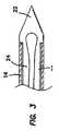
縫合デバイス(suture device)は図1で図解され、参照数字10で呼称される。該デバイスは細長い構造体(elongate structure)であり、その近位の端部のハンドル(handle)12とその遠位の端部の中空シャフト(hollow shaft)14を有する。駆動ロッド(actuating rod)16は該中空シャフト14内に配置され、該ハンドル12から該シャフト14を通るよう延びている。該ハンドル12内では、該駆動ロッド16は親指スライド(thumb slide)18により契合(engaged)されている。その遠位の端部では、該駆動ロッド16は針組立体(needle assembly)20と結合(coupled)されている。この組立体20は鋭利な先端(sharp tip)22と分岐した部分(bifurcated portions)24及び26を有し、該部分は該先端22の近くにスリット又はスロット(slit or slot)28を規定する。 A suturing device is illustrated in FIG. 1 and is designated by the
ハンドル12に対する親指スライド18の操作は、図1に図解する延びた位置(extended position)と、図2及び3に図解する引き込められた位置(retracted position)と、の間で該駆動ロッド16と、取り付けられた針組立体と、を動かす。この特定の実施例では、該ロッド16と針組立体20とを、該引き込められた位置の近位に(proximally)偏倚(bias)させるため、ばね30が使われる。該針組立体20は、該シャフト14の内径より大きい幅だけ離れた肩状停止部(shoulder stops)31を備え得ることは図3を参照すれば気付かれるであろう。これらの肩状停止部31は該針組立体20の遠位の先端22が該引き込められた位置でシャフト14に入るのを防止する。 The operation of the
該分岐した部分24と26は又2つの位置間で移動可能である。第1位置では該分岐した部分24及び26はスロット28を拡大するために半径方向に離される。第2位置では該分岐した部分24及び26はチューブにより近く近接するようもたらされ、該スロット28を閉じる。好ましい実施例では、これらの分岐した部分24及び26は図1に図解される離れた状態に偏倚されるので、該スロット28は該針組立体20が延びた位置にある時は自動的に開く。 The bifurcated
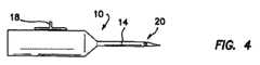
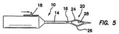
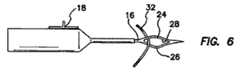
該縫合デバイス10の操作は図4−9で図解される。最初に、弛緩した、貯蔵状態の該デバイス10は図4に図解する引き込められた位置へ偏倚した該針組立体20を有する。該デバイス10に縫合糸32を最初に搭載(load)するために、該針組立体は図5で図解される延びた位置へ動かされねばならない。これは該駆動ロッド16と該針組立体20を遠位の方向に押すよう親指スライド18を遠位の方に押すことにより達成される。該針組立体20が中空シャフト14の遠位の端部を通り抜ける(clears)と、分岐した部分24及び26は自由になり、横方向に延び、それにより図5に図解される様にスロット28を自動的に拡大する。スロット28が拡大されると、縫合糸32は今度は図6で図解される様に該スロットを通過する。親指スライド18のリリースはばね30が駆動ロッド16と針組立体20を引き込められた位置へ近位の方に動くことを可能にする。該針組立体が中空シャフト14内へ引かれると、制限された半径方向寸法(restricted radial dimension)は該分岐した部分24及び26を相互の方へ動くよう強制し、それにより該スロット28を閉じ該縫合糸32と完全に契合する。図7で図解されるこの引き込められた状態では、該デバイスは今や搭載されており、図8で参照数字34で呼称される患者の組織を通る配置用に準備されている。弛緩状態の該デバイスが図8で図解される様に組織34の横断(crossing)で使用するために自動的に配向されるよう駆動ロッド16が引き込められた位置へ偏倚させられることは可能である。 Operation of the
該針組立体20と縫合糸32が組織34を通って延びるに伴い、今や縫合糸を該デバイス10からリリースすることが望まれる。これは、該針組立体を引き込められた位置から延びた位置へ動かすために親指スライドを遠位の方へ再び押すことにより達成される。前の様に、分岐した部分24及び26の偏倚は針組立体20がスロット28を拡大することを可能にさせ、それにより該デバイス10からの縫合糸32のリリースを可能にする。これは図9で図解される。最後の過程として、デバイス10は該組織34から除去され、縫合糸32を組織34を横切って操作可能に配置される様に残す。 As the
この実施例の特定の特徴にも拘わらず、例え該組立体20が引き込められた状態にあっても組織34の通過を可能にする鋭利な先端(sharp point)を該針組立体20が有することを気付くであろう。該分岐した部分24及び26は把持手段(gripping means)として機能し、該手段は縫合糸32を搭載することを可能にするため自動的に開くが、該デバイス10が組織34を通るよう押されると該縫合糸をスロット28内に保持するのに充分な力で閉じられ得る。この場合該中空シャフト14は主として、開き状態と閉じ状態の間で該分岐した部分24及び26を動かすための運搬手段(vehicle)として機能する。図解された実施例では、該中空シャフト14は真っ直ぐな形状を有して示されるが、それは又、種々の解剖的に制限された範囲(anatomically restricted areas)内での利用性(usage)を高めるために多くの種々のカーブした形状(configurations)を備えることも出来る。この機能が、本概念の他の実施例で多くの種々の構造体により達成され得ることは当業者には明らかであろう。 Despite the particular features of this embodiment, the
図10で図解される追加の実施例では、前に論じたそれらと同様な構造体の要素(elements of structure)は小文字”a”が続いた同じ参照数字で呼称される。かくして、この実施例は駆動ロッド16a、針組立体20aそして遠位の先端22aを有する。この場合、しかしながら、該分岐した部分24及び26はそれぞれバッキングアーム(backing arm)36及びギャザリングアーム(gathering arm)38として機能する。該ギャザリングアーム38はスロット28aの遠位の端部では該バッキングアーム36と一体であることが出来るが、該スロット28aの近位の端部では該バッキングアーム36から分離されるのが好ましい。この場所では、該ギャザリングアーム38aは通路40を形成するために該バッキングアーム36aからカットされるが、それは針がカーブを通過する時もっと柔軟になることを可能にする。又該通路40は、もし該通路40が展開時中空シャフト14aの遠位の方へ露出されるなら、縫合糸をスロット28a内へ引くことを容易にする。 In the additional embodiment illustrated in FIG. 10, elements of structure similar to those previously discussed are referred to by the same reference numeral followed by a lowercase letter “a”. Thus, this embodiment has a drive rod 16a, a needle assembly 20a and a distal tip 22a. In this case, however, the branched
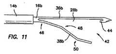
同様な実施例が図11−14で図解されるが、そこでは前に論じられたそれらと同様な構造体の要素は小文字”b”が続いた同じ参照数字で呼称される。この実施例では、該中空シャフト14bは前に論じた仕方で該駆動ロッド16bを受ける。又この実施例は該ギャザリングアーム38bのみならず該バッキングアーム36bを有する。しかしながら、この場合、該ギャザリングアーム38bはスロット28bの近位の端部で該バッキングアーム36bと一体である。該ギャザリングアーム38bは、通路42が縫合糸がスロット28bに入るのを可能にする遠位の端部で該バッキングアーム36bから分離される。この通路42は、アーム44の小さい部分が該遠位の先端22bと共に残るよう該ギャザリングアーム38bに沿ってカットされる。これは針組立体20bが完全に引き込まれた時針組立体が破損無しに縫合糸を保持することを可能にする。この実施例の該ギャザリングアーム38bは種々の方法で形作られ得る。図解された例では、縫合糸の取り込みを容易にするために3つの曲げ(bends)が広い通路42を創る。 Similar embodiments are illustrated in FIGS. 11-14, where elements of structures similar to those previously discussed are designated with the same reference numeral followed by a lowercase “b”. In this embodiment, the
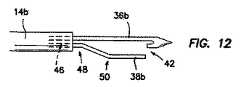
図12で、針組立体20は中空シャフト14b内へ僅かに引き込まれており、曲げ46が概ね真っ直ぐにされる。曲げ50の角度はリップを創り、該リップは該曲げ46が該中空シャフト14bにより真っ直ぐにされる時、該縫合糸をバッキングアーム36bの方へ集める。 In FIG. 12, the
図13で、該針組立体20bはなお更に引き込まれる。これは曲げ48を真っ直ぐにさせ、該ギャザリングアーム38bのバッキングアーム36bとの接触をもたらす一方、該縫合糸用に通路42をなお維持している。 In FIG. 13, the needle assembly 20b is still retracted. This straightens the
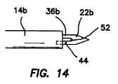
図14に図解する様に完全に引き込まれると、ギャザリングアーム38bの短い部分44は中空シャフト14内に受けられ、該縫合糸を保持する小さい開口部52を残す。 When fully retracted as illustrated in FIG. 14, the
更に進んだ実施例が図15に図解されるが、そこでは上記で論じたそれらと同様な構造体の要素は小文字”c”が続いた同じ参照文字で呼称される。この実施例では、該バッキングアーム36cは又該ギャザリングアーム38cとスロット28cを規定する。この実施例では、該ギャザリングアーム38cは又通路42cを形成するようカットされている。しかしながら、この通路42cを形成する該カットは、該ギャザリングアーム38cの遠位の端部に停止部(stop)54が形成されるように、該針組立体20cの長さと斜め角度(oblique angle)を形成する。この停止部54は該ギャザリングアーム38c上の近位のタング(proximal tang)56と共に形成されるが、該タングは短い部分44上の遠位のタング54と対面(interfaces)する。該ギャザリングアーム38cが該バッキングアーム36cと接触し、それにより取り込んだ縫合糸の自由な動きを制限するのを防止するのがこの停止部54の目的である。 A more advanced embodiment is illustrated in FIG. 15, where elements of structures similar to those discussed above are designated with the same reference letter followed by a lowercase letter “c”. In this embodiment, the
もう1つの実施例が図16,16A及び16Bで図解されるが、そこでは上記で論じたそれらと同様な構造体の要素は小文字”d”が続く同じ参照数字で呼称される。この実施例では、該分岐した部分36dと38dの間に水平スロット28dが形成される。1つの水平スロット28dのみを用いれば、この実施例は図16Aで図解される様な断面を有する。 Another embodiment is illustrated in FIGS. 16, 16A and 16B, where elements of a structure similar to those discussed above are designated with the same reference numeral followed by a lowercase “d”. In this embodiment, a
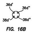
同様な実施例では、垂直スロット60が追加され得て、図16Bの参照数字36d’、36d”、38d’及び38d”により呼称される4つのアームを有する針組立体20dを残すことになる。針組立体20dのこの特定の形状は強烈に曲がったチューブを通る操作を可能にする。勿論どんな数の多数アームもこの利点を実現することが出来る。該アーム36dと38dの近位の端部にはテーパ62が形成され得る。このテーパ付き輪郭は応力集中(stress concentration)を最小化するために針組立体20dの壁を比較的安定的に(consistent)そして柔軟に保つ。 In a similar embodiment, a vertical slot 60 can be added, leaving a needle assembly 20d having four arms designated by
図17は更に進んだ実施例を図解するが、そこでは円柱状針66の周囲(around circumference)に螺旋状スロット(helical slot)64がカットされる。この場合、該螺旋状スロット64は、縫合糸を受けるよう、そしてそれが組織を貫通する時針66内に該縫合糸を隠す(hide)よう適合されている。この特定の実施例では、該螺旋状スロット64はゼロより大きい深さを有するが、好ましくは該針66の半径の0.75倍より大きくないのがよい。 FIG. 17 illustrates a further embodiment, in which a
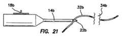
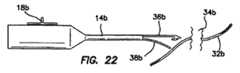
図18−22は針組立体20、特に図11に図解される針組立体20bを使う方法を図解する。 18-22 illustrate a method of using the
図18では、該針組立体20bは引き込められ、中空シャフト14bが組織34bを通過する。縫合糸32bは該組織34bの遠い側に示される。縫合デバイス10bのこの配置を用いて、図19で図解される様に分岐した針組立体20bを展開するために、今度は親指スライド(thumb slide)18bは遠位の方に動かされる。この位置で、該縫合糸32bは遠位の通路42を通り、スロット28b内へ導入される。該親指スライド18bが近位の方へ引かれると、該針組立体20bは図14を参照して論じられた内容(matter)の中空シャフト14b内へ引き込まれる。 In FIG. 18, the needle assembly 20b is retracted and the
図20で図解される、開口部52内に取り込まれた縫合糸を有して、該縫合デバイスは、組織34bから引き込められ(withdrawn)、縫合糸32bが組織34b内に残る針穴(needle hole)を通るよう引く(pulling)。過程のこのステップは図21で図解される。最後に、該親指スライド18bは該針組立体20bを展開するために再び遠位の方へ動かされる。これは該バッキングアーム36bとギャザリングアーム38bの広い分離を生じ、縫合糸32bの該縫合デバイス10bからのリリースに帰着する。この仕方で、縫合糸32bは組織34bを糸通し(threaded through)される。 With the suture captured in the
本発明の更に進んだ実施例が図23で図解されるが、そこでは或る実施例での性能を高めるユニークな形状を有する針組立体20が示される。この場合、針組立体20はバッキングアーム70とギャザリングアーム72を有する。該ギャザリングアーム72は、縫合糸の取り込みを容易化するため最小の針展開(minimal needle deployment)を有する開口部が提供されるようカーブしている。この特徴は、該縫合糸は小さな空間内で契合されねばならず、針は完全には展開され得ない場所での、針組立体20の利用性を高める。 A further embodiment of the present invention is illustrated in FIG. 23, where a
図24では、バッキングアーム70もカーブした同様な実施例が図解されている。この仕方では、針組立体20は中空シャフト14(図1)のそれにより近い形状を提供される。この実施例は、中空シャフトが各々が特定の解剖範囲又は適応(indication)に適合している多くの様々なカーブ形状を有し得て、そしてバッキングアーム70とギャザリングアーム72を有する付随針組立体がそのシャフトの形状にマッチし得ると言う、概念を表している。 FIG. 24 illustrates a similar embodiment in which the
図25及び26は2つの変型(variations)を示すが、そこでは針組立体20はとがった端部(pointed end)76の近位にある太い針セクション(thick needle section)74を有する。これらの実施例では、該太い針セクション74は縫合糸スロット67の部分を規定するが、該部分は、前に注意した様に、種々の形状を有することが出来る。該太いセクション74の近位では、より細いセクション(thinner section)78が創られるよう直径がより小さくされる。この細いセクション78は針が中空シャフト14のカーブを通して動かされることをより容易にする。 FIGS. 25 and 26 show two variations, where the
図27の実施例では、該中空のチューブ63の遠位の端部にノッチ(notch)81が創られる。このノッチ81は、針先端64と連携して、縫合糸を保持する縫合糸スロット83を創る。該ノッチ81が該中空チューブ63内に埋まって、該針先端64はもっと短くされるのでカーブしたデバイスはより低い輪郭(lower profile)を有し、より小さい直径の套管(cannula)内での使用に適合したものとなる。 In the embodiment of FIG. 27, a
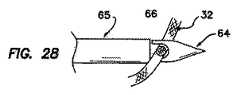
図28及び29は中空チューブ65に対する針先端64の2つの位置を図解する。これらの2つの位置で、縫合糸スロット66の寸法は異なる。図28の縫合糸スロット66は縫合糸を該中空チューブ65に対し容易にスライド又はスリップさせるのに充分な程大きい。比べると、図29の縫合糸スロット66は比較的小さく、何故ならば針先端64が該中空チューブ65内へ僅かに引き込まれたからである。この第2位置で、該針先端64は、該縫合糸スロット66の寸法を減じ、中空チューブ65に対し縫合糸を位置的に保持又はロックするよう引き込められる。図28に図解される第1位置と図29で図解される第2位置の間で種々の引き止め位置(detented positions)を提供するため種々の機構が使用出来る。又図28のスリップ位置(slipping position)と図29のロック位置(locking position)の間で動くために漸進的大きさの力(force of progressive magnitude)を要する機構も提供され得る。 FIGS. 28 and 29 illustrate two positions of the
或る場合には、強烈に曲がった形状を有する中空シャフト14を提供することが有利である。これらの状況下では、もしそれが、展開時又は引き込める時曲げられるべき場所でより細く作られるなら、ニチノール(Nitinol)の様な金属材料で形成された針組立体20が該強烈に曲がったチューブ内でもっと容易にスライドさせられ得る。該針先端の直径がどんな曲げ応力にも耐えるよう充分に太いように、該針組立体20の遠位の端部はより太く(larger)保たれる。近位の端部はより太くされる必要はなく、何故ならそれは展開時及び引き込める時に圧縮/引っ張りでの押し/引きロッドとして主として機能するからである。 In some cases it is advantageous to provide a
図30は多数の形状で提供され得るテーパ付き針の例を示す。一般に遠位の端部で始まり、該針90は遠位のテーパ81を備える。このテーパは、該針先端の僅かに近位の点から該スロットの僅かに近位の場所までの間のどんな場所でスタートすることも出来る。後者の場所では、該スタート位置は該スロットを規定する材料の量を最大化する傾向がある。必要とする強度に依り、近位のテーパ83も又針先端の直径へ戻るよう提供される。この近位のテーパ83は、強度目的でより太いシャフトが必要なところでは特に有利である。 FIG. 30 shows an example of a tapered needle that can be provided in multiple shapes. Beginning generally at the distal end, the
図31で図解される様に、前記実施例の多くは該スロットの遠位の端部に提供されたアール(radius)92から利益を得る。この様なアール92は、スライドする縫合糸が鋭いエッジですり減り(frayed)難いことを保証するだろう。 As illustrated in FIG. 31, many of the embodiments benefit from a
図32の実施例では、これ又針スロットを規定する開口部94がタング96及び98の間に提供される。この開口部94は、針が針チューブから僅かだけ展開された時露出されるように、該スロットに沿いより遠位の場所に規定されるのが好ましい。かくして、針の僅かの展開に於いても、縫合糸は該開口部を通り該スロット内へスライドされ得る。これは縫合糸が該針が組織を出る場所に非常に近い実施例で特に重要になり得る。これらの状況下では、もし針が完全に展開されねばならぬなら該縫合糸を取り込むことはより難しいであろう。スロットに対する開口部94の好ましい遠位の場所であっても、該開口部94が充分に近位に位置付けられ、図33で図解される様にベイスン(basin)96がスロットの近位の端部に形成されることが望ましい。 In the embodiment of FIG. 32, an
図34はその遠位の端部にテーパ103を有する中空チューブハウジング101が提供される実施例を図解する。このテーパ103はそのデバイスに必要な挿入力(insertion force)を最小化する傾向を有するであろう。 FIG. 34 illustrates an embodiment in which a
図1を参照して論じられたハンドル12の好ましい実施例としてハンドル組立体110が図35で図解される。前に論じられた仕方で、ハンドル組立体110は、中空シャフト14とロッド16を有する針組立体20を受けるよう適合されている。加えて、この実施例の針組立体20は、拡大部(enlargement)114と、該拡大部114の近位に配置された円柱状延長部(cylindrical extension)116と、を有するハブ(hub)112を備えている。 A
この実施例では、該ハンドル組立体110はフレーム118と、ユーザーの親指により動かされ得る親指スライド18と、を有する。この仕方で、該親指スライド18は、図35の左方の、後方位置(rearward position)と、図35の右方に図解される前方位置(forward position)と、の間で動かされる得る。 In this embodiment, the
該親指スライド18はスライダー121と針ラッチ(needle latch)123と組み合わされて動くユニットの部分である。該針ラッチ123は該スライダー121上でピボットピン(pivot pin)125の周りに回転可能であり、リーフばね127を有する。又歯130はスライダー121により運ばれ、スロット132及び該フレーム118内のラチェット(ratchet)134と協力(cooperates)する。 The
ロック用レバー(locking lever)136はピボットピン138で該フレーム118上を旋回式に動く(is pivotal)。これは図35に図解されるロック外し位置(unlocking position)とロック位置(locking position)との間で矢印141で示すようにロック用レバー136を移動させる。 A locking
レバーラッチ(lever latch)143はロック用レバー136を図35に図解するロック位置(locking position)でロック(lock)するためにばね145により偏倚される。矢印144に沿うそしてコイルばね145の偏倚に対抗する縦方向のレバーラッチ143の動きは、ロック用レバー136を自由にさせ、コイルばね147の偏倚下で図解されるロック位置からロック外し位置へ動かす。 The
ロック用レバー136がロック外し位置にあると、ハブロック(hub lock)150は該針組立体20のハブ112との接近状態から取り除かれる(removed from proximity with the hub 112)。これは針組立体20の円柱状延長部116を挿入されさせ、ハンドル組立体110の遠位の端部でチャンネル152から除去されさせる。該ハブ112がチャンネル152内へ挿入されると、ロック用レバー136は、ハブロック150が円柱状延長部116内のスロット154と契合するそのロック位置へ動かされる。該レバーラッチ143は自動的に、図35で図解されるロック位置にロック用レバー136を保持する。 When the locking
縫合デバイス10の操作用に最初に準備するために、取り外し可能な針組立体20はハンドル組立体110内に設置されねばならない。論議の目的で、親指スライド18は図35に図解する遠位の位置内へと前方へ押されたと仮定する。 In order to initially prepare for operation of the
設置過程(mounting process)の最初のステップとして、ロック用レバー136がロック外し位置へ、図35の矢印141に沿って下方へ、動かされる。これはレバーラッチ143を後方へ又は図35の左方へ、近位の方へ、動かすことにより達成される。コイルばね145の偏倚に抗する、この動きは該レバーラッチ143にロック用レバー136との契合を外させ、該レバーはコイルばね147の偏倚下でロック外し位置へ自動的に落下する。 As the first step in the mounting process, the locking
ハブロック150がスロット154から引き込められると、針組立体20の円柱状延長部116は針ロッド16と共にチャンネル152内へ動かされる。該針組立体20は挿入されており、拡大部114はハンドル組立体110に対し突き当てられながら、針ロッド16の近位の端部のノッチ155は針ラッチ123と契合する。この点で、ロック用レバー136はばね147の偏倚に対抗して閉じられており、ハブロック150を該円柱状延長部152のスロット154と契合させる。又ロック用レバー136の閉じ作用はリーフばねを通しての正の力(positive force)を提供し、該力は針ラッチ123をノッチ155内に保持する。ロック用レバー136がロック位置へ、上方へ動くと、コイルばね145はレバーラッチ143を偏倚させ、ロック用レバー136と契合し、ロック位置にロックし、保持する。この操作位置で、フレーム118に対する親指スライド18の動きは針ロッド16を針組立体20のハブ114に対して移動させる。 As the
針組立体20をハンドル組立体110内に設置する前記手順は、親指スライド18が前方の、遠位の位置にあると言う仮定で始められる。もしこれがそうでないなら、針ラッチ123は針ロッド16の近位の端部と最初には契合しない。例えこれらの状況下でも、設置操作は前記の仕方で完了するので、ハブ114はロック用レバー136により保持され、該ロック用レバーは翻ってレバーラッチ143によりロックされる。この過程が完了すると、親指スライド18は、針ラッチ123を該ロッド16の近位の端部でノッチ155と契合させるために遠位の方向に前へスライドされる。針ラッチ123によるロッド16のこの契合とロックはリーフばね127の反り(deflection)により適応される。これらの過程の何れかにより、針組立体20はハンドル組立体110と結合され、外科医による使用のため準備される。 The procedure for placing the
操作では、縫合糸32は、針が展開された時該針の分岐した部分24及び26の間に位置付けられる。この点で、針組立体20は親指スライド10及びロッド16を遠位の方へ動かすことにより完全に展開される。針組立体20のこの位置で、縫合糸32は、操作の種々の段階で必要な様に、搭載されるか(loaded)、取り外されるか(unloaded)、取り上げられるか(picked up)、又は落下させられる(dropped off)。 In operation, the
かくして縫合糸32が針組立体20内に搭載されると、外科医はスライダー121の歯130がフレーム118上でスロット132と契合するまで親指スライド18を近位の方へ、後方へ引くことが出来る。この位置で、縫合糸32は針の内部に取り込まれるが、該針のスロット内で横方向に滑るにはなお自由である。該親指スライド18の弾力性(springiness)が歯130をスロット130内に留まらせ、該スロット内で該歯がフレーム118と接触して保持されることを注意しておく。 Thus, once the
もし該縫合糸32と更に契合し、針スロット内で摺動するその能力を除くことが望ましいならば、該親指スライド18は押し下げられ更に引き込められて、歯130に該スロット132を離れさせ、ラチェット134に沿って更に後方へ移動させる。この僅かの運動は針組立体20のロッド16を更に後方へ移動させ、該針組立体20を更に中空シャフト14内へ僅かに引っ張る。この位置で、該縫合糸32は針組立体20内に取り込まれるのみならず、針組立体20と中空シャフト14の間に挟まれ、ロックされる。デバイス10の動作中、この実施例の親指スライド18は更に後方へ動くよう意図されてはいない。 If it is desired to further engage the
それが操作の種々の段階で関心があると、該縫合糸32はこの最も後方の位置から、前方へそして遠位の方へ該親指スライド18を動かすことにより外され(disengaged)得る。もし該親指スライドが押し下げられないなら、該歯130はスロット132内へ落下して戻り、そこで該縫合糸は取り込まれるが、それでも該針穴(needle eye)で滑るのには自由である。この位置で、該縫合糸32は取り除かれ得る。該親指スライド18を押し下げることにより、歯130はスロット132から除去され、該親指スライド18が更に遠位の方向へ動かされることを可能にする。この遠位の運動は針組立体20の分岐した部分24及び26を開き、縫合糸32を完全にリリースする。 If it is of interest at various stages of operation, the
一旦完全な操作手順が完了すると、前に論じた設置過程を逆にすることにより針組立体20はハンドル組立体110から除去され得る。 Once the complete operating procedure is complete, the
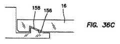
針ロッド16を針ラッチ123とリリース可能に契合させる好ましい構造体が図36A−36Dの連続図で図解されている。これらの図で、ノッチ155は針ロッド16の近位の端部に加工されるランプ(ramp)156を伴って形成される。ハブ112の拡大部114がハンドル組立体110に対抗して突き当たる時、このランプ156は針ロッド16がハンドル組立体110内に押し込まれることを可能にし、該針ロッド16の近位の端部が図36Bで図解される様に針ラッチ123上でランプ158上に乗り上がれる(ride up)。図36Cで図解される様に完全に座ると、このロック機構は、該ランプ158が横に動かされ、ランプ158と付随針ロッド16が遠位に動かされることを可能にするまで、該針組立体がハンドル組立体に取り付けられた儘にする。 A preferred structure for releasably engaging the
針運動の範囲をその引き込まれた位置とその前方位置との間に制限する装置が図37A及び37Bで図解される。この実施例で、ハブ112内の横断スロット(transverse slot)163内の配置用にピン161が提供される。この実施例では、又針組立体20のロッド16は予め決められた長さのチャンネル165を提供される。この部分組立体(sub−assembly)では、該ロッド16は最初に該ハブ12を通して縦方向に延びるよう位置付けられる。該チャンネル165がスロット163と交叉する時、該ピン161は、縦方向に該ハブ112のスロット163を通るよう、そして横断方向にロッド16のチャンネル165を通るよう、挿入される。この部分組立体は図37Bで図解される。この部分組立体により提供される制限された運動は、該針がハンドル内に搭載される位置に常にあるために必要である。この制限された運動の適応性(accomodation)を用いれば、該針はハンドル組立体110内でつかえる(jammed)ことは起こり得ない。 A device that limits the range of needle movement between its retracted position and its forward position is illustrated in FIGS. 37A and 37B. In this embodiment, a
もう1つのユニークな針形状が図38及び39の斜視図で図解される。この実施例で、遠位のスロットは前に論じたそれと同様であるが、その遠位の先端はスロット内へ延びるカット(cut)167により分岐(bifurcated)されている。動作時、該針の展開は分岐した部分169及び170を図39で図解される様に別れ(split)させる。勿論この分岐した形状の多くの変型(variations)がある。2つのこの様な変型が図40と41で図解される。比較によれば、図38のカット167は針先端の軸線に沿うよう配置されるので該先端部分は対称である。図40及び41の図で、カット167は対称な先端部分を作らない。図41と38で該カットは平面状であるが、それにも拘わらず図40ではそれは先端の軸線からオフセットされている。図41の実施例で、該カット167は非平面状である(non−planar)。 Another unique needle shape is illustrated in the perspective views of FIGS. In this embodiment, the distal slot is similar to that previously discussed, but its distal tip is bifurcated by a
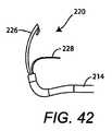
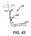
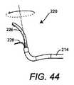
図42−47は、回転制御の特徴(rotational control feature)を提供するアクチュエーター組立体を有する本発明の代わりの実施例に関する。ここで、針組立体は、適当な親指アクチュエーター組立体(thumb actuator assembly)を使って該中空シャフトの近位の端部で駆動ロッド(actuating rod)を操作(manipulating)することにより該中空シャフトの遠位の端部から展開されてもよい。この同じ基本設計を使って、該針組立体が展開された時そのアームも又縫合糸をつかむ(grab)もっと良い位置に入るよう回転される能力が付加される。その時もし望むなら該針組立体は元の位置へ戻るよう回転され、そして引き込め用に該中空シャフト内へ引き戻される。 42-47 relate to an alternative embodiment of the present invention having an actuator assembly that provides a rotational control feature. Here, the needle assembly is operated on the hollow shaft by manipulating the actuating rod at the proximal end of the hollow shaft using a suitable thumb actuator assembly. It may be deployed from the distal end. Using this same basic design, when the needle assembly is deployed, its arm is also grabbed and the ability to be rotated to enter a better position. The needle assembly is then rotated back to its original position, if desired, and pulled back into the hollow shaft for retraction.
図42−44は縫合デバイスの更に進んで可能な実施例の遠位の端部を示すが、該デバイスは針組立体を引き込め、展開することが出来て、そして縫合糸の把持(grasping)に役立つよう展開後該針組立体を種々の望まれる配向へ回転することが出来る。特に、図42−44は、2つのアーム226,228を有する針組立体220が中空シャフト214から展開した後のサンプル回転位置(sample positions of rotation)を示す。図42では、針組立体220は標準の真っ直ぐな位置にある。図43で、針組立体220は矢印により示唆される様に約45°だけ回転され、そして図44で、針組立体220は約135°だけ回転される。又この回転は部分的にだけ展開された針組立体でも起こり得る。 42-44 show the distal end of a further possible embodiment of the suturing device, which can retract and deploy the needle assembly, and grasp the suture. After deployment, the needle assembly can be rotated to various desired orientations to assist. In particular, FIGS. 42-44 illustrate sample positions of rotation after a
該回転動作(rotational action)はユーザーに針組立体220を含む中空シャフト214の近位の端部に適当な制御機構を提供することにより制御される。該針組立体を回転させるためには種々の可能な方法がある。 The rotational action is controlled by providing the user with a suitable control mechanism at the proximal end of the
図45はこの回転性改善(rotational enhancement)を有する縫合デバイス210の1例を示す。特に、図45は、図42−44で示す様に針組立体220を展開し回転させるために親指スライド218を使う縫合デバイス210の第1の実施例の斜視図である。 FIG. 45 shows an example of a
示される様に、ハンドル212は中空シャフト214に取り付けられる。親指ホイール(thumb wheel)218に取り付けられたその近位の端部を有し、その遠位の端部に於いて分割アーム(split arms)226,228で終結(terminates)する駆動ロッド216はシャフト214の長さだけ走っている(Running)。該親指ホイール(thumb wheel)218は、矢印204で示唆される往復運動(reciprocating)により該中空シャフト214に対して分割アーム226,228を展開し、引き込めるよう使われる。又、どんな時でも、該親指ホイール218は矢印205で示唆される様に回転され、該回転は該駆動ロッド216に沿って並進(translates)し、矢印206により示唆される円運動(circular motion)で該針組立体220の分割アーム226,228を動かす。 As shown, handle 212 is attached to
図46a及び46bはレバーチャンネル(lever channel)319内で移動可能な親指レバー(thumb lever)318を有するハンドル312を使うもう1つの実施例を示す。図46bはレバーチャンネル319の頂部の引き伸ばし図(blown−up view)である。該レバー318は、矢印304で表される前後方向(back−and−forth direction)で動かされる時該中空シャフト214から分割アーム226,228を展開し、引き込める。該レバー318は又矢印305で表される左右方向(left−and−right direction)に動くことが出来る。図46bで最も良く見られる様に、該レバー318は、該レバー318がレバーチャンネル319内でより遠位の方に動かされるにつれて左右方向に益々遠く動く(move farther and farther in the left−and−right direction)ことが出来る。その側から側への運動(side−and−side motion)305は該分割アーム226,228の方へ並進し、矢印306により説明される様に実質的に回転運動を創る。該レバー318を近位の方へ引くことにより該分割アーム226,228が引き込められると、レバーチャンネル319内で許される側から側の運動305は、その点で該側から側の運動305がゼロ近くなる近位のスロット311に到達するまで減じられる。該レバーチャンネル319により記述されるテーパーは、該レバー318が遠位の方へ展開される時より多くの側から側の運動305を可能にするので、該分割アーム226,228はそれらが更に進んで展開されるにつれてより多く回転することが出来る306。逆に、レバー318が近位の方へ引かれるにつれて、該側から側の運動305は制限され、該分割アーム226,228が閉鎖間近の位置(near closed position)で過剰応力を受ける(overstressed)ことを防止するのを助ける。近位のスロット311により規定される運動内では、該中空シャフト214に対して規定された位置に該分割アーム226,228を位置付け、保持する1つ以上の引き止め部(detents)又は乗り越え可能な停止部(over−ridable stops)があってもよい。 46a and 46b show another embodiment using a
図47a及び47bは、それらがレバーチャンネル419内で移動可能な親指レバー418を有するハンドル412を使うもう1つの実施例を示す点で図46a及び46bと同様である。しかしながら、ここで、該レバーチャンネル419はレバー418の動きを規定する。これが行われ得る多くの方法があるが、この例では、該レバー418は、中央スロット419aに沿って動かされることにより分割アーム226,228を展開し、引き込めることを可能にされる。遠位の端部で、交叉スロット(cross slot)419bは親指レバー419の側から側の運動(side−to−side motion)を可能にする。又該レバーチャンネル419は、該中空シャフト214に対して規定された場所で該分割アーム226,228をロックするための追加のスロットを有してもよい。図解される実施例では、第1スロットは縫合糸スライド用スロット(suture sliding slot)419cであり、もう1つは縫合糸ロック用スロット(suture locking slot)419dである。該レバー418が該縫合糸スライド用スロット418c内に位置付けられると、取り込まれた縫合糸の自由なスライドを可能にするため該分割アーム226のフックと該中空シャフト214との間に小さなギャップが残される。該レバー418が該縫合糸ロック用スロット419d内に位置付けられると、該ギャップは減じられるので、取り込まれた縫合糸は自由に動くことは出来ない。 47a and 47b are similar to FIGS. 46a and 46b in that they show another embodiment using a
本発明が特定の実施例を参照して論じられたが、論じられた利点を達成するためその概念が別の仕方で具体化され得ることは明らかであろう。 Although the invention has been discussed with reference to specific embodiments, it will be apparent that the concept may be embodied in other ways to achieve the advantages discussed.
Claims (28)
Translated fromJapanese中空の形状を有する細長いシャフトと、
軸線に沿って該シャフトと結合されたハンドル組立体と、
近位の端部と遠位の端部とを有する駆動ロッドと、を具備しており、該駆動ロッドは該ハンドル組立体と該シャフトとの間に延びるよう配置され、細長いシャフトに対して軸方向及び軸線周りに移動し、該デバイスは又、
該駆動ロッドの該近位の端部に動作的に連結された親指アクチュエーター組立体と、
該駆動ロッドの該遠位の端部に配置され、細長いシャフトに対して延びた状態と引き込められた状態との間で、そして該軸線の周りで望まれる角度状態まで、該駆動ロッドと共に移動可能な、針組立体と、
縫合糸スロットを規定する該針組立体の分岐した部分と、を具備しており、該親指アクチュエーター組立体は、縦ハンドルハウジングの遠位の端部近くにて該ハンドル組立体の側方に配置されて該縦ハンドルハウジングの側方から延びており且つ該ハンドル組立体の側方にて遠位の位置と近位の位置との間及び第1の側方位置と第2の側方位置との間で長手方向及び横方向に移動可能であり、
該分岐した部分は、該針組立体が該引き込められた状態にある時は近接した関係を、そして該駆動ロッドが該延びた状態にある時は分かれた関係を有しており、
該針組立体は該引き込められた状態の外科用デバイス弛緩状態へ偏倚されており、そして
該分岐した部分は駆動ロッドが延びた位置にある状態において、該分かれた状態へ偏倚されていることを特徴とする外科用デバイス。A surgical device extending along an axis and having a proximal end and a distal end, wherein the device is operable to move a suture through body tissue, the device comprising:
An elongated shaft having a hollow shape;
A handle assembly coupled to the shaft along an axis;
A drive rod having a proximal end and a distal end, the drive rod being disposed to extend between the handle assembly and the shaft and having an axis relative to the elongated shaftMoving around the direction andaxis , the device also
A thumb actuator assembly operatively coupled to the proximal end of the drive rod;
Located at the distal end of the drive rod and moves with the drive rod between the extended and retracted states relative to the elongate shaft and to the desired angular state about the axis Possible needle assembly;
A bifurcated portion of the needle assembly defining a suture slot, the thumb actuator assembly being disposed laterally of the handle assembly near a distal end of the longitudinal handle housing. Extending laterally of the longitudinal handle housing and laterally of the handle assembly between a distal position and a proximal position and a first lateral position and a second lateral position.Movable longitudinally and laterally between
The bifurcated portion has a close relationship when the needle assembly is in the retracted state and a separate relationship when the drive rod is in the extended state;
The needle assembly is biased to the retracted surgical device relaxed state and the bifurcated portion is biased to the split state with the drive rod in the extended position Surgical device characterized by.
該針組立体内に含まれ、第2縫合糸スロットを規定する第2の分岐した部分を具備することを特徴とする請求項1記載の外科用デバイス。The branched portion is a first branched portion defining a first slot, and the device further comprises:
The surgical device according to claim 1, further comprising a second bifurcated portion included in the needle assembly and defining a second suture slot.
針ハウジング内に自由な縫合糸の状態と取り込まれた縫合糸の状態の間を移動可能な針を有する針組立体と、
縦ハンドルハウジングを有するハンドル組立体と、
遠位の位置と近位の位置の間で、そして第1の側方位置と第2の側方位置の間で該縦ハンドルハウジング上で軸方向及び軸線周りに移動可能な、親指アクチュエーター組立体と、を具備しており、
該親指アクチュエーター組立体は、該縦ハンドルハウジングの遠位の端部近くにて該ハンドル組立体の側部に配置されて該縦ハンドルハウジングの側部から延びており且つ該ハンドル組立体の側部にて遠位の位置と近位の位置との間及び第1の側方位置と第2の側方位置との間で軸方向及び軸線周りに移動可能であり、
該親指アクチュエーター組立体の該遠位の位置は該自由な縫合糸の状態の該針と組み合わされ、
該親指アクチュエーター組立体の該近位の位置は該取り込まれた縫合糸の状態の該針と組み合わされ、
該親指アクチュエーター組立体の該第1の側方位置は第1角度位置の該針と組み合わされ、そして
該親指アクチュエーター組立体の該第2の側方位置は第2角度位置の該針と組み合わされることを特徴とする外科用縫合デバイス。In a surgical suturing device, a needle assembly having a needle that is movable between a free suture state and a captured suture state within a needle housing;
A handle assembly having a vertical handle housing;
Thumb actuator assembly movableaxially and about an axis on the longitudinal handle housing between a distal position and a proximal position and between a first lateral position and a second lateral position And,
The thumb actuator assembly is disposed on a side of thehandle assembly near a distal end of the vertical handle housing and extends from a side of the vertical handle housing and is a side of thehandle assembly. Movable axiallyand about an axis between a distal position and a proximal position and between a first lateral position and a second lateral position at
The distal position of the thumb actuator assembly is combined with the needle in the free suture state;
The proximal position of the thumb actuator assembly is combined with the needle in the captured suture state;
The first lateral position of the thumb actuator assembly is combined with the needle in a first angular position, and the second lateral position of the thumb actuator assembly is combined with the needle in a second angular position. Surgical suturing device.
該親指スライド組立体の該近位の位置が該ロックされた縫合糸の状態の該針と組み合わされることを特徴とする請求項25記載の外科用縫合デバイス。The needle is movable within the needle housing between a free suture state, a captured suture state, and a locked suture state;
26. The surgical suturing device of claim 25, wherein the proximal position of the thumb slide assembly is combined with the needle in the locked suture state.
Applications Claiming Priority (3)
| Application Number | Priority Date | Filing Date | Title |
|---|---|---|---|
| US60424304P | 2004-08-24 | 2004-08-24 | |
| US60/604,243 | 2004-08-24 | ||
| PCT/US2005/030107WO2006023975A2 (en) | 2004-08-24 | 2005-08-24 | Expandable needle suture apparatus and associated handle assembly with rotational suture manipulation system |
Publications (2)
| Publication Number | Publication Date |
|---|---|
| JP2008538510A JP2008538510A (en) | 2008-10-30 |
| JP5232471B2true JP5232471B2 (en) | 2013-07-10 |
Family
ID=35968316
Family Applications (1)
| Application Number | Title | Priority Date | Filing Date |
|---|---|---|---|
| JP2007530085AExpired - LifetimeJP5232471B2 (en) | 2004-08-24 | 2005-08-24 | Deployable needle suturing device and associated handle assembly with suture rotation operation system |
Country Status (6)
| Country | Link |
|---|---|
| EP (2) | EP3326543B1 (en) |
| JP (1) | JP5232471B2 (en) |
| AU (2) | AU2005277073A1 (en) |
| CA (1) | CA2578197C (en) |
| IL (1) | IL181420A (en) |
| WO (1) | WO2006023975A2 (en) |
Families Citing this family (22)
| Publication number | Priority date | Publication date | Assignee | Title |
|---|---|---|---|---|
| JP5010178B2 (en) | 2006-05-30 | 2012-08-29 | 昌貴 鮒田 | Medical instruments |
| US20080086147A1 (en)* | 2006-10-05 | 2008-04-10 | Knapp Thomas P | Shape memory filament for suture management |
| US9072514B2 (en) | 2006-10-05 | 2015-07-07 | Thomas P. Knapp | Shape memory filament for suture management |
| US8556916B2 (en)* | 2011-02-14 | 2013-10-15 | Smith & Nephew, Inc. | Method and device for suture manipulation |
| JP6158801B2 (en) | 2011-07-15 | 2017-07-05 | ニューサート サイエンシーズ, インコーポレイテッド | Compositions and methods for modulating metabolic pathways |
| US9451951B2 (en) | 2012-11-07 | 2016-09-27 | Arthrex, Inc. | Suture snare with retractable sleeve |
| MX2015006023A (en) | 2012-11-13 | 2016-03-31 | Nusirt Sciences Inc | Compositions and methods for increasing energy metabolism. |
| CA2914577C (en) | 2013-07-15 | 2018-04-10 | Cook Medical Technologies Llc | Suture passer and method of operating same |
| CN106456155A (en) | 2014-04-24 | 2017-02-22 | 史密夫和内修有限公司 | Suture passer |
| JP6682763B2 (en)* | 2015-02-03 | 2020-04-15 | 日本ゼオン株式会社 | Endoscope treatment tool |
| CA3029304C (en) | 2016-06-30 | 2023-03-14 | Dongbang Medical Co., Ltd. | Lifting member |
| US10898181B2 (en) | 2017-03-17 | 2021-01-26 | Cypris Medical, Inc. | Suturing system |
| US10709440B2 (en)* | 2017-06-29 | 2020-07-14 | Ethicon Llc | Suture passing instrument with puncture site identification feature |
| US10660637B2 (en)* | 2018-04-06 | 2020-05-26 | Cypris Medical, Inc. | Suturing system |
| US11278274B2 (en) | 2018-05-04 | 2022-03-22 | Arch Day Design, Llc | Suture passing device |
| EP3787526B1 (en) | 2018-05-04 | 2023-04-19 | Arch Day Design, LLC | Suture passing device |
| US11583269B2 (en) | 2018-05-04 | 2023-02-21 | Arch Day Design, Llc | Suture passing device |
| US11033261B2 (en) | 2018-05-31 | 2021-06-15 | Cypris Medical, Inc. | Suture system |
| US11064995B2 (en)* | 2019-05-02 | 2021-07-20 | Arthrex, Inc. | Surgical device with trigger operated needle |
| US11246586B2 (en) | 2019-08-20 | 2022-02-15 | Arch Day Design, Llc | Instrument to manipulate and pass suture |
| US12137899B2 (en) | 2020-05-11 | 2024-11-12 | Cypris Medical, Inc. | Multiple suture placement system |
| EP4433129A1 (en) | 2022-01-04 | 2024-09-25 | TACC Inc | Vascular access line and implantation devices and methods |
Family Cites Families (15)
| Publication number | Priority date | Publication date | Assignee | Title |
|---|---|---|---|---|
| US5312422A (en)* | 1992-07-16 | 1994-05-17 | Linvatec Corporation | Endoscopic suturing needle |
| US5281237A (en)* | 1992-09-25 | 1994-01-25 | Gimpelson Richard J | Surgical stitching device and method of use |
| US5618290A (en)* | 1993-10-19 | 1997-04-08 | W.L. Gore & Associates, Inc. | Endoscopic suture passer and method |
| US5573542A (en)* | 1994-08-17 | 1996-11-12 | Tahoe Surgical Instruments-Puerto Rico | Endoscopic suture placement tool |
| US5499991A (en)* | 1994-12-19 | 1996-03-19 | Linvatec Corporation | Endoscopic needle with suture retriever |
| US5653716A (en)* | 1994-12-29 | 1997-08-05 | Acufex Microsurgical, Inc. | Suture manipulating instrument with grasping members |
| US5817111A (en)* | 1996-03-28 | 1998-10-06 | Riza; Erol D. | Open loop suture snare |
| JPH10192288A (en)* | 1997-01-10 | 1998-07-28 | Yuichi Matsuzawa | Method and device for suture for operation |
| US6352539B1 (en)* | 1997-05-02 | 2002-03-05 | Scilogy Corp. | Surgical instrument with rotatable shaft |
| US5910148A (en)* | 1997-08-06 | 1999-06-08 | Mitek Surgical Products, Inc. | Suture retrograder |
| US6077277A (en)* | 1999-04-05 | 2000-06-20 | Starion Instruments, Inc. | Suture welding device |
| US6723107B1 (en)* | 1999-04-19 | 2004-04-20 | Orthopaedic Biosystems Ltd. | Method and apparatus for suturing |
| US7842050B2 (en)* | 2001-02-26 | 2010-11-30 | Diduch David R | Suture passing devices |
| US6936054B2 (en)* | 2002-07-22 | 2005-08-30 | Boston Scientific Scimed, Inc. | Placing sutures |
| CA2404564A1 (en)* | 2002-09-23 | 2004-03-23 | Yu-Chung Chang | Hemostasis straight needle for hepatic resection |
- 2005
- 2005-08-24EPEP17194609.8Apatent/EP3326543B1/ennot_activeExpired - Lifetime
- 2005-08-24CACA2578197Apatent/CA2578197C/ennot_activeExpired - Fee Related
- 2005-08-24AUAU2005277073Apatent/AU2005277073A1/ennot_activeAbandoned
- 2005-08-24JPJP2007530085Apatent/JP5232471B2/ennot_activeExpired - Lifetime
- 2005-08-24EPEP05788810.9Apatent/EP1799121B1/ennot_activeExpired - Lifetime
- 2005-08-24WOPCT/US2005/030107patent/WO2006023975A2/enactiveApplication Filing
- 2007
- 2007-02-19ILIL181420Apatent/IL181420A/enactiveIP Right Grant
- 2010
- 2010-07-20AUAU2010203081Apatent/AU2010203081B2/ennot_activeCeased
Also Published As
| Publication number | Publication date |
|---|---|
| CA2578197C (en) | 2010-06-29 |
| EP1799121A2 (en) | 2007-06-27 |
| JP2008538510A (en) | 2008-10-30 |
| AU2010203081A1 (en) | 2010-08-12 |
| EP3326543B1 (en) | 2019-07-24 |
| AU2010203081B2 (en) | 2011-08-25 |
| WO2006023975A2 (en) | 2006-03-02 |
| IL181420A0 (en) | 2007-07-04 |
| EP1799121A4 (en) | 2011-05-04 |
| CA2578197A1 (en) | 2006-03-02 |
| IL181420A (en) | 2013-09-30 |
| EP1799121B1 (en) | 2017-10-04 |
| AU2005277073A1 (en) | 2006-03-02 |
| EP3326543A1 (en) | 2018-05-30 |
| WO2006023975A3 (en) | 2009-04-16 |
Similar Documents
| Publication | Publication Date | Title |
|---|---|---|
| JP5232471B2 (en) | Deployable needle suturing device and associated handle assembly with suture rotation operation system | |
| US10743861B2 (en) | Expandable needle suture apparatus and associated handle assembly with rotational suture manipulation system | |
| AU2004222262B2 (en) | Expandable needle suture apparatus and associated handle assembly | |
| EP1274351B1 (en) | Apparatus for suturing | |
| US11083364B2 (en) | Endoscopic tissue grasping systems and methods | |
| US20050234479A1 (en) | Suture passing surgical instrument | |
| AU2001253899A1 (en) | Method and apparatus for suturing | |
| US20240415377A1 (en) | Endoscopic tissue grasping systems and methods | |
| AU2005234698B2 (en) | Method and apparatus for suturing |
Legal Events
| Date | Code | Title | Description |
|---|---|---|---|
| A621 | Written request for application examination | Free format text:JAPANESE INTERMEDIATE CODE: A621 Effective date:20080807 | |
| RD02 | Notification of acceptance of power of attorney | Free format text:JAPANESE INTERMEDIATE CODE: A7422 Effective date:20081201 | |
| A521 | Request for written amendment filed | Free format text:JAPANESE INTERMEDIATE CODE: A821 Effective date:20081201 | |
| A131 | Notification of reasons for refusal | Free format text:JAPANESE INTERMEDIATE CODE: A131 Effective date:20110405 | |
| A601 | Written request for extension of time | Free format text:JAPANESE INTERMEDIATE CODE: A601 Effective date:20110701 | |
| A602 | Written permission of extension of time | Free format text:JAPANESE INTERMEDIATE CODE: A602 Effective date:20110708 | |
| A601 | Written request for extension of time | Free format text:JAPANESE INTERMEDIATE CODE: A601 Effective date:20110804 | |
| A602 | Written permission of extension of time | Free format text:JAPANESE INTERMEDIATE CODE: A602 Effective date:20110815 | |
| A601 | Written request for extension of time | Free format text:JAPANESE INTERMEDIATE CODE: A601 Effective date:20110825 | |
| A602 | Written permission of extension of time | Free format text:JAPANESE INTERMEDIATE CODE: A602 Effective date:20110901 | |
| A521 | Request for written amendment filed | Free format text:JAPANESE INTERMEDIATE CODE: A523 Effective date:20111004 | |
| A131 | Notification of reasons for refusal | Free format text:JAPANESE INTERMEDIATE CODE: A131 Effective date:20120508 | |
| A601 | Written request for extension of time | Free format text:JAPANESE INTERMEDIATE CODE: A601 Effective date:20120807 | |
| A602 | Written permission of extension of time | Free format text:JAPANESE INTERMEDIATE CODE: A602 Effective date:20120814 | |
| A601 | Written request for extension of time | Free format text:JAPANESE INTERMEDIATE CODE: A601 Effective date:20120903 | |
| A602 | Written permission of extension of time | Free format text:JAPANESE INTERMEDIATE CODE: A602 Effective date:20120910 | |
| A601 | Written request for extension of time | Free format text:JAPANESE INTERMEDIATE CODE: A601 Effective date:20121004 | |
| A602 | Written permission of extension of time | Free format text:JAPANESE INTERMEDIATE CODE: A602 Effective date:20121012 | |
| A521 | Request for written amendment filed | Free format text:JAPANESE INTERMEDIATE CODE: A523 Effective date:20121108 | |
| A131 | Notification of reasons for refusal | Free format text:JAPANESE INTERMEDIATE CODE: A131 Effective date:20130129 | |
| A521 | Request for written amendment filed | Free format text:JAPANESE INTERMEDIATE CODE: A523 Effective date:20130213 | |
| TRDD | Decision of grant or rejection written | ||
| A01 | Written decision to grant a patent or to grant a registration (utility model) | Free format text:JAPANESE INTERMEDIATE CODE: A01 Effective date:20130319 | |
| A61 | First payment of annual fees (during grant procedure) | Free format text:JAPANESE INTERMEDIATE CODE: A61 Effective date:20130325 | |
| FPAY | Renewal fee payment (event date is renewal date of database) | Free format text:PAYMENT UNTIL: 20160329 Year of fee payment:3 | |
| R150 | Certificate of patent or registration of utility model | Free format text:JAPANESE INTERMEDIATE CODE: R150 | |
| R250 | Receipt of annual fees | Free format text:JAPANESE INTERMEDIATE CODE: R250 | |
| R250 | Receipt of annual fees | Free format text:JAPANESE INTERMEDIATE CODE: R250 | |
| R250 | Receipt of annual fees | Free format text:JAPANESE INTERMEDIATE CODE: R250 | |
| R250 | Receipt of annual fees | Free format text:JAPANESE INTERMEDIATE CODE: R250 |