JP5231671B1 - Fitting and ferrule manufacturing method thereof - Google Patents
Fitting and ferrule manufacturing method thereofDownload PDFInfo
- Publication number
- JP5231671B1 JP5231671B1JP2012169271AJP2012169271AJP5231671B1JP 5231671 B1JP5231671 B1JP 5231671B1JP 2012169271 AJP2012169271 AJP 2012169271AJP 2012169271 AJP2012169271 AJP 2012169271AJP 5231671 B1JP5231671 B1JP 5231671B1
- Authority
- JP
- Japan
- Prior art keywords
- ferrule
- peripheral surface
- tube
- end portion
- rising
- Prior art date
- Legal status (The legal status is an assumption and is not a legal conclusion. Google has not performed a legal analysis and makes no representation as to the accuracy of the status listed.)
- Active
Links
Images


Classifications
- F—MECHANICAL ENGINEERING; LIGHTING; HEATING; WEAPONS; BLASTING
- F16—ENGINEERING ELEMENTS AND UNITS; GENERAL MEASURES FOR PRODUCING AND MAINTAINING EFFECTIVE FUNCTIONING OF MACHINES OR INSTALLATIONS; THERMAL INSULATION IN GENERAL
- F16L—PIPES; JOINTS OR FITTINGS FOR PIPES; SUPPORTS FOR PIPES, CABLES OR PROTECTIVE TUBING; MEANS FOR THERMAL INSULATION IN GENERAL
- F16L19/00—Joints in which sealing surfaces are pressed together by means of a member, e.g. a swivel nut, screwed on, or into, one of the joint parts
- F16L19/08—Joints in which sealing surfaces are pressed together by means of a member, e.g. a swivel nut, screwed on, or into, one of the joint parts with metal rings which bite into the wall of the pipe
- F16L19/10—Joints in which sealing surfaces are pressed together by means of a member, e.g. a swivel nut, screwed on, or into, one of the joint parts with metal rings which bite into the wall of the pipe the profile of the ring being altered
- B—PERFORMING OPERATIONS; TRANSPORTING
- B21—MECHANICAL METAL-WORKING WITHOUT ESSENTIALLY REMOVING MATERIAL; PUNCHING METAL
- B21D—WORKING OR PROCESSING OF SHEET METAL OR METAL TUBES, RODS OR PROFILES WITHOUT ESSENTIALLY REMOVING MATERIAL; PUNCHING METAL
- B21D41/00—Application of procedures in order to alter the diameter of tube ends
- B21D41/04—Reducing; Closing
- B—PERFORMING OPERATIONS; TRANSPORTING
- B21—MECHANICAL METAL-WORKING WITHOUT ESSENTIALLY REMOVING MATERIAL; PUNCHING METAL
- B21D—WORKING OR PROCESSING OF SHEET METAL OR METAL TUBES, RODS OR PROFILES WITHOUT ESSENTIALLY REMOVING MATERIAL; PUNCHING METAL
- B21D53/00—Making other particular articles
- B21D53/16—Making other particular articles rings, e.g. barrel hoops
- Y—GENERAL TAGGING OF NEW TECHNOLOGICAL DEVELOPMENTS; GENERAL TAGGING OF CROSS-SECTIONAL TECHNOLOGIES SPANNING OVER SEVERAL SECTIONS OF THE IPC; TECHNICAL SUBJECTS COVERED BY FORMER USPC CROSS-REFERENCE ART COLLECTIONS [XRACs] AND DIGESTS
- Y10—TECHNICAL SUBJECTS COVERED BY FORMER USPC
- Y10T—TECHNICAL SUBJECTS COVERED BY FORMER US CLASSIFICATION
- Y10T29/00—Metal working
- Y10T29/49—Method of mechanical manufacture
- Y10T29/49428—Gas and water specific plumbing component making
- Y10T29/49446—Ferrule making or reforming
Landscapes
- Engineering & Computer Science (AREA)
- Mechanical Engineering (AREA)
- General Engineering & Computer Science (AREA)
- Joints With Pressure Members (AREA)
- Turning (AREA)
- Joints With Sleeves (AREA)
Abstract
Translated fromJapaneseDescription
Translated fromJapanese本発明は、流体を通す流体管などの管の接続に用いられる継手に関する。 The present invention relates to a joint used for connecting a pipe such as a fluid pipe through which a fluid passes.
流体管の接続において、小さい締め付けトルクで高いシール性が得られる継手としてダブルフェルールタイプ継手がある(特許文献1、2参照)。 There is a double ferrule-type joint as a joint that can obtain high sealing performance with a small tightening torque in connection of fluid pipes (see Patent Documents 1 and 2).
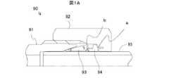
図1A〜図1Cは、一般的なダブルフェルールタイプ継手について説明するための図である。図1Aを参照すると、ダブルフェルールタイプ継手90は、継手本体91、ナット92、フロントフェルール93、およびバックフェルール94で構成されている。 1A to 1C are diagrams for explaining a general double ferrule-type joint. Referring to FIG. 1A, the double ferrule-
継手本体91とナット92はネジ結合される。ネジ結合を締め込むと、図1Aに示すように、ナット92がバックフェルール94を押す(図中のa点)。ナット92に押されたバックフェルール94は、図1Bに示すように、フロントフェルール93の下に入り込みながらフロントフェルール93を押す(図中のb点)。フロントフェルール93は、バックフェルール94が下に入り込むことにより後端を上げるように回転して立ち上がりながら、継手本体91のテーパ面に沿って先端を管95に食い込ませる(図中のc点)。 The
このとき、図1Cに示すように、フロントフェルール93がb点を力点とし、d点を支点として立ち上がることにより、作用点となるc点で強い食い込み力が発生し、良好なシール機構が実現される。 At this time, as shown in FIG. 1C, when the
このようなダブルフェルールタイプ継手90によれば高いシール性により流体の漏れを実質的に防止することができる。 According to such a double ferrule-
その一方で、部品点数の削減によるコストダウンや取り付け作業の容易化を図るために様々なシングルフェールールタイプ継手も提案されている(特許文献3〜5参照)。シングルフェルールタイプ継手は、フェルールが単一の継手であり、継手本体、ナット、およびフェルールで構成されている。ネジ結合の締め込みでナットに押されたフェルールが継手本体のテーパ面に沿って先端を管に食い込ませることにより、シール機構を実現する。継手本体とナットとの間に配置するフェルールを1つにすることで、部品点数が削減され、取り付け作業も簡略化される。 On the other hand, various single ferrule type joints have also been proposed in order to reduce costs by reducing the number of parts and to facilitate installation work (see Patent Documents 3 to 5). In the single ferrule type joint, the ferrule is a single joint and includes a joint body, a nut, and a ferrule. The ferrule pushed by the nut by tightening the screw connection causes the tip to bite into the pipe along the tapered surface of the joint body, thereby realizing a seal mechanism. By using one ferrule between the joint body and the nut, the number of parts can be reduced, and the installation work can be simplified.
これらシングルフェエルールタイプ継手は、ナットがフェルールを軸方向に押す力から、フェルールの先端を径方向内向きに管に食い込ませる力を得るものである。単一のフェルールの形状を工夫することにより力の方向を軸方向から径方向内向きに変換している。 These single ferrule-type joints obtain force that causes the tip of the ferrule to bite into the pipe radially inward from the force with which the nut pushes the ferrule in the axial direction. By devising the shape of a single ferrule, the direction of force is changed from the axial direction to the radially inward direction.
しかしながら、ダブルフェルールタイプ継手では、バックフェルール94がフロントフェルール93の下に入り込むことでフロントフェルール93がb点を力点としd点を支点として立ち上がるのと異なり、シングルフェルールタイプ継手では、単一のフェルールの形状によって力の方向を変化させるので、概して管の先端において径方向内向きの力を効率良く発生させることができない。 However, in the double ferrule type joint, the
また、特許文献6にはシングルフェルールタイプ継手の特徴について様々な考察が述べられている。 Patent Document 6 describes various considerations about the characteristics of the single ferrule-type joint.
上述のように、ダブルフェルールタイプ継手はフェルールの先端を管に食い込ませる力を効率良く得られる一方で部品点数が多くなっており、逆に、シングルフェルールタイプ継手は部品点数が少なくなっている一方でフェルールの先端を管に食い込ませる力を効率良く得られない。このように、ダブルフェルールタイプ継手とシングルフェルールタイプ継手には一長一短がある。 As described above, the double ferrule-type joint can efficiently obtain the force to bite the tip of the ferrule into the pipe, while the number of parts is large, and conversely, the single ferrule-type joint has a small number of parts. Therefore, the force to bite the ferrule tip into the tube cannot be obtained efficiently. Thus, the double ferrule type joint and the single ferrule type joint have advantages and disadvantages.
本発明の目的は、少ない部品点数で、フェルールの端部を管に向けて食い込み駆動する力を効率良く発生させることを可能にする技術を提供することである。 An object of the present invention is to provide a technique that can efficiently generate a force for driving an end of a ferrule toward a pipe with a small number of parts.
本発明の一つの実施態様に従う継手は、管と接続する継手であって、前記管を受け入れる貫通孔を有する第1部材と、前記管を受け入れる貫通孔を有し、該貫通孔の中心軸を前記第1部材の貫通孔の中心軸と一致させて前記第1部材とネジ結合する第2部材と、前記管を受け入れる第1端部から第2端部まで通ずる貫通孔を有し、前記第1端部と前記第2端部の間に前記第1端部および前記第2端部よりも内径が大きい部分があり、該貫通孔の中心軸を前記第1部材および前記第2部材の中心軸と一致させて、前記第1部材の内周面と前記第2部材の内周面と前記管の外周面とで形成される収納空間に配置されるフェルールと、を有し、前記フェルールには、前記第1端部を含む立ち上がり部と、前記立ち上がり部よりも前記第2端部側にある被押圧部と、前記第1端部および前記第2端部よりも内径が大きい部分を含み前記立ち上がり部と前記被押圧部を接続する中間部とがあり、前記第1部材には、前記フェルールの前記第1端部に当接するテーパ形状の内周面である第1テーパ内周面があり、前記第2部材には、前記フェルールの前記被押圧部の少なくとも一部を押圧する押圧部があり、前記収納空間には、前記フェルールを収納して前記立ち上がり部を前記管の外周面とのなす角を増大させるように立ち上げることができる第1の許容空間がある。 A joint according to one embodiment of the present invention is a joint that is connected to a pipe, and includes a first member having a through hole that receives the pipe, a through hole that receives the pipe, and a central axis of the through hole. A second member threadedly coupled to the first member so as to coincide with a central axis of the through hole of the first member; a through hole communicating from the first end portion receiving the tube to the second end portion; There is a portion having an inner diameter larger than the first end and the second end between one end and the second end, and the center axis of the through hole is the center of the first member and the second member. A ferrule disposed in a storage space formed by an inner peripheral surface of the first member, an inner peripheral surface of the second member, and an outer peripheral surface of the pipe, in alignment with an axis, and the ferrule Is a rising portion including the first end portion and closer to the second end portion than the rising portion. There is a pressed portion, and an intermediate portion that includes a portion having an inner diameter larger than that of the first end portion and the second end portion and connects the rising portion and the pressed portion, and the first member includes the ferrule There is a first tapered inner peripheral surface that is a tapered inner peripheral surface that contacts the first end portion, and the second member has a pressing portion that presses at least a part of the pressed portion of the ferrule. In the storage space, there is a first allowable space in which the ferrule can be stored and the rising portion can be raised so as to increase an angle formed by the outer peripheral surface of the pipe.
本発明によれば、シングルフェルール構成により少ない部品点数で、フェルールの端部を管に向けて食い込み駆動する力を効率良く発生させることが可能となる。 According to the present invention, it is possible to efficiently generate a force for driving the end portion of the ferrule toward the pipe with a small number of parts by the single ferrule configuration.
本発明の実施形態の一例を以下に図面を参照して説明する。 An example of an embodiment of the present invention will be described below with reference to the drawings.
図2は、本実施形態による継手の断面図である。図2を参照すると、継手10は、継手本体11、ナット12、およびフェルール13を有している。継手は流体を通す管と管とを接続する等の目的で、管と接続して使用される。 FIG. 2 is a cross-sectional view of the joint according to the present embodiment. Referring to FIG. 2, the
継手本体11とナット12はネジ結合され、締め込んだり、緩めたりすることができる。継手本体11、ナット12、およびフェルール13には、管95を受け入れる貫通孔がある。継手10は、継手本体11の内周面と、ナット12の内周面と、管95の外周面で形成される収納空間にフェルール13を収容するように、ナット12、フェルール13、継手本体11の順番に管95を受け入れ、継手本体11とナット12のネジ結合を締め込むと、管95に接続される。 The
フェルール13は、前方端部(第1端部)13aから後方端部(第2端部)13bまでの間に立ち上がり部13c、中間部13e、および被押圧部13dを有している。ここでは継手本体11側を前方とし、ナット12側を後方としている。 The
フェルールの前方端部13aと後方端部13bの間に前方端部13aおよび後方端部13bよりも内径が大きい領域がある。立ち上がり部13cは前方端部13aを含み、後方に向けて徐々に内径および外径が増大する領域である。被押圧部13dは後方端部13bを含み、後方に向けて徐々に内径および外径が縮小する領域である。中間部13eは、立ち上がり部13cと被押圧部13dの間の領域であり、最も内径の大きい部分を含んでいる。 There is a region having a larger inner diameter than the
継手本体11には、フェルール13の前方端部13aに当接するテーパ形状の内周面であるテーパ内周面11aがある。テーパ内周面11aとフェルール13の立ち上がり部13cの外周面とは中心軸を通る平面上で所体の角度βをなしている。 The
ナット12には、フェルール13の被押圧部13dの少なくとも一部を押圧する押圧部12aがある。 The
押圧部12aには、フェルール13の後方端部13bに当接するテーパ形状の内周面であるテーパ内周面がある。テーパ内周面とフェルール13の被押圧部13dとは中心軸を通る平面上で所定の角度αをなしている。なお、αおよびβは、フェルール13の厚さ、中間部13eの長さ、被押圧部13dの形状、ナット12の押圧部12aの形状など様々なパラメータの設定値に応じて適切な値に設定すればよい。 The
継手本体11とナット12がフィンガータイトの状態では、収納空間には、フェルール13を収納して、更に、中間部13eの外径を増大させ、立ち上がり部13cを管95の外周面とのなす角を増大させるように(角度βを縮小させるように)、立ち上げることができるだけの許容空間15がある。フィンガータイトの状態は、継手本体11とフェルール13、フェルール13とナット12がそれぞれ当接しているがフェルール11の変形は生じない程度まで継手本体11とフェルール13のネジ結合を締め込んだ状態である。 When the
なお、本実施形態では、一例として、許容空間15として、立ち上がり部13cを管95の外周面とのなす角を増大させるように立ち上げることができる第1の許容空間15aと、立ち上がり部13cを立ち上げるために中間部13eの外径を増大させるための第2の許容空間15bの2つの空間がある例を示している。第1の許容空間15aは立ち上がり部13cの外側(図2中の上方)にある空間であり、第2の許容空間15bは中間部13eの外側(図2中の上方)にある空間である。しかしながら、本発明がこの例に限定されることは無い。他の例として、第1の許容空間15aはあるが第2の許容空間15bは無く、それでも、第1の許容空間15aがあるが故に立ち上がり部13cの立ち上がりが可能な継手であっても良い。 In the present embodiment, as an example, the
ナット12、フェルール13、および継手本体11の中心軸を一致させ、ナット12、フェルール13、継手本体11の順番に管95を受け入れ、フィンガータイトの状態から、継手本体11とナット12のネジ結合を所定の締め付けトルクで所定の締め付け量だけ締め込むと、フェルール13の前方端部13aが管95に食い込んでシールをなし、継手10が管95と接続される。 The central axes of the
本実施形態によれば、フェルール13の中間部13eに内周の大きい部分があるので、ナット12に押されたフェルール13は、継手本体11に突き当たったまま中間部13eを外側に膨らませ、立ち上がり部13cが立ち上がる。フェルール13の立ち上がり部13cが立ち上がるとき、その前方端部13aの外周が、継手本体11のテーパ内周面11aに当接して進行が制限されるので、管95に当接する前方端部13aの内周部が管95に食い込むように駆動される力が効率良く発生し、継手10がシール性の得られる状態で管95に接続される。 According to the present embodiment, since the
以下、継手10を管95に組み付けるときの各部の動作および作用について更に説明する。図3は、継手を管に組み付けるときの各部の動作および作用について説明するための図である。 Hereinafter, the operation and action of each part when the joint 10 is assembled to the
図3を参照し、継手本体11とナット12のネジ結合を締め込むと、軸方向に発生する力F1によってナット12の押圧部12aがフェルール13の被押圧部13dを前方に押す。被押圧部13dを押されたフェルール13は、それに伴って前方の継手本体11を前方に押す。そして、その反作用として、継手本体11がフェルール13を後方に押す。 Referring to FIG. 3, when the screw connection between the
前方端部13aを後方に押され、後方端部13bを前方に押されたフェルール13は、力F1から派生した力F2により中間部13eの内径および外径を増大させ、前方端部13aと後方端部13bが接近するように変形する。このときに、立ち上がり部13cは、その外周面の角度が継手本体11のテーパ内周面11aの角度と一致するまで、管95の外周とのなす角を増大させるように立ち上がる。 The
立ち上がり部13cが立ち上がることで、前方端部13aでは、継手本体11のテーパ内周面11aに当接する外周部がテーパ内周面11aによって制限され、管95に当接する内周部が管に食い込むように駆動される。つまり、フェルール13の前方端部13aでは、外周部が支点となり、内周部が作用点となって、テコの原理により強い力でフェルール13が管95に向けて食い込み駆動される。 As the rising
また、変形したフェルール13には、元の形状に戻ろうとする弾性力がある程度は残るので、フェルール13と継手本体11とが押し合い、またフェルール13とナット12とが押し合う状態となる。その結果、振動などによる継手10が管95から緩んでしまうのを抑制することができる。また、フェルール13の弾性変形は、フィンガータイトの状態まで戻したときには、弾性力が無くなるので、継手10を取り外すときに弾性力でナット12やフェルール13が飛び出してくることが無い。 Further, since the
続いて、本実施形態においてフェルール13が管95に向けて食い込み駆動される原理について説明する。図4、5は、フェルールが管に向けて食い込み駆動される原理について説明するための図である。 Next, the principle that the
本実施形態のフェルール13は、中心軸を通る断面で見ると、図4に示すように、立ち上がり部13cを模した部材13c´と、被押圧部13dを模した部材13d´とを長手方向の一端同士を接続点13e´で接続し、更に部材13c´と部材13d´と中間点において弾性体13f´で接続した構造体と考えることができる。この構造体は、外力が加わっていない状態では、弾性体13f´の弾性力によって部材13c´と部材13d´とが所定の角度を保っている。 As shown in FIG. 4, the
部材13c´の先端13a´の左側への進行を継手本体11によって制限し、部材13d´に図中の左方向に力F1を加えると、弾性体13f´を縮め、接続点13e´を上に押し上げる力F2が派生する。その結果、部材13c´の先端13a´では回転運動が発生する。 When the
図5に示す先端13h´近傍の拡大図を参照すると、部材13c´全体が管95および継手本体11に押し付けられた状態で、部材13c´の先端13a´では回転運動が発生し、支点13g´を中心として作用点13h´が回転し、作用点13h´が管95に食い込むように駆動される。 Referring to the enlarged view of the vicinity of the
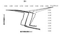
図6は、フェルールの前方端部が管の外周に向けて食い込み駆動されたときの管に対するフェルールの前方端部の相対的な位置に変化を測定したグラフである。図6において、実線で示されている複数のグラフは、フェルール13の前方端部13aが管95の外周に向けて食い込み駆動されたときの前方端部13aの位置の変化をパラメータを変更して複数測定したものである。図6において破線で示されているのは、図1A〜1Cに示したダブルフェルールタイプ継手90におけるフロントフェルール93の前方端部の位置の変化を示す比較例である。 FIG. 6 is a graph obtained by measuring a change in the relative position of the front end portion of the ferrule with respect to the tube when the front end portion of the ferrule is driven into the outer periphery of the tube. In FIG. 6, a plurality of graphs indicated by solid lines change the parameter of the change in the position of the
図6において、横軸が軸方向の相対位置を示し、縦軸が深さ方向の相対変位を示している。横軸および縦軸においてフィンガータイトの状態における相対位置を原点としている。軸方向においては、前方に進むほど負の値が大きくなる。縦軸においては、食い込みが進むほど負の値が大きくなる。 In FIG. 6, the horizontal axis indicates the relative position in the axial direction, and the vertical axis indicates the relative displacement in the depth direction. The relative position in the finger tight state is the origin on the horizontal and vertical axes. In the axial direction, the negative value increases as it moves forward. On the vertical axis, the negative value increases as the bite progresses.
図6を見ると分かるように、フィンガータイトの状態から所定のトルクでネジ結合の締め込みを進めると、最初の段階は、フェルール13の前方端部13aは管95に対して主に軸方向に進行する。しかし、ある所まで来ると、フェルール13の前方端部13aの内周が管95の外周に食いつき、立ち上がり部13cが立ち上がって起こるテコの原理により、前方端部13aが主に食い込み方向に進む段階に移行する。この移行点が図中のグリップポイントである。前方端部13aが主に食い込み方向に進む段階では、軸方向で見ると、前方端部13aは逆に後退している。立ち上がり部13cの立ち上がりが終了すると、前方端部13aは再び主に前方に進行する段階に移行する。このように、立ち上がり部13cが立ち上がるとき、前方端部13aの外周を支点とし、前方端部13aの内周を作用点としてテコの原理が働き、ネジ結合が締め込まれる間の少なくとも一部の段階において、前方端部13aの内周が、ナット12がフェルール13を軸方向に押す力とは軸方向の逆向きに戻りながら、管95の外周に向けて食い込む現象が起こる。 As can be seen from FIG. 6, when the screw connection is tightened with a predetermined torque from the finger tight state, the first stage is that the
このようにフェルール13の前方端部13aが食い込み駆動されることにより、強い力でフェルール13が管95に食い込み、シール性が発揮される。また、フェルール13の前方端部13aが一旦逆方向に戻りながら食い込み駆動されることにより、フェルール13と管95の間が良好にシールされ、高いシール性が発揮される。図6から分かるように、実線で示されたシングルフェルールタイプ継手(本実施形態)が、破線で示されたダブルフェルールタイプ継手とを比べて同程度の深さまでフェルール13の前方端部13aが管95に食い込んでいる。 As described above, the
なお、本実施形態においては、図2に示したように、継手本体11とナット12とのネジ結合がフィンガータイトの状態で、フェルール13の立ち上がり部13cの外周面は、中心軸を通る断面において、継手本体11のテーパ内周面11aと、所定の角度βをなしている。これにより、本実施形態では、立ち上がり部13cを適切な角度βだけ立ち上げることにより、適切な食い込み量の駆動が得られ、フェルール13の前方端部13aと管95との間に良好なシールを得ることができるものとなっている。 In the present embodiment, as shown in FIG. 2, the outer peripheral surface of the rising
また、本実施形態では、図2に示したように、ナット12の押圧部12aには、フェルール13の後方端部13bに当接するテーパ形状の内周面であるテーパ内周面がある。そして、フェルール13は、被押圧部13dの外周面が、中心軸を通る断面において、ナット12のテーパ内周面と所定の角度αをなしている。本実施形態では、被押圧部13dが押圧部12aに押されたとき、中間部13eが外側に広がるのに伴って、被押圧部13dが押圧部12aのテーパ内周面に沿うように立ち上がる。そのときに、フェルール13の後方端部13bは、管95を締め込むように駆動される。そして、本実施形態では、被押圧部13dを適切な角度βだけ立ち上げることにより、適切な締め込み量の駆動が得られ、フェルール13の後方端部13bで管95を良好に保持することができる。 In the present embodiment, as shown in FIG. 2, the
また、本実施形態では、継手本体11の内周面と、ナット12の内周面と、管95の外周面で構成される収納空間の天井面は、フェルール13の立ち上がり部13cが角度βだけ立ち上がった状態で、外径が増大した中間部13eと当接するものであってもよい。これは、フィンガータイトの状態においてフェルール13の中間部13eにある頂部と収納空間の天井面との間隔が所定距離となるように予め設計しておくことで実現することができる。これによれば、立ち上がり部13cが適切な角度βだけ立ち上がり、フェルール13と管95との良好ナシールが得られる状態となると、フェルール13の頂部が収納空間の天井面に当接し、フェルール13が補強されるので、良好なシール性を維持することができる。なお、収納空間の天井面は、継手本体11とナット12のいずれによって構成されていても良い。また、本発明においては、フェルール13の頂部が収納空間の天井面に当接することは必須ではなく、フェルール13の頂部が収納空間の天井面い当接しなくても良い。 Further, in the present embodiment, the rising
また、本実施形態のフェルール13において、前方端部13a、後方端部13b、立ち上がり部13c、被押圧部13d、中間部13eの厚さは特に限定されることは無い。また、立ち上がり部13c、中間部13e、被押圧部13dの長さも特に限定されることは無い。 Moreover, in the
ただし、フェルール13の前方端部13aの厚さが立ち上がり部13cの長さよりも小さいことが好ましい。フェルール13における立ち上がり部13cの長さが前方端部13aの厚さよりも大きければ、立ち上がり部13cが立ち上がることで、その前方端部13aでは、テーパ内周面11aに外周が当接することによって進行が制限され、管95に当接する内周部が管95に食い込むように駆動されるとき、前方端部13aの外周を支点とし、内周を作用点として、テコの原理により、内周が管95に向けて強い力で食い込み駆動されるからである。 However, the thickness of the
また、これとは逆に、フェルール13の前方端部13aの厚さが立ち上がり部13cの長さよりも大きくても良い。その場合、中間部13eの外径を僅かに増大させるだけで、それよりも大きい食い込み量の食い込む駆動をフェルール13の前方端部13aに生じさせることができる。 On the other hand, the thickness of the
また、本実施形態においては、図2、3に示したように、フェルール13の前方端部13aの外周がR面取りされていても良い。前方端部13aの外周がR面取りされているので、立ち上がり部13cが立ち上がるとき、継手本体11に押しつけられた前方端部13aの外周が継手本体11のテーパ内周面11a上を滑り、前方端部13aの内周の管95の上でずれにくく、良好に食い込み駆動することが可能である。 In the present embodiment, as shown in FIGS. 2 and 3, the outer periphery of the
以下、本実施形態による継手10のフェルール13の製造方法の例について説明する。 Hereinafter, the example of the manufacturing method of the
図7は、フェルールを製造する各種加工法について説明するための図である。図7には切削加工を含んだ加工法1〜4が例示されている。 FIG. 7 is a diagram for explaining various processing methods for manufacturing a ferrule. FIG. 7 illustrates processing methods 1 to 4 including cutting.
加工法1は切削加工のみでフェルール13を製作するものである。所定の材料のワークから切削加工によって所望の形状および寸法のフェルール13を製作する。図中右側の前方端部13aを含む立ち上がり部13cの傾斜と、図中左側の後方端部13bを含む被押圧部13dの傾斜の両方を切削加工で形成するので、中間部13e内周面の切削がやや難易度の高いものとなる。 Processing method 1 is to manufacture the
加工法2は、切削加工とプレス加工でフェルール13を製作するものである。 Processing method 2 is to manufacture the
まず最初に切削加工を行い、中間部材22を製作する。前方(図中の右側)の立ち上がり部13cの傾斜は切削加工によって形成する。後方端部13bにおける被押圧部13dの傾斜は切削加工では形成せず、中間部13eから後方端部13bまでの内径および外径を一定としている。 First, cutting is performed to produce the
次にプレス加工を行う。所定形状の金型を用いたプレス加工で後方端部13b近傍をすぼめることにより、被押圧部13dの傾斜を形成する。 Next, press working is performed. By tilting the vicinity of the
この加工法2は、切削加工の段階で製作する中間部材22は後方端部13bが中間部13eと同じ内径なので、加工法1に比べて切削加工の難易度は低い。 In this processing method 2, the
加工法3も切削加工とプレス加工でフェルール13を製作するものである。 The processing method 3 is also for manufacturing the
まず最初に切削加工を行い、中間部材23を製作する。後方の被押圧部13dの傾斜は切削加工によって形成する。前方端部13aにおける立ち上がり部13cの傾斜は切削加工では形成せず、中間部13eから前方端部13aまでの内径を一定としている。また、中間部13eから前方端部13aまでの外径も概ね一定であるが、前方端部13aの外周にR面取りを施している。 First, cutting is performed to produce the
次にプレス加工を行う。所定形状の金型を用いたプレス加工で前方端部13a近傍をすぼめることにより、立ち上がり部13cの傾斜を形成する。 Next, press working is performed. By tilting the vicinity of the
この加工法3は、切削加工の段階で製作する中間部材23は前方端部13aが中間部13eと同じ内径なので、加工法1に比べて切削加工の難易度は低い。 In this processing method 3, the
加工法4も切削加工とプレス加工でフェルール13を製作するものである。 In the processing method 4, the
まず最初に切削加工を行い、中間部材24を製作する。切削加工では、被押圧部13dの傾斜および立ち上がり部13cの傾斜は形成しない。前方端部13aから中間部13eを経て後方端部13bまで内径を一定としている。また、前方端部13aから後方端部13bまでの外径も概ね一定であるが、前方端部13aの外周にR面取りを施している。 First, cutting is performed to manufacture the
次にプレス加工を行う。所定形状の金型を用いたプレス加工で前方端部13a近傍をすぼめ、また後方端部13b近傍をすぼめることにより、立ち上がり部13cの傾斜および被押圧部13dの傾斜を形成する。 Next, press working is performed. The vicinity of the
この加工法4は、切削加工の段階で製作される中間部材24は前方端部13aから後方端部13bまで同じ内径なので、加工法1に比べて切削加工の難易度は低い。また、この例では、中間部材24は前方端部13aから後方端部13bまで内径および外径が均一なので、市販のパイプ材(長管部材)を切断して切削加工に供することで切削加工の工程を短縮することができる。 In this processing method 4, since the
図8は、フェルールを製造する他の加工法について説明するための図である。図8にはプレス加工による加工法が例示されている。 FIG. 8 is a diagram for explaining another processing method for manufacturing a ferrule. FIG. 8 illustrates a processing method by press processing.
図8Aには、プレス加工に供するワーク31が示されている。このワーク31は一例として市販のパイプ材を所定の長さに切断したものである。 FIG. 8A shows a
図8Bでは、金型32〜34からなる金型システムにワーク31をセットした状態が示されている。金型33はワーク31が挿入される挿入口から内部方向(図中右方向)に向けて内周面がテーパ形状にすぼまっている部分がある。また、金型32もワーク31が挿入される挿入口から内部方向(図中左方向)に向けて内数面がテーパ形状にすぼまっている部分がある。ワーク31の貫通孔に挿入する金型34は、同一外径の円柱部分の前方(図中右側)に徐々に外径が減少する先細りの部分がある。 FIG. 8B shows a state in which the
図8Cに示すように、ワーク31の内周に金型34を挿入しつつ、金型33と金型32で前後から挟むようにプレス加工を行い、中間部材35を製作する。金型33の内周面のテーパ形状の部分と、金型34の先細りの部分とによって、フェルール13の立ち上がり部13cが形成される。また、金型32の内周面のテーパ形状の部分と、金型34の同一外径の円柱部分とによって、フェルール13の被押圧部13dの原型部分が形成される。ただし、この段階では、後方端部13bの原型部分は最終的な後方端部13bの内径よりも大きな内径となっている。 As shown in FIG. 8C, the
続いて、図8Dに示すように、図8Cにおける金型32、34を金型36、37に交換した金型システムによってプレス加工を行う。中間部材35の貫通孔に挿入される金型37は、その挿入される部分が最終的な後方端部13bの内径と一致する外径の円柱となっている。また、金型36における中間部材35が挿入される挿入口は、最終的なフェルール13の中間部13eの外径と一致し、その内部方向に向けて内周面がテーパ形状にすぼまっている部分がある。 Subsequently, as shown in FIG. 8D, press working is performed by a mold system in which the
金型37の円柱部分をフェルール13の後方端部13bとなる開口部から挿入すると共に、金型36の内周面がテーパ形状にすぼまっている部分によって、フェルール13の外周面の形状を規制することにより、フェルール13の被押圧部13dが形成される。 The cylindrical portion of the
図8A〜Dの加工法によれば、最初の工程にて、パイプ(管)材料を切断することにより、所定の長さのワーク(短管部材)31を製作し、その後の工程で、ワーク31を加工することによりフェルール13を製作する。そのため、市販されているようなパイプ材量を用いたプレス加工だけでフェルール13を低コストで製造することができる。 8A to 8D, in the first step, a pipe (tube) material is cut to produce a workpiece (short pipe member) 31 having a predetermined length. The
また、この加工法では、図8Cの工程において、フェルール13のシール機構を構成する前方端部13aを2つの金型33、34で形状を規制するようにして形成し、図8Dの工程において、保持機構を構成する後方端部13bの外周面および内周面の形状を2つの金型36、37で規制するようにして開口部をすぼめるので、保持機構に比べてシール機構をより高い精度で形成することができる。 Further, in this processing method, in the step of FIG. 8C, the
また、本実施形態のフェルール13をバルジ成形を用いて製作することも可能である。
例えば、図7Dのプレス加工の代わりにゴムバルジ成形を用いても良い。ゴムに圧力を加えて変形させ、短管部材31の内部に挿入することにより、フェルール13の両端部よりも内径の大きな部分を形成することができる。It is also possible to manufacture the
For example, rubber bulge molding may be used instead of the press work of FIG. 7D. By applying pressure to the rubber to deform it and inserting it into the
本実施形態において継手10および管95の材質は特に限定されない。一例として、継手10を構成する継手本体11、ナット12、およびフェルール13と管95にSUS316ステンレス鋼を用いても良い。また、フェルール13を管95よりもやや強度の高いものとしても良い。例えば、管95として市販されているSUS316を用い、フェルール13として、SUS316に強制引き抜き加工を行って強度を挙げた材量を用いることにしても良い。これにより、フェルール13を管95に向けて良好に食い込ませることができる。 In the present embodiment, the materials of the joint 10 and the
上述した本発明の実施形態は、本発明の説明のための例示であり、本発明の範囲をそれらの実施形態にのみ限定する趣旨ではない。当業者は、本発明の要旨を逸脱することなしに、他の様々な態様で本発明を実施することができる。 The above-described embodiments of the present invention are examples for explaining the present invention, and are not intended to limit the scope of the present invention only to those embodiments. Those skilled in the art can implement the present invention in various other modes without departing from the gist of the present invention.
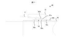
図9は、本実施形態による継手の変形例について説明するための図である。 FIG. 9 is a view for explaining a modification of the joint according to the present embodiment.
図9を参照すると、変形例による継手40は、継手本体41、ナット42、およびフェルール13を有している。 Referring to FIG. 9, the joint 40 according to the modification includes a
継手本体41、ナット42は、図2における継手本体11、ナット12にそれぞれ対応する部品であり、以下に説明する部分以外は基本的に継手本体11、ナット12と共通する。 The joint
継手本体41とナット42とは、互いのネジ結合をフィンガータイトの状態から所定の締め込み量だけ締め込むと、互いに当接して進行を制限する当接部41aと当接部42aをそれぞれ有している。ここでいう所定の締め込み量は、フェルール13が良好に管95に食い込み、良好なシール機構と保持機構が実現されるだけの締め込み量である。 The
本変形例によれば、ネジ結合を所定の締め込み量だけ締め込むと継手本体41とナット42とが当接してそれ以上締め込めなくなるので、目印等で締め込み量を確認しながら締め込みを行わなくても、必要以上に締め込んでしまうのを抑制することができる。 According to this modification, when the screw connection is tightened by a predetermined tightening amount, the
なお、継手40は一旦締め込みを行うと管95が変形したり等があり、継手40を再利用するときには初回使用時よりも多い締め込み量が必要となる。本変形例では、継手40を再利用するとき、収納空間において、フェルール13の被押圧部13dと、ナット42の押圧部42bとの間に所定の厚さのスペーサ43を挟むことで所望の締め込み量の増し締めを可能にしている。スペーサ43の厚さは、所望の増し締めが可能になるだけの厚さである。これにより、継手40の再使用時にスペーサ43を使用することにより、容易に所定量の増し締めが可能となっている。 It should be noted that once the joint 40 is tightened, the
また、ここでは、所定の厚さの1個のスペーサ43を使用する例を示したが、本発明がこれに限定されることは無い。複数のスペーサ43を使用したり、厚さの異なるスペーサ43を使用したりすることもできる。例えば、2回目の再使用(3回目の使用)時以降には、2個以上のスペーサ43をフェルール13の被押圧部13dとナット42の押圧部42bとの間に挟むことで更なる増し締めを可能にしても良い。あるいは2回目の再使用(3回目の使用)時以降には、1回目の再使用(2回目の使用)時に用いたスペーサ43よりも厚さが大きいスペーサ43をフェルール13の被押圧部13dとナット42の押圧部42bとの間に挟むことで更なる増し締めを可能にしても良い。 Although an example in which one
また、本変形例では、再使用時に追加するスペーサ43を利用する例であるが、本発明がこれに限定されることは無い。他の例として、初回使用時に使用し、再使用時には使用しないスペーサを用いても良い。例えば、図9における継手本体41の当接部41aと、ナット42の当接部42aとの間に、所定の厚さのスペーサを配置することにすればよい。これによれば、継手40の再使用時にスペーサを除去することにより、容易に所定量の増し締めが可能となる。 Moreover, in this modification, although it is an example using the
図10は、他の変形例による継手について説明するための図である。 FIG. 10 is a diagram for explaining a joint according to another modification.
図10を参照すると、本変形例の継手50は、継手本体11、ナット51、およびフェルール13を有している。 Referring to FIG. 10, the joint 50 of this modification includes a
ナット51は、図2におけるナット12に対応する部品であり、以下に説明する部分以外は基本的にナット12と共通する。 The
ナット12は、フェルール13を押圧する押圧部52が凹部53と凸部54を有している。中心軸から凹部53の外側に凸部54があり、凹部53よりも凸部54の方が軸方向の前方に位置している。 In the
図10Aに示すように、フィンガータイトの状態では凹部53がフェルール13の後方端部13bに当接している。この状態から継手本体11とナット51のネジ結合を締め込むと、凹部53がフェルール13の後方端部13bを押圧し、フェルール13の中間部13eの全体の内径および外径が増大し始める。しかし、中間部13eの後方側が上方にある凸部54に当接し、それ以降は中間部13eの後方側の外径の増大が外側にある凸部54によって規制される。 As shown in FIG. 10A, the
そのため、中間部13eの全体の外径を増大することができず、押圧部52から受ける力F1から派生した径を増大する力F2が中間部13eの凸部54よりも前方に集中する。その結果、図10Bに示すように、中間部13eの凸部54よりも前方の部分の外径が大きく増大するので、フェルール13の前方端部13aに効率良く回転運動が起こり、前方端部13aの内周が管95に向けて食い込み駆動される。 Therefore, the overall outer diameter of the
図11は、更に他の変形例による継手について説明するための図である。 FIG. 11 is a view for explaining a joint according to still another modification.
図11を参照すると、継手60は、継手本体11、ナット61、およびフェルール62を有している。図2、3等の実施形態のフェルール13は、被押圧部13dが後方端部13bを含むものであったが、本発明がそれに限定されることは無い。 Referring to FIG. 11, the joint 60 includes a
本変形例では、図11に示すように、フェルール62の被押圧部62aは後方端部62bを含まず、後方端部62bよりも前方に位置している。被押圧部62aと後方端部62bの間は外径および内径が後方端部62bと同一な管状部62cとなっている。 In this modified example, as shown in FIG. 11, the pressed
また、本変形例のナット61は、押圧部61aの最小内径が、管95の外径よりも、フェルール62の管状部62cが通る分だけ大きくなっている。 Further, in the
本実施例においても、継手本体11とナット61のネジ結合を締め込むと、後方端部62bがナット61の後方に突出したフェルール62の被押圧部62aをナット61の押圧部61aが押圧する。被押圧部62aを押圧されたフェルール62の中間部62dの内径および外径が増大し、前方端部62eにて回転運動が起こり、前方端部62eの内周が管95に向けて食い込み駆動される。 Also in this embodiment, when the screw connection between the
図12は、更に他の変形例による継手について説明するための図である。 FIG. 12 is a view for explaining a joint according to still another modification.
図12を参照すると、本変形例の継手70は、継手本体11、ナット12、およびフェルール71を有している。フェルール71は、図2におけるフェルール13に対応する部品であり、以下に説明する部分以外は基本的にフェルール13と共通する。 Referring to FIG. 12, the joint 70 of this modification includes a
本変形例のフェルール71は中間部71aに軸方向の特定位置に径方向に非均一な形状の部分(非均一形状部71b)がある。図12の例では、中間部71aに含まれる非均一形状部71bが中間部71aの他の部分よりも厚さが薄くなっている。 The
非均一形状部71bは、フェルール71の軸方向の特定位置において内周面に一周連続して掘られた溝によって実現されている。本変形例のフェルール71は非均一形状部71bがあるために、図2、3に示したフェルール13と比べて、中間部aの内径および外径を増大させるように変形しやすくなっている。そのため、前方端部71cに回転運動を生じさせるための締め付けトルクを小さく抑えることができる。 The non-uniformly shaped
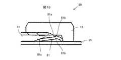
図13は、更に他の変形例による継手について説明するための図である。 FIG. 13 is a view for explaining a joint according to still another modification.
図13を参照すると、本変形例の継手80は、継手本体11、ナット12、およびフェルール81を有している。フェルール81は、図2におけるフェルール13に対応する部品であり、以下に説明する部分以外は基本的にフェルール13と共通する。 Referring to FIG. 13, the joint 80 according to this modification includes a
本変形例のフェルール81も中間部81aに軸方向の特定位置に非均一形状部81bがある。図13の例では、非均一形状部81bとして、内周面の内径が他の部分と異なる部分と、外周面の外径が他の部分と異なる部分とがある。具体的に、中心軸を通る断面で見たとき、内周面には窪んだ部分があり、外周面には突出した部分がある。これらはフェルール81の内周面から軸方向の特定位置に対するパンチ加工によって形成された非均一形状部81bである。 The
本変形例のフェルール81は非均一形状部81bがあるために、図2、3に示したフェルール13と比べて、中間部aの内径および外径を増大させるように変形しやすくなっている。そのため、前方端部81cに回転運動を生じさせるための締め付けトルクを小さく抑えることができる。 Since the
なお、本変形例では、フェルール81の内周面からパンチを打った例を示したが、本発明がこれに限定されることは無く、外周面からパンチを打って非均一形状部を形成しても良い。 In this modification, an example in which a punch is punched from the inner peripheral surface of the
また、ここでは非均一形状部81bをパンチ加工によって形成する例を示したが、本発明がこれに現地されることは無い。他の例として、切削加工によって非均一形状部81bを形成しても良い。 Moreover, although the example which forms the non-uniform |
また、本変形例のフェルール81を一周している非均一形状部81bを一回のパンチ加工で形成する必要はなく、複数回に分けてパンチ加工を行っても良い。 Further, it is not necessary to form the non-uniformly shaped
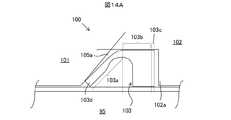
図14A、Bは、更に他の変形例による継手について説明するための図である。 14A and 14B are views for explaining a joint according to still another modification.
図14Aを参照すると、継手100は、継手本体101、ナット102、およびフェルール103で構成されている。フェルール103には、立ち上がり部103a、中間部103b、および被押圧部103cを有している。なお、図中では中間部103bと被押圧部103cの境界が破線によって示されているが、この破線が中間部103bと被押圧部103cとを厳密に分ける位置を示すものではない。この破線は、明細書の説明において中間部103bと被押圧部103bのそれぞれの機能を説明しやすいようにするために便宜的に引いた線である。 Referring to FIG. 14A, the joint 100 includes a
本変形例では、立ち上がり部103の左方に第1の許容空間はあるが、中間部103bの外側に第2の許容空間は無い。また、立ち上がり部103aにおける中間部103bの近傍に内周面が窪み中間部103bの他の部分よりも厚さが薄くなっている部分(非均一形状部分)がある。 In the present modification, there is a first allowable space on the left side of the rising
フィンガータイトの状態から、継手本体101とナット102のネジ結合を締め込むと、図14Bのように、ナット102の押圧部102aがフェルール103の被押圧部103cを軸方向に押す。フェルール103の立ち上がり部103aは軸方向に押されて主に厚さの薄い部分が変形して立ち上がる。そのとき中間部103bの外径はほとんど増大しない。立ち上がり部103aが立ち上がることで、フェルール103の前方端部103dで回転運動が起こり、前方端部103dの外周を支点とし内周を作用点としてテコの原理で内周が管95の外周面に向けて食い込み駆動される。 When the screw connection between the
このように、フィンガータイトの状態で、フェルール103の中間部103bの外側に第2の許容空間が無くても、立ち上がり部103aの外側に立ち上がり部103aが立ち上がるだけの第1の許容空間105aがあれば、前方端部103dに回転運動を起こし、テコの原理で内周を管95の外周面に向けて食い込み駆動することができる。 In this manner, in the finger tight state, even if there is no second allowable space outside the
なお、本変形例では、フェルール103の被押圧部103cとナット102の押圧部102aとにおける互いに当接する面が共に中心軸に対して垂直な平坦な面である例を示したが、本発明がこの例に限定されることは無い。他の例として、それらの面が中心軸に対して垂直で無くても良い。また、それらの面が平面で無くても良い。例えば、フェルール103の被押圧部103cに凹部があり、その凹部に対応するナット102の押圧部102aの位置に凸部があっても良い。また、フェルール103の被押圧部103cが平坦な面であり、ナット102の押圧部102aに凸部があっても良い。 In this modification, an example is shown in which the surfaces of the pressed
また、本変形例では、フェルール103の立ち上がり部103aの厚さが薄い部分を設けることにより、前方端部103dに回転運動が起こり易くした例を示したが、本発明がこの例に限定されることは無い。第1の許容空間があるので、フェルール103の厚さがが均一であっても、ナット102によって軸方向に押されれば、立ち上がり部103が立ち上がり、前方端部103dに回転運動が起こる。 Further, in this modification, the example in which the rising
また、本変形例では、フェルール103の中間部103bの厚さを立ち上がり部103aと比べて厚くすることにより、ナット102によって軸方向に押されたときに中間部103bの外径が増大するのを防止している。しかしながら、本発明がこの例に限定されることは無い。他の例として、ナット102の内周によって構成される天井がフェルール103の中間部103bの外径が増大するのを防止することにしても良い。その場合、天井が円筒内周面を構成するものであっても良く、また、ナット102の内周におけるフェルール103の中間部103bに対応する位置に環状の凸部を1本あるいは複数本配設し、それによって中間部103bの外径が増大するのを防止することにしても良い。 Further, in this modification, by increasing the thickness of the
また、図2、3の実施形態において、押圧部12aは、中心軸を通る断面において、管95の外周面と鋭角をなす例を示したが、本発明がこれに限定されることは無い。他の例として、押圧部12aが管95の外周面に対して垂直であっても良い。ナット12の押圧部12aが垂直であれば、フェルール13の被押圧部13dに軸方向に効率良く力が加わり、またそれに派生するフェルール13の中間部13eの内径および外径を増大させる力も発生しやすくなる。その結果、フェルール13の前方端部13aにおける回転運動が起こりやすくなる。 In the embodiment of FIGS. 2 and 3, the
また、図2、3の実施形態においては、ナット12がフェルール13の被押圧部13dを軸方向に押し、継手本体11とフェルール13の前方端部13aとが当接し、フェルール13の立ち上がり部13cが継手本体11のテーパ内周面11aに向けて立ち上がる例を示したが、本発明がこの例に限定されることは無い。他の例として、フェルール13の立ち上がり部13cと被押圧部13dが逆に配設されていても良い。その場合、ナット12には、フェルール13の前方端部13と当接する、図2では継手本体11にあるテーパ内周面11aと同様のテーパ内周面がある。ナット12がそのテーパ内周面によって立ち上がり部13cを軸方向に押すと、フェルール13の被押圧部13dに当接する継手本体11が相対的に被押圧部13dを押し返す。それによって、フェルール13が変形し、ナット12に当接している前方端部に回転運動が起こり、前方端部の外周が支点となり、内周が作用点となってテコの原理によって内周が管95の外周に向けて食い込み駆動される。 2 and 3, the
10…継手、11…継手本体、11a…テーパ内周面、12…ナット、12a…押圧部、13…フェルール、13a´…先端、13a…前方端部、13b…後方端部、13c…立ち上がり部、13c´…部材、13d…被押圧部、13d´…部材、13e…接続点、13e´…中間部、13f…弾性体、13g…支点、13h…作用点、13h´…先端、15…許容空間、15a…第1の許容空間、15b…第2の許容空間、2…加工法、22…中間部材、23…中間部材、24…中間部材、31…ワーク、32…金型、33…金型、34…金型、35…中間部材、36…金型、37…金型、40…継手、41…継手本体、41a…当接部、42…ナット、42a…当接部、42b…押圧部、43…スペーサ、50…継手、51…ナット、52…押圧部、53…凹部、54…凸部、60…継手、61…ナット、61a…押圧部、62…フェルール、62a…被押圧部、62b…後方端部、62c…管状部、62d…中間部、62e…前方端部、70…継手、71…フェルール、71a…中間部、71b…非均一形状部、71c…前方端部、80…継手、81…フェルール、81a…中間部、81b…非均一形状部、81c…前方端部、90…ダブルフェルールタイプ継手、91…継手本体、92…ナット、93…フロントフェルール、94…バックフェルール、95…管、100…継手、101…継手本体、102…ナット、102a…押圧部、103…フェルール、103a…立ち上がり部、103b…中間部、103c…被押圧部、103d…前方端部、105a…第1の許容空間
DESCRIPTION OF
Claims (14)
Translated fromJapanese前記管を受け入れる貫通孔を有する第1部材と、
前記管を受け入れる貫通孔を有し、該貫通孔の中心軸を前記第1部材の貫通孔の中心軸と一致させて前記第1部材とネジ結合する第2部材と、
前記管を受け入れる第1端部から第2端部まで通ずる貫通孔を有し、前記第1端部と前記第2端部の間に前記第1端部および前記第2端部よりも内径が大きい部分があり、該貫通孔の中心軸を前記第1部材および前記第2部材の中心軸と一致させて、前記第1部材の内周面と前記第2部材の内周面と前記管の外周面とで形成される収納空間に配置されるフェルールと、を有し、
前記フェルールには、前記第1端部を含む立ち上がり部と、前記立ち上がり部よりも前記第2端部側にある被押圧部と、前記第1端部および前記第2端部よりも内径が大きい部分を含み前記立ち上がり部と前記被押圧部を接続する中間部とがあり、
前記第1部材には、前記フェルールの前記第1端部に当接するテーパ形状の内周面である第1テーパ内周面があり、
前記第2部材には、前記フェルールの前記被押圧部の少なくとも一部を押圧する押圧部があり、
前記収納空間には、前記フェルールを収納して前記立ち上がり部を前記管の外周面とのなす角を増大させるように立ち上げることができる第1の許容空間があり、
前記第1部材と前記第2部材のネジ結合を締めこむと前記フェルールの前記立ち上がり部が立ち上がり、前記第1端部の外周を支点として該第1端部の内周が作用点となって回転し、前記管の外周に向けて食い込み駆動される、
継手。A joint connecting to a pipe,
A first member having a through hole for receiving the tube;
A second member that has a through-hole that receives the tube, and that is screw-coupled to the first member so that the central axis of the through-hole coincides with the central axis of the through-hole of the first member;
It has a through-hole which leads from the 1st end which receives the pipe to the 2nd end, and an inner diameter is between the 1st end and the 2nd end rather than the 1st end and the 2nd end. There is a large portion, and the central axis of the through hole is aligned with the central axis of the first member and the second member, and the inner peripheral surface of the first member, the inner peripheral surface of the second member, and the pipe And a ferrule disposed in a storage space formed by the outer peripheral surface,
The ferrule has a rising portion including the first end portion, a pressed portion closer to the second end portion than the rising portion, and a larger inner diameter than the first end portion and the second end portion. There is an intermediate part that includes the part and connects the rising part and the pressed part,
The first member has a first tapered inner peripheral surface that is a tapered inner peripheral surface that contacts the first end of the ferrule,
The second member has a pressing portion that presses at least a part of the pressed portion of the ferrule,
Wherein the receiving space isRi first allowable space there which can launch the rising portion and accommodating the ferrule so as to increase the angle between the outer peripheral surface of thetube,
When the screw connection between the first member and the second member is tightened, the rising portion of the ferrule rises and rotates with the outer periphery of the first end as a fulcrum and the inner periphery of the first end as a working point and, Rudriven bite toward the outer periphery of the tube,
Fittings.
前記第1部材または前記第2部材による前記収納空間の天井面は、前記フェルールの前記立ち上がり部が前記第1の角度だけ立ち上がった状態で、外径が増大した前記中間部と当接する、請求項1〜4のいずれか一項に記載の継手。When the screw connection between the first member and the second member is finger tight, the outer peripheral surface of the rising portion of the ferrule has a first predetermined inner surface with the first tapered inner peripheral surface in a cross section passing through the central axis.to name the angleof,
The ceiling surface of the storage space formed by the first member or the second member is in contact with the intermediate portion having an increased outer diameter in a state where the rising portion of the ferrule has risen by the first angle. The joint as described in any one of 1-4.
前記第1部材と前記第2部材のネジ結合がフィンガータイトの状態で、前記フェルールの前記被押圧部の外周面が、前記中心軸を通る断面において、前記第2テーパ内周面と所定の第2の角度をなす、
請求項1〜7のいずれか一項に記載の継手。The pressing portion of the second member has a second tapered inner peripheral surface that is a tapered inner peripheral surface that contacts the second end of the ferrule,
When the screw connection between the first member and the second member is finger tight, the outer peripheral surface of the pressed portion of the ferrule has a predetermined first and second taper inner surface in a cross section passing through the central axis. Make an angle of 2,
The joint according to any one of claims 1 to7 .
長管部材を切断することにより、前記第1端部および前記第2端部となる両端間において外径および内径が均一で所定の長さの短管部材を製作する第1ステップと、
前記短管部材を加工することにより、前記管を収容することが可能な内径を共に有する前記第1端部と前記第2端部の間に、前記立ち上がり部と前記中間部と前記被押圧部と形成する第2ステップと、を有するフェルール製造方法。A first member having a through-hole for receiving a tube; and a through-hole for receiving the tube, wherein the central axis of the through-hole is aligned with the central axis of the through-hole of the first member and screwed to the first member A second member that has a through hole that extends from a first end that receives the tube to a second end, and the first end and the second end between the first end and the second end. There is a portion having an inner diameter larger than that of the end portion, and the inner surface of the first member and the inner surface of the second member are aligned with the central axes of the first member and the second member. A ferrule disposed in a storage space formed by a peripheral surface and an outer peripheral surface of the tube, wherein the ferrule includes a rising portion including the first end portion and the second portion more than the rising portion. A pressed portion on the end side, and a portion having a larger inner diameter than the first end portion and the second end portion The first member has a first taper inner peripheral surface that is a tapered inner peripheral surface that contacts the first end of the ferrule, and has an intermediate portion that connects the rising portion and the pressed portion. The second member has a pressing portion that presses at least a part of the pressed portion of the ferrule, and stands so as to accommodate the ferrule and increase an angle between the rising portion and the outer peripheral surface of the tube. There is a first permissible space that can be raised in the storage space, and when the screw connection of the first member and the second member is tightened, the rising portion of the ferrule rises, and the outer periphery of the first end portion is a fulcrum The ferrule manufacturing method for manufacturing the ferrule usedfor a joint ,whereinthe inner periphery of the first end rotates as an action point and is driven into the outer periphery of the pipe ,
A first step of producing a short tube member having a predetermined length with an outer diameter and an inner diameter uniform between both endsto be the first end and the second end by cutting a long tube member;
By processing the short pipe member, betweenthesecond end and the first end portion having both an internal diameter which can accommodate thetube, the pressed portion and the rising portion and the intermediate portion And a second step offorming a ferrule.
前記フェルールにおける前記管とのシール機構を構成する第1端部を、金型によって、外周面および内周面の形状を規制するようにして形成する第3ステップと、
前記フェルールにおける前記管の保持機構を構成する第2端部を、金型によって、外周面の形状を規制して開口部をすぼめることで形成する第4ステップと、
を有する、請求項13に記載のフェルール製造方法。The second step includes
A third step of forming a first end portion constituting a sealing mechanism with the pipe in the ferrule so as to regulate the shape of the outer peripheral surface and the inner peripheral surface by a mold;
A fourth step of forming a second end portion constituting the holding mechanism of the pipe in the ferrule by restricting the shape of the outer peripheral surface by using a mold and squeezing the opening;
The ferrule manufacturing method of Claim 13 which has these.
Priority Applications (11)
| Application Number | Priority Date | Filing Date | Title |
|---|---|---|---|
| JP2012169271AJP5231671B1 (en) | 2012-07-31 | 2012-07-31 | Fitting and ferrule manufacturing method thereof |
| US14/418,525US9829129B2 (en) | 2012-07-31 | 2013-05-20 | Fitting, ferrule, and ferrule manufacturing method |
| PCT/JP2013/063906WO2014020968A1 (en) | 2012-07-31 | 2013-05-20 | Joint, ferrule, and method for manufacturing ferrule |
| KR1020147027894AKR101561547B1 (en) | 2012-07-31 | 2013-05-20 | Joint, ferrule, and method for manufacturing ferrule |
| EP13826387.6AEP2881640B1 (en) | 2012-07-31 | 2013-05-20 | Fitting, ferrule, and method for manufacturing ferrule |
| CN201611180278.7ACN106764146B (en) | 2012-07-31 | 2013-05-20 | Connector, casing and method of making sleeve tube |
| CN201380017630.3ACN104246340B (en) | 2012-07-31 | 2013-05-20 | Joint, bushing and bushing manufacturing method |
| TW102127049ATWI576527B (en) | 2012-07-31 | 2013-07-29 | Sleeve, manufacturing method thereof and tube connecter |
| TW106101974ATWI636216B (en) | 2012-07-31 | 2013-07-29 | Manufacturing method of sleeve |
| IN1174DEN2015IN2015DN01174A (en) | 2012-07-31 | 2015-02-13 | |
| US15/811,899US11092267B2 (en) | 2012-07-31 | 2017-11-14 | Fitting, ferrule, and ferrule manufacturing method |
Applications Claiming Priority (1)
| Application Number | Priority Date | Filing Date | Title |
|---|---|---|---|
| JP2012169271AJP5231671B1 (en) | 2012-07-31 | 2012-07-31 | Fitting and ferrule manufacturing method thereof |
Related Child Applications (1)
| Application Number | Title | Priority Date | Filing Date |
|---|---|---|---|
| JP2013055301ADivisionJP6007140B2 (en) | 2013-03-18 | 2013-03-18 | Fitting and ferrule manufacturing method thereof |
Publications (2)
| Publication Number | Publication Date |
|---|---|
| JP5231671B1true JP5231671B1 (en) | 2013-07-10 |
| JP2014029165A JP2014029165A (en) | 2014-02-13 |
Family
ID=48913966
Family Applications (1)
| Application Number | Title | Priority Date | Filing Date |
|---|---|---|---|
| JP2012169271AActiveJP5231671B1 (en) | 2012-07-31 | 2012-07-31 | Fitting and ferrule manufacturing method thereof |
Country Status (8)
| Country | Link |
|---|---|
| US (2) | US9829129B2 (en) |
| EP (1) | EP2881640B1 (en) |
| JP (1) | JP5231671B1 (en) |
| KR (1) | KR101561547B1 (en) |
| CN (2) | CN104246340B (en) |
| IN (1) | IN2015DN01174A (en) |
| TW (2) | TWI636216B (en) |
| WO (1) | WO2014020968A1 (en) |
Cited By (2)
| Publication number | Priority date | Publication date | Assignee | Title |
|---|---|---|---|---|
| CN104181342A (en)* | 2014-09-01 | 2014-12-03 | 上海理工大学 | Oscilloscope probe contact fixing part facilitating measurement |
| JP2015152112A (en)* | 2014-02-17 | 2015-08-24 | イハラサイエンス株式会社 | Joint and ferrule |
Families Citing this family (10)
| Publication number | Priority date | Publication date | Assignee | Title |
|---|---|---|---|---|
| US9695963B2 (en) | 2011-05-10 | 2017-07-04 | Patrick L. Rieth | Tube-fitting-assembly ferrule |
| JP2015197200A (en)* | 2014-04-03 | 2015-11-09 | イハラサイエンス株式会社 | Joint |
| JP6387252B2 (en)* | 2014-06-18 | 2018-09-05 | イハラサイエンス株式会社 | Fittings and ferrules |
| WO2017105527A1 (en)* | 2015-12-16 | 2017-06-22 | Rieth Patrick L | Tube-fitting-assembly ferrule |
| CN106694689B (en)* | 2017-02-14 | 2018-12-07 | 珠海格力智能装备技术研究院有限公司 | Pipe processing device |
| WO2018231218A1 (en)* | 2017-06-14 | 2018-12-20 | Cleveland Tool & Machine, Inc. | Apparatus and method for production of duct members |
| CN109470109A (en)* | 2018-10-26 | 2019-03-15 | 东莞市爱德光设计有限公司 | Joint measurement method based on male-female docking application |
| JP2020139541A (en)* | 2019-02-27 | 2020-09-03 | イハラサイエンス株式会社 | Joint structure |
| CN114096777B (en)* | 2019-07-03 | 2024-06-04 | 姜锡在 | Air-tight device for pipeline |
| CN111562471B (en)* | 2020-05-09 | 2022-08-26 | 贵州电网有限责任公司 | SF6 inflation connector universally applicable |
Citations (6)
| Publication number | Priority date | Publication date | Assignee | Title |
|---|---|---|---|---|
| JPS55181082U (en)* | 1979-06-14 | 1980-12-26 | ||
| JPS5815745Y2 (en)* | 1978-09-18 | 1983-03-30 | エス・エム・ジェ−工業株式会社 | pipe fittings |
| JP2005036946A (en)* | 2003-07-18 | 2005-02-10 | Ihara Science Corp | Pipe fitting |
| JP2007170658A (en)* | 2005-11-22 | 2007-07-05 | Kane Kogyo Kk | Pipe fitting |
| JP2007239947A (en)* | 2006-03-10 | 2007-09-20 | Daikin Ind Ltd | Pipe fittings, refrigeration equipment, heat pump water heater, and water supply piping |
| JP2009014115A (en)* | 2007-07-05 | 2009-01-22 | Higashio Mech Co Ltd | Connection structure |
Family Cites Families (54)
| Publication number | Priority date | Publication date | Assignee | Title |
|---|---|---|---|---|
| US1698999A (en) | 1927-01-24 | 1929-01-15 | American Can Co | Necking-in or reforming tubular bodies |
| US1799246A (en)* | 1927-07-26 | 1931-04-07 | Chase Companies Inc | Metallic packing ring for slip-joint pipe connections |
| US1781222A (en)* | 1928-04-09 | 1930-11-11 | Republic Brass Company | Pipe joint or connection |
| GB409692A (en) | 1932-11-02 | 1934-05-02 | Montague William Tutt | Improvements in or relating to joints for metal pipes |
| US2230116A (en)* | 1938-10-31 | 1941-01-28 | Patex Sa | Pipe coupling |
| US2255673A (en)* | 1940-02-05 | 1941-09-09 | Wagner Malleable Products Comp | Nut |
| US2288506A (en)* | 1940-08-30 | 1942-06-30 | Crouse Hinds Co | Watertight threadless connector |
| US2343922A (en)* | 1943-03-16 | 1944-03-14 | Parker Appliance Co | Tube coupling |
| US2738994A (en)* | 1950-06-28 | 1956-03-20 | Kreidel Hans | Cam actuated gland type pipe coupling |
| US3107108A (en)* | 1957-11-26 | 1963-10-15 | Whitney E Greene | Tube coupling |
| GB881304A (en) | 1958-01-31 | 1961-11-01 | Wade Couplings Ltd | Improvements in and relating to high pressure pipe fittings |
| US3007721A (en)* | 1958-09-22 | 1961-11-07 | Battelle Memorial Institute | Flareless tube coupling and ferrule therefor |
| FR1297897A (en) | 1961-05-26 | 1962-07-06 | Cie Parisienne Outil Air Compr | Ring connection |
| FR1408909A (en) | 1964-07-09 | 1965-08-20 | Ermeto Sa | Fitting with rings, in particular for joining plastic pipes or other applications, as well as rings conforming or similar to the previous ones |
| US3248136A (en)* | 1964-07-21 | 1966-04-26 | Chicago Fitting Corp | Fitting assembly for metal tubes |
| US3393931A (en)* | 1966-02-07 | 1968-07-23 | Paul D. Wurzburger | Tube coupling with bias cutting edge |
| US3499671A (en)* | 1968-12-31 | 1970-03-10 | Parker Hannifin Corp | Flareless tube coupling |
| GB1356821A (en)* | 1970-10-22 | 1974-06-19 | Crown Cork & Seal Co | Method of and apparatus for deforming open ends of container bodies |
| US3888521A (en)* | 1973-07-11 | 1975-06-10 | Parker Hannifin Corp | Tube coupling and ferrule therefor |
| JPS513917U (en)* | 1974-06-27 | 1976-01-13 | ||
| JPS513917A (en) | 1974-06-29 | 1976-01-13 | Kubota Ltd | TSUCHOSEYOKAITENRASENTAI |
| US4019762A (en)* | 1974-08-27 | 1977-04-26 | I-T-E Imperial Corporation | Raintight connector for electrical conduit |
| US4159134A (en)* | 1977-09-19 | 1979-06-26 | Gould, Inc. | Electrical conduit connector |
| JPS5921757B2 (en) | 1979-02-07 | 1984-05-22 | メイキ樹脂工業株式会社 | Operating mechanism in industrial automatic machines |
| JPS5619516A (en) | 1979-07-25 | 1981-02-24 | Hitachi Ltd | Magnetic head |
| JPS5815745A (en) | 1981-07-20 | 1983-01-29 | Matsushita Electric Ind Co Ltd | hot gas engine |
| US4508466A (en)* | 1983-02-07 | 1985-04-02 | Dennis Victor S | Lockable telescopic joint |
| JPH0243073A (en) | 1988-08-03 | 1990-02-13 | Nec Corp | Printing information edition system |
| DE4304534A1 (en) | 1993-02-16 | 1994-08-18 | Klaus D Lehmann | Connection system for pipelines |
| JPH10249459A (en)* | 1997-03-11 | 1998-09-22 | Nakagawa Sangyo Kk | Method for reducing tube made of metal |
| US6629708B2 (en) | 1997-04-15 | 2003-10-07 | Swagelok Company | Ferrule with relief to reduce galling |
| JP3894387B2 (en)* | 1997-11-28 | 2007-03-22 | ステンレスパイプ工業株式会社 | Manufacturing method of pipe joint and pipe joint obtained by the method |
| JP2000046262A (en)* | 1998-07-28 | 2000-02-18 | Ihara Science Corp | Pipe coupling and its connecting method |
| JP3671760B2 (en)* | 1999-09-01 | 2005-07-13 | トヨタ自動車株式会社 | Ring member forming method and press machine |
| US7416225B2 (en) | 2001-02-06 | 2008-08-26 | Swagelok Company | Fitting for metal pipe and tubing |
| ES2238557T3 (en) | 2001-02-06 | 2005-09-01 | Swagelok Company | TUBE COUPLING WITH A SEPARABLE TUBE FIXING RING. |
| US20050194785A1 (en)* | 2003-10-03 | 2005-09-08 | Sami Shemtov | Rain tight compression fitting coupling device |
| US20080007050A1 (en) | 2003-11-03 | 2008-01-10 | Williams Peter C | Fitting for metal pipe and tubing |
| CA2469353A1 (en)* | 2004-05-31 | 2005-11-30 | Masco Canada Limited | Pipe coupling |
| KR20080091186A (en) | 2006-01-13 | 2008-10-09 | 스와겔로크 컴패니 | Fitting for tube or pipe |
| CA2668476A1 (en) | 2006-11-02 | 2008-05-15 | Swagelok Company | Pull-up by torque fitting |
| ITVI20060355A1 (en)* | 2006-12-14 | 2008-06-15 | Ciro Mastromatteo | CONNECTION BUSH FOR CONNECTION OF PIPES TO TERMINALS |
| DE102007034032A1 (en)* | 2007-07-20 | 2009-01-22 | Robert Bosch Gmbh | Method and device for producing a high-pressure-tight connection and associated valve cartridge for a solenoid valve |
| CN101821541A (en) | 2007-08-03 | 2010-09-01 | 斯瓦戈洛克公司 | Connect by moment of torsion lasso pipe joint |
| JP4914337B2 (en)* | 2007-12-26 | 2012-04-11 | 株式会社タブチ | Resin pipe fitting |
| KR100943720B1 (en)* | 2008-09-09 | 2010-02-23 | (주)휘일 | A method for manufacture container which loosen fluid-shock or mechanical-shock |
| CN201275579Y (en)* | 2008-10-23 | 2009-07-22 | 应端忠 | Double-ended necking and concentricity processing equipment |
| CN201322153Y (en)* | 2008-11-13 | 2009-10-07 | 阮浩丰 | Cutting sleeve type pipe connector |
| WO2010096675A1 (en)* | 2009-02-20 | 2010-08-26 | Swagelok Company | Conduit fitting with split torque collar |
| DE102009036251A1 (en)* | 2009-08-05 | 2011-02-10 | Andreas Daub Gmbh & Co. Kg | Method for producing a decorative ring |
| CN201500732U (en)* | 2009-09-22 | 2010-06-09 | 上海纳铁福传动轴有限公司 | Transmission shaft tube shrinking mold |
| CN201810901U (en)* | 2010-09-10 | 2011-04-27 | 胡启宇 | Universal joint |
| CN102253140A (en) | 2011-06-22 | 2011-11-23 | 红云红河烟草(集团)有限责任公司 | A method for determining the content of benzene and benzene series in water-based adhesive for tobacco |
| CN102252140B (en)* | 2011-07-21 | 2012-10-10 | 浙江大学 | Seal joint of deep low-temperature nonmetal pipeline |
- 2012
- 2012-07-31JPJP2012169271Apatent/JP5231671B1/enactiveActive
- 2013
- 2013-05-20EPEP13826387.6Apatent/EP2881640B1/enactiveActive
- 2013-05-20CNCN201380017630.3Apatent/CN104246340B/enactiveActive
- 2013-05-20WOPCT/JP2013/063906patent/WO2014020968A1/enactiveApplication Filing
- 2013-05-20KRKR1020147027894Apatent/KR101561547B1/enactiveActive
- 2013-05-20CNCN201611180278.7Apatent/CN106764146B/enactiveActive
- 2013-05-20USUS14/418,525patent/US9829129B2/enactiveActive
- 2013-07-29TWTW106101974Apatent/TWI636216B/enactive
- 2013-07-29TWTW102127049Apatent/TWI576527B/enactive
- 2015
- 2015-02-13ININ1174DEN2015patent/IN2015DN01174A/enunknown
- 2017
- 2017-11-14USUS15/811,899patent/US11092267B2/enactiveActive
Patent Citations (6)
| Publication number | Priority date | Publication date | Assignee | Title |
|---|---|---|---|---|
| JPS5815745Y2 (en)* | 1978-09-18 | 1983-03-30 | エス・エム・ジェ−工業株式会社 | pipe fittings |
| JPS55181082U (en)* | 1979-06-14 | 1980-12-26 | ||
| JP2005036946A (en)* | 2003-07-18 | 2005-02-10 | Ihara Science Corp | Pipe fitting |
| JP2007170658A (en)* | 2005-11-22 | 2007-07-05 | Kane Kogyo Kk | Pipe fitting |
| JP2007239947A (en)* | 2006-03-10 | 2007-09-20 | Daikin Ind Ltd | Pipe fittings, refrigeration equipment, heat pump water heater, and water supply piping |
| JP2009014115A (en)* | 2007-07-05 | 2009-01-22 | Higashio Mech Co Ltd | Connection structure |
Cited By (3)
| Publication number | Priority date | Publication date | Assignee | Title |
|---|---|---|---|---|
| JP2015152112A (en)* | 2014-02-17 | 2015-08-24 | イハラサイエンス株式会社 | Joint and ferrule |
| CN104181342A (en)* | 2014-09-01 | 2014-12-03 | 上海理工大学 | Oscilloscope probe contact fixing part facilitating measurement |
| CN104181342B (en)* | 2014-09-01 | 2017-02-15 | 上海理工大学 | Oscilloscope probe contact fixing part facilitating measurement |
Also Published As
| Publication number | Publication date |
|---|---|
| CN104246340A (en) | 2014-12-24 |
| TW201407073A (en) | 2014-02-16 |
| CN104246340B (en) | 2017-02-22 |
| WO2014020968A1 (en) | 2014-02-06 |
| CN106764146B (en) | 2019-01-11 |
| TW201715167A (en) | 2017-05-01 |
| US20180066775A1 (en) | 2018-03-08 |
| CN106764146A (en) | 2017-05-31 |
| KR20140137413A (en) | 2014-12-02 |
| JP2014029165A (en) | 2014-02-13 |
| KR101561547B1 (en) | 2015-10-19 |
| EP2881640A4 (en) | 2016-03-09 |
| US11092267B2 (en) | 2021-08-17 |
| TWI636216B (en) | 2018-09-21 |
| IN2015DN01174A (en) | 2015-06-26 |
| EP2881640B1 (en) | 2020-08-12 |
| US20150167870A1 (en) | 2015-06-18 |
| US9829129B2 (en) | 2017-11-28 |
| EP2881640A1 (en) | 2015-06-10 |
| TWI576527B (en) | 2017-04-01 |
Similar Documents
| Publication | Publication Date | Title |
|---|---|---|
| JP5231671B1 (en) | Fitting and ferrule manufacturing method thereof | |
| US2497274A (en) | Pipe connector | |
| JP6007140B2 (en) | Fitting and ferrule manufacturing method thereof | |
| JP2018184968A (en) | Pipeline connection structure | |
| JP4685055B2 (en) | Pipe end diameter expansion jig | |
| JP5369167B2 (en) | Piping terminal structure and manufacturing method of piping terminal structure | |
| JP2009000734A (en) | Rack and manufacturing method thereof | |
| JP2008101675A (en) | Hose connecting structure | |
| JP5934667B2 (en) | Pipe fitting | |
| JP7043870B2 (en) | Manufacturing equipment for manufacturing nipples | |
| KR102739904B1 (en) | Joint structures, pipe joints, and joining methods | |
| KR101426235B1 (en) | Heat Exchanger For Complex Double Pipe And A Fabrication Method Thereof | |
| JP6243246B2 (en) | Fittings and ferrules | |
| JP2007075844A (en) | Hydraulic bulge processed product and its hydraulic bulge forming method | |
| WO2015029995A1 (en) | Joint and method for manufacturing pipe body with joint | |
| JP2015197200A (en) | Joint | |
| JP6387252B2 (en) | Fittings and ferrules | |
| CN113784808A (en) | Precision forging method, precision forging device and precision forging parts | |
| JP2013052547A (en) | Tool for extending diameter of resin pipe | |
| JP2012132527A (en) | Method of forming steel pipe connection part | |
| JP2013188985A (en) | Grooving apparatus and grooving method for resin tube |
Legal Events
| Date | Code | Title | Description |
|---|---|---|---|
| TRDD | Decision of grant or rejection written | ||
| FPAY | Renewal fee payment (event date is renewal date of database) | Free format text:PAYMENT UNTIL: 20160329 Year of fee payment:3 | |
| R150 | Certificate of patent or registration of utility model | Free format text:JAPANESE INTERMEDIATE CODE: R150 Ref document number:5231671 Country of ref document:JP Free format text:JAPANESE INTERMEDIATE CODE: R150 | |
| R250 | Receipt of annual fees | Free format text:JAPANESE INTERMEDIATE CODE: R250 | |
| R250 | Receipt of annual fees | Free format text:JAPANESE INTERMEDIATE CODE: R250 | |
| R250 | Receipt of annual fees | Free format text:JAPANESE INTERMEDIATE CODE: R250 | |
| R250 | Receipt of annual fees | Free format text:JAPANESE INTERMEDIATE CODE: R250 | |
| R250 | Receipt of annual fees | Free format text:JAPANESE INTERMEDIATE CODE: R250 | |
| R250 | Receipt of annual fees | Free format text:JAPANESE INTERMEDIATE CODE: R250 | |
| R250 | Receipt of annual fees | Free format text:JAPANESE INTERMEDIATE CODE: R250 | |
| R250 | Receipt of annual fees | Free format text:JAPANESE INTERMEDIATE CODE: R250 | |
| R250 | Receipt of annual fees | Free format text:JAPANESE INTERMEDIATE CODE: R250 | |
| R250 | Receipt of annual fees | Free format text:JAPANESE INTERMEDIATE CODE: R250 |