JP5229306B2 - Puncture repair liquid recovery method and recovery device - Google Patents
Puncture repair liquid recovery method and recovery deviceDownload PDFInfo
- Publication number
- JP5229306B2 JP5229306B2JP2010259492AJP2010259492AJP5229306B2JP 5229306 B2JP5229306 B2JP 5229306B2JP 2010259492 AJP2010259492 AJP 2010259492AJP 2010259492 AJP2010259492 AJP 2010259492AJP 5229306 B2JP5229306 B2JP 5229306B2
- Authority
- JP
- Japan
- Prior art keywords
- tube
- tire
- puncture repair
- repair liquid
- tire valve
- Prior art date
- Legal status (The legal status is an assumption and is not a legal conclusion. Google has not performed a legal analysis and makes no representation as to the accuracy of the status listed.)
- Expired - Fee Related
Links
- 239000007788liquidSubstances0.000titleclaimsdescription144
- 230000008439repair processEffects0.000titleclaimsdescription135
- 238000011084recoveryMethods0.000titleclaimsdescription55
- 238000000034methodMethods0.000titleclaimsdescription22
- 238000007789sealingMethods0.000claimsdescription46
- 239000000701coagulantSubstances0.000claimsdescription27
- 238000003780insertionMethods0.000claimsdescription14
- 230000037431insertionEffects0.000claimsdescription14
- 230000002265preventionEffects0.000claimsdescription13
- 230000001112coagulating effectEffects0.000claimsdescription4
- 239000012530fluidSubstances0.000claims2
- 239000000565sealantSubstances0.000claims2
- 239000010410layerSubstances0.000description23
- 239000000463materialSubstances0.000description7
- 239000005001laminate filmSubstances0.000description6
- 230000004888barrier functionEffects0.000description5
- 229910052500inorganic mineralInorganic materials0.000description5
- 239000011707mineralSubstances0.000description5
- -1polypropylenePolymers0.000description5
- 239000000839emulsionSubstances0.000description4
- 239000011888foilSubstances0.000description4
- 239000003349gelling agentSubstances0.000description4
- 229920003002synthetic resinPolymers0.000description4
- 239000000057synthetic resinSubstances0.000description4
- 239000004952PolyamideSubstances0.000description3
- 239000004698PolyethyleneSubstances0.000description3
- 229910052751metalInorganic materials0.000description3
- 239000002184metalSubstances0.000description3
- 229920002647polyamidePolymers0.000description3
- 229920000573polyethylenePolymers0.000description3
- 230000003405preventing effectEffects0.000description3
- 239000004372Polyvinyl alcoholSubstances0.000description2
- 229910052782aluminiumInorganic materials0.000description2
- XAGFODPZIPBFFR-UHFFFAOYSA-NaluminiumChemical compound[Al]XAGFODPZIPBFFR-UHFFFAOYSA-N0.000description2
- 230000008901benefitEffects0.000description2
- 239000000470constituentSubstances0.000description2
- 239000002245particleSubstances0.000description2
- 229920006350polyacrylonitrile resinPolymers0.000description2
- 229920002635polyurethanePolymers0.000description2
- 239000004814polyurethaneSubstances0.000description2
- 229920002451polyvinyl alcoholPolymers0.000description2
- FMZUHGYZWYNSOA-VVBFYGJXSA-N(1r)-1-[(4r,4ar,8as)-2,6-diphenyl-4,4a,8,8a-tetrahydro-[1,3]dioxino[5,4-d][1,3]dioxin-4-yl]ethane-1,2-diolChemical compoundC([C@@H]1OC(O[C@@H]([C@@H]1O1)[C@H](O)CO)C=2C=CC=CC=2)OC1C1=CC=CC=C1FMZUHGYZWYNSOA-VVBFYGJXSA-N0.000description1
- IXPNQXFRVYWDDI-UHFFFAOYSA-N1-methyl-2,4-dioxo-1,3-diazinane-5-carboximidamideChemical compoundCN1CC(C(N)=N)C(=O)NC1=OIXPNQXFRVYWDDI-UHFFFAOYSA-N0.000description1
- RNFJDJUURJAICM-UHFFFAOYSA-N2,2,4,4,6,6-hexaphenoxy-1,3,5-triaza-2$l^{5},4$l^{5},6$l^{5}-triphosphacyclohexa-1,3,5-trieneChemical compoundN=1P(OC=2C=CC=CC=2)(OC=2C=CC=CC=2)=NP(OC=2C=CC=CC=2)(OC=2C=CC=CC=2)=NP=1(OC=1C=CC=CC=1)OC1=CC=CC=C1RNFJDJUURJAICM-UHFFFAOYSA-N0.000description1
- BVKZGUZCCUSVTD-UHFFFAOYSA-LCarbonateChemical compound[O-]C([O-])=OBVKZGUZCCUSVTD-UHFFFAOYSA-L0.000description1
- VGGSQFUCUMXWEO-UHFFFAOYSA-NEtheneChemical compoundC=CVGGSQFUCUMXWEO-UHFFFAOYSA-N0.000description1
- 239000005977EthyleneSubstances0.000description1
- 239000004354Hydroxyethyl celluloseSubstances0.000description1
- 229920000663Hydroxyethyl cellulosePolymers0.000description1
- 239000004677NylonSubstances0.000description1
- 229920000007Nylon MXD6Polymers0.000description1
- BPQQTUXANYXVAA-UHFFFAOYSA-NOrthosilicateChemical compound[O-][Si]([O-])([O-])[O-]BPQQTUXANYXVAA-UHFFFAOYSA-N0.000description1
- 229920003171Poly (ethylene oxide)Polymers0.000description1
- 239000004743PolypropyleneSubstances0.000description1
- HDSBZMRLPLPFLQ-UHFFFAOYSA-NPropylene glycol alginateChemical compoundOC1C(O)C(OC)OC(C(O)=O)C1OC1C(O)C(O)C(C)C(C(=O)OCC(C)O)O1HDSBZMRLPLPFLQ-UHFFFAOYSA-N0.000description1
- 239000004115Sodium SilicateSubstances0.000description1
- 229910021536ZeoliteInorganic materials0.000description1
- YKTSYUJCYHOUJP-UHFFFAOYSA-N[O--].[Al+3].[Al+3].[O-][Si]([O-])([O-])[O-]Chemical compound[O--].[Al+3].[Al+3].[O-][Si]([O-])([O-])[O-]YKTSYUJCYHOUJP-UHFFFAOYSA-N0.000description1
- 239000000654additiveSubstances0.000description1
- 230000002776aggregationEffects0.000description1
- 238000004220aggregationMethods0.000description1
- PNEYBMLMFCGWSK-UHFFFAOYSA-Naluminium oxideInorganic materials[O-2].[O-2].[O-2].[Al+3].[Al+3]PNEYBMLMFCGWSK-UHFFFAOYSA-N0.000description1
- 230000003712anti-aging effectEffects0.000description1
- 239000003963antioxidant agentSubstances0.000description1
- 230000003078antioxidant effectEffects0.000description1
- 239000002216antistatic agentSubstances0.000description1
- 239000000440bentoniteSubstances0.000description1
- 229910000278bentoniteInorganic materials0.000description1
- SVPXDRXYRYOSEX-UHFFFAOYSA-NbentoquatamChemical compoundO.O=[Si]=O.O=[Al]O[Al]=OSVPXDRXYRYOSEX-UHFFFAOYSA-N0.000description1
- 239000003795chemical substances by applicationSubstances0.000description1
- 239000010849combustible wasteSubstances0.000description1
- 229920001577copolymerPolymers0.000description1
- 239000012024dehydrating agentsSubstances0.000description1
- GUJOJGAPFQRJSV-UHFFFAOYSA-Ndialuminum;dioxosilane;oxygen(2-);hydrateChemical compoundO.[O-2].[O-2].[O-2].[Al+3].[Al+3].O=[Si]=O.O=[Si]=O.O=[Si]=O.O=[Si]=OGUJOJGAPFQRJSV-UHFFFAOYSA-N0.000description1
- 229940087101dibenzylidene sorbitolDrugs0.000description1
- HNPSIPDUKPIQMN-UHFFFAOYSA-Ndioxosilane;oxo(oxoalumanyloxy)alumaneChemical compoundO=[Si]=O.O=[Al]O[Al]=OHNPSIPDUKPIQMN-UHFFFAOYSA-N0.000description1
- 238000007599dischargingMethods0.000description1
- 239000002270dispersing agentSubstances0.000description1
- 230000000694effectsEffects0.000description1
- 229920001971elastomerPolymers0.000description1
- 238000000605extractionMethods0.000description1
- 239000000945fillerSubstances0.000description1
- 239000003063flame retardantSubstances0.000description1
- 235000019447hydroxyethyl celluloseNutrition0.000description1
- 238000002347injectionMethods0.000description1
- 239000007924injectionSubstances0.000description1
- HCWCAKKEBCNQJP-UHFFFAOYSA-Nmagnesium orthosilicateChemical compound[Mg+2].[Mg+2].[O-][Si]([O-])([O-])[O-]HCWCAKKEBCNQJP-UHFFFAOYSA-N0.000description1
- 239000000391magnesium silicateSubstances0.000description1
- 229910052919magnesium silicateInorganic materials0.000description1
- 235000019792magnesium silicateNutrition0.000description1
- 229910052901montmorilloniteInorganic materials0.000description1
- 229920001778nylonPolymers0.000description1
- 230000035699permeabilityEffects0.000description1
- 239000000049pigmentSubstances0.000description1
- 229920003023plasticPolymers0.000description1
- 239000004033plasticSubstances0.000description1
- 239000004014plasticizerSubstances0.000description1
- 229920000728polyesterPolymers0.000description1
- 229920000642polymerPolymers0.000description1
- 229920001155polypropylenePolymers0.000description1
- 229920001451polypropylene glycolPolymers0.000description1
- 239000005033polyvinylidene chlorideSubstances0.000description1
- 239000000770propane-1,2-diol alginateSubstances0.000description1
- 235000010409propane-1,2-diol alginateNutrition0.000description1
- 229920002379silicone rubberPolymers0.000description1
- 239000004945silicone rubberSubstances0.000description1
- 239000002356single layerSubstances0.000description1
- 239000000661sodium alginateSubstances0.000description1
- 235000010413sodium alginateNutrition0.000description1
- 229940005550sodium alginateDrugs0.000description1
- NTHWMYGWWRZVTN-UHFFFAOYSA-Nsodium silicateChemical compound[Na+].[Na+].[O-][Si]([O-])=ONTHWMYGWWRZVTN-UHFFFAOYSA-N0.000description1
- 229910052911sodium silicateInorganic materials0.000description1
- 239000004094surface-active agentSubstances0.000description1
- 239000013008thixotropic agentSubstances0.000description1
- 239000006097ultraviolet radiation absorberSubstances0.000description1
- 239000010457zeoliteSubstances0.000description1
Images


Classifications
- B—PERFORMING OPERATIONS; TRANSPORTING
- B29—WORKING OF PLASTICS; WORKING OF SUBSTANCES IN A PLASTIC STATE IN GENERAL
- B29C—SHAPING OR JOINING OF PLASTICS; SHAPING OF MATERIAL IN A PLASTIC STATE, NOT OTHERWISE PROVIDED FOR; AFTER-TREATMENT OF THE SHAPED PRODUCTS, e.g. REPAIRING
- B29C73/00—Repairing of articles made from plastics or substances in a plastic state, e.g. of articles shaped or produced by using techniques covered by this subclass or subclass B29D
- B29C73/24—Apparatus or accessories not otherwise provided for
- B—PERFORMING OPERATIONS; TRANSPORTING
- B60—VEHICLES IN GENERAL
- B60C—VEHICLE TYRES; TYRE INFLATION; TYRE CHANGING; CONNECTING VALVES TO INFLATABLE ELASTIC BODIES IN GENERAL; DEVICES OR ARRANGEMENTS RELATED TO TYRES
- B60C25/00—Apparatus or tools adapted for mounting, removing or inspecting tyres
- B—PERFORMING OPERATIONS; TRANSPORTING
- B29—WORKING OF PLASTICS; WORKING OF SUBSTANCES IN A PLASTIC STATE IN GENERAL
- B29C—SHAPING OR JOINING OF PLASTICS; SHAPING OF MATERIAL IN A PLASTIC STATE, NOT OTHERWISE PROVIDED FOR; AFTER-TREATMENT OF THE SHAPED PRODUCTS, e.g. REPAIRING
- B29C73/00—Repairing of articles made from plastics or substances in a plastic state, e.g. of articles shaped or produced by using techniques covered by this subclass or subclass B29D
- B29C73/02—Repairing of articles made from plastics or substances in a plastic state, e.g. of articles shaped or produced by using techniques covered by this subclass or subclass B29D using liquid or paste-like material
- B—PERFORMING OPERATIONS; TRANSPORTING
- B29—WORKING OF PLASTICS; WORKING OF SUBSTANCES IN A PLASTIC STATE IN GENERAL
- B29C—SHAPING OR JOINING OF PLASTICS; SHAPING OF MATERIAL IN A PLASTIC STATE, NOT OTHERWISE PROVIDED FOR; AFTER-TREATMENT OF THE SHAPED PRODUCTS, e.g. REPAIRING
- B29C73/00—Repairing of articles made from plastics or substances in a plastic state, e.g. of articles shaped or produced by using techniques covered by this subclass or subclass B29D
- B29C73/16—Auto-repairing or self-sealing arrangements or agents
- B29C73/166—Devices or methods for introducing sealing compositions into articles
- B—PERFORMING OPERATIONS; TRANSPORTING
- B29—WORKING OF PLASTICS; WORKING OF SUBSTANCES IN A PLASTIC STATE IN GENERAL
- B29C—SHAPING OR JOINING OF PLASTICS; SHAPING OF MATERIAL IN A PLASTIC STATE, NOT OTHERWISE PROVIDED FOR; AFTER-TREATMENT OF THE SHAPED PRODUCTS, e.g. REPAIRING
- B29C73/00—Repairing of articles made from plastics or substances in a plastic state, e.g. of articles shaped or produced by using techniques covered by this subclass or subclass B29D
- B29C73/16—Auto-repairing or self-sealing arrangements or agents
- B29C73/22—Auto-repairing or self-sealing arrangements or agents the article containing elements including a sealing composition, e.g. powder being liberated when the article is damaged
- B—PERFORMING OPERATIONS; TRANSPORTING
- B29—WORKING OF PLASTICS; WORKING OF SUBSTANCES IN A PLASTIC STATE IN GENERAL
- B29L—INDEXING SCHEME ASSOCIATED WITH SUBCLASS B29C, RELATING TO PARTICULAR ARTICLES
- B29L2030/00—Pneumatic or solid tyres or parts thereof
- Y—GENERAL TAGGING OF NEW TECHNOLOGICAL DEVELOPMENTS; GENERAL TAGGING OF CROSS-SECTIONAL TECHNOLOGIES SPANNING OVER SEVERAL SECTIONS OF THE IPC; TECHNICAL SUBJECTS COVERED BY FORMER USPC CROSS-REFERENCE ART COLLECTIONS [XRACs] AND DIGESTS
- Y10—TECHNICAL SUBJECTS COVERED BY FORMER USPC
- Y10T—TECHNICAL SUBJECTS COVERED BY FORMER US CLASSIFICATION
- Y10T137/00—Fluid handling
- Y10T137/0318—Processes
- Y10T137/0402—Cleaning, repairing, or assembling
- Y—GENERAL TAGGING OF NEW TECHNOLOGICAL DEVELOPMENTS; GENERAL TAGGING OF CROSS-SECTIONAL TECHNOLOGIES SPANNING OVER SEVERAL SECTIONS OF THE IPC; TECHNICAL SUBJECTS COVERED BY FORMER USPC CROSS-REFERENCE ART COLLECTIONS [XRACs] AND DIGESTS
- Y10—TECHNICAL SUBJECTS COVERED BY FORMER USPC
- Y10T—TECHNICAL SUBJECTS COVERED BY FORMER US CLASSIFICATION
- Y10T137/00—Fluid handling
- Y10T137/598—With repair, tapping, assembly, or disassembly means
Landscapes
- Engineering & Computer Science (AREA)
- Mechanical Engineering (AREA)
Description
Translated fromJapanese本発明は、タイヤ内に注入されたパンク修理液を回収する方法及び装置に関し、更に詳しくは、タイヤバルブを切除することなくパンク修理液の回収作業を効率良く行うことを可能にしたパンク修理液の回収方法及び回収装置に関する。 The present invention relates to a method and apparatus for recovering a puncture repair liquid injected into a tire, and more particularly, a puncture repair liquid capable of efficiently performing a puncture repair liquid recovery operation without removing a tire valve. The present invention relates to a recovery method and a recovery apparatus.
近年、車両に装着されたタイヤがパンクした際に、タイヤバルブを介してタイヤ内にパンク修理液を注入することにより、パンクを応急的に修理すると同時にタイヤ内に空気を充填することが行われている。 In recent years, when a tire mounted on a vehicle is punctured, a puncture repair liquid is injected into the tire via a tire valve, so that the puncture is repaired immediately and at the same time the air is filled in the tire. ing.
しかしながら、上述のようなパンク修理方法では、タイヤ内にパンク修理液が残存するため、タイヤをホイールから取り外して交換する際にパンク修理液がタイヤから溢れ、タイヤチェンジャー等の機器を汚してしまうという不都合がある。 However, in the puncture repair method as described above, the puncture repair liquid remains in the tire. Therefore, when the tire is removed from the wheel and replaced, the puncture repair liquid overflows from the tire and stains equipment such as a tire changer. There is an inconvenience.
この対策として、パンク修理液の溢れを防止する方法が種々提案されている。例えば、パンク修理液が残存するタイヤの中にエマルション凝固剤を注入することにより、パンク修理液を固化し、タイヤをホイールから取り外した後にパンク修理液の固化物を廃棄することが提案されている(例えば、特許文献1参照)。しかしながら、この場合、ホイールに組付けられた状態のタイヤの中にエマルション凝固剤を注入することが難しいという欠点がある。 As countermeasures, various methods for preventing overflow of the puncture repair liquid have been proposed. For example, it has been proposed to solidify the puncture repair liquid by injecting an emulsion coagulant into the tire where the puncture repair liquid remains, and to discard the solidified product of the puncture repair liquid after removing the tire from the wheel. (For example, refer to Patent Document 1). However, in this case, there is a drawback that it is difficult to inject the emulsion coagulant into the tire assembled in the wheel.
また、ホイールからタイヤバルブを切除し、タイヤバルブの取り付け穴からタイヤ内にチューブを挿入し、そのチューブを介してタイヤ内のパンク修理液を排出することが提案されている(例えば、特許文献2〜4参照)。しかしながら、この場合、タイヤバルブを切断する必要があり、タイヤバルブを再利用することができないという欠点がある。 In addition, it has been proposed to remove a tire valve from a wheel, insert a tube into the tire from a mounting hole of the tire valve, and discharge puncture repair liquid in the tire through the tube (for example, Patent Document 2). To 4). However, in this case, there is a disadvantage that the tire valve needs to be cut and the tire valve cannot be reused.
更に、タイヤバルブ内に気体用流路を形成する管と液体用流路を形成する管を挿入し、気体用流路を介してタイヤ内に加圧空気を導入する一方で液体用流路を介してパンク修理液をタイヤ外に排出することが提案されている(例えば、特許文献5参照)。しかしながら、この場合、タイヤバルブの中に気体用流路を形成する管と液体用流路を形成する管を挿入する必要があり、液体用流路を極めて細くせざるを得ないので、パンク修理液の排出に多大な時間を要するという欠点がある。 Further, a pipe for forming a gas flow path and a pipe for forming a liquid flow path are inserted into the tire valve, and the pressurized air is introduced into the tire through the gas flow path while the liquid flow path is It has been proposed to discharge the puncture repair liquid to the outside of the tire (see, for example, Patent Document 5). However, in this case, it is necessary to insert a pipe for forming the gas flow path and a pipe for forming the liquid flow path into the tire valve, and the liquid flow path must be made very thin. There is a drawback that it takes a long time to discharge the liquid.
本発明の目的は、タイヤバルブを切除することなくパンク修理液の回収作業を効率良く行うことを可能にしたパンク修理液の回収方法及び回収装置を提供することにある。 An object of the present invention is to provide a recovery method and a recovery device for puncture repair liquid that enables efficient recovery of the puncture repair liquid without excising the tire valve.
上記目的を達成するための本発明のパンク修理液の回収方法は、ホイールに取り付けられたタイヤバルブからタイヤ内に挿入されるチューブを備え、該チューブの長手方向の一部に該チューブよりも外径が大きく前記タイヤバルブ内に嵌合可能な封止部を設けたパンク修理液の回収装置を用い、タイヤ内にパンク修理液が注入されたホイールのタイヤバルブからバルブコアを取り外し、前記タイヤ内に充填された加圧空気を前記タイヤバルブから排出し、前記タイヤ内の加圧空気が排出されている間に前記タイヤバルブから前記チューブを前記パンク修理液の液面まで届くように挿入する一方で、前記封止部を前記タイヤバルブに嵌め込み、前記タイヤ内の残留圧力を利用して該タイヤ内のパンク修理液を前記チューブを介して回収することを特徴とするものである。 In order to achieve the above object, a method of recovering puncture repair liquid according to the present invention comprises a tube inserted into a tire from a tire valve attached to a wheel, and is provided outside a portion of the tube in a longitudinal direction. Using a recovery device for puncture repair liquid that has a large diameter and a sealing portion that can be fitted into the tire valve, remove the valve core from the tire valve of the wheel in which the puncture repair liquid has been injected into the tire, While discharging the filled pressurized air from the tire valve and inserting the tube from the tire valve to reach the level of the puncture repair liquid while the pressurized air in the tire is being discharged The sealing portion is fitted into the tire valve, and the puncture repair liquid in the tire is recovered through the tube using the residual pressure in the tire. It is an feature.
また、上記目的を達成するための本発明のパンク修理液の回収装置は、ホイールに取り付けられたタイヤバルブからタイヤ内に挿入されるチューブを備え、該チューブの長手方向の一部に該チューブよりも外径が大きく前記タイヤバルブ内に嵌合可能な封止部を設けたパンク修理液の回収装置であって、前記チューブのタイヤ外側の端部に該チューブよりも内径が大きい飛散防止部材を装着したことを特徴とするものである。
更に、上記目的を達成するための本発明のパンク修理液の回収装置は、ホイールに取り付けられたタイヤバルブからタイヤ内に挿入されるチューブを備え、該チューブの長手方向の一部に該チューブよりも外径が大きく前記タイヤバルブ内に嵌合可能な封止部を設けたパンク修理液の回収装置であって、前記チューブに対して該チューブよりも外径が大きく前記タイヤバルブの外側に配置される延長チューブを接続し、該延長チューブのタイヤバルブ側の端部が前記封止部を構成することを特徴とするものである。In addition, a puncture repair liquid recovery apparatus of the present invention for achieving the above object includes a tube inserted into a tire from a tire valve attached to a wheel, and the tube is partially attached to the longitudinal direction of the tube. Apuncture repair liquid recovery device provided with a sealing portion that has a large outer diameter and can be fitted into the tire valve, and ascattering prevention member having an inner diameter larger than that of the tube is provided at anouter end of the tube of the tire. It is characterizedby beingmounted .
Furthermore, the puncture repair liquid recovery device of the present invention for achieving the above object comprises a tube inserted into a tire from a tire valve attached to a wheel, and a tube is partially attached to the longitudinal direction of the tube from the tube. A puncture repair liquid recovery device provided with a sealing portion that has a large outer diameter and can be fitted into the tire valve, and is disposed outside the tire valve with respect to the tube having a larger outer diameter than the tube The extension tube is connected, and the end of the extension tube on the tire valve side constitutes the sealing portion.
本発明では、ホイールに取り付けられたタイヤバルブからタイヤ内に挿入されるチューブを備え、該チューブの長手方向の一部に該チューブよりも外径が大きくタイヤバルブ内に嵌合可能な封止部を設けたパンク修理液の回収装置を用い、タイヤ内にパンク修理液が注入されたホイールのタイヤバルブからバルブコアを取り外し、タイヤ内に充填された加圧空気をタイヤバルブを介して排出し、タイヤ内の加圧空気が排出されている間にタイヤバルブからパンク修理液の液面まで届くようにチューブを挿入する一方で、チューブの封止部をタイヤバルブに嵌め込み、タイヤ内の残留圧力を利用してタイヤ内のパンク修理液をチューブを介して回収する。この場合、タイヤバルブを切除する必要はなく、パンク修理液の回収後においてタイヤバルブをそのまま使用することができる。また、チューブはタイヤバルブが許容する範囲で可及的に太くすることが可能であるので、従来のようにタイヤバルブの中に気体用流路の管と液体用流路の管を挿入する場合に比べてパンク修理液を短時間で回収することができる。従って、本発明によれば、タイヤバルブを切除することなくパンク修理液の回収作業を効率良く行うことができる。しかも、本発明によれば、パンク修理液の回収装置を複雑化することなく少ない部品点数で構成することができるという利点もある。 In the present invention, a sealing portion that includes a tube that is inserted into a tire from a tire valve attached to a wheel and that has a larger outer diameter than the tube and is fitted into the tire valve in a part of the tube in the longitudinal direction. Remove the valve core from the tire valve of the wheel in which the puncture repair liquid has been injected into the tire, and discharge the pressurized air filled in the tire through the tire valve. Insert the tube so that it reaches the level of the puncture repair liquid from the tire valve while the pressurized air inside is exhausted, while fitting the tube sealing part into the tire valve and utilizing the residual pressure in the tire Then, the puncture repair liquid in the tire is collected through the tube. In this case, it is not necessary to excise the tire valve, and the tire valve can be used as it is after the puncture repair liquid is collected. Also, since the tube can be made as thick as the tire valve allows, when inserting a gas channel tube and a liquid channel tube into the tire valve as before. Compared with, the puncture repair liquid can be collected in a short time. Therefore, according to the present invention, the recovery operation of the puncture repair liquid can be performed efficiently without excising the tire valve. Moreover, according to the present invention, there is also an advantage that the puncture repair liquid recovery device can be configured with a small number of parts without complication.
本発明において、チューブの外径はタイヤバルブの貫通孔の最細部の内径よりも小さくし、チューブの内径をその外径の50%〜90%の範囲にすることが好ましい。特に、チューブの外径は2.5mm〜3.0mmの範囲にすることが好ましい。これにより、チューブにある程度の剛性を与えてタイヤバルブへの挿入の容易さを確保しながらパンク修理液の排出効率を高めることができる。 In the present invention, it is preferable that the outer diameter of the tube is smaller than the innermost diameter of the through hole of the tire valve, and the inner diameter of the tube is in the range of 50% to 90% of the outer diameter. In particular, the outer diameter of the tube is preferably in the range of 2.5 mm to 3.0 mm. Thereby, the discharge efficiency of the puncture repair liquid can be enhanced while giving a certain degree of rigidity to the tube and ensuring the ease of insertion into the tire valve.
チューブはタイヤバルブからパンク修理液の液面まで延長する挿入部分とタイヤバルブからタイヤ外部へ突出する突出部分とを含む一体的な成形物とすることができる。また、チューブに対して該チューブよりも外径が大きくタイヤバルブの外側に配置される延長チューブを接続しても良い。この場合、延長チューブのタイヤバルブ側の端部が封止部を構成することができる。 The tube may be an integral molded product including an insertion portion extending from the tire valve to the level of the puncture repair liquid and a protruding portion protruding from the tire valve to the outside of the tire. Further, an extension tube having an outer diameter larger than that of the tube and disposed outside the tire valve may be connected to the tube. In this case, the end of the extension tube on the tire valve side can constitute a sealing portion.
封止部はチューブに対してその長手方向に摺動自在に取り付け、タイヤサイズに応じてチューブの挿入部分の長さを調整自在に構成することが好ましい。この場合、封止部をチューブの長手方向に摺動させることにより、タイヤサイズに応じてチューブの挿入部分の長さを調整し、各種タイヤサイズに適応することができる。 It is preferable that the sealing portion is slidably attached to the tube in the longitudinal direction, and the length of the insertion portion of the tube can be adjusted according to the tire size. In this case, by sliding the sealing portion in the longitudinal direction of the tube, the length of the tube insertion portion can be adjusted according to the tire size, and can be adapted to various tire sizes.
チューブは切断長さを指示する目盛りを具備し、該目盛りに基づいてチューブをタイヤサイズに応じて切断することが好ましい。この場合、目盛りに基づいてチューブを切断することにより、各種タイヤサイズに適応することができる。目盛りはチューブに直接表示することが好ましいが、場合によっては、紙等に印刷された目盛りをチューブに同梱するようにしても良い。 It is preferable that the tube has a scale indicating a cutting length, and the tube is cut according to the tire size based on the scale. In this case, it is possible to adapt to various tire sizes by cutting the tube based on the scale. The scale is preferably displayed directly on the tube, but in some cases, a scale printed on paper or the like may be included in the tube.
チューブのタイヤ外側の端部には該チューブよりも内径が大きい飛散防止部材を装着することが好ましい。これにより、パンク修理液の回収作業において、パンク修理液の飛散を防止し、パンク修理液の回収作業を更に効率良く行うことができる。 It is preferable to attach an anti-scattering member having an inner diameter larger than that of the tube to the end of the tube outside the tire. Thereby, in the recovery operation | work of a puncture repair liquid, scattering of a puncture repair liquid can be prevented and the recovery operation | work of a puncture repair liquid can be performed still more efficiently.
更に、パンク修理液の回収装置は、パンク修理液を凝固させるための凝固剤と、パンク修理液を収容するための可撓性を有する袋とを備えることが好ましい。この場合、タイヤ内から抜き取られたパンク修理液を袋の中に投入し、該袋の中でパンク修理液と凝固剤とを混合し、パンク修理液を凝固させた状態で回収する。これにより、使用済みのパンク修理液を可燃ゴミとして簡単かつ速やかに廃棄することができる。 Furthermore, the recovery device for puncture repair liquid preferably includes a coagulant for coagulating the puncture repair liquid and a flexible bag for containing the puncture repair liquid. In this case, the puncture repair liquid extracted from the tire is put into a bag, the puncture repair liquid and the coagulant are mixed in the bag, and the puncture repair liquid is recovered in a coagulated state. As a result, the used puncture repair liquid can be easily and quickly discarded as combustible waste.
以下、本発明の構成について添付の図面を参照しながら詳細に説明する。図1は本発明の実施形態からなるパンク修理液の回収方法を示すものである。図1において、1は空気入りタイヤであり、2はホイールであり、3はホイールに取り付けられたタイヤバルブであり、4は空気入りタイヤ1の中に注入されたパンク修理液である。 Hereinafter, the configuration of the present invention will be described in detail with reference to the accompanying drawings. FIG. 1 shows a method for recovering puncture repair liquid according to an embodiment of the present invention. In FIG. 1, 1 is a pneumatic tire, 2 is a wheel, 3 is a tire valve attached to the wheel, and 4 is a puncture repair liquid injected into the pneumatic tire 1.
図1に示すように、本実施形態のパンク修理液の回収方法においては、ホイール2のタイヤバルブ3からタイヤ1内に挿入されるチューブ10を備えたパンク修理液の回収装置が使用されている。チューブ10はタイヤバルブ3からパンク修理液4の液面まで延長する挿入部分10aとタイヤバルブ3からタイヤ1の外部へ突出する突出部分10bとを有し、これら挿入部分10a及び突出部分10bを備えたチューブ10が一体的な成形物として成形されている。チューブ10はその途中にチューブ10よりも外径が大きくタイヤバルブ3に対して嵌合可能な封止部11を備えている(図2参照)。また、チューブ10は湾曲した形状を有している。 As shown in FIG. 1, in the puncture repair liquid recovery method of the present embodiment, a puncture repair liquid recovery device including a
このようなパンク修理液の回収装置を用いてパンク修理液を回収する場合、先ず、タイヤ1内にパンク修理液4が注入されたホイール2をタイヤ1内に加圧空気が充填された状態にする。次に、タイヤ1をその中心軸が水平となるように接地させ、ホイール2のタイヤバルブ3がタイヤ1の中心軸の下方となるようにタイヤ1を配置し、その配置状態でホイール2のタイヤバルブ3からバルブコアを取り外し、図1に示すように、タイヤバルブ3からタイヤ1内の加圧空気が排出されている間にタイヤバルブ3を介してチューブ10をパンク修理液4の液面まで、より好ましくは、タイヤ1の内面まで届くように挿入し、チューブ10の封止部11をタイヤバルブ3に嵌め込む。これにより、タイヤ1内の残留圧力を利用してタイヤ1内のパンク修理液4をチューブ10を介して回収する。なお、タイヤ1内の加圧空気が排出されている間にチューブ10の挿入作業ができなかった場合、バルブコアが取り外された状態のままでタイヤバルブ3からタイヤ1内に加圧空気を充填し、再びタイヤバルブ3からタイヤ1内の加圧空気を排出するようにすれば良い。 When recovering puncture repair liquid using such a puncture repair liquid recovery device, first, the
上述したパンク修理液4の抜き取り作業においては、湾曲形状を有するチューブ10をその軸周りに回転させることにより、チューブ10の先端位置を適宜調整し、パンク修理液4を効率良く吸い出すことができる。パンク修理液4は適度な容量を有する容器20に回収すれば良い。パンク修理液4の注入量は例えばタイヤサイズ195/65R15の場合で450ml程度であるが、必ずしも全量を回収する必要はなく、全量の75%以上を回収することができればタイヤをリムから取り外すときに溢れることを防止できる。また、このときの回収時間は約4〜5分程度となる。 In the above-described extraction operation of the puncture repair liquid 4, by rotating the
上述したパンク修理液の回収方法によれば、タイヤ1内のパンク修理液4を回収するにあたって、タイヤバルブ3を切除する必要はなく、パンク修理液4の回収後においてタイヤバルブ3をそのまま使用することができる。また、チューブ10はタイヤバルブ3が許容する範囲で可及的に太くすることが可能であるので、タイヤ1内の残留圧力に基づいてパンク修理液4を短時間で回収することができる。従って、タイヤバルブ3を切除することなくパンク修理液4の回収作業を効率良く行うことができる。 According to the recovery method of the puncture repair liquid described above, it is not necessary to remove the tire valve 3 when recovering the puncture repair liquid 4 in the tire 1, and the tire valve 3 is used as it is after the recovery of the puncture repair liquid 4. be able to. Further, since the
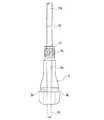
図2〜図5は本発明のパンク修理液の回収装置を構成するチューブを示すものである。図2に示すように、チューブ10の途中にはチューブ10よりも外径が大きくタイヤバルブ3に対して嵌合可能な封止部11が設けられている。より具体的には、封止部11はチューブ10よりも太いパイプ材で構成され、チューブ10に対してその長手方向に摺動自在に取り付けられている。そのため、封止部11をチューブ10の長手方向に沿って摺動させることにより、タイヤサイズに応じてチューブ10の挿入部分10aの長さを調整することができる。なお、封止部11はチューブ10に対して摺動自在であることが望ましいが、チューブ10に対して一体的に成形したものであっても良い。 2 to 5 show a tube constituting the puncture repair liquid recovery apparatus of the present invention. As shown in FIG. 2, a sealing
図3に示すように、タイヤバルブ3は内部に円筒状の貫通孔3a(破線にて図示)を有すると共に、その基端側にはホイール2の取り付け穴に対して係合する括れ部3bが形成され、その先端側には雄ねじ部3cが形成されている。貫通孔3aは長手方向の一部が局部的に絞り込まれていて当該部位に内径が最小となる最細部3dが形成されている。内圧充填時において、タイヤバルブ3にはバルブコアが挿入される。 As shown in FIG. 3, the tire valve 3 has a cylindrical through
上記タイヤバルブ3の構造に鑑みて、チューブ10の外径はタイヤバルブ3の貫通孔3aの最細部3dの内径よりも小さくなっており、封止部11の外径はタイヤバルブ3の貫通孔3aの最細部3dの内径よりも大きくなっている。また、タイヤバルブ用のキャップ5の頂部にチューブ10が挿入される小穴を形成し、チューブ10を封止部1と共にタイヤバルブ3内に挿入した状態でキャップ5をタイヤバルブ3に締め込むようにした場合、キャップ5により封止部11をタイヤバルブ3内に押し込むことができる。 In view of the structure of the tire valve 3, the outer diameter of the
このようにチューブ10の途中にチューブ10よりも外径が大きくタイヤバルブ3内に嵌合可能な封止部11を設け、タイヤ1内のパンク修理液4を回収する際に封止部11をタイヤバルブ3に嵌め込むことにより、チューブ10とタイヤバルブ3との間の隙間から空気が漏れることを防止し、パンク修理液4の回収作業を効率良く行うことができる。なお、気密性を高めるために封止部11をタイヤバルブ3に向かって先細りとなる楔形状としても良い。 As described above, the sealing
チューブ10の材質は、特に限定されるものではないが、シリコーンゴム等のゴム、ポリプロピレン、ポリエチレン、ポリウレタン、ポリアミド、フッ素樹脂等の合成樹脂、金属等を使用することができる。チューブ10の差し込み作業性を考慮すると、ポリエチレンやポリウレタンが好ましい。 The material of the
チューブ10のタイヤ内に挿入する部分の長さは150mm以上で、好ましくは、150mm〜250mmの範囲にすると良い。これは、タイヤサイズによって適正長さが異なるためである。チューブ10のタイヤ外側部分の長さは、作業性を考慮すると50mm〜300mm程度が好ましい。従って、チューブ10の全長は200mm〜550mm程度になる。チューブ10は、タイヤ内に挿入する量が短い場合はもちろん、長過ぎてもタイヤ内のチューブ端部が適正位置に収まらないため、パンク修理液4の排出作業が難しくなる。 The length of the portion of the
チューブ10の外径は2.5mm〜3.0mmの範囲にすると良い。チューブ10が太過ぎるとチューブ10をタイヤバルブ3内に通すことが難しくなり、逆に細過ぎるとパンク修理液4の排出に多大な時間を要することになる。また、チューブ10の内径をその外径の50%〜90%の範囲にすると良い。これにより、チューブ10にある程度の剛性を与えてタイヤバルブ3への挿入の容易さを確保しながらパンク修理液4の排出効率を高めることができる。チューブ10の内径が小さ過ぎるとパンク修理液4の排出効率が低下し、逆に大き過ぎるとチューブ10が過度に柔らかくなるためタイヤバルブ3への挿入が難しくなる。例えば、チューブ10の内径は上記外径に対して1.5mm〜2.0mmの範囲に設定することができる。 The outer diameter of the
一方、封止部11の外径は3.2mm〜4.0mmの範囲にすると良い。封止部11が太過ぎると封止部11をタイヤバルブ3内に押し込むことが難しくなり、逆に細過ぎると気密性を確保することが難しくなる。 On the other hand, the outer diameter of the sealing
図4(a)〜(b)に示すように、チューブ10は封止部11の位置をアルファベットA〜Cにて指示する目盛り12を具備し、該目盛り12に基づいて封止部11の位置をタイヤサイズに応じて選択するようになっている。つまり、チューブ10の長さとしては想定される全てのタイヤについて適用可能な寸法が設定されており、目盛り12に基づいて封止部11の位置を適宜選択することにより、各種タイヤサイズに適応するようになっている。図4(a)においては、目盛り12がチューブ10に直接表示されている。図4(b)においては、目盛り12が紙等からなるシート13に印刷されている。目盛り12が印刷されるシート13は専用のものであっても良いが、取扱説明書の一部を利用しても良い。いずれの場合も目盛り12の意味は取扱説明書等に記載されるものとする。例えば、取扱説明書には目盛り12のアルファベットA〜Cとタイヤサイズとの対応関係が表示される。目盛り12は、線の太さ、色、本数等を異ならせることで区別可能としたり、上述のアルファベットに替えて数字や記号等を付記するようにしても良い。 As shown in FIGS. 4A to 4B, the
上述のように封止部11の位置を変位させる替わりに、図5(a)〜(b)に示すように、チューブ10は切断長さをアルファベットX〜Zにて指示する目盛り12’を具備し、該目盛り12’に基づいてチューブ10をタイヤサイズに応じて切断するようにしても良い。つまり、使用前のチューブ10の長さとしては想定される全てのタイヤについてタイヤバルブ3からタイヤ1の内面まで届くような寸法が設定されており、目盛り12’に基づいてチューブ10を適宜切断することにより、各種タイヤサイズに適応するようになっている。図5(a)においては、目盛り12’がチューブ10に直接表示されている。図5(b)においては、目盛り12’が紙等からなるシート13’に印刷されている。目盛り12’が印刷されるシート13’は専用のものであっても良いが、取扱説明書の一部を利用しても良い。いずれの場合も目盛り12’の意味は取扱説明書等に記載されるものとする。例えば、取扱説明書には目盛り12’のアルファベットX〜Zとタイヤサイズとの対応関係が表示される。目盛り12’は、線の太さ、色、本数等を異ならせることで区別可能としたり、上述のアルファベットに替えて数字や記号等を付記するようにしても良い。 Instead of displacing the position of the sealing
図6(a)〜(b)は本発明のパンク修理液の回収装置を構成するチューブに装着される飛散防止部材を示すものである。前述の手順によりタイヤ1内からのパンク修理液4の回収が概ね完了した状態になると、チューブ10の端部からはパンク修理液4と共に残留空気が排出され、その結果、チューブ10の端部からパンク修理液4が飛散する恐れがある。そこで、チューブ10のタイヤ外側の端部にはチューブ10よりも内径が大きい飛散防止部材14を装着すると良い。 FIGS. 6A to 6B show a scattering prevention member attached to a tube constituting the puncture repair liquid recovery apparatus of the present invention. When the recovery of the puncture repair liquid 4 from the inside of the tire 1 is almost completed by the above procedure, residual air is discharged from the end of the
図6(a)において、チューブ10のタイヤ外側の端部にはチューブ10の外径と等しい内径を有する円筒状の飛散防止部材14が装着されている。図6(b)において、チューブ10のタイヤ外側の端部にはチューブ10の外径よりも大きい内径を有する円筒状の飛散防止部材14が装着されている。 In FIG. 6A, a cylindrical
飛散防止部材14の内径は、例えば、チューブ10の内径より大きくすれば良く、より具体的には、チューブ10の内径の1.5倍以上とするのが良い。飛散防止部材14の内径が前記範囲から外れると飛散防止効果が不十分になる。また、飛散防止部材14の長さ(チューブ10の端部からの長さ)は、例えば、100mm以上とするのが良い。飛散防止部材14が短過ぎると飛散防止効果が不十分になる。 For example, the inner diameter of the
図7は本発明のパンク修理液の回収装置を構成する他のチューブを示すものである。図7においては、チューブ10に対して該チューブ10よりも外径が大きくタイヤバルブの外側に配置される延長チューブ10Xが接続されている。そして、延長チューブ10Xのタイヤバルブ3側の端部がタイヤバルブ3に対して嵌合可能な封止部11を構成している。この場合、延長チューブ10Xと一体的に形成された封止部11はチューブ10に対してその長手方向に摺動自在になっている。そのため、封止部11をチューブ10の長手方向に沿って摺動させることにより、タイヤサイズに応じてチューブ10の挿入部分10aの長さを調整することができる。 FIG. 7 shows another tube constituting the puncture repair liquid recovery device of the present invention. In FIG. 7, an
このようにチューブ10に対して延長チューブ10Xを接続した場合も、上述の実施形態と同様にして、タイヤ1内の残留圧力を利用してタイヤ1内のパンク修理液4を回収することができる。 Even when the
上述した実施形態において、パンク修理液4はチューブ10を介して回収されるが、回収用の容器としては、バケツやボトル等の他に、可撓性を有する袋を使用することができる。そして、可撓性を有する袋の中で凝固剤によりパンク修理液4を凝固させることが好ましい。 In the above-described embodiment, the puncture repair liquid 4 is collected through the
図8〜図10は本発明で使用される凝固剤を封入した可撓性を有する袋を示すものである。図8に示すように、本実施形態に係るパンク修理液の回収装置は、パンク修理液を凝固させるための凝固剤30と、パンク修理液を収容するための可撓性を有する袋40とを備えている。 8 to 10 show a flexible bag enclosing a coagulant used in the present invention. As shown in FIG. 8, the puncture repair liquid recovery apparatus according to the present embodiment includes a
凝固剤30は、エマルション粒子を含有するパンク修理液を凝固させるものであれば、特に限定されるものではなく、例えば、特開2009−41006号公報に記載の凝固剤を使用することができる。この凝固剤はエマルション粒子の凝集を引き起こす鉱物とゲル化剤とを含有するものである。 The
上記鉱物としては、ケイ酸塩、酸化物及び炭酸塩からなる群から選ばれた少なくとも1種を使用することができる。例えば、鉱物として、アルミナ、ケイ酸ナトリウム、ケイ酸マグネシウム、ケイ酸アルミニウム、モンモリロナイト、ベントナイト及びゼオライトからなる群から選ばれた少なくとも1種を使用すると良い。 As said mineral, at least 1 sort (s) chosen from the group which consists of a silicate, an oxide, and carbonate can be used. For example, as the mineral, at least one selected from the group consisting of alumina, sodium silicate, magnesium silicate, aluminum silicate, montmorillonite, bentonite, and zeolite may be used.
一方、ゲル化剤としては、ポリエチレンオキシド、ポリプロピレンオキシド、ヒドロキシエチルセルロース及びこれらの変性ポリマー、アルギン酸ナトリウム、アルギン酸プロピレングリコール並びにジベンジリデンソルビトールからなる群から選ばれた少なくとも1種を使用すると良い。 On the other hand, as the gelling agent, at least one selected from the group consisting of polyethylene oxide, polypropylene oxide, hydroxyethyl cellulose and their modified polymers, sodium alginate, propylene glycol alginate and dibenzylidene sorbitol may be used.
ゲル化剤の量は、鉱物100重量部に対して、20〜700重量部、好ましくは、60〜200重量部であると良い。但し、上記凝固剤は、鉱物及びゲル化剤の他に、必要に応じて、例えば、充填剤、老化防止剤、酸化防止剤、顔料(染料)、可塑剤、揺変性付与剤、紫外線吸収剤、難燃剤、界面活性剤、分散剤、脱水剤、帯電防止剤等の添加剤を含有することができる。 The amount of the gelling agent is 20 to 700 parts by weight, preferably 60 to 200 parts by weight with respect to 100 parts by weight of the mineral. However, the coagulant may be, for example, a filler, an anti-aging agent, an antioxidant, a pigment (dye), a plasticizer, a thixotropic agent, an ultraviolet absorber, in addition to the mineral and the gelling agent. Further, additives such as a flame retardant, a surfactant, a dispersant, a dehydrating agent, and an antistatic agent can be contained.
一方、可撓性を有する袋40は、ラミネートフィルム44からなる2枚の側シート41,42とラミネートフィルム44からなる1枚のマチ43とを互いに熱融着して形成されている。袋40の中には予め凝固剤30が封入されている。また、袋40はタイヤ内から回収されるパンク修理液を収容するために700ml〜2000mlの容量を有することが望ましい。マチ43は袋40の下部に配置されている。マチ43は未使用時には折り畳まれた状態になっているが、常時開いた状態であっても良い。いずれにしても、袋40はマチ43を広げた状態において立体的な形状をなして自立する構造になっている。 On the other hand, the
ラミネートフィルム44は、図9に示すように、ガスバリア性を有する中間層44aと、中間層44aの内側に積層された内層44bと、中間層44aの外側に積層された外層44cとを含んでいる。中間層44aの構成材料としては、エチレン・ビニルアルコール共重合体(EVOH)、ポリアミド(PA)、ポリ塩化ビニリデン(PVDC)、ポリビニルアルコール(PVA)、MXナイロン(MXD6)、ポリアクリロニトリル樹脂(PAN)等の気体透過性が低い合成樹脂の他、アルミ箔等の金属箔を使用することができる。一方、内層44b及び外層44cの構成材料としては、機械的強度や耐候性を確保するために、ポリエチレン、ポリエステル、ナイロン等の合成樹脂を使用することができる。内層44bと外層44cとは同一の材料から構成することが好ましいが、その要求特性に応じて互いに異なる材料から構成しても良い。 As shown in FIG. 9, the laminate film 44 includes an intermediate layer 44a having a gas barrier property, an inner layer 44b laminated inside the intermediate layer 44a, and an outer layer 44c laminated outside the intermediate layer 44a. . The constituent material of the intermediate layer 44a includes ethylene / vinyl alcohol copolymer (EVOH), polyamide (PA), polyvinylidene chloride (PVDC), polyvinyl alcohol (PVA), MX nylon (MXD6), and polyacrylonitrile resin (PAN). In addition to a synthetic resin having a low gas permeability such as a metal foil such as an aluminum foil can be used. On the other hand, as a constituent material of the inner layer 44b and the outer layer 44c, a synthetic resin such as polyethylene, polyester, or nylon can be used in order to ensure mechanical strength and weather resistance. The inner layer 44b and the outer layer 44c are preferably made of the same material, but may be made of different materials depending on the required characteristics.
中間層44aの厚さは、合成樹脂の場合、5μm〜200μmにすると良い。アルミ箔等の金属箔の場合、1nm〜500nm、好ましくは5nm〜200nmにするのが良い。中間層44aが薄過ぎるとガスバリア性が低下し、逆に厚過ぎると可撓性が低下する要因となる。また、内層44b及び外層44cの各々の厚さは5μm〜100μmにする良い。これら内層44b及び外層44cが薄過ぎるとパンク修理液と凝固剤とを混合する際の耐久性が低下し、逆に厚過ぎると可撓性が低下することになる。 In the case of synthetic resin, the thickness of the intermediate layer 44a is preferably 5 μm to 200 μm. In the case of a metal foil such as an aluminum foil, the thickness may be 1 nm to 500 nm, preferably 5 nm to 200 nm. If the intermediate layer 44a is too thin, the gas barrier property is lowered. Conversely, if the intermediate layer 44a is too thick, the flexibility is lowered. The thickness of each of the inner layer 44b and the outer layer 44c may be 5 μm to 100 μm. If the inner layer 44b and the outer layer 44c are too thin, the durability when mixing the puncture repair liquid and the coagulant is lowered, and conversely if it is too thick, the flexibility is lowered.
なお、内層44b及び外層44cは、それぞれ1層でも良いし、異なる材料からなる複数層でも良い。複数層の場合、その合計厚さが5μm〜100μmになるようにすると良い。 Each of the inner layer 44b and the outer layer 44c may be a single layer or a plurality of layers made of different materials. In the case of a plurality of layers, the total thickness is preferably 5 μm to 100 μm.
袋40の側縁の上部には切り口45が設けられており、この切り口45を起点として袋40の上端部分が引き裂かれることで開口部46(図10参照)が形成されるようになっている。そして、袋40には開口部46に沿って封止帯47が設けられている。封止帯47は、開口部46を封止可能であれば、その構造が特に限定されるものではないが、例えば、一方の側シート41において開口部46に沿って延在する溝47aと、他方の側シート42において開口部46に沿って延在すると共に溝47aに対して弾性的に嵌合する突条47bとから構成することができる。 An opening 45 (see FIG. 10) is formed by tearing the upper end portion of the
上述した凝固剤30及び袋40を用いてパンク修理液4を回収する場合、図10に示すように、凝固剤30を内包している袋40の上端を開口し、その中にタイヤ1内から抜き取られたパンク修理液4を投入する。次いで、袋40の開口部46を封止帯47により封止した後、可撓性を有する袋40を揉んでパンク修理液4と凝固剤30とを混合することにより、袋40の中でパンク修理液4を凝固させる。その結果、使用済みのパンク修理液4は袋40と一緒に可燃ゴミとして簡単かつ速やかに廃棄することが可能になる。 When recovering the puncture repair liquid 4 using the
上述したパンク修理液の回収方法においては、可撓性を有する袋40の開口部46に封止帯47を設けているので、袋40を揉むときにパンク修理液4が溢れるのを確実に防止することができる。 In the puncture repair liquid recovery method described above, the sealing
また、可撓性を有する袋40はガスバリア性を有する中間層44aを含むラミネートフィルム44からなり、袋40の中に予め凝固剤30が封入されているので、内包された凝固剤30は空気に晒されることはなく品質を長期間にわたって維持することができる。 The
更に、袋40は下部にマチ43を有していて自立する構造であるので、パンク修理液4をタイヤ1内から抜き取る際に袋40を支える必要がない。そのため、パンク修理液4をタイヤ1内から抜き取る際にチューブ等の操作が必要となる場合であっても、全ての回収作業を一人で行うことができるという利点がある。 Furthermore, since the
上述した実施形態においては、可撓性を有する袋がガスバリア性を有する中間層を含むラミネートフィルムからなり、その袋の中に予め凝固剤が封入されている場合について説明したが、本発明では、可撓性を有する袋として軟質のビニール袋等を使用し、凝固剤はガスバリア性を有する他のパッケージに封入されていても良い。その場合、可撓性を有する袋の中にパンク修理液と共に凝固剤を投入し、それらパンク修理液と凝固剤とを混合すれば良い。 In the embodiment described above, the case where the flexible bag is made of a laminate film including an intermediate layer having a gas barrier property and the coagulant is enclosed in advance in the bag has been described. A soft plastic bag or the like may be used as the flexible bag, and the coagulant may be enclosed in another package having gas barrier properties. In that case, a coagulant may be introduced into the flexible bag together with the puncture repair liquid, and the puncture repair liquid and the coagulant may be mixed.
1 空気入りタイヤ
2 ホイール
3 タイヤバルブ
4 パンク修理液
5 キャップ
10 チューブ
10a 挿入部分
10b 突出部分
10X 延長チューブ
11 封止部
12,12’ 目盛り
13,13’ シート
14 飛散防止部材
20 容器
30 凝固剤
40 袋DESCRIPTION OF SYMBOLS 1
Claims (19)
Translated fromJapanesePriority Applications (7)
| Application Number | Priority Date | Filing Date | Title |
|---|---|---|---|
| JP2010259492AJP5229306B2 (en) | 2010-11-19 | 2010-11-19 | Puncture repair liquid recovery method and recovery device |
| US13/885,780US8950443B2 (en) | 2010-11-19 | 2011-06-09 | Method for recovering puncture repair liquid and apparatus for recovering puncture repair liquid |
| KR1020137015709AKR101391129B1 (en) | 2010-11-19 | 2011-06-09 | Method for recovering puncture repair solution and recovery device |
| CN201180055122.5ACN103209820B (en) | 2010-11-19 | 2011-06-09 | The recovery method of tire sealant liquid and retracting device |
| EP11842091.8AEP2641729B1 (en) | 2010-11-19 | 2011-06-09 | Method for recovering puncture repair solution |
| RU2013127651/05ARU2522104C1 (en) | 2010-11-19 | 2011-06-09 | Method and device for fluid removal at puncture elimination |
| PCT/JP2011/063222WO2012066811A1 (en) | 2010-11-19 | 2011-06-09 | Method for recovering puncture repair solution and recovery device |
Applications Claiming Priority (1)
| Application Number | Priority Date | Filing Date | Title |
|---|---|---|---|
| JP2010259492AJP5229306B2 (en) | 2010-11-19 | 2010-11-19 | Puncture repair liquid recovery method and recovery device |
Publications (2)
| Publication Number | Publication Date |
|---|---|
| JP2012111054A JP2012111054A (en) | 2012-06-14 |
| JP5229306B2true JP5229306B2 (en) | 2013-07-03 |
Family
ID=46083756
Family Applications (1)
| Application Number | Title | Priority Date | Filing Date |
|---|---|---|---|
| JP2010259492AExpired - Fee RelatedJP5229306B2 (en) | 2010-11-19 | 2010-11-19 | Puncture repair liquid recovery method and recovery device |
Country Status (7)
| Country | Link |
|---|---|
| US (1) | US8950443B2 (en) |
| EP (1) | EP2641729B1 (en) |
| JP (1) | JP5229306B2 (en) |
| KR (1) | KR101391129B1 (en) |
| CN (1) | CN103209820B (en) |
| RU (1) | RU2522104C1 (en) |
| WO (1) | WO2012066811A1 (en) |
Families Citing this family (1)
| Publication number | Priority date | Publication date | Assignee | Title |
|---|---|---|---|---|
| US20140373974A1 (en)* | 2013-06-24 | 2014-12-25 | Brandon Ragan | Pouch-type Sealant Injector |
Family Cites Families (21)
| Publication number | Priority date | Publication date | Assignee | Title |
|---|---|---|---|---|
| US2222047A (en)* | 1938-04-06 | 1940-11-19 | Goodrich Co B F | Apparatus for removing liquid from tires |
| US4700531A (en)* | 1984-07-20 | 1987-10-20 | American Can Company | Method of forming a package having strong seals and a modified ply-separation opening |
| JPH06560B2 (en)* | 1988-04-15 | 1994-01-05 | 株式会社タツノ・メカトロニクス | Water remover |
| RU2012505C1 (en)* | 1991-06-03 | 1994-05-15 | Воронежский шинный завод | Method of repair of injured types |
| DE19625372B4 (en)* | 1996-06-25 | 2006-05-24 | Sumitomo Rubber Industries Ltd., Kobe | Method of removing puncture sealants from tires and apparatus for carrying out the method |
| US6464697B1 (en)* | 1998-02-19 | 2002-10-15 | Curon Medical, Inc. | Stomach and adjoining tissue regions in the esophagus |
| JPH11222244A (en)* | 1998-02-02 | 1999-08-17 | Hosokawa Yoko:Kk | Pharmaceutical and medical gusset bag |
| US6481645B1 (en)* | 2000-05-22 | 2002-11-19 | Shurflo Pump Mfg. Company, Inc. | Condiment dispensing nozzle apparatus and method |
| JP3782333B2 (en) | 2001-10-22 | 2006-06-07 | 住友ゴム工業株式会社 | Sealing agent injection / extraction hose and tire repair method using the same |
| EP1502873A4 (en)* | 2002-04-17 | 2009-08-12 | Toppan Printing Co Ltd | PACKAGING MATERIAL AND PACKAGING BAG |
| JP3782385B2 (en)* | 2002-09-26 | 2006-06-07 | 住友ゴム工業株式会社 | Sealing agent injection / extraction hose set |
| JP2005138400A (en)* | 2003-11-06 | 2005-06-02 | Bridgestone Corp | Sealant recovery apparatus |
| WO2005116115A1 (en)* | 2004-05-26 | 2005-12-08 | Bridgestone Corporation | Method of disposing of sealing agent and sealing agent disposal apparatus |
| CN100489017C (en)* | 2004-05-26 | 2009-05-20 | 株式会社普利司通 | Method of disposing sealing agent and sealing agent disposal apparatus |
| US7621304B2 (en)* | 2006-05-05 | 2009-11-24 | Nielsen Idaho Tool & Engineering Corporation | Closeable self-venting spout |
| US9555931B2 (en)* | 2006-06-07 | 2017-01-31 | Reynolds Consumer Products LLC | Slider bag with handle below the zipper track |
| JP2007331210A (en)* | 2006-06-14 | 2007-12-27 | Bridgestone Corp | Device for recovering sealant |
| US7745511B2 (en) | 2007-07-17 | 2010-06-29 | The Yokohama Rubber Co., Ltd. | Emulsion coagulant |
| JP2009090862A (en)* | 2007-10-10 | 2009-04-30 | Bridgestone Corp | Tire/rim assembly, tire valve, and sealant recovering method |
| JP2009090574A (en)* | 2007-10-10 | 2009-04-30 | Bridgestone Corp | Method for collecting sealing agent |
| JP2010259492A (en) | 2009-04-30 | 2010-11-18 | Topcon Corp | Fundus observation device |
- 2010
- 2010-11-19JPJP2010259492Apatent/JP5229306B2/ennot_activeExpired - Fee Related
- 2011
- 2011-06-09EPEP11842091.8Apatent/EP2641729B1/enactiveActive
- 2011-06-09USUS13/885,780patent/US8950443B2/enactiveActive
- 2011-06-09WOPCT/JP2011/063222patent/WO2012066811A1/enactiveApplication Filing
- 2011-06-09RURU2013127651/05Apatent/RU2522104C1/enactive
- 2011-06-09KRKR1020137015709Apatent/KR101391129B1/ennot_activeExpired - Fee Related
- 2011-06-09CNCN201180055122.5Apatent/CN103209820B/enactiveActive
Also Published As
| Publication number | Publication date |
|---|---|
| CN103209820A (en) | 2013-07-17 |
| US20130233404A1 (en) | 2013-09-12 |
| JP2012111054A (en) | 2012-06-14 |
| US8950443B2 (en) | 2015-02-10 |
| RU2522104C1 (en) | 2014-07-10 |
| CN103209820B (en) | 2015-10-21 |
| EP2641729B1 (en) | 2016-03-23 |
| KR20130111589A (en) | 2013-10-10 |
| WO2012066811A1 (en) | 2012-05-24 |
| EP2641729A1 (en) | 2013-09-25 |
| KR101391129B1 (en) | 2014-05-02 |
| EP2641729A4 (en) | 2014-08-06 |
Similar Documents
| Publication | Publication Date | Title |
|---|---|---|
| JP4743326B2 (en) | How to recover puncture repair liquid | |
| JP4743325B2 (en) | Puncture repair liquid recovery method and recovery device | |
| JP4743328B2 (en) | Puncture repair liquid recovery method and recovery device | |
| JP3782333B2 (en) | Sealing agent injection / extraction hose and tire repair method using the same | |
| CN102712146B (en) | Method and device for recovering tire blowout repair fluid | |
| JP4743327B2 (en) | Puncture repair liquid recovery method and recovery device | |
| JP5229306B2 (en) | Puncture repair liquid recovery method and recovery device | |
| JP5177208B2 (en) | How to recover puncture repair liquid | |
| JP3782385B2 (en) | Sealing agent injection / extraction hose set | |
| JP5304928B1 (en) | Tire cleaning method | |
| CN109049765B (en) | Tire repair liquid bottle | |
| JP2010000683A (en) | Method for recovering sealant and jig |
Legal Events
| Date | Code | Title | Description |
|---|---|---|---|
| A621 | Written request for application examination | Free format text:JAPANESE INTERMEDIATE CODE: A621 Effective date:20120418 | |
| A871 | Explanation of circumstances concerning accelerated examination | Free format text:JAPANESE INTERMEDIATE CODE: A871 Effective date:20121115 | |
| A975 | Report on accelerated examination | Free format text:JAPANESE INTERMEDIATE CODE: A971005 Effective date:20121129 | |
| A131 | Notification of reasons for refusal | Free format text:JAPANESE INTERMEDIATE CODE: A131 Effective date:20121211 | |
| A521 | Request for written amendment filed | Free format text:JAPANESE INTERMEDIATE CODE: A523 Effective date:20130122 | |
| TRDD | Decision of grant or rejection written | ||
| A01 | Written decision to grant a patent or to grant a registration (utility model) | Free format text:JAPANESE INTERMEDIATE CODE: A01 Effective date:20130219 | |
| A61 | First payment of annual fees (during grant procedure) | Free format text:JAPANESE INTERMEDIATE CODE: A61 Effective date:20130304 | |
| FPAY | Renewal fee payment (event date is renewal date of database) | Free format text:PAYMENT UNTIL: 20160329 Year of fee payment:3 | |
| R150 | Certificate of patent or registration of utility model | Ref document number:5229306 Country of ref document:JP Free format text:JAPANESE INTERMEDIATE CODE: R150 Free format text:JAPANESE INTERMEDIATE CODE: R150 | |
| R250 | Receipt of annual fees | Free format text:JAPANESE INTERMEDIATE CODE: R250 | |
| R250 | Receipt of annual fees | Free format text:JAPANESE INTERMEDIATE CODE: R250 | |
| R250 | Receipt of annual fees | Free format text:JAPANESE INTERMEDIATE CODE: R250 | |
| R250 | Receipt of annual fees | Free format text:JAPANESE INTERMEDIATE CODE: R250 | |
| R250 | Receipt of annual fees | Free format text:JAPANESE INTERMEDIATE CODE: R250 | |
| R250 | Receipt of annual fees | Free format text:JAPANESE INTERMEDIATE CODE: R250 | |
| LAPS | Cancellation because of no payment of annual fees |