JP5225996B2 - Endoscopic vessel sealer and divider with flexible articulation shaft - Google Patents
Endoscopic vessel sealer and divider with flexible articulation shaftDownload PDFInfo
- Publication number
- JP5225996B2 JP5225996B2JP2009531474AJP2009531474AJP5225996B2JP 5225996 B2JP5225996 B2JP 5225996B2JP 2009531474 AJP2009531474 AJP 2009531474AJP 2009531474 AJP2009531474 AJP 2009531474AJP 5225996 B2JP5225996 B2JP 5225996B2
- Authority
- JP
- Japan
- Prior art keywords
- shaft
- tissue
- housing
- drive rod
- assembly
- Prior art date
- Legal status (The legal status is an assumption and is not a legal conclusion. Google has not performed a legal analysis and makes no representation as to the accuracy of the status listed.)
- Active
Links
- 210000001519tissueAnatomy0.000description147
- 239000012636effectorSubstances0.000description75
- 238000007789sealingMethods0.000description53
- 238000000034methodMethods0.000description22
- 210000004204blood vesselAnatomy0.000description19
- 230000000712assemblyEffects0.000description15
- 238000000429assemblyMethods0.000description15
- 238000001356surgical procedureMethods0.000description15
- 230000007246mechanismEffects0.000description14
- 238000005520cutting processMethods0.000description13
- 230000008878couplingEffects0.000description12
- 238000010168coupling processMethods0.000description12
- 238000005859coupling reactionMethods0.000description12
- 230000002792vascularEffects0.000description11
- 230000004913activationEffects0.000description10
- 238000001994activationMethods0.000description10
- 239000000463materialSubstances0.000description8
- 230000008901benefitEffects0.000description7
- PXHVJJICTQNCMI-UHFFFAOYSA-NNickelChemical compound[Ni]PXHVJJICTQNCMI-UHFFFAOYSA-N0.000description6
- 238000006073displacement reactionMethods0.000description6
- 230000006870functionEffects0.000description6
- 238000002674endoscopic surgeryMethods0.000description5
- 230000004044responseEffects0.000description5
- 230000006835compressionEffects0.000description4
- 238000007906compressionMethods0.000description4
- 239000002783friction materialSubstances0.000description3
- 230000014759maintenance of locationEffects0.000description3
- 230000008569processEffects0.000description3
- 241001631457CannulaSpecies0.000description2
- 210000003815abdominal wallAnatomy0.000description2
- 210000003484anatomyAnatomy0.000description2
- 210000000436anusAnatomy0.000description2
- 238000005452bendingMethods0.000description2
- 230000000740bleeding effectEffects0.000description2
- 238000006243chemical reactionMethods0.000description2
- 230000015271coagulationEffects0.000description2
- 238000005345coagulationMethods0.000description2
- 238000000576coating methodMethods0.000description2
- 230000008021depositionEffects0.000description2
- 230000000994depressogenic effectEffects0.000description2
- 238000012976endoscopic surgical procedureMethods0.000description2
- 238000005516engineering processMethods0.000description2
- 230000008713feedback mechanismEffects0.000description2
- 238000010304firingMethods0.000description2
- 238000010438heat treatmentMethods0.000description2
- 229910001055inconels 600Inorganic materials0.000description2
- 238000002347injectionMethods0.000description2
- 239000007924injectionSubstances0.000description2
- 239000012212insulatorSubstances0.000description2
- 238000007912intraperitoneal administrationMethods0.000description2
- 238000004519manufacturing processMethods0.000description2
- 229910052751metalInorganic materials0.000description2
- 239000002184metalSubstances0.000description2
- 229910052759nickelInorganic materials0.000description2
- 238000002355open surgical procedureMethods0.000description2
- 210000003200peritoneal cavityAnatomy0.000description2
- 230000002980postoperative effectEffects0.000description2
- 238000000926separation methodMethods0.000description2
- 210000002784stomachAnatomy0.000description2
- 238000013519translationMethods0.000description2
- 206010002091AnaesthesiaDiseases0.000description1
- 208000032544CicatrixDiseases0.000description1
- 206010053567CoagulopathiesDiseases0.000description1
- 102000008186CollagenHuman genes0.000description1
- 108010035532CollagenProteins0.000description1
- 229910000599Cr alloyInorganic materials0.000description1
- 206010028980NeoplasmDiseases0.000description1
- 229910000990Ni alloyInorganic materials0.000description1
- 229910018487Ni—CrInorganic materials0.000description1
- 229910000831SteelInorganic materials0.000description1
- 208000007536ThrombosisDiseases0.000description1
- 229910010037TiAlNInorganic materials0.000description1
- ATJFFYVFTNAWJD-UHFFFAOYSA-NTinChemical compound[Sn]ATJFFYVFTNAWJD-UHFFFAOYSA-N0.000description1
- 230000009471actionEffects0.000description1
- 230000003213activating effectEffects0.000description1
- WYTGDNHDOZPMIW-RCBQFDQVSA-NalstonineNatural productsC1=CC2=C3C=CC=CC3=NC2=C2N1C[C@H]1[C@H](C)OC=C(C(=O)OC)[C@H]1C2WYTGDNHDOZPMIW-RCBQFDQVSA-N0.000description1
- 230000037005anaesthesiaEffects0.000description1
- 238000010171animal modelMethods0.000description1
- 210000001367arteryAnatomy0.000description1
- SJKRCWUQJZIWQB-UHFFFAOYSA-Nazane;chromiumChemical compoundN.[Cr]SJKRCWUQJZIWQB-UHFFFAOYSA-N0.000description1
- 230000009286beneficial effectEffects0.000description1
- 239000008280bloodSubstances0.000description1
- 210000004369bloodAnatomy0.000description1
- 201000011510cancerDiseases0.000description1
- 229910010293ceramic materialInorganic materials0.000description1
- 230000008859changeEffects0.000description1
- 238000002192cholecystectomyMethods0.000description1
- 239000011651chromiumSubstances0.000description1
- 239000000788chromium alloySubstances0.000description1
- VNNRSPGTAMTISX-UHFFFAOYSA-Nchromium nickelChemical compound[Cr].[Ni]VNNRSPGTAMTISX-UHFFFAOYSA-N0.000description1
- 230000007012clinical effectEffects0.000description1
- 230000035602clottingEffects0.000description1
- 230000001112coagulating effectEffects0.000description1
- 229920001436collagenPolymers0.000description1
- 210000001072colonAnatomy0.000description1
- 238000004891communicationMethods0.000description1
- 239000004020conductorSubstances0.000description1
- 238000007796conventional methodMethods0.000description1
- 238000013461designMethods0.000description1
- 238000003745diagnosisMethods0.000description1
- 238000002405diagnostic procedureMethods0.000description1
- 238000009792diffusion processMethods0.000description1
- 238000001035dryingMethods0.000description1
- 230000000694effectsEffects0.000description1
- 210000003238esophagusAnatomy0.000description1
- 230000004927fusionEffects0.000description1
- 210000000232gallbladderAnatomy0.000description1
- 230000002496gastric effectEffects0.000description1
- 208000021302gastroesophageal reflux diseaseDiseases0.000description1
- 210000001035gastrointestinal tractAnatomy0.000description1
- 230000023597hemostasisEffects0.000description1
- 238000001746injection mouldingMethods0.000description1
- 208000014674injuryDiseases0.000description1
- 239000011810insulating materialSubstances0.000description1
- 210000000936intestineAnatomy0.000description1
- 210000003734kidneyAnatomy0.000description1
- 238000012317liver biopsyMethods0.000description1
- 230000013011matingEffects0.000description1
- 238000012986modificationMethods0.000description1
- 230000004048modificationEffects0.000description1
- 210000003205muscleAnatomy0.000description1
- CLDVQCMGOSGNIW-UHFFFAOYSA-Nnickel tinChemical compound[Ni].[Sn]CLDVQCMGOSGNIW-UHFFFAOYSA-N0.000description1
- 150000004767nitridesChemical class0.000description1
- 210000000056organAnatomy0.000description1
- 210000001672ovaryAnatomy0.000description1
- 210000003101oviductAnatomy0.000description1
- 230000037361pathwayEffects0.000description1
- 230000002093peripheral effectEffects0.000description1
- 230000002028prematureEffects0.000description1
- 230000000750progressive effectEffects0.000description1
- 238000011084recoveryMethods0.000description1
- 239000011819refractory materialSubstances0.000description1
- 231100000241scarToxicity0.000description1
- 230000037387scarsEffects0.000description1
- 125000006850spacer groupChemical group0.000description1
- 238000010911splenectomyMethods0.000description1
- 239000007921spraySubstances0.000description1
- 238000005507sprayingMethods0.000description1
- 239000010935stainless steelSubstances0.000description1
- 229910001220stainless steelInorganic materials0.000description1
- 239000010959steelSubstances0.000description1
- 230000002459sustained effectEffects0.000description1
- 238000002560therapeutic procedureMethods0.000description1
- 230000000451tissue damageEffects0.000description1
- 231100000827tissue damageToxicity0.000description1
- 238000012546transferMethods0.000description1
- 230000008733traumaEffects0.000description1
- 210000004291uterusAnatomy0.000description1
- 210000001215vaginaAnatomy0.000description1
- 230000000007visual effectEffects0.000description1
- 238000011179visual inspectionMethods0.000description1
Images


Classifications
- A—HUMAN NECESSITIES
- A61—MEDICAL OR VETERINARY SCIENCE; HYGIENE
- A61B—DIAGNOSIS; SURGERY; IDENTIFICATION
- A61B18/00—Surgical instruments, devices or methods for transferring non-mechanical forms of energy to or from the body
- A61B18/04—Surgical instruments, devices or methods for transferring non-mechanical forms of energy to or from the body by heating
- A61B18/12—Surgical instruments, devices or methods for transferring non-mechanical forms of energy to or from the body by heating by passing a current through the tissue to be heated, e.g. high-frequency current
- A61B18/14—Probes or electrodes therefor
- A61B18/1442—Probes having pivoting end effectors, e.g. forceps
- A61B18/1445—Probes having pivoting end effectors, e.g. forceps at the distal end of a shaft, e.g. forceps or scissors at the end of a rigid rod
- A—HUMAN NECESSITIES
- A61—MEDICAL OR VETERINARY SCIENCE; HYGIENE
- A61B—DIAGNOSIS; SURGERY; IDENTIFICATION
- A61B17/00—Surgical instruments, devices or methods
- A61B17/28—Surgical forceps
- A61B17/29—Forceps for use in minimally invasive surgery
- A—HUMAN NECESSITIES
- A61—MEDICAL OR VETERINARY SCIENCE; HYGIENE
- A61B—DIAGNOSIS; SURGERY; IDENTIFICATION
- A61B17/00—Surgical instruments, devices or methods
- A61B17/28—Surgical forceps
- A61B17/29—Forceps for use in minimally invasive surgery
- A61B17/295—Forceps for use in minimally invasive surgery combined with cutting implements
- A—HUMAN NECESSITIES
- A61—MEDICAL OR VETERINARY SCIENCE; HYGIENE
- A61B—DIAGNOSIS; SURGERY; IDENTIFICATION
- A61B18/00—Surgical instruments, devices or methods for transferring non-mechanical forms of energy to or from the body
- A61B18/04—Surgical instruments, devices or methods for transferring non-mechanical forms of energy to or from the body by heating
- A61B18/12—Surgical instruments, devices or methods for transferring non-mechanical forms of energy to or from the body by heating by passing a current through the tissue to be heated, e.g. high-frequency current
- A61B18/14—Probes or electrodes therefor
- A61B18/1492—Probes or electrodes therefor having a flexible, catheter-like structure, e.g. for heart ablation
- A—HUMAN NECESSITIES
- A61—MEDICAL OR VETERINARY SCIENCE; HYGIENE
- A61B—DIAGNOSIS; SURGERY; IDENTIFICATION
- A61B17/00—Surgical instruments, devices or methods
- A61B17/00234—Surgical instruments, devices or methods for minimally invasive surgery
- A61B2017/00292—Surgical instruments, devices or methods for minimally invasive surgery mounted on or guided by flexible, e.g. catheter-like, means
- A61B2017/003—Steerable
- A—HUMAN NECESSITIES
- A61—MEDICAL OR VETERINARY SCIENCE; HYGIENE
- A61B—DIAGNOSIS; SURGERY; IDENTIFICATION
- A61B18/00—Surgical instruments, devices or methods for transferring non-mechanical forms of energy to or from the body
- A61B2018/00571—Surgical instruments, devices or methods for transferring non-mechanical forms of energy to or from the body for achieving a particular surgical effect
- A61B2018/00619—Welding
- A—HUMAN NECESSITIES
- A61—MEDICAL OR VETERINARY SCIENCE; HYGIENE
- A61B—DIAGNOSIS; SURGERY; IDENTIFICATION
- A61B18/00—Surgical instruments, devices or methods for transferring non-mechanical forms of energy to or from the body
- A61B2018/0091—Handpieces of the surgical instrument or device
- A61B2018/00916—Handpieces of the surgical instrument or device with means for switching or controlling the main function of the instrument or device
- A61B2018/00922—Handpieces of the surgical instrument or device with means for switching or controlling the main function of the instrument or device by switching or controlling the treatment energy directly within the hand-piece
- A—HUMAN NECESSITIES
- A61—MEDICAL OR VETERINARY SCIENCE; HYGIENE
- A61B—DIAGNOSIS; SURGERY; IDENTIFICATION
- A61B18/00—Surgical instruments, devices or methods for transferring non-mechanical forms of energy to or from the body
- A61B18/04—Surgical instruments, devices or methods for transferring non-mechanical forms of energy to or from the body by heating
- A61B18/12—Surgical instruments, devices or methods for transferring non-mechanical forms of energy to or from the body by heating by passing a current through the tissue to be heated, e.g. high-frequency current
- A61B18/14—Probes or electrodes therefor
- A61B18/1442—Probes having pivoting end effectors, e.g. forceps
- A61B2018/1452—Probes having pivoting end effectors, e.g. forceps including means for cutting
- A61B2018/1455—Probes having pivoting end effectors, e.g. forceps including means for cutting having a moving blade for cutting tissue grasped by the jaws
Landscapes
- Health & Medical Sciences (AREA)
- Surgery (AREA)
- Engineering & Computer Science (AREA)
- Life Sciences & Earth Sciences (AREA)
- Biomedical Technology (AREA)
- Otolaryngology (AREA)
- Nuclear Medicine, Radiotherapy & Molecular Imaging (AREA)
- Plasma & Fusion (AREA)
- Physics & Mathematics (AREA)
- Heart & Thoracic Surgery (AREA)
- Medical Informatics (AREA)
- Molecular Biology (AREA)
- Animal Behavior & Ethology (AREA)
- General Health & Medical Sciences (AREA)
- Public Health (AREA)
- Veterinary Medicine (AREA)
- Surgical Instruments (AREA)
Description
Translated fromJapanese(関連出願の引用)
本出願は、米国仮特許出願第60/850,214号(2006年10月6日出願、出願人:Eric Taylor他、名称「ENDOSCOPIC VESSEL SEALER AND DIVIDER HAVING A FLEXIBLE ARTICULATING SHAFT」)に基づく優先権の利益を主張する。この仮出願の内容は、参照により本明細書に引用される。(Citation of related application)
This application is based on US Provisional Patent Application No. 60 / 850,214 (filed Oct. 6, 2006, Applicant: Eric Taylor et al., “ENDOSCOPIC VESSEL SEALER AND DIVIDER HAVING A FLEXIBLE ARTICLATING SHAFT”). Insist on profit. The contents of this provisional application are incorporated herein by reference.
(技術分野)
本発明は、電気外科鉗子に関し、より具体的には、本発明は、細長く、略可撓性、かつ関節運動型のシャフトを利用した、組織を封着および/または切断するための内視鏡電気外科鉗子に関する。(Technical field)
The present invention relates to electrosurgical forceps, and more particularly, the present invention relates to an endoscope for sealing and / or cutting tissue utilizing an elongated, generally flexible, articulating shaft. The present invention relates to electrosurgical forceps.
電気外科鉗子は、組織を凝固する、焼灼させるおよび/または封着するために、組織および血管を加熱することにより止血させる機械的締め付け作用および電気エネルギーの両方を利用する。開口外科手技で使用するための開口鉗子の代替として、現代の外科医の多くは、より小さな穿刺様切開を介して器官に遠隔でアクセスするための内視鏡および内視鏡器具を使用する。その直接的な結果として、患者は、少ない瘢痕および治癒にかかる時間の減少の利益を享受する傾向がある。 Electrosurgical forceps utilize both mechanical clamping action and electrical energy to hemostasis by heating tissue and blood vessels to coagulate, cauterize and / or seal tissue. As an alternative to open forceps for use in open surgical procedures, many modern surgeons use endoscopes and endoscopic instruments for remotely accessing organs through smaller puncture-like incisions. As a direct result, patients tend to enjoy the benefits of fewer scars and reduced time to heal.
概して、内視鏡手術は、体壁を介して切開すること、例えば、卵巣、子宮、胆嚢、腸、腎臓、虫垂等を観察および/または手術することを含む。ほんの数例を挙げると、関節鏡検査、腹腔鏡検査(骨盤鏡検査)、胃腸鏡検査および喉頭気管支鏡検査を含む、多くの一般的な内視鏡外科手技がある。典型的に、トロカールは、それを介して内視鏡手術が行われる切開を生成するために使用される。 In general, endoscopic surgery involves making an incision through the body wall, for example, observing and / or operating on the ovary, uterus, gallbladder, intestine, kidney, appendix, and the like. There are many common endoscopic surgical procedures, including arthroscopy, laparoscopic (pelvicoscopy), gastrointestinal and laryngobronchioscopy, to name just a few. Typically, a trocar is used to create an incision through which endoscopic surgery is performed.
トロカール管またはカニューレ装置は、内視鏡手術道具のアクセスを提供するために、腹壁内に延在され、そこに留置される。カメラまたは内視鏡は、概してネーバル切開部にあり、体腔の目視検査および拡大を可能にする比較的大直径のトロカール管を介して挿入される。次いで、外科医は、付加的なカニューレを通り抜けるように設計された鉗子、カッター、アプリケータ等の特殊計装を活用して、手術部位における診断および治療手技を行うことができる。したがって、主要な筋肉を介して切断する大切開(典型的には、12インチ以上)の代わりに、内視鏡手術を受ける患者は、サイズ5から10ミリメータのより美容的に有利な切開を受け入れる。したがって、回復はより早急であり、患者は従来の手術よりも麻酔をあまり必要としない。さらに、手術野が大きく拡大するために、外科医は、より上手に、血管を切開し、失血を制御することができる。 A trocar tube or cannula device is extended into and placed in the abdominal wall to provide endoscopic surgical tool access. The camera or endoscope is generally at the naval incision and is inserted through a relatively large diameter trocar tube that allows visual inspection and enlargement of the body cavity. The surgeon can then take advantage of special instrumentation such as forceps, cutters, applicators and the like designed to pass through additional cannulas to perform diagnostic and therapeutic procedures at the surgical site. Thus, instead of a large incision (typically 12 inches or more) that cuts through the main muscles, patients undergoing endoscopic surgery accept a more cosmetically advantageous incision of size 5 to 10 millimeters . Therefore, recovery is quicker and patients require less anesthesia than conventional surgery. In addition, because the surgical field is greatly expanded, surgeons can better incise blood vessels and control blood loss.
手術の外傷を減少するための継続的な努力の中で、現在では、標的組織にアクセスするために、自然の開口部(例えば、口または肛門)を使用して、腹壁におけるいかなる切開もなく病状を診断および外科的に治療するための手技を行う可能性への関心が高まっている。そのような手技は、場合によっては、管腔内手技、経腔的手技、または自然開口部経腔的内視鏡手術(natural orifice transluminal endoscopic surgery:「NOTES」)と称される。そのような管腔内手技の多くは依然として開発されているが、それらは、概して、標的組織へのアクセスを提供するために、可撓性内視鏡器具または可撓性カテーテルを利用する。管腔内手技は、例えば、食道における胃食道逆流症の治療ならびに結腸からのポリープの除去を含む、管腔内の状態を治療するために使用されている。一部の場合において、医師は、消化管の管腔境界の範囲を超え、腹腔内手技を行う。例えば、可撓性内視鏡器具使用手段を使用して、種々の手技を行うために、胃壁を穿刺することができ、内視鏡を腹膜腔内に前進させることができる。 In ongoing efforts to reduce surgical trauma, the condition is now without any incision in the abdominal wall, using natural openings (eg mouth or anus) to access the target tissue There is a growing interest in the possibility of performing procedures for the diagnosis and surgical treatment of cancer. Such procedures are sometimes referred to as intraluminal procedures, transluminal procedures, or natural orifice transluminal endoscopic surgery ("NOTES"). Although many such endoluminal procedures are still being developed, they generally utilize flexible endoscopic instruments or flexible catheters to provide access to the target tissue. Intraluminal procedures have been used to treat intraluminal conditions, including, for example, treatment of gastroesophageal reflux disease in the esophagus as well as removal of polyps from the colon. In some cases, the physician goes beyond the luminal boundary of the gastrointestinal tract and performs an intraperitoneal procedure. For example, the flexible endoscopic instrument using means can be used to puncture the stomach wall to perform various procedures, and the endoscope can be advanced into the peritoneal cavity.
そのような管腔内技術を使用して、診断的探索、肝生検、胆嚢摘出術、脾摘出術、および卵管結紮が動物モデルにおいて行われていると報告されている。腹腔内治療介入の完了後、内視鏡器具使用手段は、胃内へ縮退し、穿刺は閉鎖される。また、肛門または腟等の他の自然開口部は、腹膜腔へのアクセスを可能にし得る。 Using such intraluminal techniques, diagnostic exploration, liver biopsy, cholecystectomy, splenectomy, and fallopian tube ligation have been reported in animal models. After completing the intraperitoneal intervention, the endoscopic instrument use means retracts into the stomach and the puncture is closed. In addition, other natural openings such as the anus or vagina may allow access to the peritoneal cavity.
上記のように、多くの内視鏡および管腔内外科手技は、典型的に、血管または血管組織を切断または結紮する必要がある。しかしながら、これにより、内視鏡器具がより小さなカニューレを通り抜けられるようにする方法を探らなければならない器具製造業者に対して、最終的に設計上の課題が提示される。外科的空洞の生来の空間的考慮に起因して、外科医は、血管を縫合するか、または例えば、切断された血管を締め付けるおよび/または結紮する等の出血を制御する他の従来の方法を行うことが困難であることが多い。内視鏡電気外科鉗子を利用することによって、外科医は、顎部材を介して組織に印加される電気外科的エネルギーの強度、周波数および持続時間を単に制御することによって、出血を焼灼させる、凝固させる/乾燥させるおよび/または単に減少させるまたは遅くすることができる。大部分の小血管、つまり、直径で2ミリメータ未満の範囲にあるものは、標準的な電気外科器具および技術を使用して閉鎖することができる。しかしながら、より大きな血管が結紮されるのであれば、外科医は、内視鏡的手技を開口外科手技に転換し、それによって内視鏡手術の利点を放棄する必要があり得る。あるいは、外科医は、特殊な血管封着器具を利用して、より大きな血管または組織を封着することができる。 As noted above, many endoscopes and endoluminal surgical procedures typically require cutting or ligating blood vessels or vascular tissue. However, this ultimately presents design challenges to instrument manufacturers who must explore ways to allow endoscopic instruments to pass through smaller cannulas. Due to the natural spatial considerations of the surgical cavity, the surgeon sutures the blood vessel or performs other conventional methods of controlling bleeding such as, for example, tightening and / or ligating the cut blood vessel Is often difficult. By utilizing endoscopic electrosurgical forceps, surgeons cauterize and coagulate bleeding by simply controlling the intensity, frequency and duration of electrosurgical energy applied to tissue via the jaw members / Can be dried and / or simply reduced or slowed down. Most small blood vessels, ie those in the range of less than 2 millimeters in diameter, can be closed using standard electrosurgical instruments and techniques. However, if larger blood vessels are ligated, the surgeon may need to convert the endoscopic procedure to an open surgical procedure, thereby abandoning the benefits of endoscopic surgery. Alternatively, the surgeon can utilize a special vascular sealing instrument to seal larger blood vessels or tissues.
血管を凝固させる過程は、本質的には、電気外科的血管封着とは異なると考えられる。本明細書においては、「凝固」は、組織細胞が破裂または乾燥される組織を乾燥させる過程として定義される。「血管封着」または「組織封着」は、それが融合した塊に再編成できるように、組織中のコラーゲンを液化する過程として定義される。小血管の凝固は、それらを持続的に閉鎖させるのに十分であり、一方で、より大きな血管は、持続性閉鎖を保証するように封着される必要がある。さらに、大きな組織または血管の凝固は、低破裂強度を有する悪評高い弱い近位血栓をもたらし、一方で、組織封着は、比較的高破裂強度を有し、組織封着平面に沿って効果的に切断され得る。 The process of coagulating blood vessels is considered to be essentially different from electrosurgical vascular sealing. As used herein, “clotting” is defined as the process of drying tissue where tissue cells are ruptured or dried. “Vessel sealing” or “tissue sealing” is defined as the process of liquefying the collagen in tissue so that it can be reorganized into a fused mass. Coagulation of small blood vessels is sufficient to keep them permanently closed, while larger blood vessels need to be sealed to ensure sustained closure. In addition, large tissue or blood vessel coagulation results in a notoriously weak proximal thrombus with low burst strength, while tissue sealing has a relatively high burst strength and is effective along the tissue sealing plane Can be cut into pieces.
より具体的には、より大きな血管(または組織)を効果的に封着するために、2つの主な機械的パラメータは正確に制御され、この2つの主な機械的パラメータは、血管(または組織)に印加される圧力と電極間の間隙距離とであり、封着血管の厚さの影響をどちらも受ける。より具体的には、圧力の正確な印加は、血管壁に対抗するために、組織を介して十分な電気外科的エネルギーを可能にするのに十分なほど低い値まで組織インピーダンスを減少させるために、組織加熱時の膨張力を克服するために、ならびに良好な封着の指標である端部組織の厚さに寄与するために重要である。典型的な融合血管壁は、0.001から0.006インチが最適であると決定されている。この範囲未満では、封着は切断または分裂される場合があり、この範囲を超える場合では、管腔は適切にまたは効果的に封着されない場合がある。 More specifically, in order to effectively seal larger blood vessels (or tissues), the two main mechanical parameters are precisely controlled, and the two main mechanical parameters are the blood vessels (or tissues). ) And the gap distance between the electrodes, both affected by the thickness of the sealed blood vessel. More specifically, accurate application of pressure to reduce tissue impedance to a value low enough to allow sufficient electrosurgical energy through the tissue to counter the vessel wall. It is important to overcome the expansion force during tissue heating and to contribute to the thickness of the end tissue, which is an indicator of good sealing. A typical fusion vessel wall has been determined to be optimal between 0.001 and 0.006 inches. Below this range, the seal may be cut or split, and beyond this range, the lumen may not be properly or effectively sealed.
より小さな血管に関しては、組織に印加された圧力は、あまり関連性がなくなる傾向があり、一方、導電性表面間の間隙距離は、効果的な封着に対してより重要となる。言い換えれば、2つの導電性表面が起動時に触れる可能性は、血管が小さくなるにつれて増加する。 For smaller blood vessels, the pressure applied to the tissue tends to become less relevant, while the gap distance between the conductive surfaces becomes more important for effective sealing. In other words, the likelihood that two conductive surfaces will touch upon activation increases as the blood vessels become smaller.
一貫したおよび効果的な封着を保証するための圧力範囲は、約3kg/cm2から約16kg/cm2であり、望ましくは、7kg/cm2から13kg/cm2の動作範囲内にあることが分かっている。この動作範囲内の閉鎖圧を提供することが可能な器具を製造することは、動脈、組織および他の血管束を封着するのに効果的であることが示されている。The pressure range to ensure consistent and effective sealing is from about 3 kg / cm2 to about 16 kg / cm2 , preferably within the operating range of 7 kg / cm2 to 13 kg / cm2 I know. Manufacturing an instrument capable of providing a closure pressure within this operating range has been shown to be effective in sealing arteries, tissues and other vascular bundles.
血管封着をもたらすのに適切な閉鎖力を提供するために、種々の加力アセンブリが過去に開発されている。例えば、共有に係る米国仮特許出願、特許文献1および特許文献2は、商標LIGASURE(登録商標)に基づき一般的に販売されているValleylabの血管封着および分割器具とともに使用するための、Tyco Healthcare LPの部門であるBoulder,ColoradのValleylab,Inc.が開発した2つの異なる企図された作動アセンブリを開示する。これらの出願の両方の内容は、参照することによりそれら全体が本願明細書に組み込まれる。 Various force assemblies have been developed in the past to provide a suitable closure force to provide a vascular seal. For example, the co-owned US Provisional Patent Application, US Pat. Nos. 5,057,086 and 5,037,397 are a Tyco Healthcare for use with Valleylab's vascular sealing and splitting devices commonly sold under the trademark LIGASURE®. LP department, Boulder, Colorado, Valleylab, Inc. Discloses two different contemplated actuating assemblies. The contents of both of these applications are hereby incorporated by reference in their entirety.
使用中における外科医の1つの顕著な課題は、信頼性のある血管封着をもたらす上記の必要な力を生じつつ、複数の平面内の、つまり軸外(off−axis)の組織を保持するために、血管シーラのエンドエフェクタアセンブリを操作することができないことである。したがって、外科医が、外科的空洞内の異なる平面に沿って位置する血管を保持および封着することを可能にする複数の軸に沿って操作することが可能なエンドエフェクタアセンブリを含む、内視鏡的または管腔内血管封着器具を開発することが所望されるであろう。 One significant challenge for surgeons in use is to maintain multiple in-plane or off-axis tissue while producing the necessary force described above that results in reliable vessel sealing. In addition, the end effector assembly of the vascular sealer cannot be manipulated. Thus, an endoscope that includes an end effector assembly that can be manipulated along multiple axes that allow a surgeon to hold and seal blood vessels located along different planes within the surgical cavity. It would be desirable to develop a mechanical or intraluminal vessel sealing device.
管腔内手技は、時折、可撓性カテーテルまたは内視鏡を使用して、自然管腔の蛇行状の解剖学的形態深部の組織にアクセスする必要がある。従来の血管封着装置は、自然管腔の蛇行状の解剖学的形態を容易には通り抜けることができない硬いシャフトのために、一部の管腔内手技での使用に適切でない場合がある。したがって、可撓性内視鏡またはカテーテルを挿入することが可能な可撓性シャフトを有する内視鏡的または管腔内血管封着器具を開発することが所望されるであろう。 Intraluminal procedures sometimes require access to deep tissue tortuous anatomical forms of natural lumens using flexible catheters or endoscopes. Conventional vascular sealing devices may not be suitable for use in some endoluminal procedures because of the rigid shaft that cannot easily pass through the serpentine anatomy of the natural lumen. Accordingly, it would be desirable to develop an endoscopic or intraluminal vessel sealing device having a flexible shaft into which a flexible endoscope or catheter can be inserted.
本発明は、シャフトを介して画定される軸A−Aを有する、ハウジングから延在する可撓性シャフトを有するハウジングを含む、組織を治療するための電気外科器具に関する。該シャフトは、その遠位端に取り付けられた第1および第2の顎部材を含み、各顎部材は、電気外科的エネルギー源に接続するように適合された導電性組織接触面を含む。電気的に起動されると、導電性組織接触面は、顎部材間で保持された組織を介して電気外科的エネルギーを伝導する。駆動アセンブリは、該ハウジング内に位置し、駆動ロッドの往復運動のために該駆動ロッドに操作可能に連結された第1のアクチュエータと、駆動ロッドの回転のために該駆動ロッドに操作可能に連結された第2のアクチュエータとを含む。ナイフが含まれ、該駆動ロッドの遠位端に操作可能に連結される。該第1のアクチュエータの作動は、組織を係合するために、該顎部材を、互いに対して離間した第1の位置から互いに近接した第2の位置に移動させる。該第2のアクチュエータの作動は、該顎部材間に配置された組織を切断するナイフを平行移動させるために、該軸A−Aの周りで該駆動ロッドを回転させる。 The present invention relates to an electrosurgical instrument for treating tissue, including a housing having a flexible shaft extending from the housing having an axis A-A defined through the shaft. The shaft includes first and second jaw members attached to its distal end, each jaw member including a conductive tissue contacting surface adapted to connect to an electrosurgical energy source. When electrically activated, the conductive tissue contacting surface conducts electrosurgical energy through the tissue held between the jaw members. A drive assembly is located within the housing and is operably coupled to the drive rod for rotation of the drive rod with a first actuator operably coupled to the drive rod for reciprocal movement of the drive rod Second actuator. A knife is included and operably connected to the distal end of the drive rod. Actuation of the first actuator moves the jaw members from a first position spaced relative to one another to a second position proximate one another to engage tissue. Actuation of the second actuator rotates the drive rod about the axis AA to translate a knife that cuts tissue disposed between the jaw members.
一実施形態において、該鉗子は、該駆動ロッドの遠位端に連結されたカムアセンブリを含む。該カムアセンブリは、該ナイフ上に配置された対応する戻り止めを嵌合係合するように構成されたその中に画定された溝のついた外周辺を有するカムハブを含む。該駆動ロッドの回転運動は、対応して該カムハブを回転させ、次に、該顎部材に対して該戻り止めおよびナイフを平行移動させる。連結装置、例えば、係止ロッドは、一方の端で、該駆動ロッドと連動するように構成され、反対端で、該カムハブ内において画定される鍵状開口部を嵌合係合するように構成される。 In one embodiment, the forceps includes a cam assembly coupled to the distal end of the drive rod. The cam assembly includes a cam hub having a grooved outer periphery defined therein configured to matingly engage corresponding detents disposed on the knife. The rotational movement of the drive rod correspondingly rotates the cam hub and then translates the detent and knife relative to the jaw members. A coupling device, such as a locking rod, is configured to interlock with the drive rod at one end and to engage and engage a key-like opening defined within the cam hub at the opposite end. Is done.
別の実施形態において、該可撓性シャフトは、該可撓性シャフトの少なくとも一部を形成するように入れ子のように直列に配列された複数の接合部を含む。各接合部は、その中の該駆動ロッドの往復運動を可能にするように、それを介して画定される少なくとも1つの管腔を含んでもよい。一実施形態において、各接合部は、その中に形成される中心管腔と、該中心管腔の両側に形成される1対の対向管腔とを含む。該電気外科器具は、軸A−Aに対して該シャフトを関節運動させるために互いに対して可動の、該それぞれの対向管腔を介して摺動自在に延在可能な1対の関節運動ケーブルを含んでもよい。 In another embodiment, the flexible shaft includes a plurality of joints that are nested and arranged in series to form at least a portion of the flexible shaft. Each joint may include at least one lumen defined therethrough to allow reciprocation of the drive rod therein. In one embodiment, each junction includes a central lumen formed therein and a pair of opposing lumens formed on opposite sides of the central lumen. The electrosurgical instrument is a pair of articulation cables slidably extendable through the respective opposing lumens movable relative to each other to articulate the shaft relative to an axis A-A May be included.
さらに別の実施形態において、軸A−Aに対して該可撓性シャフトを関節運動させるために、互いに対して1対の関節運動ケーブルを移動させる該ハウジングに操作可能に連結された第3のアクチュエータが含まれてもよい。 In yet another embodiment, a third operably coupled to the housing that moves a pair of articulation cables relative to each other to articulate the flexible shaft relative to axis AA. An actuator may be included.
また、本発明は、シャフトを介して画定される軸A−Aを有する、ハウジングから延在する可撓性シャフトを有するハウジングを含む、組織を治療するための電気外科器具にも関する。エンドエフェクタアセンブリは、該顎部材が互いに対して可動となるように、旋回ピンの周りで第1および第2の顎部材を支持するためのクレビスを含む該シャフトの遠位端に取り付けられる。各顎部材は、導電性組織接触面が、それらの間に保持された組織を介して電気外科的エネルギーを伝導することができるように、該電気外科的エネルギー源に接続するように適合された導電性組織接触面を含む。該顎部材はそれぞれ、その中に画定される傾斜カム表面を含み、該クレビスは、その中に画定されるスロットを含む。ナイフは、該駆動ロッドの遠位端に操作可能に連結され、駆動アセンブリは、該ハウジング内に配置される。該駆動ロッドアセンブリは、駆動ロッドの往復運動のために該駆動ロッドに操作可能に連結された第1のアクチュエータと、駆動ロッドの回転のために該駆動ロッドに操作可能に連結された第2のアクチュエータとを含む。該第1のアクチュエータの作動が、組織を係合するために、該顎部材を、互いに対して離間した第1の位置から互いに近接した第2の位置に移動させる該駆動ロッドを往復運動させ、該第2のアクチュエータの作動が、該顎部材の間に配置された組織を切断するために、該ナイフを平行移動させるように軸A−Aの周りで該駆動ロッドを回転させるように、該駆動ロッドの遠位端は、該顎部材内に画定される該カム表面と該クレビス内に画定される該スロットとの両方を係合する駆動ピンを受け入れるように構成される。 The present invention also relates to an electrosurgical instrument for treating tissue, including a housing having a flexible shaft extending from the housing having an axis A-A defined through the shaft. An end effector assembly is attached to the distal end of the shaft including clevises for supporting the first and second jaw members about the pivot pin so that the jaw members are movable relative to each other. Each jaw member is adapted to connect to the electrosurgical energy source such that the conductive tissue contacting surface can conduct electrosurgical energy through the tissue held therebetween. Includes a conductive tissue contacting surface. Each of the jaw members includes an inclined cam surface defined therein, and the clevis includes a slot defined therein. A knife is operably coupled to the distal end of the drive rod, and the drive assembly is disposed within the housing. The drive rod assembly includes a first actuator operably coupled to the drive rod for reciprocal movement of the drive rod and a second actuator operably coupled to the drive rod for rotation of the drive rod. Including an actuator. Actuation of the first actuator reciprocates the drive rod that moves the jaw members from a first position spaced relative to each other to a second position proximate to each other to engage tissue; Actuating the second actuator to rotate the drive rod about axis A-A to translate the knife to cut tissue disposed between the jaw members; The distal end of the drive rod is configured to receive a drive pin that engages both the cam surface defined in the jaw member and the slot defined in the clevis.
一実施形態において、カムアセンブリは、その中に画定される溝のついた外周辺を有するカムハブを含む、該駆動ロッドの遠位端に連結される。該溝のついた外周辺は、該ナイフ上に配置される対応する戻り止めを嵌合係合するように構成され、該駆動ロッドの回転運動は、対応して該カムハブを回転させ、次に、該顎部材に対して該戻り止めとナイフを平行移動させる。該駆動ロッドは、駆動ロードの軸方向運動が該ナイフを往復運動させないように、該カムハブ内で摺動自在に受け入れられる。 In one embodiment, the cam assembly is coupled to the distal end of the drive rod including a cam hub having a grooved outer periphery defined therein. The grooved outer periphery is configured to matingly engage a corresponding detent disposed on the knife, and the rotational movement of the drive rod correspondingly rotates the cam hub and then The detent and knife are translated relative to the jaw member. The drive rod is slidably received within the cam hub so that axial movement of the drive load does not reciprocate the knife.
また、本発明は、シャフトを介して画定される軸A−Aを有する、ハウジングから延在するシャフトを有するハウジングを含む、組織を治療するための電気外科器具にも関する。該シャフトは、少なくとも部分的に可撓性であり、その遠位端に取り付けられた第1および第2の顎部材を含む。各顎部材は、導電性組織接触面が、それらの間に保持された組織を介して電気外科的エネルギーを伝導することができるように、該電気外科的エネルギー源に接続するように適合された導電性組織接触面を含む。駆動アセンブリは、該ハウジング内に配置され、組織を係合するために、該顎部材を、互いに対して離間した第1の位置から互いに近接する第2の位置に移動させるために、可撓性駆動ロッドの往復運動のために該可撓性駆動ロッドに操作可能に連結される第1のアクチュエータを有する。第2のアクチュエータは、該ハウジング上に配置され、該シャフトを関節運動するように作動可能である。 The present invention also relates to an electrosurgical instrument for treating tissue, including a housing having a shaft extending from the housing having an axis A-A defined through the shaft. The shaft is at least partially flexible and includes first and second jaw members attached to its distal end. Each jaw member is adapted to connect to the electrosurgical energy source such that the conductive tissue contacting surface can conduct electrosurgical energy through the tissue held therebetween. Includes a conductive tissue contacting surface. A drive assembly is disposed within the housing and is flexible to move the jaw members from a first position spaced relative to one another to a second position proximate to one another to engage tissue. A first actuator is operably coupled to the flexible drive rod for reciprocal movement of the drive rod. A second actuator is disposed on the housing and is operable to articulate the shaft.
一実施形態において、該シャフトの可撓性部分は、入れ子のように直列に配列された複数の接合部を含む。各接合部は、その中の該駆動ロッドおよび関節運動ケーブルの往復運動を可能とするために、それを介して画定される1つ以上の管腔を含むように構成されてもよい。 In one embodiment, the flexible portion of the shaft includes a plurality of joints arranged in series like a nest. Each joint may be configured to include one or more lumens defined therethrough to allow reciprocation of the drive rod and articulation cable therein.
一実施形態において、該第2のアクチュエータは、該シャフトを介して該関節運動ケーブルを往復運動させるための滑車システムに動作可能に連結される、該ハウジング上に配置される1つ以上のユーザが作動可能な構成部品(例えば、ホイール)を有する関節運動アセンブリを含む。また、該関節運動アセンブリは、該1対の関節運動ケーブルを該滑車システム内に方向付け、該関節運動ケーブルを事前緊張するための1つ以上のガイドを含んでもよい。 In one embodiment, the second actuator is provided by one or more users disposed on the housing operatively coupled to a pulley system for reciprocating the articulation cable via the shaft. An articulation assembly having actuable components (eg, wheels). The articulation assembly may also include one or more guides for directing the pair of articulation cables into the pulley system and pre-tensioning the articulation cables.
別の実施形態において、該駆動アセンブリは、駆動ロッドに操作可能に連結される4棒機械的連携部を含み、該4棒機械的連携部の作動は、組織を係合するために、該顎部材を、互いに対して離間した第1の位置から互いに近接する第2の位置に移動させる該駆動ロッドを往復運動させる。 In another embodiment, the drive assembly includes a four-bar mechanical linkage operably coupled to the drive rod, the actuation of the four-bar mechanical linkage being configured to engage the tissue to engage the jaws. The drive rod is reciprocated to move the member from a first position spaced from each other to a second position adjacent to each other.
さらに別の実施形態において、調整アクチュエータは、製造業者が、該第1の位置に配置された際の該顎部材の相対距離を調整することを可能にする該駆動ロッドに連結される。
例えば、本発明は以下を提供する。
(項目1)
組織を治療するための電気外科器具であって、
シャフトを有するハウジングであって、
上記シャフトは、上記ハウジングから延在し、上記シャフトを通り画定される軸A−Aを有し、上記シャフトは、少なくとも部分的に可撓性であり、その遠位端に取り付けられた第1および第2の顎部材を含み、各顎部材は、導電性組織接触面が、それらの間に保持された組織を介して電気外科的エネルギーを伝導することができるように、上記電気外科的エネルギー源に接続するように適合された導電性組織接触面を含む、ハウジングと、
上記ハウジング内に配置された駆動アセンブリであって、上記駆動アセンブリは、駆動ロッドの往復運動のために上記駆動ロッドに操作可能に連結された第1のアクチュエータを含み、上記第1のアクチュエータの作動は、上記駆動ロッドを往復運動させ、それは、次に、組織を係合するために上記顎部材を互いに対して離間した第1の位置から互いに近接した第2の位置に移動させる、駆動アセンブリと、
上記シャフトを関節運動するように作動可能である、上記ハウジング上に配置された第2のアクチュエータと
を備える、組織を治療するための電気外科器具。
(項目2)
上記シャフトの可撓性部分は、入れ子のように直列に配列された複数の接合部を含む、項目1に記載の組織を治療するための電気外科器具。
(項目3)
各接合部は、その中の上記駆動ロッドの往復運動を可能にするように、それを介して画定される少なくとも1つの管腔を含む、項目2に記載の組織を治療するための電気外科器具。
(項目4)
各接合部は、その中に形成される中心管腔と、上記中心管腔の両側に形成される1対の対向管腔とを含み、上記電気外科器具は、軸A−Aに対して上記シャフトの上記可撓性部分を関節運動させるために互いに対して可動の、上記それぞれの対向管腔を介して摺動自在に延在可能な1対の関節運動ケーブルを含む、項目2に記載の組織を治療するための電気外科器具。
(項目5)
上記駆動ロッドは、可撓性である、項目1に記載の組織を治療するための電気外科器具。
(項目6)
上記第2のアクチュエータは、上記シャフトを介して摺動自在に延在可能な1対の関節運動ケーブルを往復運動させるための滑車システムに動作可能に連結される、上記ハウジング上に配置される少なくとも1つのユーザが作動可能な構成部品を有する関節運動アセンブリを含む、項目1に記載の組織を治療するための電気外科器具。
(項目7)
上記関節運動アセンブリは、上記1対の関節運動ケーブルを上記滑車システム内に方向付け、上記関節運動ケーブルを事前緊張するための少なくとも1つのガイドを含む、項目6に記載の組織を治療するための電気外科器具。
(項目8)
組織を治療するための電気外科器具であって、
シャフトを有するハウジングであって、
上記シャフトは、上記ハウジングから延在し、上記シャフトを通り画定される軸A−Aを有し、上記シャフトは、少なくとも部分的に可撓性であり、その遠位端に取り付けられた第1および第2の顎部材を含み、各顎部材は、導電性組織接触面が、それらの間に保持された組織を介して電気外科的エネルギーを伝導することができるように、上記電気外科的エネルギー源に接続するように適合された導電性組織接触面を含む、ハウジングと、 上記ハウジング内に配置された駆動アセンブリであって、上記駆動アセンブリは、駆動ロッドの往復運動のために上記駆動ロッドに操作可能に連結された4棒機械的連携部を含み、上記4棒機械的連携部の作動は、上記駆動ロッドを往復運動させ、それは、次に、組織を係合するために上記顎部材を互いに対して離間した第1の位置から互いに近接した第2の位置に移動させる、駆動アセンブリと、
上記シャフトを関節運動するように作動可能である、上記ハウジング上に配置された第2のアクチュエータと
を備える、組織を治療するための電気外科器具。
(項目9)
組織を治療するための電気外科器具であって、
シャフトを有するハウジングであって、
上記シャフトは、上記ハウジングから延在し、上記シャフトを通り画定される軸A−Aを有し、上記シャフトは、少なくとも部分的に可撓性であり、その遠位端に取り付けられた第1および第2の顎部材を含み、各顎部材は、導電性組織接触面が、それらの間に保持された組織を介して電気外科的エネルギーを伝導することができるように、上記電気外科的エネルギー源に接続するように適合された導電性組織接触面を含む、ハウジングと、
駆動ロッドの往復運動のために上記駆動ロッドに操作可能に連結された駆動アセンブリを含む上記ハウジング内に配置された駆動アセンブリであって、
上記駆動アセンブリの作動は、上記駆動ロッドを往復運動させ、それは、次に、組織を係合するために上記顎部材を互いに対して離間した第1の位置から互いに近接する第2の位置に移動させる、駆動アセンブリと、
上記シャフトを関節運動するように作動可能である上記ハウジング上に配置された第2のアクチュエータと、
上記駆動ロットに連結される調整アクチュエータであって、
調整アクチュエータは、製造業者が、上記第1の位置に配置される際の上記顎部材の相対距離を調節することを可能にする、調整アクチュエータと
を備える、組織を治療するための電気外科器具。
(項目10)
上記シャフトの可撓性部分は、上記可撓性シャフトの少なくとも一部を形成するように、入れ子のように直列に配列された複数の接合部を含み、各接合部は、その中に形成された中心管腔と、上記中心管腔の両側に形成される1対の対向管腔とを含み、上記電気外科器具は、軸A−Aに対して上記シャフトを関節運動させるために互いに対して可動の、上記それぞれの対向管腔を介して摺動自在に延在可能な1対の関節運動ケーブルを含む、項目9に記載の組織を治療するための電気外科器具。
(項目11)
上記第2のアクチュエータは、上記シャフトを介して摺動自在に延在可能な1対の関節運動ケーブルを往復運動させるための滑車システムに動作可能に連結される、上記ハウジング上に配置される少なくとも1つのユーザが作動可能な構成部品を有する関節運動アセンブリを含む、項目9に記載の組織を治療するための電気外科器具。
(項目12)
上記関節運動アセンブリは、上記1対の関節運動ケーブルを上記滑車システム内に方向付け、上記関節運動ケーブルを事前緊張するための少なくとも1つのガイドを含む、項目11に記載の組織を治療するための電気外科器具。
In yet another embodiment, an adjustment actuator is coupled to the drive rod that allows a manufacturer to adjust the relative distance of the jaw members when placed in the first position.
For example, the present invention provides the following.
(Item 1)
An electrosurgical instrument for treating tissue,
A housing having a shaft,
The shaft extends from the housing and has an axis A-A defined through the shaft, the shaft being at least partially flexible and attached to a distal end thereof. And a second jaw member, each jaw member including the electrosurgical energy such that the conductive tissue contacting surface can conduct electrosurgical energy through the tissue held therebetween. A housing including a conductive tissue contacting surface adapted to connect to a source;
A drive assembly disposed within the housing, the drive assembly including a first actuator operably coupled to the drive rod for reciprocal movement of the drive rod, the actuation of the first actuator Reciprocating the drive rod, which in turn moves the jaw members from a first position spaced relative to one another to a second position proximate to one another to engage tissue; and ,
A second actuator disposed on the housing, operable to articulate the shaft;
An electrosurgical instrument for treating tissue comprising:
(Item 2)
The electrosurgical instrument for treating tissue according to Item 1, wherein the flexible portion of the shaft includes a plurality of joints arranged in series like a nest.
(Item 3)
The electrosurgical instrument for treating tissue of item 2, wherein each joint includes at least one lumen defined therethrough to allow reciprocation of the drive rod therein .
(Item 4)
Each junction includes a central lumen formed therein, and a pair of opposing lumens formed on opposite sides of the central lumen, the electrosurgical instrument with respect to axis AA. The item of claim 2, comprising a pair of articulation cables slidably extendable through the respective opposing lumens movable relative to each other to articulate the flexible portion of the shaft. An electrosurgical instrument for treating tissue.
(Item 5)
The electrosurgical instrument for treating tissue according to Item 1, wherein the drive rod is flexible.
(Item 6)
The second actuator is at least disposed on the housing operably coupled to a pulley system for reciprocating a pair of slidable extending articulation cables via the shaft. The electrosurgical instrument for treating tissue according to item 1, comprising an articulation assembly having one user actuatable component.
(Item 7)
The articulation assembly for treating tissue according to item 6, comprising at least one guide for directing the pair of articulation cables into the pulley system and pre-tensioning the articulation cables. Electrosurgical instrument.
(Item 8)
An electrosurgical instrument for treating tissue,
A housing having a shaft,
The shaft extends from the housing and has an axis A-A defined through the shaft, the shaft being at least partially flexible and attached to a distal end thereof. And a second jaw member, each jaw member including the electrosurgical energy such that the conductive tissue contacting surface can conduct electrosurgical energy through the tissue held therebetween. A housing including a conductive tissue contacting surface adapted to connect to a source; and a drive assembly disposed within the housing, wherein the drive assembly is coupled to the drive rod for reciprocal movement of the drive rod. An operably coupled four-bar mechanical linkage, the actuation of the four-bar mechanical linkage reciprocating the drive rod, which in turn causes the jaw members to engage tissue. Mutual A drive assembly for moving from a first position spaced relative to the second position to a second position proximate to each other;
A second actuator disposed on the housing, operable to articulate the shaft;
An electrosurgical instrument for treating tissue comprising:
(Item 9)
An electrosurgical instrument for treating tissue,
A housing having a shaft,
The shaft extends from the housing and has an axis A-A defined through the shaft, the shaft being at least partially flexible and attached to a distal end thereof. And a second jaw member, each jaw member including the electrosurgical energy such that the conductive tissue contacting surface can conduct electrosurgical energy through the tissue held therebetween. A housing including a conductive tissue contacting surface adapted to connect to a source;
A drive assembly disposed within the housing including a drive assembly operably coupled to the drive rod for reciprocation of the drive rod;
Actuation of the drive assembly causes the drive rod to reciprocate, which in turn moves the jaw members from a first position spaced relative to one another to engage a tissue to a second position adjacent to one another. A drive assembly;
A second actuator disposed on the housing operable to articulate the shaft;
An adjustment actuator coupled to the drive lot,
An adjustment actuator is an adjustment actuator that allows a manufacturer to adjust the relative distance of the jaw members when placed in the first position.
An electrosurgical instrument for treating tissue comprising:
(Item 10)
The flexible portion of the shaft includes a plurality of joints arranged in series like a nest so as to form at least a portion of the flexible shaft, each joint being formed therein. A central lumen and a pair of opposed lumens formed on opposite sides of the central lumen, wherein the electrosurgical instrument is relative to each other to articulate the shaft relative to an axis A-A. 10. An electrosurgical instrument for treating tissue according to item 9, comprising a pair of articulation cables movable and slidably extendable through the respective opposing lumens.
(Item 11)
The second actuator is at least disposed on the housing operably coupled to a pulley system for reciprocating a pair of slidable extending articulation cables via the shaft. The electrosurgical instrument for treating tissue according to item 9, comprising an articulation assembly having one user actuatable component.
(Item 12)
12. The tissue assembly of
対象器具の種々の実施形態を、図面を参照して本明細書に記述する。
本発明は、電気外科鉗子に関し、より具体的には、本発明は、細長く、略可撓性、かつ関節運動型のシャフトを利用した、組織を封着および/または切断するための内視鏡電気外科鉗子に関する。一実施形態において、例えば、そのような装置は、可撓性かつ細長い本体部分またはシャフトの近位端に接続されたハンドル、ハンドルアセンブリまたは他の好適な作動機構(例えば、ロボット等)を備える。可撓性シャフトの遠位部分は、関節運動ケーブルの作動に応じて、長手方向軸から離れたエンドエフェクタの関節運動を可能にするように、1つ以上の接合部から成る関節運動部分を含む。エンドエフェクタは、可撓性シャフトの遠位端に動作可能なように支持される。エンドエフェクタは、閉位置と開位置との間で作動することができる1対の顎部を含む。顎部は、顎部間で保持される組織に電気エネルギーを供給するように適合される。また、エンドエフェクタは、顎部内で保持される組織を切断するために作動することができるナイフアセンブリも含む。 The present invention relates to electrosurgical forceps, and more particularly, the present invention relates to an endoscope for sealing and / or cutting tissue utilizing an elongated, generally flexible, articulating shaft. The present invention relates to electrosurgical forceps. In one embodiment, for example, such a device comprises a handle, handle assembly, or other suitable actuation mechanism (eg, a robot, etc.) connected to a flexible and elongated body portion or the proximal end of a shaft. The distal portion of the flexible shaft includes an articulating portion composed of one or more joints to allow articulation of the end effector away from the longitudinal axis in response to actuation of the articulation cable. . The end effector is operably supported at the distal end of the flexible shaft. The end effector includes a pair of jaws that can be operated between a closed position and an open position. The jaws are adapted to provide electrical energy to the tissue held between the jaws. The end effector also includes a knife assembly that can be actuated to cut tissue held within the jaw.
顎部を開閉する機能、ナイフアセンブリを動作させる機能、およびエンドエフェクタを関節運動させる機能は、ハンドルにおける種々の機構の作動によって遠隔で行うことができる。機械的な動きは、可撓性シャフト内の可撓性ケーブルまたはロッドによって、可撓性シャフトを介してハンドルからエンドエフェクタに伝達されてもよい。例えば、一実施形態において、2つのケーブルは、関節運動を提供するために使用され、1つのプッシュプル式ケーブルは、顎部を開閉し、第2のプッシュプル式ケーブルは、ナイフアセンブリを作動させる。装置は、可撓性内視鏡の管腔に設置されるように適合され、次いで、患者の自然開口に挿入され、自然管腔の解剖学的形態を介して自然管腔の内部または外部の治療部位に管腔内的に移行されるように適合される。 The function of opening and closing the jaw, the function of operating the knife assembly, and the function of articulating the end effector can be performed remotely by actuation of various mechanisms on the handle. Mechanical movement may be transmitted from the handle to the end effector via the flexible shaft by a flexible cable or rod in the flexible shaft. For example, in one embodiment, two cables are used to provide articulation, one push-pull cable opens and closes the jaws, and a second push-pull cable activates the knife assembly. . The device is adapted to be placed in the lumen of a flexible endoscope and then inserted into the natural opening of the patient and either inside or outside the natural lumen via the natural lumen anatomy. Adapted to be transluminally transferred to the treatment site.
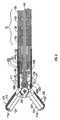
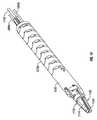
ここで図1〜3を参照し、種々の外科手技で使用するための内視鏡血管封着鉗子10の一実施例を示し、概して、回転し、関節運動し、管状血管および血管組織を保持する、封着するおよび分割するように相互に協働する、ハウジング20、ハンドルアセンブリ30、回転アセンブリ80、関節運動アセンブリ90、トリガーアセンブリ70およびエンドエフェクタアセンブリ100を含む。図面の大部分は、内視鏡外科手技に関連して使用するための双極性封着鉗子10を図示するが、本発明は、電流ループを完了するための遠隔患者パッドを採用する単極外科手技に使用されてもよい。 1-3, there is shown one embodiment of an endoscopic
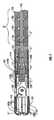
鉗子10は、エンドエフェクタアセンブリ100を機械的に係合するように寸法決定された遠位端16と、ハウジング20を機械的に係合する近位端14とを有する略可撓性シャフト12を含む。一実施形態において、シャフト12は、近位部分と遠位部分の少なくとも2つの部分を有する。シャフトの近位部分は、可撓性の管(例えば、プラスチック)の形状を成してもよく、軸方向強度(例えば、圧縮)および回転強度をもたらすために、編組スチールの管を包含してもよい。また、シャフト12の遠位部分は、可撓性であってもよいが、1つ以上の移動接合部を包含してもよい。ケーシング12´は、可撓性シャフト12の複数の内部移動接合部12aを保護するために採用されてもよい。 The
一実施形態において、シャフトの近位部分は、可撓性かつ非関節運動であり、一方で、シャフト12の遠位部分は、関節運動ケーブルまたはワイヤの移動に応じて関節運動することが可能である。シャフト12がどのように屈曲するかの詳細は、図8および9に関して下記に詳述する。シャフト12の近位端14は、ハウジング20内で受け入れられ、回転アセンブリ80、関節運動型アセンブリ90および駆動アセンブリ150に接続される。付随する図面および記述において、用語「近位」は、従来通りに、ユーザにより近い鉗子10の端部を言い、一方、用語「遠位」は、ユーザからより遠い端部を言う。 In one embodiment, the proximal portion of the shaft is flexible and non-articulated while the distal portion of the
図1で最もよく分かるように、鉗子10は、例えば発電機(図示せず)等の電気外科的エネルギー源に鉗子10を接続する電気外科ケーブル310もまた含む。Boulder,Coloradに所在するTyco Healthcare LPの部門であるValleylabが販売するもの等の発電機は、例えば、ValleylabのLIGASURETM Vessel Sealing GeneratorおよびValleylabのForce TriadTM Generator等の電気外科的エネルギー源として使用されてもよいと考えられる。As best seen in FIG. 1, the
発電機は、絶縁された出力、付属品の独立起動および/またはTyco Healthcare LPの部門であるValleylabが所有する専有技術である所謂「Instant ResponseTM」ソフトウェアを含む、種々の安全およびパフォーマンス特徴を含んでもよい。Instant ResponseTMは、1秒間に200回組織の変化を感知し、適切な電力を維持するために電圧および電流を調整する高度フィードバックシステムである。Instant ResponseTM技術は、血管封着の1つ以上の以下の利点:全ての組織型における一貫した臨床効果、熱拡散および付帯的組織損傷のリスクの減少、「発電機を強める」必要性の低下、を提供すると考えられ、低侵襲環境のために設計されている。The generator includes various safety and performance features, including isolated output, independent activation of accessories and / or so-called “Instant Response™ ” software, proprietary technology owned by Valleylab, a division of Tyco Healthcare LP. But you can. Instant Response™ is an advanced feedback system that senses tissue changes 200 times per second and adjusts voltage and current to maintain proper power. Instant Response™ technology provides one or more of the following benefits of vascular sealing: consistent clinical effects in all tissue types, reduced risk of thermal diffusion and incidental tissue damage, reduced need for “enhance generator” Designed for a minimally invasive environment.
ケーブル310は、図10および11に関して下記で詳述するように、それぞれが各送給経路を介して電気外科的エネルギーを、鉗子10を通ってエンドエフェクタアセンブリ100に伝達するケーブルリード310a、310bおよび310cに内部で分かれる。
ハンドルアセンブリ30は、固定ハンドル50および可動ハンドル40を含む。固定ハンドル50は、ハウジング20と一体的に付随し、ハンドル40は、鉗子10の動作に関して下記で詳述するように、固定ハンドル50に対して可動である。回転アセンブリ80は、ハウジング20と一体的に付随してもよく、シャフト12を介して画定される長手方向軸「A−A」の周りを一方の方向に約180度回転するホイール82を介して回転可能である。1つの企図される回転アセンブリ80は、共有に係る米国特許出願第10/460,926号に開示される。別の企図される回転アセンブリは、共有に係る米国特許出願第11/519,586号に開示される。両出願の全内容は、参照することにより本願明細書に組み込まれる。 The
また、関節運動アセンブリ90は、ハウジング20と一体的に付随してもよく、軸「A−A」に対して矢印「B−B」の方向に、エンドエフェクタアセンブリ100を移動させるために、ホイール92を介して動作可能である。ホイール92は、ハウジング側に配置される等の代替的な構成で提供されてもよい。また、ホイール92は、レバー、トラックボール、ジョイスティック等の関節運動アセンブリ90を関節運動させるために、他の機構に代替されてもよい。関節運動アセンブリ90に関する詳細は、図8および9を参照して下記に詳述する。 The
上記のように、エンドエフェクタアセンブリ100は、シャフト12の遠位端16で取り付けられ、1対の対向顎部材110および120を含む。ハンドルアセンブリ30の可動ハンドル40は、顎部材110および120が互いに対して離間して配置される開位置から、顎部材110および120がそれらの間で組織を保持するように協働する締め付けまたは閉位置に、顎部材110および120を移動させるように、共に機械的に協働する駆動アセンブリ150に最終的に接続される。 As described above, the
ここで本発明の鉗子ハウジング20、シャフト12およびエンドエフェクタアセンブリ100のより詳細な特徴を参照すると、可動ハンドル40は、後述するように、互いに対する顎部材110および120の移動させるように、固定ハンドル50に対する第1の位置から固定ハンドル50に近接した第2の位置に旋回ピン29の周囲で選択的に可動である。可動ハンドルは、それを介して旋回ピン29を受け入れるためのその上端にそれぞれが開口部を有する1対の上フランジを形成するクレビス45を含む。同様に、ピン29は、ハウジング20の両側に配置される。 Referring now to more detailed features of the
また、クレビス45は、ハンドル40の旋回移動が、駆動アセンブリ150に対してフランジを強制し、そして顎部材110および120を閉鎖させることができるように、長手方向軸「A−A」に沿って整列し、駆動アセンブリ150に当接する加力フランジまたは駆動フランジ(図示せず)も含む。可動ハンドル40の下端は、可動ハンドル40に搭載され、固定ハンドル50に対して可動ハンドル40を係止するために、固定ハンドル50内に配置された所定のチャネル51内に乗るT字形遠位端95を含む、フランジ91を含む。 The clevis 45 is also along the longitudinal axis “A-A” so that pivoting movement of the
エンドエフェクタアセンブリ100は、封着目的で、組織を効果的に保持するように協働する対向顎部材110および120を含む。エンドエフェクタアセンブリ100は、片側可動アセンブリとして設計されてもよく、つまり、顎部材120は、シャフト12に対して固定され、顎部材110は、組織を保持するために旋回ピン103の周りで旋回するか、または両側可動アセンブリ、つまり、顎部材110および120の両方が、軸「A−A」に対して移動する。駆動ロッド142または駆動スリーブは、駆動アセンブリ150に操作可能に連結され、互いに対して顎部材110および120を作動させる、つまり旋回させるために、ハンドル50に対するハンドル40の動きを介して選択的に往復可能である。装置の実施形態において、駆動ロッド142は、可撓性であり、例えば、ケーブルであってもよい。
本発明の開示による特定の一実施形態において、ならびに図1〜3に最もよく例証されているように、ナイフチャネル115aおよび115bは、それぞれ上部および/または下部顎部材110および120内で画定されてもよい。ナイフチャネル115aおよび115bは、顎部材110および120が閉位置にある時に、ブレード185が、顎部材110および120間で保持される組織を切断するために、選択的に往復運動され得るように、それぞれ顎部材110および120の中心を通り抜けるように寸法決定される。ブレード185は、顎部材110および120が閉鎖されている時にのみ、ブレード185(またはエンドエフェクタアセンブリ100もしくは駆動アセンブリ150との組み合わせでのブレード185)が、組織を介して前進し得、したがって、組織を介するブレード185の偶発性または早発起動を防ぐことができるように、構成されてもよい。 In one particular embodiment according to the present disclosure, and as best illustrated in FIGS. 1-3,
図2および3に最もよく示されるように、顎部材110は、絶縁顎部ハウジング114および導電性表面112を含む。絶縁体114は、型打ちすることによって、オーバーモールドすることによって、型打ちした導電性封着プレートをオーバーモールドすることによって、および/または金属射出成形シートプレートをオーバーモールドすることによって、導電性封着表面112を確実に係合するように寸法決定される。これらの製造技術の全ては、絶縁顎部ハウジング114で実質的に包囲される導電性表面112を有する顎部材110を生成する。また、顎部材110は、ケーブルリード311を、封着表面112との電気的導通に誘導するように設計される1つ以上のワイヤガイドまたはチャネル(図示せず)を含んでもよい。 As best shown in FIGS. 2 and 3, the
導電性表面112および絶縁顎部ハウジング114は、組立て時に、ナイフブレード185の往復運動のために、それを介して画定される長手方向に配向されたスロット115aを形成する。ナイフチャネル115aは、形成された組織封着に沿って組織を効果的かつ正確に分離させるために、好適な切断面に沿ったナイフブレード185の長手方向の延在を容易にするように、顎部材120内に画定される対応するナイフチャネル115bに協働することが想定される。
顎部材120は、絶縁顎部ハウジング124と、絶縁顎部ハウジング124を確実に係合するように寸法決定される導電性封着表面122等の顎部材110と同様の要素を含む。同様に、導電性表面122および絶縁顎部ハウジング124は、組立て時に、ナイフブレード185の往復運動のために、それを介して画定される長手方向に配向されたチャネル115aを含む。上記のように、顎部材110および120が組織の周囲で閉鎖される場合、ナイフチャネル115aおよび115bは、組織封着に沿って組織を切断するために、遠位方向にナイフ185の長手方向の延在を可能にする。単一のナイフチャネル、例えば、115bが、特定の目的に応じて、2つの顎部材のうちの一方、例えば、顎部材120内に完全に配置されてもよい。顎部材120は、顎部材110に関する上記と同様の方法で組立てられてもよい。
顎部材120は、組織の保持および操作を容易にし、組織の封着および切断時の対向顎部材110と120との間の間隙「G」(図7参照)を画定するために、導電性封着表面122の内部対向面上に配置された一連の停止部材750を含む。効果的かつ確実に組織を封着するのに好適な導電性封着表面112と122との間の間隙「G」は、約0.001から約0.006インチである。停止部材750は、特定の目的に応じて、または所望の結果を達成するために、一方または両方の顎部材110および120上に採用されてもよい。停止部材750は、導電性封着プレート122上に熱的に噴射されてもよく、当技術分野において既知の任意の他の方法で堆積または付着されてもよい。さらに、停止部材750は、特定の顎部構成または所望の手術結果に応じて、導電性顎部表面112および122に沿って任意の構成で配置されてもよい。 The
一実施形態において、顎部材110および120は、シャフト12(またはシャフト12を包囲するスリーブ(図示せず))の端部に係合され、エンドエフェクタアセンブリ100のピボット103の周りを回転するように(回転アセンブリ80を介して)動作可能である。リード311は、第1の電位を顎部材110に運び、第2の電位が、駆動ロッド142(あるいは、上記のスリーブ)を通じて顎部材120に移される。起動すると、2つの電位は、導電性封着プレート112と122との間に保持された組織を通じて電気エネルギーを伝達する。鉗子10を介したリード311の1つの企図される電気的構成に関する詳細は、図10および11を参照して後述する。 In one embodiment,
駆動ロッド142の近位への移動は、顎部材110および120を閉位置に旋回させる。より具体的には、作動すると、ハンドル40は、顎部材110および120を閉鎖するために、概して近位方向で、往復運動する駆動ロッド142をクレビス45に引っ張らせる旋回ピン29の周りで、略弓形に固定ハンドル50に向けて移動する。さらに、ハンドル40の近位回転は、ナイフ185の選択的作動のために、固定フランジ71に、トリガーアセンブリ70を解放させる、つまり「解除させる」。 Proximal movement of the
1つの企図される鉗子10、つまり、駆動アセンブリ150、トリガーアセンブリ70および回転アセンブリ80の内部作業構成部品の動作特徴および相対運動は全て、共有に係る米国特許出願第10/460,926号に記載され、その全内容は、参照することにより本願明細書に組み込まれる。 The operational characteristics and relative motion of the internal working components of one contemplated
上記のように、顎部材110および120は、封着が所望されるまで、組織を操作および保持するために開かれ、閉じられ、回転され、および関節運動されてもよい。これにより、起動および封着に先立って、ユーザが、鉗子10を位置付けるおよび再位置付けることを可能にする。図4に例証されるように、エンドエフェクタアセンブリ100は、回転アセンブリ80の回転ノブ82の回転を介して、長手方向軸「A−A」の周りを回転可能である。また、エンドエフェクタアセンブリ100は、図8および9を参照して下記に詳述するように、矢印「B−B」の方向において一方の方向に関節運動されてもよい。組織が保持されると(約3kg/cm2から約16kg/cm2の必要な圧力範囲内で)、次いで、ユーザは、組織を効果的に封着するために、電気外科的エネルギーを選択的に印加する。封着されると、次いで、ユーザは、組織封着に沿って組織を切断するために、トリガーアセンブリ70を作動することによってナイフ185を選択的に前進させる。As described above,
1つの企図されるトリガーアセンブリ70の動作特徴および相対運動は、上記の共有に係る米国特許出願第10/460,926号に記載される。一実施形態において、例えば、トリガーアセンブリ70の作動により、シャフト12を通じて延在し、ナイフ185に動作可能なように連結されるケーブルは、それによって組織封着に沿って組織を切断するように、遠位で移動する。別の実施形態において、トリガーアセンブリは、トリガーアセンブリの作動を、シャフト12を通じて延在するケーブルの回転運動に変換するギアリングを含む。 The operational characteristics and relative motion of one contemplated
また、1つの企図される駆動アセンブリ150は、米国特許出願第10/460,926号にも開示され、これは、顎部材110および120を開閉させるために、スリーブの選択的な往復運動を伴う。別の企図される実施形態は、駆動アセンブリが、顎部材110および120を開閉させるために駆動ロッドを引く、米国特許出願第11/519,586号に記載される。 One contemplated
図2および3に特に関して、鉗子10は、可撓性シャフト12を形成するために、入れ子のように直列に配列された複数の接合部12aを含む。シャフト12の遠位端16は、エンドエフェクタアセンブリ100を機械的に係合し、シャフト12の近位端14は、ハウジング20を機械的に係合する。可撓性シャフト12の複数の接合部12aのそれぞれは、遠位ナックル12bと、それとともに形成される近位クレビス12cとを含む。各ナックル12bは、隣接接合部12aのクレビス12cを動作可能なように係合する。各接合部12aは、その中に形成される中心管腔12dと、中心管腔12dの両側上に形成される1対の対向管腔12eとを画定する。1対の関節運動ケーブル94aおよび94bは、接合部12のそれぞれの管腔12eを通じて摺動自在に延在する。ケーブル94aおよび94bの動作は、図8および9に関して以下に詳述する。 With particular reference to FIGS. 2 and 3, the
図3に見られるように、エンドエフェクタアセンブリ100は、顎部材110および120を旋回可能に支持するように構成される顎部支持部材222を含む。顎支持部材222は、その近位端の管腔224と、その遠位端の1対の離間されたアーム226aおよび226bとを画定する。管腔224は、可撓性シャフト12の最遠位接合部12aから延在するステム12fを受け入れるように構成および寸法決定される。管腔224は、その中の往復運動のためのナイフブレード185を摺動自在に受け入れるように構成される、その表面中の1対の対向チャネル224a、224bを画定する。 As seen in FIG. 3,
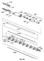
顎部110および120は、支持部材222のアーム226aおよび226bに形成された開口部228と、顎部材110および120に形成された各旋回スロット132a、132bとを通じて延在する顎部旋回ピン234によって、支持部材222上に旋回可能に搭載される。開位置と閉位置との間で顎部110および120を移動させるために、カムピン138を有する軸方向または長手方向に可動の中心ロッド136は、その中心ロッド136の遠位端136aで顎部支持部222内に搭載される。駆動ロッド142を介した中心ロッド136の軸方向または長手方向の移動により、顎部110および120が開位置と閉位置との間にカム作用をもたらすことができるように、カムピン138は、各顎部材110および120に形成された傾斜カムスロット132aおよび132bに乗り、それらを係合する。 The
また、エンドエフェクタアセンブリ100は、中心ロッド136の近位端136bに回転自在に接続された遠位端140aを有する係止ロッド140も含む。係止ロッド140は、駆動ロッド142の遠位端に固定して接続された近位端140b、ならびに非円形断面形状を有する、遠位端140aと近位端140bとの間に配置された本体部分140cを含む。 The
エンドエフェクタアセンブリ100は、その中の係止ロッド140の本体部分140cを摺動自在に受け入れるように構成および適合された、それを介して画定される管腔144aを有するカムハブ144を含むカムアセンブリ141をさらに含む。カムハブ144は、下記に詳述するような回転目的で、2つの構成部品半分の有益な係合を可能にするように、係止ロッド140の本体部分140cの外側周辺構成に協働する、その中に画定される噛合機械インターフェースを含む。また、カムハブ144は、下記にまた詳述する目的で、ナイフ185の戻り止め187を機械的に係合するように構成されるその外表面に画定されるらせん状またはスパイラル溝144bも含む。カムハブ144は、支持部材222の管腔124内で回転自在に配置されるように構成される。代替的な実施形態において、カムハブ144は、回転運動を直線運動に変換させるために、他の機構(例えば、主ネジ、1つ以上の歯車等)に代替されてもよい。 The
動作中、駆動ロッド142は、その軸方向変位が、開位置と閉位置との間で顎部材110および120を作動させることと、その回転運動が、組織を介してナイフ185を前進させることの、2つの異なる別々の機能を提供するように構成される。より具体的には、駆動ロッド142の軸方向変位は、係止ロッド140に軸方向変位を与え、同様に、中心ロッド136に軸方向変位を与える。しかしながら、カムハブ144は、軸方向かつ摺動自在に係止ロッド140上に支持されるため、それに軸方向変位は与えられない。図5および6に最もよく示されるように、矢印「F」の方向の駆動ロッド142の近位への平行移動は、カムスロット132aおよび132b内に近接するカムピン138に、必要な閉鎖圧および必要な間隙「G」範囲内で組織周りに顎部材110および120を閉鎖させる。代替的な実施形態において(図示せず)、駆動ロッド142によって作動された機能は、ナイフ185を前進させる軸方向変位ならびに顎部材110および120を開閉させる回転運動に逆にされてもよい。次いで、導電性封着プレート112および122は、顎部材110および120間に保持された組織を介して電気エネルギーを伝達するために励起される。 In operation, the
1つ以上の安全特徴は、エネルギーを供給する前に、組織が顎部材110と120との間で効果的に保持されることを確実にするように鉗子10内で機械的にまたは発電機(図示せず)で電気的に用いられてもよい。 One or more safety features can be mechanically or within the
適切な組織封着が形成されると、組織は、組織封着に沿って切断され得る。再び、1つ以上の安全特徴は、組織を切断する前に、適切な封着が形成されたことを確実にするように用いられてもよい。例えば、発電機は、適切かつ効果的な封着が形成された場合を除いて、ナイフ185の作動を電気的に阻止するかまたは電気機械的に阻止する、安全ロックアウトを含んでもよい。上記のように、血管または組織封着が、単に組織を凝固するだけでないこと、ならびに組織を効果的封着するために、圧力、エネルギーおよび間隙「G」の正確な制御を必要とすることに留意することもまた重要である。 Once an appropriate tissue seal is formed, the tissue can be cut along the tissue seal. Again, one or more safety features may be used to ensure that a proper seal has been formed prior to cutting the tissue. For example, the generator may include a safety lockout that electrically or electromechanically prevents the operation of the
本発明の開示は、トリガーアセンブリ70を介して起動された時に、組織を効果的かつ確実に2つの封着された半分に分割するような正確な方法で、理想的な組織平面に沿って組織を段階的かつ選択的に分割させるナイフ185を包含する。ナイフ185は、カニューレまたはトロカールポートを介して切断器具を交換することなく、封着直後にユーザが組織を早急に分離することを可能にする。理解され得るように、組織の正確な封着および分割は、同じ鉗子10で達成される。 The present disclosure discloses tissue along an ideal tissue plane in an accurate manner that, when activated via
また、ナイフブレード185は、組織封着に沿った組織の分離を容易にするために、同じまたは代替的な電気外科的エネルギー源に連結されてもよいことが想定される。さらに、ナイフブレード先端185aの角度は、特定の目的に応じて、より侵略的なまたはあまり侵略的でない切断角度を提供するように寸法決定され得ることが想定される。例えば、ナイフブレード185は、切断と関連する「組織束」を減少させる角度で位置付けされてもよい。さらに、ナイフブレード185は、特定の目的に応じて、または特定の結果を達成するために、鋸歯状、刻み目、穿孔、中空、凹状、凸状等の異なるブレード形状を有して設計されてもよい。ナイフ185は、進行性か一方向の方法(つまり、遠位方向)で概して切断することが想定される。上記のように、駆動ロッドは、顎部材110および120を開閉させること、ならびに組織を切断するために、ナイフ185を前進させることの2つの機能を行う(図7参照)。組織を切断するために、駆動ロッド142の回転は、係止ロッド140に回転を与え、同様に、カムハブ144に回転を与える。しかしながら、係止ロッド140は、中心ロッド136に回転自在に接続されるために、それに回転は与えられない。 It is also envisioned that the
エンドエフェクタアセンブリ100は、支持部材222の各チャネル224aおよび224b内で摺動自在に支持されるナイフ185に動作可能に連結される。より具体的には、ナイフ185は、その遠位端の鋭利なまたは鋸歯状エッジ185aと、そこから近位に延在する1対のガイドフランジ186aおよび186bとを含む。フランジ186aの近位端は、カムハブ144に画定されるスパイラルまたはらせん状溝144bを係合し、それに乗るように構成される戻り止めまたは突出187を含む。
動作中、カムハブ144が矢印「C」の方向に回転するにつれて、近位端187は、カムハブ144の溝144b内に乗り、それに対して軸方向「A1」に移動する。一方向のカムハブ144の回転は、それぞれ顎部材110および120内のナイフチャネル115aおよび115bを介して、ブレード185を遠位に強制し、その間に配置された組織を切断する。反対方向の回転は、近位端187を近位に強制し、最近接位置にブレード185を待避させる。バネが、ナイフ185を最近位配向に付勢するために、カムハブ144と動作可能なように付随され得る。 In operation, as the
上記のように、エンドエフェクタアセンブリ100はまた選択可能に関節運動されてもよい。より具体的には、関節運動アセンブリ90を介してエンドエフェクタアセンブリ100を関節運動させるために、軸方向に配列された状態におけるエンドエフェクタアセンブリ100を用いて図8に示すように、ホイール92は、対応する第1の方向にエンドエフェクタアセンブリ100を移動させるために、第1の方向に回転し、ならびに反対方向にエンドエフェクタアセンブリ100を移動させるために、反対の方向に回転するように構成される。種々の滑車アセンブリおよびギアリングアセンブリがこの目的を達成するために用いられ得る。 As described above,
例えば、一実施形態において、ハンドルアセンブリは、ハウジングからの動作可能な少なくとも1つの関節運動ケーブルを含んでもよい。各関節運動ケーブルは、エンドエフェクタと動作可能なように接続可能な遠位端と、例えば、ハウジング上に支持されたスライダ、ダイヤル、レバー等の制御要素のうちの少なくとも1つに動作可能なように接続可能な近位端とを含む。動作中、制御要素の移動は、少なくとも1つの関節運動ケーブルの移動をもたらし、第1の方向での少なくとも1つの関節運動ケーブルの移動は、エンドエフェクタの関節運動を与え、第2の方向での少なくとも1つの関節運動ケーブルの移動は、第2の方向でのエンドエフェクタの関節運動を与える。 For example, in one embodiment, the handle assembly may include at least one articulation cable operable from the housing. Each articulation cable is operable to move to at least one of a distal end operably connectable with an end effector and a control element such as a slider, dial, lever, etc. supported on the housing. A proximal end connectable to. In operation, movement of the control element results in movement of at least one articulation cable, movement of at least one articulation cable in the first direction provides articulation of the end effector, and movement in the second direction. Movement of the at least one articulation cable provides articulation of the end effector in the second direction.
第1の方向での制御要素の移動が、第1の方向での第1の関節運動ケーブルの移動および第2の方向での第2の関節運動ケーブルの移動をもたらし、第2の方向での制御要素の移動が、第2の方向での第1の関節運動ケーブルの移動および第1の方向での第2の関節運動ケーブルの移動をもたらすように、1対の関節運動ケーブルは、制御要素に動作可能なように接続された近位端をそれぞれ有して提供されてもよい。 Movement of the control element in the first direction results in movement of the first articulation cable in the first direction and movement of the second articulation cable in the second direction, The pair of articulation cables is connected to the control element such that movement of the control element results in movement of the first articulation cable in the second direction and movement of the second articulation cable in the first direction. Each having a proximal end operatively connected thereto.
より具体的に、ならびに図8および9を参照して、第1の関節運動94bケーブル(つまり、図8および9に示すような下部関節運動ケーブル)が、図9の矢印「D」で示すように、ホイール92を介して近位方向に引かれた場合、最遠位接合部12aに固定された関節運動ケーブル94bの遠位端は、ナックル112bおよびクレビス112c間のインターフェースの周りを回転し、それによって、それらの間に画定される間隙をその側面に沿って収縮させる。このようにして、エンドエフェクタアセンブリ100は、矢印「B」の方向の下向きの方向に、つまり、長手方向軸「A−A」に対して横断方向に関節運動される。エンドエフェクタアセンブリ100を非関節運動状態に戻すために、またはエンドエフェクタアセンブリ100を反対方向に関節運動させるために、関節運動ケーブル94a(つまり、図8および9に示すような上部関節運動ケーブル)は、反対方向へのホイール92の回転によって、近位方向に引かれてもよい。 More specifically, and with reference to FIGS. 8 and 9, the
種々のハンドルおよび/またはハンドルアセンブリは、その種々の構成部品の動作および移動を生じさせるために、つまり、ケーブル142および/または関節運動ケーブル94a、94bを駆動させるために、エンドエフェクタアセンブリ100と動作可能なように接続あるいはその他付随してもよい。エンドエフェクタ1100とともに使用するための例示的なハンドルおよび/またはハンドルアセンブリは、2006年10月5日出願の米国仮特許出願第60/849,562号「PROGRAMMABLE HANDLE ASSEMBLY FOR SURGICAL DEVICES」および2006年10月5日出願の米国仮特許出願第60/849,560号「HANDLE ASSEMBLY FOR ARTICULATED ENDOSCOPIC INSTRUMENTS」に開示され、それらのどちらの開示も参照することによりそれら全体が本願明細書に組み込まれる。 The various handles and / or handle assemblies operate with the
図10および11は、導線310a、310b、310cおよび311が、電気外科ケーブル310によってハウジング20を通る、想定される一実施形態を示す。より具体的には、電気外科ケーブル310は、固定ハンドル50を通って、ハウジング20の底部に入る。リード310cは、直接ケーブル310から回転アセンブリ80に延在し、第2の電位を顎部材120へ伝導するために、駆動ロッド142に(ヒューズ付きクリップまたはバネクリップ等を介し)接続する。リード310aおよび310bは、ケーブル310から延在し、ハンドスイッチまたはジョイスティック様トグルスイッチ400に接続する。 FIGS. 10 and 11 show one possible embodiment where the
一実施形態において、スイッチ400は、(組み立てられると)ハウジング20の外形に適合し得る人間工学的に寸法決定したトグルプレート405を含んでもよい。スイッチ400は、さまざまな異なる配向、つまり多配向の起動においてユーザが鉗子10を選択的に起動することができることが想定される。理解され得るように、これにより、起動が単純化される。1対の突起404aおよび404bは遠位へ延在し、ハウジング20内に配置された対応する1対の機械的インターフェース21aおよび21bと嵌合する。トグルプレート405は、電気的インターフェース401に順に接続するスイッチボタン402と機械的に嵌合する。導線310aおよび310bは、電気的インターフェース401に電気的に接続する。トグルプレート405が押下げられた時に、トリガリード311は、第1の電位を顎部材110に運ぶ。より具体的には、リード311は、最終的に顎部材110に接続するように、インターフェース401から回転アセンブリ80を通り、シャフト12の一部に沿って延在する。リード310cは、顎部材120に最終的に接続する駆動シャフト142に直接接続するか、または顎部材120に直接延在し、第2の電位を運ぶように構成され得る。 In one embodiment, the
安全スイッチまたは回路(図示せず)は、顎部材110および120が閉鎖されない限り、および/または顎部材110および120がそれらの間に保持される組織を有さない限り、スイッチが発射できないようにするために用いられ得ることが想定される。後者の場合、センサ(図示せず)は、組織がそれらの間に保持されるかどうかを決定するために用いられてもよい。さらに、手術前、同時手術(つまり、手術中)および/または手術後条件を決定する他のセンサ機構が用いられてもよい。また、センサ機構は、1つ以上の手術前、手術中または手術後条件に基づいて電気外科的エネルギーを調節するために、電気外科的発電機に連結された閉ループフィードバックシステムとともに利用されてもよい。米国特許出願第10/427,832号は、そのような一フィードバックシステムに関して記載し、参照することによりその内容全体が本願明細書に組み込まれる。 A safety switch or circuit (not shown) prevents the switch from firing unless the
上記のように、少なくとも1つの顎部材、例えば、120は、2つの対向顎部材110および120の互いに対する移動を制限する停止部材750を含んでもよい。一実施形態において、停止部材750は、特定の材料特性(例えば、圧縮強度、熱膨張等)に従って所定の距離を封着表面122から延び、封着時に一貫した正確な間隙距離「G」をもたらす。封着時の対向封着表面112と122との間の間隙距離は、約0.001インチから約0.006インチ、より好ましくは約0.002から約0.003インチの範囲であることが想定される。一実施形態において、非導電性停止部材750は、顎部材110および120上に成形され(例えば、オーバーモールド、射出成形等)、顎部材110および120上に型打ちされ、または顎部材110および120上に堆積される(例えば、沈着)。例えば、一技術は、停止部材750を形成するために、顎部材110および120の表面上にセラミック材料を熱的に噴霧することを含む。導電性表面112と122との間の間隙距離を制御するための停止部材750を生成するために、広範囲の耐熱および絶縁材料を種々の表面上に堆積させることを伴う幾つかの熱噴霧技術が企図される。 As described above, at least one jaw member, eg, 120, may include a
図15〜21は、血管封着手技とともに使用する電気外科的関節運動鉗子1000の代替的な実施形態を示す。鉗子1000の多くの上記特徴は、鉗子10と同様であり、一貫性の目的のために、これらの特徴は、より短く後述される鉗子1000の以下の記述に組み込まれる。 15-21 illustrate an alternative embodiment of an
鉗子1000の動作は、鉗子10と同様であり、固定ハンドル1050に対して可動である可動ハンドル1040を含む。可動ハンドル1040は、後述するように、互いに対する顎部材1110および1120の移動させるように、固定ハンドル1050に対する第1の位置から固定ハンドル1050により近接する第2の位置へ1対のピボット1047および1057(図14C参照)の周りを選択的に可動である。同様に、各ピボット1047および1057は、ハウジング半分1020aおよび1020bのそれぞれに搭載される。 The operation of the
ハンドル1040は、ハンドル1040を移動すると、後述するように、駆動アセンブリ1700に対応する移動をもたらす、1対の連結部1042および1045に動作可能に連結される。ハンドル1040および1050、ピボット1047および1057ならびに連結部1042および1045の配列は、従来のハンドルアセンブリよりも明白な機械的利点をもたらし、ユーザが、顎部材1110および1120を作動させるレバーのような機械的利点を得ることを可能にする。これにより、組織封着を生じさせるために、顎部材1110および1120を閉鎖するのに必要な機械力の全体的な量が減少する。 The
図1〜14に関して説明した実施形態によく類似して、可動ハンドル1040の下端は、固定ハンドル1050内に配置された所定のチャネル1051内に乗るT字形遠位端1044´を含むフランジ1044を含む。T字形遠位端1044´は、下記に詳述するように、固定ハンドル1050に対して可動ハンドル1040を係止する。 Similar to the embodiment described with respect to FIGS. 1-14, the lower end of the
エンドエフェクタアセンブリ1100は、封着目的で組織を効果的に保持するように協働する対向顎部材1110および1120を含む。エンドエフェクタアセンブリ1100は、片側可動アセンブリとして設計され、つまり、顎部材1120は、シャフト1012に対して固定され、顎部材1110は、旋回ピン1134の周りを旋回して、組織を保持する。より具体的には、片側可動エンドエフェクタアセンブリ1100は、シャフト1012に対して固定して搭載された1つの静止または固定顎部材1120と、静止顎部材1120に取り付けられた旋回ピン1134周りに搭載された旋回顎部材1110とを含む。往復スリーブ1230は、シャフト1012内に摺動自在に配置され、駆動アセンブリ1700によって遠隔で動作可能である。旋回顎部材1110は、顎部材1110から、往復スリーブ1230(図14A)内に配置された開口部1232を通って延在する戻り止めまたは突出1113を含む。旋回顎部材1110は、開口部1232の遠位端が、旋回顎部材1110上の戻り止め1113に対して当接するように、シャフト1012内においてスリーブ1230を軸方向に摺動させることによって作動される(図16A〜17B参照)。スリーブ1230を引くことにより、それらの間に保持された組織の周りに顎部材1110および1120を近接して閉鎖させ、スリーブ1230を遠位に押すことにより、保持する目的で、互いに対して顎部材1110および1120を開かせる。
片側可動エンドエフェクタアセンブリ1100は、電気エネルギーが、スリーブ1230との突出1113の接触点でスリーブ1230を介して経路決定されるか、あるいは顎部材1110が閉鎖する時に、移動する顎部材1110の背部と接触する「ブラシ」またはレバー(図示せず)を使用して経路決定され得るように、構成されてもよい。この場合、電気エネルギーは、顎部材1110または1120のうちの一方まで突出1113を介して経路決定されるであろう。あるいは、電気ケーブルリード1455は、顎部材のうちの一方、例えば、顎部材1120を励起するように経路決定され得、他方の電位は、リード1450(図16C参照)との電気接触を経由して、スリーブ1230を通じて伝導され、スリーブ1230が撤退すると、電気的導通を設立する旋回顎部材1110に移動する。 The one-side movable
顎部材1110および1120は、それぞれ顎部絶縁体114および124ならびに導電性封着表面112および122(図13参照)等の、上記のような顎部材110および120と同様の要素を含む。また、顎部材1120は、組織の保持および操作を容易にするため、ならびに組織の封着および/または切断時に、対向顎部材1110と1120との間の間隙「G」(図17A参照)を画定するために、導電性封着表面1122の内部対向面上に配置された一連の停止部材750(図16B参照)も含む。一連の停止部材750は、特定の目的に応じて、または所望の結果を達成するために、一方または両方の顎部材1110および1120上にさまざまな構造で用いられてもよいことが想定される。
関節運動アセンブリ1090は、ハウジング1020に動作可能なように連結される。関節運動ホイール1090aおよび1090bは、ハウジング1020の側面に配置される等の代替的な配置で提供されてもよい。ホイール1090aおよび1090bは、レバー、トラックボール、ジョイスティック等の関節運動アセンブリ1090を作動させるために、他の機構で代替されてもよいことが想定される。より具体的には、図18A〜18Cの比較に見られるように、1つのホイール1090a、1090bの選択的な回転後、エンドエフェクタアセンブリ1100は、軸方向に配列された状態(図18B)から、関節運動状態(図18C)に関節運動されてもよい。関節運動アセンブリ1090を介してエンドエフェクタアセンブリ1100を関節運動させるために、ホイール1090aおよび1090bは、対応する第1の方向にエンドエフェクタアセンブリ1100を移動させるために、第1の方向に回転し、反対方向にエンドエフェクタアセンブリ1100を移動させるために、反対方向に回転するように構成される。この目的を達成するために、種々の滑車アセンブリおよびギアリングアセンブリが用いられ得る。
例えば、および上記の関節運動構成と同様に、2つの関節運動ケーブル1094aおよび1094bは、シャフト1012の可撓性部分1012bを関節運動させるために利用され得る。図16Cに最もよく示されるように、各関節運動ケーブル1094aおよび1094bは、シャフト1012の遠位端に配置されたエンドエフェクタ連結アセンブリ1016と動作可能なように接続する、遠位端1094a´および1094b´を含む。連結アセンブリ1016は、往復運動のための駆動ロッド1142を係合し、種々の電気接続を顎部材1110および1120へと誘導するように設計される、一連の機械的に相互協働する要素を受け入れるように設計されたその中に画定される空洞1225を含む。駆動ロッド1142は、鉗子1000が関節運動される時に、駆動ロッド1142を所与の方向に屈曲させることを可能にするために、好ましくは、可撓性の低摩擦材料から作られる。低摩擦材料は、関節運動時の座屈を減少させる。 For example, and similar to the articulation configuration described above, two
連結アセンブリは、ピン1231を介して、駆動ロッド1142の遠位端1142´を駆動スリーブ1230に係合および固定する1対のブッシング1220および1240を含む。ブッシング1240は、端部1142´の近位にある駆動ロッド1142上で摺動自在に係合し、ブッシング1220は、ブッシング1240を係合し、それらの間で端部1142´を固定するように構成される。ピン1231は、固定されたブッシング1240および1220ならびに駆動ロッド1142を、駆動スリーブ1230に連結させる。駆動スリーブ1230(および固定された駆動ロッド1142)は、下記に詳述するような駆動アセンブリ1700が作動されると、その中における平行移動を摺動させるための空洞1225内で受け入れられる。 The coupling assembly includes a pair of
また、連結アセンブリ1016は、それらの間の任意の回転運動を制限するために、顎部材1120に対して固定された関係にある連結アセンブリ1016(および駆動ロッド1142)を係止するように、顎部材1120の近位端1117を係合するように構成された係止要素1210も含む。また、連結アセンブリ1016は、組み立てられると(図14A参照)、下部顎部材1120を支持する遠位フランジ1017も含む。図16Cに最もよく示されるように、連結アセンブリ1016は、リード1450と駆動スリーブ1230との間の電気接続も支持する。さらに、連結アセンブリ1016は、顎部材1110に接続するために、それを介して導線1455(想像線で図示)もまた誘導する。 The
動作中、関節運動ホイール1090aおよび1090bのうちの一方の移動は、反対方向における、関節運動ケーブル1094aおよび1094bの移動をもたらす。より具体的に、ならびに図14C、18A、20Aおよび20Bに最もよく示されるように、関節運動アセンブリ1090は、ハウジング1020aおよび1020bの両側上に配置された対応する歯車部材1096aおよび1096bに嵌合連結する、ホイール1090aおよび1090bを含む(図20A参照)。6角軸1095は、歯車部材1096aおよび1096bの両方を通して搭載され、両端で、ホイール1090aおよび1090bで覆われる。軸1095は、機械的に嵌合する表面(摩擦嵌め、形状嵌め等)によって、あるいは当分野において通常の他の方法で、歯車部材1096aおよび1096b内に固定される。ホイール1090aおよび1090bの歯車のような構成は、所与の方向における関節運動部材1090の増分的な止まりを可能にし、各ホイールの1対のセットバネ1091は、所与の任意の方向におけるホイールの反跳を防ぐ。言い換えれば、セットバネ1091は、歯車、例えば、歯車1096bと互いに噛み合うように構成され、時計回りまたは反時計回り方向への増分的な前進を可能にする。歯車、例えば、歯車1096bに対するセットバネ1091の傾向力は、任意の所望の関節運動位置に可撓性シャフト1012bを維持するのに十分である。 In operation, movement of one of
軸1095は、ケーブル1094aおよび1094bと動作的に関連する、ハウジング1020内の滑車アセンブリ1600を支持する。より具体的には、滑車アセンブリ1600は、軸1095上での回転のために搭載された2つの滑車1610aおよび1610bを含む。各滑車1610aおよび1610bは、その往復運動を容易にするために、対応する滑車1610aおよび1610b上のそれぞれのケーブル1094aおよび1094bを誘導する、対応するガイドスリーブ1620aおよび1620bを含む。図18Aに最もよく示されるように、ケーブル1094aは、一方の方向における回転のために滑車1620bを係合するように設計され、一方で、ケーブル1094bは、反対方向における回転のために滑車1620aを係合するように設計される。理解され得るように、これにより、可撓性シャフト1012bを関節運動するために、滑車1610aおよび1610bをプッシュプル式方法で動作させることが可能となる。言い換えれば、一方のケーブル1094aがP1の方向に引かれるにつれて、他方のケーブル1094bはP2の方向に押され(または緩められる)、可撓性シャフト1012bを、所与の方向(図18C参照)に関節運動させることを可能にする。また、ガイドスリーブ1620aおよび1620bは、可撓性シャフト1012bの一貫した関節運動を容易にし、増強させるために、各ケーブル1094bおよび1094aを事前緊張する。
図14Bに最もよく示されるように、駆動アセンブリ1700は、最終的な組み立てに先立って、互いに対して顎部材1110および1120の開きを製造業者が微調整することを可能にする、駆動ロッド1142と動作可能に付随された微調整アセンブリ1061もまた含む。より具体的には、駆動ロッド1142は、後述するような駆動アセンブリ1700に接続された駆動ロッド1142aに接続するアダプタ1063に接続する。アダプタ1063は、駆動アセンブリ1700に対する駆動ロッド1142の長さを製造業者が微調整することを可能にし、それによって、顎部材1110および1120の相対分離距離を正確かつ微細に制御することを可能にするために、調整ノブ1067を螺合可能に係合するようにその遠位端で螺合される。 As best shown in FIG. 14B, the
図14C、15A、15B、19Aおよび19Bに最もよく示されるように、駆動アセンブリ1700の作動は、組織を保持および封着するために、ユーザが顎部材1110および1120を選択的に開閉することを可能にする。より具体的には、駆動アセンブリ1700は、駆動ロッド1142およびそれに対する連結駆動ロッド1142aを付勢する圧縮バネ1740を動作可能に搭載するフレームブロック1800を含む。連結駆動ロッド1142aは、アダプタ1720によって、フレームブロック1800の遠位端に順に連結される、駆動ブロック1710に搭載される。組み立てられたとき、フレームブロック1800は、ハンドル1040が作動されると、フレームブロック1800をハウジング1020内で移動することを可能にする、ハウジング半分1020aおよび1020b(図14C参照)内に画定された対向レール1021の間に配置される。バネ1740は、スペーサ1730(アダプタブロック1720に隣接して配置)と、フレームブロック1800の近位端1810との間に搭載される。駆動ピン1750は、駆動ブロック1710の反対端に搭載され、駆動ロッド1142の移動を可能にする圧縮バネ1740を支持する。 As best shown in FIGS. 14C, 15A, 15B, 19A and 19B, actuation of the
上記のように、ハンドル1040は、ハンドル1050に対するハンドル1040の移動が、顎部材1110および1120を開閉させるために、駆動ロッド1142を平行移動できるように、駆動アセンブリ1700に動作可能に搭載される。より具体的には、ハンドル1040は、ピン1047を介してその上端または遠位端で連結金具1045に搭載され、連結金具1045は、ピン1047を介してフレームブロック1800に搭載される。また、ハンドル1040は、旋回点1041で連結金具1042に搭載され、次に、連結金具1042は、ピボット1057でハンドル1050に搭載され、4棒機械的アセンブリを完成させる。図19Aおよび19Bの比較に最もよく示されるように、ハンドル1050に向かったハンドル1040の移動は、フレームブロック1800を近位方向に強制するように、2つの連結金具1042および1045を回転させ、顎部材1110および1120を閉鎖させるために、駆動ロッド1142aを近位に引く(これは、駆動ロッド1142を近位に引く)。同時に、フランジ1044は、T字形端部1044´が、ハンドル1050に対して適所にハンドル1040を係止できるように、ハンドル1040の底部に動作可能に連結され、ハンドル1050内に画定されるガイドチャネル1051内を往復運動する。フランジ1044およびチャネル1051は、鉗子10に関して上述したような同様の方法で動作する。 As described above, the
バネ1740は、駆動ピン1750上に摺動自在に搭載された、バネに配置された2つの対向する圧縮ディスク1740aおよび1740bを含む。ハンドル1050に向かってハンドル1040が移動すると、バネディスク1740aは、駆動ピン1750上で圧縮し、そして駆動ロッド1142を近位に引くように、アダプタ1720の移動から力を受ける。上記のように、駆動ロッド1142の近位への移動により、駆動スリーブ1230は、顎部材1110のフランジ1113を係合し、顎部材1120に対して顎部材1110を閉鎖させる。その後、フランジ1044は、ハンドル1050に画定される止め部1052を係合するT字形端部1044´によって、ハンドル1050に対してハンドル1040を係止する。ハンドル1040を再び握ると、フランジ1044上のT字形端部1044´は、ハンドル1050から離れて移動するように、ハンドル1040を解放するようにチャネル1051から外へ再び方向付けされる。バネ1740は、開く配向にハンドル1040を付勢する。
上記のように、顎部材1120は、組織の封着および切断時に、組織の保持および操作を容易にし、対向顎部材1110と1120との間の間隙「G」(図17A参照)を画定するために、導電性封着表面1122の内部対向面上に配置された一連の停止部材750を含んでもよい。効果的かつ確実に組織を封着するのに好適な導電性封着表面1112と1122との間の間隙「G」は、約0.001から約0.006インチである。停止部材750は、特定の顎部構成または所望の手術結果に応じて、導電性顎部表面1112および1122に沿って任意の構成で配置されてもよい。 As described above,
また、エンドエフェクタアセンブリ1100は、図18Aに関連して示すような両方向(矢印「B−B」参照)で関節運動されてもよい。組織が保持されると(約3kg/cm2から約16kg/cm2の所要圧力範囲内で)、次いで、ユーザは、組織を効果的に封着するために、電気外科的エネルギーを選択的に印加する。封着されると、次いで、ユーザは、組織封着に沿って組織を切断するために、トリガーアセンブリ(図示せず)を作動させることによって、ナイフ(図示せず)を選択的に前進させることができる。1つの想定されるナイフおよびトリガーアセンブリの動作特徴および相対運動は、上記に記述され、またその全体が本願明細書に組み込まれる米国特許出願第10/460,926号を参照しても記述される。
上記の図2および3と同様に、鉗子1000は、可撓性シャフト1012bを形成するために、入れ子のように直列に配列された複数の接合部1312を含む。遠位端または連結アセンブリ1016は、エンドエフェクタアセンブリ1100を機械的に係合し、シャフト1012の近位端1014は、ハウジング1020を機械的に係合する。可撓性シャフト1012bの複数の接合部1312のそれぞれは、遠位ナックル1312aおよびそれとともに形成された近位クレビス1312bを含む。各ナックル1312aは、隣接接合部1312aのクレビス1312bを動作可能に係合する。各接合部1312は、その中に画定される中心管腔1317と、中心管腔1317の両側面に形成された1対の対向管腔1315aおよび1315bとを有する。関節運動ケーブル1094aおよび1094bは、接合部1312の各管腔1315aおよび1315bを通って摺動自在に延在する。ケーブル1094aおよび1094bの動作は上に説明した。関節運動ケーブル1094aおよび1094bは、好ましくは、可撓性の低摩擦材料から作られる。 Similar to FIGS. 2 and 3 above, the
ハウジング1020の外形に適合し得るスイッチ2000が(組み立てられると)含まれる。スイッチ2000は、さまざまな異なる配向、つまり多配向の起動においてユーザが鉗子1000を選択的に起動することができることが想定される。理解され得るように、これにより、起動が単純化される。押しボタン2010は、遠位に延び、電気的インターフェースまたはプリント基板(図示せず)に順に接続するトグルプレート2015(図15B参照)を係合する。ケーブル2020(図19参照)内部に配置される導線2025aおよび2025bは、電気的インターフェースまたはプリント基板に電気的に接続する。押しボタン2010が押下された時に、リード2025aおよび2025bは、電位を顎部材1110および1120に運ぶ。 A
安全スイッチまたは回路(図示せず)が、顎部材1110および1120が閉鎖されない限り、および/または顎部材1110および1120がそれらの間に保持される組織を有さない限り、スイッチが発射できないようにするために用いられてもよいことが想定される。後者の場合、センサ(図示せず)は、組織がそれらの間に保持されるかどうかを決定するために用いられてもよい。さらに、手術前、同時手術(つまり、手術中)および/または手術後条件を決定する他のセンサ機構が用いられてもよい。また、センサ機構は、1つ以上の手術前、同時手術または手術後条件に基づいて電気外科的エネルギーを調節するために、電気外科的発電機に連結された閉ループフィードバックシステムとともに利用されてもよい。米国特許出願第10/427,832号は、そのような一フィードバックシステムに関して記述し、その全内容は、参照することにより本願明細書に組み込まれる。 A safety switch or circuit (not shown) prevents the switch from firing unless the
種々のハンドルおよび/またはハンドルアセンブリは、その種々の構成部品、つまり、駆動ロッド1142および/または関節運動ケーブル1094a、1094bの動作および移動をもたらすために、エンドエフェクタアセンブリ1100と動作可能なように接続または付随されてもよい。エンドエフェクタ1100とともに使用される例示的なハンドルおよび/またはハンドルアセンブリは、2006年10月5日出願の米国仮特許出願第60/849,562号「PROGRAMMABLE HANDLE ASSEMBLY FOR SURGICAL DEVICES」、および2006年10月5日出願の米国仮特許出願第60/849,560号「HANDLE ASSEMBLY FOR ARTICULATED ENDOSCOPIC INSTRUMENTS」に開示され、それぞれの全開示は、参照することにより本願明細書に組み込まれる。 The various handles and / or handle assemblies are operably connected to the
上記種々の図面から、およびそれらを参照して、同業者は、本発明の範囲から逸脱することなく、本発明に特定の変更を行うことができることを理解されたい。例えば、鉗子10(および/または鉗子10に関連して使用される電気外科的発電機)は、顎部材110と120との間に保持された特別にサイズ決定された組織を効果的に封着するために、適切な量の電気外科的エネルギーを自動的に選択するセンサまたはフィードバック機構(図示せず)を含んでもよいと考えられる。また、センサまたはフィードバック機構は、封着時に組織全体にわたるインピーダンスを測定し、顎部材110と120との間に生成された効果的な封着であるという指標(視覚および/または可聴)を提供してもよい。そのようなセンサシステムの実施例は、2003年5月1日に出願された共有に係る米国特許出願第10/427,832号「METHOD AND SYSTEM FOR CONTROLLING OUTPUT OF RF MEDICAL GENERATOR」に記載され、その全内容は、参照することにより本願明細書に組み込まれる。 From the various figures above and with reference thereto, it should be understood that those skilled in the art can make certain changes to the present invention without departing from the scope of the present invention. For example, forceps 10 (and / or an electrosurgical generator used in conjunction with forceps 10) effectively seals specially sized tissue held between
理解され得るように、スイッチ400、2000を鉗子10,1000上に位置付けることには多くの利点がある。例えば、スイッチ400、2000は、手術室における電気ケーブルの量を減少させ、「見通しの良い」起動に起因して、外科手技時に間違った器具を起動させる可能性を除去する。さらに、スイッチ400、2000は、ナイフ185の起動時に使用停止されてもよいことが想定される。トリガが作動された時に、スイッチ400、2000を使用停止することにより、切断工程時に、鉗子10、1000を無意識に起動させることを無くす。また、スイッチ400、2000は、鉗子10,1000の別の部分、例えば、ハンドル40、1040、回転アセンブリ80、ハウジング20等上に配置されてもよいことも想定される。 As can be appreciated, positioning the
別の想定される安全機構は、恐らく、一方の顎部材、例えば顎部材1120を励起するために、ケーブルリードのうちの一方を経路決定し、他方の電位は、例えば、駆動ロッド1142を包囲する駆動スリーブ1230等の駆動スリーブを通じて伝導し、駆動スリーブの撤退後のみ電気的導通を確立するように、他方の顎部材1110に移されてもよい。この特定の想定される実施形態は、少なくとも1つの付加的な安全特徴を提供すること、つまり、顎部材1110および1120が閉鎖されたときにのみ、顎部材1110および1120への電気的導通がなされることが想定される。また、駆動ロッド1142が、第2の電位に励起され、同様のタイプの安全機構を含んでもよい。 Another possible safety mechanism would probably route one of the cable leads to excite one jaw member, eg,
想定される一実施形態において、ナイフ185は、鉗子10、1000内に含まれなくてもよく、器具は、血管または他の組織束を封着するためだけに設計される。この場合、カムハブ144(鉗子10に関してのみ)は、エンドエフェクタアセンブリ100を関節運動するために回転されてもよく、ケーブル94aおよび94bは除去されてもよい。 In one envisioned embodiment, the
一実施形態において、2つの分離された導線は、それぞれの顎部材110および120(または1110および1120)に電気エネルギーを供給し得る。この場合、ハウジング20、1020から個々の顎部材110、120(または1110および1120)に導線を誘導するシャフト12、1012の外側に沿ってチャネルを提供することが所望され得る。1つ以上のワイヤクリンプ等は、導線を適所に保持するために利用されてもよい。あるいは、ケーブル94aおよび94b(または1094aおよび1094b)は、エンドエフェクタアセンブリ100(または1100)を関節運動するため、ならびに電気エネルギーを顎部材110および120(または1110および1120)に供給するための両方に利用されてもよい。 In one embodiment, the two separate leads may provide electrical energy to the
限定されないが、具体的に鉗子10に特に関して、ケーブルリード、例えば、鉗子10のケーブルリード311は、ピボット103周りの顎部材110の回転を可能にするために、ケーブルパスに沿って緩く、しかし安全に保持される。2つの電位は、ケーブルリード311を包囲する絶縁シースによって互いから分離される。さらに、シャフト12の近位部分は、硬いまたは実質的に硬くてもよく、遠位部分は、上記に詳述したような方法で可撓性および/または関節運動可能である。あるいは、シャフト12全体が可撓性であってもよい。その上さらに、トリガーアセンブリ70は、顎部材110および120を閉鎖するために、可動ハンドル40が近位で係止される(または単純に移動される)まで、発射できなくてもよい。 Although not particularly limited, particularly with respect to
鉗子10、1000の両方に関する実施形態において、顎部材110、120および1110、1120の導電性封着表面112、122および1112、1122はそれぞれ、鋭い縁での電流集中を回避し、高い点の間でのアーク放電を回避するために比較的平面である。係合時の組織の反力に加えて、および起因して、顎部材110、120および1110、1120は、曲げに抵抗するように製造することができる。例えば、顎部材110、120および1110、1120は、組織の反力に起因する曲げに抵抗するその幅に沿って先細であってもよい。 In embodiments relating to both
エンドエフェクタアセンブリ100、1100の外表面は、ニッケルベースの材料、コーティング、型打ち、金属射出成形を含んでもよいことが想定され、起動および封着時の周囲組織とともに、顎部材110、120および1110、1120間の接着を減少させるように設計される。さらに、顎部材110、120および1110、1120の導電性表面112、122ならびに1112および1122はそれぞれ、ニッケル−クロム、窒化クロム、OHIOのThe Electrolizing Corporationが製造したMedCoat2000、インコネル600およびスズ−ニッケルの材料のうちの1つ(またはそれらの1つ以上の組み合わせ)から製造されてもよいと考えられる。また、組織導電性表面112、122ならびに1112および1122は、同じ結果、つまり、「非粘着性表面」を達成するために、1つ以上の上記の材料で被覆されてもよい。理解され得るように、組織が封着時に粘着する量を減少することにより、器具の全体的な有効性が向上する。 It is envisioned that the outer surfaces of
本明細書に開示した材料の1つの特定のクラスは、優れた非粘着性特性、ならびに一部の場合においては、優れた封着品質を実証した。例えば、TiN、ZrN、TiAlN、およびCrNを含むがこれらに限定されない窒化物コーティングは、非粘着性目的で使用される好適な材料である。CrNは、その全体的な表面特性および最適性能に起因して、非粘着性目的のために特に有用であることが分かった。また、材料の他のクラスは、全体的な粘着性を減少させることも分かった。例えば、約5:1のNi/Cr比率を有する高ニッケル/クロム合金は、双極性器具使用手段において粘着性を有意に減少させることが分かった。このクラスにおいて特に有用な非粘着性材料は、インコネル600である。Ni200、Ni201(約100%Ni)で被覆された、またはそれらから作られた封着表面112、122ならびに1112および1122を有する双極性器具使用手段は、典型的な双極性ステンレススチール電極に比べて向上した非粘着性性能を示した。 One particular class of materials disclosed herein demonstrated excellent non-stick properties, and in some cases, excellent sealing quality. For example, nitride coatings including but not limited to TiN, ZrN, TiAlN, and CrN are suitable materials used for non-stick purposes. CrN has been found to be particularly useful for non-stick purposes due to its overall surface properties and optimal performance. It has also been found that other classes of materials reduce the overall tack. For example, a high nickel / chromium alloy with a Ni / Cr ratio of about 5: 1 has been found to significantly reduce stickiness in bipolar instrument usage. A particularly useful non-stick material in this class is Inconel 600. Bipolar instrument use means having sealing
鉗子10、1000は、特定の目的に応じて、または特定の結果を達成するために、完全にまたは部分的に使い捨て可能であるように設計することができる。例えば、エンドエフェクタアセンブリ100、1100は、シャフト12、1012の遠位端と選択的および解放可能なように係合されてもよく、および/またはシャフト12、1012の近位端14,1014は、ハウジング20、1020と選択的および解放可能なように係合されてもよい。これらの2つの場合のいずれにおいても、鉗子10、1000は、恐らく、「部分的に使い捨て可能」または「休止可能」と見なされ、つまり、新しいまたは異なるエンドエフェクタアセンブリ100、1100(またはエンドエフェクタアセンブリ100、1100およびシャフト12、1012)は、必要に応じて古いエンドエフェクタアセンブリ100、1100と選択的に置き換わる。理解され得るように、本明細書に開示した電気接続は、器具を休止可能な鉗子に変更するために変える必要があるであろう。 The
本開示の幾つかの実施形態を図面に示したが、本開示は、当技術分野が許す限り範囲が広範囲であり、本明細書が同様に読まれることが意図されるため、本開示はそれらに限定されると意図されない。したがって、上記の記載は、制限するものとしてではなく、特定の実施形態の単なる例示として解釈されるべきである。当業者は、本明細書に添付された特許請求の範囲および精神の範囲内で他の変更を想定する。 While several embodiments of the present disclosure have been shown in the drawings, the present disclosure is as broad as the art allows, and the present disclosure is intended to be read in a similar manner. It is not intended to be limited to. Therefore, the above description should not be construed as limiting, but merely as exemplifications of particular embodiments. Those skilled in the art will envision other modifications within the scope and spirit of the claims appended hereto.
Claims (10)
Translated fromJapaneseシャフトを有するハウジングであって、
該シャフトは、該ハウジングから延在し、該シャフトを通り画定される軸A−Aを有し、該シャフトは、少なくとも部分的に可撓性であり、その遠位端に取り付けられた第1および第2の顎部材を含み、各顎部材は、導電性組織接触面が、それらの間に保持された組織を介して電気外科的エネルギーを伝導することができるように、該電気外科的エネルギー源に接続するように適合された導電性組織接触面を含む、ハウジングと、
該ハウジング内に配置された駆動アセンブリであって、該駆動アセンブリは、駆動ロッドの往復運動のために該駆動ロッドに操作可能に連結された第1のアクチュエータを含み、該第1のアクチュエータの作動は、該駆動ロッドを往復運動させ、それは、次に、組織を係合するために該顎部材を互いに対して離間した第1の位置から互いに近接した第2の位置に移動させる、駆動アセンブリと、
該シャフトを関節運動するように作動可能である、該ハウジング上に配置された第2のアクチュエータと、
該第1の位置に配置されるとき、製造業者が該顎部材の相対距離を調整することを可能にする駆動ロッドに連結された調整アクチュエータとを備え、
該シャフトの可撓性部分は、入れ子のように直列に配列された複数の接合部を含み、
そして、各接合部は、その中の該駆動ロッドの往復運動を可能にするように、それを介して画定される少なくとも1つの管腔を含む、組織を治療するための電気外科器具。An electrosurgical instrument for treating tissue,
A housing having a shaft,
The shaft extends from the housing and has an axis A-A defined through the shaft, the shaft being at least partially flexible and having a first attached to its distal end. And a second jaw member, each jaw member including an electrosurgical energy such that the conductive tissue contacting surface can conduct electrosurgical energy through the tissue held therebetween. A housing including a conductive tissue contacting surface adapted to connect to a source;
A drive assembly disposed within the housing, the drive assembly including a first actuator operably coupled to the drive rod for reciprocal movement of the drive rod, the actuation of the first actuator Reciprocating the drive rod, which in turn moves the jaw members from a first position spaced relative to one another to a second position proximate to one another to engage tissue; and ,
A second actuator disposed on the housing operable to articulate the shaft;
An adjustment actuator coupled to the drive rod that, when placed in the first position, allows a manufacturer to adjust the relative distance of the jaw members;
The flexible portion of the shaft includes a plurality of joints arranged in series like a nest;
An electrosurgical instrument for treating tissue, wherein each joint includes at least one lumen defined therethrough to allow reciprocation of the drive rod therein .
シャフトを有するハウジングであって、
該シャフトは、該ハウジングから延在し、該シャフトを通り画定される軸A−Aを有し、該シャフトは、少なくとも部分的に可撓性であり、その遠位端に取り付けられた第1および第2の顎部材を含み、各顎部材は、導電性組織接触面が、それらの間に保持された組織を介して電気外科的エネルギーを伝導することができるように、該電気外科的エネルギー源に接続するように適合された導電性組織接触面を含む、ハウジングと、
該ハウジング内に配置された駆動アセンブリであって、該駆動アセンブリは、駆動ロッドの往復運動のために該駆動ロッドに操作可能に連結された4棒機械的連携部を含み、該4棒機械的連携部の作動は、該駆動ロッドを往復運動させ、それは、次に、組織を係合するために該顎部材を互いに対して離間した第1の位置から互いに近接した第2の位置に移動させる、駆動アセンブリと、
該シャフトを関節運動するように作動可能である、該ハウジング上に配置された第2のアクチュエータと、
該第1の位置に配置されるとき、製造業者が該顎部材の相対距離を調整することを可能にする駆動ロッドに連結された調整アクチュエータとを備え、
該シャフトの可撓性部分は、入れ子のように直列に配列された複数の接合部を含み、
そして、各接合部は、その中の該駆動ロッドの往復運動を可能にするように、それを介して画定される少なくとも1つの管腔を含む、組織を治療するための電気外科器具。An electrosurgical instrument for treating tissue,
A housing having a shaft,
The shaft extends from the housing and has an axis A-A defined through the shaft, the shaft being at least partially flexible and having a first attached to its distal end. And a second jaw member, each jaw member including an electrosurgical energy such that the conductive tissue contacting surface can conduct electrosurgical energy through the tissue held therebetween. A housing including a conductive tissue contacting surface adapted to connect to a source;
A drive assembly disposed within the housing, the drive assembly including a four-bar mechanical linkage operably coupled to the drive rod for reciprocal movement of the drive rod; Actuation of the linkage causes the drive rod to reciprocate which in turn moves the jaw members from a first position spaced relative to one another to a second position proximate to one another to engage tissue. A drive assembly;
A second actuator disposed on the housing operable to articulate the shaft;
An adjustment actuator coupled to the drive rod that, when placed in the first position, allows a manufacturer to adjust the relative distance of the jaw members;
The flexible portion of the shaft includes a plurality of joints arranged in series like a nest;
An electrosurgical instrument for treating tissue, wherein each joint includes at least one lumen defined therethrough to allow reciprocation of the drive rod therein .
シャフトを有するハウジングであって、
該シャフトは、該ハウジングから延在し、該シャフトを通り画定される軸A−Aを有し、該シャフトは、少なくとも部分的に可撓性であり、その遠位端に取り付けられた第1および第2の顎部材を含み、各顎部材は、導電性組織接触面が、それらの間に保持された組織を介して電気外科的エネルギーを伝導することができるように、該電気外科的エネルギー源に接続するように適合された導電性組織接触面を含む、ハウジングと、
駆動ロッドの往復運動のために該駆動ロッドに操作可能に連結された駆動アセンブリを含む該ハウジング内に配置された駆動アセンブリであって、
該駆動アセンブリの作動は、該駆動ロッドを往復運動させ、それは、次に、組織を係合するために該顎部材を互いに対して離間した第1の位置から互いに近接する第2の位置に移動させる、駆動アセンブリと、
該シャフトを関節運動するように作動可能である該ハウジング上に配置された第2のアクチュエータと、
該駆動ロットに連結される調整アクチュエータであって、
調整アクチュエータは、製造業者が、該第1の位置に配置される際の該顎部材の相対距離を調節することを可能にする、調整アクチュエータとを備え、
該シャフトの可撓性部分は、入れ子のように直列に配列された複数の接合部を含み、
そして、各接合部は、その中の該駆動ロッドの往復運動を可能にするように、それを介して画定される少なくとも1つの管腔を含む、組織を治療するための電気外科器具。An electrosurgical instrument for treating tissue,
A housing having a shaft,
The shaft extends from the housing and has an axis A-A defined through the shaft, the shaft being at least partially flexible and having a first attached to its distal end. And a second jaw member, each jaw member including an electrosurgical energy such that the conductive tissue contacting surface can conduct electrosurgical energy through the tissue held therebetween. A housing including a conductive tissue contacting surface adapted to connect to a source;
A drive assembly disposed within the housing including a drive assembly operably coupled to the drive rod for reciprocal movement of the drive rod;
Actuation of the drive assembly causes the drive rod to reciprocate, which in turn moves the jaw members from a first position spaced relative to one another to engage tissue, to a second position proximate to one another. A drive assembly;
A second actuator disposed on the housing operable to articulate the shaft;
An adjustment actuator coupled to the drive lot,
The adjustment actuator comprises an adjustment actuator that allows a manufacturer to adjust the relative distance of the jaw members when placed in the first position;
The flexible portion of the shaft includes a plurality of joints arranged in series like a nest;
An electrosurgical instrument for treating tissue, wherein each joint includes at least one lumen defined therethrough to allow reciprocation of the drive rod therein .
Applications Claiming Priority (3)
| Application Number | Priority Date | Filing Date | Title |
|---|---|---|---|
| US85021406P | 2006-10-06 | 2006-10-06 | |
| US60/850,214 | 2006-10-06 | ||
| PCT/US2007/021440WO2008045350A2 (en) | 2006-10-06 | 2007-10-05 | Endoscopic vessel sealer and divider having a flexible articulating shaft |
Publications (2)
| Publication Number | Publication Date |
|---|---|
| JP2010505522A JP2010505522A (en) | 2010-02-25 |
| JP5225996B2true JP5225996B2 (en) | 2013-07-03 |
Family
ID=39283389
Family Applications (2)
| Application Number | Title | Priority Date | Filing Date |
|---|---|---|---|
| JP2009531474AActiveJP5225996B2 (en) | 2006-10-06 | 2007-10-05 | Endoscopic vessel sealer and divider with flexible articulation shaft |
| JP2009531473AExpired - Fee RelatedJP5143840B2 (en) | 2006-10-06 | 2007-10-05 | Endoscopic vessel sealer and divider with flexible articulation shaft |
Family Applications After (1)
| Application Number | Title | Priority Date | Filing Date |
|---|---|---|---|
| JP2009531473AExpired - Fee RelatedJP5143840B2 (en) | 2006-10-06 | 2007-10-05 | Endoscopic vessel sealer and divider with flexible articulation shaft |
Country Status (7)
| Country | Link |
|---|---|
| US (2) | US8721640B2 (en) |
| EP (4) | EP2578174B1 (en) |
| JP (2) | JP5225996B2 (en) |
| CN (3) | CN102512240B (en) |
| AU (2) | AU2007307084B2 (en) |
| CA (2) | CA2664111C (en) |
| WO (2) | WO2008045350A2 (en) |
Families Citing this family (878)
| Publication number | Priority date | Publication date | Assignee | Title |
|---|---|---|---|---|
| US7364577B2 (en) | 2002-02-11 | 2008-04-29 | Sherwood Services Ag | Vessel sealing system |
| US7118570B2 (en) | 2001-04-06 | 2006-10-10 | Sherwood Services Ag | Vessel sealing forceps with disposable electrodes |
| ES2262639T3 (en) | 2001-04-06 | 2006-12-01 | Sherwood Services Ag | SHUTTER AND DIVIDER OF GLASSES WITH BUMPER MEMBERS N OCONDUCTIVES. |
| US11229472B2 (en) | 2001-06-12 | 2022-01-25 | Cilag Gmbh International | Modular battery powered handheld surgical instrument with multiple magnetic position sensors |
| US7276068B2 (en) | 2002-10-04 | 2007-10-02 | Sherwood Services Ag | Vessel sealing instrument with electrical cutting mechanism |
| US7799026B2 (en) | 2002-11-14 | 2010-09-21 | Covidien Ag | Compressible jaw configuration with bipolar RF output electrodes for soft tissue fusion |
| US7160299B2 (en) | 2003-05-01 | 2007-01-09 | Sherwood Services Ag | Method of fusing biomaterials with radiofrequency energy |
| US20070084897A1 (en) | 2003-05-20 | 2007-04-19 | Shelton Frederick E Iv | Articulating surgical stapling instrument incorporating a two-piece e-beam firing mechanism |
| US9060770B2 (en) | 2003-05-20 | 2015-06-23 | Ethicon Endo-Surgery, Inc. | Robotically-driven surgical instrument with E-beam driver |
| USD956973S1 (en) | 2003-06-13 | 2022-07-05 | Covidien Ag | Movable handle for endoscopic vessel sealer and divider |
| US7156846B2 (en) | 2003-06-13 | 2007-01-02 | Sherwood Services Ag | Vessel sealer and divider for use with small trocars and cannulas |
| US9848938B2 (en) | 2003-11-13 | 2017-12-26 | Covidien Ag | Compressible jaw configuration with bipolar RF output electrodes for soft tissue fusion |
| US7367976B2 (en) | 2003-11-17 | 2008-05-06 | Sherwood Services Ag | Bipolar forceps having monopolar extension |
| US7442193B2 (en) | 2003-11-20 | 2008-10-28 | Covidien Ag | Electrically conductive/insulative over-shoe for tissue fusion |
| US8182501B2 (en) | 2004-02-27 | 2012-05-22 | Ethicon Endo-Surgery, Inc. | Ultrasonic surgical shears and method for sealing a blood vessel using same |
| US9072535B2 (en) | 2011-05-27 | 2015-07-07 | Ethicon Endo-Surgery, Inc. | Surgical stapling instruments with rotatable staple deployment arrangements |
| US8215531B2 (en) | 2004-07-28 | 2012-07-10 | Ethicon Endo-Surgery, Inc. | Surgical stapling instrument having a medical substance dispenser |
| US11890012B2 (en) | 2004-07-28 | 2024-02-06 | Cilag Gmbh International | Staple cartridge comprising cartridge body and attached support |
| US11998198B2 (en) | 2004-07-28 | 2024-06-04 | Cilag Gmbh International | Surgical stapling instrument incorporating a two-piece E-beam firing mechanism |
| US20060079879A1 (en) | 2004-10-08 | 2006-04-13 | Faller Craig N | Actuation mechanism for use with an ultrasonic surgical instrument |
| US7628791B2 (en) | 2005-08-19 | 2009-12-08 | Covidien Ag | Single action tissue sealer |
| US11484312B2 (en) | 2005-08-31 | 2022-11-01 | Cilag Gmbh International | Staple cartridge comprising a staple driver arrangement |
| US11246590B2 (en) | 2005-08-31 | 2022-02-15 | Cilag Gmbh International | Staple cartridge including staple drivers having different unfired heights |
| US9237891B2 (en) | 2005-08-31 | 2016-01-19 | Ethicon Endo-Surgery, Inc. | Robotically-controlled surgical stapling devices that produce formed staples having different lengths |
| US7669746B2 (en) | 2005-08-31 | 2010-03-02 | Ethicon Endo-Surgery, Inc. | Staple cartridges for forming staples having differing formed staple heights |
| US10159482B2 (en) | 2005-08-31 | 2018-12-25 | Ethicon Llc | Fastener cartridge assembly comprising a fixed anvil and different staple heights |
| US7934630B2 (en) | 2005-08-31 | 2011-05-03 | Ethicon Endo-Surgery, Inc. | Staple cartridges for forming staples having differing formed staple heights |
| US7673781B2 (en) | 2005-08-31 | 2010-03-09 | Ethicon Endo-Surgery, Inc. | Surgical stapling device with staple driver that supports multiple wire diameter staples |
| US7722607B2 (en) | 2005-09-30 | 2010-05-25 | Covidien Ag | In-line vessel sealer and divider |
| CA2561034C (en) | 2005-09-30 | 2014-12-09 | Sherwood Services Ag | Flexible endoscopic catheter with an end effector for coagulating and transfecting tissue |
| US20070191713A1 (en) | 2005-10-14 | 2007-08-16 | Eichmann Stephen E | Ultrasonic device for cutting and coagulating |
| US20070106317A1 (en) | 2005-11-09 | 2007-05-10 | Shelton Frederick E Iv | Hydraulically and electrically actuated articulation joints for surgical instruments |
| US7621930B2 (en) | 2006-01-20 | 2009-11-24 | Ethicon Endo-Surgery, Inc. | Ultrasound medical instrument having a medical ultrasonic blade |
| US8734443B2 (en) | 2006-01-24 | 2014-05-27 | Covidien Lp | Vessel sealer and divider for large tissue structures |
| US8298232B2 (en) | 2006-01-24 | 2012-10-30 | Tyco Healthcare Group Lp | Endoscopic vessel sealer and divider for large tissue structures |
| US8882766B2 (en) | 2006-01-24 | 2014-11-11 | Covidien Ag | Method and system for controlling delivery of energy to divide tissue |
| US7845537B2 (en) | 2006-01-31 | 2010-12-07 | Ethicon Endo-Surgery, Inc. | Surgical instrument having recording capabilities |
| US8161977B2 (en) | 2006-01-31 | 2012-04-24 | Ethicon Endo-Surgery, Inc. | Accessing data stored in a memory of a surgical instrument |
| US9861359B2 (en) | 2006-01-31 | 2018-01-09 | Ethicon Llc | Powered surgical instruments with firing system lockout arrangements |
| US7753904B2 (en) | 2006-01-31 | 2010-07-13 | Ethicon Endo-Surgery, Inc. | Endoscopic surgical instrument with a handle that can articulate with respect to the shaft |
| US20120292367A1 (en) | 2006-01-31 | 2012-11-22 | Ethicon Endo-Surgery, Inc. | Robotically-controlled end effector |
| US11224427B2 (en) | 2006-01-31 | 2022-01-18 | Cilag Gmbh International | Surgical stapling system including a console and retraction assembly |
| US8708213B2 (en) | 2006-01-31 | 2014-04-29 | Ethicon Endo-Surgery, Inc. | Surgical instrument having a feedback system |
| US20110295295A1 (en) | 2006-01-31 | 2011-12-01 | Ethicon Endo-Surgery, Inc. | Robotically-controlled surgical instrument having recording capabilities |
| US8186555B2 (en) | 2006-01-31 | 2012-05-29 | Ethicon Endo-Surgery, Inc. | Motor-driven surgical cutting and fastening instrument with mechanical closure system |
| US8820603B2 (en) | 2006-01-31 | 2014-09-02 | Ethicon Endo-Surgery, Inc. | Accessing data stored in a memory of a surgical instrument |
| US8763879B2 (en) | 2006-01-31 | 2014-07-01 | Ethicon Endo-Surgery, Inc. | Accessing data stored in a memory of surgical instrument |
| US11278279B2 (en) | 2006-01-31 | 2022-03-22 | Cilag Gmbh International | Surgical instrument assembly |
| US11793518B2 (en) | 2006-01-31 | 2023-10-24 | Cilag Gmbh International | Powered surgical instruments with firing system lockout arrangements |
| US20110024477A1 (en) | 2009-02-06 | 2011-02-03 | Hall Steven G | Driven Surgical Stapler Improvements |
| US8236010B2 (en) | 2006-03-23 | 2012-08-07 | Ethicon Endo-Surgery, Inc. | Surgical fastener and cutter with mimicking end effector |
| US8992422B2 (en) | 2006-03-23 | 2015-03-31 | Ethicon Endo-Surgery, Inc. | Robotically-controlled endoscopic accessory channel |
| US20100081863A1 (en)* | 2008-09-30 | 2010-04-01 | Ethicon Endo-Surgery, Inc. | Methods and devices for performing gastrectomies and gastroplasties |
| US8322455B2 (en) | 2006-06-27 | 2012-12-04 | Ethicon Endo-Surgery, Inc. | Manually driven surgical cutting and fastening instrument |
| US7506791B2 (en) | 2006-09-29 | 2009-03-24 | Ethicon Endo-Surgery, Inc. | Surgical stapling instrument with mechanical mechanism for limiting maximum tissue compression |
| US10130359B2 (en) | 2006-09-29 | 2018-11-20 | Ethicon Llc | Method for forming a staple |
| US10568652B2 (en) | 2006-09-29 | 2020-02-25 | Ethicon Llc | Surgical staples having attached drivers of different heights and stapling instruments for deploying the same |
| US11980366B2 (en) | 2006-10-03 | 2024-05-14 | Cilag Gmbh International | Surgical instrument |
| US8475453B2 (en) | 2006-10-06 | 2013-07-02 | Covidien Lp | Endoscopic vessel sealer and divider having a flexible articulating shaft |
| JP5225996B2 (en) | 2006-10-06 | 2013-07-03 | タイコ ヘルスケア グループ リミテッド パートナーシップ | Endoscopic vessel sealer and divider with flexible articulation shaft |
| US11291441B2 (en) | 2007-01-10 | 2022-04-05 | Cilag Gmbh International | Surgical instrument with wireless communication between control unit and remote sensor |
| US8652120B2 (en) | 2007-01-10 | 2014-02-18 | Ethicon Endo-Surgery, Inc. | Surgical instrument with wireless communication between control unit and sensor transponders |
| US8684253B2 (en) | 2007-01-10 | 2014-04-01 | Ethicon Endo-Surgery, Inc. | Surgical instrument with wireless communication between a control unit of a robotic system and remote sensor |
| US8459520B2 (en) | 2007-01-10 | 2013-06-11 | Ethicon Endo-Surgery, Inc. | Surgical instrument with wireless communication between control unit and remote sensor |
| US8632535B2 (en) | 2007-01-10 | 2014-01-21 | Ethicon Endo-Surgery, Inc. | Interlock and surgical instrument including same |
| US20080169333A1 (en) | 2007-01-11 | 2008-07-17 | Shelton Frederick E | Surgical stapler end effector with tapered distal end |
| US11039836B2 (en) | 2007-01-11 | 2021-06-22 | Cilag Gmbh International | Staple cartridge for use with a surgical stapling instrument |
| US7673782B2 (en) | 2007-03-15 | 2010-03-09 | Ethicon Endo-Surgery, Inc. | Surgical stapling instrument having a releasable buttress material |
| US8142461B2 (en) | 2007-03-22 | 2012-03-27 | Ethicon Endo-Surgery, Inc. | Surgical instruments |
| US8911460B2 (en) | 2007-03-22 | 2014-12-16 | Ethicon Endo-Surgery, Inc. | Ultrasonic surgical instruments |
| US8057498B2 (en) | 2007-11-30 | 2011-11-15 | Ethicon Endo-Surgery, Inc. | Ultrasonic surgical instrument blades |
| US8893946B2 (en) | 2007-03-28 | 2014-11-25 | Ethicon Endo-Surgery, Inc. | Laparoscopic tissue thickness and clamp load measuring devices |
| US11564682B2 (en) | 2007-06-04 | 2023-01-31 | Cilag Gmbh International | Surgical stapler device |
| US8931682B2 (en) | 2007-06-04 | 2015-01-13 | Ethicon Endo-Surgery, Inc. | Robotically-controlled shaft based rotary drive systems for surgical instruments |
| US7753245B2 (en) | 2007-06-22 | 2010-07-13 | Ethicon Endo-Surgery, Inc. | Surgical stapling instruments |
| US8408439B2 (en) | 2007-06-22 | 2013-04-02 | Ethicon Endo-Surgery, Inc. | Surgical stapling instrument with an articulatable end effector |
| US11849941B2 (en) | 2007-06-29 | 2023-12-26 | Cilag Gmbh International | Staple cartridge having staple cavities extending at a transverse angle relative to a longitudinal cartridge axis |
| US8523889B2 (en) | 2007-07-27 | 2013-09-03 | Ethicon Endo-Surgery, Inc. | Ultrasonic end effectors with increased active length |
| US8808319B2 (en) | 2007-07-27 | 2014-08-19 | Ethicon Endo-Surgery, Inc. | Surgical instruments |
| US9044261B2 (en) | 2007-07-31 | 2015-06-02 | Ethicon Endo-Surgery, Inc. | Temperature controlled ultrasonic surgical instruments |
| US8430898B2 (en) | 2007-07-31 | 2013-04-30 | Ethicon Endo-Surgery, Inc. | Ultrasonic surgical instruments |
| US8512365B2 (en) | 2007-07-31 | 2013-08-20 | Ethicon Endo-Surgery, Inc. | Surgical instruments |
| AU2008221509B2 (en) | 2007-09-28 | 2013-10-10 | Covidien Lp | Dual durometer insulating boot for electrosurgical forceps |
| US9023043B2 (en) | 2007-09-28 | 2015-05-05 | Covidien Lp | Insulating mechanically-interfaced boot and jaws for electrosurgical forceps |
| EP2217157A2 (en) | 2007-10-05 | 2010-08-18 | Ethicon Endo-Surgery, Inc. | Ergonomic surgical instruments |
| US10010339B2 (en) | 2007-11-30 | 2018-07-03 | Ethicon Llc | Ultrasonic surgical blades |
| US8561870B2 (en) | 2008-02-13 | 2013-10-22 | Ethicon Endo-Surgery, Inc. | Surgical stapling instrument |
| US8657174B2 (en) | 2008-02-14 | 2014-02-25 | Ethicon Endo-Surgery, Inc. | Motorized surgical cutting and fastening instrument having handle based power source |
| US11986183B2 (en) | 2008-02-14 | 2024-05-21 | Cilag Gmbh International | Surgical cutting and fastening instrument comprising a plurality of sensors to measure an electrical parameter |
| US8758391B2 (en) | 2008-02-14 | 2014-06-24 | Ethicon Endo-Surgery, Inc. | Interchangeable tools for surgical instruments |
| US8752749B2 (en) | 2008-02-14 | 2014-06-17 | Ethicon Endo-Surgery, Inc. | Robotically-controlled disposable motor-driven loading unit |
| US8573465B2 (en) | 2008-02-14 | 2013-11-05 | Ethicon Endo-Surgery, Inc. | Robotically-controlled surgical end effector system with rotary actuated closure systems |
| US9179912B2 (en) | 2008-02-14 | 2015-11-10 | Ethicon Endo-Surgery, Inc. | Robotically-controlled motorized surgical cutting and fastening instrument |
| US8636736B2 (en) | 2008-02-14 | 2014-01-28 | Ethicon Endo-Surgery, Inc. | Motorized surgical cutting and fastening instrument |
| JP5410110B2 (en) | 2008-02-14 | 2014-02-05 | エシコン・エンド−サージェリィ・インコーポレイテッド | Surgical cutting / fixing instrument with RF electrode |
| US7866527B2 (en) | 2008-02-14 | 2011-01-11 | Ethicon Endo-Surgery, Inc. | Surgical stapling apparatus with interlockable firing system |
| US7819298B2 (en) | 2008-02-14 | 2010-10-26 | Ethicon Endo-Surgery, Inc. | Surgical stapling apparatus with control features operable with one hand |
| US11272927B2 (en) | 2008-02-15 | 2022-03-15 | Cilag Gmbh International | Layer arrangements for surgical staple cartridges |
| US9585657B2 (en) | 2008-02-15 | 2017-03-07 | Ethicon Endo-Surgery, Llc | Actuator for releasing a layer of material from a surgical end effector |
| US20110040308A1 (en) | 2008-06-13 | 2011-02-17 | Ramiro Cabrera | Endoscopic Stitching Devices |
| US8771270B2 (en) | 2008-07-16 | 2014-07-08 | Intuitive Surgical Operations, Inc. | Bipolar cautery instrument |
| US8469956B2 (en) | 2008-07-21 | 2013-06-25 | Covidien Lp | Variable resistor jaw |
| US9089360B2 (en) | 2008-08-06 | 2015-07-28 | Ethicon Endo-Surgery, Inc. | Devices and techniques for cutting and coagulating tissue |
| US8162973B2 (en)* | 2008-08-15 | 2012-04-24 | Tyco Healthcare Group Lp | Method of transferring pressure in an articulating surgical instrument |
| US9603652B2 (en) | 2008-08-21 | 2017-03-28 | Covidien Lp | Electrosurgical instrument including a sensor |
| US8784417B2 (en) | 2008-08-28 | 2014-07-22 | Covidien Lp | Tissue fusion jaw angle improvement |
| US8317787B2 (en) | 2008-08-28 | 2012-11-27 | Covidien Lp | Tissue fusion jaw angle improvement |
| US8795274B2 (en) | 2008-08-28 | 2014-08-05 | Covidien Lp | Tissue fusion jaw angle improvement |
| US7954686B2 (en) | 2008-09-19 | 2011-06-07 | Ethicon Endo-Surgery, Inc. | Surgical stapler with apparatus for adjusting staple height |
| PL3476312T3 (en) | 2008-09-19 | 2024-03-11 | Ethicon Llc | Surgical stapler with apparatus for adjusting staple height |
| US9386983B2 (en) | 2008-09-23 | 2016-07-12 | Ethicon Endo-Surgery, Llc | Robotically-controlled motorized surgical instrument |
| US8210411B2 (en) | 2008-09-23 | 2012-07-03 | Ethicon Endo-Surgery, Inc. | Motor-driven surgical cutting instrument |
| US9005230B2 (en) | 2008-09-23 | 2015-04-14 | Ethicon Endo-Surgery, Inc. | Motorized surgical instrument |
| US11648005B2 (en) | 2008-09-23 | 2023-05-16 | Cilag Gmbh International | Robotically-controlled motorized surgical instrument with an end effector |
| US8968314B2 (en) | 2008-09-25 | 2015-03-03 | Covidien Lp | Apparatus, system and method for performing an electrosurgical procedure |
| US9375254B2 (en) | 2008-09-25 | 2016-06-28 | Covidien Lp | Seal and separate algorithm |
| US8142473B2 (en)* | 2008-10-03 | 2012-03-27 | Tyco Healthcare Group Lp | Method of transferring rotational motion in an articulating surgical instrument |
| US8016827B2 (en) | 2008-10-09 | 2011-09-13 | Tyco Healthcare Group Lp | Apparatus, system, and method for performing an electrosurgical procedure |
| US8608045B2 (en) | 2008-10-10 | 2013-12-17 | Ethicon Endo-Sugery, Inc. | Powered surgical cutting and stapling apparatus with manually retractable firing system |
| US8540708B2 (en) | 2008-10-21 | 2013-09-24 | Hermes Innovations Llc | Endometrial ablation method |
| US8821486B2 (en) | 2009-11-13 | 2014-09-02 | Hermes Innovations, LLC | Tissue ablation systems and methods |
| US9662163B2 (en) | 2008-10-21 | 2017-05-30 | Hermes Innovations Llc | Endometrial ablation devices and systems |
| US9211125B2 (en) | 2008-10-23 | 2015-12-15 | Microline Surgical, Inc. | Flexible clip applier |
| US8114122B2 (en) | 2009-01-13 | 2012-02-14 | Tyco Healthcare Group Lp | Apparatus, system, and method for performing an electrosurgical procedure |
| US8142451B2 (en) | 2009-01-26 | 2012-03-27 | Microline Surgical, Inc. | Actuator and detachable connector of flexible clip applier |
| US8517239B2 (en) | 2009-02-05 | 2013-08-27 | Ethicon Endo-Surgery, Inc. | Surgical stapling instrument comprising a magnetic element driver |
| US8444036B2 (en) | 2009-02-06 | 2013-05-21 | Ethicon Endo-Surgery, Inc. | Motor driven surgical fastener device with mechanisms for adjusting a tissue gap within the end effector |
| RU2525225C2 (en) | 2009-02-06 | 2014-08-10 | Этикон Эндо-Серджери, Инк. | Improvement of drive surgical suturing instrument |
| US8453907B2 (en) | 2009-02-06 | 2013-06-04 | Ethicon Endo-Surgery, Inc. | Motor driven surgical fastener device with cutting member reversing mechanism |
| US8858547B2 (en) | 2009-03-05 | 2014-10-14 | Intuitive Surgical Operations, Inc. | Cut and seal instrument |
| WO2010104755A1 (en) | 2009-03-05 | 2010-09-16 | Tyco Healthcare Group Lp | Endoscopic vessel sealer and divider having a flexible articulating shaft |
| WO2010118018A1 (en)* | 2009-04-06 | 2010-10-14 | Medtronic Inc. | Bipolar ablation clamp with jaws positionable at different angles relative to a shaft |
| US20100280526A1 (en)* | 2009-04-29 | 2010-11-04 | Arch Day Design, Llc | Medical Device With Articulating Shaft Mechanism |
| US8187273B2 (en) | 2009-05-07 | 2012-05-29 | Tyco Healthcare Group Lp | Apparatus, system, and method for performing an electrosurgical procedure |
| US9700339B2 (en) | 2009-05-20 | 2017-07-11 | Ethicon Endo-Surgery, Inc. | Coupling arrangements and methods for attaching tools to ultrasonic surgical instruments |
| US8246618B2 (en) | 2009-07-08 | 2012-08-21 | Tyco Healthcare Group Lp | Electrosurgical jaws with offset knife |
| US20110009863A1 (en)* | 2009-07-10 | 2011-01-13 | Tyco Healthcare Group Lp | Shaft Constructions for Medical Devices with an Articulating Tip |
| US8663220B2 (en) | 2009-07-15 | 2014-03-04 | Ethicon Endo-Surgery, Inc. | Ultrasonic surgical instruments |
| US8133254B2 (en) | 2009-09-18 | 2012-03-13 | Tyco Healthcare Group Lp | In vivo attachable and detachable end effector assembly and laparoscopic surgical instrument and methods therefor |
| US8623028B2 (en) | 2009-09-23 | 2014-01-07 | Intuitive Surgical Operations, Inc. | Surgical port feature |
| US8888789B2 (en) | 2009-09-23 | 2014-11-18 | Intuitive Surgical Operations, Inc. | Curved cannula surgical system control |
| US8465476B2 (en) | 2009-09-23 | 2013-06-18 | Intuitive Surgical Operations, Inc. | Cannula mounting fixture |
| US8545515B2 (en) | 2009-09-23 | 2013-10-01 | Intuitive Surgical Operations, Inc. | Curved cannula surgical system |
| US20110071541A1 (en) | 2009-09-23 | 2011-03-24 | Intuitive Surgical, Inc. | Curved cannula |
| US8112871B2 (en) | 2009-09-28 | 2012-02-14 | Tyco Healthcare Group Lp | Method for manufacturing electrosurgical seal plates |
| US9474540B2 (en)* | 2009-10-08 | 2016-10-25 | Ethicon-Endo-Surgery, Inc. | Laparoscopic device with compound angulation |
| US8747404B2 (en) | 2009-10-09 | 2014-06-10 | Ethicon Endo-Surgery, Inc. | Surgical instrument for transmitting energy to tissue comprising non-conductive grasping portions |
| US10172669B2 (en) | 2009-10-09 | 2019-01-08 | Ethicon Llc | Surgical instrument comprising an energy trigger lockout |
| US10441345B2 (en) | 2009-10-09 | 2019-10-15 | Ethicon Llc | Surgical generator for ultrasonic and electrosurgical devices |
| US8574231B2 (en) | 2009-10-09 | 2013-11-05 | Ethicon Endo-Surgery, Inc. | Surgical instrument for transmitting energy to tissue comprising a movable electrode or insulator |
| US9050093B2 (en) | 2009-10-09 | 2015-06-09 | Ethicon Endo-Surgery, Inc. | Surgical generator for ultrasonic and electrosurgical devices |
| US8906016B2 (en) | 2009-10-09 | 2014-12-09 | Ethicon Endo-Surgery, Inc. | Surgical instrument for transmitting energy to tissue comprising steam control paths |
| US8939974B2 (en) | 2009-10-09 | 2015-01-27 | Ethicon Endo-Surgery, Inc. | Surgical instrument comprising first and second drive systems actuatable by a common trigger mechanism |
| US11090104B2 (en) | 2009-10-09 | 2021-08-17 | Cilag Gmbh International | Surgical generator for ultrasonic and electrosurgical devices |
| US8357161B2 (en) | 2009-10-30 | 2013-01-22 | Covidien Lp | Coaxial drive |
| US8398633B2 (en) | 2009-10-30 | 2013-03-19 | Covidien Lp | Jaw roll joint |
| US11896282B2 (en) | 2009-11-13 | 2024-02-13 | Hermes Innovations Llc | Tissue ablation systems and method |
| US8220688B2 (en) | 2009-12-24 | 2012-07-17 | Ethicon Endo-Surgery, Inc. | Motor-driven surgical cutting instrument with electric actuator directional control assembly |
| US8851354B2 (en) | 2009-12-24 | 2014-10-07 | Ethicon Endo-Surgery, Inc. | Surgical cutting instrument that analyzes tissue thickness |
| US8951272B2 (en) | 2010-02-11 | 2015-02-10 | Ethicon Endo-Surgery, Inc. | Seal arrangements for ultrasonically powered surgical instruments |
| US8486096B2 (en) | 2010-02-11 | 2013-07-16 | Ethicon Endo-Surgery, Inc. | Dual purpose surgical instrument for cutting and coagulating tissue |
| US8469981B2 (en) | 2010-02-11 | 2013-06-25 | Ethicon Endo-Surgery, Inc. | Rotatable cutting implement arrangements for ultrasonic surgical instruments |
| US8403832B2 (en)* | 2010-02-26 | 2013-03-26 | Covidien Lp | Drive mechanism for articulation of a surgical instrument |
| US8696665B2 (en) | 2010-03-26 | 2014-04-15 | Ethicon Endo-Surgery, Inc. | Surgical cutting and sealing instrument with reduced firing force |
| US8834518B2 (en) | 2010-04-12 | 2014-09-16 | Ethicon Endo-Surgery, Inc. | Electrosurgical cutting and sealing instruments with cam-actuated jaws |
| US8496682B2 (en) | 2010-04-12 | 2013-07-30 | Ethicon Endo-Surgery, Inc. | Electrosurgical cutting and sealing instruments with cam-actuated jaws |
| US8709035B2 (en) | 2010-04-12 | 2014-04-29 | Ethicon Endo-Surgery, Inc. | Electrosurgical cutting and sealing instruments with jaws having a parallel closure motion |
| US8535311B2 (en) | 2010-04-22 | 2013-09-17 | Ethicon Endo-Surgery, Inc. | Electrosurgical instrument comprising closing and firing systems |
| US8562592B2 (en) | 2010-05-07 | 2013-10-22 | Ethicon Endo-Surgery, Inc. | Compound angle laparoscopic methods and devices |
| USD648434S1 (en)* | 2010-05-07 | 2011-11-08 | Karl Storz Gmbh & Co. Kg | Forceps inserts for laparoscopic Procedures |
| US9226760B2 (en) | 2010-05-07 | 2016-01-05 | Ethicon Endo-Surgery, Inc. | Laparoscopic devices with flexible actuation mechanisms |
| US8685020B2 (en) | 2010-05-17 | 2014-04-01 | Ethicon Endo-Surgery, Inc. | Surgical instruments and end effectors therefor |
| GB2480498A (en) | 2010-05-21 | 2011-11-23 | Ethicon Endo Surgery Inc | Medical device comprising RF circuitry |
| US11278345B2 (en) | 2010-05-25 | 2022-03-22 | Covidien Lp | Accurate jaw closure force in a catheter based instrument |
| US8585736B2 (en) | 2010-06-02 | 2013-11-19 | Covidien Lp | Apparatus for performing an electrosurgical procedure |
| US8430877B2 (en) | 2010-06-02 | 2013-04-30 | Covidien Lp | Apparatus for performing an electrosurgical procedure |
| US8409247B2 (en) | 2010-06-02 | 2013-04-02 | Covidien Lp | Apparatus for performing an electrosurgical procedure |
| US8491626B2 (en) | 2010-06-02 | 2013-07-23 | Covidien Lp | Apparatus for performing an electrosurgical procedure |
| US8469991B2 (en) | 2010-06-02 | 2013-06-25 | Covidien Lp | Apparatus for performing an electrosurgical procedure |
| US8469992B2 (en) | 2010-06-02 | 2013-06-25 | Covidien Lp | Apparatus for performing an electrosurgical procedure |
| US8491624B2 (en) | 2010-06-02 | 2013-07-23 | Covidien Lp | Apparatus for performing an electrosurgical procedure |
| US8409246B2 (en) | 2010-06-02 | 2013-04-02 | Covidien Lp | Apparatus for performing an electrosurgical procedure |
| US8540749B2 (en) | 2010-06-02 | 2013-09-24 | Covidien Lp | Apparatus for performing an electrosurgical procedure |
| US8888776B2 (en) | 2010-06-09 | 2014-11-18 | Ethicon Endo-Surgery, Inc. | Electrosurgical instrument employing an electrode |
| US8926607B2 (en) | 2010-06-09 | 2015-01-06 | Ethicon Endo-Surgery, Inc. | Electrosurgical instrument employing multiple positive temperature coefficient electrodes |
| US8795276B2 (en) | 2010-06-09 | 2014-08-05 | Ethicon Endo-Surgery, Inc. | Electrosurgical instrument employing a plurality of electrodes |
| US8790342B2 (en) | 2010-06-09 | 2014-07-29 | Ethicon Endo-Surgery, Inc. | Electrosurgical instrument employing pressure-variation electrodes |
| US8764747B2 (en) | 2010-06-10 | 2014-07-01 | Ethicon Endo-Surgery, Inc. | Electrosurgical instrument comprising sequentially activated electrodes |
| US9005199B2 (en) | 2010-06-10 | 2015-04-14 | Ethicon Endo-Surgery, Inc. | Heat management configurations for controlling heat dissipation from electrosurgical instruments |
| US8753338B2 (en) | 2010-06-10 | 2014-06-17 | Ethicon Endo-Surgery, Inc. | Electrosurgical instrument employing a thermal management system |
| US9149324B2 (en) | 2010-07-08 | 2015-10-06 | Ethicon Endo-Surgery, Inc. | Surgical instrument comprising an articulatable end effector |
| US8453906B2 (en) | 2010-07-14 | 2013-06-04 | Ethicon Endo-Surgery, Inc. | Surgical instruments with electrodes |
| US20120016413A1 (en) | 2010-07-14 | 2012-01-19 | Ethicon Endo-Surgery, Inc. | Surgical fastening devices comprising rivets |
| US8795327B2 (en) | 2010-07-22 | 2014-08-05 | Ethicon Endo-Surgery, Inc. | Electrosurgical instrument with separate closure and cutting members |
| US9192431B2 (en) | 2010-07-23 | 2015-11-24 | Ethicon Endo-Surgery, Inc. | Electrosurgical cutting and sealing instrument |
| US9011437B2 (en) | 2010-07-23 | 2015-04-21 | Ethicon Endo-Surgery, Inc. | Electrosurgical cutting and sealing instrument |
| US8979843B2 (en) | 2010-07-23 | 2015-03-17 | Ethicon Endo-Surgery, Inc. | Electrosurgical cutting and sealing instrument |
| US8783543B2 (en) | 2010-07-30 | 2014-07-22 | Ethicon Endo-Surgery, Inc. | Tissue acquisition arrangements and methods for surgical stapling devices |
| US8632525B2 (en) | 2010-09-17 | 2014-01-21 | Ethicon Endo-Surgery, Inc. | Power control arrangements for surgical instruments and batteries |
| US9289212B2 (en) | 2010-09-17 | 2016-03-22 | Ethicon Endo-Surgery, Inc. | Surgical instruments and batteries for surgical instruments |
| US20120078244A1 (en) | 2010-09-24 | 2012-03-29 | Worrell Barry C | Control features for articulating surgical device |
| US9089327B2 (en) | 2010-09-24 | 2015-07-28 | Ethicon Endo-Surgery, Inc. | Surgical instrument with multi-phase trigger bias |
| US9220559B2 (en) | 2010-09-24 | 2015-12-29 | Ethicon Endo-Surgery, Inc. | Articulation joint features for articulating surgical device |
| US9545253B2 (en) | 2010-09-24 | 2017-01-17 | Ethicon Endo-Surgery, Llc | Surgical instrument with contained dual helix actuator assembly |
| US12213666B2 (en) | 2010-09-30 | 2025-02-04 | Cilag Gmbh International | Tissue thickness compensator comprising layers |
| US9364233B2 (en) | 2010-09-30 | 2016-06-14 | Ethicon Endo-Surgery, Llc | Tissue thickness compensators for circular surgical staplers |
| US9232941B2 (en) | 2010-09-30 | 2016-01-12 | Ethicon Endo-Surgery, Inc. | Tissue thickness compensator comprising a reservoir |
| US9788834B2 (en) | 2010-09-30 | 2017-10-17 | Ethicon Llc | Layer comprising deployable attachment members |
| US9016542B2 (en) | 2010-09-30 | 2015-04-28 | Ethicon Endo-Surgery, Inc. | Staple cartridge comprising compressible distortion resistant components |
| US10945731B2 (en) | 2010-09-30 | 2021-03-16 | Ethicon Llc | Tissue thickness compensator comprising controlled release and expansion |
| US9314246B2 (en) | 2010-09-30 | 2016-04-19 | Ethicon Endo-Surgery, Llc | Tissue stapler having a thickness compensator incorporating an anti-inflammatory agent |
| US9277919B2 (en) | 2010-09-30 | 2016-03-08 | Ethicon Endo-Surgery, Llc | Tissue thickness compensator comprising fibers to produce a resilient load |
| US9332974B2 (en) | 2010-09-30 | 2016-05-10 | Ethicon Endo-Surgery, Llc | Layered tissue thickness compensator |
| US9301753B2 (en) | 2010-09-30 | 2016-04-05 | Ethicon Endo-Surgery, Llc | Expandable tissue thickness compensator |
| US9351730B2 (en) | 2011-04-29 | 2016-05-31 | Ethicon Endo-Surgery, Llc | Tissue thickness compensator comprising channels |
| US9301752B2 (en) | 2010-09-30 | 2016-04-05 | Ethicon Endo-Surgery, Llc | Tissue thickness compensator comprising a plurality of capsules |
| US11298125B2 (en) | 2010-09-30 | 2022-04-12 | Cilag Gmbh International | Tissue stapler having a thickness compensator |
| US11925354B2 (en) | 2010-09-30 | 2024-03-12 | Cilag Gmbh International | Staple cartridge comprising staples positioned within a compressible portion thereof |
| RU2013119928A (en) | 2010-09-30 | 2014-11-10 | Этикон Эндо-Серджери, Инк. | A STAPLING SYSTEM CONTAINING A RETAINING MATRIX AND A LEVELING MATRIX |
| US8893949B2 (en) | 2010-09-30 | 2014-11-25 | Ethicon Endo-Surgery, Inc. | Surgical stapler with floating anvil |
| US9055941B2 (en) | 2011-09-23 | 2015-06-16 | Ethicon Endo-Surgery, Inc. | Staple cartridge including collapsible deck |
| US11812965B2 (en) | 2010-09-30 | 2023-11-14 | Cilag Gmbh International | Layer of material for a surgical end effector |
| US9386988B2 (en) | 2010-09-30 | 2016-07-12 | Ethicon End-Surgery, LLC | Retainer assembly including a tissue thickness compensator |
| US9220501B2 (en) | 2010-09-30 | 2015-12-29 | Ethicon Endo-Surgery, Inc. | Tissue thickness compensators |
| US9307989B2 (en) | 2012-03-28 | 2016-04-12 | Ethicon Endo-Surgery, Llc | Tissue stapler having a thickness compensator incorportating a hydrophobic agent |
| US9629814B2 (en) | 2010-09-30 | 2017-04-25 | Ethicon Endo-Surgery, Llc | Tissue thickness compensator configured to redistribute compressive forces |
| US8979890B2 (en) | 2010-10-01 | 2015-03-17 | Ethicon Endo-Surgery, Inc. | Surgical instrument with jaw member |
| US8695866B2 (en) | 2010-10-01 | 2014-04-15 | Ethicon Endo-Surgery, Inc. | Surgical instrument having a power control circuit |
| US8628529B2 (en) | 2010-10-26 | 2014-01-14 | Ethicon Endo-Surgery, Inc. | Surgical instrument with magnetic clamping force |
| US8568425B2 (en)* | 2010-11-01 | 2013-10-29 | Covidien Lp | Wire spool for passing of wire through a rotational coupling |
| US8715277B2 (en) | 2010-12-08 | 2014-05-06 | Ethicon Endo-Surgery, Inc. | Control of jaw compression in surgical instrument having end effector with opposing jaw members |
| US20120172868A1 (en)* | 2010-12-30 | 2012-07-05 | Tyco Healthcare Group Lp | Apparatus for Performing an Electrosurgical Procedure |
| US9113940B2 (en) | 2011-01-14 | 2015-08-25 | Covidien Lp | Trigger lockout and kickback mechanism for surgical instruments |
| US10166075B2 (en)* | 2011-04-21 | 2019-01-01 | Movasu, Inc. | Minimally invasive surgical instrument implementing a motor |
| US9566048B1 (en)* | 2011-04-26 | 2017-02-14 | Cardica, Inc. | Surgical instrument with discrete cammed articulation |
| AU2012250197B2 (en) | 2011-04-29 | 2017-08-10 | Ethicon Endo-Surgery, Inc. | Staple cartridge comprising staples positioned within a compressible portion thereof |
| US8939972B2 (en)* | 2011-05-06 | 2015-01-27 | Covidien Lp | Surgical forceps |
| US11207064B2 (en) | 2011-05-27 | 2021-12-28 | Cilag Gmbh International | Automated end effector component reloading system for use with a robotic system |
| US9844384B2 (en) | 2011-07-11 | 2017-12-19 | Covidien Lp | Stand alone energy-based tissue clips |
| US9028478B2 (en)* | 2011-07-20 | 2015-05-12 | Covidien Lp | Articulating surgical apparatus |
| US8574263B2 (en) | 2011-07-20 | 2013-11-05 | Covidien Lp | Coaxial coil lock |
| US9259265B2 (en) | 2011-07-22 | 2016-02-16 | Ethicon Endo-Surgery, Llc | Surgical instruments for tensioning tissue |
| EP2554133B1 (en)* | 2011-08-02 | 2014-01-22 | Erbe Elektromedizin GmbH | Instrument for vessel fusion and separation with two arms and with a curved electrode |
| US9119639B2 (en)* | 2011-08-09 | 2015-09-01 | DePuy Synthes Products, Inc. | Articulated cavity creator |
| US9044243B2 (en) | 2011-08-30 | 2015-06-02 | Ethcon Endo-Surgery, Inc. | Surgical cutting and fastening device with descendible second trigger arrangement |
| US9113938B2 (en) | 2011-09-09 | 2015-08-25 | Covidien Lp | Apparatus for performing electrosurgical procedures having a spring mechanism associated with the jaw members |
| DE102011053682A1 (en)* | 2011-09-16 | 2013-03-21 | Aesculap Ag | Electrosurgical instrument |
| US9050084B2 (en) | 2011-09-23 | 2015-06-09 | Ethicon Endo-Surgery, Inc. | Staple cartridge including collapsible deck arrangement |
| US9161805B2 (en) | 2011-09-28 | 2015-10-20 | Medtronic, Inc. | Surgical devices and mechanisms |
| US9333025B2 (en) | 2011-10-24 | 2016-05-10 | Ethicon Endo-Surgery, Llc | Battery initialization clip |
| US8968309B2 (en)* | 2011-11-10 | 2015-03-03 | Covidien Lp | Surgical forceps |
| US8968312B2 (en)* | 2011-11-16 | 2015-03-03 | Covidien Lp | Surgical device with powered articulation wrist rotation |
| US20130158566A1 (en)* | 2011-12-15 | 2013-06-20 | Boston Scientific Scimed, Inc. | Rotational mechanism for endoscopic devices |
| DE102012100040A1 (en) | 2012-01-04 | 2013-07-04 | Aesculap Ag | Electrosurgical instrument and jaw part for this |
| US8876806B2 (en)* | 2012-01-09 | 2014-11-04 | Covidien Lp | Surgical instrument with articulating assembly |
| USD680220S1 (en) | 2012-01-12 | 2013-04-16 | Coviden IP | Slider handle for laparoscopic device |
| US8968360B2 (en) | 2012-01-25 | 2015-03-03 | Covidien Lp | Surgical instrument with resilient driving member and related methods of use |
| WO2013119545A1 (en) | 2012-02-10 | 2013-08-15 | Ethicon-Endo Surgery, Inc. | Robotically controlled surgical instrument |
| US9044230B2 (en) | 2012-02-13 | 2015-06-02 | Ethicon Endo-Surgery, Inc. | Surgical cutting and fastening instrument with apparatus for determining cartridge and firing motion status |
| DE102012101257A1 (en) | 2012-02-16 | 2013-08-22 | Aesculap Ag | Electrosurgical instrument |
| US9033975B2 (en)* | 2012-02-29 | 2015-05-19 | Boston Scientific Scimed, Inc. | Electrosurgical device and system |
| USD744100S1 (en) | 2012-03-08 | 2015-11-24 | Covidien Lp | Handle for laparoscopic device |
| USD743547S1 (en) | 2012-03-08 | 2015-11-17 | Covidien Lp | Handle for laparoscopic device with distal rotation wheel |
| USD748260S1 (en) | 2012-03-08 | 2016-01-26 | Covidien Lp | Handle for laparoscopic device with integral rotation wheel |
| BR112014024098B1 (en) | 2012-03-28 | 2021-05-25 | Ethicon Endo-Surgery, Inc. | staple cartridge |
| MX358135B (en) | 2012-03-28 | 2018-08-06 | Ethicon Endo Surgery Inc | Tissue thickness compensator comprising a plurality of layers. |
| US9198662B2 (en) | 2012-03-28 | 2015-12-01 | Ethicon Endo-Surgery, Inc. | Tissue thickness compensator having improved visibility |
| JP6224070B2 (en) | 2012-03-28 | 2017-11-01 | エシコン・エンド−サージェリィ・インコーポレイテッドEthicon Endo−Surgery,Inc. | Retainer assembly including tissue thickness compensator |
| US9439668B2 (en) | 2012-04-09 | 2016-09-13 | Ethicon Endo-Surgery, Llc | Switch arrangements for ultrasonic surgical instruments |
| DE102012007648A1 (en)* | 2012-04-18 | 2013-10-24 | Karl Storz Gmbh & Co. Kg | Micro-invasive medical instrument |
| US9820765B2 (en)* | 2012-05-01 | 2017-11-21 | Covidien Lp | Surgical instrument with stamped double-flange jaws |
| US8968311B2 (en)* | 2012-05-01 | 2015-03-03 | Covidien Lp | Surgical instrument with stamped double-flag jaws and actuation mechanism |
| US20130304096A1 (en)* | 2012-05-02 | 2013-11-14 | The Johns Hopkins University | Fascial closure suture device |
| US9101358B2 (en) | 2012-06-15 | 2015-08-11 | Ethicon Endo-Surgery, Inc. | Articulatable surgical instrument comprising a firing drive |
| US9101385B2 (en) | 2012-06-28 | 2015-08-11 | Ethicon Endo-Surgery, Inc. | Electrode connections for rotary driven surgical tools |
| US9028494B2 (en) | 2012-06-28 | 2015-05-12 | Ethicon Endo-Surgery, Inc. | Interchangeable end effector coupling arrangement |
| US9282974B2 (en) | 2012-06-28 | 2016-03-15 | Ethicon Endo-Surgery, Llc | Empty clip cartridge lockout |
| US9119657B2 (en) | 2012-06-28 | 2015-09-01 | Ethicon Endo-Surgery, Inc. | Rotary actuatable closure arrangement for surgical end effector |
| US12383267B2 (en) | 2012-06-28 | 2025-08-12 | Cilag Gmbh International | Robotically powered surgical device with manually-actuatable reversing system |
| BR112014032776B1 (en) | 2012-06-28 | 2021-09-08 | Ethicon Endo-Surgery, Inc | SURGICAL INSTRUMENT SYSTEM AND SURGICAL KIT FOR USE WITH A SURGICAL INSTRUMENT SYSTEM |
| US9125662B2 (en) | 2012-06-28 | 2015-09-08 | Ethicon Endo-Surgery, Inc. | Multi-axis articulating and rotating surgical tools |
| US20140001231A1 (en) | 2012-06-28 | 2014-01-02 | Ethicon Endo-Surgery, Inc. | Firing system lockout arrangements for surgical instruments |
| US8747238B2 (en) | 2012-06-28 | 2014-06-10 | Ethicon Endo-Surgery, Inc. | Rotary drive shaft assemblies for surgical instruments with articulatable end effectors |
| US9072536B2 (en) | 2012-06-28 | 2015-07-07 | Ethicon Endo-Surgery, Inc. | Differential locking arrangements for rotary powered surgical instruments |
| US9289256B2 (en) | 2012-06-28 | 2016-03-22 | Ethicon Endo-Surgery, Llc | Surgical end effectors having angled tissue-contacting surfaces |
| US20140005705A1 (en) | 2012-06-29 | 2014-01-02 | Ethicon Endo-Surgery, Inc. | Surgical instruments with articulating shafts |
| US11278284B2 (en) | 2012-06-28 | 2022-03-22 | Cilag Gmbh International | Rotary drive arrangements for surgical instruments |
| US9561038B2 (en) | 2012-06-28 | 2017-02-07 | Ethicon Endo-Surgery, Llc | Interchangeable clip applier |
| US20140005640A1 (en) | 2012-06-28 | 2014-01-02 | Ethicon Endo-Surgery, Inc. | Surgical end effector jaw and electrode configurations |
| JP6290201B2 (en) | 2012-06-28 | 2018-03-07 | エシコン・エンド−サージェリィ・インコーポレイテッドEthicon Endo−Surgery,Inc. | Lockout for empty clip cartridge |
| US20140005718A1 (en) | 2012-06-28 | 2014-01-02 | Ethicon Endo-Surgery, Inc. | Multi-functional powered surgical device with external dissection features |
| US9408606B2 (en) | 2012-06-28 | 2016-08-09 | Ethicon Endo-Surgery, Llc | Robotically powered surgical device with manually-actuatable reversing system |
| US9198714B2 (en) | 2012-06-29 | 2015-12-01 | Ethicon Endo-Surgery, Inc. | Haptic feedback devices for surgical robot |
| US9226767B2 (en) | 2012-06-29 | 2016-01-05 | Ethicon Endo-Surgery, Inc. | Closed feedback control for electrosurgical device |
| US20140005702A1 (en) | 2012-06-29 | 2014-01-02 | Ethicon Endo-Surgery, Inc. | Ultrasonic surgical instruments with distally positioned transducers |
| US9326788B2 (en) | 2012-06-29 | 2016-05-03 | Ethicon Endo-Surgery, Llc | Lockout mechanism for use with robotic electrosurgical device |
| US9351754B2 (en) | 2012-06-29 | 2016-05-31 | Ethicon Endo-Surgery, Llc | Ultrasonic surgical instruments with distally positioned jaw assemblies |
| US9408622B2 (en) | 2012-06-29 | 2016-08-09 | Ethicon Endo-Surgery, Llc | Surgical instruments with articulating shafts |
| US9393037B2 (en) | 2012-06-29 | 2016-07-19 | Ethicon Endo-Surgery, Llc | Surgical instruments with articulating shafts |
| US9820768B2 (en) | 2012-06-29 | 2017-11-21 | Ethicon Llc | Ultrasonic surgical instruments with control mechanisms |
| US8968356B2 (en) | 2012-08-06 | 2015-03-03 | Covidien Lp | Surgical device and handle assembly for use therewith |
| EP2900158B1 (en) | 2012-09-28 | 2020-04-15 | Ethicon LLC | Multi-function bi-polar forceps |
| US9095367B2 (en) | 2012-10-22 | 2015-08-04 | Ethicon Endo-Surgery, Inc. | Flexible harmonic waveguides/blades for surgical instruments |
| US20140135804A1 (en) | 2012-11-15 | 2014-05-15 | Ethicon Endo-Surgery, Inc. | Ultrasonic and electrosurgical devices |
| CN102982547B (en)* | 2012-11-29 | 2016-07-27 | 北京师范大学 | Automatic initialized local active contour model heart and cerebral vessel segmentation method |
| US9439693B2 (en) | 2013-02-01 | 2016-09-13 | DePuy Synthes Products, Inc. | Steerable needle assembly for use in vertebral body augmentation |
| US9386984B2 (en) | 2013-02-08 | 2016-07-12 | Ethicon Endo-Surgery, Llc | Staple cartridge comprising a releasable cover |
| US9468438B2 (en) | 2013-03-01 | 2016-10-18 | Eticon Endo-Surgery, LLC | Sensor straightened end effector during removal through trocar |
| RU2672520C2 (en) | 2013-03-01 | 2018-11-15 | Этикон Эндо-Серджери, Инк. | Hingedly turnable surgical instruments with conducting ways for signal transfer |
| BR112015021082B1 (en) | 2013-03-01 | 2022-05-10 | Ethicon Endo-Surgery, Inc | surgical instrument |
| US10070916B2 (en) | 2013-03-11 | 2018-09-11 | Covidien Lp | Surgical instrument with system and method for springing open jaw members |
| US9655673B2 (en) | 2013-03-11 | 2017-05-23 | Covidien Lp | Surgical instrument |
| US10058310B2 (en) | 2013-03-13 | 2018-08-28 | Ethicon Llc | Electrosurgical device with drum-driven articulation |
| US9402644B2 (en)* | 2013-03-13 | 2016-08-02 | Covidien Lp | Reverse seam ripper dissector |
| US9345481B2 (en) | 2013-03-13 | 2016-05-24 | Ethicon Endo-Surgery, Llc | Staple cartridge tissue thickness sensor system |
| US9808244B2 (en) | 2013-03-14 | 2017-11-07 | Ethicon Llc | Sensor arrangements for absolute positioning system for surgical instruments |
| US9629629B2 (en) | 2013-03-14 | 2017-04-25 | Ethicon Endo-Surgey, LLC | Control systems for surgical instruments |
| US10226273B2 (en) | 2013-03-14 | 2019-03-12 | Ethicon Llc | Mechanical fasteners for use with surgical energy devices |
| PL2777583T3 (en)* | 2013-03-15 | 2020-11-16 | Erbe Elektromedizin Gmbh | Instrument for vessel fusion and separation |
| US9572577B2 (en) | 2013-03-27 | 2017-02-21 | Ethicon Endo-Surgery, Llc | Fastener cartridge comprising a tissue thickness compensator including openings therein |
| US9795384B2 (en) | 2013-03-27 | 2017-10-24 | Ethicon Llc | Fastener cartridge comprising a tissue thickness compensator and a gap setting element |
| US9332984B2 (en) | 2013-03-27 | 2016-05-10 | Ethicon Endo-Surgery, Llc | Fastener cartridge assemblies |
| US9826976B2 (en) | 2013-04-16 | 2017-11-28 | Ethicon Llc | Motor driven surgical instruments with lockable dual drive shafts |
| BR112015026109B1 (en) | 2013-04-16 | 2022-02-22 | Ethicon Endo-Surgery, Inc | surgical instrument |
| WO2014172589A1 (en)* | 2013-04-17 | 2014-10-23 | Sp Surgical Inc. | Method and apparatus for passing suture |
| US9357984B2 (en) | 2013-04-23 | 2016-06-07 | Covidien Lp | Constant value gap stabilizer for articulating links |
| US9574644B2 (en) | 2013-05-30 | 2017-02-21 | Ethicon Endo-Surgery, Llc | Power module for use with a surgical instrument |
| US9351728B2 (en)* | 2013-06-28 | 2016-05-31 | Covidien Lp | Articulating apparatus for endoscopic procedures |
| CN109512506B (en)* | 2013-08-07 | 2022-03-22 | 柯惠有限合伙公司 | Bipolar surgical instrument |
| CN105451670B (en) | 2013-08-07 | 2018-09-04 | 柯惠有限合伙公司 | Surgery forceps |
| MX369362B (en) | 2013-08-23 | 2019-11-06 | Ethicon Endo Surgery Llc | Firing member retraction devices for powered surgical instruments. |
| US9775609B2 (en) | 2013-08-23 | 2017-10-03 | Ethicon Llc | Tamper proof circuit for surgical instrument battery pack |
| US9295514B2 (en) | 2013-08-30 | 2016-03-29 | Ethicon Endo-Surgery, Llc | Surgical devices with close quarter articulation features |
| CN103445856B (en)* | 2013-09-13 | 2016-06-08 | 安徽奥弗医疗设备科技股份有限公司 | A kind of wire intermediate junction device of heat setting cutter |
| US9814514B2 (en) | 2013-09-13 | 2017-11-14 | Ethicon Llc | Electrosurgical (RF) medical instruments for cutting and coagulating tissue |
| US9861428B2 (en) | 2013-09-16 | 2018-01-09 | Ethicon Llc | Integrated systems for electrosurgical steam or smoke control |
| US10631914B2 (en) | 2013-09-30 | 2020-04-28 | Covidien Lp | Bipolar electrosurgical instrument with movable electrode and related systems and methods |
| EP3441023B1 (en) | 2013-10-10 | 2021-04-07 | Gyrus ACMI, Inc. (D.B.A. Olympus Surgical Technologies America) | Laparoscopic forceps assembly |
| US9649125B2 (en) | 2013-10-15 | 2017-05-16 | Hermes Innovations Llc | Laparoscopic device |
| US9265926B2 (en) | 2013-11-08 | 2016-02-23 | Ethicon Endo-Surgery, Llc | Electrosurgical devices |
| US9526565B2 (en) | 2013-11-08 | 2016-12-27 | Ethicon Endo-Surgery, Llc | Electrosurgical devices |
| CN105813582B (en)* | 2013-12-11 | 2019-05-28 | 柯惠Lp公司 | Wrist and jaw assemblies for robotic surgical systems |
| GB2521229A (en) | 2013-12-16 | 2015-06-17 | Ethicon Endo Surgery Inc | Medical device |
| GB2521228A (en) | 2013-12-16 | 2015-06-17 | Ethicon Endo Surgery Inc | Medical device |
| DE102014117393A1 (en)* | 2013-12-19 | 2015-06-25 | Karl Storz Gmbh & Co. Kg | Turnable and bendable medical instrument |
| US9839428B2 (en) | 2013-12-23 | 2017-12-12 | Ethicon Llc | Surgical cutting and stapling instruments with independent jaw control features |
| US20150173756A1 (en) | 2013-12-23 | 2015-06-25 | Ethicon Endo-Surgery, Inc. | Surgical cutting and stapling methods |
| US9724092B2 (en) | 2013-12-23 | 2017-08-08 | Ethicon Llc | Modular surgical instruments |
| US20150173749A1 (en) | 2013-12-23 | 2015-06-25 | Ethicon Endo-Surgery, Inc. | Surgical staples and staple cartridges |
| US9795436B2 (en) | 2014-01-07 | 2017-10-24 | Ethicon Llc | Harvesting energy from a surgical generator |
| US9408660B2 (en) | 2014-01-17 | 2016-08-09 | Ethicon Endo-Surgery, Llc | Device trigger dampening mechanism |
| US9962161B2 (en) | 2014-02-12 | 2018-05-08 | Ethicon Llc | Deliverable surgical instrument |
| IL231054A (en)* | 2014-02-20 | 2015-07-30 | Tzony Siegal | Apparatus for advancement along a predetermined curved trajectory and a method for operation thereof |
| JP6462004B2 (en) | 2014-02-24 | 2019-01-30 | エシコン エルエルシー | Fastening system with launcher lockout |
| US20140166724A1 (en) | 2014-02-24 | 2014-06-19 | Ethicon Endo-Surgery, Inc. | Staple cartridge including a barbed staple |
| US9554854B2 (en) | 2014-03-18 | 2017-01-31 | Ethicon Endo-Surgery, Llc | Detecting short circuits in electrosurgical medical devices |
| US20150272580A1 (en) | 2014-03-26 | 2015-10-01 | Ethicon Endo-Surgery, Inc. | Verification of number of battery exchanges/procedure count |
| BR112016021943B1 (en) | 2014-03-26 | 2022-06-14 | Ethicon Endo-Surgery, Llc | SURGICAL INSTRUMENT FOR USE BY AN OPERATOR IN A SURGICAL PROCEDURE |
| US10013049B2 (en) | 2014-03-26 | 2018-07-03 | Ethicon Llc | Power management through sleep options of segmented circuit and wake up control |
| US12232723B2 (en) | 2014-03-26 | 2025-02-25 | Cilag Gmbh International | Systems and methods for controlling a segmented circuit |
| US10004497B2 (en) | 2014-03-26 | 2018-06-26 | Ethicon Llc | Interface systems for use with surgical instruments |
| US9913642B2 (en) | 2014-03-26 | 2018-03-13 | Ethicon Llc | Surgical instrument comprising a sensor system |
| US10092310B2 (en) | 2014-03-27 | 2018-10-09 | Ethicon Llc | Electrosurgical devices |
| US10463421B2 (en) | 2014-03-27 | 2019-11-05 | Ethicon Llc | Two stage trigger, clamp and cut bipolar vessel sealer |
| US10524852B1 (en) | 2014-03-28 | 2020-01-07 | Ethicon Llc | Distal sealing end effector with spacers |
| US9737355B2 (en) | 2014-03-31 | 2017-08-22 | Ethicon Llc | Controlling impedance rise in electrosurgical medical devices |
| US9913680B2 (en) | 2014-04-15 | 2018-03-13 | Ethicon Llc | Software algorithms for electrosurgical instruments |
| CN106456159B (en) | 2014-04-16 | 2019-03-08 | 伊西康内外科有限责任公司 | Fastener Cartridge Assembly and Nail Retainer Cover Arrangement |
| BR112016023825B1 (en) | 2014-04-16 | 2022-08-02 | Ethicon Endo-Surgery, Llc | STAPLE CARTRIDGE FOR USE WITH A SURGICAL STAPLER AND STAPLE CARTRIDGE FOR USE WITH A SURGICAL INSTRUMENT |
| US10470768B2 (en) | 2014-04-16 | 2019-11-12 | Ethicon Llc | Fastener cartridge including a layer attached thereto |
| US20150297225A1 (en) | 2014-04-16 | 2015-10-22 | Ethicon Endo-Surgery, Inc. | Fastener cartridges including extensions having different configurations |
| US10327764B2 (en) | 2014-09-26 | 2019-06-25 | Ethicon Llc | Method for creating a flexible staple line |
| CN106456176B (en) | 2014-04-16 | 2019-06-28 | 伊西康内外科有限责任公司 | Fastener Cartridge Including Extensions With Different Configurations |
| US9757186B2 (en) | 2014-04-17 | 2017-09-12 | Ethicon Llc | Device status feedback for bipolar tissue spacer |
| US20150324317A1 (en) | 2014-05-07 | 2015-11-12 | Covidien Lp | Authentication and information system for reusable surgical instruments |
| US10045781B2 (en) | 2014-06-13 | 2018-08-14 | Ethicon Llc | Closure lockout systems for surgical instruments |
| US9700333B2 (en) | 2014-06-30 | 2017-07-11 | Ethicon Llc | Surgical instrument with variable tissue compression |
| US10285724B2 (en) | 2014-07-31 | 2019-05-14 | Ethicon Llc | Actuation mechanisms and load adjustment assemblies for surgical instruments |
| US9877776B2 (en) | 2014-08-25 | 2018-01-30 | Ethicon Llc | Simultaneous I-beam and spring driven cam jaw closure mechanism |
| US10194976B2 (en) | 2014-08-25 | 2019-02-05 | Ethicon Llc | Lockout disabling mechanism |
| US10194972B2 (en) | 2014-08-26 | 2019-02-05 | Ethicon Llc | Managing tissue treatment |
| US11311294B2 (en) | 2014-09-05 | 2022-04-26 | Cilag Gmbh International | Powered medical device including measurement of closure state of jaws |
| US10135242B2 (en) | 2014-09-05 | 2018-11-20 | Ethicon Llc | Smart cartridge wake up operation and data retention |
| BR112017004361B1 (en) | 2014-09-05 | 2023-04-11 | Ethicon Llc | ELECTRONIC SYSTEM FOR A SURGICAL INSTRUMENT |
| EP3191800B1 (en)* | 2014-09-08 | 2021-08-18 | Koninklijke Philips N.V. | Detection of surface contact with optical shape sensing |
| ES2929779T3 (en) | 2014-09-18 | 2022-12-01 | Omniguide Inc | Laparoscopic handpiece for waveguides |
| US10105142B2 (en) | 2014-09-18 | 2018-10-23 | Ethicon Llc | Surgical stapler with plurality of cutting elements |
| US11523821B2 (en) | 2014-09-26 | 2022-12-13 | Cilag Gmbh International | Method for creating a flexible staple line |
| CN107427300B (en) | 2014-09-26 | 2020-12-04 | 伊西康有限责任公司 | Surgical suture buttresses and auxiliary materials |
| US10076325B2 (en) | 2014-10-13 | 2018-09-18 | Ethicon Llc | Surgical stapling apparatus comprising a tissue stop |
| US9924944B2 (en) | 2014-10-16 | 2018-03-27 | Ethicon Llc | Staple cartridge comprising an adjunct material |
| CN104352264B (en)* | 2014-10-20 | 2017-11-21 | 上海理工大学 | A kind of multiple degrees of freedom laparoscopic surgical instruments |
| WO2016065225A1 (en) | 2014-10-24 | 2016-04-28 | GYRUS ACMI, INC. (d/b/a OLYMPUS SURGICAL TECHNOLOGIES AMERICA) | Instrument comprising a forceps with resilient jaws |
| US10517594B2 (en) | 2014-10-29 | 2019-12-31 | Ethicon Llc | Cartridge assemblies for surgical staplers |
| US11141153B2 (en) | 2014-10-29 | 2021-10-12 | Cilag Gmbh International | Staple cartridges comprising driver arrangements |
| US9844376B2 (en) | 2014-11-06 | 2017-12-19 | Ethicon Llc | Staple cartridge comprising a releasable adjunct material |
| USD761961S1 (en) | 2014-11-07 | 2016-07-19 | Karl Storz Gmbh & Co. Kg | Forceps insert for laparoscopic procedures |
| EP3166514B1 (en)* | 2014-12-08 | 2018-03-21 | Steerable Instruments NV | Motion amplifier for a steering mechanism of a steerable tool |
| US10639092B2 (en) | 2014-12-08 | 2020-05-05 | Ethicon Llc | Electrode configurations for surgical instruments |
| US10736636B2 (en) | 2014-12-10 | 2020-08-11 | Ethicon Llc | Articulatable surgical instrument system |
| US10085748B2 (en) | 2014-12-18 | 2018-10-02 | Ethicon Llc | Locking arrangements for detachable shaft assemblies with articulatable surgical end effectors |
| US10117649B2 (en) | 2014-12-18 | 2018-11-06 | Ethicon Llc | Surgical instrument assembly comprising a lockable articulation system |
| US10188385B2 (en) | 2014-12-18 | 2019-01-29 | Ethicon Llc | Surgical instrument system comprising lockable systems |
| US9987000B2 (en) | 2014-12-18 | 2018-06-05 | Ethicon Llc | Surgical instrument assembly comprising a flexible articulation system |
| MX389118B (en) | 2014-12-18 | 2025-03-20 | Ethicon Llc | SURGICAL INSTRUMENT WITH AN ANVIL THAT CAN BE SELECTIVELY MOVED ON A DISCRETE, NON-MOBILE AXIS RELATIVE TO A STAPLE CARTRIDGE. |
| US9844374B2 (en) | 2014-12-18 | 2017-12-19 | Ethicon Llc | Surgical instrument systems comprising an articulatable end effector and means for adjusting the firing stroke of a firing member |
| US9844375B2 (en) | 2014-12-18 | 2017-12-19 | Ethicon Llc | Drive arrangements for articulatable surgical instruments |
| US9943309B2 (en) | 2014-12-18 | 2018-04-17 | Ethicon Llc | Surgical instruments with articulatable end effectors and movable firing beam support arrangements |
| US10327796B2 (en)* | 2014-12-19 | 2019-06-25 | Ethicon Llc | Ultrasonic surgical instrument with dual modes |
| US10159524B2 (en) | 2014-12-22 | 2018-12-25 | Ethicon Llc | High power battery powered RF amplifier topology |
| US10111699B2 (en) | 2014-12-22 | 2018-10-30 | Ethicon Llc | RF tissue sealer, shear grip, trigger lock mechanism and energy activation |
| US9848937B2 (en) | 2014-12-22 | 2017-12-26 | Ethicon Llc | End effector with detectable configurations |
| US10092348B2 (en) | 2014-12-22 | 2018-10-09 | Ethicon Llc | RF tissue sealer, shear grip, trigger lock mechanism and energy activation |
| US10245095B2 (en) | 2015-02-06 | 2019-04-02 | Ethicon Llc | Electrosurgical instrument with rotation and articulation mechanisms |
| US10159483B2 (en) | 2015-02-27 | 2018-12-25 | Ethicon Llc | Surgical apparatus configured to track an end-of-life parameter |
| US11154301B2 (en) | 2015-02-27 | 2021-10-26 | Cilag Gmbh International | Modular stapling assembly |
| US10180463B2 (en) | 2015-02-27 | 2019-01-15 | Ethicon Llc | Surgical apparatus configured to assess whether a performance parameter of the surgical apparatus is within an acceptable performance band |
| US9993258B2 (en) | 2015-02-27 | 2018-06-12 | Ethicon Llc | Adaptable surgical instrument handle |
| US10245033B2 (en) | 2015-03-06 | 2019-04-02 | Ethicon Llc | Surgical instrument comprising a lockable battery housing |
| US10687806B2 (en) | 2015-03-06 | 2020-06-23 | Ethicon Llc | Adaptive tissue compression techniques to adjust closure rates for multiple tissue types |
| US10045776B2 (en) | 2015-03-06 | 2018-08-14 | Ethicon Llc | Control techniques and sub-processor contained within modular shaft with select control processing from handle |
| US9924961B2 (en) | 2015-03-06 | 2018-03-27 | Ethicon Endo-Surgery, Llc | Interactive feedback system for powered surgical instruments |
| US9808246B2 (en) | 2015-03-06 | 2017-11-07 | Ethicon Endo-Surgery, Llc | Method of operating a powered surgical instrument |
| US9895148B2 (en) | 2015-03-06 | 2018-02-20 | Ethicon Endo-Surgery, Llc | Monitoring speed control and precision incrementing of motor for powered surgical instruments |
| US9901342B2 (en) | 2015-03-06 | 2018-02-27 | Ethicon Endo-Surgery, Llc | Signal and power communication system positioned on a rotatable shaft |
| JP2020121162A (en) | 2015-03-06 | 2020-08-13 | エシコン エルエルシーEthicon LLC | Time dependent evaluation of sensor data to determine stability element, creep element and viscoelastic element of measurement |
| US10617412B2 (en) | 2015-03-06 | 2020-04-14 | Ethicon Llc | System for detecting the mis-insertion of a staple cartridge into a surgical stapler |
| US10441279B2 (en) | 2015-03-06 | 2019-10-15 | Ethicon Llc | Multiple level thresholds to modify operation of powered surgical instruments |
| US10548504B2 (en) | 2015-03-06 | 2020-02-04 | Ethicon Llc | Overlaid multi sensor radio frequency (RF) electrode system to measure tissue compression |
| US9993248B2 (en) | 2015-03-06 | 2018-06-12 | Ethicon Endo-Surgery, Llc | Smart sensors with local signal processing |
| US10342602B2 (en) | 2015-03-17 | 2019-07-09 | Ethicon Llc | Managing tissue treatment |
| US10321950B2 (en) | 2015-03-17 | 2019-06-18 | Ethicon Llc | Managing tissue treatment |
| US10595929B2 (en) | 2015-03-24 | 2020-03-24 | Ethicon Llc | Surgical instruments with firing system overload protection mechanisms |
| US10433844B2 (en) | 2015-03-31 | 2019-10-08 | Ethicon Llc | Surgical instrument with selectively disengageable threaded drive systems |
| US10314638B2 (en) | 2015-04-07 | 2019-06-11 | Ethicon Llc | Articulating radio frequency (RF) tissue seal with articulating state sensing |
| US10117702B2 (en) | 2015-04-10 | 2018-11-06 | Ethicon Llc | Surgical generator systems and related methods |
| US10130410B2 (en) | 2015-04-17 | 2018-11-20 | Ethicon Llc | Electrosurgical instrument including a cutting member decouplable from a cutting member trigger |
| CN107708591B (en) | 2015-04-29 | 2020-09-29 | 席勒斯科技有限公司 | Medical ablation device and method of use |
| US9872725B2 (en) | 2015-04-29 | 2018-01-23 | Ethicon Llc | RF tissue sealer with mode selection |
| US9962219B2 (en) | 2015-06-12 | 2018-05-08 | Covidien Lp | Surgical instrument with interchangeable micro-tips |
| US11020140B2 (en) | 2015-06-17 | 2021-06-01 | Cilag Gmbh International | Ultrasonic surgical blade for use with ultrasonic surgical instruments |
| USD789535S1 (en) | 2015-06-17 | 2017-06-13 | Karl Storz Gmbh & Co. Kg | Shaft instrument for shaving tissue |
| USD791321S1 (en) | 2015-06-17 | 2017-07-04 | Karl Storz Gmbh & Co. Kg | Shaft instrument for shaving tissue |
| US10154841B2 (en) | 2015-06-18 | 2018-12-18 | Ethicon Llc | Surgical stapling instruments with lockout arrangements for preventing firing system actuation when a cartridge is spent or missing |
| US10034704B2 (en) | 2015-06-30 | 2018-07-31 | Ethicon Llc | Surgical instrument with user adaptable algorithms |
| US10898256B2 (en) | 2015-06-30 | 2021-01-26 | Ethicon Llc | Surgical system with user adaptable techniques based on tissue impedance |
| US10357303B2 (en) | 2015-06-30 | 2019-07-23 | Ethicon Llc | Translatable outer tube for sealing using shielded lap chole dissector |
| US11129669B2 (en) | 2015-06-30 | 2021-09-28 | Cilag Gmbh International | Surgical system with user adaptable techniques based on tissue type |
| US11051873B2 (en) | 2015-06-30 | 2021-07-06 | Cilag Gmbh International | Surgical system with user adaptable techniques employing multiple energy modalities based on tissue parameters |
| US11141213B2 (en) | 2015-06-30 | 2021-10-12 | Cilag Gmbh International | Surgical instrument with user adaptable techniques |
| US10154852B2 (en) | 2015-07-01 | 2018-12-18 | Ethicon Llc | Ultrasonic surgical blade with improved cutting and coagulation features |
| USD844139S1 (en)* | 2015-07-17 | 2019-03-26 | Covidien Lp | Monopolar assembly of a multi-function surgical instrument |
| USD844138S1 (en)* | 2015-07-17 | 2019-03-26 | Covidien Lp | Handle assembly of a multi-function surgical instrument |
| US10835249B2 (en) | 2015-08-17 | 2020-11-17 | Ethicon Llc | Implantable layers for a surgical instrument |
| US10980538B2 (en) | 2015-08-26 | 2021-04-20 | Ethicon Llc | Surgical stapling configurations for curved and circular stapling instruments |
| RU2725081C2 (en) | 2015-08-26 | 2020-06-29 | ЭТИКОН ЭлЭлСи | Strips with surgical staples allowing the presence of staples with variable properties and providing simple loading of the cartridge |
| MX2018002392A (en) | 2015-08-26 | 2018-08-01 | Ethicon Llc | Staple cartridge assembly comprising various tissue compression gaps and staple forming gaps. |
| MX2022009705A (en) | 2015-08-26 | 2022-11-07 | Ethicon Llc | Surgical staples comprising hardness variations for improved fastening of tissue. |
| MX2022006189A (en) | 2015-09-02 | 2022-06-16 | Ethicon Llc | Surgical staple configurations with camming surfaces located between portions supporting surgical staples. |
| US10238390B2 (en) | 2015-09-02 | 2019-03-26 | Ethicon Llc | Surgical staple cartridges with driver arrangements for establishing herringbone staple patterns |
| US10363036B2 (en) | 2015-09-23 | 2019-07-30 | Ethicon Llc | Surgical stapler having force-based motor control |
| US10238386B2 (en) | 2015-09-23 | 2019-03-26 | Ethicon Llc | Surgical stapler having motor control based on an electrical parameter related to a motor current |
| US10105139B2 (en) | 2015-09-23 | 2018-10-23 | Ethicon Llc | Surgical stapler having downstream current-based motor control |
| US10076326B2 (en) | 2015-09-23 | 2018-09-18 | Ethicon Llc | Surgical stapler having current mirror-based motor control |
| US10085751B2 (en) | 2015-09-23 | 2018-10-02 | Ethicon Llc | Surgical stapler having temperature-based motor control |
| US10327769B2 (en) | 2015-09-23 | 2019-06-25 | Ethicon Llc | Surgical stapler having motor control based on a drive system component |
| US10299878B2 (en) | 2015-09-25 | 2019-05-28 | Ethicon Llc | Implantable adjunct systems for determining adjunct skew |
| US11890015B2 (en) | 2015-09-30 | 2024-02-06 | Cilag Gmbh International | Compressible adjunct with crossing spacer fibers |
| US10194973B2 (en) | 2015-09-30 | 2019-02-05 | Ethicon Llc | Generator for digitally generating electrical signal waveforms for electrosurgical and ultrasonic surgical instruments |
| US10433846B2 (en) | 2015-09-30 | 2019-10-08 | Ethicon Llc | Compressible adjunct with crossing spacer fibers |
| US10478188B2 (en) | 2015-09-30 | 2019-11-19 | Ethicon Llc | Implantable layer comprising a constricted configuration |
| US10980539B2 (en) | 2015-09-30 | 2021-04-20 | Ethicon Llc | Implantable adjunct comprising bonded layers |
| US10595930B2 (en) | 2015-10-16 | 2020-03-24 | Ethicon Llc | Electrode wiping surgical device |
| US10959771B2 (en) | 2015-10-16 | 2021-03-30 | Ethicon Llc | Suction and irrigation sealing grasper |
| US10213250B2 (en) | 2015-11-05 | 2019-02-26 | Covidien Lp | Deployment and safety mechanisms for surgical instruments |
| US10335129B2 (en)* | 2015-11-17 | 2019-07-02 | Ethicon Llc | Methods and devices for auto return of articulated end effectors |
| US10238413B2 (en) | 2015-12-16 | 2019-03-26 | Ethicon Llc | Surgical instrument with multi-function button |
| US10292704B2 (en) | 2015-12-30 | 2019-05-21 | Ethicon Llc | Mechanisms for compensating for battery pack failure in powered surgical instruments |
| US10265068B2 (en) | 2015-12-30 | 2019-04-23 | Ethicon Llc | Surgical instruments with separable motors and motor control circuits |
| US10368865B2 (en) | 2015-12-30 | 2019-08-06 | Ethicon Llc | Mechanisms for compensating for drivetrain failure in powered surgical instruments |
| US10959806B2 (en) | 2015-12-30 | 2021-03-30 | Ethicon Llc | Energized medical device with reusable handle |
| US10179022B2 (en) | 2015-12-30 | 2019-01-15 | Ethicon Llc | Jaw position impedance limiter for electrosurgical instrument |
| US10575892B2 (en) | 2015-12-31 | 2020-03-03 | Ethicon Llc | Adapter for electrical surgical instruments |
| GB201600546D0 (en) | 2016-01-12 | 2016-02-24 | Gyrus Medical Ltd | Electrosurgical device |
| GB2546274B (en)* | 2016-01-12 | 2021-06-16 | Gyrus Medical Ltd | Electrosurgical device |
| US11229471B2 (en) | 2016-01-15 | 2022-01-25 | Cilag Gmbh International | Modular battery powered handheld surgical instrument with selective application of energy based on tissue characterization |
| US11051840B2 (en) | 2016-01-15 | 2021-07-06 | Ethicon Llc | Modular battery powered handheld surgical instrument with reusable asymmetric handle housing |
| US11129670B2 (en) | 2016-01-15 | 2021-09-28 | Cilag Gmbh International | Modular battery powered handheld surgical instrument with selective application of energy based on button displacement, intensity, or local tissue characterization |
| US12193698B2 (en) | 2016-01-15 | 2025-01-14 | Cilag Gmbh International | Method for self-diagnosing operation of a control switch in a surgical instrument system |
| US10716615B2 (en) | 2016-01-15 | 2020-07-21 | Ethicon Llc | Modular battery powered handheld surgical instrument with curved end effectors having asymmetric engagement between jaw and blade |
| US10052149B2 (en) | 2016-01-20 | 2018-08-21 | RELIGN Corporation | Arthroscopic devices and methods |
| US10413291B2 (en) | 2016-02-09 | 2019-09-17 | Ethicon Llc | Surgical instrument articulation mechanism with slotted secondary constraint |
| BR112018016098B1 (en) | 2016-02-09 | 2023-02-23 | Ethicon Llc | SURGICAL INSTRUMENT |
| US11213293B2 (en) | 2016-02-09 | 2022-01-04 | Cilag Gmbh International | Articulatable surgical instruments with single articulation link arrangements |
| US10258331B2 (en) | 2016-02-12 | 2019-04-16 | Ethicon Llc | Mechanisms for compensating for drivetrain failure in powered surgical instruments |
| US11224426B2 (en) | 2016-02-12 | 2022-01-18 | Cilag Gmbh International | Mechanisms for compensating for drivetrain failure in powered surgical instruments |
| US10448948B2 (en) | 2016-02-12 | 2019-10-22 | Ethicon Llc | Mechanisms for compensating for drivetrain failure in powered surgical instruments |
| US10555769B2 (en) | 2016-02-22 | 2020-02-11 | Ethicon Llc | Flexible circuits for electrosurgical instrument |
| EP3426176B1 (en)* | 2016-03-07 | 2020-10-07 | Ethicon LLC | Robotic bi-polar instruments |
| US10617413B2 (en) | 2016-04-01 | 2020-04-14 | Ethicon Llc | Closure system arrangements for surgical cutting and stapling devices with separate and distinct firing shafts |
| US10413297B2 (en) | 2016-04-01 | 2019-09-17 | Ethicon Llc | Surgical stapling system configured to apply annular rows of staples having different heights |
| US10405859B2 (en) | 2016-04-15 | 2019-09-10 | Ethicon Llc | Surgical instrument with adjustable stop/start control during a firing motion |
| US11179150B2 (en) | 2016-04-15 | 2021-11-23 | Cilag Gmbh International | Systems and methods for controlling a surgical stapling and cutting instrument |
| US10357247B2 (en) | 2016-04-15 | 2019-07-23 | Ethicon Llc | Surgical instrument with multiple program responses during a firing motion |
| US11607239B2 (en) | 2016-04-15 | 2023-03-21 | Cilag Gmbh International | Systems and methods for controlling a surgical stapling and cutting instrument |
| US10335145B2 (en) | 2016-04-15 | 2019-07-02 | Ethicon Llc | Modular surgical instrument with configurable operating mode |
| US10492783B2 (en) | 2016-04-15 | 2019-12-03 | Ethicon, Llc | Surgical instrument with improved stop/start control during a firing motion |
| US10828028B2 (en) | 2016-04-15 | 2020-11-10 | Ethicon Llc | Surgical instrument with multiple program responses during a firing motion |
| US10456137B2 (en) | 2016-04-15 | 2019-10-29 | Ethicon Llc | Staple formation detection mechanisms |
| US10426467B2 (en) | 2016-04-15 | 2019-10-01 | Ethicon Llc | Surgical instrument with detection sensors |
| US11317917B2 (en) | 2016-04-18 | 2022-05-03 | Cilag Gmbh International | Surgical stapling system comprising a lockable firing assembly |
| US10363037B2 (en) | 2016-04-18 | 2019-07-30 | Ethicon Llc | Surgical instrument system comprising a magnetic lockout |
| US20170296173A1 (en) | 2016-04-18 | 2017-10-19 | Ethicon Endo-Surgery, Llc | Method for operating a surgical instrument |
| CN109561899A (en) | 2016-04-22 | 2019-04-02 | 锐凌公司 | Arthroscope device and method |
| US10485607B2 (en) | 2016-04-29 | 2019-11-26 | Ethicon Llc | Jaw structure with distal closure for electrosurgical instruments |
| US10702329B2 (en) | 2016-04-29 | 2020-07-07 | Ethicon Llc | Jaw structure with distal post for electrosurgical instruments |
| US10987156B2 (en) | 2016-04-29 | 2021-04-27 | Ethicon Llc | Electrosurgical instrument with electrically conductive gap setting member and electrically insulative tissue engaging members |
| US10856934B2 (en) | 2016-04-29 | 2020-12-08 | Ethicon Llc | Electrosurgical instrument with electrically conductive gap setting and tissue engaging members |
| US10646269B2 (en) | 2016-04-29 | 2020-05-12 | Ethicon Llc | Non-linear jaw gap for electrosurgical instruments |
| US10456193B2 (en) | 2016-05-03 | 2019-10-29 | Ethicon Llc | Medical device with a bilateral jaw configuration for nerve stimulation |
| GB2552925A (en)* | 2016-05-17 | 2018-02-21 | Creo Medical Ltd | Electrosurgical instrument |
| JP6957532B2 (en) | 2016-06-24 | 2021-11-02 | エシコン エルエルシーEthicon LLC | Staple cartridges including wire staples and punched staples |
| US10893863B2 (en) | 2016-06-24 | 2021-01-19 | Ethicon Llc | Staple cartridge comprising offset longitudinal staple rows |
| USD826405S1 (en) | 2016-06-24 | 2018-08-21 | Ethicon Llc | Surgical fastener |
| USD850617S1 (en) | 2016-06-24 | 2019-06-04 | Ethicon Llc | Surgical fastener cartridge |
| USD847989S1 (en) | 2016-06-24 | 2019-05-07 | Ethicon Llc | Surgical fastener cartridge |
| JP6980705B2 (en) | 2016-06-24 | 2021-12-15 | エシコン エルエルシーEthicon LLC | Stapling system for use with wire staples and punched staples |
| CN109661209A (en)* | 2016-07-01 | 2019-04-19 | 锐凌公司 | Arthroscope device and method |
| US10245064B2 (en) | 2016-07-12 | 2019-04-02 | Ethicon Llc | Ultrasonic surgical instrument with piezoelectric central lumen transducer |
| US10893883B2 (en) | 2016-07-13 | 2021-01-19 | Ethicon Llc | Ultrasonic assembly for use with ultrasonic surgical instruments |
| US10842522B2 (en) | 2016-07-15 | 2020-11-24 | Ethicon Llc | Ultrasonic surgical instruments having offset blades |
| US10376305B2 (en) | 2016-08-05 | 2019-08-13 | Ethicon Llc | Methods and systems for advanced harmonic energy |
| US10285723B2 (en) | 2016-08-09 | 2019-05-14 | Ethicon Llc | Ultrasonic surgical blade with improved heel portion |
| USD847990S1 (en) | 2016-08-16 | 2019-05-07 | Ethicon Llc | Surgical instrument |
| US10500000B2 (en) | 2016-08-16 | 2019-12-10 | Ethicon Llc | Surgical tool with manual control of end effector jaws |
| US10736649B2 (en) | 2016-08-25 | 2020-08-11 | Ethicon Llc | Electrical and thermal connections for ultrasonic transducer |
| US10952759B2 (en) | 2016-08-25 | 2021-03-23 | Ethicon Llc | Tissue loading of a surgical instrument |
| US11234700B2 (en) | 2016-09-09 | 2022-02-01 | Intuitive Surgical Operations, Inc. | Wrist architecture |
| US10751117B2 (en) | 2016-09-23 | 2020-08-25 | Ethicon Llc | Electrosurgical instrument with fluid diverter |
| WO2018070020A1 (en)* | 2016-10-13 | 2018-04-19 | オリンパス株式会社 | Surgical treatment tool |
| NL2017630B1 (en)* | 2016-10-17 | 2018-04-24 | Surge On Medical B V | A surgical device |
| US10603064B2 (en) | 2016-11-28 | 2020-03-31 | Ethicon Llc | Ultrasonic transducer |
| US11266430B2 (en) | 2016-11-29 | 2022-03-08 | Cilag Gmbh International | End effector control and calibration |
| US10743948B2 (en)* | 2016-12-07 | 2020-08-18 | Ethicon Llc | Surgical tool wrists |
| US10485543B2 (en) | 2016-12-21 | 2019-11-26 | Ethicon Llc | Anvil having a knife slot width |
| US20180168625A1 (en) | 2016-12-21 | 2018-06-21 | Ethicon Endo-Surgery, Llc | Surgical stapling instruments with smart staple cartridges |
| US10542982B2 (en) | 2016-12-21 | 2020-01-28 | Ethicon Llc | Shaft assembly comprising first and second articulation lockouts |
| US11419606B2 (en) | 2016-12-21 | 2022-08-23 | Cilag Gmbh International | Shaft assembly comprising a clutch configured to adapt the output of a rotary firing member to two different systems |
| JP7010956B2 (en) | 2016-12-21 | 2022-01-26 | エシコン エルエルシー | How to staple tissue |
| US10426471B2 (en) | 2016-12-21 | 2019-10-01 | Ethicon Llc | Surgical instrument with multiple failure response modes |
| US10758229B2 (en) | 2016-12-21 | 2020-09-01 | Ethicon Llc | Surgical instrument comprising improved jaw control |
| US11134942B2 (en) | 2016-12-21 | 2021-10-05 | Cilag Gmbh International | Surgical stapling instruments and staple-forming anvils |
| US10568625B2 (en) | 2016-12-21 | 2020-02-25 | Ethicon Llc | Staple cartridges and arrangements of staples and staple cavities therein |
| US10813638B2 (en) | 2016-12-21 | 2020-10-27 | Ethicon Llc | Surgical end effectors with expandable tissue stop arrangements |
| US10582928B2 (en) | 2016-12-21 | 2020-03-10 | Ethicon Llc | Articulation lock arrangements for locking an end effector in an articulated position in response to actuation of a jaw closure system |
| US11090048B2 (en) | 2016-12-21 | 2021-08-17 | Cilag Gmbh International | Method for resetting a fuse of a surgical instrument shaft |
| US10980536B2 (en) | 2016-12-21 | 2021-04-20 | Ethicon Llc | No-cartridge and spent cartridge lockout arrangements for surgical staplers |
| US10945727B2 (en) | 2016-12-21 | 2021-03-16 | Ethicon Llc | Staple cartridge with deformable driver retention features |
| JP6983893B2 (en) | 2016-12-21 | 2021-12-17 | エシコン エルエルシーEthicon LLC | Lockout configuration for surgical end effectors and replaceable tool assemblies |
| US20180168648A1 (en) | 2016-12-21 | 2018-06-21 | Ethicon Endo-Surgery, Llc | Durability features for end effectors and firing assemblies of surgical stapling instruments |
| US10973516B2 (en) | 2016-12-21 | 2021-04-13 | Ethicon Llc | Surgical end effectors and adaptable firing members therefor |
| US10687810B2 (en) | 2016-12-21 | 2020-06-23 | Ethicon Llc | Stepped staple cartridge with tissue retention and gap setting features |
| US10898186B2 (en) | 2016-12-21 | 2021-01-26 | Ethicon Llc | Staple forming pocket arrangements comprising primary sidewalls and pocket sidewalls |
| CN110087565A (en) | 2016-12-21 | 2019-08-02 | 爱惜康有限责任公司 | Surgical stapling system |
| US10695055B2 (en) | 2016-12-21 | 2020-06-30 | Ethicon Llc | Firing assembly comprising a lockout |
| MX2019007295A (en) | 2016-12-21 | 2019-10-15 | Ethicon Llc | Surgical instrument system comprising an end effector lockout and a firing assembly lockout. |
| US11684367B2 (en) | 2016-12-21 | 2023-06-27 | Cilag Gmbh International | Stepped assembly having and end-of-life indicator |
| US20180168615A1 (en) | 2016-12-21 | 2018-06-21 | Ethicon Endo-Surgery, Llc | Method of deforming staples from two different types of staple cartridges with the same surgical stapling instrument |
| JP2020501815A (en) | 2016-12-21 | 2020-01-23 | エシコン エルエルシーEthicon LLC | Surgical stapling system |
| JP7010957B2 (en) | 2016-12-21 | 2022-01-26 | エシコン エルエルシー | Shaft assembly with lockout |
| US10993715B2 (en) | 2016-12-21 | 2021-05-04 | Ethicon Llc | Staple cartridge comprising staples with different clamping breadths |
| US11033325B2 (en) | 2017-02-16 | 2021-06-15 | Cilag Gmbh International | Electrosurgical instrument with telescoping suction port and debris cleaner |
| US10799284B2 (en) | 2017-03-15 | 2020-10-13 | Ethicon Llc | Electrosurgical instrument with textured jaws |
| US10898181B2 (en) | 2017-03-17 | 2021-01-26 | Cypris Medical, Inc. | Suturing system |
| USD867589S1 (en)* | 2017-03-23 | 2019-11-19 | Pioneer Medical Instrument Co., Ltd. | Steerable structure for endoscope |
| US11497546B2 (en) | 2017-03-31 | 2022-11-15 | Cilag Gmbh International | Area ratios of patterned coatings on RF electrodes to reduce sticking |
| US10292760B2 (en)* | 2017-05-11 | 2019-05-21 | Titan Medical Inc. | Coupler apparatus for coupling electrical signals between an actuator and an end effector |
| US11166759B2 (en) | 2017-05-16 | 2021-11-09 | Covidien Lp | Surgical forceps |
| WO2018232206A1 (en)* | 2017-06-15 | 2018-12-20 | Conmed Corporation | Coated electrosurgical vessel sealer electrodes |
| US10646220B2 (en) | 2017-06-20 | 2020-05-12 | Ethicon Llc | Systems and methods for controlling displacement member velocity for a surgical instrument |
| US11382638B2 (en) | 2017-06-20 | 2022-07-12 | Cilag Gmbh International | Closed loop feedback control of motor velocity of a surgical stapling and cutting instrument based on measured time over a specified displacement distance |
| US10327767B2 (en) | 2017-06-20 | 2019-06-25 | Ethicon Llc | Control of motor velocity of a surgical stapling and cutting instrument based on angle of articulation |
| US11653914B2 (en) | 2017-06-20 | 2023-05-23 | Cilag Gmbh International | Systems and methods for controlling motor velocity of a surgical stapling and cutting instrument according to articulation angle of end effector |
| US10881399B2 (en) | 2017-06-20 | 2021-01-05 | Ethicon Llc | Techniques for adaptive control of motor velocity of a surgical stapling and cutting instrument |
| US10881396B2 (en) | 2017-06-20 | 2021-01-05 | Ethicon Llc | Surgical instrument with variable duration trigger arrangement |
| US10888321B2 (en) | 2017-06-20 | 2021-01-12 | Ethicon Llc | Systems and methods for controlling velocity of a displacement member of a surgical stapling and cutting instrument |
| US10307170B2 (en) | 2017-06-20 | 2019-06-04 | Ethicon Llc | Method for closed loop control of motor velocity of a surgical stapling and cutting instrument |
| US10813639B2 (en) | 2017-06-20 | 2020-10-27 | Ethicon Llc | Closed loop feedback control of motor velocity of a surgical stapling and cutting instrument based on system conditions |
| US10390841B2 (en) | 2017-06-20 | 2019-08-27 | Ethicon Llc | Control of motor velocity of a surgical stapling and cutting instrument based on angle of articulation |
| USD890784S1 (en) | 2017-06-20 | 2020-07-21 | Ethicon Llc | Display panel with changeable graphical user interface |
| US11090046B2 (en) | 2017-06-20 | 2021-08-17 | Cilag Gmbh International | Systems and methods for controlling displacement member motion of a surgical stapling and cutting instrument |
| US10368864B2 (en) | 2017-06-20 | 2019-08-06 | Ethicon Llc | Systems and methods for controlling displaying motor velocity for a surgical instrument |
| US11071554B2 (en) | 2017-06-20 | 2021-07-27 | Cilag Gmbh International | Closed loop feedback control of motor velocity of a surgical stapling and cutting instrument based on magnitude of velocity error measurements |
| US10980537B2 (en) | 2017-06-20 | 2021-04-20 | Ethicon Llc | Closed loop feedback control of motor velocity of a surgical stapling and cutting instrument based on measured time over a specified number of shaft rotations |
| USD879809S1 (en) | 2017-06-20 | 2020-03-31 | Ethicon Llc | Display panel with changeable graphical user interface |
| US10624633B2 (en) | 2017-06-20 | 2020-04-21 | Ethicon Llc | Systems and methods for controlling motor velocity of a surgical stapling and cutting instrument |
| USD879808S1 (en) | 2017-06-20 | 2020-03-31 | Ethicon Llc | Display panel with graphical user interface |
| US10779820B2 (en) | 2017-06-20 | 2020-09-22 | Ethicon Llc | Systems and methods for controlling motor speed according to user input for a surgical instrument |
| US11517325B2 (en) | 2017-06-20 | 2022-12-06 | Cilag Gmbh International | Closed loop feedback control of motor velocity of a surgical stapling and cutting instrument based on measured displacement distance traveled over a specified time interval |
| US11324503B2 (en) | 2017-06-27 | 2022-05-10 | Cilag Gmbh International | Surgical firing member arrangements |
| US11266405B2 (en) | 2017-06-27 | 2022-03-08 | Cilag Gmbh International | Surgical anvil manufacturing methods |
| US10856869B2 (en) | 2017-06-27 | 2020-12-08 | Ethicon Llc | Surgical anvil arrangements |
| US10993716B2 (en) | 2017-06-27 | 2021-05-04 | Ethicon Llc | Surgical anvil arrangements |
| US10772629B2 (en) | 2017-06-27 | 2020-09-15 | Ethicon Llc | Surgical anvil arrangements |
| US11090049B2 (en) | 2017-06-27 | 2021-08-17 | Cilag Gmbh International | Staple forming pocket arrangements |
| USD854151S1 (en) | 2017-06-28 | 2019-07-16 | Ethicon Llc | Surgical instrument shaft |
| US11246592B2 (en) | 2017-06-28 | 2022-02-15 | Cilag Gmbh International | Surgical instrument comprising an articulation system lockable to a frame |
| USD906355S1 (en) | 2017-06-28 | 2020-12-29 | Ethicon Llc | Display screen or portion thereof with a graphical user interface for a surgical instrument |
| USD851762S1 (en) | 2017-06-28 | 2019-06-18 | Ethicon Llc | Anvil |
| US10716614B2 (en) | 2017-06-28 | 2020-07-21 | Ethicon Llc | Surgical shaft assemblies with slip ring assemblies with increased contact pressure |
| US10603117B2 (en) | 2017-06-28 | 2020-03-31 | Ethicon Llc | Articulation state detection mechanisms |
| US11259805B2 (en) | 2017-06-28 | 2022-03-01 | Cilag Gmbh International | Surgical instrument comprising firing member supports |
| US10903685B2 (en) | 2017-06-28 | 2021-01-26 | Ethicon Llc | Surgical shaft assemblies with slip ring assemblies forming capacitive channels |
| US10211586B2 (en) | 2017-06-28 | 2019-02-19 | Ethicon Llc | Surgical shaft assemblies with watertight housings |
| US10758232B2 (en) | 2017-06-28 | 2020-09-01 | Ethicon Llc | Surgical instrument with positive jaw opening features |
| US11564686B2 (en) | 2017-06-28 | 2023-01-31 | Cilag Gmbh International | Surgical shaft assemblies with flexible interfaces |
| EP3420947B1 (en) | 2017-06-28 | 2022-05-25 | Cilag GmbH International | Surgical instrument comprising selectively actuatable rotatable couplers |
| US11484310B2 (en) | 2017-06-28 | 2022-11-01 | Cilag Gmbh International | Surgical instrument comprising a shaft including a closure tube profile |
| US10765427B2 (en) | 2017-06-28 | 2020-09-08 | Ethicon Llc | Method for articulating a surgical instrument |
| USD869655S1 (en) | 2017-06-28 | 2019-12-10 | Ethicon Llc | Surgical fastener cartridge |
| US10398434B2 (en) | 2017-06-29 | 2019-09-03 | Ethicon Llc | Closed loop velocity control of closure member for robotic surgical instrument |
| US10932772B2 (en) | 2017-06-29 | 2021-03-02 | Ethicon Llc | Methods for closed loop velocity control for robotic surgical instrument |
| US10258418B2 (en) | 2017-06-29 | 2019-04-16 | Ethicon Llc | System for controlling articulation forces |
| US11007022B2 (en) | 2017-06-29 | 2021-05-18 | Ethicon Llc | Closed loop velocity control techniques based on sensed tissue parameters for robotic surgical instrument |
| US10898183B2 (en) | 2017-06-29 | 2021-01-26 | Ethicon Llc | Robotic surgical instrument with closed loop feedback techniques for advancement of closure member during firing |
| US10820920B2 (en) | 2017-07-05 | 2020-11-03 | Ethicon Llc | Reusable ultrasonic medical devices and methods of their use |
| US11033293B2 (en) | 2017-07-19 | 2021-06-15 | Cilag Gmbh International | Ultrasonic transducer to blade acoustic coupling, connections, and configurations |
| US10582945B2 (en) | 2018-03-20 | 2020-03-10 | Ethicon Llc | Surgical devices and systems with rotating end effector assemblies having an ultrasonic blade |
| KR102645918B1 (en)* | 2017-07-19 | 2024-03-13 | 에티컨, 엘엘씨 | Surgical devices and systems having rotating end effector assemblies with ultrasonic blades |
| US10925630B2 (en) | 2018-06-19 | 2021-02-23 | Ethicon Llc | Surgical devices and systems with rotating end effector assemblies having an ultrasonic blade |
| CN107320188B (en)* | 2017-07-31 | 2021-03-30 | 成都博恩思医学机器人有限公司 | Surgical instrument for minimally invasive surgery robot and minimally invasive surgery robot |
| US11471155B2 (en) | 2017-08-03 | 2022-10-18 | Cilag Gmbh International | Surgical system bailout |
| US11304695B2 (en) | 2017-08-03 | 2022-04-19 | Cilag Gmbh International | Surgical system shaft interconnection |
| US11944300B2 (en) | 2017-08-03 | 2024-04-02 | Cilag Gmbh International | Method for operating a surgical system bailout |
| US11974742B2 (en) | 2017-08-03 | 2024-05-07 | Cilag Gmbh International | Surgical system comprising an articulation bailout |
| US10709497B2 (en)* | 2017-09-22 | 2020-07-14 | Covidien Lp | Electrosurgical tissue sealing device with non-stick coating |
| US11484358B2 (en) | 2017-09-29 | 2022-11-01 | Cilag Gmbh International | Flexible electrosurgical instrument |
| US11033323B2 (en) | 2017-09-29 | 2021-06-15 | Cilag Gmbh International | Systems and methods for managing fluid and suction in electrosurgical systems |
| US10743872B2 (en) | 2017-09-29 | 2020-08-18 | Ethicon Llc | System and methods for controlling a display of a surgical instrument |
| US10729501B2 (en) | 2017-09-29 | 2020-08-04 | Ethicon Llc | Systems and methods for language selection of a surgical instrument |
| USD917500S1 (en) | 2017-09-29 | 2021-04-27 | Ethicon Llc | Display screen or portion thereof with graphical user interface |
| US10765429B2 (en) | 2017-09-29 | 2020-09-08 | Ethicon Llc | Systems and methods for providing alerts according to the operational state of a surgical instrument |
| USD907648S1 (en) | 2017-09-29 | 2021-01-12 | Ethicon Llc | Display screen or portion thereof with animated graphical user interface |
| US11490951B2 (en) | 2017-09-29 | 2022-11-08 | Cilag Gmbh International | Saline contact with electrodes |
| USD907647S1 (en) | 2017-09-29 | 2021-01-12 | Ethicon Llc | Display screen or portion thereof with animated graphical user interface |
| US11399829B2 (en) | 2017-09-29 | 2022-08-02 | Cilag Gmbh International | Systems and methods of initiating a power shutdown mode for a surgical instrument |
| US10796471B2 (en) | 2017-09-29 | 2020-10-06 | Ethicon Llc | Systems and methods of displaying a knife position for a surgical instrument |
| US11090075B2 (en) | 2017-10-30 | 2021-08-17 | Cilag Gmbh International | Articulation features for surgical end effector |
| US11134944B2 (en) | 2017-10-30 | 2021-10-05 | Cilag Gmbh International | Surgical stapler knife motion controls |
| US10779903B2 (en) | 2017-10-31 | 2020-09-22 | Ethicon Llc | Positive shaft rotation lock activated by jaw closure |
| US10842490B2 (en) | 2017-10-31 | 2020-11-24 | Ethicon Llc | Cartridge body design with force reduction based on firing completion |
| EP3709908B1 (en)* | 2017-11-13 | 2025-06-25 | Vicarious Surgical Inc. | Virtual reality wrist assembly |
| US11179190B2 (en) | 2017-12-12 | 2021-11-23 | Gyrus Acmi, Inc. | Laparoscopic forceps assembly with an operable mechanism |
| US10828033B2 (en) | 2017-12-15 | 2020-11-10 | Ethicon Llc | Handheld electromechanical surgical instruments with improved motor control arrangements for positioning components of an adapter coupled thereto |
| US11033267B2 (en) | 2017-12-15 | 2021-06-15 | Ethicon Llc | Systems and methods of controlling a clamping member firing rate of a surgical instrument |
| US11006955B2 (en) | 2017-12-15 | 2021-05-18 | Ethicon Llc | End effectors with positive jaw opening features for use with adapters for electromechanical surgical instruments |
| US10779826B2 (en) | 2017-12-15 | 2020-09-22 | Ethicon Llc | Methods of operating surgical end effectors |
| US11071543B2 (en) | 2017-12-15 | 2021-07-27 | Cilag Gmbh International | Surgical end effectors with clamping assemblies configured to increase jaw aperture ranges |
| US10966718B2 (en) | 2017-12-15 | 2021-04-06 | Ethicon Llc | Dynamic clamping assemblies with improved wear characteristics for use in connection with electromechanical surgical instruments |
| US10779825B2 (en) | 2017-12-15 | 2020-09-22 | Ethicon Llc | Adapters with end effector position sensing and control arrangements for use in connection with electromechanical surgical instruments |
| US10743875B2 (en) | 2017-12-15 | 2020-08-18 | Ethicon Llc | Surgical end effectors with jaw stiffener arrangements configured to permit monitoring of firing member |
| US10869666B2 (en) | 2017-12-15 | 2020-12-22 | Ethicon Llc | Adapters with control systems for controlling multiple motors of an electromechanical surgical instrument |
| US11197670B2 (en) | 2017-12-15 | 2021-12-14 | Cilag Gmbh International | Surgical end effectors with pivotal jaws configured to touch at their respective distal ends when fully closed |
| US10687813B2 (en) | 2017-12-15 | 2020-06-23 | Ethicon Llc | Adapters with firing stroke sensing arrangements for use in connection with electromechanical surgical instruments |
| US10743874B2 (en) | 2017-12-15 | 2020-08-18 | Ethicon Llc | Sealed adapters for use with electromechanical surgical instruments |
| US11020112B2 (en) | 2017-12-19 | 2021-06-01 | Ethicon Llc | Surgical tools configured for interchangeable use with different controller interfaces |
| US10835330B2 (en) | 2017-12-19 | 2020-11-17 | Ethicon Llc | Method for determining the position of a rotatable jaw of a surgical instrument attachment assembly |
| US10729509B2 (en) | 2017-12-19 | 2020-08-04 | Ethicon Llc | Surgical instrument comprising closure and firing locking mechanism |
| USD910847S1 (en) | 2017-12-19 | 2021-02-16 | Ethicon Llc | Surgical instrument assembly |
| US11045270B2 (en) | 2017-12-19 | 2021-06-29 | Cilag Gmbh International | Robotic attachment comprising exterior drive actuator |
| US10716565B2 (en) | 2017-12-19 | 2020-07-21 | Ethicon Llc | Surgical instruments with dual articulation drivers |
| US11076853B2 (en) | 2017-12-21 | 2021-08-03 | Cilag Gmbh International | Systems and methods of displaying a knife position during transection for a surgical instrument |
| US11179151B2 (en) | 2017-12-21 | 2021-11-23 | Cilag Gmbh International | Surgical instrument comprising a display |
| US12336705B2 (en) | 2017-12-21 | 2025-06-24 | Cilag Gmbh International | Continuous use self-propelled stapling instrument |
| US11129680B2 (en) | 2017-12-21 | 2021-09-28 | Cilag Gmbh International | Surgical instrument comprising a projector |
| US11311290B2 (en) | 2017-12-21 | 2022-04-26 | Cilag Gmbh International | Surgical instrument comprising an end effector dampener |
| US10660637B2 (en) | 2018-04-06 | 2020-05-26 | Cypris Medical, Inc. | Suturing system |
| US11033261B2 (en) | 2018-05-31 | 2021-06-15 | Cypris Medical, Inc. | Suture system |
| US11083458B2 (en) | 2018-08-20 | 2021-08-10 | Cilag Gmbh International | Powered surgical instruments with clutching arrangements to convert linear drive motions to rotary drive motions |
| US11291440B2 (en) | 2018-08-20 | 2022-04-05 | Cilag Gmbh International | Method for operating a powered articulatable surgical instrument |
| USD914878S1 (en) | 2018-08-20 | 2021-03-30 | Ethicon Llc | Surgical instrument anvil |
| US11207065B2 (en) | 2018-08-20 | 2021-12-28 | Cilag Gmbh International | Method for fabricating surgical stapler anvils |
| US10856870B2 (en) | 2018-08-20 | 2020-12-08 | Ethicon Llc | Switching arrangements for motor powered articulatable surgical instruments |
| US10912559B2 (en) | 2018-08-20 | 2021-02-09 | Ethicon Llc | Reinforced deformable anvil tip for surgical stapler anvil |
| US20200054321A1 (en) | 2018-08-20 | 2020-02-20 | Ethicon Llc | Surgical instruments with progressive jaw closure arrangements |
| US11324501B2 (en) | 2018-08-20 | 2022-05-10 | Cilag Gmbh International | Surgical stapling devices with improved closure members |
| US10842492B2 (en) | 2018-08-20 | 2020-11-24 | Ethicon Llc | Powered articulatable surgical instruments with clutching and locking arrangements for linking an articulation drive system to a firing drive system |
| US11045192B2 (en) | 2018-08-20 | 2021-06-29 | Cilag Gmbh International | Fabricating techniques for surgical stapler anvils |
| US11253256B2 (en) | 2018-08-20 | 2022-02-22 | Cilag Gmbh International | Articulatable motor powered surgical instruments with dedicated articulation motor arrangements |
| US11039834B2 (en) | 2018-08-20 | 2021-06-22 | Cilag Gmbh International | Surgical stapler anvils with staple directing protrusions and tissue stability features |
| US10779821B2 (en) | 2018-08-20 | 2020-09-22 | Ethicon Llc | Surgical stapler anvils with tissue stop features configured to avoid tissue pinch |
| AU2019337548B2 (en)* | 2018-09-14 | 2021-12-09 | Covidien Lp | Articulating blade deployment |
| WO2020183740A1 (en)* | 2019-03-12 | 2020-09-17 | 功祐 氏平 | Minimally-invasive surgery equipment |
| JP6709928B1 (en) | 2019-03-12 | 2020-06-17 | 功祐 氏平 | Minimally invasive surgical equipment |
| US11696761B2 (en) | 2019-03-25 | 2023-07-11 | Cilag Gmbh International | Firing drive arrangements for surgical systems |
| US11147553B2 (en) | 2019-03-25 | 2021-10-19 | Cilag Gmbh International | Firing drive arrangements for surgical systems |
| US11172929B2 (en) | 2019-03-25 | 2021-11-16 | Cilag Gmbh International | Articulation drive arrangements for surgical systems |
| US11147551B2 (en) | 2019-03-25 | 2021-10-19 | Cilag Gmbh International | Firing drive arrangements for surgical systems |
| CN109785981A (en)* | 2019-03-26 | 2019-05-21 | 四川华都核设备制造有限公司 | Handgrip transmission chain for safe rod drive mechanism |
| US11426251B2 (en) | 2019-04-30 | 2022-08-30 | Cilag Gmbh International | Articulation directional lights on a surgical instrument |
| US11903581B2 (en) | 2019-04-30 | 2024-02-20 | Cilag Gmbh International | Methods for stapling tissue using a surgical instrument |
| US11432816B2 (en) | 2019-04-30 | 2022-09-06 | Cilag Gmbh International | Articulation pin for a surgical instrument |
| US11253254B2 (en) | 2019-04-30 | 2022-02-22 | Cilag Gmbh International | Shaft rotation actuator on a surgical instrument |
| US11648009B2 (en) | 2019-04-30 | 2023-05-16 | Cilag Gmbh International | Rotatable jaw tip for a surgical instrument |
| US11452528B2 (en) | 2019-04-30 | 2022-09-27 | Cilag Gmbh International | Articulation actuators for a surgical instrument |
| US11471157B2 (en) | 2019-04-30 | 2022-10-18 | Cilag Gmbh International | Articulation control mapping for a surgical instrument |
| CN110051428B (en)* | 2019-05-15 | 2021-11-23 | 成都五义医疗科技有限公司 | Improved surgical instrument head assembly |
| US11554214B2 (en) | 2019-06-26 | 2023-01-17 | Meditrina, Inc. | Fluid management system |
| US11723729B2 (en) | 2019-06-27 | 2023-08-15 | Cilag Gmbh International | Robotic surgical assembly coupling safety mechanisms |
| US11612445B2 (en) | 2019-06-27 | 2023-03-28 | Cilag Gmbh International | Cooperative operation of robotic arms |
| US11376082B2 (en) | 2019-06-27 | 2022-07-05 | Cilag Gmbh International | Robotic surgical system with local sensing of functional parameters based on measurements of multiple physical inputs |
| US11547468B2 (en) | 2019-06-27 | 2023-01-10 | Cilag Gmbh International | Robotic surgical system with safety and cooperative sensing control |
| US11607278B2 (en) | 2019-06-27 | 2023-03-21 | Cilag Gmbh International | Cooperative robotic surgical systems |
| US11413102B2 (en) | 2019-06-27 | 2022-08-16 | Cilag Gmbh International | Multi-access port for surgical robotic systems |
| US11241235B2 (en) | 2019-06-28 | 2022-02-08 | Cilag Gmbh International | Method of using multiple RFID chips with a surgical assembly |
| US11771419B2 (en) | 2019-06-28 | 2023-10-03 | Cilag Gmbh International | Packaging for a replaceable component of a surgical stapling system |
| US11553971B2 (en) | 2019-06-28 | 2023-01-17 | Cilag Gmbh International | Surgical RFID assemblies for display and communication |
| US11298132B2 (en) | 2019-06-28 | 2022-04-12 | Cilag GmbH Inlernational | Staple cartridge including a honeycomb extension |
| US12004740B2 (en) | 2019-06-28 | 2024-06-11 | Cilag Gmbh International | Surgical stapling system having an information decryption protocol |
| US11627959B2 (en) | 2019-06-28 | 2023-04-18 | Cilag Gmbh International | Surgical instruments including manual and powered system lockouts |
| US11684434B2 (en) | 2019-06-28 | 2023-06-27 | Cilag Gmbh International | Surgical RFID assemblies for instrument operational setting control |
| US11426167B2 (en) | 2019-06-28 | 2022-08-30 | Cilag Gmbh International | Mechanisms for proper anvil attachment surgical stapling head assembly |
| US11464601B2 (en) | 2019-06-28 | 2022-10-11 | Cilag Gmbh International | Surgical instrument comprising an RFID system for tracking a movable component |
| US11246678B2 (en) | 2019-06-28 | 2022-02-15 | Cilag Gmbh International | Surgical stapling system having a frangible RFID tag |
| US11259803B2 (en) | 2019-06-28 | 2022-03-01 | Cilag Gmbh International | Surgical stapling system having an information encryption protocol |
| US11478241B2 (en) | 2019-06-28 | 2022-10-25 | Cilag Gmbh International | Staple cartridge including projections |
| US11660163B2 (en) | 2019-06-28 | 2023-05-30 | Cilag Gmbh International | Surgical system with RFID tags for updating motor assembly parameters |
| US11638587B2 (en) | 2019-06-28 | 2023-05-02 | Cilag Gmbh International | RFID identification systems for surgical instruments |
| US11291451B2 (en) | 2019-06-28 | 2022-04-05 | Cilag Gmbh International | Surgical instrument with battery compatibility verification functionality |
| US11497492B2 (en) | 2019-06-28 | 2022-11-15 | Cilag Gmbh International | Surgical instrument including an articulation lock |
| US11399837B2 (en) | 2019-06-28 | 2022-08-02 | Cilag Gmbh International | Mechanisms for motor control adjustments of a motorized surgical instrument |
| US11224497B2 (en) | 2019-06-28 | 2022-01-18 | Cilag Gmbh International | Surgical systems with multiple RFID tags |
| US11298127B2 (en) | 2019-06-28 | 2022-04-12 | Cilag GmbH Interational | Surgical stapling system having a lockout mechanism for an incompatible cartridge |
| US11523822B2 (en) | 2019-06-28 | 2022-12-13 | Cilag Gmbh International | Battery pack including a circuit interrupter |
| US11219455B2 (en) | 2019-06-28 | 2022-01-11 | Cilag Gmbh International | Surgical instrument including a lockout key |
| US11051807B2 (en) | 2019-06-28 | 2021-07-06 | Cilag Gmbh International | Packaging assembly including a particulate trap |
| US11376098B2 (en) | 2019-06-28 | 2022-07-05 | Cilag Gmbh International | Surgical instrument system comprising an RFID system |
| DE102019121035A1 (en)* | 2019-08-05 | 2021-02-11 | Karl Storz Se & Co. Kg | Endoscopic device |
| DE102019121036A1 (en)* | 2019-08-05 | 2021-02-11 | Karl Storz Se & Co. Kg | Endoscopic device |
| DE102019121034A1 (en)* | 2019-08-05 | 2021-02-11 | Karl Storz Se & Co. Kg | Endoscopic device |
| JP7569840B2 (en)* | 2019-08-14 | 2024-10-18 | エルエスアイ ソルーションズ インコーポレーテッド | Device for blood vessel harvesting |
| US11446029B2 (en) | 2019-12-19 | 2022-09-20 | Cilag Gmbh International | Staple cartridge comprising projections extending from a curved deck surface |
| US11844520B2 (en) | 2019-12-19 | 2023-12-19 | Cilag Gmbh International | Staple cartridge comprising driver retention members |
| US11529139B2 (en) | 2019-12-19 | 2022-12-20 | Cilag Gmbh International | Motor driven surgical instrument |
| US11304696B2 (en) | 2019-12-19 | 2022-04-19 | Cilag Gmbh International | Surgical instrument comprising a powered articulation system |
| US11576672B2 (en) | 2019-12-19 | 2023-02-14 | Cilag Gmbh International | Surgical instrument comprising a closure system including a closure member and an opening member driven by a drive screw |
| US11911032B2 (en) | 2019-12-19 | 2024-02-27 | Cilag Gmbh International | Staple cartridge comprising a seating cam |
| US11701111B2 (en) | 2019-12-19 | 2023-07-18 | Cilag Gmbh International | Method for operating a surgical stapling instrument |
| US11607219B2 (en) | 2019-12-19 | 2023-03-21 | Cilag Gmbh International | Staple cartridge comprising a detachable tissue cutting knife |
| US11464512B2 (en) | 2019-12-19 | 2022-10-11 | Cilag Gmbh International | Staple cartridge comprising a curved deck surface |
| US11291447B2 (en) | 2019-12-19 | 2022-04-05 | Cilag Gmbh International | Stapling instrument comprising independent jaw closing and staple firing systems |
| US11504122B2 (en) | 2019-12-19 | 2022-11-22 | Cilag Gmbh International | Surgical instrument comprising a nested firing member |
| US11931033B2 (en) | 2019-12-19 | 2024-03-19 | Cilag Gmbh International | Staple cartridge comprising a latch lockout |
| US11559304B2 (en) | 2019-12-19 | 2023-01-24 | Cilag Gmbh International | Surgical instrument comprising a rapid closure mechanism |
| US11529137B2 (en) | 2019-12-19 | 2022-12-20 | Cilag Gmbh International | Staple cartridge comprising driver retention members |
| US11234698B2 (en) | 2019-12-19 | 2022-02-01 | Cilag Gmbh International | Stapling system comprising a clamp lockout and a firing lockout |
| US12035913B2 (en) | 2019-12-19 | 2024-07-16 | Cilag Gmbh International | Staple cartridge comprising a deployable knife |
| CN113116508B (en)* | 2019-12-30 | 2023-10-20 | 北京术锐机器人股份有限公司 | Bipolar sealed surgical tool head |
| US12336747B2 (en) | 2019-12-30 | 2025-06-24 | Cilag Gmbh International | Method of operating a combination ultrasonic / bipolar RF surgical device with a combination energy modality end-effector |
| US12262937B2 (en) | 2019-12-30 | 2025-04-01 | Cilag Gmbh International | User interface for surgical instrument with combination energy modality end-effector |
| US11779387B2 (en) | 2019-12-30 | 2023-10-10 | Cilag Gmbh International | Clamp arm jaw to minimize tissue sticking and improve tissue control |
| US12082808B2 (en) | 2019-12-30 | 2024-09-10 | Cilag Gmbh International | Surgical instrument comprising a control system responsive to software configurations |
| US12076006B2 (en) | 2019-12-30 | 2024-09-03 | Cilag Gmbh International | Surgical instrument comprising an orientation detection system |
| US20210196362A1 (en) | 2019-12-30 | 2021-07-01 | Ethicon Llc | Electrosurgical end effectors with thermally insulative and thermally conductive portions |
| US11937863B2 (en) | 2019-12-30 | 2024-03-26 | Cilag Gmbh International | Deflectable electrode with variable compression bias along the length of the deflectable electrode |
| US11911063B2 (en) | 2019-12-30 | 2024-02-27 | Cilag Gmbh International | Techniques for detecting ultrasonic blade to electrode contact and reducing power to ultrasonic blade |
| US11779329B2 (en) | 2019-12-30 | 2023-10-10 | Cilag Gmbh International | Surgical instrument comprising a flex circuit including a sensor system |
| US11684412B2 (en) | 2019-12-30 | 2023-06-27 | Cilag Gmbh International | Surgical instrument with rotatable and articulatable surgical end effector |
| US11452525B2 (en) | 2019-12-30 | 2022-09-27 | Cilag Gmbh International | Surgical instrument comprising an adjustment system |
| US11937866B2 (en) | 2019-12-30 | 2024-03-26 | Cilag Gmbh International | Method for an electrosurgical procedure |
| US20210196357A1 (en) | 2019-12-30 | 2021-07-01 | Ethicon Llc | Electrosurgical instrument with asynchronous energizing electrodes |
| US12343063B2 (en) | 2019-12-30 | 2025-07-01 | Cilag Gmbh International | Multi-layer clamp arm pad for enhanced versatility and performance of a surgical device |
| US11986201B2 (en) | 2019-12-30 | 2024-05-21 | Cilag Gmbh International | Method for operating a surgical instrument |
| US11786294B2 (en) | 2019-12-30 | 2023-10-17 | Cilag Gmbh International | Control program for modular combination energy device |
| US11950797B2 (en) | 2019-12-30 | 2024-04-09 | Cilag Gmbh International | Deflectable electrode with higher distal bias relative to proximal bias |
| US12064109B2 (en) | 2019-12-30 | 2024-08-20 | Cilag Gmbh International | Surgical instrument comprising a feedback control circuit |
| US12023086B2 (en) | 2019-12-30 | 2024-07-02 | Cilag Gmbh International | Electrosurgical instrument for delivering blended energy modalities to tissue |
| US11944366B2 (en) | 2019-12-30 | 2024-04-02 | Cilag Gmbh International | Asymmetric segmented ultrasonic support pad for cooperative engagement with a movable RF electrode |
| US11660089B2 (en) | 2019-12-30 | 2023-05-30 | Cilag Gmbh International | Surgical instrument comprising a sensing system |
| US11786291B2 (en) | 2019-12-30 | 2023-10-17 | Cilag Gmbh International | Deflectable support of RF energy electrode with respect to opposing ultrasonic blade |
| US12053224B2 (en) | 2019-12-30 | 2024-08-06 | Cilag Gmbh International | Variation in electrode parameters and deflectable electrode to modify energy density and tissue interaction |
| US11696776B2 (en) | 2019-12-30 | 2023-07-11 | Cilag Gmbh International | Articulatable surgical instrument |
| US12114912B2 (en) | 2019-12-30 | 2024-10-15 | Cilag Gmbh International | Non-biased deflectable electrode to minimize contact between ultrasonic blade and electrode |
| US11812957B2 (en) | 2019-12-30 | 2023-11-14 | Cilag Gmbh International | Surgical instrument comprising a signal interference resolution system |
| AU2020427593B2 (en)* | 2020-02-03 | 2024-01-11 | Boston Scientific Scimed, Inc. | Steerable rotational hemostasis clip |
| US11844562B2 (en) | 2020-03-23 | 2023-12-19 | Covidien Lp | Electrosurgical forceps for grasping, treating, and/or dividing tissue |
| CN111407401B (en)* | 2020-04-27 | 2024-10-29 | 珠海市司迈科技有限公司 | Multifunctional minimally invasive surgical forceps and operation method thereof |
| US12137899B2 (en) | 2020-05-11 | 2024-11-12 | Cypris Medical, Inc. | Multiple suture placement system |
| USD966512S1 (en) | 2020-06-02 | 2022-10-11 | Cilag Gmbh International | Staple cartridge |
| USD975851S1 (en) | 2020-06-02 | 2023-01-17 | Cilag Gmbh International | Staple cartridge |
| USD975278S1 (en) | 2020-06-02 | 2023-01-10 | Cilag Gmbh International | Staple cartridge |
| USD967421S1 (en) | 2020-06-02 | 2022-10-18 | Cilag Gmbh International | Staple cartridge |
| USD976401S1 (en) | 2020-06-02 | 2023-01-24 | Cilag Gmbh International | Staple cartridge |
| USD975850S1 (en) | 2020-06-02 | 2023-01-17 | Cilag Gmbh International | Staple cartridge |
| USD974560S1 (en) | 2020-06-02 | 2023-01-03 | Cilag Gmbh International | Staple cartridge |
| US20210401431A1 (en)* | 2020-06-29 | 2021-12-30 | Covidien Lp | Surgical instrument with flexible drive rod |
| US11871925B2 (en) | 2020-07-28 | 2024-01-16 | Cilag Gmbh International | Surgical instruments with dual spherical articulation joint arrangements |
| CN111904546A (en)* | 2020-08-14 | 2020-11-10 | 湖北省中医院 | Transverse carpal ligament releaser |
| CN111920492B (en)* | 2020-08-17 | 2022-09-13 | 重庆橙壹科技有限公司 | An elongated tube assembly comprising three-layer tubes for rigid endoscopic surgery |
| US12310558B2 (en)* | 2020-09-22 | 2025-05-27 | Boston Scientific Limited | Medical articulation devices and methods of using the same |
| US11931025B2 (en) | 2020-10-29 | 2024-03-19 | Cilag Gmbh International | Surgical instrument comprising a releasable closure drive lock |
| US11844518B2 (en) | 2020-10-29 | 2023-12-19 | Cilag Gmbh International | Method for operating a surgical instrument |
| US11534259B2 (en) | 2020-10-29 | 2022-12-27 | Cilag Gmbh International | Surgical instrument comprising an articulation indicator |
| US12053175B2 (en) | 2020-10-29 | 2024-08-06 | Cilag Gmbh International | Surgical instrument comprising a stowed closure actuator stop |
| US11617577B2 (en) | 2020-10-29 | 2023-04-04 | Cilag Gmbh International | Surgical instrument comprising a sensor configured to sense whether an articulation drive of the surgical instrument is actuatable |
| US11517390B2 (en) | 2020-10-29 | 2022-12-06 | Cilag Gmbh International | Surgical instrument comprising a limited travel switch |
| USD1013170S1 (en) | 2020-10-29 | 2024-01-30 | Cilag Gmbh International | Surgical instrument assembly |
| US11452526B2 (en) | 2020-10-29 | 2022-09-27 | Cilag Gmbh International | Surgical instrument comprising a staged voltage regulation start-up system |
| USD980425S1 (en) | 2020-10-29 | 2023-03-07 | Cilag Gmbh International | Surgical instrument assembly |
| US11779330B2 (en) | 2020-10-29 | 2023-10-10 | Cilag Gmbh International | Surgical instrument comprising a jaw alignment system |
| US11896217B2 (en) | 2020-10-29 | 2024-02-13 | Cilag Gmbh International | Surgical instrument comprising an articulation lock |
| US11717289B2 (en) | 2020-10-29 | 2023-08-08 | Cilag Gmbh International | Surgical instrument comprising an indicator which indicates that an articulation drive is actuatable |
| US11744581B2 (en) | 2020-12-02 | 2023-09-05 | Cilag Gmbh International | Powered surgical instruments with multi-phase tissue treatment |
| US11890010B2 (en) | 2020-12-02 | 2024-02-06 | Cllag GmbH International | Dual-sided reinforced reload for surgical instruments |
| US11627960B2 (en) | 2020-12-02 | 2023-04-18 | Cilag Gmbh International | Powered surgical instruments with smart reload with separately attachable exteriorly mounted wiring connections |
| US11653915B2 (en) | 2020-12-02 | 2023-05-23 | Cilag Gmbh International | Surgical instruments with sled location detection and adjustment features |
| US11678882B2 (en) | 2020-12-02 | 2023-06-20 | Cilag Gmbh International | Surgical instruments with interactive features to remedy incidental sled movements |
| US11849943B2 (en) | 2020-12-02 | 2023-12-26 | Cilag Gmbh International | Surgical instrument with cartridge release mechanisms |
| US11737751B2 (en) | 2020-12-02 | 2023-08-29 | Cilag Gmbh International | Devices and methods of managing energy dissipated within sterile barriers of surgical instrument housings |
| US11944296B2 (en) | 2020-12-02 | 2024-04-02 | Cilag Gmbh International | Powered surgical instruments with external connectors |
| US11653920B2 (en) | 2020-12-02 | 2023-05-23 | Cilag Gmbh International | Powered surgical instruments with communication interfaces through sterile barrier |
| CN112790814B (en)* | 2021-01-21 | 2023-08-01 | 吴一芃 | A rapid vascular occlusion device for free skin flap transplantation |
| US11744583B2 (en) | 2021-02-26 | 2023-09-05 | Cilag Gmbh International | Distal communication array to tune frequency of RF systems |
| US11950779B2 (en) | 2021-02-26 | 2024-04-09 | Cilag Gmbh International | Method of powering and communicating with a staple cartridge |
| US11980362B2 (en) | 2021-02-26 | 2024-05-14 | Cilag Gmbh International | Surgical instrument system comprising a power transfer coil |
| US11751869B2 (en) | 2021-02-26 | 2023-09-12 | Cilag Gmbh International | Monitoring of multiple sensors over time to detect moving characteristics of tissue |
| US11925349B2 (en) | 2021-02-26 | 2024-03-12 | Cilag Gmbh International | Adjustment to transfer parameters to improve available power |
| US11749877B2 (en) | 2021-02-26 | 2023-09-05 | Cilag Gmbh International | Stapling instrument comprising a signal antenna |
| US11701113B2 (en) | 2021-02-26 | 2023-07-18 | Cilag Gmbh International | Stapling instrument comprising a separate power antenna and a data transfer antenna |
| US12324580B2 (en) | 2021-02-26 | 2025-06-10 | Cilag Gmbh International | Method of powering and communicating with a staple cartridge |
| US11812964B2 (en) | 2021-02-26 | 2023-11-14 | Cilag Gmbh International | Staple cartridge comprising a power management circuit |
| US12108951B2 (en) | 2021-02-26 | 2024-10-08 | Cilag Gmbh International | Staple cartridge comprising a sensing array and a temperature control system |
| US11730473B2 (en) | 2021-02-26 | 2023-08-22 | Cilag Gmbh International | Monitoring of manufacturing life-cycle |
| US11950777B2 (en) | 2021-02-26 | 2024-04-09 | Cilag Gmbh International | Staple cartridge comprising an information access control system |
| US11793514B2 (en) | 2021-02-26 | 2023-10-24 | Cilag Gmbh International | Staple cartridge comprising sensor array which may be embedded in cartridge body |
| US11723657B2 (en) | 2021-02-26 | 2023-08-15 | Cilag Gmbh International | Adjustable communication based on available bandwidth and power capacity |
| US11696757B2 (en) | 2021-02-26 | 2023-07-11 | Cilag Gmbh International | Monitoring of internal systems to detect and track cartridge motion status |
| US11717291B2 (en) | 2021-03-22 | 2023-08-08 | Cilag Gmbh International | Staple cartridge comprising staples configured to apply different tissue compression |
| US11737749B2 (en) | 2021-03-22 | 2023-08-29 | Cilag Gmbh International | Surgical stapling instrument comprising a retraction system |
| US11806011B2 (en) | 2021-03-22 | 2023-11-07 | Cilag Gmbh International | Stapling instrument comprising tissue compression systems |
| US11826042B2 (en) | 2021-03-22 | 2023-11-28 | Cilag Gmbh International | Surgical instrument comprising a firing drive including a selectable leverage mechanism |
| US11759202B2 (en) | 2021-03-22 | 2023-09-19 | Cilag Gmbh International | Staple cartridge comprising an implantable layer |
| US11723658B2 (en) | 2021-03-22 | 2023-08-15 | Cilag Gmbh International | Staple cartridge comprising a firing lockout |
| US11826012B2 (en) | 2021-03-22 | 2023-11-28 | Cilag Gmbh International | Stapling instrument comprising a pulsed motor-driven firing rack |
| US11896218B2 (en) | 2021-03-24 | 2024-02-13 | Cilag Gmbh International | Method of using a powered stapling device |
| US11944336B2 (en) | 2021-03-24 | 2024-04-02 | Cilag Gmbh International | Joint arrangements for multi-planar alignment and support of operational drive shafts in articulatable surgical instruments |
| US11832816B2 (en) | 2021-03-24 | 2023-12-05 | Cilag Gmbh International | Surgical stapling assembly comprising nonplanar staples and planar staples |
| US11793516B2 (en) | 2021-03-24 | 2023-10-24 | Cilag Gmbh International | Surgical staple cartridge comprising longitudinal support beam |
| US11857183B2 (en) | 2021-03-24 | 2024-01-02 | Cilag Gmbh International | Stapling assembly components having metal substrates and plastic bodies |
| US12102323B2 (en) | 2021-03-24 | 2024-10-01 | Cilag Gmbh International | Rotary-driven surgical stapling assembly comprising a floatable component |
| US11849944B2 (en) | 2021-03-24 | 2023-12-26 | Cilag Gmbh International | Drivers for fastener cartridge assemblies having rotary drive screws |
| US11744603B2 (en) | 2021-03-24 | 2023-09-05 | Cilag Gmbh International | Multi-axis pivot joints for surgical instruments and methods for manufacturing same |
| US11786243B2 (en) | 2021-03-24 | 2023-10-17 | Cilag Gmbh International | Firing members having flexible portions for adapting to a load during a surgical firing stroke |
| US11896219B2 (en) | 2021-03-24 | 2024-02-13 | Cilag Gmbh International | Mating features between drivers and underside of a cartridge deck |
| US11903582B2 (en) | 2021-03-24 | 2024-02-20 | Cilag Gmbh International | Leveraging surfaces for cartridge installation |
| US11786239B2 (en) | 2021-03-24 | 2023-10-17 | Cilag Gmbh International | Surgical instrument articulation joint arrangements comprising multiple moving linkage features |
| US11849945B2 (en) | 2021-03-24 | 2023-12-26 | Cilag Gmbh International | Rotary-driven surgical stapling assembly comprising eccentrically driven firing member |
| US11826047B2 (en) | 2021-05-28 | 2023-11-28 | Cilag Gmbh International | Stapling instrument comprising jaw mounts |
| JP6948027B1 (en)* | 2021-06-02 | 2021-10-13 | ニレック株式会社 | Endoscope and handle operation unit |
| US11931026B2 (en) | 2021-06-30 | 2024-03-19 | Cilag Gmbh International | Staple cartridge replacement |
| US11974829B2 (en) | 2021-06-30 | 2024-05-07 | Cilag Gmbh International | Link-driven articulation device for a surgical device |
| US12358136B2 (en) | 2021-06-30 | 2025-07-15 | Cilag Gmbh International | Grasping work determination and indications thereof |
| CN113749707B (en)* | 2021-07-29 | 2024-08-20 | 鄂东医疗集团市中心医院 | Vascular clamp for chest cardiovascular surgery |
| CN113842192B (en)* | 2021-09-07 | 2025-05-30 | 北京大学第一医院 | Laparoscopic Dissection Device |
| US11980363B2 (en) | 2021-10-18 | 2024-05-14 | Cilag Gmbh International | Row-to-row staple array variations |
| US11877745B2 (en) | 2021-10-18 | 2024-01-23 | Cilag Gmbh International | Surgical stapling assembly having longitudinally-repeating staple leg clusters |
| US11957337B2 (en) | 2021-10-18 | 2024-04-16 | Cilag Gmbh International | Surgical stapling assembly with offset ramped drive surfaces |
| US12239317B2 (en) | 2021-10-18 | 2025-03-04 | Cilag Gmbh International | Anvil comprising an arrangement of forming pockets proximal to tissue stop |
| US12432790B2 (en) | 2021-10-28 | 2025-09-30 | Cilag Gmbh International | Method and device for transmitting UART communications over a security short range wireless communication |
| US12089841B2 (en) | 2021-10-28 | 2024-09-17 | Cilag CmbH International | Staple cartridge identification systems |
| US11937816B2 (en) | 2021-10-28 | 2024-03-26 | Cilag Gmbh International | Electrical lead arrangements for surgical instruments |
| US11957342B2 (en) | 2021-11-01 | 2024-04-16 | Cilag Gmbh International | Devices, systems, and methods for detecting tissue and foreign objects during a surgical operation |
| WO2023101913A1 (en)* | 2021-12-01 | 2023-06-08 | Noah Medical Corporation | Systems and methods for endoscope proximal end design |
| CN114209370A (en)* | 2021-12-10 | 2022-03-22 | 美科特医疗科技(苏州)有限公司 | Flexible connecting piece and end effector assembly |
| CN114209369A (en)* | 2021-12-10 | 2022-03-22 | 江苏集萃微纳自动化系统与装备技术研究所有限公司 | An axial dynamic system suitable for flexible bending |
| CN114376676B (en)* | 2021-12-31 | 2025-01-21 | 杭州德柯医疗科技有限公司 | Rotational synchronized puncture clamp |
| CN114631891B (en)* | 2022-03-04 | 2024-11-29 | 吉林大学 | Flexible surgical robot |
| CN116370063B (en)* | 2023-03-10 | 2023-10-27 | 极限人工智能有限公司 | Active surgical instrument, surgical robot and method for realizing electrode passage |
Family Cites Families (124)
| Publication number | Priority date | Publication date | Assignee | Title |
|---|---|---|---|---|
| US1822330A (en) | 1930-01-13 | 1931-09-08 | Ainslie George | Suturing instrument |
| US2327353A (en) | 1940-12-12 | 1943-08-24 | Singer Mfg Co | Instrument for suturing |
| US3073311A (en) | 1958-11-07 | 1963-01-15 | Nat Res Dev | Sewing device |
| US3752973A (en)* | 1971-06-30 | 1973-08-14 | Leybold Heraeus Verwaltung | Apparatus for producing voltage functions |
| US4236470A (en) | 1979-01-17 | 1980-12-02 | Stenson Thomas K | Portable stitching device |
| US4829313A (en)* | 1984-11-15 | 1989-05-09 | Chaparral Communications | Drive system and filament for a twistable septum in a feedhorn |
| JPS6264355A (en)* | 1985-09-17 | 1987-03-23 | オリンパス光学工業株式会社 | High frequency inciser |
| US5146921A (en)* | 1987-11-27 | 1992-09-15 | Vance Products Inc. | Biopsy instrument stylet and cannula assembly |
| US5439478A (en) | 1990-05-10 | 1995-08-08 | Symbiosis Corporation | Steerable flexible microsurgical instrument with rotatable clevis |
| US5037433A (en) | 1990-05-17 | 1991-08-06 | Wilk Peter J | Endoscopic suturing device and related method and suture |
| US5100430A (en) | 1990-08-31 | 1992-03-31 | Cordis Corporation | Biopsy forceps device having a ball and socket flexible coupling |
| US5042707A (en) | 1990-10-16 | 1991-08-27 | Taheri Syde A | Intravascular stapler, and method of operating same |
| US5209747A (en)* | 1990-12-13 | 1993-05-11 | Knoepfler Dennis J | Adjustable angle medical forceps |
| DE4104755A1 (en) | 1991-02-15 | 1992-08-20 | Heidmueller Harald | SURGICAL INSTRUMENT |
| WO1993001750A1 (en) | 1991-07-23 | 1993-02-04 | Kernforschungszentrum Karlsruhe Gmbh | Surgical stitching instrument |
| GB2260704B (en) | 1991-09-30 | 1995-08-23 | Philip Richardson | Suturing apparatus |
| US5300082A (en) | 1992-01-08 | 1994-04-05 | Sharpe Endosurgical Corporation | Endoneedle holder surgical instrument |
| US6963792B1 (en) | 1992-01-21 | 2005-11-08 | Sri International | Surgical method |
| CA2128606C (en) | 1992-01-21 | 2008-07-22 | Philip S. Green | Teleoperator system and method with telepresence |
| US5417203A (en) | 1992-04-23 | 1995-05-23 | United States Surgical Corporation | Articulating endoscopic surgical apparatus |
| US5389098A (en)* | 1992-05-19 | 1995-02-14 | Olympus Optical Co., Ltd. | Surgical device for stapling and/or fastening body tissues |
| US5308353A (en) | 1992-08-31 | 1994-05-03 | Merrimac Industries, Inc. | Surgical suturing device |
| US6010515A (en) | 1993-09-03 | 2000-01-04 | University College London | Device for use in tying knots |
| US5374277A (en) | 1992-10-09 | 1994-12-20 | Ethicon, Inc. | Surgical instrument |
| US5601224A (en) | 1992-10-09 | 1997-02-11 | Ethicon, Inc. | Surgical instrument |
| US5330502A (en) | 1992-10-09 | 1994-07-19 | Ethicon, Inc. | Rotational endoscopic mechanism with jointed drive mechanism |
| US5350391A (en) | 1992-10-19 | 1994-09-27 | Benedetto Iacovelli | Laparoscopic instruments |
| US5540706A (en) | 1993-01-25 | 1996-07-30 | Aust; Gilbert M. | Surgical instrument |
| CA2114330A1 (en) | 1993-01-29 | 1994-07-30 | Smith & Nephew Endoscopy, Inc. | Rotatable curved instrument |
| US5582617A (en) | 1993-07-21 | 1996-12-10 | Charles H. Klieman | Surgical instrument for endoscopic and general surgery |
| US5792165A (en) | 1993-07-21 | 1998-08-11 | Charles H. Klieman | Endoscopic instrument with detachable end effector |
| US5827323A (en) | 1993-07-21 | 1998-10-27 | Charles H. Klieman | Surgical instrument for endoscopic and general surgery |
| ATE209875T1 (en) | 1993-07-21 | 2001-12-15 | Charles H Klieman | SURGICAL INSTRUMENT FOR ENDOSCOPIC AND GENERAL OPERATIONS |
| CA2133377C (en) | 1993-10-08 | 2004-09-14 | H. Jonathan Tovey | Surgical suturing apparatus with loading mechanism |
| US5478344A (en) | 1993-10-08 | 1995-12-26 | United States Surgical Corporation | Surgical suturing apparatus with loading mechanism |
| US5527322A (en) | 1993-11-08 | 1996-06-18 | Perclose, Inc. | Device and method for suturing of internal puncture sites |
| JP3944514B2 (en)* | 1994-03-17 | 2007-07-11 | テルモ株式会社 | Surgical instruments |
| JP3910649B2 (en)* | 1994-03-17 | 2007-04-25 | テルモ株式会社 | Surgical instruments |
| US5454827A (en) | 1994-05-24 | 1995-10-03 | Aust; Gilbert M. | Surgical instrument |
| US5766196A (en) | 1994-06-06 | 1998-06-16 | Tnco, Inc. | Surgical instrument with steerable distal end |
| DE4423881C1 (en) | 1994-07-07 | 1995-10-26 | Karlsruhe Forschzent | Surgical sewing device |
| US5480406A (en) | 1994-10-07 | 1996-01-02 | United States Surgical Corporation | Method of employing surgical suturing apparatus to tie knots |
| US5752973A (en) | 1994-10-18 | 1998-05-19 | Archimedes Surgical, Inc. | Endoscopic surgical gripping instrument with universal joint jaw coupler |
| JPH08224241A (en)* | 1995-02-22 | 1996-09-03 | Olympus Optical Co Ltd | Medical manipulator |
| US5715832A (en) | 1995-02-28 | 1998-02-10 | Boston Scientific Corporation | Deflectable biopsy catheter |
| US5575799A (en) | 1995-03-30 | 1996-11-19 | United States Surgical Corporation | Articulating surgical apparatus |
| US5797927A (en) | 1995-09-22 | 1998-08-25 | Yoon; Inbae | Combined tissue clamping and suturing instrument |
| US5797537A (en) | 1996-02-20 | 1998-08-25 | Richard-Allan Medical Industries, Inc. | Articulated surgical instrument with improved firing mechanism |
| US5788710A (en) | 1996-04-30 | 1998-08-04 | Boston Scientific Corporation | Calculus removal |
| US5814054A (en) | 1996-09-23 | 1998-09-29 | Symbiosis Corporation | Automatic needle-passer suturing instrument |
| US5759188A (en) | 1996-11-27 | 1998-06-02 | Yoon; Inbae | Suturing instrument with rotatably mounted needle driver and catcher |
| US5993466A (en) | 1997-06-17 | 1999-11-30 | Yoon; Inbae | Suturing instrument with multiple rotatably mounted spreadable needle holders |
| US5993467A (en) | 1996-11-27 | 1999-11-30 | Yoon; Inbae | Suturing instrument with rotatably mounted spreadable needle holder |
| US5957937A (en) | 1996-11-27 | 1999-09-28 | Yoon; Inbae | Suturing instrument with spreadable needle holder mounted for arcuate movement |
| US5984932A (en) | 1996-11-27 | 1999-11-16 | Yoon; Inbae | Suturing instrument with one or more spreadable needle holders mounted for arcuate movement |
| JP3311287B2 (en) | 1997-01-16 | 2002-08-05 | 旭光学工業株式会社 | Surgical forceps under endoscopic observation |
| US5928136A (en) | 1997-02-13 | 1999-07-27 | Karl Storz Gmbh & Co. | Articulated vertebra for endoscopes and method to make it |
| US6143005A (en) | 1997-05-01 | 2000-11-07 | Yoon; Inbae | Suturing instrument with rotatably mounted offset needle holder and method of using the same |
| US6017358A (en) | 1997-05-01 | 2000-01-25 | Inbae Yoon | Surgical instrument with multiple rotatably mounted offset end effectors |
| US6004332A (en) | 1997-05-01 | 1999-12-21 | Yoon; Inbae | Suturing instrument with multiple rotatably mounted offset needle holders and method of using the same |
| US6126665A (en) | 1997-05-01 | 2000-10-03 | Yoon; Inbae | Surgical instrument with arcuately movable offset end effectors and method of using the same |
| US6080180A (en) | 1997-05-01 | 2000-06-27 | Yoon; Inbae | Surgical instrument with rotatably mounted offset end effector and method of using the same |
| US5876412A (en) | 1997-06-06 | 1999-03-02 | Piraka; Hadi A. | Surgical suturing device |
| US5899914A (en)* | 1997-06-11 | 1999-05-04 | Endius Incorporated | Surgical instrument |
| US5954731A (en) | 1997-07-29 | 1999-09-21 | Yoon; Inbae | Surgical instrument with multiple rotatably mounted spreadable end effectors |
| US6139563A (en) | 1997-09-25 | 2000-10-31 | Allegiance Corporation | Surgical device with malleable shaft |
| US5897563A (en) | 1997-10-08 | 1999-04-27 | Ethicon Endo-Surgery, Inc. | Method for using a needle holder to assist in suturing |
| US6171316B1 (en) | 1997-10-10 | 2001-01-09 | Origin Medsystems, Inc. | Endoscopic surgical instrument for rotational manipulation |
| US7090683B2 (en) | 1998-02-24 | 2006-08-15 | Hansen Medical, Inc. | Flexible instrument |
| US6692485B1 (en)* | 1998-02-24 | 2004-02-17 | Endovia Medical, Inc. | Articulated apparatus for telemanipulator system |
| WO1999055237A1 (en) | 1998-04-29 | 1999-11-04 | Inbae Yoon | Instrument and method of suturing anatomical tissue and tying suture material |
| US6027522A (en) | 1998-06-02 | 2000-02-22 | Boston Scientific Corporation | Surgical instrument with a rotatable distal end |
| WO1999065398A1 (en) | 1998-06-17 | 1999-12-23 | Inbae Yoon | Suturing instrument with angled needle holder and method for use thereof |
| US5906630A (en) | 1998-06-30 | 1999-05-25 | Boston Scientific Limited | Eccentric surgical forceps |
| AU751124B2 (en)* | 1998-09-18 | 2002-08-08 | Hidehiro Yamamoto | Endoscope power supplying appliance |
| US7137980B2 (en) | 1998-10-23 | 2006-11-21 | Sherwood Services Ag | Method and system for controlling output of RF medical generator |
| US6663639B1 (en) | 1999-06-22 | 2003-12-16 | Ndo Surgical, Inc. | Methods and devices for tissue reconfiguration |
| US6506196B1 (en) | 1999-06-22 | 2003-01-14 | Ndo Surgical, Inc. | Device and method for correction of a painful body defect |
| US6494888B1 (en) | 1999-06-22 | 2002-12-17 | Ndo Surgical, Inc. | Tissue reconfiguration |
| US6821285B2 (en) | 1999-06-22 | 2004-11-23 | Ndo Surgical, Inc. | Tissue reconfiguration |
| US6835200B2 (en) | 1999-06-22 | 2004-12-28 | Ndo Surgical. Inc. | Method and devices for tissue reconfiguration |
| FR2795301B1 (en) | 1999-06-25 | 2001-08-31 | Prec | ENDOSCOPIC SURGERY INSTRUMENT |
| US6517539B1 (en) | 1999-08-06 | 2003-02-11 | Scimed Life Systems, Inc. | Polypectomy snare having ability to actuate through tortuous path |
| US6235026B1 (en) | 1999-08-06 | 2001-05-22 | Scimed Life Systems, Inc. | Polypectomy snare instrument |
| JP2001157661A (en) | 1999-12-02 | 2001-06-12 | Asahi Optical Co Ltd | Connection structure of operation wire for endoscope |
| JP3791893B2 (en) | 2000-04-27 | 2006-06-28 | オリンパス株式会社 | Surgical instrument |
| US6743239B1 (en) | 2000-05-25 | 2004-06-01 | St. Jude Medical, Inc. | Devices with a bendable tip for medical procedures |
| US6569105B1 (en) | 2000-09-14 | 2003-05-27 | Syntheon, Llc | Rotatable and deflectable biopsy forceps |
| JP4014792B2 (en) | 2000-09-29 | 2007-11-28 | 株式会社東芝 | manipulator |
| US6755843B2 (en) | 2000-09-29 | 2004-06-29 | Olympus Optical Co., Ltd. | Endoscopic suturing device |
| US6716226B2 (en) | 2001-06-25 | 2004-04-06 | Inscope Development, Llc | Surgical clip |
| US6579300B2 (en)* | 2001-01-18 | 2003-06-17 | Scimed Life Systems, Inc. | Steerable sphincterotome and methods for cannulation, papillotomy and sphincterotomy |
| US6997931B2 (en) | 2001-02-02 | 2006-02-14 | Lsi Solutions, Inc. | System for endoscopic suturing |
| US7101371B2 (en) | 2001-04-06 | 2006-09-05 | Dycus Sean T | Vessel sealer and divider |
| US7090673B2 (en) | 2001-04-06 | 2006-08-15 | Sherwood Services Ag | Vessel sealer and divider |
| US7101373B2 (en)* | 2001-04-06 | 2006-09-05 | Sherwood Services Ag | Vessel sealer and divider |
| US20030229344A1 (en) | 2002-01-22 | 2003-12-11 | Dycus Sean T. | Vessel sealer and divider and method of manufacturing same |
| US7083618B2 (en)* | 2001-04-06 | 2006-08-01 | Sherwood Services Ag | Vessel sealer and divider |
| US6544274B2 (en) | 2001-05-02 | 2003-04-08 | Novare Surgical Systems, Inc. | Clamp having bendable shaft |
| US6676676B2 (en)* | 2001-05-02 | 2004-01-13 | Novare Surgical Systems | Clamp having bendable shaft |
| US7226459B2 (en)* | 2001-10-26 | 2007-06-05 | Smith & Nephew, Inc. | Reciprocating rotary arthroscopic surgical instrument |
| JP4131011B2 (en) | 2002-04-09 | 2008-08-13 | Hoya株式会社 | Endoscopic sputum treatment device |
| JP4373146B2 (en) | 2002-07-11 | 2009-11-25 | オリンパス株式会社 | Endoscopic suturing device |
| JP2004154164A (en)* | 2002-11-01 | 2004-06-03 | Mizuho Co Ltd | Multi-degree-of-freedom type treating instrument |
| US7048684B2 (en) | 2003-03-20 | 2006-05-23 | Parasher Vinod K | Probe vibrating assembly for endoscopic procedures |
| JP5137230B2 (en)* | 2003-05-15 | 2013-02-06 | コヴィディエン・アクチェンゲゼルシャフト | Tissue sealer with non-conductive variable stop member and method for sealing tissue |
| US7156846B2 (en) | 2003-06-13 | 2007-01-02 | Sherwood Services Ag | Vessel sealer and divider for use with small trocars and cannulas |
| US6981628B2 (en) | 2003-07-09 | 2006-01-03 | Ethicon Endo-Surgery, Inc. | Surgical instrument with a lateral-moving articulation control |
| US7131970B2 (en)* | 2003-11-19 | 2006-11-07 | Sherwood Services Ag | Open vessel sealing instrument with cutting mechanism |
| US7052489B2 (en) | 2003-12-05 | 2006-05-30 | Scimed Life Systems, Inc. | Medical device with deflecting shaft and related methods of manufacture and use |
| JP2005271750A (en)* | 2004-03-25 | 2005-10-06 | Sanyo Electric Co Ltd | Remote controller for bicycle generator |
| WO2006026520A2 (en)* | 2004-08-31 | 2006-03-09 | Surgical Solutions Llc | Medical device with articulating shaft |
| US7540872B2 (en)* | 2004-09-21 | 2009-06-02 | Covidien Ag | Articulating bipolar electrosurgical instrument |
| JP2006180938A (en)* | 2004-12-24 | 2006-07-13 | Olympus Corp | Injection needle for endoscope |
| US7491202B2 (en)* | 2005-03-31 | 2009-02-17 | Covidien Ag | Electrosurgical forceps with slow closure sealing plates and method of sealing tissue |
| JP4145309B2 (en)* | 2005-04-01 | 2008-09-03 | オリンパス株式会社 | Treatment tool |
| US20060253126A1 (en) | 2005-05-04 | 2006-11-09 | Bernard Medical, Llc | Endoluminal suturing device and method |
| US20060282097A1 (en) | 2005-06-13 | 2006-12-14 | Ortiz Mark S | Surgical suturing apparatus with a non-visible spectrum sensing member |
| US20060283093A1 (en) | 2005-06-15 | 2006-12-21 | Ivan Petrovic | Planarization composition |
| US8070746B2 (en) | 2006-10-03 | 2011-12-06 | Tyco Healthcare Group Lp | Radiofrequency fusion of cardiac tissue |
| JP5481194B2 (en) | 2006-10-05 | 2014-04-23 | コヴィディエン リミテッド パートナーシップ | Flexible endoscopic suturing device |
| WO2008045374A2 (en) | 2006-10-05 | 2008-04-17 | Tyco Healthcare Group Lp | Handle assembly for articulated endoscopic instruments |
| JP5225996B2 (en) | 2006-10-06 | 2013-07-03 | タイコ ヘルスケア グループ リミテッド パートナーシップ | Endoscopic vessel sealer and divider with flexible articulation shaft |
| US9005238B2 (en) | 2007-08-23 | 2015-04-14 | Covidien Lp | Endoscopic surgical devices |
- 2007
- 2007-10-05JPJP2009531474Apatent/JP5225996B2/enactiveActive
- 2007-10-05CNCN201110276500.4Apatent/CN102512240B/ennot_activeExpired - Fee Related
- 2007-10-05CACA2664111Apatent/CA2664111C/ennot_activeExpired - Fee Related
- 2007-10-05USUS12/443,095patent/US8721640B2/enactiveActive
- 2007-10-05JPJP2009531473Apatent/JP5143840B2/ennot_activeExpired - Fee Related
- 2007-10-05WOPCT/US2007/021440patent/WO2008045350A2/enactiveApplication Filing
- 2007-10-05USUS12/443,087patent/US9968397B2/enactiveActive
- 2007-10-05EPEP12198952.9Apatent/EP2578174B1/ennot_activeNot-in-force
- 2007-10-05AUAU2007307084Apatent/AU2007307084B2/ennot_activeCeased
- 2007-10-05EPEP07839309Apatent/EP2086439B1/ennot_activeCeased
- 2007-10-05EPEP17157106.0Apatent/EP3189807B1/ennot_activeNot-in-force
- 2007-10-05CNCN2007800373772Apatent/CN101522127B/ennot_activeExpired - Fee Related
- 2007-10-05EPEP07839310.5Apatent/EP2081512B1/ennot_activeNot-in-force
- 2007-10-05CNCN200780037527XApatent/CN101522128B/ennot_activeExpired - Fee Related
- 2007-10-05AUAU2007307082Apatent/AU2007307082B2/ennot_activeCeased
- 2007-10-05CACA002664167Apatent/CA2664167A1/ennot_activeAbandoned
- 2007-10-05WOPCT/US2007/021438patent/WO2008045348A2/enactiveApplication Filing
Also Published As
| Publication number | Publication date |
|---|---|
| WO2008045348A3 (en) | 2008-06-12 |
| EP2081512A2 (en) | 2009-07-29 |
| AU2007307084A1 (en) | 2008-04-17 |
| CN101522128B (en) | 2012-02-15 |
| AU2007307082A1 (en) | 2008-04-17 |
| US20100094289A1 (en) | 2010-04-15 |
| US8721640B2 (en) | 2014-05-13 |
| CN101522127B (en) | 2011-11-16 |
| JP2010505522A (en) | 2010-02-25 |
| EP2578174B1 (en) | 2018-07-18 |
| EP2086439B1 (en) | 2013-03-13 |
| EP3189807A1 (en) | 2017-07-12 |
| CN101522128A (en) | 2009-09-02 |
| US9968397B2 (en) | 2018-05-15 |
| US20100076433A1 (en) | 2010-03-25 |
| EP2578174A1 (en) | 2013-04-10 |
| WO2008045350A2 (en) | 2008-04-17 |
| CN102512240B (en) | 2015-07-08 |
| WO2008045348A2 (en) | 2008-04-17 |
| CA2664167A1 (en) | 2008-04-17 |
| EP2086439A4 (en) | 2012-03-21 |
| EP2081512B1 (en) | 2017-10-04 |
| CN101522127A (en) | 2009-09-02 |
| CA2664111C (en) | 2016-02-16 |
| EP3189807B1 (en) | 2019-04-24 |
| EP2081512A4 (en) | 2013-01-09 |
| CA2664111A1 (en) | 2008-04-17 |
| AU2007307084B2 (en) | 2013-05-23 |
| CN102512240A (en) | 2012-06-27 |
| AU2007307082B2 (en) | 2013-01-24 |
| JP2010505521A (en) | 2010-02-25 |
| JP5143840B2 (en) | 2013-02-13 |
| WO2008045350A3 (en) | 2008-07-17 |
| EP2086439A2 (en) | 2009-08-12 |
Similar Documents
| Publication | Publication Date | Title |
|---|---|---|
| JP5225996B2 (en) | Endoscopic vessel sealer and divider with flexible articulation shaft | |
| US9198718B2 (en) | Surgical device with powered articulation wrist rotation | |
| EP2403421B1 (en) | Endoscopic vessel sealer and divider having a flexible articulating shaft | |
| US9204924B2 (en) | Endoscopic vessel sealer and divider having a flexible articulating shaft | |
| AU2013251209B2 (en) | Surgical device with powered articulation wrist rotation | |
| AU2013205348B2 (en) | Endoscopic vessel sealer and divider having a flexible articulating shaft |
Legal Events
| Date | Code | Title | Description |
|---|---|---|---|
| A621 | Written request for application examination | Free format text:JAPANESE INTERMEDIATE CODE: A621 Effective date:20100913 | |
| A521 | Request for written amendment filed | Free format text:JAPANESE INTERMEDIATE CODE: A523 Effective date:20110902 | |
| A977 | Report on retrieval | Free format text:JAPANESE INTERMEDIATE CODE: A971007 Effective date:20120614 | |
| A131 | Notification of reasons for refusal | Free format text:JAPANESE INTERMEDIATE CODE: A131 Effective date:20120717 | |
| A521 | Request for written amendment filed | Free format text:JAPANESE INTERMEDIATE CODE: A523 Effective date:20121017 | |
| TRDD | Decision of grant or rejection written | ||
| A01 | Written decision to grant a patent or to grant a registration (utility model) | Free format text:JAPANESE INTERMEDIATE CODE: A01 Effective date:20130311 | |
| A61 | First payment of annual fees (during grant procedure) | Free format text:JAPANESE INTERMEDIATE CODE: A61 Effective date:20130313 | |
| R150 | Certificate of patent or registration of utility model | Ref document number:5225996 Country of ref document:JP Free format text:JAPANESE INTERMEDIATE CODE: R150 Free format text:JAPANESE INTERMEDIATE CODE: R150 | |
| FPAY | Renewal fee payment (event date is renewal date of database) | Free format text:PAYMENT UNTIL: 20160322 Year of fee payment:3 | |
| R250 | Receipt of annual fees | Free format text:JAPANESE INTERMEDIATE CODE: R250 | |
| R250 | Receipt of annual fees | Free format text:JAPANESE INTERMEDIATE CODE: R250 | |
| R250 | Receipt of annual fees | Free format text:JAPANESE INTERMEDIATE CODE: R250 | |
| R250 | Receipt of annual fees | Free format text:JAPANESE INTERMEDIATE CODE: R250 | |
| R250 | Receipt of annual fees | Free format text:JAPANESE INTERMEDIATE CODE: R250 | |
| R250 | Receipt of annual fees | Free format text:JAPANESE INTERMEDIATE CODE: R250 | |
| R250 | Receipt of annual fees | Free format text:JAPANESE INTERMEDIATE CODE: R250 | |
| R250 | Receipt of annual fees | Free format text:JAPANESE INTERMEDIATE CODE: R250 | |
| R250 | Receipt of annual fees | Free format text:JAPANESE INTERMEDIATE CODE: R250 |