JP5222693B2 - Motorcycle - Google Patents
MotorcycleDownload PDFInfo
- Publication number
- JP5222693B2 JP5222693B2JP2008282203AJP2008282203AJP5222693B2JP 5222693 B2JP5222693 B2JP 5222693B2JP 2008282203 AJP2008282203 AJP 2008282203AJP 2008282203 AJP2008282203 AJP 2008282203AJP 5222693 B2JP5222693 B2JP 5222693B2
- Authority
- JP
- Japan
- Prior art keywords
- antitheft device
- vehicle body
- head pipe
- battery case
- motorcycle
- Prior art date
- Legal status (The legal status is an assumption and is not a legal conclusion. Google has not performed a legal analysis and makes no representation as to the accuracy of the status listed.)
- Expired - Fee Related
Links
Images


Landscapes
- Lock And Its Accessories (AREA)
Description
Translated fromJapanese本発明は、盗難対策装置が備えられている自動二輪車に関する。 The present invention relates to a motorcycle provided with a theft countermeasure device.
車両の位置情報を検出するとともにこの位置情報を無線送信する盗難対策装置が備えられている自動二輪車が知られている(例えば、特許文献1参照。)。
特許文献1の図13において、車体の後部に、着座用のシート6(符号は、同公報のものを流用する。以下同じ。)によって上方が開閉可能に覆われ、ヘルメットなどの物を収納する物入れボックス5(以下、「収納ボックス5」と云う。)が設けられ、この収納ボックス5の内側に盗難対策装置20が配置され、盗難対策装置20の上面に内装シート61が設けられている。 In FIG. 13 of Patent Document 1, a seat 6 for seating (symbol is diverted from the same publication; the same applies hereinafter) is covered at the rear part of the vehicle body so as to be openable and closable, and an object such as a helmet is accommodated. A storage box 5 (hereinafter referred to as “storage box 5”) is provided, an antitheft device 20 is disposed inside the storage box 5, and an
特許文献1の図4において、収納ボックス5の内側に、盗難対策装置20が配置されているので、収納スペースが減る。加えて、ヘルメットH1、H2の間に盗難対策装置20が配置されているので、盗難対策装置20の配置位置は、常に、ヘルメットH1、H2の間に規定されることとなり、配置自由度は小さい。すなわち、盗難対策装置20は、収納ボックス5に、ヘルメットH1、H2のような物が収納されることを考慮して配置する必要があるなど、収納ボックス5に、盗難対策装置20を配置する自由度に制約があった。 In FIG. 4 of patent document 1, since the antitheft device 20 is arrange | positioned inside the storage box 5, a storage space reduces. In addition, since the antitheft device 20 is arranged between the helmets H1 and H2, the arrangement position of the antitheft device 20 is always defined between the helmets H1 and H2, and the degree of freedom of arrangement is small. . In other words, the anti-theft device 20 needs to be arranged in consideration of the storage of the objects such as the helmets H1 and H2 in the storage box 5, and the freedom to arrange the anti-theft device 20 in the storage box 5. There was a restriction on the degree.
本発明は、自動二輪車において、盗難防止装置の配置自由度を高めることができる技術を提供することを課題とする。 It is an object of the present invention to provide a technique capable of increasing the degree of freedom of arrangement of an antitheft device in a motorcycle.
請求項1に係る発明は、車体フレームと、この車体フレームに含まれるヘッドパイプと、このヘッドパイプに操向自在に支持されている前輪と、車体フレームに揺動自在に支持されている後輪と、車体フレームを覆う車体カバーと、車両の位置情報を検出するとともにこの位置情報を無線送信する盗難対策装置と、が備えられている自動二輪車において、車体カバーは、ヘッドパイプの周囲を覆う車体前部カバーを有し、盗難対策装置は、車体前部カバーの内側に、且つ、ヘッドパイプの周囲に配置され、ヘッドパイプの周囲で、車体前部カバーの内側に、バッテリを収納するバッテリケースが設けられ、このバッテリケースに、盗難対策装置が支持されていることを特徴とする。The invention according to claim 1 is a vehicle body frame, a head pipe included in the vehicle body frame, a front wheel that is steerably supported by the head pipe, and a rear wheel that is swingably supported by the vehicle body frame. And a vehicle body cover that covers the vehicle body frame and a theft countermeasure device that detects vehicle position information and wirelessly transmits the position information. The anti-theft device having a front cover is arrangedinside the front cover of the vehicle body and around the head pipe, and stores the battery around the head pipe and inside the front cover of the vehicle body The antitheft device is supported by this battery case .
請求項2に係る発明では、盗難対策装置は、バッテリケースの側方に配置されていることを特徴とする。The invention according to claim2 is characterized in that the antitheft device is arranged on the side of the battery case.
請求項3に係る発明では、バッテリケースは、ヘッドパイプの前側に配置され、盗難対策装置に、エンジンを制御するエンジン制御ユニットとバッテリとに接続されるコネクタ部が設けられ、このコネクタ部を前方に向けた状態で、盗難対策装置が配置され、コネクタ部は、前面視で、盗難対策装置を囲うケース体の幅よりも小さいことを特徴とする。In the invention according to claim3 , the battery case is disposed on the front side of the head pipe, and the anti-theft device is provided with a connector portion connected to the engine control unit for controlling the engine and the battery, and the connector portion is disposed on the front side. The antitheft device is arranged in a state of facing the connector, and the connector portion is smaller than the width of the case body surrounding the antitheft device when viewed from the front.
請求項4に係る発明では、車体前部カバーは、ヘッドパイプの前方に配置され、ヘッドパイプを前方から覆うフロントカバーと、ヘッドパイプの後方に配置され、ヘッドパイプを後方から覆うインナカバーと、からなり、盗難対策装置は、コネクタ部が、フロントカバー側に位置するように配置されていることを特徴とする。In the invention according to claim4 , the vehicle body front cover is disposed in front of the head pipe and covers the head pipe from the front, and an inner cover is disposed behind the head pipe and covers the head pipe from the rear. The antitheft device is characterized in that the connector part is arranged so as to be located on the front cover side.
請求項5に係る発明では、ヘッドパイプの後方に、エンジンを制御するエンジン制御ユニットが配置され、盗難対策装置に、エンジン制御ユニットとバッテリとに接続されるコネクタ部が設けられ、盗難対策装置は、コネクタ部を後方に向けた状態で配置されていることを特徴とする。In the invention according to claim5 , an engine control unit for controlling the engine is arranged behind the head pipe, the anti-theft device is provided with a connector portion connected to the engine control unit and the battery, and the anti-theft device is The connector portion is arranged with the rearward direction.
請求項6に係る発明では、盗難対策装置は、その長手方向が、車両前後方向に沿うように配置されていることを特徴とする。In the invention which concerns on Claim6 , the antitheft device is arrange | positioned so that the longitudinal direction may follow a vehicle front-back direction.
請求項7に係る発明では、盗難対策装置は、バッテリケースの下方に配置されていることを特徴とする。The invention according to claim7 is characterized in that the antitheft device is arranged below the battery case.
請求項1に係る発明では、盗難対策装置は、ヘッドパイプの周囲に形成される空間に配置されている。
従来、盗難対策装置が、収納ボックス内に配置される場合には、収納ボックスの容量に配慮する必要があり、配置自由度に制約があった。In the invention according to claim 1, the antitheft device is arranged in a space formed around the head pipe.
Conventionally, when an antitheft device is arranged in a storage box, it is necessary to consider the capacity of the storage box, and there is a restriction on the degree of freedom of arrangement.
この点、本発明では、盗難対策装置は、車体前部カバーの内側に、且つ、ヘッドパイプの周囲に配置されているので、収納ボックスの容量に配慮することなく、自由に盗難対策装置を配置することができ、配置自由度を高めることができる。 In this respect, in the present invention, since the antitheft device is arranged inside the front cover of the vehicle body and around the head pipe, the antitheft device can be freely arranged without considering the capacity of the storage box. It is possible to increase the degree of freedom of arrangement.
加えて、盗難対策装置は、車体前部カバーの内側に配置されているので、良好な防水性を確保することができる。さらに、人目につき難い位置となるので、秘匿性を確保することができる。 In addition, since the anti-theft device is disposed inside the front cover of the vehicle body, it is possible to ensure a good waterproof property. Furthermore, since the position is difficult for human eyes, confidentiality can be ensured.
また、バッテリケースに、盗難対策装置が支持されている。このバッテリケースは、重量物であるバッテリを支持するために剛性が確保されている部材のため、盗難対策装置を剛性の高いバッテリケースで支持させることができる。
また、盗難対策装置は、バッテリと近接配置されているので、盗難対策装置とバッテリ間をつなぐ配線を短くすることができる。The antitheft device is supported by the battery case. Since this battery case is a member that is rigid enough to support a heavy battery, the antitheft device can be supported by a highly rigid battery case.
In addition, since the antitheft device is disposed close to the battery, the wiring connecting the antitheft device and the battery can be shortened.
請求項2に係る発明では、盗難対策装置は、バッテリケースの側方に配置されているので、バッテリケースの上側または下側に盗難対策装置が大きく突出することを防止することができ、盗難対策装置を、フロントフェンダや操向ハンドルなどの操向系部材と距離を確保し易く、自由に配置することができる。In the invention according to claim2 , since the anti-theft device is arranged on the side of the battery case, it is possible to prevent the anti-theft device from projecting greatly on the upper side or the lower side of the battery case. It is easy to secure the distance from the steering system members such as the front fender and the steering handle, and the apparatus can be freely arranged.
請求項3に係る発明では、盗難対策装置は、コネクタ部が前方に向けた状態で配置されるとともに、コネクタ部は、前面視で、盗難対策装置を囲うケース体よりも小さい。In the invention according to claim3 , the antitheft device is arranged with the connector portion facing forward, and the connector portion is smaller than the case body surrounding the antitheft device in front view.
コネクタ部は、幅方向で盗難対策装置のケース体より小さく設けられているので、車体前部カバーをコネクタ部に近接配置することができ、車体前部カバーが車幅方向に大きくなることを回避することができる。 Since the connector part is smaller than the case body of the anti-theft device in the width direction, the vehicle body front cover can be arranged close to the connector part, and the vehicle body front cover is prevented from becoming large in the vehicle width direction. can do.
請求項4に係る発明では、盗難対策装置は、コネクタ部が、フロントカバー側に位置するように配置されている。コネクタ部がケース体よりも小さく設けられ、且つ、コネクタ部が、フロントカバー側に位置するように配置されているので、フロントカバーをコネクタ部に近接配置できコネクタ部をフロントカバーが車幅方向に拡がり、フロントカバーが大きくなることを回避することができる。In the invention which concerns on Claim4 , the antitheft device is arrange | positioned so that a connector part may be located in the front cover side. Since the connector part is provided smaller than the case body and the connector part is arranged so as to be positioned on the front cover side, the front cover can be arranged close to the connector part, and the connector part is arranged in the vehicle width direction. It is possible to avoid the spread and enlargement of the front cover.
請求項5に係る発明では、エンジン制御ユニットは、ヘッドパイプの後方に配置され、盗難対策装置は、コネクタ部を後方に向けた状態で配置されているので、エンジン制御ユニットと盗難対策装置との間をつなぐ配線を短くすることができる。In the invention according to claim5 , the engine control unit is disposed behind the head pipe, and the antitheft device is disposed with the connector portion directed rearward, so that the engine control unit and the antitheft device are The wiring that connects them can be shortened.
請求項6に係る発明では、盗難対策装置は、バッテリケースの側方に配置され、その長手方向が、車両前後方向に沿うように配置されているので、長手方向が車両幅方向に沿うように配置されている場合に較べて、車体前部カバーが車幅方向に大型化することを抑えることができる。In the invention according to claim6 , the antitheft device is arranged on the side of the battery case, and its longitudinal direction is arranged along the vehicle front-rear direction, so that the longitudinal direction follows the vehicle width direction. Compared with the case where it arrange | positions, it can suppress that a vehicle body front part cover enlarges in a vehicle width direction.
請求項7に係る発明では、盗難対策装置は、バッテリケースの下方に配置されているので、バッテリケースの上方に盗難対策装置を配置する場合に較べて、車両の重心を下げることができる。また、バッテリの上部にある端子に接続される配線との干渉を防止することもできる。In the invention which concerns on Claim7 , since the antitheft device is arrange | positioned under the battery case, the gravity center of a vehicle can be lowered | hung compared with the case where an antitheft device is arrange | positioned above a battery case. It is also possible to prevent interference with wiring connected to a terminal on the upper part of the battery.
本発明を実施するための最良の形態を添付図に基づいて以下に説明する。図中および実施例において、「上」、「下」、「前」、「後」、「左」、「右」は、各々、自動二輪車に乗車する運転者から見た方向を示す。なお、図面は符号の向きに見るものとする。 The best mode for carrying out the present invention will be described below with reference to the accompanying drawings. In the drawings and examples, “up”, “down”, “front”, “rear”, “left”, and “right” respectively indicate directions viewed from the driver who rides the motorcycle. The drawings are viewed in the direction of the reference numerals.
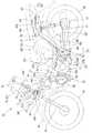
図1は本発明に係る自動二輪車の左側面図であり、自動二輪車10は、車体フレーム11と、この車体フレーム11に含まれ車体フレーム11の前端部を構成するヘッドパイプ12と、このヘッドパイプ12に挿嵌されるステアリング軸13と、ステアリング軸13から下方に延設されるフロントフォーク14およびステアリング軸13の上端部に延びている操向ハンドル15と、フロントフォーク14の下端部に操向可能に支持されている前輪16と、車体フレーム11の中央部に配置される駆動源としてのエンジン17と、車体フレーム11の後部に設けられているスイングアーム18L、18R(図手前側の符号18Lのみ示す。以下同じ。)と、これらのスイングアーム18L、18Rに揺動自在に支持されている後輪19と、を備えている。 FIG. 1 is a left side view of a motorcycle according to the present invention. A
車体フレーム11は、ヘッドパイプ12と、ヘッドパイプ12から斜め下後方に延設される1本のメインフレーム21と、メインフレーム21の中間部から後方に、且つ、左右外方に水平に延設された後、後斜め上方に延設されている左右のサブフレーム22L、22R(図手前側の符号22Lのみ示す。以下同じ。)と、メインフレーム21の後部と左右のサブフレーム22L、22Rから垂下されスイングアーム18L、18Rのピボット軸28を有する左右のピボットプレート29L、29R(図手前側の符号29Lのみ示す。以下同じ。)と、左右のサブフレーム22L、22Rの後端部から後方に延設されるとともに、平面視で、略U字状を呈するリヤフレーム32と、サブフレーム22L、22Rとリヤフレーム32の間に設けられリヤクッションユニット33L、33R(図手前側の符号33Lのみ示す。以下同じ。)の上端部が取り付けられるクッションブラケット34L、34R(図手前側の符号34Lのみ示す。以下同じ。)と、を主要な構成要素とする。 The
エンジン17は、車体フレーム11に懸架されており、後部に変速機が一体的に設けられている変速機部36と、変速機部36の前部にシリンダ38が設けられ、このシリンダ38にシリンダヘッド39が設けられ、このシリンダヘッド39の上部に吸気装置41が接続され、シリンダヘッド39の下部に排気装置42が接続されている。 The
吸気装置41は、一端がシリンダヘッド39に、吸気管44を介して接続されているスロットルボデイ45と、このスロットルボデイ45の他端に接続されたエアクリーナ46とからなる。また、排気装置42は、シリンダヘッド39の下部に一端が接続されてエンジン17から下方へそして後方に延びる排気管48と、この排気管48の他端に接続されて後方に延びる消音器49と、からなる。 The intake device 41 includes a
車体の後部構造について説明すると、左右のサブフレームの間に物入れとしての収納ボックス51が取り付けられ、この収納ボックス51の後方に燃料タンク52が配置され、収納ボックス51から燃料タンク52の上方にわたり、ヒンジ部53を介して開閉可能に着座用の乗員シート54が設けられている。56は収納ボックス51に収納されているヘルメットである。 The rear structure of the vehicle body will be described. A
車体フレーム11の外方は、車体カバー58で覆われている。車体カバー58は、ヘッドパイプ12の周囲を覆う車体前部カバー61と、乗員シート54を含む車体後部を覆う車体後部カバー62と、からなる。 The outside of the
車体前部カバー61は、車体の前面を構成するフロントカバー63と、このフロントカバー63の後方に連続して設けられ乗員の膝の前方を覆うインナカバーとしてのレッグシールド64とからなる。ヘッドパイプ12の周囲を覆う車体前部カバー61の内側に、且つ、ヘッドパイプ12の周囲に、車両の位置情報を検出するとともにこの位置情報を無線送信する盗難対策装置66が配置されている。盗難対策装置66の詳細については、後述する。 The vehicle
図中、68はエンジン17の出力軸69に設けたドライブギヤ、71はチェーン、72はスプロケット、73はメインスタンド、74はフロントフェンダ、75はヘッドランプ、76は車体後部に配置されてエンジンを制御するエンジン制御ユニット、77はテールランプ(テールランプユニット)である。 In the figure, 68 is a drive gear provided on the
図2は本発明の自動二輪車に備えられている盗難対策装置およびその周辺部のブロック図であり図1を併せて参照し説明を行う。
盗難対策装置66は、車両(自動二輪車)の車体に加えられた振動を検知する加速度センサ81と、複数の人工衛星から軌道情報を受信することにより車両の現在位置を検出する全地球測位システム(Global Positioning System)82と、加速度センサ81からの加速度信号SAおよび全地球測位システム82からの位置情報JPを受けて盗難対策を指令する制御部83と、制御部83からの交信指令SCに基づいて衛星携帯電話機84へ位置情報JPを送信する衛星携帯電話システム85と、制御部83からのエンジン制御信号SECに基づきエンジンの点火装置86に点火停止信号SSSを送って点火装置86の作動を停止させる、すなわち、エンジン17を停止させるエンジン制御部87と、制御部83からの警報制御信号SACに基づき警報装置88(ヘッドランプ75、ウインカ(図3の符号91)、テールランプ77等の灯火器93、ホーン(図4の符号94))に警報信号SAを送って灯火器93、ホーン94を作動させる警報発生部96と、内部電源98と、からなる。
内部電源98としては、例えば、リチウム電池が利用される。FIG. 2 is a block diagram of the anti-theft device provided in the motorcycle of the present invention and its peripheral portion, which will be described with reference to FIG.
The
As the
全地球測位システム82および衛星携帯電話システム85とを備える盗難対策装置66を車体を構成するヘッドパイプ12の周囲で、且つ、車体前部カバー61の内側に配置することで、衛星からの軌道情報の受信および位置情報の送信を行う際に、盗難対策装置66の上方を完全に覆ってしまう程の金属製の構造物が存在しないため、電波が遮られないので、送受信感度が良好になり、盗難対策装置66の配置自由度が低い自動二輪車であっても盗難対策装置を良好に作動させることができる。 Orbit information from the satellite is provided by arranging a
図3は本発明に係る自動二輪車に備えられている盗難対策装置の配置構造を説明する側面図、図4は本発明に係る自動二輪車に備えられている盗難対策装置の配置構造を説明する正面図、図5は本発明に係る自動二輪車に備えられている盗難対策装置の配置構造を説明する斜視図である。以下、図3〜図5を参照して説明を行う。 FIG. 3 is a side view for explaining the arrangement structure of the antitheft device provided in the motorcycle according to the present invention, and FIG. 4 is a front view for explaining the arrangement structure of the antitheft device provided in the motorcycle according to the present invention. FIG. 5 and FIG. 5 are perspective views for explaining the arrangement structure of the antitheft device provided in the motorcycle according to the present invention. Hereinafter, description will be given with reference to FIGS.
ヘッドパイプ12の周囲で、車体前部カバー61の内側に、バッテリ111を収納するバッテリケース112が設けられている。具体的には、バッテリケース112は、ヘッドパイプ12の前側に配置されている。
盗難対策装置66は、ヘッドパイプ12の側方に配置されているので、ヘッドパイプ12の上側または下側に盗難対策装置66が大きく突出することを防止することができ、盗難対策装置66を、フロントフェンダ74や操向ハンドル15などの操向系部材と距離を確保し易く、自由に配置することができる。A
Since the
バッテリケース112は、前面が開放され、上面113と、この上面113の両端部から下方に延びている左右の壁部114、115と、左右の壁部114、115の間に設けられる下面116と、後面117とによって囲まれバッテリ111が収納される収納部118を備えている箱状の部材であり、ヘッドパイプ12の前部に付設されているバッテリケース112の取付ブラケットとしての固定部121に、3つの締結部材122・・・(・・・は複数を示す。)を介して取り付けられている。なお、バッテリケース112は、樹脂製である。 The
バッテリケース112の上面113から上方に、フロントカバー63の内面に後方に突設された突起124を支持する孔部125を有するカバ−支持部126が延びており、このカバ−支持部126の孔部125に突起124が挿入され、フロントカバー63が支持されている。 A
以下、盗難対策装置66の取付構造につき詳細に説明する。
バッテリケース112の左壁部114から左側に、且つ、略水平に、盗難対策装置66を支持する第1支持腕131が延設されている。また、ヘッドパイプ12から左側に、且つ。略水平に、盗難対策装置66を支持する第2支持腕132が延設されている。Hereinafter, the mounting structure of the
A
第1および第2支持腕131、132の先端部は、第1および第2支持腕131、132に、後述する盗難対策装置66側に設けた第1および第2係合部133、134が係合されたときに、第1および第2係合部133、134が第1および第2支持腕131、132から抜けないようにするために通常よりも支持腕の幅よりも幅広に形成された抜止部135、136を備えている。 The distal ends of the first and
一方、盗難対策装置66は、前方を向く前面141に第1および第2コネクタ部142、143とからなるコネクタ部144を備え、後面145と上面146と左右の側面147、148と下面149とを備えユニットを形成する6面体のケース体151を含み、このケース体151の長手方向が、車両前後方向に沿うように配置されている。
コネクタ部144は、エンジン(図1の符号17)を制御するエンジン制御ユニット76とバッテリ111とに接続される。On the other hand, the
The
盗難対策装置66は、コネクタ部144が前方に向けた状態で配置されるとともに、コネクタ部144の幅は、前面視で、盗難対策装置66を囲うケース体151の幅よりも小さい。
コネクタ部144には、配線が接続されるため、コネクタ部144の周辺は、配線のはいまわしなどを考慮して、ある程度のスペースが必要になるが、コネクタ部144は、前面視で、ケース体151よりも小さく設けられているので、車体前部カバー61のヘッドパイプ前方に位置するスペースを車幅方向に確保し易くすることができる。ヘッドパイプ前方のスペースが車幅方向に確保され易くなれば、車体前部カバー61が車幅方向に大きくなることを回避することができるような位置にコネクタ部144を配置することができる。The
Since wiring is connected to the
また、盗難対策装置66は、バッテリケース112の側方に配置され、その長手方向が、車両前後方向に沿うように配置されているので、車体前部カバー61が車幅方向に大型化することを抑えることができる。 Further, since the
さらに、盗難対策装置66は、バッテリケース112の下方に配置されているので、バッテリケース112の上方に盗難対策装置66を配置する場合に較べて、車両の重心を下げることができる。また、バッテリ111の上部に配置したプラス端子171およびマイナス端子172に接続される配線(コード)の邪魔にならない。 Furthermore, since the
以下、盗難対策装置のボックスとしてのケース体151に装着され、第1および第2支持腕131、132との間に介在され衝撃吸収機能およびブラケット機能をもつように形成されている弾性部材の詳細につき説明する。
ケース体151の外側に、ケース体151を囲うように、例えば、衝撃を吸収する弾性部材152が装着されている。弾性部材152は、ラバーを利用したが、樹脂などの部材であっても良い。Hereinafter, details of the elastic member that is attached to the
For example, an
弾性部材152は、ケース体151の上面146と左右の側面147、148と下面149の周囲を囲うように装着される第1保持部153と、この第1保持部153から後方に延びており、ケース体151の上面146と後面145と下面149の周囲を囲うように装着される第2保持部154と、第1保持部153に設けられケース体151の上面146に対応する部分に第1凸部155が形成され、この第1凸部155に第1支持腕131が挿入される第1係合穴156が設けられ、第2保持部154に設けられケース体151の下面149に対応する部分に第2凸部157が形成され、この第2凸部157に第2支持腕132が挿入される第2係合穴158が設けられている。そして、第1および第2支持腕131、132によって盗難対策装置66を挟持するようにした。
盗難対策装置66は、バッテリーケース112およびヘッドパイプ12によって支持されている部材である。The
The
バッテリケース112は、重量物であるバッテリ111を支持するために剛性が確保されているので、盗難対策装置66を剛性の高いバッテリケース112で容易に支持させることができる。バッテリケース112に盗難対策装置66の支持部材を兼ねさせたので、部品点数の増加を抑えることができる。 Since the
また、盗難対策装置66は、バッテリ111と近接配置されているので、盗難対策装置66とバッテリ111間をつなぐ配線を短くすることができる。配線が短くなれば、配線長さが短くなることによる車両コストの低減および車両の軽量化を図ることができる。 Further, since the
盗難対策装置66は、バッテリケース112の側方に配置されている。バッテリケース112の側方にあれば、盗難対策装置66がバッテリケース112の上側または下側に大きく突出することを防止でき、また、盗難対策装置66を、フロントフェンダ(図の符号74)や操向ハンドル(図の符号15)などの操向系部材との干渉に配慮することなく、自由に配置することができる。本実施例において、盗難対策装置66は、バッテリケース112の左側に配置されている。 The
盗難対策装置66に、ケース体151が設けられ、このケース体151の最も大きな面としての上面146が水平又は水平に近く配置されているため、盗難対策装置66内の機能部品の配置を最適化した上で、アンテナの面積を確保することができ、送受信を良好にすることができる。Ideal for
以上に述べた盗難対策装置の配置構造の作用を次に述べる。
盗難対策装置66は、ヘッドパイプ12の周囲に形成される空間に配置されている。
従来、盗難対策装置が、収納ボックス内に配置される場合には、収納ボックスの容量に配慮する必要があり、配置自由度に制約があった。The operation of the above-described antitheft device arrangement structure will be described next.
The
Conventionally, when an antitheft device is arranged in a storage box, it is necessary to consider the capacity of the storage box, and there is a restriction on the degree of freedom of arrangement.
この点、本発明では、盗難対策装置66は、車体前部カバー61の内側に、且つ、ヘッドパイプ12の周囲に配置されているので、収納ボックス51の容量に配慮することなく、自由に盗難対策装置66を配置することができ、配置自由度を高めることができる。 In this regard, in the present invention, since the
加えて、盗難対策装置66は、車体前部カバー61の内側に配置されているので、良好な防水性を確保することができる。さらに、人目につき難い位置となるので、秘匿性を確保することができる。 In addition, since the
図4に戻って、車体前部カバー61の下部は、車両下方に向かうにしたがいヘッドパイプ12から離れるように末広がりに構成されているので、盗難対策装置66を広い空間に配置することが可能となり、配置自由度を一層高めることができる。 Returning to FIG. 4, the lower part of the
図2を併せて参照して、盗難対策装置66は、全地球測位システム82と衛星携帯電話システム85と加速度センサ81と制御部83と内部電源98とを一体のユニット内に備えている。すなわち、ケース体151の内側に、全地球測位システム82と衛星携帯電話システム85と加速度センサ81と制御部83と内部電源98とが全て収納されている。 Referring also to FIG. 2, the
盗難対策装置66のシステムを一体のユニット内であるケース体151に収めるため、車両への組付性を向上させることができる。 Since the system of the
盗難対策装置66は、エンジン停止機能と警報機能とを有し、盗難対策装置66を車体に備える電装系統を構成する灯火器93、ホーン94などに接続するようにした。
車体に備える灯火器93、ホーン94などに盗難対策装置66を接続することにより、エンジン停止機能と警報機能とを作動させることができるため、新たな機能部品を配置したり、配線を増やしたりする必要がない。The
Since the
図6は第2実施の形態に係る自動二輪車に備えられている盗難対策装置の配置構造を説明する側面図であり、図1を併せて参照し説明を行う。
エンジン17を制御するエンジン制御ユニット76は、ヘッドパイプ12の後方に配置され、盗難対策装置66Bに、エンジン制御ユニット76とバッテリ111とに接続されるコネクタ部144Bが設けられ、盗難対策装置66Bは、コネクタ部144Bを後方に向けた状態で配置されている。FIG. 6 is a side view for explaining the arrangement structure of the antitheft device provided in the motorcycle according to the second embodiment, which will be described with reference to FIG.
The
エンジン制御ユニット76Bは、ヘッドパイプ12の後方で燃料タンク52の側方に配置され、盗難対策装置66Bは、コネクタ部144Bを後方に向けた状態で配置されているので、エンジン制御ユニット76と盗難対策装置66Bとの間をつなぐ配線を短くすることができる。 The engine control unit 76B is disposed behind the
図7は第3実施の形態に係る自動二輪車に備えられている盗難対策装置の配置構造を説明する側面図であり、図6と大きく異なる点は、バッテリケース112の下面116に、下方に開いたコ字状のステー161が付設され、このステー161に盗難対策装置66Cがコネクタ部144を左側に向けて配置されている。この場合に、盗難対策装置66Cの長手方向は、車両の幅方向と平行な方向であり、バッテリケース112から前方に突出するように配置される。
盗難対策装置66Cは、バッテリケース112の下方に配置されているので、バッテリケース122の側方に盗難対策装置を配置する場合に較べて、フロントカバー63を幅方向で小さくすることができる。
その他、図6と大きく変わるところはなく、説明を省略する。FIG. 7 is a side view for explaining the arrangement structure of the antitheft device provided in the motorcycle according to the third embodiment. The difference from FIG. 6 is that the
Since the
In addition, there is no significant difference from FIG.
図8は第4実施の形態に係る自動二輪車に備えられている盗難対策装置の配置構造を説明する側面図、図9は第4実施の形態に係る自動二輪車に備えられている盗難対策装置の配置構造を説明する平面図である。以下、図8〜図9を参照して説明を行う。
図7と大きく異なる点は、ヘッドパイプ12から、前方で、略水平方向に、平面視で、5角形に形成された金属製のステー部材162が延設されこのステー部材162に、上方から、盗難対策装置66Dが、弾性部材152Dを介して装着されている。図中、163・・・は、ステー部材162に設けられ、鉛直方向上向きに延設され弾性部材152Dと係合する爪部である。その他、図7と大きく変わるところはなく、説明を省略する。
盗難対策装置66Dは、ヘッドパイプ12の前方に配置されているので、車体前部カバー61のヘッドパイプ12の後方部分が大きくなることを防止することができる。
盗難対策装置66は略水平に配置され、ボックスとしてのケース体151の上方は、金属で遮蔽されていないため、アンテナの面積を確保することができ、送受信を良好にすることができる。FIG. 8 is a side view for explaining an arrangement structure of the antitheft device provided in the motorcycle according to the fourth embodiment, and FIG. 9 is an illustration of the antitheft device provided in the motorcycle according to the fourth embodiment. It is a top view explaining an arrangement structure. Hereinafter, description will be given with reference to FIGS.
A significant difference from FIG. 7 is that a
Since the
The
以下、図10〜図13では、盗難対策装置が、車体前部カバー61側に取り付けられている場合について説明する。
図10は第5実施の形態に係る自動二輪車に備えられている盗難対策装置の配置構造を説明する側面図であり、車体前部カバー61の前部内面61fから水平方向後方に、水平ステー164、165が延設され、これらの水平ステー164、165に、盗難対策装置66Eのケース体151Eが装着されている。取付構造は、前述した第1実施例と大きく変わるところはない。Hereinafter, in FIG. 10 to FIG. 13, a case where the antitheft device is attached to the vehicle
FIG. 10 is a side view for explaining the arrangement structure of the antitheft device provided in the motorcycle according to the fifth embodiment. The
図11は第6実施の形態に係る自動二輪車に備えられている盗難対策装置の配置構造を説明する側面図であり、盗難対策装置66Fは、車体前部カバー61の前部内面61fに取り付けられている。取付構造は、前述した第1実施例と大きく変わるところはない。具体的には、車体前部カバー61の内面に、複数の爪部材166・・・を立設し、これらの爪部材166・・・に、ケース体151側に設けた係合部133F、134Fを係合する。 FIG. 11 is a side view for explaining the arrangement structure of the antitheft device provided in the motorcycle according to the sixth embodiment. The
図12は第7実施の形態に係る自動二輪車に備えられている盗難対策装置の配置構造を説明する側面図であり、盗難対策装置66Gは、ヘッドパイプ12の前方にある車体前部カバー61の上部内面61tに取り付けられている。最も広い面である上面146Gが略水平方向に配置されているので、アンテナの面積を確保することができ、送受信を良好にすることができる。
なお、取付構造は、前述した第1実施例と大きく変わるところはなく説明を省略する。FIG. 12 is a side view for explaining the arrangement structure of the anti-theft device provided in the motorcycle according to the seventh embodiment. The
The mounting structure is not greatly different from that of the first embodiment described above, and a description thereof is omitted.
図13は第8実施の形態に係る自動二輪車に備えられている盗難対策装置の配置構造を説明する側面図であり、盗難対策装置66Hは、ヘッドパイプ12の後方に設けられる車体前部カバー61の後部内面61rに取り付けられている。盗難対策装置66Hは、ヘッドパイプ12の後方に配置されているので、車体前部カバー61のヘッドパイプ12の前方部分が大きくなることを防止することができる。 FIG. 13 is a side view for explaining the arrangement structure of the anti-theft device provided in the motorcycle according to the eighth embodiment. The
尚、本発明は、実施の形態では自動二輪車に適用したが、三輪車にも適用可能であり、一般の車両に適用することは差し支えない。 Although the present invention is applied to a motorcycle in the embodiment, it can also be applied to a tricycle and can be applied to a general vehicle.
本発明は、盗難対策装置が備えられている自動二輪車に好適である。 The present invention is suitable for a motorcycle equipped with a theft countermeasure device.
10…自動二輪車、11…車体フレーム、12…ヘッドパイプ、16…前輪、17…エンジン、18L、18R…スイングアーム、19…後輪、58…車体カバー、61…車体前部カバー、63…フロントカバー、64…インナカバー、66、66B、66C、66DE、66E、66F、66G、66H…盗難対策装置、76…エンジン制御ユニット、81…加速度センサ、82…全地球測位システム、83…制御部、85…衛星携帯電話システム、93…灯火器、98…内部電源、111…バッテリ、112…バッテリケース、144…コネクタ部、151…ケース体(ボックス)。
DESCRIPTION OF
Claims (7)
Translated fromJapanese前記車体カバー(58)は、前記ヘッドパイプ(12)の周囲を覆う車体前部カバー(61)を有し、
前記盗難対策装置(66)は、前記車体前部カバー(61)の内側に、且つ、前記ヘッドパイプ(12)の周囲に配置され、
前記ヘッドパイプ(12)の周囲で、前記車体前部カバー(61)の内側に、バッテリ(111)を収納するバッテリケース(112)が設けられ、このバッテリケース(112)に、前記盗難対策装置(66)が支持されていることを特徴とする自動二輪車。A vehicle body frame (11), a head pipe (12) included in the vehicle body frame (11), a front wheel (16) supported in a freely steerable manner by the head pipe (12), and the vehicle body frame (11) A rear wheel (19) that is swingably supported on the vehicle body, a vehicle body cover (58) that covers the vehicle body frame (11), and a theft countermeasure device that detects vehicle position information and wirelessly transmits the position information ( 66), and a motorcycle equipped with
The vehicle body cover (58) has a vehicle body front cover (61) covering the periphery of the head pipe (12),
The antitheft device (66) is arranged inside the vehicle body front cover (61) and around the head pipe (12),
A battery case (112) for storing a battery (111) is provided around the head pipe (12) and inside the vehicle body front cover (61), and the antitheft device is provided in the battery case (112). (66) is supported, The motorcycle characterized by the above-mentioned.
このコネクタ部(144)を前方に向けた状態で、前記盗難対策装置(66)が配置され、前記コネクタ部(144)は、前面視で、前記盗難対策装置(66)を囲うケース体の幅よりも小さいことを特徴とする請求項1又は請求項2記載の自動二輪車。The battery case (112) is disposed on the front side of the head pipe (12), and is connected to the antitheft device (66) by an engine control unit (76) for controlling the engine (17) and the battery (111). A connector part (144) to be connected is provided,
The antitheft device (66) is arranged with the connector portion (144) facing forward, and the connector portion (144) is a width of a case body that surrounds the antitheft device (66) when viewed from the front. The motorcycle according to claim 1 or2 , wherein the motorcycle is smaller.
前記盗難対策装置(66)は、前記コネクタ部(144)が、前記フロントカバー(63)側に位置するように配置されていることを特徴とする請求項3記載の自動二輪車。The vehicle body front cover (61) is disposed in front of the head pipe (12), and is disposed in front of the front pipe (63) covering the head pipe (12) from the front, and behind the head pipe (12). An inner cover (64) covering the head pipe (12) from the rear,
The motorcycle according to claim3 , wherein the anti-theft device (66) is arranged so that the connector portion (144) is positioned on the front cover (63) side.
前記盗難対策装置(66)に、前記エンジン制御ユニット(76)と前記バッテリ(111)とに接続されるコネクタ部(144)が設けられ、
前記盗難対策装置(66)は、前記コネクタ部(144)を後方に向けた状態で配置されていることを特徴とする請求項1又は請求項2記載の自動二輪車。An engine control unit (76) for controlling the engine (17) is disposed behind the head pipe (12),
The antitheft device (66) is provided with a connector part (144) connected to the engine control unit (76) and the battery (111),
The motorcycle according to claim 1 or2, wherein the antitheft device (66) is arranged with the connector portion (144) facing rearward.
Priority Applications (2)
| Application Number | Priority Date | Filing Date | Title |
|---|---|---|---|
| JP2008282203AJP5222693B2 (en) | 2008-10-31 | 2008-10-31 | Motorcycle |
| BRPI0904453-1ABRPI0904453B1 (en) | 2008-10-31 | 2009-10-29 | MOTORCYCLE |
Applications Claiming Priority (1)
| Application Number | Priority Date | Filing Date | Title |
|---|---|---|---|
| JP2008282203AJP5222693B2 (en) | 2008-10-31 | 2008-10-31 | Motorcycle |
Publications (2)
| Publication Number | Publication Date |
|---|---|
| JP2010105630A JP2010105630A (en) | 2010-05-13 |
| JP5222693B2true JP5222693B2 (en) | 2013-06-26 |
Family
ID=42295487
Family Applications (1)
| Application Number | Title | Priority Date | Filing Date |
|---|---|---|---|
| JP2008282203AExpired - Fee RelatedJP5222693B2 (en) | 2008-10-31 | 2008-10-31 | Motorcycle |
Country Status (2)
| Country | Link |
|---|---|
| JP (1) | JP5222693B2 (en) |
| BR (1) | BRPI0904453B1 (en) |
Families Citing this family (4)
| Publication number | Priority date | Publication date | Assignee | Title |
|---|---|---|---|---|
| TWI394680B (en)* | 2011-03-22 | 2013-05-01 | Kwang Yang Motor Co | Integrated battery case |
| JP5667929B2 (en)* | 2011-05-23 | 2015-02-12 | 川崎重工業株式会社 | Motorcycle |
| JP6133111B2 (en)* | 2013-02-25 | 2017-05-24 | 本田技研工業株式会社 | Battery arrangement structure for saddle-ride type vehicles |
| JP2019155944A (en)* | 2018-03-07 | 2019-09-19 | ヤマハ発動機株式会社 | Saddle-riding type vehicle |
Family Cites Families (6)
| Publication number | Priority date | Publication date | Assignee | Title |
|---|---|---|---|---|
| JP3055705B2 (en)* | 1991-02-08 | 2000-06-26 | 本田技研工業株式会社 | Cooling structure of power unit for electric motorcycle |
| JP3847459B2 (en)* | 1998-07-03 | 2006-11-22 | 株式会社日進 | Vehicle anti-theft device |
| JP2002264874A (en)* | 2001-03-12 | 2002-09-18 | Toshiba Corp | Communication device for motorcycle, helmet and anti-theft device using this communication device |
| JP4189154B2 (en)* | 2001-04-02 | 2008-12-03 | 本田技研工業株式会社 | Motorcycle anti-theft device installation structure |
| JP2006199168A (en)* | 2005-01-21 | 2006-08-03 | Kawasaki Heavy Ind Ltd | Leisure vehicle anti-theft device |
| JP5144947B2 (en)* | 2006-07-07 | 2013-02-13 | ヤマハ発動機株式会社 | Vehicle anti-theft system and vehicle equipped with anti-theft system |
- 2008
- 2008-10-31JPJP2008282203Apatent/JP5222693B2/ennot_activeExpired - Fee Related
- 2009
- 2009-10-29BRBRPI0904453-1Apatent/BRPI0904453B1/enactiveIP Right Grant
Also Published As
| Publication number | Publication date |
|---|---|
| JP2010105630A (en) | 2010-05-13 |
| BRPI0904453B1 (en) | 2019-07-16 |
| BRPI0904453A2 (en) | 2010-09-21 |
Similar Documents
| Publication | Publication Date | Title |
|---|---|---|
| JP5086831B2 (en) | Motorcycle | |
| JP5412199B2 (en) | Motorcycle | |
| JPWO2012090243A1 (en) | Electric motorcycle | |
| JP5596012B2 (en) | Motorcycle | |
| JP5145198B2 (en) | Anti-theft device for motorcycles | |
| JP2014234116A (en) | Fuel cell vehicle | |
| JP5222693B2 (en) | Motorcycle | |
| JP5235176B2 (en) | Motorcycle | |
| JP5145196B2 (en) | Motorcycle | |
| CN101531228A (en) | Motorcycle | |
| JP5486966B2 (en) | Saddle riding | |
| JP5665696B2 (en) | Storage structure of saddle-ride type vehicle | |
| JP5042984B2 (en) | Motorcycle | |
| JP5358654B2 (en) | Motorcycle | |
| JP2012176755A (en) | Anti-theft device of motorcycle | |
| JP6083600B2 (en) | Arrangement structure of communication unit in saddle-ride type vehicle | |
| JP5235177B2 (en) | Motorcycle | |
| JP5520733B2 (en) | Saddle riding | |
| JP5469945B2 (en) | Motorcycle | |
| JP2013071675A (en) | Motorcycle | |
| JP5492948B2 (en) | Motorcycle | |
| JP5470104B2 (en) | Saddle riding | |
| JP5656923B2 (en) | Anti-theft device for motorcycles | |
| JP5597601B2 (en) | Saddle riding | |
| CN107867351B (en) | Storage box structure of saddle-type vehicle |
Legal Events
| Date | Code | Title | Description |
|---|---|---|---|
| A621 | Written request for application examination | Free format text:JAPANESE INTERMEDIATE CODE: A621 Effective date:20101126 | |
| A977 | Report on retrieval | Free format text:JAPANESE INTERMEDIATE CODE: A971007 Effective date:20120419 | |
| A131 | Notification of reasons for refusal | Free format text:JAPANESE INTERMEDIATE CODE: A131 Effective date:20120424 | |
| A521 | Written amendment | Free format text:JAPANESE INTERMEDIATE CODE: A523 Effective date:20120625 | |
| A131 | Notification of reasons for refusal | Free format text:JAPANESE INTERMEDIATE CODE: A131 Effective date:20121002 | |
| A521 | Written amendment | Free format text:JAPANESE INTERMEDIATE CODE: A523 Effective date:20121122 | |
| TRDD | Decision of grant or rejection written | ||
| A01 | Written decision to grant a patent or to grant a registration (utility model) | Free format text:JAPANESE INTERMEDIATE CODE: A01 Effective date:20130305 | |
| A61 | First payment of annual fees (during grant procedure) | Free format text:JAPANESE INTERMEDIATE CODE: A61 Effective date:20130311 | |
| FPAY | Renewal fee payment (event date is renewal date of database) | Free format text:PAYMENT UNTIL: 20160315 Year of fee payment:3 | |
| R150 | Certificate of patent or registration of utility model | Ref document number:5222693 Country of ref document:JP Free format text:JAPANESE INTERMEDIATE CODE: R150 Free format text:JAPANESE INTERMEDIATE CODE: R150 | |
| LAPS | Cancellation because of no payment of annual fees |