JP5221658B2 - Inclined valve stem actuator - Google Patents
Inclined valve stem actuatorDownload PDFInfo
- Publication number
- JP5221658B2 JP5221658B2JP2010521015AJP2010521015AJP5221658B2JP 5221658 B2JP5221658 B2JP 5221658B2JP 2010521015 AJP2010521015 AJP 2010521015AJP 2010521015 AJP2010521015 AJP 2010521015AJP 5221658 B2JP5221658 B2JP 5221658B2
- Authority
- JP
- Japan
- Prior art keywords
- overcap
- vibration motor
- valve stem
- dispensing system
- actuated
- Prior art date
- Legal status (The legal status is an assumption and is not a legal conclusion. Google has not performed a legal analysis and makes no representation as to the accuracy of the status listed.)
- Expired - Fee Related
Links
Images


Classifications
- A—HUMAN NECESSITIES
- A61—MEDICAL OR VETERINARY SCIENCE; HYGIENE
- A61L—METHODS OR APPARATUS FOR STERILISING MATERIALS OR OBJECTS IN GENERAL; DISINFECTION, STERILISATION OR DEODORISATION OF AIR; CHEMICAL ASPECTS OF BANDAGES, DRESSINGS, ABSORBENT PADS OR SURGICAL ARTICLES; MATERIALS FOR BANDAGES, DRESSINGS, ABSORBENT PADS OR SURGICAL ARTICLES
- A61L9/00—Disinfection, sterilisation or deodorisation of air
- A61L9/14—Disinfection, sterilisation or deodorisation of air using sprayed or atomised substances including air-liquid contact processes
- B—PERFORMING OPERATIONS; TRANSPORTING
- B65—CONVEYING; PACKING; STORING; HANDLING THIN OR FILAMENTARY MATERIAL
- B65D—CONTAINERS FOR STORAGE OR TRANSPORT OF ARTICLES OR MATERIALS, e.g. BAGS, BARRELS, BOTTLES, BOXES, CANS, CARTONS, CRATES, DRUMS, JARS, TANKS, HOPPERS, FORWARDING CONTAINERS; ACCESSORIES, CLOSURES, OR FITTINGS THEREFOR; PACKAGING ELEMENTS; PACKAGES
- B65D83/00—Containers or packages with special means for dispensing contents
- B65D83/14—Containers for dispensing liquid or semi-liquid contents by internal gaseous pressure, i.e. aerosol containers comprising propellant
- B65D83/16—Actuating means
- B65D83/26—Actuating means operating automatically, e.g. periodically
- B65D83/262—Actuating means operating automatically, e.g. periodically by clockwork, motor, electric or magnetic means operating without repeated human input
- B—PERFORMING OPERATIONS; TRANSPORTING
- B65—CONVEYING; PACKING; STORING; HANDLING THIN OR FILAMENTARY MATERIAL
- B65D—CONTAINERS FOR STORAGE OR TRANSPORT OF ARTICLES OR MATERIALS, e.g. BAGS, BARRELS, BOTTLES, BOXES, CANS, CARTONS, CRATES, DRUMS, JARS, TANKS, HOPPERS, FORWARDING CONTAINERS; ACCESSORIES, CLOSURES, OR FITTINGS THEREFOR; PACKAGING ELEMENTS; PACKAGES
- B65D83/00—Containers or packages with special means for dispensing contents
- B65D83/14—Containers for dispensing liquid or semi-liquid contents by internal gaseous pressure, i.e. aerosol containers comprising propellant
- B65D83/44—Valves specially adapted for the discharge of contents; Regulating devices
- B65D83/46—Tilt valves
Landscapes
- Health & Medical Sciences (AREA)
- Life Sciences & Earth Sciences (AREA)
- Engineering & Computer Science (AREA)
- Mechanical Engineering (AREA)
- Dispersion Chemistry (AREA)
- Epidemiology (AREA)
- Chemical & Material Sciences (AREA)
- Animal Behavior & Ethology (AREA)
- General Health & Medical Sciences (AREA)
- Public Health (AREA)
- Veterinary Medicine (AREA)
- Containers And Packaging Bodies Having A Special Means To Remove Contents (AREA)
- Nozzles (AREA)
Description
Translated fromJapanese本開示は容器用オーバーキャップに関し、より詳しくは、傾斜作動式バルブステムを有するエアゾール容器に配置されるべく適合されたオーバーキャップに関する。 The present disclosure relates to container overcaps, and more particularly to an overcap adapted to be placed in an aerosol container having a tilt-actuated valve stem.
エアゾール容器は、エアフレッシュナ、脱臭剤、殺虫剤、殺菌剤、充血除去薬、芳香などの揮発性物質を保管しディスペンス(放出)するために使用されることが一般的である。通常、揮発性物質は、圧縮された状態且つ液体状態で容器内に保管される。容器のリリースバルブは、圧縮された状態で収容されている揮発性物質の放出を制御する。通常、リリースバルブはバルブから外方向に延出するバルブステムを有する。バルブはバルブステムによって作動され、揮発性物質はバルブステムを通じて容器から流出する。このようなリリースバルブにおいて、バルブステムがバルブ本体に対して移動するとバルブが作動される。バルブステムはバルブステムの長手軸に沿って、すなわち軸方向に沿って移動してもよい。あるいは、バルブステムはバルブステムの長手軸を横切る方向、すなわち半径方向に傾斜され又は移動されてもよい。 Aerosol containers are commonly used to store and dispense volatile materials such as air fresheners, deodorants, insecticides, bactericides, decongestants, aromas, and the like. Usually, volatile substances are stored in containers in a compressed and liquid state. The release valve of the container controls the release of volatile material contained in a compressed state. Typically, release valves have a valve stem that extends outwardly from the valve. The valve is actuated by the valve stem, and volatile material flows out of the container through the valve stem. In such a release valve, the valve is activated when the valve stem moves relative to the valve body. The valve stem may move along the longitudinal axis of the valve stem, ie along the axial direction. Alternatively, the valve stem may be tilted or moved in a direction transverse to the longitudinal axis of the valve stem, ie in a radial direction.
リリースバルブは自動システムにより作動されてもよく、あるいは手動で作動されてもよい。手動で作動される場合、ユーザは所望の放出を得るために要求される、バルブに付与される作動力を調節することができる。従って、一般的に、付与される力の要件を考察することは、手動で作動されるリリースバルブの設計においてはさほど重要でない。従来の作動装置機構には、ノズルを押下して容器内のバルブを開くために下方圧力を加える、モータで駆動されるリンケージを含むものがある。このような作動装置機構は一般的に使いにくい上、立ててあるいは手に持って使用するには適応が容易でない。また、このような作動装置機構では電力消費量が大きいことが多い。一般的に、傾斜作動式バルブステムを有するバルブは、垂直方向に作動されるバルブステムを有するバルブと比べ、作動に要する力が小さくてすむ。従って、作動の際に要する電力が小さいことから、作動力が小さくてすむリリースバルブは有利である。電力消費量が小さいため電源の耐用年数は長くなる。要求される力が小さいため、単純、小型及び/又は低コストの自動設計が可能となることから、作動力が小さいことは自動作動にも有利である。 The release valve may be actuated by an automated system or may be actuated manually. When manually actuated, the user can adjust the actuating force applied to the valve required to obtain the desired release. Thus, in general, considering the applied force requirements is less important in the design of manually operated release valves. Some conventional actuator mechanisms include a motor driven linkage that applies a downward pressure to depress a nozzle and open a valve in the container. Such an actuator mechanism is generally difficult to use and is not easy to adapt when used upright or in hand. Also, such an actuator mechanism often consumes a large amount of power. In general, a valve having a tilt-actuated valve stem requires less force to operate than a valve having a valve stem that is actuated in the vertical direction. Therefore, a release valve that requires a small actuation force is advantageous because less power is required for actuation. Since the power consumption is small, the service life of the power supply is prolonged. Since the required force is small, a simple, small and / or low-cost automatic design is possible, so that a small operating force is also advantageous for automatic operation.
傾斜作動式バルブステムを有するバルブ用の既存の自動バルブ作動システムには、複雑且つ製造が困難なものがある。ギヤ、スプリング及び多数の可動部の正確な相互作用を含む複合システムの製造は高コストであり、また、複合システムは容器のオーバーキャップに嵌めるにはサイズが大きすぎる場合がある。また、複合システムの動作は多量の電力を必要とし、また構造が単純なシステムと比べてかなり故障しやすい。 Some existing automatic valve actuation systems for valves with tilt actuated valve stems are complex and difficult to manufacture. Manufacture of a composite system that includes the precise interaction of gears, springs and multiple moving parts is expensive and the composite system may be too large to fit into a container overcap. In addition, the operation of a complex system requires a large amount of power and is much more prone to failure than a system with a simple structure.
本発明の一態様によれば、ディスペンスシステム(放出システム)は、容器のバルブに操作可能に接続された、傾斜作動式バルブステムと、バルブステムと連通する振動モータと、を含み、振動モータは、作動されるとバルブステムに半径方向運動を付与すべく適合される。 According to one aspect of the present invention, a dispensing system includes a tilt-actuated valve stem operably connected to a valve of a container and a vibration motor in communication with the valve stem, the vibration motor being When actuated, adapted to impart radial motion to the valve stem.
本発明の別の態様によれば、揮発性物質容器用オーバーキャップは、バルブに操作可能に接続される、傾斜作動式バルブステムを有する容器に取り付けられるべく適合されたハウジングを含む。振動モータはハウジング内に配置される。振動モータはバルブステムに半径方向変位を付与すべく適合される。 In accordance with another aspect of the present invention, a volatile material container overcap includes a housing adapted to be attached to a container having a tilt-actuated valve stem operably connected to the valve. The vibration motor is disposed in the housing. The vibration motor is adapted to impart a radial displacement to the valve stem.
本発明の更に別の態様によれば、揮発性物質容器用オーバーキャップは、バルブに操作可能に接続される、傾斜作動式バルブステムを有する容器に取り付けられるべく適合されたハウジングを含む。振動モータはハウジング内に配置される。振動モータはタイマ、センサ又は手動の作動装置のうち少なくとも1つからの信号に応じて作動され、バルブステムに半径方向変位を付与すべく適合される。 In accordance with yet another aspect of the invention, a volatile material container overcap includes a housing adapted to be attached to a container having a tilt-actuated valve stem operably connected to the valve. The vibration motor is disposed in the housing. The vibration motor is actuated in response to a signal from at least one of a timer, a sensor or a manual actuating device and is adapted to impart a radial displacement to the valve stem.
本発明の別の態様において、液体をディスペンスする方法は、バルブに操作可能に接続される、傾斜作動式バルブステムを容器に設ける。異なるステップは、バルブステムに振動動作を付与する、ことを含み、振動動作はバルブステムに半径方向運動を付与する。 In another aspect of the invention, a method of dispensing a liquid includes providing a container with a tilt-actuated valve stem operably connected to a valve. The different steps include imparting a vibrating motion to the valve stem, the vibrating motion imparting a radial motion to the valve stem.
本発明の別の態様において、ディスペンスシステムは、容器上に設けられる、バルブに操作可能に接続される、傾斜作動式バルブステムを含む。作動機構はバルブステムと振動連通する。作動機構は作動されるとバルブステムに半径方向運動を付与すべく適合される。 In another aspect of the invention, the dispensing system includes a tilt-actuated valve stem operably connected to a valve provided on the container. The actuation mechanism is in vibration communication with the valve stem. The actuation mechanism is adapted to impart radial motion to the valve stem when actuated.
本発明の更に別の態様において、ディスペンスシステムは、容器上に設けられる、バルブに操作可能に接続される、傾斜作動式バルブステムを含む。傾斜作動式バルブステムは非作動状態にあるとき非作動位置に配置される。傾斜作動式バルブステムは、作動状態にあるとき第一の作動位置と第二の作動位置との間で移動される。第一及び第二の作動位置は、非作動位置から半径方向にオフセットされている。 In yet another aspect of the invention, the dispensing system includes a tilt-actuated valve stem that is operably connected to a valve provided on the container. The tilt-actuated valve stem is placed in a non-actuated position when in a non-actuated state. The tilt actuated valve stem is moved between a first operating position and a second operating position when in the actuated state. The first and second operating positions are radially offset from the non-operating position.
本発明の他の態様及び利点は以下の詳細な説明を考察することで明白となる。同様の構造は同様の参照数字にて示される。 Other aspects and advantages of the present invention will become apparent upon consideration of the following detailed description. Similar structures are indicated with similar reference numerals.
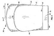
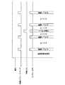
図1〜図6は、長手軸14に沿った長手方向寸法及び半径方向軸16に沿った半径方向寸法を有する略円筒状ハウジング12を有する、作動装置オーバーキャップ10を表す。ハウジング12はベース部18及び除去可能キャップ20を含む。ベース部18は、図7に示す従来のエアゾール容器26の上端24に保持されるべく適合された円筒状部22を含む。ベース部18については以下に詳述する。ポスト28は、円筒状部22の上端30から上方へ延出する。ポスト28の外壁には楕円形状の押しボタン34を有する湾曲した遠位端32が設けられる。押しボタン34は、更に凹部36を有する。押しボタン34に略対向するポスト28の内壁40(図9を参照)には円筒状ロッド38(図8参照)が設けられる。 1-6 illustrate an
除去可能キャップ20は、円筒状部22の上端30の直径と略等しい直径を有する円筒状底部42を含む。側壁44は除去可能キャップ20の底部42と頂部46との間に延在する。側壁44は、除去可能キャップ20の底部42に隣接する部分における断面直径が頂部46に隣接する部分における断面直径よりも小さくなるように、除去可能キャップ20の長手軸14に沿って外方向にテーパ状とされている。除去可能キャップ20の均等なテーパリングは、段差部48により切断される。段差部48は除去可能キャップ20の長手軸14の内方に延出する第一及び第二のテーパ面50及び52を含む。第一及び第二のテーパ面50及び52は、除去可能キャップ20の底部42に隣接する溝58の対向側に配置される第一の端部54、56をそれぞれ含む。テーパ面50及び52は、第一の端部54及び56から、除去可能キャップ20の、溝58に対向し且つ頂部46に隣接する部分60に向けて上方に湾曲している。 The
除去可能キャップ20の上面62は凸面であり、周囲に円形の周縁64を有する。上面62の中央に楕円形状の放出オリフィス66が配置される。円錐台形壁68は、放出オリフィス66の周縁に沿って除去可能キャップ20の内部へ垂下する。湾曲した溝70は、放出オリフィス66と周縁64の間に配置される。溝70は、矩形ノッチ74を有する平面底72を含む。更にアパーチャ76が溝70と周縁64との間に設けられる。光透過性ロッド78が締まり嵌めによりアパーチャ76内に保持される。 The
図8〜図12Cに示されるように、ベース部18は円筒状部22の上端30に配置されるプラットホーム86を含む。プラットホーム86の大きさは、除去可能キャップがベース部18に取り付けられる際に、除去可能キャップ20の底部42と摩擦係合すべく設定される。図9は、プラットホーム86が、側壁88及び頂部90を含む内方に段差を有する段差部を含むことを示している。側壁88は、底部42に隣接する除去可能キャップ20の内壁96上に環状部94を嵌合させて受け取るべく適合された周縁ノッチ92を含む。更に、溝58により付加的な保持サポートがなされる。溝58のサイズは、除去可能キャップ20がベース部18に配置される際に、ポスト28を嵌合させて受け取るべく設定される。除去可能キャップ20が円筒状部22上に配置される際、ユーザは溝58をポスト28に対して位置合わせし、除去可能キャップ20をベース部18の上端30に当接するまで下方へ摺動させ、プラットホーム86との間に締まり嵌めを形成する。As shown in FIGS. 8-12C, the
更に、ベース部18の下端98はエアゾール容器26の上端24に適合すべく形成される。図9は、本実施形態がベース部18の内周104に凹部100及び102を含むことを示している。凹部100は表面106によって定義され、凹部102は表面107によって定義される。表面107は、内方に突出する環状部108を含む。環状部108の遠位端109は、エアゾール容器26の取付カップ111のアンダーカット110との間にスナップ嵌めを形成する。表面106は、取付カップ110の下のエアゾール容器26の部分との間に締まり嵌めを形成する。環状部108とアンダーカット110の間のスナップ嵌め、及び表面106とエアゾール容器26の一部との間の締まり嵌めにより、エアゾール容器26にベース部18を安全に取り付ける際の支援がなされる。更に、ベース部18の下端98とエアゾール容器26の上端24とが当接することにより、エアゾール容器26に取り付けられた際に及びベース部18の振動あるいはシフトを防止する支援がなされてもよい。 Further, the
オーバーキャップ10の別の実施形態では、除去可能キャップ20及びベース部18は、締まり嵌めによってエアゾール容器26の上端24へ取り付けられる、一体形成されたユニットを形成する。実際には、ハウジング12が1つ以上の部品を含むか否かに関わらず、ハウジング12は当業者に知られている任意の方法でエアゾール容器26上に保持されることができる。例えばBalfanzの米国特許第4,133,408号、Demarestの米国特許第5,027,982号及びDemarestらの米国特許第5,609,605号に記載されているオーバーキャップ保持構造は、本願明細書中に記載されたいずれの実施形態においても使用できる。当該特許文献の全内容を参照によって本願明細書中に援用する。更に、本願明細書中に記載されたオーバーキャップ10の審美的態様は、いずれも当業者によって知られている任意の方法で変更できる。例えば、段差部48を取り除いてもよく、あるいはハウジング12が異なる形状を呈してもよい。 In another embodiment of the
オーバーキャップ10は、特定の条件の発生に伴い、エアゾール容器26から液体を放出する。条件として、オーバーキャップ10の手動による作動や、タイマ又はセンサからの電気信号に応じたオーバーキャップ10の自動的な作動が挙げられる。放出される液体は、キャリア液に分散された芳香又は殺虫剤、あるいは脱臭液であってもよい。液体は、更に消毒剤、エアフレッシュナ、臭気除去剤、カビ抑制剤、害虫忌避剤などの他の有効成分を含んでもよく、及び/又はアロマセラピーに関する特性を有していてもよい。あるいは、液体は、容器からディスペンスすることが可能な当業者に知られている任意の液体を含む。従って、オーバーキャップ10は任意の数の異なる流体構成をディスペンスすべく適合される。 The
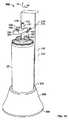
更に図9を参照すると、容器26は、当業者に知られている任意のサイズ及び容量を有するエアゾール容器とすることができる。但し、容器26は、上端24に圧着される取付カップ110を有する本体112(図13参照)を含むことが望ましい。取付カップ110は略円筒状であり、周囲に延出する外壁114を含む(図9参照)。台116は、取付カップ110から上方へ延出する。容器26内のバルブアセンブリ(図示せず)は、台116から上方へ延出するバルブステム118を含む。穴120はバルブアセンブリからバルブステム118まで延在する。バルブステム118は、Van der Heijdenの米国特許第4,064,782号に開示されるものと同様の、傾斜作動式タイプのバルブステムである。当該特許文献の全内容を参照によって本願明細書中に援用する。 Still referring to FIG. 9, the
バルブステム118の遠位端が十分に、すなわち操作可能な位置へ、半径方向に傾斜されると、バルブアセンブリが開放され、容器26の内容物がバルブステム118の放出端122から放出される。本願明細書中に使用される線対称座標系の用語において、半径方向変位は、バルブステム118の遠位端の、長手軸14から離間する方向への移動をも含む。従って、このような半径方向変位は、バルブステム118の遠位端の横方向移動として特徴付けられてもよい。容器26の内容物は連続的に放出されることもでき、あるいは定量放出されることもできる。更に、容器26の内容物の放出は、任意の方法にて実施できる。例えば、放出は一部定量で放出されてもよく、あるいは多数回にわたり連続して放出されてもよい。 When the distal end of the
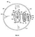
図8〜図12C参照すると、第一の横壁124は、互いに対向する側に第一及び第二のフレーム部材126及び128を備えている。第一及び第二のフレーム部材126及び128はプラットホーム86の頂部90に取り付けられている。第二の横壁130は、互いに対向する側から延出し、同様にプラットホーム86の頂部90に取り付けられている、第三及び第四のフレーム部材132及び134を備えている。第三及び第四の横壁140及び142は、ベース18の構造を補強すべく設けられる。 Referring to FIGS. 8 to 12C, the first
第一及び第二のフレーム部材126及び128は、1本以上の単3電池又は単4電池を含む直流電源144を保持すべく適合される。本実施形態の電源144は、他の電源との間にバッテリ互換性を示すべく概略的に示されている。諸実施形態において、バッテリは、導線146を有する再充電可能ニッケルカドミウム電池パックで置き換えられてもよい。導線146は図13に示すように交流電力コンセント148にバッテリーパックを接続すべく使用できる。別の実施形態では、直流電源144全体を、当業者に知られているような適切な電力変圧器及び交流/直流変換器を有する交流電源アダプタで置き換えることもできる。 The first and
図14及び図15には、振動モータが示され、当該振動モータは、駆動モータ150、駆動モータ150によって回転するシャフト154、及びシャフト154に偏心的に取り付けられる、重りをつけたヘッド152を含む。このような振動モータなどの作動機構はオーバーキャップ10の内側に設けられる。振動モータはエアゾール容器26からの液体の放出を発生させるべく適合されている。重りをつけたヘッド152が偏心回転すると、振動モータのダイナミックインバランスが生じ、これにより振動モータが、振動モータに取り付けられた部材を振動させる。構造及び/又は設計特性が異なる多くのタイプの振動モータを本実施形態と関連付けて使用できることが想定されている。但し、ハウジング12内に嵌合可能な程度に小型であると共に、バルブステム118を変位させるに足る力を発生しうる振動モータを使用することが有利であることがわかっている。代表的な振動モータとして、北米パナソニック株式会社(Panasonic Corporation of North America)から入手可能なパナソニック製振動モータ(機種番号:KHN6)が挙げられる。KHN6モータは重量1.15グラム、定格1.3ボルト及び70ミリアンペア、回転数7,000rpmであり、0.76ニュートン(0.17ポンド)の出力を発生する。14 and 15illustrate a vibration motor, which includes a
図8〜図12Cは、プリント基板162に配置される、通常は開放されているスイッチ160を示している。本実施形態では、プリント基板162は第二の横壁130の一部を含む。スイッチ160は、操作可能に押しボタンを手動で押下することにより開スイッチ160が閉止されるように、押しボタン34と位置合わせされている。更に、ユーザにより選択可能なスイッチアセンブリ164は、プリント基板162の頂部に隣接して配置される。ユーザにより選択可能なスイッチアセンブリ164は上方に延出するフィンガ166などの制御部材を含む。フィンガ166は異なる操作モード(以下に詳述する)を選択するために使用されてもよい。除去可能キャップ20がベース部18と係合すると、フィンガ166は、ユーザが操作によりフィンガ166と相互作用できるように、ノッチ74内に嵌合する(図1を参照)。ユーザにより選択可能なスイッチアセンブリ164は、本願明細書中に示されるような、フィンガ166によって制御される直線変位タイプのスイッチであってもよい。但し、ユーザにより選択可能なスイッチアセンブリは回転式であり、回転ノブにより制御可能であり、あるいは当該技術で知られている他の幾何学形状及び対応する制御機構を有していてもよい。更に、プリント基板162に配置された発光ダイオード(LED)168は、除去可能キャップ20の光透過性ロッド78に近接配置される(図9を参照)。 8-12C show a
図12A〜図12C、図16A及び図16Bを特に参照すると、ディスペンス部材170が示されている。本実施形態では、ディスペンス部材170は、放出端172及び下端174を有する円筒状部材を含む。ディスペンス部材の下端174に隣接する開口部178から放出端172を通じてボア176が延在している。ディスペンス部材170は、エアゾール容器26内のバルブアセンブリとディスペンス部材170の放出端172との間に連続流体連通を提供する。ディスペンス部材170は、圧入又は当業者に知られている他の方法によってバルブステム118に配置されてもよい。 With particular reference to FIGS. 12A-12C, 16A and 16B, a dispensing
ハウジング12がエアゾール容器26に配置されると、バルブステム118の遠位端は、ディスペンス部材170の下端174に隣接している開口部178内に着座する。ディスペンス部材170の放出端172は、ハウジング12の放出オリフィス66から垂下する円錐台形壁68に隣接して及び/又は円錐台形壁68内に配置される。ディスペンス部材170は、ディスペンス部材170の放出端172を放出オリフィス66と位置合わせすべく適宜中央に配置される。他の実施形態では、ディスペンス部材170は非円筒形状を有し、及び/又は部材170の全体又は一部の長さにわたりその寸法を変化させる。例えば、ボア176の放出端172は、ボア176の他の部分より狭くてもよく、あるいはボア176の他の部分に対し角度を付けられていてもよい。更に、バルブステム118及びディスペンス部材170の長さを各々延長するボア120及び176の全て又は一部は円筒状であってもよく、あるいは他の形状であってもよい。例えば、放出端172に隣接しているボア176の一部は正方形の断面を有していてもよく、ボア176の残りの部分は略円形の断面を有していてもよい。 When the
ディスペンス部材170がオーバーキャップ10に取り付けられてもよいことが更に想定されている。この性質の取付手段により、ユーザの取り扱い性が向上し、ディスペンス部材170の損失の防止を支援でき、一体型のオーバーキャップ10に更なる利点を提供する。オーバーキャップ10にディスペンス部材170を接続する取付手段を有することの更なる利点として、ディスペンス部材170がガイド機能を備えることができる点が挙げられる。すなわち、オーバーキャップ10がエアゾール容器26に配置されるか、除去可能キャップ20がベース部18に配置されることで、ディスペンス部材170はバルブステム118と相互作用し、オーバーキャップ10及び/又は除去可能キャップ20を操作可能な位置へ向ける。あるいは、又はこれに加えて、エアゾール容器26にオーバーキャップ10を配置し、又はベース部18上に除去可能キャップ20を配置することにより、ディスペンス部材170のバルブステム118との係合を案内すべく位置合わせする機能が提供される。一実施形態において、ディスペンス部材170の下端174は、第一、第二、第三又は第四の横壁124、130、140、142の1つ以上に柔軟に取り付けられる。図9、図11、図16A及び16Bに示されるように、非伸張状態における弾性ストリップ179により、ディスペンス部材170が横壁124及び130に取り付けられる。図6及び図11は、ディスペンス部材170が別の弾性ストリップ179によって横壁142に取り付けられていることを示す。弾性ストリップ179は、オーバーキャップ10に固定された状態にディスペンス部材170を保持するに足る強度を有する。しかし、弾性ストリップ179は、振動モータにより駆動されると、ディスペンス部材170の動的反応に対する干渉を最小限とするように、ディスペンス部材170に取り付けられている。ディスペンス部材170は、通常の技術を有する当業者には知られている他の方法によってオーバーキャップ10に取り付けられてもよい。It is further envisioned that the dispensing
本実施形態では、振動モータは、バルブステム118と振動連通するようにディスペンス部材170に取り付けられている。すなわち、振動モータは、振動モータの振動動作が直接的又は間接的にバルブステム118を変位させるように、オーバーキャップ10内に設けられる。駆動モータ150は、ディスペンス部材170に直接接続されてもよいし、結合部材180を介してディスペンス部材170に接続されてもよい。結合部材180は、圧入、接着又は当業者に知られている他の方法によってディスペンス部材170に取り付けられてもよい。同様に、駆動モータ150は、圧入、接着又は当業者に知られている他の方法によって結合部材180に取り付けられてもよい。別の実施形態では、駆動モータ150は結合部材180を介してバルブステム118に接続されてもよい。他にも多数の接続構成が可能であることが想定されている。例えば、駆動モータ150はバルブステム118に直接接続されてもよく、あるいはバルブステム118と振動連通する別の構造に取り付けられてもよい。プリント基板162はワイヤ182により駆動モータ150に接続される。In the present embodiment, the vibrationmotor is mounted on the dispensing
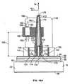
駆動モータ150の非作動時には、ディスペンス部材172は長手軸14と位置合わせされている。振動モータが振動すると、バルブステム118へトルク量を供給すべくモーメントアームを通じて作用する力が発生する。これによりバルブステム118が作動され、エアゾール容器26の内容物を放出する。図8、図10、図11及び図16Aに示されるように、駆動モータ150は長手軸14から距離184だけオフセットされたディスペンス部材170に取り付けられる。図8、図10、図12A及び図16Aに示されるように、シャフト154の回転軸186は長手軸14と平行の向きとされる。振動モータはディスペンス部材170の略中央近傍に取り付けられてもよい。あるいは、振動モータは、ディスペンス部材170の下端174又は放出端172の近傍、あるいはこれらの端部の間の任意の位置に取り付けられてもよい。距離185は、図9、図16A及び図16Bに示されるように振動モータの取付点と、傾斜作動式バルブステム118のベースとの間で測定され、好ましくは約0.25インチ〜約2インチの範囲である。更に、距離184は、好ましくは約0.25インチ〜約1インチの範囲である。モーメントアームの有効長は、長さ184及び185と、振動モータの向きとの幾何学的組合せによって決定される。例えば、振動モータをディスペンス部材170の放出端172の近傍に取り付けることにより、振動モータによって発生された力をバルブステム118に伝えるためのモーメントアームが長くなる。モーメントアームの有効長は、傾斜作動式バルブステム118のベースに作用するトルク量、従ってエアゾール容器26の内容物の噴射率を決定する一要素である。During non-operation of the
しかし、駆動モータ150は、シャフト154の回転軸186が任意の向きにある状態でディスペンス部材170に取り付けられてもよい。例えば、駆動モータ150は、図12Bに示されるように、シャフト154の回転軸186が長手軸14に対し45度の角度をなすように、ディスペンス部材170に取り付けられてもよい。また、駆動モータ150は、図12Cに示されるように、シャフト154の回転軸186が長手軸14に対して略直交するようにディスペンス部材170に取り付けられてもよい。実際は、駆動モータ150は、シャフト154の回転軸186が長手軸14に対し任意の角度をなしてディスペンス部材170に取り付けられることができる。However,drive
更に、振動モータは、シャフト154の回転軸186が長手軸14と同一平面上にあるが平行ではないように、ディスペンス部材170に取り付けられてもよい。例えば、振動モータは、図16Bに破線で表された第一の位置188によって示されるように、シャフト154の回転軸186が長手軸14との間に45度の角度をなして同一平面上となるように、ディスペンス部材170に取り付けられてもよい。例えば、振動モータは、図16Bに破線で表された第二の位置190によって示されるように、シャフト154の回転軸186が長手軸14との間に90度の角度をなして同一平面上となるようにディスペンス部材170に取り付けられてもよい。Furthermore, the vibrationmotor, the
更に、振動モータが、シャフト154の回転軸186と長手軸14との間で測定される角度が0度〜90度の間の任意の角度、例えば15度、30度、60度、75度であるように、ディスペンス部材170に取り付けられてもよいことが想定されている。実際、振動モータは、ディスペンス部材170に半径方向の振動変位を付与する上で有利とされる、長手軸14と回転軸186の間の他の相対的な向き又は向きの組合せでディスペンス部材170に取り付けられてもよい。Furthermore, the vibrationmotor is any angle between the angle of 0 degrees to 90 degrees measured between the
ディスペンス部材170は、作動されると、振動モータにより発生される力に応じて半径方向に振動変位し、半径方向の振動変位が起こる度にバルブステム118が作動する。ディスペンス部材170の変位頻度は、例えば、振動モータのオフセット距離184、振動モータの取付距離185、振動モータの向き、振動モータにより発生される力、ディスペンス部材170及びバルブステム118の物理的特性を含む多数の要素に依存する。上述の代表的な振動モータの回転数7000rpmでは、振動変位は比較的高速で起こり、人には連続スプレーとして認識される。上記要素の1つ以上を変更することによりバルブステム118のディスペンス速度を変更できることが想定されている。例えば、製造中に、振動モータはバルブステム118から離間されたあるいは接近した距離184に配置されてもよく、ディスペンス部材170の放出端172又は下端174に接近して取り付けられてもよく、あるいは付加的な力を発生する別の振動モータと置き換えられてもよい。更に、ディスペンス部材170及び/又はバルブステム118により大きい動的反応を付与するため、弾力が高い又は低い別の材料を使用することもできる。別の例として、振動モータは定格電圧より僅かに高いもしくは低いいくつかの電圧レベルにおいてそれぞれ駆動されてもよい。各電圧レベルは振動モータに異なるレベルの力を発生させる。これらの力はバルブステム118のディスペンス速度に対応する。スイッチアセンブリ164に加えて、あるいはスイッチアセンブリ164の一部として、オーバーキャップ10にスイッチ機構が設けられてもよい。スイッチ機構はユーザが電圧レベルを選択し、従ってバルブステム118のディスペンス速度を選択することを可能とする。
更に、バルブステム118に振動動作を付与すべく使用される作動機構は、振動モータ以外の機構であってもよいことが想定されている。作動機構の一例として、ディスペンス部材170の外側面に接する回転カムが挙げられる。カムは駆動トランスミッションを介して小型モータによって駆動される。駆動トランスミッションはカムの回転を正確に制御し、これによりカムはディスペンス部材の振動変位を発生させるべく高速で繰り返し回転することができ、あるいはディスペンス部材を正確に変位させるように僅かな回転を与えるべく小さく回転することができる。作動機構の別の例として、磁気ディスペンス部材の近傍に配置される電磁石が挙げられる。電磁石が作動される度に、磁気ディスペンス部材と相互作用する磁界が発生し、磁気ディスペンス部材を半径方向に変位させる。電磁石が作動される度に発生される力の量、及び電磁石の作動頻度は、単純な回路類及び当業者に知られているような可変制御装置によって便宜に合わせ容易に制御できる。作動機構の更に別の例として、高周波音を発生する電子オシレータ回路が挙げられる。電子オシレータ回路は、電子オシレータ回路からの音をディスペンス部材170の表面へ向かわせるべくオーバーキャップに配置されてもよい。ディスペンス部材170は、音に動的反応を示す材料、すなわち定在波パターンにさらされた際に振動を示す材料で作製できる。傾斜作動式バルブステム118を作動するための更に別の作動機構も可能であり、有用である。例えば2007年5月10日出願の米国特許出願番号第11/801,557号に記載された作動機構のうちのいずれかを、バルブステム118に振動動作を付与すべく変更できる。当該特許出願の全開示内容を参照によって本願明細書中に援用する。Additionally, actuation mechanism used to impart the oscillatory motion to the
ディスペンス部材170は、バルブステム118の半径方向の振動変位を含む所定の期間、すなわちスプレー期間にわたり、繰り返し半径方向に放出位置まで変位されることが望ましい。通常、スプレー期間は約170ミリ秒間継続してもよい。実際は、所望により、ディスペンス部材170は、容器内容物が枯渇するまで繰り返し半径方向に放出位置まで変位されてもよい。更に、ディスペンス部材170は、単一の作動信号の発生に応じて複数のスプレー期間にわたり繰り返し半径方向に移動されてもよい。スプレー期間はレスト期間により区分される。容器からの単一のスプレー期間を延長することが望ましくない場合、あるいは間欠放出が望まれる場合、多数のスプレー期間が存在することは有益となりうる。 The dispensing
上述のごとくバルブステム118は各半径方向の振動変位により作動される。発振の全サイクルは、ディスペンス部材170の放出端172(又はバルブステム118)の第一の径方向における第一の最大偏位への移動、及びこれに続く第二の径方向における第二の最大偏位への動作を含む。第二の径方向は第一の径方向と正反対であってもよいし、そうでなくてもよい。第一の発振周期の後、バルブステム118及びディスペンス部材170が非作動位置へ戻る前に1つ以上の後続の発振周期が存在してもよい。従って、ディスペンス部材170の放出端172の振動変位の各全サイクルは、2点において最大半径方向変位を行う。バルブステム118が製品を放出する、放出端172の振動変位のサイクルに沿った任意の点を作動位置とみなすことができる。ディスペンス部材170が上記代表的な振動モータの回転速度に概ね相当する発振周波数に到達すると仮定すると、ディスペンス部材170の発振周波数は約7,000Hzに達する。一実施形態では、ディスペンス部材170によって到達可能な発振周波数の範囲は約1,000Hz〜約10,000Hzである。従って、ディスペンス部材の発振サイクルの期間は、約1ミリ秒〜約0.1ミリ秒の間で変化する。 As described above, the
図17は、使用状態におけるオーバーキャップ10の動作を示すタイミング図である。まず、スイッチアセンブリ164のフィンガ166が「OFF」位置から4つの操作モード192、194、196及び198のうちの1つに移動されることによりオーバーキャップ10が作動される。次いで、制御回路(図示せず)がオーバーキャップ10を起動時遅延期間内とする。制御回路はプリント基板162にエッチングされていてもよい。4つの操作モード192、194、196、198の各々は、連続するスプレー期間の間の所定のスリープ期間に相当する。例えば、第一の操作モード192は5分間のスリープ期間に相当してもよく、第二の操作モード194は7.5分間のスリープ期間に相当してもよく、第三の操作モード196は15分間のスリープ期間に相当してもよく、第四の操作モード198は30分間のスリープ期間に相当してもよい。ここでは、第一の操作モード192が選択されたと仮定する。起動時遅延期間が満了すると、振動モータが作動され、第一のスプレー期間においてオーバーキャップ10から液体を放出する。好適な起動時遅延期間は約3秒間である。また、スプレー期間は通常約170ミリ秒間である。第一のスプレー期間が満了すると、オーバーキャップ10は、5分間の第一のスリープ期間に入る。第一のスリープ期間が満了すると、振動モータが作動され、第二のスプレー期間において液体を放出する。次いで、オーバーキャップ10は、5分間の第二のスリープ期間に入る。この例では、第二のスリープ期間はオーバーキャップ10が手動で作動されることにより中断される。液体は第三のスプレー期間にディスペンスされる。その後、スリープ期間とスプレー期間を交互に継続する自動運転が行われる。スリープ期間における任意の時点で、ユーザは押しボタン34を押下することにより選択可能な期間あるいは固定期間にわたりオーバーキャップ10を手動で作動させることができる。手動によるスプレー作業が終了すると、オーバーキャップ10は残りのスリープ期間を完了する。その後、スプレー作業が実施される。FIG. 17 is a timing chart showing the operation of the
別の実施形態では、スイッチアセンブリ164は上記4つの個別の操作モード192、194、196、198に代えて連続した設定範囲を有していてもよい。このような実施形態では、スイッチアセンブリ164は、ダイヤル(図示せず)などのスイッチ機構を備えてもよい。スイッチ機構は、数時間又は数日間継続する連続するスプレー及び期間の間の、スプレー期間及び/又はスリープ期間の連続的なバリエーションをユーザに提供する。更に別の実施形態では、スイッチアセンブリ164は光電池光センサで置き換えられてもよく、及び/又は光電池光センサによりスイッチアセンブリ164を補ってもよい。光電池光センサは動作検出器として使用できる。パッシブ赤外線動作センサ又はピロ電気的動作センサ、赤外反射動作センサ、超音波動作センサ、レーダー又はマイクロ波による無線動作センサなどの、当業者に知られている他の動作検出器も利用できる。光電池は周辺光を集光し、これにより制御回路が光強度の変化を検出することが可能となる。光電池出力のフィルタリングは制御回路によって行われる。制御回路が閾値光条件に到達したと判断すると、すなわち例えば所定レベルの光強度変化が発生したことと判断すると、制御回路は振動モータを作動するための信号を生成する。例えば、オーバーキャップ10が明かりのついたバスルームに設置される場合、センサの前を通過する人がセンサに到達する十分な量の周辺光を遮断し、これにより制御回路が振動モータを作動させ、液体を放出させる。In another embodiment, the
更に、スイッチアセンブリ164は、振動センサ、臭気センサ、熱感知器又は当業者に知られている他のセンサと置き換えられてもよく、あるいはこれを補うものであってもよいことが想定されている。あるいは、スイッチアセンブリ164の代わりに、あるいはスイッチアセンブリ164と組み合わされて1つ以上のセンサがオーバーキャップに設けられてもよい。当業者は、単独の又はスイッチアセンブリ164と組み合わされた任意のタイプのセンサを提供でき、及び/又はユーザの要求を満たす他のセンサを提供できることが想定されている。ある実施形態において、スイッチアセンブリ164とセンサとが同一のオーバーキャップ内に設けられる。このような実施形態では、ユーザは、オーバーキャップ10の振動モータを自動的に操作すべくタイマベースのスイッチアセンブリ164を使用することを選択してもよい。又は、ユーザは、オーバーキャップ10を作動させる前に所与の事象を検出すべくセンサを使用することを選択してもよい。あるいは、オーバーキャップ10は、タイマベース及びセンサベースの運転モードで同時に運転してもよい。Further, it is envisioned that the
オーバーキャップ10が作動状態にあるとき、LED168は光透過性ロッド78を照射する。スリープ期間中、LED168は15秒に1回断続的に明滅する。選択された操作モードに応じて、スプレー期間が近づくと、LED168の明滅回数が増大し始める。LED168による頻繁な照射は、オーバーキャップ10が流体内容物が空気中へ放出しようとしていることを視覚的に表示する。 When the
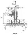
図18に表された別の実施形態では、エアゾール容器26はフレーム302を有するデバイス300内に配置される。フレーム302はベース部304及びテーパ状円筒壁306を含む。凹部308はベース部304内に設けられ、エアゾール容器26を受容すべく適合される。カラム310はベース部304と一体形成されると共に、ベース部304から上方へ延出する。カラム310はエアゾール容器26の最大長手方向寸法を越えて延出する。エアゾール容器26をカラム310から一定距離離間させて配置するため、フィンガ312がカラム310から延出している。振動モータは結合部材180によってディスペンス部材170に取り付けられている。ワイヤ182は、カラム310の前壁316のアパーチャ314を通って延出する。回路基板(図示せず)などの電子機器及び電源(図示せず)はカラム310内に収容される。本願明細書中に記載した任意の操作シーケンス又は方法論を含む操作シーケンスにおいて、フレーム302内の制御回路(図示せず)は、経時タイマ、センサ入力又は手動による作動に応答して電気信号を生成する。信号により振動モータが起動され、ディスペンス部材170に半径方向の振動力が加わる。上述のごとく、ディスペンス部材170に十分な半径方向の力が加わると、バルブステム118が半径方向に変位する。他の実施形態では、フレーム302は、エアゾール容器26を完全に包含する、より大きいハウジング(図示せず)の一部をなしてもよい。このようなハウジングはディスペンス部材170の放出端172と略位置合わせされる放出オリフィスを含む。ハウジングは、床や棚などの水平面上へ自立して設置されてもよいし、あるいは壁又は支持柱などの垂直面に取り付けられてもよい。In another embodiment represented in FIG. 18, the
本願明細書中に記載された実施形態はいずれも他の実施形態に関連して開示された任意の構造や方法論を含むように変更できる。更に、本発明は例示されたタイプのエアゾール容器に制限されない。また、本願明細書中に開示された実施形態のうちの任意のオーバーキャップを、傾斜作動式バルブステムを有する任意のタイプの流体容器と組み合わされて使用されるように変更できる。 Any of the embodiments described herein can be modified to include any structure or methodology disclosed in connection with other embodiments. Further, the present invention is not limited to the illustrated types of aerosol containers. Also, any of the overcaps of the embodiments disclosed herein can be modified to be used in combination with any type of fluid container having a tilt-actuated valve stem.
エアゾールディスペンサは、一般的に、エアゾール容器内に保管されるエアフレッシュナ、脱臭剤、殺虫剤、殺菌剤、充血除去薬、芳香などの揮発性物質をディスペンスするために使用される。エアゾール容器の自動バルブ作動システムにより、人間と相互作用することなくエアゾール容器の内容物が所定のタイムスケジュールに従って放出できる。一般的に、エアゾール容器リリースバルブ用の、傾斜作動式バルブステムは、垂直方向に作動されるバルブステムと比べ、作動に要する力が小さくてすむ。傾斜作動式バルブステムを振動モータにより自動的に作動するためのシステムが提示される。このシステムは、通常の、傾斜作動式エアゾール容器と共に使用されるように一般的なオーバーキャップ内に設置されることができ、これによりエアゾール容器の有用性が向上する。 Aerosol dispensers are commonly used to dispense volatile substances such as air fresheners, deodorizers, insecticides, bactericides, decongestants, aromas, etc. stored in aerosol containers. The aerosol container automatic valve actuation system allows the contents of the aerosol container to be released according to a predetermined time schedule without interacting with humans. In general, a tilt-actuated valve stem for an aerosol container release valve requires less force to operate than a vertically actuated valve stem. A system for automatically operating a tilt-actuated valve stem with a vibration motor is presented. The system can be installed in a typical overcap for use with a conventional, tilt-actuated aerosol container, which improves the utility of the aerosol container.
上記説明を考慮すれば、当業者には本発明に対する多数の変更が明らかとなる。従って、説明はあくまで例示目的で行われたものであり、当業者が本発明を実施及び使用できるようにし、本発明を実施するための最良の形態を教示すべく提示されたものであることを認識されたい。添付の特許請求の範囲に含まれるあらゆる変更に対し独占的権利が付与されている。 Many modifications to the present invention will become apparent to those skilled in the art in view of the above description. Accordingly, the description is given for illustrative purposes only and is presented to enable one of ordinary skill in the art to make and use the invention and to teach the best mode for carrying out the invention. I want to be recognized. Exclusive rights are granted for any changes that come within the scope of the appended claims.
関連出願への相互参照
適用なしCross-reference to related applications
連邦政府資金援助研究開発に関する参照
適用なしReference to federal funding research and development Not applicable
シーケンシャルリスト
適用なしSequential list Not applicable
Claims (18)
Translated fromJapanese前記バルブステムと連通する振動モータと、
を含み、
前記振動モータは、作動されると前記バルブステムに半径方向運動を付与すべく適合され、
前記振動モータは、前記バルブステムに配置されたディスペンス部材に取り付けられ、前記ディスペンス部材は前記バルブステムと流体連通し、
前記振動モータは結合部材によって前記ディスペンス部材に取り付けられ、
前記振動モータは、駆動モータと、前記駆動モータによって回転するシャフトと、前記シャフトに偏心的に取り付けられる、重りをつけたヘッドと、を含み、
前記駆動モータは、前記結合部材に固定され、前記結合部材は、前記ディスペンス部材に固定されている
ことを特徴とするディスペンスシステム。A tilt-actuated valve stem operably connected to the vessel valve;
A vibration motor in communication with the valve stem;
Including
The vibration motor is adapted to impart radial motion to the valve stem when actuated;
The vibration motor is attached to a dispense member disposed on the valve stem, the dispense member in fluid communication with the valve stem,
The vibration motor is attached tothe dispensing member by a coupling member;
The vibration motor includes a drive motor, a shaft rotated by the drive motor, and a weighted head that is eccentrically attached to the shaft.
The drive motor is fixed to the coupling member, and the coupling member is fixed to the dispensing member.
Dispensing systemcharacterized by that .
前記シャフトの回転軸は、前記円筒部材の軸と交差する The axis of rotation of the shaft intersects the axis of the cylindrical member
ことを特徴とする請求項1〜4の何れか1項に記載のディスペンスシステム。 The dispensing system according to any one of claims 1 to 4, wherein:
を含む、
揮発性物質容器用オーバーキャップ。The dispensing system according to any one of claims 1 to 7, a housingfor housing thedispensing system,
Theincluding,
Volatile substance container overcap.
請求項8〜13の何れか1項に記載のオーバーキャップ。Before Symbol vibration motor timer is actuated in response to at least from one of signals of the sensors or manual actuating device is adapted to impart radialmovement to the valve stem,
The overcap according to any one of claims 8 to 13 .
Applications Claiming Priority (3)
| Application Number | Priority Date | Filing Date | Title |
|---|---|---|---|
| US11/893,456 | 2007-08-16 | ||
| US11/893,456US8381951B2 (en) | 2007-08-16 | 2007-08-16 | Overcap for a spray device |
| PCT/US2008/009661WO2009023208A1 (en) | 2007-08-16 | 2008-08-13 | Tilt-activated valve stem actuator |
Publications (2)
| Publication Number | Publication Date |
|---|---|
| JP2010537895A JP2010537895A (en) | 2010-12-09 |
| JP5221658B2true JP5221658B2 (en) | 2013-06-26 |
Family
ID=39876793
Family Applications (1)
| Application Number | Title | Priority Date | Filing Date |
|---|---|---|---|
| JP2010521015AExpired - Fee RelatedJP5221658B2 (en) | 2007-08-16 | 2008-08-13 | Inclined valve stem actuator |
Country Status (10)
| Country | Link |
|---|---|
| US (1) | US8381951B2 (en) |
| EP (2) | EP2311754A3 (en) |
| JP (1) | JP5221658B2 (en) |
| KR (1) | KR20100057623A (en) |
| CN (1) | CN101827762A (en) |
| AR (1) | AR067958A1 (en) |
| AU (1) | AU2008287364B2 (en) |
| BR (1) | BRPI0815495A2 (en) |
| CA (1) | CA2695992A1 (en) |
| WO (1) | WO2009023208A1 (en) |
Families Citing this family (14)
| Publication number | Priority date | Publication date | Assignee | Title |
|---|---|---|---|---|
| US8387827B2 (en)* | 2008-03-24 | 2013-03-05 | S.C. Johnson & Son, Inc. | Volatile material dispenser |
| US9527656B2 (en)* | 2009-07-31 | 2016-12-27 | Seaquistperfect Dispensing L.L.C. | Touchless dispenser |
| WO2013043684A2 (en) | 2011-09-19 | 2013-03-28 | S. C. Johnson & Son, Inc. | Spray dispenser |
| US8622259B2 (en)* | 2012-04-09 | 2014-01-07 | Hsu-Hui Chang | Electrical valve control device |
| US9108782B2 (en) | 2012-10-15 | 2015-08-18 | S.C. Johnson & Son, Inc. | Dispensing systems with improved sensing capabilities |
| USD821203S1 (en) | 2015-09-21 | 2018-06-26 | S. C. Johnson & Son, Inc. | Container with cap and base |
| USD858288S1 (en) | 2015-09-21 | 2019-09-03 | S. C. Johnson & Son, Inc. | Container with base |
| USD821201S1 (en) | 2015-09-21 | 2018-06-26 | S. C. Johnson & Son, Inc. | Container with base |
| USD821202S1 (en) | 2015-09-21 | 2018-06-26 | S. C. Johnson & Son, Inc. | Container with cap and base |
| USD830827S1 (en) | 2015-09-21 | 2018-10-16 | S. C. Johnson & Son, Inc. | Container with base |
| JP2017149125A (en)* | 2016-02-27 | 2017-08-31 | 俊寛 倉見 | Finger tip humidifier |
| CA184784S (en)* | 2018-05-24 | 2019-12-30 | Zobele Holding Spa | Diffusing evaporator of active substances |
| US20220096687A1 (en)* | 2020-09-29 | 2022-03-31 | Tabitha Angel Bryant | Sanitizer Aerosol Dispensing Apparatus |
| US20220331826A1 (en)* | 2021-04-16 | 2022-10-20 | Janarthan Gnanachandran | Spraying Device |
Family Cites Families (316)
| Publication number | Priority date | Publication date | Assignee | Title |
|---|---|---|---|---|
| US3127060A (en) | 1964-03-31 | Automatic actuator for spray containers | ||
| US3273610A (en) | 1966-09-20 | Valved pressurized fluid dispensing receptaclewith receptacle-attached fitting | ||
| US2608319A (en) | 1948-01-15 | 1952-08-26 | Stanton H Petry | Gas discharge device for gas bombs |
| US2613108A (en) | 1949-04-01 | 1952-10-07 | George F Kraus | Fluid dispenser |
| US2928573A (en) | 1958-02-25 | 1960-03-15 | Syncro Mist Controls Inc | Valve actuating assembly for metered spray atomizing devices |
| US3018056A (en) | 1960-09-29 | 1962-01-23 | Montgomery Mfg Company Inc | Timed spray dispensers |
| US3165238A (en) | 1962-02-19 | 1965-01-12 | Heuer Timer Corp | Intermittent actuating device for dispensers |
| GB1033025A (en) | 1962-02-19 | 1966-06-15 | Heuer Timer Corp | Intermittent valve-actuating device for portable pressurised aerosol dispensers |
| US3185356A (en) | 1962-03-27 | 1965-05-25 | Risdon Mfg Co | Metering valve |
| US3198394A (en)* | 1962-11-16 | 1965-08-03 | Lefer Samuel | Pressurized dispensers |
| US3115277A (en) | 1963-01-22 | 1963-12-24 | Jr Charles A Montague | Pressure can device |
| US3199732A (en) | 1963-03-20 | 1965-08-10 | Robertshaw Controls Co | Spray timer |
| US3289886A (en) | 1964-02-24 | 1966-12-06 | Goldsholl Morton | Timing device and method |
| US3228609A (en) | 1964-05-26 | 1966-01-11 | Syncro Mist Controls Inc | Spray dispenser |
| US3180532A (en) | 1964-06-18 | 1965-04-27 | Clayton Corp Of Delaware | Tamper-proof cover for a container |
| US3269602A (en) | 1964-09-24 | 1966-08-30 | Time Mist Inc | Periodically operated aerosol dispenser |
| US3240389A (en)* | 1964-12-24 | 1966-03-15 | Robertshaw Controls Co | Spray timer |
| US3329314A (en) | 1965-08-20 | 1967-07-04 | Gen Time Corp | Timed actuating device for aerosol dispenser |
| US3305134A (en) | 1965-10-21 | 1967-02-21 | Union Carbide Corp | Automatic spray device |
| US3368717A (en) | 1965-10-24 | 1968-02-13 | Time Mist Inc | Dispenser |
| US3326418A (en) | 1966-01-21 | 1967-06-20 | Willis A Kropp | Dispensing device |
| US3398864A (en) | 1966-06-24 | 1968-08-27 | Gen Time Corp | Adapter apparatus for automatic aerosol dispenser |
| US3455485A (en) | 1967-03-20 | 1969-07-15 | Lawrence T Crownover | Automatic cycling mechanism |
| US3419189A (en) | 1967-08-21 | 1968-12-31 | Iketani Taisho | Device for automatically and intermittently spraying pressurized products |
| US3411670A (en) | 1967-09-11 | 1968-11-19 | Edward L Brown | Automatic dispenser for pressurized liquid |
| US3497108A (en) | 1967-10-26 | 1970-02-24 | Dart Ind Inc | Automatic dispenser |
| US3543122A (en) | 1968-01-02 | 1970-11-24 | Air Guard Control Canada Ltd | Automatic aerosol dispenser |
| US3477613A (en) | 1968-02-29 | 1969-11-11 | Dart Ind Inc | Aerosol dispenser actuated by propellant pressure |
| US3497110A (en) | 1968-04-12 | 1970-02-24 | Eversharp Inc | Aerosol dispenser |
| US3591058A (en) | 1968-11-05 | 1971-07-06 | Republic Corp | Tapping device for beer kegs and the like |
| US3542248A (en) | 1969-01-08 | 1970-11-24 | John J Mangel | Aerosol dispenser controlled by permanent magnet |
| US3690519A (en) | 1969-01-24 | 1972-09-12 | Victor Wassilieff | Closures for containers |
| US3589562A (en) | 1969-02-10 | 1971-06-29 | Buck Willard | Pressure-powered aerosol timer |
| US3664548A (en) | 1969-07-10 | 1972-05-23 | Inst For Ind Res & Standards | Aerosol containers and valves thereof |
| US3620023A (en) | 1969-07-25 | 1971-11-16 | Howard C Schmid | Pulsating valves |
| BE754629A (en) | 1969-08-11 | 1971-01-18 | Gen Time Corp | AUTOMATIC AEROSOL DISPENSER OPERATING FOR LONG PERIODS |
| US3617214A (en) | 1969-08-18 | 1971-11-02 | Raymond E Dolac | Door-operated air freshener |
| US3627176A (en) | 1969-09-24 | 1971-12-14 | William M Sailors | Automatic spray dispenser for pressurized fluid |
| US3584766A (en) | 1969-12-10 | 1971-06-15 | Charles M Hart | Spray dispenser having a capacitor discharge timer |
| US3643836A (en) | 1969-12-18 | 1972-02-22 | William Grayson Hunt | Programmed timer device and dispensing apparatus incorporating same |
| US3658294A (en)* | 1970-02-16 | 1972-04-25 | Ronald F Ewald | Tilt valve |
| US3677441A (en) | 1970-09-10 | 1972-07-18 | Virginia Chemicals Inc | Multiple aerosol dispenser |
| US3658209A (en) | 1970-10-29 | 1972-04-25 | Gen Time Corp | Automatic cycling discharging device |
| US3666144A (en) | 1970-12-11 | 1972-05-30 | Air Guard Control Canada Ltd | Aerosol dispensing apparatus having disc-shaped solenoid-actuated plunger |
| US3632020A (en) | 1970-12-17 | 1972-01-04 | Virginia Chemicals Inc | Dispenser for aerosol bombs |
| US3722749A (en) | 1970-12-31 | 1973-03-27 | M Ishida | Aerosol spray container |
| US3756465A (en) | 1971-01-06 | 1973-09-04 | P Meshberg | Automatic periodic dispenser |
| US3732509A (en) | 1971-01-18 | 1973-05-08 | Syncro Mist Controls Inc | Apparatus to provide periodic movement |
| US3726437A (en) | 1971-01-21 | 1973-04-10 | N Siegel | Aerosol spray dispenser |
| US3817429A (en) | 1971-02-24 | 1974-06-18 | T Smrt | Actuator for aerosol can valve |
| US3739944A (en) | 1972-05-25 | 1973-06-19 | Westinghouse Electric Corp | Automatic periodically actuated spray dispenser |
| US3870274A (en) | 1972-06-30 | 1975-03-11 | Chr Nielsens Eftf As | Motor driven valve |
| US3794216A (en) | 1973-02-22 | 1974-02-26 | Spray A Matic Prod Inc | Pressure powered aerosol timer |
| USRE29117E (en)* | 1973-07-16 | 1977-01-18 | Automatic spray dispenser with integrated test apparatus | |
| US4004550A (en) | 1973-11-29 | 1977-01-25 | White Ronald D | Apparatus for preparing microscope slides |
| US3929259A (en) | 1974-06-04 | 1975-12-30 | Charles R Fegley | Chemical dispensing anti-burglar device |
| US3885712A (en) | 1974-06-28 | 1975-05-27 | Sidney M Libit | Childproof closures of the pull-push type |
| US4077542A (en) | 1974-12-02 | 1978-03-07 | Petterson Tor H | Unattended aerosol dispenser |
| US3974941A (en) | 1974-12-16 | 1976-08-17 | Mettler Leo L | Automated aerosol mist dispenser |
| US3952916A (en) | 1975-01-06 | 1976-04-27 | Warner-Lambert Company | Automatic dispenser for periodically actuating an aerosol container |
| US3980205A (en) | 1975-03-20 | 1976-09-14 | Qantas Airways Limited | Aerosol can discharging apparatus |
| US4006844A (en) | 1975-04-10 | 1977-02-08 | The Risdon Manufacturing Company | Apparatus for operating an aerosol container |
| US4064573A (en) | 1975-07-02 | 1977-12-27 | Cahill, Sutton & Thomas | Cleanser-sanitizer and timed cycle deodorizing spray attachment for toilets |
| US3968905A (en) | 1975-08-07 | 1976-07-13 | Continental Can Company, Inc. | Time release aerosol dispenser |
| US4064782A (en) | 1976-05-06 | 1977-12-27 | Daniel Laflamme | Electronic music display device |
| US4068780A (en) | 1976-06-03 | 1978-01-17 | Fegley Charles R | Electrothermally actuated fluid dispensing device |
| US4068575A (en) | 1976-08-24 | 1978-01-17 | Whirlpool Corporation | Refuse compactor with selective spray device |
| US4063664A (en) | 1976-09-13 | 1977-12-20 | The Risdon Manufacturing Company | Device for indicating when automatic, periodic operation has emptied an aerosol container |
| GB1599153A (en) | 1976-10-12 | 1981-09-30 | Strattwell Developments Ltd | Fluid dispenser |
| IN148848B (en) | 1977-03-02 | 1981-06-27 | Abplanalp Robert H | |
| US4096974A (en) | 1977-03-11 | 1978-06-27 | Haber Terry M | Cover assembly for spray cans |
| AR211172A1 (en) | 1977-03-30 | 1977-10-31 | L E Freyre | A DEVICE FOR AUTOMATICALLY AND CONTROLLED EXPANDING AN AROMATIZING SUBSTANCE. |
| US4133408A (en) | 1977-10-27 | 1979-01-09 | General Motors Corporation | Flow amplifier valve assembly |
| BE866392A (en) | 1978-04-26 | 1978-08-14 | Staar Sa | SPRAY DEVICE FOR THE DIFFUSION OF LIQUIDS |
| US4275821A (en) | 1979-09-17 | 1981-06-30 | Lanno Joseph P | Drive system and fluid dispenser unit utilizing same |
| GR65081B (en) | 1980-04-19 | 1980-06-28 | Houstoulakis Nikitas | Apparatus for evaporation of insecticidal,deodorants a.t.c materials in planned times |
| ES256473Y (en) | 1981-02-26 | 1982-04-01 | AN PERFECTED DEVICE FOR AUTOMATICALLY DISPENSING LIQUID OR GASEOUS PRODUCTS CONTAINED IN A CONTAINER UNDER PRESSURE | |
| US4544086A (en) | 1982-11-19 | 1985-10-01 | Cook International, Inc. | Ornament including automatic and adjustable valving mechanism |
| US5012961A (en) | 1983-12-09 | 1991-05-07 | Milliken Research Corporation | Method of dispensing vapor to the air in a room and an apparatus for carrying out the method |
| DK8305664A (en) | 1983-12-09 | 1985-06-10 | ||
| US5029729A (en) | 1983-12-09 | 1991-07-09 | Milliken Denmark A/S | Method of dispensing vapor to the air in a room and an apparatus for carrying out the method |
| DE3627222A1 (en) | 1986-08-11 | 1988-02-18 | Siemens Ag | ULTRASONIC POCKET SPRAYER |
| ZA885235B (en) | 1987-08-28 | 1989-04-26 | Andris Raimund | Metering and spray pump |
| FR2637512B1 (en) | 1988-10-07 | 1991-03-29 | Lvmh Rech | DEVICE FOR AUTOMATIC DELIVERY OF ANY PRODUCT OR OBJECT |
| US4989755A (en) | 1988-12-20 | 1991-02-05 | Shiau Guey Chuan | Automatic cleaning-liquid dispensing device |
| US5098291A (en) | 1989-04-14 | 1992-03-24 | Colgate-Palmolive Company | Pressurized medicant applicator |
| US4967935A (en) | 1989-05-15 | 1990-11-06 | Celest Salvatore A | Electronically controlled fluid dispenser |
| ES2043306T3 (en) | 1989-05-31 | 1993-12-16 | Conceptair Anstalt | PROCEDURE AND ELECTRICAL, ELECTRONIC AND MECHANICAL DEVICE FOR DISTRIBUTING, DOSING OR DIFFUSING, IN LIQUID OR GASEOUS PHASE, FLAVORS, MEDICINAL PRODUCTS AND OTHER LIQUID OR VISCOSE PRODUCTS. |
| NL8901877A (en) | 1989-07-20 | 1991-02-18 | Airspray Int Bv | MIXING CHAMBER FOR MIXING A GASEOUS AND LIQUID COMPONENT, METHOD FOR FORMING TIGHT CHANNELS, AND BODY OR ARTICLE ACCORDING THAT METHOD. |
| US5018963A (en) | 1989-08-07 | 1991-05-28 | Tpv Energy System, Inc. | Pulsating gas powered light source |
| US5342584A (en) | 1989-09-13 | 1994-08-30 | Ecolab Inc. | Air freshener device and cartridge with battery |
| US5038972A (en) | 1989-09-26 | 1991-08-13 | Technical Concepts, Inc. | Metered aerosol fragrance dispensing mechanism |
| US4993570A (en) | 1989-11-13 | 1991-02-19 | Sunbeam Plastics Corporation | Tamper indicating container-closure package |
| US5025962A (en) | 1990-01-12 | 1991-06-25 | Robert J. Leblanc | Automatic timed release spray dispenser |
| US5027982A (en) | 1990-03-29 | 1991-07-02 | S. C. Johnson & Son, Inc. | Aerosol actuator and overcap assembly |
| US5055822A (en) | 1990-07-06 | 1991-10-08 | Gordon Campbell | Scent alarm device |
| FR2665849B1 (en) | 1990-08-20 | 1995-03-24 | Dynamad | ULTRASONIC DEVICE FOR THE CONTINUOUS PRODUCTION OF PARTICLES. |
| US5134961A (en) | 1990-09-10 | 1992-08-04 | The Regents Of The University Of California | Electrically actuated variable flow control system |
| US5297988A (en) | 1990-11-02 | 1994-03-29 | Nippondenso Co., Ltd. | Fragrance supplying apparatus for vehicle |
| US5154323A (en) | 1991-01-22 | 1992-10-13 | Query Grady W | Aerosol applicator and actuator |
| US5392768A (en) | 1991-03-05 | 1995-02-28 | Aradigm | Method and apparatus for releasing a controlled amount of aerosol medication over a selectable time interval |
| WO1994016759A1 (en) | 1991-03-05 | 1994-08-04 | Miris Medical Corporation | An automatic aerosol medication delivery system and methods |
| US5353744A (en) | 1991-05-14 | 1994-10-11 | Dogwatch, Inc. | Animal control apparatus |
| SK93694A3 (en) | 1992-02-07 | 1995-02-08 | Procter & Gamble | Spray pump with many apertures for dispensing liquid in different spray patterns |
| US5249718A (en) | 1992-03-16 | 1993-10-05 | Technical Concepts | Automatic pump-type spray dispenser |
| US5397028A (en) | 1992-04-29 | 1995-03-14 | Jesadanont; Mongkol | Automatic fluid dispenser and method |
| DE4223271C1 (en) | 1992-07-17 | 1993-06-24 | Neumag - Neumuenstersche Maschinen- Und Anlagenbau Gmbh, 2350 Neumuenster, De | |
| US5445324A (en) | 1993-01-27 | 1995-08-29 | The United States Of America As Represented By The United States Department Of Energy | Pressurized feed-injection spray-forming apparatus |
| US5383580A (en) | 1993-04-05 | 1995-01-24 | Winder; Gary C. | Aerosol spray can adaptor |
| US5449117A (en) | 1993-10-04 | 1995-09-12 | Technical Concepts, L.P. | Apparatus and method for controllably dispensing drops of liquid |
| GB9324938D0 (en) | 1993-12-04 | 1994-01-26 | Atomic Energy Authority Uk | Aerosol generator |
| WO1995019304A1 (en) | 1994-01-15 | 1995-07-20 | Douglas Christopher Barker | Dispenser |
| US5588565A (en) | 1994-02-14 | 1996-12-31 | Miller; Sidney H. | Valve for dispensing pressurized fluid through a flexible tube |
| US5364028A (en) | 1994-03-03 | 1994-11-15 | Wozniak Walter E | Pneumatic timed spray dispenser |
| US5542605A (en) | 1994-04-07 | 1996-08-06 | Flow-Rite Controls, Ltd. | Automatic liquid dispenser |
| NL9400660A (en) | 1994-04-25 | 1995-12-01 | Averyck Eng Consultants Bv | Dispenser for an aerosol. |
| US5609605A (en) | 1994-08-25 | 1997-03-11 | Ethicon, Inc. | Combination arterial stent |
| GB9418039D0 (en) | 1994-09-07 | 1994-10-26 | Reckitt & Colmann Prod Ltd | Electrostatic spraying device |
| US5503303A (en) | 1994-10-14 | 1996-04-02 | S. C. Johnson & Son, Inc. | Dual function self-pressurized aerosol actuator overcap |
| US5522722A (en) | 1994-11-10 | 1996-06-04 | Thermo Power Corporation | Fuel control |
| US5531344A (en) | 1994-11-14 | 1996-07-02 | Winner International Royalty Corporation | Actuator for a personal protective spray canister |
| US5772074A (en) | 1995-03-31 | 1998-06-30 | Waterbury Companies, Inc. | Device and method for indicating the dispensing of a predetermined amount of a material |
| US5685456A (en) | 1995-05-24 | 1997-11-11 | The United States Of America As Represented By The Secretary Of The Navy | Regulated dispensing system |
| US5549228A (en) | 1995-08-11 | 1996-08-27 | Insta-Foam Products, Inc. | Attachment system for fluent product dispensers |
| US5702036A (en) | 1995-09-07 | 1997-12-30 | Precision Valve Corporation | Aerosol total release actuator having a delay in product emission |
| US5823390A (en) | 1995-10-06 | 1998-10-20 | Technical Concepts, L.P. | Chemical dispensing apparatus having a pivotal actuator |
| US5540359A (en) | 1995-10-16 | 1996-07-30 | Gobbel; Keith | Sprayer extension deivce |
| US5695091A (en) | 1995-10-25 | 1997-12-09 | The Path-X Corporation | Automated dispenser for disinfectant with proximity sensor |
| US5673825A (en) | 1995-11-29 | 1997-10-07 | Bobson Hygiene International Inc. | Holder for holding a deodorant bottle therein |
| US5743251A (en) | 1996-05-15 | 1998-04-28 | Philip Morris Incorporated | Aerosol and a method and apparatus for generating an aerosol |
| GB2314890A (en) | 1996-07-04 | 1998-01-14 | Kae Chuang International Co Lt | A power device for a perfume sprayer |
| CA2194598A1 (en) | 1996-08-12 | 1998-02-12 | Norris R. Long | Lpn canister connector for combustion appliance |
| EP0826607A1 (en) | 1996-08-23 | 1998-03-04 | W.L. GORE & ASSOCIATES GmbH | Closure for drinking container |
| ATE215500T1 (en) | 1996-08-28 | 2002-04-15 | Kyowa Ind Co Ltd | SPRAY MECHANISM FOR AEROSOL PRODUCTS |
| US6249717B1 (en) | 1996-11-08 | 2001-06-19 | Sangstat Medical Corporation | Liquid medication dispenser apparatus |
| US5787947A (en) | 1996-11-19 | 1998-08-04 | Tetra Laval Holdings & Finance S.A. | Flexible nozzle integrated with a transformable wire |
| US5853129A (en) | 1997-03-25 | 1998-12-29 | Spitz; Albert W. | Spray nozzle |
| US6182904B1 (en) | 1997-04-22 | 2001-02-06 | Board Of Trustees Operating Michigan State University | Automated electronically controlled microsprayer |
| US5964403A (en) | 1997-04-22 | 1999-10-12 | Board Of Trustees Operating Michigan State University | Automated electronically controlled microsprayer |
| US5944052A (en) | 1997-05-05 | 1999-08-31 | Rashidi; Ardishir | Multiple outlets self-actuated irrigation valve |
| US5791524A (en) | 1997-05-12 | 1998-08-11 | S. C. Johnson & Son, Inc. | Total release actuator for an aerosol can |
| ES2198542T3 (en) | 1997-07-11 | 2004-02-01 | Hts International Trading Ag | EVAPORATION LIQUID DIFFUSER. |
| IL121414A (en) | 1997-07-28 | 2001-11-25 | Green Clouds Ltd | Ultrasonic device for atomizing liquids |
| TW384207B (en) | 1997-08-20 | 2000-03-11 | Fumakilla Ltd | Piezoelectric chemical-liquid atomizer apparatus and method for repelling or eliminating harmful organism |
| US5908140A (en) | 1997-08-21 | 1999-06-01 | Technical Concepts, L.P. | Material dispensing method and apparatus with stall detect |
| US5884808A (en) | 1997-08-21 | 1999-03-23 | Technical Concepts, L.P. | Material dispensing method and apparatus having display feature |
| FR2767799B1 (en) | 1997-08-27 | 2000-05-12 | Oreal | PACKAGING ASSEMBLY OF A LIQUID OR SEMI-LIQUID PRODUCT |
| US5924597A (en) | 1997-09-19 | 1999-07-20 | Lynn; David M. | Building fragrance distribution system and method |
| IL122770A0 (en) | 1997-12-25 | 1998-08-16 | Gotit Ltd | Automatic spray dispenser |
| AU753568B2 (en) | 1998-01-16 | 2002-10-24 | Trudell Medical International | Indicating device for use with a dispensing device |
| FR2774077B1 (en) | 1998-01-23 | 2000-04-07 | Oreal | VALVE WITH OUTLET FLOW REGULATION, AND CONTAINER PROVIDED WITH SUCH A VALVE |
| US6039212A (en) | 1998-02-20 | 2000-03-21 | Ccl Industries Inc. | Aerosol dispenser |
| US6006957A (en) | 1998-03-06 | 1999-12-28 | S. C. Johnson & Son, Inc. | Actuator overcap for a pressurized canister |
| US5842602A (en) | 1998-03-26 | 1998-12-01 | Pierpoint; James W. | Irritant dispenser and method |
| US6000658A (en) | 1998-04-13 | 1999-12-14 | Mccall, Jr.; Tommie | Toilet paper dispenser |
| CA2328924C (en) | 1998-04-29 | 2006-11-28 | Peter Arthur Charles Chown | Magnetically operated apparatus for dispensing a chemical |
| US6082358A (en) | 1998-05-05 | 2000-07-04 | 1263152 Ontario Inc. | Indicating device for aerosol container |
| US6036108A (en) | 1998-07-23 | 2000-03-14 | Bobson Hygiene International Inc. | Automatic liquid spraying device |
| GB9822854D0 (en) | 1998-10-21 | 1998-12-16 | Reckitt & Colmann Prod Ltd | Improvements in or relating to organic compositions |
| US6283337B1 (en) | 1998-12-21 | 2001-09-04 | Kao Corporation | Aerosol container |
| DE69920057T2 (en) | 1998-12-24 | 2005-09-29 | Reckitt Benckiser (Uk) Limited, Slough | Apparatus for dispersing a volatile composition |
| EP1430958B1 (en) | 1999-02-09 | 2013-04-10 | S.C. Johnson & Son, Inc. | Piezoelectric spraying system for dispensing volatiles |
| US6378780B1 (en) | 1999-02-09 | 2002-04-30 | S. C. Johnson & Son, Inc. | Delivery system for dispensing volatiles |
| US6260739B1 (en) | 1999-02-23 | 2001-07-17 | Chung J. Hsiao | Self-contained hose assembly for a pressurized canister |
| US6293474B1 (en) | 1999-03-08 | 2001-09-25 | S. C. Johnson & Son, Inc. | Delivery system for dispensing volatiles |
| GB9913461D0 (en) | 1999-03-19 | 1999-08-11 | Reckitt & Colman France | Improvements in or relating to organic compositions |
| US6216925B1 (en) | 1999-06-04 | 2001-04-17 | Multi-Vet Ltd. | Automatic aerosol dispenser |
| US6343714B1 (en) | 1999-06-11 | 2002-02-05 | Electro Spray Inc. | Anti-graffiti aerosol spray can having an internal spray head valve control assembly |
| FR2795348B1 (en) | 1999-06-22 | 2001-09-14 | Osmooze Sa | PROGRAMMABLE DEVICE FOR SCATTERING ODOR PICS |
| GB9916755D0 (en) | 1999-07-17 | 1999-09-15 | Reckitt & Colmann Prod Ltd | Improvements in or relating to organic compositions |
| JP4226736B2 (en) | 1999-08-03 | 2009-02-18 | 東洋エアゾール工業株式会社 | Aerosol container delayed injection device |
| GB9921037D0 (en) | 1999-09-07 | 1999-11-10 | Reckitt & Colmann Prod Ltd | Compositions |
| WO2001019720A1 (en) | 1999-09-15 | 2001-03-22 | Technical Concepts, L.P. | System and method for programmably dispensing material |
| JP2003509166A (en) | 1999-09-24 | 2003-03-11 | レキット ベンキサー (ユーケイ) リミテッド | Electric device for evaporating volatile liquids |
| US6267297B1 (en) | 1999-10-12 | 2001-07-31 | Waterbury Companies, Inc. | Programmable dispenser |
| US6237812B1 (en) | 1999-10-12 | 2001-05-29 | Eiko-Sha Co. Ltd. | Aerosol dispensing system |
| US6276574B1 (en) | 1999-11-10 | 2001-08-21 | Thomas J. Smrt | Apparatus and method for selectively dispensing aerosolized water from a container |
| GB2359560B (en) | 1999-12-22 | 2002-03-20 | Reckitt Benckiser | Photocatalytic cleaning compositions, atricles and methods |
| IL134219A0 (en) | 2000-01-25 | 2001-04-30 | Gotit Ltd | Spray dispenser |
| US6892959B1 (en) | 2000-01-26 | 2005-05-17 | Dl Technology Llc | System and method for control of fluid dispense pump |
| DE10006369A1 (en) | 2000-02-12 | 2001-08-16 | Pfeiffer Erich Gmbh & Co Kg | Unit, useful for applying media, in particular, for spraying fluids containing pharmaceutical substances, comprises operating element whose movement is blockable by switchable blocking element |
| GB2362828B (en) | 2000-02-29 | 2002-06-12 | Reckitt & Colmann Prod Ltd | A diffuser |
| GB2363074B (en) | 2000-04-07 | 2003-04-09 | Reckitt Benckiser | Method of deactivating dust mite allergens |
| US6293442B1 (en) | 2000-05-16 | 2001-09-25 | Girard D. Mollayan | Timed aerosol spray dispenser |
| US7320417B2 (en) | 2000-06-10 | 2008-01-22 | Wella Ag | Container |
| JP2001353221A (en) | 2000-06-16 | 2001-12-25 | Omron Corp | Ultrasonic atomizer |
| US20040028551A1 (en) | 2000-07-27 | 2004-02-12 | Kvietok Frank Andrej | Methods for emitting volatile compositions |
| US20040033171A1 (en) | 2000-07-27 | 2004-02-19 | The Procter & Gamble Company | Systems and devices for emitting volatile compositions |
| DE60003682T2 (en) | 2000-08-30 | 2004-05-27 | Ing. Erich Pfeffer Gmbh | Miniature dispenser for dispensing fragrances in various areas of application and environments |
| JP4511702B2 (en) | 2000-08-31 | 2010-07-28 | 東洋エアゾール工業株式会社 | Continuous injection device |
| US6669105B2 (en) | 2000-09-13 | 2003-12-30 | Adapco, Inc. | Closed-loop mosquito insecticide delivery system and method |
| JP2002113398A (en) | 2000-10-05 | 2002-04-16 | Yasushi Kobayashi | Automatic spray device for aerosol can |
| GB0025503D0 (en) | 2000-10-18 | 2000-11-29 | Reckitt Benckiser Uk Ltd | Improvements in or relating to organic compositions |
| GB0025887D0 (en) | 2000-10-23 | 2000-12-06 | Reckitt Benckiser Uk Ltd | A device |
| US6974091B2 (en) | 2000-11-17 | 2005-12-13 | Mclisky Nigel Haig | Dispensing means |
| AU2002224244B2 (en) | 2000-11-17 | 2005-12-01 | S. C. Johnson & Son, Inc. | Dispensing means |
| GB2369816B (en) | 2000-12-06 | 2004-12-22 | Dudley Ind Ltd | Dispensing device |
| EP1351717B1 (en) | 2001-01-15 | 2004-06-16 | Reckitt Benckiser (UK) LIMITED | Air freshening device |
| NZ527653A (en) | 2001-03-14 | 2005-01-28 | Johnson Diversey Inc | Automatic air freshener with dynamically variable dispensing interval |
| GB0107858D0 (en) | 2001-03-29 | 2001-05-23 | Reckitt Benckiser Uk Ltd | Device |
| GB2374905B (en) | 2001-04-27 | 2004-09-15 | Reckitt Benckiser Uk Ltd | Aerosol delivery system |
| NZ511845A (en) | 2001-05-22 | 2003-11-28 | Amberley Man Services Ltd | Spraying system, typically for beehive, with spraying of combined entrance and exit passage |
| GB2376952B (en) | 2001-06-28 | 2003-12-17 | Reckitt Benckiser | Photocatalytic composition |
| JP2003066334A (en)* | 2001-08-29 | 2003-03-05 | Pentax Corp | High zoom lens system |
| US6926172B2 (en) | 2001-10-31 | 2005-08-09 | S. C. Johnson & Son, Inc. | Total release dispensing valve |
| US6688492B2 (en) | 2002-01-24 | 2004-02-10 | S.C. Johnson & Son, Inc. | Dispensing valve |
| US6612464B2 (en) | 2001-11-13 | 2003-09-02 | S. C. Johnson & Son, Inc. | Aerosol dispensing valve |
| US6533141B1 (en) | 2001-10-31 | 2003-03-18 | S. C. Johnson & Son, Inc. | Intermittent aerosol dispensing valve |
| US6478199B1 (en) | 2002-01-24 | 2002-11-12 | S. C. Johnson & Son, Inc. | Automatic valve |
| US6588627B2 (en) | 2001-10-31 | 2003-07-08 | S.C. Johnson & Son, Inc. | Automatic intermittent aerosol dispensing valve |
| US20030094506A1 (en) | 2001-11-20 | 2003-05-22 | Rymer Shaun Patrick | Refill emanator for an air freshener or insecticide dispenser device |
| AR031893A4 (en) | 2001-11-29 | 2003-10-08 | Guillermo Luis Giangreco | AUTOMATIC LIQUID SPRAYING DEVICE |
| US6581804B1 (en) | 2002-01-11 | 2003-06-24 | Joseph S. Kanfer | Holder for aerosol dispenser |
| GB0202059D0 (en) | 2002-01-30 | 2002-03-13 | Reckitt Benckiser Uk Ltd | Chemical compositions and methods |
| AU2002230267A1 (en) | 2002-02-11 | 2003-09-04 | Sara Lee/De N.V. | Liquid spray-head, apparatus comprising a liquid spray-head and container therefore |
| JP2003246380A (en) | 2002-02-22 | 2003-09-02 | Kyowa Industrial Co Ltd | Aerosol can and its cap |
| US6708849B1 (en) | 2002-03-18 | 2004-03-23 | Precision Thermoplastic Components, Inc. | Actuator and tube overcap assembly |
| EP1487717B1 (en) | 2002-03-27 | 2006-02-08 | Rentokil Initial U.K. Limited | A device for actuating the valve of an aerosol container |
| US6832701B2 (en) | 2002-04-05 | 2004-12-21 | Johnsondiversey, Inc. | Self metering dispensing device |
| US6739479B2 (en) | 2002-04-09 | 2004-05-25 | Waterbury Companies, Inc. | Dispensing system |
| US6722529B2 (en) | 2002-04-15 | 2004-04-20 | Michael J. Ceppaluni | Air flow scent enhancer |
| JP2003311191A (en) | 2002-04-18 | 2003-11-05 | Daizo:Kk | Aerosol system |
| CN100528703C (en) | 2002-05-24 | 2009-08-19 | S.C.约翰逊父子公司 | A dispenser |
| DE10392794T5 (en) | 2002-06-11 | 2005-06-09 | Iptech Limited, Panmure | A dispenser |
| JP3696184B2 (en) | 2002-06-24 | 2005-09-14 | 榮製機株式会社 | Refillable spray container |
| GB0215145D0 (en) | 2002-07-01 | 2002-08-07 | Reckitt Benckiser Uk Ltd | Electrical heated vapour dispensing apparatus |
| US20040035949A1 (en) | 2002-08-12 | 2004-02-26 | Coastal Mosquito Control Llc | Insect control system and method |
| US6694536B1 (en) | 2002-08-14 | 2004-02-24 | Basil Haygreen | Fragrant water closet closer |
| GB0219996D0 (en) | 2002-08-29 | 2002-10-09 | Reckitt Benckiser Inc | Improvemnts in and to dispensing devices |
| GB2393394A (en) | 2002-09-26 | 2004-03-31 | Reckitt Benckiser | Odour absorbing clothes cover |
| EP1407790A1 (en) | 2002-10-10 | 2004-04-14 | Spy Marketing Sdn. Bhd. | Improved olfactory stimulating material dispensing apparatus |
| FR2846259B1 (en) | 2002-10-25 | 2005-01-28 | Coty Sa | COMBINED CINEMATIC SPRAY DEVICE AND ELASTIC SWIVEL HEAD FOR SPRAYER |
| WO2004043502A1 (en) | 2002-11-08 | 2004-05-27 | S.C. Johnson & Son, Inc. | Dispensing of multiple volatile substances |
| GB2395126A (en) | 2002-11-09 | 2004-05-19 | Reckitt Benckiser | Volatile substance dispenser |
| USD523947S1 (en) | 2002-11-23 | 2006-06-27 | Reckitt Benckiser (Uk) Limited | Air freshener device |
| GB2397852B (en) | 2003-01-31 | 2007-01-17 | Reckitt Benckiser | A pump |
| US6877636B2 (en) | 2003-02-18 | 2005-04-12 | Dekko Technologies, Inc. | Method of discharging an aerosolized fluid |
| US7407065B2 (en) | 2003-02-18 | 2008-08-05 | Pent Technologies, Inc. | Method of discharging an aerosolized fluid |
| JP2004298780A (en)* | 2003-03-31 | 2004-10-28 | Seiko Clock Inc | Spray equipment |
| US20040222246A1 (en) | 2003-05-05 | 2004-11-11 | The Procter & Gamble Company | Sprayer actuator, sprayer, and method of making the same |
| US20050004714A1 (en) | 2003-07-02 | 2005-01-06 | Cheng-Fong Chen | Deodorizer control device for spraying system |
| US20050224596A1 (en) | 2003-07-08 | 2005-10-13 | Panopoulos Peter J | Machine that is an automatic pesticide, insecticide, repellant, poison, air freshener, disinfectant or other type of spray delivery system |
| GB2404149A (en) | 2003-07-18 | 2005-01-26 | Reckitt Benckiser | Portable device for enabling vapour emanation |
| US6843465B1 (en) | 2003-08-14 | 2005-01-18 | Loren W. Scott | Memory wire actuated control valve |
| GB2405097A (en) | 2003-08-16 | 2005-02-23 | Reckitt Benckiser | Sensor equipped dispenser for air treatment media |
| AU2003266915A1 (en) | 2003-08-18 | 2005-03-10 | Weigl, Lidia | Device and method for sterilizing the air conditioning system of a stationary conditioning system of a building |
| JP2005081223A (en) | 2003-09-08 | 2005-03-31 | Suncreo Corp | Automatic spray apparatus of aerosol can |
| GB2420383B (en) | 2003-09-09 | 2008-02-20 | Iptech Ltd | Spray dispenser activated by sensed light level |
| GB2406054A (en) | 2003-09-19 | 2005-03-23 | Reckitt Benckiser | Air feshening or purifying device |
| CN2695385Y (en) | 2003-10-08 | 2005-04-27 | 金宪扬 | Aerosol squeeze can |
| GB2407327A (en) | 2003-10-24 | 2005-04-27 | Reckitt Benckiser | Tear-off odour-reducing sheets |
| US7540433B2 (en) | 2003-10-29 | 2009-06-02 | Tmc Systems, L.P. | Insect control system and method |
| US6785911B1 (en) | 2003-11-13 | 2004-09-07 | Marvin J. Percher | Automatic actuator for aerosol containers |
| USD513433S1 (en) | 2004-01-13 | 2006-01-03 | Reckitt Benckiser France | Air freshener device |
| USD520623S1 (en) | 2004-01-16 | 2006-05-09 | Reckitt Benckiser (Uk) Limited | Air freshener device |
| GB2410257A (en) | 2004-01-23 | 2005-07-27 | Reckitt Benckiser | Device for dispensing a fluid |
| GB0401982D0 (en) | 2004-01-30 | 2004-03-03 | Rentokil Initial Plc | Insect control device |
| WO2005072059A2 (en) | 2004-02-01 | 2005-08-11 | Gotit Ltd. | Spray dispenser |
| GB2410898A (en) | 2004-02-13 | 2005-08-17 | Reckitt Benckiser | Method of deactivating an allergen such as dust mites |
| USD525693S1 (en) | 2004-02-25 | 2006-07-25 | Reckitt Benckiser (Uk) Limited | Air freshener refill |
| JP2005246161A (en)* | 2004-03-02 | 2005-09-15 | Maruichi Valve Co Ltd | Hanging-type spraying device and spraying method |
| USD540931S1 (en) | 2004-03-04 | 2007-04-17 | Reckitt Benckiser (Uk) Limited | Emanator device |
| GB2411590A (en) | 2004-03-06 | 2005-09-07 | Reckitt Benckiser Uk Ltd | Emanator device |
| US7540397B2 (en)* | 2004-05-10 | 2009-06-02 | Technical Concepts, Llc | Apparatus and method for dispensing post-foaming gel soap |
| US20050252930A1 (en) | 2004-05-11 | 2005-11-17 | Contadini Carl D | Dispensing system, a dispenser and a source of material to be used therewith |
| US6971560B1 (en) | 2004-05-14 | 2005-12-06 | S. C. Johnson & Son, Inc. | Friction resistant time delay actuator assembly for aerosol containers |
| US7195139B2 (en) | 2004-06-29 | 2007-03-27 | S.C. Johnson & Son, Inc. | Dispensing valve |
| GB0415797D0 (en) | 2004-07-15 | 2004-08-18 | Reckitt Benckiser Uk Ltd | Apparatus and method of using the same |
| US8051503B2 (en) | 2004-08-04 | 2011-11-08 | Reckitt Benckiser Llc | Dispensing device |
| GB2426257A (en) | 2004-08-04 | 2006-11-22 | Reckitt Benckiser Inc | Device for dispensing a treatment composition into a toilet bowl whilst simultaneously delivering a fragrancing effect to the ambient environment |
| US8852562B2 (en) | 2004-08-23 | 2014-10-07 | Richard H. Eidson | Artificial tanning solution and other fluid application apparatus, system and method |
| USD527472S1 (en) | 2004-10-12 | 2006-08-29 | Reckitt Benckiser (Uk) Limited | Floating candle holder |
| RU2363634C2 (en) | 2004-10-12 | 2009-08-10 | Эс.Си. Джонсон Энд Сан, Инк. | Compact sprayer |
| US7527173B2 (en) | 2004-10-18 | 2009-05-05 | L'oreal | Dispensing device for a cosmetic product |
| US7044337B1 (en) | 2004-10-29 | 2006-05-16 | Min-Lan Kou | Unclogging device having safety cap |
| GB2420083A (en) | 2004-11-11 | 2006-05-17 | Reckitt Benckiser Inc | Air purifier |
| GB2420341A (en) | 2004-11-19 | 2006-05-24 | Reckitt Benckiser Nv | Detergent container closure having dispersible wax plug |
| GB0425744D0 (en) | 2004-11-23 | 2004-12-22 | Reckitt Benckiser Au Pty Ltd | Improvements in vapour emanation devices |
| US7296765B2 (en) | 2004-11-29 | 2007-11-20 | Alwin Manufacturing Co., Inc. | Automatic dispensers |
| EP1831088A1 (en) | 2004-12-03 | 2007-09-12 | Multi-Vet Ltd. | Fluid delivery system for dispensing an active substance in spray form |
| GB0427646D0 (en) | 2004-12-17 | 2005-01-19 | Reckitt Benckiser Uk Ltd | Device |
| US20060153733A1 (en) | 2005-01-10 | 2006-07-13 | Simon Sassoon | Door handle sanitizer system and apparatus |
| US7320418B2 (en) | 2005-01-10 | 2008-01-22 | Hyso Technology Llc | Controllable door handle sanitizer system and method |
| GB0503095D0 (en) | 2005-02-15 | 2005-03-23 | Reckitt Benckiser Uk Ltd | Holder |
| GB0503098D0 (en) | 2005-02-15 | 2005-03-23 | Reckitt Benckiser Uk Ltd | Spray device |
| GB2423713A (en) | 2005-02-28 | 2006-09-06 | Kennedy Hygiene Products Ltd | Improvements in or relating to air fresheners |
| USD550829S1 (en) | 2005-03-04 | 2007-09-11 | Reckitt Benekiser (Uk) Limited | Air freshener device |
| GB2423930A (en) | 2005-03-11 | 2006-09-13 | Reckitt Benckiser | Emanation or fragrancing device |
| EP1702512A1 (en) | 2005-03-17 | 2006-09-20 | Reckitt Benckiser (UK) Limited | Device |
| ATE401789T1 (en) | 2005-03-17 | 2008-08-15 | Reckitt Benckiser Uk Ltd | CONTRAPTION |
| US20060255176A1 (en)* | 2005-03-21 | 2006-11-16 | Yeiser John O | Electric motor driven showerhead |
| US7584907B2 (en) | 2005-03-29 | 2009-09-08 | Contadini Carl D | Precision release aerosol device |
| US7341169B2 (en) | 2005-04-05 | 2008-03-11 | Precision Valve Corporation | Automatic purging and easy dispensing aerosol valve system |
| EP1709980A1 (en) | 2005-04-05 | 2006-10-11 | Reckitt Benckiser (UK) LIMITED | Emanation device |
| US20060249147A1 (en) | 2005-04-08 | 2006-11-09 | Multi-Vet Ltd. | Aerosol dispenser |
| US7622073B2 (en) | 2005-04-12 | 2009-11-24 | S.C. Johnson & Son, Inc. | Apparatus for and method of dispensing active materials |
| USD536082S1 (en) | 2005-05-06 | 2007-01-30 | Reckitt Benckiser | Air freshener device |
| ITRM20050263A1 (en) | 2005-05-26 | 2006-11-27 | Faber Spa | DEVICE FOR THE PROGRAMMED AND CONTROLLED EMANATION OF VOLATILE SUBSTANCES FOR THE FRAGRANCE OF THE ENVIRONMENT AND / OR THE REMOVAL OF INSECTS. |
| GB0512233D0 (en) | 2005-06-16 | 2005-07-27 | Reckitt Benckiser Au Pty Ltd | Product and method for emanating vapour active substances |
| USD536059S1 (en) | 2005-07-15 | 2007-01-30 | Reckitt Benckiser Inc. | Dispensing device |
| USD537914S1 (en) | 2005-07-15 | 2007-03-06 | Reckitt Benckiser Inc. | Dispensing device |
| WO2007029044A1 (en) | 2005-09-06 | 2007-03-15 | Denis Zuvela | Disinfectant and deodorant doser for purification of air conditioning and ventilation systems or for disinfection and deodorization of rooms |
| USD538915S1 (en) | 2005-09-22 | 2007-03-20 | Reckitt Benckiser (Uk) | Air freshener device |
| GB0519717D0 (en) | 2005-09-28 | 2005-11-02 | Reckitt Benckiser Uk Ltd | Improvements in or relating to devices |
| GB0521063D0 (en) | 2005-10-18 | 2005-11-23 | Reckitt Benckiser Uk Ltd | Spraying device |
| GB0521061D0 (en) | 2005-10-18 | 2005-11-23 | Reckitt Benckiser Uk Ltd | Spraying device |
| GB0521064D0 (en) | 2005-10-18 | 2005-11-23 | Reckitt Benckiser Uk Ltd | Spraying device |
| GB0521474D0 (en) | 2005-10-21 | 2005-11-30 | Reckitt Benckiser Uk Ltd | Device |
| GB0522287D0 (en) | 2005-11-01 | 2005-12-07 | Reckitt Benckiser Uk Ltd | Method and compositions |
| WO2007064188A1 (en) | 2005-12-01 | 2007-06-07 | Sara Lee/De N.V. | Fragrance delivery system |
| WO2007064189A1 (en) | 2005-12-01 | 2007-06-07 | Sara Lee/De N.V. | Fragrance delivery system |
| US20100272599A1 (en) | 2005-12-01 | 2010-10-28 | Sara Lee/De N.V. | Fragrance delivery system |
| WO2007064197A1 (en) | 2005-12-01 | 2007-06-07 | Sara Lee/De N.V. | Fragrance delivery system |
| CA2533000C (en) | 2005-12-08 | 2011-07-05 | Alwin Manufacturing Co., Inc | Method and apparatus for controlling a dispenser and detecting a user |
| US20070138326A1 (en) | 2005-12-20 | 2007-06-21 | Zhiyu Hu | Automatic microfluidic fragrance dispenser |
| US20090108094A1 (en)* | 2007-10-23 | 2009-04-30 | Yehuda Ivri | Synthetic jet air freshener |
- 2007
- 2007-08-16USUS11/893,456patent/US8381951B2/enactiveActive
- 2008
- 2008-08-13CACA2695992Apatent/CA2695992A1/ennot_activeAbandoned
- 2008-08-13BRBRPI0815495-3A2Apatent/BRPI0815495A2/ennot_activeIP Right Cessation
- 2008-08-13CNCN200880111853Apatent/CN101827762A/enactivePending
- 2008-08-13KRKR1020107004140Apatent/KR20100057623A/ennot_activeWithdrawn
- 2008-08-13EPEP10196957Apatent/EP2311754A3/ennot_activeWithdrawn
- 2008-08-13JPJP2010521015Apatent/JP5221658B2/ennot_activeExpired - Fee Related
- 2008-08-13WOPCT/US2008/009661patent/WO2009023208A1/enactiveApplication Filing
- 2008-08-13AUAU2008287364Apatent/AU2008287364B2/ennot_activeCeased
- 2008-08-13EPEP08795266Apatent/EP2188192A1/ennot_activeWithdrawn
- 2008-08-15ARARP080103577Apatent/AR067958A1/enunknown
Also Published As
| Publication number | Publication date |
|---|---|
| WO2009023208A1 (en) | 2009-02-19 |
| EP2188192A1 (en) | 2010-05-26 |
| AU2008287364B2 (en) | 2013-09-26 |
| CA2695992A1 (en) | 2009-02-19 |
| AR067958A1 (en) | 2009-10-28 |
| US20090045218A1 (en) | 2009-02-19 |
| EP2311754A2 (en) | 2011-04-20 |
| AU2008287364A1 (en) | 2009-02-19 |
| CN101827762A (en) | 2010-09-08 |
| EP2311754A3 (en) | 2011-08-03 |
| US8381951B2 (en) | 2013-02-26 |
| BRPI0815495A2 (en) | 2015-02-10 |
| JP2010537895A (en) | 2010-12-09 |
| KR20100057623A (en) | 2010-05-31 |
Similar Documents
| Publication | Publication Date | Title |
|---|---|---|
| JP5221658B2 (en) | Inclined valve stem actuator | |
| JP5364094B2 (en) | Overcap and system for spraying fluid | |
| CN101896410B (en) | Actuator cap for a spray device | |
| EP2529760B1 (en) | Volatile material dispenser | |
| JP5336355B2 (en) | Liquid dispensing apparatus and method | |
| CN102015484B (en) | Apparatus for control of a volatile material dispenser | |
| KR20070072873A (en) | Hand held sprayer | |
| AU2012201171B2 (en) | Volatile material dispenser for aerosol can | |
| AU2012265589A1 (en) | Overcap for a dispenser |
Legal Events
| Date | Code | Title | Description |
|---|---|---|---|
| A621 | Written request for application examination | Free format text:JAPANESE INTERMEDIATE CODE: A621 Effective date:20110719 | |
| A977 | Report on retrieval | Free format text:JAPANESE INTERMEDIATE CODE: A971007 Effective date:20121031 | |
| A131 | Notification of reasons for refusal | Free format text:JAPANESE INTERMEDIATE CODE: A131 Effective date:20121106 | |
| A521 | Request for written amendment filed | Free format text:JAPANESE INTERMEDIATE CODE: A523 Effective date:20130116 | |
| TRDD | Decision of grant or rejection written | ||
| A01 | Written decision to grant a patent or to grant a registration (utility model) | Free format text:JAPANESE INTERMEDIATE CODE: A01 Effective date:20130219 | |
| A61 | First payment of annual fees (during grant procedure) | Free format text:JAPANESE INTERMEDIATE CODE: A61 Effective date:20130307 | |
| FPAY | Renewal fee payment (event date is renewal date of database) | Free format text:PAYMENT UNTIL: 20160315 Year of fee payment:3 | |
| R150 | Certificate of patent or registration of utility model | Free format text:JAPANESE INTERMEDIATE CODE: R150 | |
| LAPS | Cancellation because of no payment of annual fees |