JP5220754B2 - Method and system for constraining spinous processes with a fixture - Google Patents
Method and system for constraining spinous processes with a fixtureDownload PDFInfo
- Publication number
- JP5220754B2 JP5220754B2JP2009533363AJP2009533363AJP5220754B2JP 5220754 B2JP5220754 B2JP 5220754B2JP 2009533363 AJP2009533363 AJP 2009533363AJP 2009533363 AJP2009533363 AJP 2009533363AJP 5220754 B2JP5220754 B2JP 5220754B2
- Authority
- JP
- Japan
- Prior art keywords
- sacrum
- segment
- vertebra
- pat
- spinal implant
- Prior art date
- Legal status (The legal status is an assumption and is not a legal conclusion. Google has not performed a legal analysis and makes no representation as to the accuracy of the status listed.)
- Active
Links
Images


Classifications
- A—HUMAN NECESSITIES
- A61—MEDICAL OR VETERINARY SCIENCE; HYGIENE
- A61B—DIAGNOSIS; SURGERY; IDENTIFICATION
- A61B17/00—Surgical instruments, devices or methods
- A61B17/56—Surgical instruments or methods for treatment of bones or joints; Devices specially adapted therefor
- A61B17/58—Surgical instruments or methods for treatment of bones or joints; Devices specially adapted therefor for osteosynthesis, e.g. bone plates, screws or setting implements
- A61B17/68—Internal fixation devices, including fasteners and spinal fixators, even if a part thereof projects from the skin
- A61B17/70—Spinal positioners or stabilisers, e.g. stabilisers comprising fluid filler in an implant
- A61B17/7062—Devices acting on, attached to, or simulating the effect of, vertebral processes, vertebral facets or ribs ; Tools for such devices
- A61B17/7067—Devices bearing against one or more spinous processes and also attached to another part of the spine; Tools therefor
- A—HUMAN NECESSITIES
- A61—MEDICAL OR VETERINARY SCIENCE; HYGIENE
- A61B—DIAGNOSIS; SURGERY; IDENTIFICATION
- A61B17/00—Surgical instruments, devices or methods
- A61B17/56—Surgical instruments or methods for treatment of bones or joints; Devices specially adapted therefor
- A61B17/58—Surgical instruments or methods for treatment of bones or joints; Devices specially adapted therefor for osteosynthesis, e.g. bone plates, screws or setting implements
- A61B17/68—Internal fixation devices, including fasteners and spinal fixators, even if a part thereof projects from the skin
- A61B17/70—Spinal positioners or stabilisers, e.g. stabilisers comprising fluid filler in an implant
- A61B17/7053—Spinal positioners or stabilisers, e.g. stabilisers comprising fluid filler in an implant with parts attached to bones or to each other by flexible wires, straps, sutures or cables
- A—HUMAN NECESSITIES
- A61—MEDICAL OR VETERINARY SCIENCE; HYGIENE
- A61B—DIAGNOSIS; SURGERY; IDENTIFICATION
- A61B17/00—Surgical instruments, devices or methods
- A61B17/56—Surgical instruments or methods for treatment of bones or joints; Devices specially adapted therefor
- A61B17/58—Surgical instruments or methods for treatment of bones or joints; Devices specially adapted therefor for osteosynthesis, e.g. bone plates, screws or setting implements
- A61B17/68—Internal fixation devices, including fasteners and spinal fixators, even if a part thereof projects from the skin
- A61B17/70—Spinal positioners or stabilisers, e.g. stabilisers comprising fluid filler in an implant
- A61B17/7055—Spinal positioners or stabilisers, e.g. stabilisers comprising fluid filler in an implant connected to sacrum, pelvis or skull
- A—HUMAN NECESSITIES
- A61—MEDICAL OR VETERINARY SCIENCE; HYGIENE
- A61B—DIAGNOSIS; SURGERY; IDENTIFICATION
- A61B17/00—Surgical instruments, devices or methods
- A61B17/56—Surgical instruments or methods for treatment of bones or joints; Devices specially adapted therefor
- A61B17/58—Surgical instruments or methods for treatment of bones or joints; Devices specially adapted therefor for osteosynthesis, e.g. bone plates, screws or setting implements
- A61B17/68—Internal fixation devices, including fasteners and spinal fixators, even if a part thereof projects from the skin
- A61B17/70—Spinal positioners or stabilisers, e.g. stabilisers comprising fluid filler in an implant
- A61B17/7062—Devices acting on, attached to, or simulating the effect of, vertebral processes, vertebral facets or ribs ; Tools for such devices
- A—HUMAN NECESSITIES
- A61—MEDICAL OR VETERINARY SCIENCE; HYGIENE
- A61B—DIAGNOSIS; SURGERY; IDENTIFICATION
- A61B17/00—Surgical instruments, devices or methods
- A61B17/56—Surgical instruments or methods for treatment of bones or joints; Devices specially adapted therefor
- A61B17/58—Surgical instruments or methods for treatment of bones or joints; Devices specially adapted therefor for osteosynthesis, e.g. bone plates, screws or setting implements
- A61B17/68—Internal fixation devices, including fasteners and spinal fixators, even if a part thereof projects from the skin
- A61B17/84—Fasteners therefor or fasteners being internal fixation devices
- A61B17/842—Flexible wires, bands or straps
- A—HUMAN NECESSITIES
- A61—MEDICAL OR VETERINARY SCIENCE; HYGIENE
- A61B—DIAGNOSIS; SURGERY; IDENTIFICATION
- A61B17/00—Surgical instruments, devices or methods
- A61B17/56—Surgical instruments or methods for treatment of bones or joints; Devices specially adapted therefor
- A61B17/58—Surgical instruments or methods for treatment of bones or joints; Devices specially adapted therefor for osteosynthesis, e.g. bone plates, screws or setting implements
- A61B17/68—Internal fixation devices, including fasteners and spinal fixators, even if a part thereof projects from the skin
- A61B17/84—Fasteners therefor or fasteners being internal fixation devices
- A61B17/846—Nails or pins, i.e. anchors without movable parts, holding by friction only, with or without structured surface
- A—HUMAN NECESSITIES
- A61—MEDICAL OR VETERINARY SCIENCE; HYGIENE
- A61B—DIAGNOSIS; SURGERY; IDENTIFICATION
- A61B17/00—Surgical instruments, devices or methods
- A61B17/56—Surgical instruments or methods for treatment of bones or joints; Devices specially adapted therefor
- A61B17/58—Surgical instruments or methods for treatment of bones or joints; Devices specially adapted therefor for osteosynthesis, e.g. bone plates, screws or setting implements
- A61B17/68—Internal fixation devices, including fasteners and spinal fixators, even if a part thereof projects from the skin
- A61B17/683—Internal fixation devices, including fasteners and spinal fixators, even if a part thereof projects from the skin comprising bone transfixation elements, e.g. bolt with a distal cooperating element such as a nut
- A—HUMAN NECESSITIES
- A61—MEDICAL OR VETERINARY SCIENCE; HYGIENE
- A61B—DIAGNOSIS; SURGERY; IDENTIFICATION
- A61B17/00—Surgical instruments, devices or methods
- A61B2017/00831—Material properties
- A61B2017/00862—Material properties elastic or resilient
- A—HUMAN NECESSITIES
- A61—MEDICAL OR VETERINARY SCIENCE; HYGIENE
- A61B—DIAGNOSIS; SURGERY; IDENTIFICATION
- A61B17/00—Surgical instruments, devices or methods
- A61B17/04—Surgical instruments, devices or methods for suturing wounds; Holders or packages for needles or suture materials
- A61B17/0401—Suture anchors, buttons or pledgets, i.e. means for attaching sutures to bone, cartilage or soft tissue; Instruments for applying or removing suture anchors
- A61B2017/0417—T-fasteners
- A—HUMAN NECESSITIES
- A61—MEDICAL OR VETERINARY SCIENCE; HYGIENE
- A61B—DIAGNOSIS; SURGERY; IDENTIFICATION
- A61B17/00—Surgical instruments, devices or methods
- A61B17/56—Surgical instruments or methods for treatment of bones or joints; Devices specially adapted therefor
- A61B17/58—Surgical instruments or methods for treatment of bones or joints; Devices specially adapted therefor for osteosynthesis, e.g. bone plates, screws or setting implements
- A61B17/68—Internal fixation devices, including fasteners and spinal fixators, even if a part thereof projects from the skin
- A61B17/70—Spinal positioners or stabilisers, e.g. stabilisers comprising fluid filler in an implant
- A61B2017/7073—Spinal positioners or stabilisers, e.g. stabilisers comprising fluid filler in an implant with intervertebral connecting element crossing an imaginary spinal median surface
Landscapes
- Health & Medical Sciences (AREA)
- Orthopedic Medicine & Surgery (AREA)
- Surgery (AREA)
- Life Sciences & Earth Sciences (AREA)
- Neurology (AREA)
- Biomedical Technology (AREA)
- Nuclear Medicine, Radiotherapy & Molecular Imaging (AREA)
- Engineering & Computer Science (AREA)
- Heart & Thoracic Surgery (AREA)
- Medical Informatics (AREA)
- Molecular Biology (AREA)
- Animal Behavior & Ethology (AREA)
- General Health & Medical Sciences (AREA)
- Public Health (AREA)
- Veterinary Medicine (AREA)
- Neurosurgery (AREA)
- Prostheses (AREA)
- Surgical Instruments (AREA)
Description
Translated fromJapanese本発明は、概して医療方法および医療器具に関する。より具体的には、本発明は、背痛または他の脊椎の状態を有する患者における脊椎の屈曲を制限するための方法および装置に関する。 The present invention relates generally to medical methods and devices. More specifically, the present invention relates to methods and devices for limiting spinal flexion in patients with back pain or other spinal conditions.
慢性的な腰痛の主要原因は、椎間板性疼痛であり、内部椎間板の破損としても知られる。椎間板性疼痛に罹患する患者は、若年であるか、あるいは背部に局限される疼痛を呈する健康な個人である傾向にある。椎間板性疼痛は、通常、脊椎のL4−L5またはL5−S1の接合部(図1)に位置する椎間板に生じる。疼痛は、患者が患者の腰椎を屈曲させる(例えば、座るまたは前方にかがむことによって)際に悪化し、患者が患者の腰椎を伸ばす(例えば、後方にアーチ状に反る)際に軽減する傾向にある。椎間板性疼痛は、深刻な活動不能状態をきたすものとなり得、一部の患者にとっては、就業、あるいはその生活を楽しむ患者の能力に劇的に影響を与え得る。 The major cause of chronic low back pain is intervertebral disc pain, also known as internal disc damage. Patients suffering from intervertebral pain tend to be young or healthy individuals with pain confined to the back. Intervertebral pain usually occurs in the intervertebral disc located at the L4-L5 or L5-S1 junction of the spine (FIG. 1). Pain tends to worsen when the patient flexes the patient's lumbar spine (eg, sits or bends forward) and relieves when the patient stretches the patient's lumbar spine (eg, arches backwards) It is in. Intervertebral pain can lead to severe inactivity and, for some patients, can dramatically affect the ability of a patient to work or enjoy their life.
椎間板性腰痛を有する患者が経験するこの疼痛は、屈曲の不安定性であると考えることができ、他の状態において現れる屈曲の不安定性と関連する。これらのうちで最も一般的なものは、脊椎すべり症であり、セグメントの屈曲によって異常なセグメントの移動が激化する、脊椎の状態である。本明細書に記載される装置はまた、脊椎セグメントの屈曲の予防および制御が所望される、セグメントの屈曲に関連する他の脊椎の疾患に対しても、有用となる。 This pain experienced by patients with intervertebral low back pain can be considered flex instability and is associated with flex instability that appears in other conditions. The most common of these is spondylolisthesis, a spinal condition in which abnormal segment movement is intensified by segment flexion. The devices described herein are also useful for other spinal diseases associated with segment flexion where prevention and control of spinal segment flexion is desired.
慢性椎間板性疼痛と診断された患者に対する現在の治療の選択肢は、極めて限られている。多くの患者が、理学療法、マッサージ、抗炎症および鎮痛薬、筋肉弛緩剤、ならびに硬膜外ステロイド注射等の保存的な治療法に従うが、しかし一般的には、かなりの程度の疼痛に見舞われ続ける。他の患者は、脊椎固定手術を受けることを選択するが、これは、一般的に、隣接する椎骨の固定とともに、椎間板切除術(椎間板の除去)が必要となる。固定は、不可逆的で、費用がかかり、高罹患率と関連し、かつその効果にも疑問の余地があるために、通常は椎間板性疼痛には推奨されない。しかしながら、この欠点にも関わらず、椎間板性疼痛のための脊椎固定は、実行可能な代替法の不足のために、依然として一般的に行われる。 Current treatment options for patients diagnosed with chronic disc pain are very limited. Many patients follow conservative treatments such as physical therapy, massage, anti-inflammatory and analgesics, muscle relaxants, and epidural steroid injections, but generally suffer from a significant degree of pain to continue. Other patients choose to undergo spinal fusion surgery, which generally requires a discectomy (removal of the disc) along with the fixation of the adjacent vertebrae. Fixation is usually not recommended for intervertebral disc pain because it is irreversible, expensive, associated with high morbidity, and its effectiveness is questionable. However, despite this drawback, spinal fixation for intervertebral disc pain is still commonly performed due to a lack of viable alternatives.
近年、椎間板性疼痛に対して、より侵襲性が低く、かつより効果的である可能性を有する治療が提唱されている。脊椎の屈曲を抑制し、その一方で、実質的に無制限の脊椎の伸展を可能にする、脊椎インプラントが設計されている。インプラントは、1つ以上の隣接する脊椎突起対の上に配置され、屈曲の際に生じる脊椎突起の間の広がりに対して弾性拘束を提供する。このような装置、およびそれらの使用方法は、本出願と共通の発明者である、2005年9月29日に公開された、特許文献1(米国特許出願第2005/02161017A1号明細書)に記載されている。 In recent years, treatments have been proposed for intervertebral pain that have the potential to be less invasive and more effective. Spinal implants have been designed that inhibit spinal flexion while allowing for virtually unlimited spinal extension. The implant is placed over one or more adjacent spinous process pairs and provides an elastic constraint against the spread between the spinous processes that occurs during flexion. Such devices and methods for their use are described in US Pat. No. 2005/02161017 A1, published Sep. 29, 2005, the same inventor as the present application. Has been.
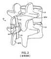
図2に図示されるように、’017出願に記載されているようなインプラント10は、一般的には、一対のコンプライアンス部材16によって接合された上部帯コンポーネント12および下部帯コンポーネント14を備える。上部帯12はL4の棘突起SP4の上に配置されて示され、その一方で、下部帯14はL5の棘突起SP5の底部に延在して示される。コンプライアンス部材16は、一般的には、ゴムブロックのバネ等の内部要素を含み、これは、帯12および14に取り付けられ、棘突起SP4およびSP5が屈曲の際に離れると、帯が「弾性的に」または「従順に」引き離され得る。このようにして、インプラントは、脊椎突起に弾性張力を提供し、これは、屈曲に抵抗する力を提供する。この力は、突起がさらに離れると、一般的に非可変のバネ定数で直線的に増加する。通常は、帯自体には本質的にコンプライアンスがなく、弾性またはコンプライアンスの程度は、コンプライアンス部材16によってのみ制御および提供され得る。 As illustrated in FIG. 2, an
図2に図示されるシステムは、大きな利益を提供するが、棘突起が比較的小さいか、またはある種の形状を有する、ある特定の患者の解剖学的構造に移植する場合には、困難を生じ得る。さらに、仙骨の棘突起が本システムの取り付けに対して必ずしも十分ではないので、本システムは、L5−S1接合部での装着を意図していない。 The system illustrated in FIG. 2 provides significant benefits, but can be difficult when implanted into certain patient anatomy where the spinous processes are relatively small or have some shape. Can occur. Furthermore, the system is not intended for attachment at the L5-S1 junction, as the spinous process of the sacrum is not necessarily sufficient for attachment of the system.
これらの理由により、椎間板性疼痛に罹患する患者における屈曲を抑制するための、改良された脊椎インプラント、およびそれらの使用方法を提供することが望ましい。改良されたインプラントおよび方法が、L5−S1接合部における装着に対して、および’017出願に記載されるような従来システムの装着に関する他の困難を妨げる解剖学的構造を有する患者における装着に対して適する場合には、これは特に望ましい。これらの目的のうちの少なくとも一部は、以下に記載される本発明によって満たされる。 For these reasons, it is desirable to provide improved spinal implants and methods for their use to inhibit flexion in patients suffering from intervertebral disc pain. Improved implants and methods are for mounting at L5-S1 junctions and for mounting in patients with anatomical structures that obstruct other difficulties associated with mounting conventional systems as described in the '017 application. This is particularly desirable where appropriate. At least some of these objectives will be met by the invention described below.
(背景技術の記載)
特許文献1は上に記載された。対象となる他の特許および公開された出願は、特許文献2、特許文献3、特許文献4、特許文献5、特許文献6、特許文献7、特許文献8、特許文献9、特許文献10、特許文献11、特許文献12、特許文献13、特許文献14、特許文献15、特許文献16、特許文献17、特許文献18、特許文献19、特許文献20、特許文献21、特許文献22、特許文献23、特許文献24、特許文献25、特許文献26、特許文献27、特許文献28、特許文献29、特許文献30、特許文献31、特許文献32、特許文献33、特許文献34、特許文献35、特許文献36、特許文献37、特許文献38、特許文献39、特許文献40、特許文献41、特許文献42、特許文献43、特許文献44、特許文献45、特許文献46、および特許文献47、ならびに、公開された特許文献48、特許文献49、特許文献50、特許文献51、特許文献52、特許文献53、特許文献54、特許文献55、特許文献56、および特許文献57、ならびに、公開された特許文献58、特許文献59、特許文献60、特許文献61、特許文献62、特許文献63、および特許文献64、ならびに、公開された外国出願の特許文献65および特許文献66を含む。(Description of background technology)
Patent document 1 was described above. Other patents and published applications covered are Patent Literature 2, Patent Literature 3, Patent Literature 4,
本発明は、医師がセグメントの屈曲を制御することを望む、椎間板性疼痛、および、脊椎すべり症等の他の脊椎の状態の治療のために、脊椎の屈曲を制限するための脊椎インプラントおよび方法を提供する。当該方法は、取り付け具を用いずに、テザー構造の第1のセグメントを、椎骨の棘突起上に配設するステップを含む。テザー構造の少なくとも1つの他のセグメントは、隣接する椎骨または仙骨に取り付けられ、脊椎が屈曲する際に、例えば、患者が前方に傾き、隣接する椎骨または仙骨から棘突起が離れる際に、テザー構造の少なくとも一部が弾性的に伸張して、棘突起と隣接する椎骨または仙骨との間に張力を加えるように構成される。本発明の方法およびインプラントは、脊椎のL4−L5およびL5−S1接合部(図1)を治療するために特に有用である。テザー構造の第1のセグメントは、概ね、図1の帯12に類似のまたは同一のループであり、これは、棘突起に非固定的に取り付けられ、一般的には、上棘突起上に配置されるが、別様に棘突起に取り付けられない。したがって、テザーの第1のセグメントは、脊椎が屈曲および伸展する際に、棘突起に対して、横方向および/または前後方向に移動またはシフトすることができる。 The present invention relates to spinal implants and methods for limiting spinal flexion for the treatment of intervertebral pain and other spinal conditions such as spondylolisthesis that the physician desires to control segment flexion. I will provide a. The method includes disposing a first segment of a tether structure on a spinal process of a vertebra without using an attachment. At least one other segment of the tether structure is attached to the adjacent vertebra or sacrum, and when the spine flexes, for example, when the patient tilts forward and the spinous process leaves the adjacent vertebra or sacrum. At least a portion thereof is configured to elastically stretch to apply tension between the spinous process and the adjacent vertebra or sacrum. The methods and implants of the present invention are particularly useful for treating the spinal L4-L5 and L5-S1 junctions (FIG. 1). The first segment of the tether structure is generally a loop similar or identical to the
テザーの少なくとも1つの他のセグメントは、種々の方法で隣接する椎骨または仙骨に取り付けられ得る。第1の群の実施形態において、テザー構造の少なくとも1つの他のセグメントは、セグメントが取り付け点に対して移動しないように、隣接する椎骨または仙骨に固定的に取り付けられる。例えば、テザー構造の他のセグメントは、例えば、ネジ、ダボ、ステープル、ピン、縫合、などで、椎骨または仙骨に固定的に取り付けられる2つの個別の端セグメントを備え得る。椎骨に取り付けられるときには、2つの個別の端セグメントは、下椎骨の棘突起の反対側に取り付けられ得る。仙骨に取り付けられときには、2つの個別の端セグメントは、一般的には翼状ネジで、仙骨の翼状表面に取り付けられ得る。 At least one other segment of the tether can be attached to the adjacent vertebra or sacrum in a variety of ways. In a first group of embodiments, at least one other segment of the tether structure is fixedly attached to an adjacent vertebra or sacrum so that the segment does not move relative to the attachment point. For example, other segments of the tether structure may comprise two separate end segments that are fixedly attached to the vertebra or sacrum, eg, with screws, dowels, staples, pins, sutures, and the like. When attached to the vertebra, the two separate end segments can be attached to the opposite side of the spinous process of the lower vertebra. When attached to the sacrum, the two separate end segments can be attached to the sacral winged surface, typically with winged screws.
第2の組の実施形態において、テザー構造の少なくとも1つの他のセグメントは、セグメントが取り付け点に対して移動またはシフトし得るように、隣接する椎骨または仙骨に非固定的に取り付けられ得る。例えば、少なくとも1つの他のセグメントは、図2の下部帯14に類似のループを備え得る。穴が隣接する椎骨の棘突起に形成され得、ループが、穴を通って非固定的な取り付けを提供し得る。同様に、テザー構造の下部ループセグメントを受容するために、穴が仙骨の突出する表面構造に形成され得る。代替案として、このようなループセグメントは、下部椎骨または仙骨に植え込まれる1つ以上のアイレットネジの丸環(単数または複数)に通され得る。 In a second set of embodiments, at least one other segment of the tether structure can be non-fixedly attached to an adjacent vertebra or sacrum so that the segment can move or shift relative to the attachment point. For example, the at least one other segment may comprise a loop similar to the
テザー構造は、一般的には、少なくとも1つのコンプライアンス部材を備え、より一般的には、図2の実施形態に関連して概略的に記載されるように、2つのコンプライアンス部材を備える。テザー構造が、少なくとも2つのコンプライアンス部材を備えるときには、コンプライアンス部材の上端の間に延在する少なくとも1つのループセグメントまたは帯が存在する。帯は、通常はコンプライアンスを有しないが、他の実施形態においては、限られたコンプライアンスまたは柔軟性を有し得る。テザー構造が、下部椎骨または仙骨のアイレットまたは穴を通過することを意図されるときには、テザー構造は、図2に概略的に示されるように、さらなる下部ループセグメントまたは帯を備え得る。代替案として、テザー構造は、2つのコンプライアンス部材のそれぞれから延在する個別の端を有する、少なくとも2つの付加的なセグメントを備え得る。個別の端は、ネジ、ダボ、ステープル、または上に記載された任意の技術を使用して、隣接する椎骨または仙骨に固着するように適合される。 The tether structure generally comprises at least one compliance member, and more generally comprises two compliance members, as generally described in connection with the embodiment of FIG. When the tether structure comprises at least two compliance members, there is at least one loop segment or band extending between the upper ends of the compliance members. The band is usually not compliant, but in other embodiments it may have limited compliance or flexibility. When the tether structure is intended to pass through an eyelet or hole in the lower vertebra or sacrum, the tether structure may comprise an additional lower loop segment or band, as shown schematically in FIG. As an alternative, the tether structure may comprise at least two additional segments with separate ends extending from each of the two compliance members. The individual ends are adapted to affix to the adjacent vertebra or sacrum using screws, dowels, staples, or any of the techniques described above.
すべての例において、テザー構造は、一般的には、脊椎の伸展に対する制限または抵抗をほとんど提供しないか、またはまったく提供しない。ほとんどの場合、テザー構造は、隣接する棘突起の間、または棘突起と隣接する仙骨との間に位置する、コンポーネントまたは他の構造から自由である。しかしながら、他の例では、本出願と同一日に出願された、同時係属中の出願第11/777,366号に概略的に記載されているように、クロス部材または他の扁平構造が、2つのコンプライアンス部材の間に配置され、コンプライアンス部材の協調を維持し得る。コンプライアンス部材を安定化するためのクロス部材の使用は、テザー構造の下部が、下部椎骨または仙骨に非固定的に取り付けられているときには、有益であり得る。
本発明のさらなる局面において、脊椎インプラントは、少なくとも2つのコンプライアンス部材を備え、それぞれのコンプライアンス部材は、上端および下端を有する。上部テザー構造は、2つのコンプライアンス部材の上端の間に延在し、第1の椎骨の棘突起上への配置に適合される。一般的には、上部テザー構造は、コンプライアンスを有しない帯である。脊椎インプラントは、上端でコンプライアンス部材の下端に取り付けられ、第1の椎骨に隣接する椎骨または仙骨に固定的に取り付けられるように適合された下端を有する、第1の下部テザー構造をさらに備える。第2の下部テザーセグメントは、その上端で第2のコンプライアンス部材の下端に取り付けられ、第1の椎骨に隣接する椎骨または仙骨に固定的に取り付けられるように適合された下端を有する。第1および第2の下部テザーセグメントの下端は、一般的には、コンプライアンスを有しない帯であり、隣接する椎骨または仙骨にネジ止めされるように適合され得る。代替案として、第1および第2の下部テザーセグメントの下端は、隣接する椎骨または仙骨に植え込まれたダボに取り付けられるように適合され得る。脊椎インプラントは、任意で、テザーセグメントの下端を椎骨または仙骨に固定的に取り付けるための、ネジ、固着具、または他の取り付け部材に適応し得る。In all instances, the tether structure generally provides little or no restriction or resistance to spinal extension. In most cases, the tether structure is free from components or other structures located between adjacent spinous processes or between the spinous processes and the adjacent sacrum. However, in other examples, a cross member or other flat structure may be 2 or 2 as schematically described in co-pending application 11 / 777,366, filed on the same day as this application. It can be placed between two compliance members to maintain coordination of the compliance members. The use of a cross member to stabilize the compliance member can be beneficial when the lower portion of the tether structure is non-fixedly attached to the lower vertebra or sacrum.
In a further aspect of the invention, the spinal implant comprises at least two compliance members, each compliance member having an upper end and a lower end. The upper tether structure extends between the upper ends of the two compliance members and is adapted for placement on the spinous processes of the first vertebra. Generally, the upper tether structure is a non-compliant band. The spinal implant further includes a first lower tether structure attached at the upper end to the lower end of the compliance member and having a lower end adapted to be fixedly attached to a vertebra or sacrum adjacent to the first vertebra. The second lower tether segment is attached at its upper end to the lower end of the second compliance member and has a lower end adapted to be fixedly attached to a vertebra or sacrum adjacent to the first vertebra. The lower ends of the first and second lower tether segments are generally non-compliant bands and can be adapted to be screwed to adjacent vertebrae or sacrum. As an alternative, the lower ends of the first and second lower tether segments can be adapted to be attached to dowels implanted in adjacent vertebrae or sacrum. The spinal implant can optionally accommodate screws, fasteners, or other attachment members for fixedly attaching the lower end of the tether segment to the vertebra or sacrum.
ここで図3を参照すると、本発明の方法に従った使用に適切な脊椎インプラント20は、上部帯22、下部帯24、ならびに上部帯および下部帯を接合する一対のコンプライアンス部材26を備える。一般的には、上部帯および下部帯22および24は、非膨張性であるが、コンプライアンス部材26に接合され、その結果として、患者の脊椎が、屈曲と伸展との間の中立位置にあるときの破線で示される収縮構成から、患者の脊椎が屈曲するときの拡張構成(実線で示される)へと伸張し得る。コンプライアンス部材26は、先の米国特許出願第2005/0216017号(本明細書において参考としてすでに援用されている)に概略的に記載されているように、棘突起SP4およびSP5の伸展に対抗して作用する力を提供する。しかしながら、’017出願の教示とは対照的に、下部帯24はL5の棘突起SP5に非固定的に取り付けられる。下部帯24は、棘突起SP5に形成された穴Hを通ることによって安定的に維持され、外れることはない。 Referring now to FIG. 3, a
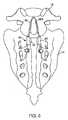
ここで図4を参照すると、脊椎インプラント30は、上部帯32、一対のコンプライアンス部材34、ならびに、第1および第2の下部帯36および38を含むテザー構造を備え得、コンプライアンス部材34のそれぞれから1つの帯が延在する。コンプライアンスおよび弾力性はコンプライアンス部材34によって提供され、下部帯36は、一般的に、上部帯32と同様に、コンプライアンスを有しない。下部帯36および38の下端は、ネジ40または任意の他の適切な固着具を使用して、棘突起SP5に固定的に取り付けられ得る。ネジまたは他の固着具を使用することによって、下部帯36および38は棘突起SP5に固定的に取り付けられ、帯36および38と、棘突起SP5およびL5との間の相対運動を許容しない。(帯が通る)L4とL5との間に伸張する棘間靱帯が、前後方向の運動に抵抗するものの、上部帯32は、対照的に、L4上の上部棘突起SP4に対してわずかに移動またはシフトすることができる。 Referring now to FIG. 4, the
ここで図5を参照すると、図3に概略的に記載された脊椎インプラント20がまた、L5の棘突起SP5と、仙骨Sとの間に装着され得る。上部帯22は、棘突起SP5上に配置され、その一方で、下部帯24は、仙骨の背部表面上の表面の隆起に配置された穴Hを通して配置される。 Referring now to FIG. 5, the
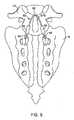
ここで図6を参照すると、上部帯42、一対のコンプライアンス部材44、ならびに下部帯セグメント46および48を備える脊椎インプラント40が、L5の棘突起SP5、および仙骨S上に装着され得る。特に、ダボまたは他の固着具要素が、仙骨のS1棘突起(一般的には、L5棘突起と比較して小さく、帯を輪にすることができる固着部を提供する能力で劣る)に植え込まれ得、下部帯セグメント46および48の下端のリング50および52が、ダボまたは他の固着具上に配置され得る。 Referring now to FIG. 6, a
図7に図示されるように、インプラント60を装着するためのさらなる代替法が図示される。インプラント60は、上部帯62、一対のコンプライアンス部材64、ならびに下部帯セグメント66および68を備える。上部帯セグメントはL5の棘突起SP5上に配置され、その一方で、下部帯セグメント66および68は、翼状ネジ70によって仙骨の翼状領域に固着される。 As illustrated in FIG. 7, a further alternative method for mounting the
図8に図示されるように、インプラント60を装着するためのさらなる代替法が図示される。インプラント60は、上部帯62、一対のコンプライアンス部材64、ならびに下部帯セグメント66および68を備える。上部帯セグメントは、L5の棘突起SP5上に配置され、その一方で、下部帯セグメント66および68は、上関節面ネジ72によって、仙骨の上関節面に固着される。 As illustrated in FIG. 8, a further alternative method for mounting the
図9に図示されるように、インプラント80を装着するためのさらなる代替法が図示される。インプラント80は、上部帯82、一対のコンプライアンス部材84、ならびに下部帯セグメント86および88を備える。上部帯セグメントはL5の棘突起SP5上に配置され、その一方で、下部帯セグメント86および88は、S1の上関節面に作られ穴90を通って、背内側から近位外側へと通され、トグル固着具(T字型固着具)92を介して関節面の近位外側に非固定的に取り付けられる。 As illustrated in FIG. 9, a further alternative method for mounting the implant 80 is illustrated. The implant 80 includes an
図10に図示されるように、インプラント100を装着するためのさらなる代替法が図示される。インプラント100は、上部帯102、一対のコンプライアンス部材104、ならびに下部帯セグメント106および108を備える。上部帯セグメントは、L5の棘突起SP5上に配置され、その一方で、下部帯セグメント106および108は、背部S1の穴Fに取り付けられたフック110に接続される。
本発明は、例えば、以下を提供する:
(項目1)
少なくとも2つのコンプライアンス部材であって、各コンプライアンス部材は上端および下端を有する、コンプライアンス部材と、
該2つのコンプライアンス部材の該上端の間に延在する上部テザー構造であって、該上部テザーセグメントは、棘突起または第1の椎骨上への配置に適合される、上部テザー構造と、
上端で第1の該コンプライアンス部材に取り付けられ、該第1の椎骨に隣接する椎骨または仙骨に固定して取り付けられるように構成される下端を有する、第1の下部テザーセグメントと、
上端で第2の該コンプライアンス部材に取り付けられ、該第1の椎骨に隣接する該椎骨または仙骨に固定して取り付けられるように構成される下端を有する、第2の下部テザーセグメントと、
を備える、脊椎インプラント。
(項目2)
前記第1および第2の下部テザーセグメントの前記下端は、前記隣接する椎骨または仙骨にネジ止めされるように構成される、項目1に記載の脊椎インプラント。
(項目3)
前記第1および第2の下部テザーセグメントの前記下端は、前記隣接する椎骨または仙骨に植え込まれたダボに取り付けられるように構成される、項目1に記載の脊椎インプラント。
(項目4)
前記下端を仙骨に取り付けるための翼状ネジをさらに備える、項目1に記載の脊椎インプラント。
(項目5)
前記下端を仙骨に取り付けるための上関節面ネジをさらに備える、項目1に記載の脊椎インプラント。
(項目6)
前記第1および第2の下部テザーセグメントの前記下端は、上関節面に作られた穴を通って、背内側から近位外側へと通され、かつ該面の該近位外側の固着具によって、該穴の中に固定されるように構成される、項目1に記載の脊椎インプラント。
(項目7)
前記下端を仙骨に取り付けるための翼状ネジをさらに備える、項目1に記載の脊椎インプラント。As illustrated in FIG. 10, a further alternative method for mounting the
The present invention provides, for example:
(Item 1)
At least two compliance members, each compliance member having an upper end and a lower end;
An upper tether structure extending between the upper ends of the two compliance members, wherein the upper tether segment is adapted for placement on a spinous process or first vertebra;
A first lower tether segment having a lower end attached to the first compliance member at an upper end and configured to be fixedly attached to a vertebra or sacrum adjacent to the first vertebra;
A second lower tether segment having a lower end attached to the second compliance member at the upper end and configured to be fixedly attached to the vertebra or sacrum adjacent to the first vertebra;
A spinal implant comprising:
(Item 2)
The spinal implant according to item 1, wherein the lower ends of the first and second lower tether segments are configured to be screwed to the adjacent vertebrae or sacrum.
(Item 3)
The spinal implant of claim 1, wherein the lower ends of the first and second lower tether segments are configured to be attached to dowels implanted in the adjacent vertebrae or sacrum.
(Item 4)
Item 2. The spinal implant of item 1, further comprising a winged screw for attaching the lower end to the sacrum.
(Item 5)
The spinal implant according to item 1, further comprising an upper joint surface screw for attaching the lower end to the sacrum.
(Item 6)
The lower ends of the first and second lower tether segments are passed from a dorsal medial side to a proximal outer side through holes made in the upper articular surface, and by the proximal outer anchors of the surface The spinal implant of claim 1, wherein the spinal implant is configured to be secured within the hole.
(Item 7)
Item 2. The spinal implant of item 1, further comprising a winged screw for attaching the lower end to the sacrum.
上記は、本発明の好適な実施形態の完全な説明であるが、種々の代替法、修正、および均等物が使用され得る。したがって、上記の説明は、添付の請求項によって定義される本発明の範囲を制限するものとして解釈されるべきではない。 While the above is a complete description of the preferred embodiments of the invention, various alternatives, modifications, and equivalents may be used. Therefore, the above description should not be taken as limiting the scope of the invention which is defined by the appended claims.
Claims (7)
Translated fromJapanese該2つのコンプライアンス部材の該上端の間に延在する上部テザーセグメントであって、該上部テザーセグメントは、第1の椎骨の棘突起上への配置に適合される、上部テザーセグメントと、
第1の下部テザーセグメントであって、該第1の下部テザーセグメントが、上端で第1の該コンプライアンス部材に取り付けられ、そして第2の該コンプライアンス部材ではなく、該第1の椎骨より下の第2の椎骨または仙骨の表面に固定して取り付けられるように構成される下端を有する、第1の下部テザーセグメントと、
第2の下部テザーセグメントであって、該第2の下部テザーセグメントが、上端で該第2の該コンプライアンス部材に取り付けられ、そして該第1の該コンプライアンス部材でもなく、該第1の下部テザーセグメントでもなく、該第1の椎骨より下の該椎骨または仙骨の表面に固定して取り付けられるように構成される下端を有する、第2の下部テザーセグメントと、
を備える、脊椎インプラント。At least two compliance members, each compliance member having an upper end and a lower end;
A top tethersegment extending between the upper ends of the two compliance members, said upper tether segment is adapted to the arrangement of thefirst vertebra of Toge突raising, and the upper tethersegment,
A first lower tether segment, wherein the first lower tether segment is attached to the first compliance member atan upper end,and is not a second compliance member, but a secondlower tether segmentbelow the first vertebra. A first lower tether segment having a lower end configured to be fixedly attached tothe surface oftwo vertebrae or sacrum;
A second lower tether segment, the lower tether segment of said second, attached tothe second of said compliance member at the upper end,and neither the compliance member of the first, lower tether segment of said first Rather, a second lower tether segment having a lower end configured to be fixedly attached toa surface of the vertebra or sacrumbelow the first vertebra;
A spinal implant comprising:
Applications Claiming Priority (5)
| Application Number | Priority Date | Filing Date | Title |
|---|---|---|---|
| US86208506P | 2006-10-19 | 2006-10-19 | |
| US60/862,085 | 2006-10-19 | ||
| US11/827,980 | 2007-07-13 | ||
| US11/827,980US8523904B2 (en) | 2004-03-09 | 2007-07-13 | Methods and systems for constraint of spinous processes with attachment |
| PCT/US2007/022191WO2008051423A1 (en) | 2006-10-19 | 2007-10-18 | Methods and systems for constraint of spinous processes with attachment |
Related Child Applications (1)
| Application Number | Title | Priority Date | Filing Date |
|---|---|---|---|
| JP2013043912ADivisionJP5735026B2 (en) | 2006-10-19 | 2013-03-06 | Method and system for constraining spinous processes with a fixture |
Publications (2)
| Publication Number | Publication Date |
|---|---|
| JP2010506661A JP2010506661A (en) | 2010-03-04 |
| JP5220754B2true JP5220754B2 (en) | 2013-06-26 |
Family
ID=39092887
Family Applications (2)
| Application Number | Title | Priority Date | Filing Date |
|---|---|---|---|
| JP2009533363AActiveJP5220754B2 (en) | 2006-10-19 | 2007-10-18 | Method and system for constraining spinous processes with a fixture |
| JP2013043912AActiveJP5735026B2 (en) | 2006-10-19 | 2013-03-06 | Method and system for constraining spinous processes with a fixture |
Family Applications After (1)
| Application Number | Title | Priority Date | Filing Date |
|---|---|---|---|
| JP2013043912AActiveJP5735026B2 (en) | 2006-10-19 | 2013-03-06 | Method and system for constraining spinous processes with a fixture |
Country Status (6)
| Country | Link |
|---|---|
| US (5) | US8523904B2 (en) |
| EP (1) | EP2081508B1 (en) |
| JP (2) | JP5220754B2 (en) |
| AT (1) | ATE507784T1 (en) |
| DE (1) | DE602007014396D1 (en) |
| WO (1) | WO2008051423A1 (en) |
Families Citing this family (71)
| Publication number | Priority date | Publication date | Assignee | Title |
|---|---|---|---|---|
| US6068630A (en)* | 1997-01-02 | 2000-05-30 | St. Francis Medical Technologies, Inc. | Spine distraction implant |
| FR2844179B1 (en)* | 2002-09-10 | 2004-12-03 | Jean Taylor | POSTERIOR VERTEBRAL SUPPORT KIT |
| US8048117B2 (en) | 2003-05-22 | 2011-11-01 | Kyphon Sarl | Interspinous process implant and method of implantation |
| US7909853B2 (en)* | 2004-09-23 | 2011-03-22 | Kyphon Sarl | Interspinous process implant including a binder and method of implantation |
| US7846183B2 (en) | 2004-02-06 | 2010-12-07 | Spinal Elements, Inc. | Vertebral facet joint prosthesis and method of fixation |
| US20220338905A1 (en)* | 2004-03-09 | 2022-10-27 | The Board Of Trustees Of The Leland Stanford Junior University | Methods and systems for constraint of spinous processes with attachment |
| US8523904B2 (en) | 2004-03-09 | 2013-09-03 | The Board Of Trustees Of The Leland Stanford Junior University | Methods and systems for constraint of spinous processes with attachment |
| US7458981B2 (en)* | 2004-03-09 | 2008-12-02 | The Board Of Trustees Of The Leland Stanford Junior University | Spinal implant and method for restricting spinal flexion |
| US9504583B2 (en) | 2004-06-10 | 2016-11-29 | Spinal Elements, Inc. | Implant and method for facet immobilization |
| US7935136B2 (en)* | 2004-06-17 | 2011-05-03 | Alamin Todd F | Facet joint fusion devices and methods |
| US8012209B2 (en)* | 2004-09-23 | 2011-09-06 | Kyphon Sarl | Interspinous process implant including a binder, binder aligner and method of implantation |
| US7901437B2 (en) | 2007-01-26 | 2011-03-08 | Jackson Roger P | Dynamic stabilization member with molded connection |
| US8034079B2 (en) | 2005-04-12 | 2011-10-11 | Warsaw Orthopedic, Inc. | Implants and methods for posterior dynamic stabilization of a spinal motion segment |
| US8105357B2 (en)* | 2006-04-28 | 2012-01-31 | Warsaw Orthopedic, Inc. | Interspinous process brace |
| EP2015681B1 (en) | 2006-05-03 | 2018-03-28 | Datascope Corp. | Tissue closure device |
| FR2907329B1 (en)* | 2006-10-20 | 2009-02-27 | Jean Taylor | INTEREPINEAL VERTEBRAL PROSTHESIS |
| US8162982B2 (en)* | 2006-10-19 | 2012-04-24 | Simpirica Spine, Inc. | Methods and systems for constraint of multiple spine segments |
| US8029541B2 (en)* | 2006-10-19 | 2011-10-04 | Simpirica Spine, Inc. | Methods and systems for laterally stabilized constraint of spinous processes |
| ES2364417T3 (en) | 2006-10-19 | 2011-09-01 | The Board Of Trustees Of The Leland Stanford Junior University | SYSTEMS FOR THE LIMITATION OF SPINE APOPHYSIS WITH CLAMPS. |
| US8187307B2 (en)* | 2006-10-19 | 2012-05-29 | Simpirica Spine, Inc. | Structures and methods for constraining spinal processes with single connector |
| US20080262549A1 (en)* | 2006-10-19 | 2008-10-23 | Simpirica Spine, Inc. | Methods and systems for deploying spinous process constraints |
| US20080114357A1 (en)* | 2006-11-15 | 2008-05-15 | Warsaw Orthopedic, Inc. | Inter-transverse process spacer device and method for use in correcting a spinal deformity |
| US8992533B2 (en) | 2007-02-22 | 2015-03-31 | Spinal Elements, Inc. | Vertebral facet joint drill and method of use |
| EP2813190B1 (en) | 2007-02-22 | 2017-04-26 | Spinal Elements, Inc. | Vertebral facet joint drill |
| US20110172708A1 (en)* | 2007-06-22 | 2011-07-14 | Simpirica Spine, Inc. | Methods and systems for increasing the bending stiffness of a spinal segment with elongation limit |
| US20100036424A1 (en) | 2007-06-22 | 2010-02-11 | Simpirica Spine, Inc. | Methods and systems for increasing the bending stiffness and constraining the spreading of a spinal segment |
| EP2182864B1 (en) | 2007-06-22 | 2016-06-08 | Empirical Spine, Inc. | Devices for controlled flexion restriction of spinal segments |
| WO2009149399A1 (en) | 2008-06-06 | 2009-12-10 | Simpirica Spine, Inc. | Methods and apparatus for deploying spinous process constraints |
| WO2009149414A1 (en) | 2008-06-06 | 2009-12-10 | Simpirica Spine, Inc. | Methods and apparatus for locking a band |
| EP2296567B1 (en) | 2008-06-06 | 2014-03-12 | Simpirica Spine, Inc. | Apparatus for locking a band |
| JP5687197B2 (en) | 2008-09-03 | 2015-03-18 | シンピライカ スパイン, インコーポレイテッド | Method and apparatus for coupling a prosthesis to a spinal segment |
| EP2355727A4 (en)* | 2008-11-24 | 2013-01-09 | Simpirica Spine Inc | Methods and devices for restricting flexion and extension of a spinal segment |
| US8114135B2 (en)* | 2009-01-16 | 2012-02-14 | Kyphon Sarl | Adjustable surgical cables and methods for treating spinal stenosis |
| WO2010088621A1 (en) | 2009-02-02 | 2010-08-05 | Simpirica Spine, Inc. | Sacral tether anchor and methods of use |
| WO2010104975A1 (en) | 2009-03-10 | 2010-09-16 | Simpirica Spine, Inc. | Surgical tether apparatus and methods of use |
| WO2010104935A1 (en) | 2009-03-10 | 2010-09-16 | Simpirica Spine, Inc. | Surgical tether apparatus and methods of use |
| EP2405840B1 (en) | 2009-03-10 | 2024-02-21 | Empirical Spine, Inc. | Surgical tether apparatus |
| US8668719B2 (en) | 2009-03-30 | 2014-03-11 | Simpirica Spine, Inc. | Methods and apparatus for improving shear loading capacity of a spinal segment |
| US20100312343A1 (en)* | 2009-06-04 | 2010-12-09 | Linares Medical Devices, Llc | Tip support insert for application to left/right articular processes to minimize abrasion between vertebrae and to maintain proper angle/lift for reducing nerve compression |
| US9668771B2 (en) | 2009-06-15 | 2017-06-06 | Roger P Jackson | Soft stabilization assemblies with off-set connector |
| EP3017793A3 (en) | 2010-07-15 | 2016-08-17 | Spine Wave, Inc. | A plastically deformable inter-osseous device |
| WO2012048131A2 (en) | 2010-10-06 | 2012-04-12 | Simpirica Spine, Inc. | Device and accessories for limiting flexion |
| US8496689B2 (en) | 2011-02-23 | 2013-07-30 | Farzad Massoudi | Spinal implant device with fusion cage and fixation plates and method of implanting |
| USD724733S1 (en) | 2011-02-24 | 2015-03-17 | Spinal Elements, Inc. | Interbody bone implant |
| US9271765B2 (en) | 2011-02-24 | 2016-03-01 | Spinal Elements, Inc. | Vertebral facet joint fusion implant and method for fusion |
| US8740949B2 (en) | 2011-02-24 | 2014-06-03 | Spinal Elements, Inc. | Methods and apparatus for stabilizing bone |
| US8425560B2 (en) | 2011-03-09 | 2013-04-23 | Farzad Massoudi | Spinal implant device with fixation plates and lag screws and method of implanting |
| USD739935S1 (en) | 2011-10-26 | 2015-09-29 | Spinal Elements, Inc. | Interbody bone implant |
| US8961570B2 (en) | 2012-01-24 | 2015-02-24 | Warsaw Othopedic, Inc. | Spinal correction system and method |
| US9820784B2 (en)* | 2013-03-14 | 2017-11-21 | Spinal Elements, Inc. | Apparatus for spinal fixation and methods of use |
| USD765853S1 (en) | 2013-03-14 | 2016-09-06 | Spinal Elements, Inc. | Flexible elongate member with a portion configured to receive a bone anchor |
| US9421044B2 (en) | 2013-03-14 | 2016-08-23 | Spinal Elements, Inc. | Apparatus for bone stabilization and distraction and methods of use |
| FR3010628B1 (en) | 2013-09-18 | 2015-10-16 | Medicrea International | METHOD FOR REALIZING THE IDEAL CURVATURE OF A ROD OF A VERTEBRAL OSTEOSYNTHESIS EQUIPMENT FOR STRENGTHENING THE VERTEBRAL COLUMN OF A PATIENT |
| US9456855B2 (en) | 2013-09-27 | 2016-10-04 | Spinal Elements, Inc. | Method of placing an implant between bone portions |
| US9839450B2 (en) | 2013-09-27 | 2017-12-12 | Spinal Elements, Inc. | Device and method for reinforcement of a facet |
| FR3012030B1 (en) | 2013-10-18 | 2015-12-25 | Medicrea International | METHOD FOR REALIZING THE IDEAL CURVATURE OF A ROD OF A VERTEBRAL OSTEOSYNTHESIS EQUIPMENT FOR STRENGTHENING THE VERTEBRAL COLUMN OF A PATIENT |
| WO2015077356A1 (en) | 2013-11-19 | 2015-05-28 | Wheeler William K | Fastener applicator with interlock |
| US11478275B2 (en) | 2014-09-17 | 2022-10-25 | Spinal Elements, Inc. | Flexible fastening band connector |
| AU2016212009C1 (en) | 2015-01-27 | 2021-02-25 | Spinal Elements, Inc. | Facet joint implant |
| WO2018009671A1 (en) | 2016-07-07 | 2018-01-11 | Stern Mark S | Spinous laminar clamp assembly |
| US10456174B2 (en)* | 2017-07-31 | 2019-10-29 | Medos International Sarl | Connectors for use in systems and methods for reducing the risk of proximal junctional kyphosis |
| US10463403B2 (en) | 2017-07-31 | 2019-11-05 | Medos International Sarl | Systems and methods for reducing the risk of proximal junctional kyphosis using a bone anchor or other attachment point |
| US10918422B2 (en)* | 2017-12-01 | 2021-02-16 | Medicrea International | Method and apparatus for inhibiting proximal junctional failure |
| JP7348199B2 (en) | 2018-03-28 | 2023-09-20 | データスコープ コーポレイション | Device for atrial appendage exclusion |
| CN110110477B (en)* | 2019-05-20 | 2020-04-10 | 哈尔滨理工大学 | Method for establishing auxiliary bow correction torque prediction model for depression |
| US11457959B2 (en) | 2019-05-22 | 2022-10-04 | Spinal Elements, Inc. | Bone tie and bone tie inserter |
| BR112021022695A2 (en) | 2019-05-22 | 2021-12-28 | Spinal Elements Inc | Bone tethering and bone tethering inserter |
| US11406425B2 (en)* | 2019-08-14 | 2022-08-09 | Warsaw Orthopedic, Inc. | Tethers for use with fastener assemblies and method for using tethers with fastener assemblies |
| WO2021163313A1 (en) | 2020-02-14 | 2021-08-19 | Spinal Elements, Inc. | Bone tie methods |
| US12310629B2 (en)* | 2021-02-10 | 2025-05-27 | Alphatec Spine, Inc. | Methods and devices for augmenting the spine |
| US12369952B2 (en) | 2021-12-10 | 2025-07-29 | Spinal Elements, Inc. | Bone tie and portal |
Family Cites Families (209)
| Publication number | Priority date | Publication date | Assignee | Title |
|---|---|---|---|---|
| US3648691A (en)* | 1970-02-24 | 1972-03-14 | Univ Colorado State Res Found | Method of applying vertebral appliance |
| US4246660A (en)* | 1978-12-26 | 1981-01-27 | Queen's University At Kingston | Artificial ligament |
| US4643178A (en)* | 1984-04-23 | 1987-02-17 | Fabco Medical Products, Inc. | Surgical wire and method for the use thereof |
| US4743260A (en)* | 1985-06-10 | 1988-05-10 | Burton Charles V | Method for a flexible stabilization system for a vertebral column |
| US4773402A (en) | 1985-09-13 | 1988-09-27 | Isola Implants, Inc. | Dorsal transacral surgical implant |
| US4708132A (en) | 1986-01-24 | 1987-11-24 | Pfizer-Hospital Products Group, Inc. | Fixation device for a ligament or tendon prosthesis |
| ZA875425B (en) | 1986-07-23 | 1988-04-27 | Gore & Ass | Mechanical ligament |
| US4794916A (en)* | 1986-11-20 | 1989-01-03 | Porterfield James A | Lumbar stabilizer |
| US4772286A (en) | 1987-02-17 | 1988-09-20 | E. Marlowe Goble | Ligament attachment method and apparatus |
| GB8718708D0 (en)* | 1987-08-07 | 1987-09-16 | Mehdian S M H | Apparatus for treatment of spinal disorders |
| FR2623085B1 (en)* | 1987-11-16 | 1992-08-14 | Breard Francis | SURGICAL IMPLANT TO LIMIT THE RELATIVE MOVEMENT OF VERTEBRES |
| FR2625097B1 (en) | 1987-12-23 | 1990-05-18 | Cote Sarl | INTER-SPINOUS PROSTHESIS COMPOSED OF SEMI-ELASTIC MATERIAL COMPRISING A TRANSFILING EYE AT ITS END AND INTER-SPINOUS PADS |
| US5011494A (en)* | 1988-09-16 | 1991-04-30 | Clemson University | Soft tissue implant with micron-scale surface texture to optimize anchorage |
| GB8825909D0 (en)* | 1988-11-04 | 1988-12-07 | Showell A W Sugicraft Ltd | Pedicle engaging means |
| US4870957A (en) | 1988-12-27 | 1989-10-03 | Marlowe Goble E | Ligament anchor system |
| US4966600A (en) | 1989-01-26 | 1990-10-30 | Songer Robert J | Surgical securance method |
| US5116340A (en)* | 1989-01-26 | 1992-05-26 | Songer Robert J | Surgical securance apparatus |
| FR2642645B1 (en)* | 1989-02-03 | 1992-08-14 | Breard Francis | FLEXIBLE INTERVERTEBRAL STABILIZER AND METHOD AND APPARATUS FOR CONTROLLING ITS VOLTAGE BEFORE PLACEMENT ON THE RACHIS |
| USRE36221E (en)* | 1989-02-03 | 1999-06-01 | Breard; Francis Henri | Flexible inter-vertebral stabilizer as well as process and apparatus for determining or verifying its tension before installation on the spinal column |
| US4955910A (en) | 1989-07-17 | 1990-09-11 | Boehringer Mannheim Corporation | Fixation system for an elongated prosthesis |
| US5002574A (en)* | 1989-08-18 | 1991-03-26 | Minnesota Mining And Manufacturing Co. | Tensioning means for prosthetic devices |
| US5108433A (en)* | 1989-08-18 | 1992-04-28 | Minnesota Mining And Manufacturing Company | Tensioning means for prosthetic devices |
| US5030220A (en)* | 1990-03-29 | 1991-07-09 | Advanced Spine Fixation Systems Incorporated | Spine fixation system |
| DE59100448D1 (en) | 1990-04-20 | 1993-11-11 | Sulzer Ag | Implant, in particular intervertebral prosthesis. |
| FR2666981B1 (en)* | 1990-09-21 | 1993-06-25 | Commarmond Jacques | SYNTHETIC LIGAMENT VERTEBRAL. |
| FR2672202B1 (en)* | 1991-02-05 | 1993-07-30 | Safir | BONE SURGICAL IMPLANT, ESPECIALLY FOR INTERVERTEBRAL STABILIZER. |
| FR2681525A1 (en) | 1991-09-19 | 1993-03-26 | Medical Op | Device for flexible or semi-rigid stabilisation of the spine, in particular of the human spine, by a posterior route |
| GB9122753D0 (en)* | 1991-10-26 | 1991-12-11 | Reis Nicolas D | Internal ilio-lumbar fixator |
| FR2693364B1 (en) | 1992-07-07 | 1995-06-30 | Erpios Snc | INTERVERTEBRAL PROSTHESIS FOR STABILIZING ROTATORY AND FLEXIBLE-EXTENSION CONSTRAINTS. |
| GB9217578D0 (en)* | 1992-08-19 | 1992-09-30 | Surgicarft Ltd | Surgical implants,etc |
| US5456722A (en)* | 1993-01-06 | 1995-10-10 | Smith & Nephew Richards Inc. | Load bearing polymeric cable |
| US5540703A (en)* | 1993-01-06 | 1996-07-30 | Smith & Nephew Richards Inc. | Knotted cable attachment apparatus formed of braided polymeric fibers |
| US5496318A (en)* | 1993-01-08 | 1996-03-05 | Advanced Spine Fixation Systems, Inc. | Interspinous segmental spine fixation device |
| US5415661A (en)* | 1993-03-24 | 1995-05-16 | University Of Miami | Implantable spinal assist device |
| FR2703239B1 (en) | 1993-03-30 | 1995-06-02 | Brio Bio Rhone Implant Medical | Clip for interspinous prosthesis. |
| US5540698A (en)* | 1993-04-21 | 1996-07-30 | Amei Technologies Inc. | System and method for securing a medical cable |
| US5449361A (en) | 1993-04-21 | 1995-09-12 | Amei Technologies Inc. | Orthopedic cable tensioner |
| FR2704745B1 (en) | 1993-05-07 | 1995-11-24 | Erpios | Device for connecting the ends of a ligament for osteosynthesis, in particular for vertebral osteosynthesis. |
| FR2709246B1 (en) | 1993-08-27 | 1995-09-29 | Martin Jean Raymond | Dynamic implanted spinal orthosis. |
| US5395374A (en)* | 1993-09-02 | 1995-03-07 | Danek Medical, Inc. | Orthopedic cabling method and apparatus |
| US5354917A (en) | 1993-11-12 | 1994-10-11 | Texaco Chemical Company | Use of supported rhodium catalysts in the preparation of tertiary butyl alcohol from tertiary butyl hydroperoxide |
| FR2712481B1 (en) | 1993-11-18 | 1996-01-12 | Graf Henry | Improvements to flexible inter-vertebral stabilizers. |
| US5415658A (en)* | 1993-12-14 | 1995-05-16 | Pioneer Laboratories, Inc. | Surgical cable loop connector |
| FR2714591B1 (en) | 1994-01-06 | 1996-03-01 | Euros Sa | Prosthetic element for the lumbosacral joint. |
| US5462542A (en) | 1994-01-24 | 1995-10-31 | United States Surgical Corporation | Sternum buckle with serrated strap |
| CA2141911C (en) | 1994-02-24 | 2002-04-23 | Jude S. Sauer | Surgical crimping device and method of use |
| FR2717675B1 (en) | 1994-03-24 | 1996-05-03 | Jean Taylor | Interspinous wedge. |
| US5458601A (en) | 1994-03-28 | 1995-10-17 | Medical University Of South Carolina | Adjustable ligament anchor |
| FR2722980B1 (en) | 1994-07-26 | 1996-09-27 | Samani Jacques | INTERTEPINOUS VERTEBRAL IMPLANT |
| US5562653A (en) | 1994-11-16 | 1996-10-08 | Hercules Incorporated | Medical devices composed of low ceiling temperature polymers |
| ATE214897T1 (en)* | 1994-11-16 | 2002-04-15 | Advanced Spine Fixation Syst | GRIP HOOK FOR FIXING THE SPINAL SEGMENTS |
| US5645084A (en)* | 1995-06-07 | 1997-07-08 | Danek Medical, Inc. | Method for spinal fusion without decortication |
| EP0743045A2 (en) | 1995-04-28 | 1996-11-20 | Gazzani, Romolo Igino | Devices for osteosynthesis |
| US5707379A (en)* | 1995-10-20 | 1998-01-13 | Coral Medical | Method and apparatus for intracorporeal suturing |
| DE19627864C2 (en)* | 1996-07-11 | 2003-05-08 | Aesculap Ag & Co Kg | Surgical jig |
| US6835207B2 (en)* | 1996-07-22 | 2004-12-28 | Fred Zacouto | Skeletal implant |
| KR100189371B1 (en) | 1996-08-23 | 1999-06-01 | 전주범 | Interpolator of Digital Demodulator |
| AU4480097A (en) | 1996-09-20 | 1998-04-14 | Medicinelodge, Inc. | Adjustable length strap and footing for ligament mounting and method for its use |
| US5810815A (en)* | 1996-09-20 | 1998-09-22 | Morales; Jose A. | Surgical apparatus for use in the treatment of spinal deformities |
| US6451019B1 (en) | 1998-10-20 | 2002-09-17 | St. Francis Medical Technologies, Inc. | Supplemental spine fixation device and method |
| US6712819B2 (en)* | 1998-10-20 | 2004-03-30 | St. Francis Medical Technologies, Inc. | Mating insertion instruments for spinal implants and methods of use |
| US5860977A (en) | 1997-01-02 | 1999-01-19 | Saint Francis Medical Technologies, Llc | Spine distraction implant and method |
| US6068630A (en) | 1997-01-02 | 2000-05-30 | St. Francis Medical Technologies, Inc. | Spine distraction implant |
| US5836948A (en)* | 1997-01-02 | 1998-11-17 | Saint Francis Medical Technologies, Llc | Spine distraction implant and method |
| US7201751B2 (en)* | 1997-01-02 | 2007-04-10 | St. Francis Medical Technologies, Inc. | Supplemental spine fixation device |
| ES2297092T3 (en)* | 1997-02-11 | 2008-05-01 | Warsaw Orthopedic, Inc. | PREVIOUS CERVICAL PLATE OF UNIQUE BLOCK. |
| US6287308B1 (en) | 1997-07-14 | 2001-09-11 | Sdgi Holdings, Inc. | Methods and apparatus for fusionless treatment of spinal deformities |
| US6828357B1 (en) | 1997-07-31 | 2004-12-07 | Metabolix, Inc. | Polyhydroxyalkanoate compositions having controlled degradation rates |
| US6053921A (en)* | 1997-08-26 | 2000-04-25 | Spinal Concepts, Inc. | Surgical cable system and method |
| US5964769A (en)* | 1997-08-26 | 1999-10-12 | Spinal Concepts, Inc. | Surgical cable system and method |
| US6322279B1 (en) | 1997-11-04 | 2001-11-27 | Sports Carriers, Inc. | Adjustable attachment device |
| US6395018B1 (en)* | 1998-02-09 | 2002-05-28 | Wilfrido R. Castaneda | Endovascular graft and process for bridging a defect in a main vessel near one of more branch vessels |
| FR2775183B1 (en) | 1998-02-20 | 2000-08-04 | Jean Taylor | INTER-SPINOUS PROSTHESIS |
| US6290724B1 (en) | 1998-05-27 | 2001-09-18 | Nuvasive, Inc. | Methods for separating and stabilizing adjacent vertebrae |
| US6224630B1 (en)* | 1998-05-29 | 2001-05-01 | Advanced Bio Surfaces, Inc. | Implantable tissue repair device |
| US6652527B2 (en) | 1998-10-20 | 2003-11-25 | St. Francis Medical Technologies, Inc. | Supplemental spine fixation device and method |
| US5989256A (en) | 1999-01-19 | 1999-11-23 | Spineology, Inc. | Bone fixation cable ferrule |
| WO2000059388A1 (en) | 1999-04-05 | 2000-10-12 | Surgical Dynamics, Inc. | Artificial spinal ligament |
| US6296643B1 (en) | 1999-04-23 | 2001-10-02 | Sdgi Holdings, Inc. | Device for the correction of spinal deformities through vertebral body tethering without fusion |
| US6436099B1 (en) | 1999-04-23 | 2002-08-20 | Sdgi Holdings, Inc. | Adjustable spinal tether |
| US6299613B1 (en) | 1999-04-23 | 2001-10-09 | Sdgi Holdings, Inc. | Method for the correction of spinal deformities through vertebral body tethering without fusion |
| FR2799640B1 (en) | 1999-10-15 | 2002-01-25 | Spine Next Sa | IMPLANT INTERVETEBRAL |
| US6378289B1 (en)* | 1999-11-19 | 2002-04-30 | Pioneer Surgical Technology | Methods and apparatus for clamping surgical wires or cables |
| US6558389B2 (en) | 1999-11-30 | 2003-05-06 | Ron Clark | Endosteal tibial ligament fixation with adjustable tensioning |
| GB9929599D0 (en) | 1999-12-15 | 2000-02-09 | Atlantech Medical Devices Limi | A graft suspension device |
| US6629975B1 (en) | 1999-12-20 | 2003-10-07 | Pioneer Laboratories, Icn. | Multiple lumen crimp |
| US6899716B2 (en)* | 2000-02-16 | 2005-05-31 | Trans1, Inc. | Method and apparatus for spinal augmentation |
| US6248106B1 (en)* | 2000-02-25 | 2001-06-19 | Bret Ferree | Cross-coupled vertebral stabilizers |
| US6402750B1 (en)* | 2000-04-04 | 2002-06-11 | Spinlabs, Llc | Devices and methods for the treatment of spinal disorders |
| US6312431B1 (en) | 2000-04-24 | 2001-11-06 | Wilson T. Asfora | Vertebrae linking system |
| US6427080B1 (en)* | 2000-05-16 | 2002-07-30 | Richard E. Radak | Cervical spine gauge and process |
| US6964667B2 (en)* | 2000-06-23 | 2005-11-15 | Sdgi Holdings, Inc. | Formed in place fixation system with thermal acceleration |
| US6605091B1 (en) | 2000-06-30 | 2003-08-12 | Pioneer Laboratories, Inc. | Surgical cable assembly and method |
| FR2811540B1 (en) | 2000-07-12 | 2003-04-25 | Spine Next Sa | IMPORTING INTERVERTEBRAL IMPLANT |
| FR2811543B1 (en)* | 2000-07-12 | 2003-07-04 | Spine Next Sa | INTERSOMATIC IMPLANT |
| JP2004516044A (en) | 2000-08-08 | 2004-06-03 | エスディージーアイ・ホールディングス・インコーポレーテッド | Method and apparatus for improving stereotactic body transplantation |
| EP1192908A3 (en)* | 2000-10-02 | 2004-05-26 | Howmedica Osteonics Corp. | System and method for spinal reconstruction |
| US6468309B1 (en)* | 2000-10-05 | 2002-10-22 | Cleveland Clinic Foundation | Method and apparatus for stabilizing adjacent bones |
| AU2002239723B2 (en)* | 2000-10-24 | 2004-08-26 | The Spineology Group, Llc | Tension band clip |
| US6488683B2 (en)* | 2000-11-08 | 2002-12-03 | Cleveland Clinic Foundation | Method and apparatus for correcting spinal deformity |
| FR2817461B1 (en)* | 2000-12-01 | 2003-08-15 | Henry Graf | INTERVERTEBRAL STABILIZATION DEVICE |
| US6752831B2 (en) | 2000-12-08 | 2004-06-22 | Osteotech, Inc. | Biocompatible osteogenic band for repair of spinal disorders |
| FR2818530B1 (en) | 2000-12-22 | 2003-10-31 | Spine Next Sa | INTERVERTEBRAL IMPLANT WITH DEFORMABLE SHIM |
| US6364883B1 (en)* | 2001-02-23 | 2002-04-02 | Albert N. Santilli | Spinous process clamp for spinal fusion and method of operation |
| US6652585B2 (en) | 2001-02-28 | 2003-11-25 | Sdgi Holdings, Inc. | Flexible spine stabilization system |
| US7229441B2 (en) | 2001-02-28 | 2007-06-12 | Warsaw Orthopedic, Inc. | Flexible systems for spinal stabilization and fixation |
| FR2822051B1 (en)* | 2001-03-13 | 2004-02-27 | Spine Next Sa | INTERVERTEBRAL IMPLANT WITH SELF-LOCKING ATTACHMENT |
| US6582433B2 (en)* | 2001-04-09 | 2003-06-24 | St. Francis Medical Technologies, Inc. | Spine fixation device and method |
| US6589246B1 (en) | 2001-04-26 | 2003-07-08 | Poly-4 Medical, Inc. | Method of applying an active compressive force continuously across a fracture |
| FI113308B (en) | 2001-06-14 | 2004-03-31 | Abb Oy | Permanent magnet element and electric machine |
| GB0114783D0 (en) | 2001-06-16 | 2001-08-08 | Sengupta Dilip K | A assembly for the stabilisation of vertebral bodies of the spine |
| FR2828398B1 (en) | 2001-08-08 | 2003-09-19 | Jean Taylor | VERTEBRA STABILIZATION ASSEMBLY |
| US6736815B2 (en) | 2001-09-06 | 2004-05-18 | Core Medical, Inc. | Apparatus and methods for treating spinal discs |
| JP4100890B2 (en)* | 2001-09-11 | 2008-06-11 | ペンタックス株式会社 | Lingual spacer |
| US6695852B2 (en)* | 2001-10-31 | 2004-02-24 | Spineology, Inc. | Tension tools for tension band clip |
| US7285121B2 (en)* | 2001-11-05 | 2007-10-23 | Warsaw Orthopedic, Inc. | Devices and methods for the correction and treatment of spinal deformities |
| FR2832917B1 (en) | 2001-11-30 | 2004-09-24 | Spine Next Sa | ELASTICALLY DEFORMABLE INTERVERTEBRAL IMPLANT |
| JP2003232314A (en) | 2002-02-08 | 2003-08-22 | Showa Ika Kohgyo Co Ltd | Rod interval retaining tool |
| US6669729B2 (en) | 2002-03-08 | 2003-12-30 | Kingsley Richard Chin | Apparatus and method for the replacement of posterior vertebral elements |
| US7052497B2 (en)* | 2002-08-14 | 2006-05-30 | Sdgi Holdings, Inc. | Techniques for spinal surgery and attaching constructs to vertebral elements |
| FR2844179B1 (en) | 2002-09-10 | 2004-12-03 | Jean Taylor | POSTERIOR VERTEBRAL SUPPORT KIT |
| US7608094B2 (en)* | 2002-10-10 | 2009-10-27 | U.S. Spinal Technologies, Llc | Percutaneous facet fixation system |
| US20060064165A1 (en) | 2004-09-23 | 2006-03-23 | St. Francis Medical Technologies, Inc. | Interspinous process implant including a binder and method of implantation |
| US7909853B2 (en)* | 2004-09-23 | 2011-03-22 | Kyphon Sarl | Interspinous process implant including a binder and method of implantation |
| US20040210310A1 (en) | 2002-12-10 | 2004-10-21 | Trieu Hai H. | Implant system and method for intervertebral disc augmentation |
| US20050055096A1 (en) | 2002-12-31 | 2005-03-10 | Depuy Spine, Inc. | Functional spinal unit prosthetic |
| US7101398B2 (en)* | 2002-12-31 | 2006-09-05 | Depuy Acromed, Inc. | Prosthetic facet joint ligament |
| FR2850009B1 (en) | 2003-01-20 | 2005-12-23 | Spine Next Sa | TREATMENT ASSEMBLY FOR THE DEGENERATION OF AN INTERVERTEBRAL DISC |
| WO2007035884A2 (en)* | 2005-09-20 | 2007-03-29 | Pioneer Surgical Technology, Inc. | Spinal fixation systems |
| US7335203B2 (en)* | 2003-02-12 | 2008-02-26 | Kyphon Inc. | System and method for immobilizing adjacent spinous processes |
| FR2851154B1 (en) | 2003-02-19 | 2006-07-07 | Sdgi Holding Inc | INTER-SPINOUS DEVICE FOR BRAKING THE MOVEMENTS OF TWO SUCCESSIVE VERTEBRATES, AND METHOD FOR MANUFACTURING THE SAME THEREOF |
| CA2524145A1 (en)* | 2003-05-02 | 2004-11-18 | Yale University | Dynamic spine stabilizer |
| JP5078355B2 (en)* | 2003-05-23 | 2012-11-21 | グローバス メディカル インコーポレイティッド | Spine stabilization system |
| US6986771B2 (en)* | 2003-05-23 | 2006-01-17 | Globus Medical, Inc. | Spine stabilization system |
| FR2858546B1 (en)* | 2003-08-04 | 2006-04-28 | Spine Next Sa | INTERVERTEBRAL DISC PROSTHESIS |
| US7815665B2 (en) | 2003-09-24 | 2010-10-19 | N Spine, Inc. | Adjustable spinal stabilization system |
| WO2005037150A1 (en)* | 2003-10-16 | 2005-04-28 | Osteotech, Inc. | System and method for flexible correction of bony motion segment |
| US7591837B2 (en) | 2003-10-28 | 2009-09-22 | Pyramid Spine, Llc | Facet triangle spinal fixation device and method of use |
| US8632570B2 (en) | 2003-11-07 | 2014-01-21 | Biedermann Technologies Gmbh & Co. Kg | Stabilization device for bones comprising a spring element and manufacturing method for said spring element |
| US8133500B2 (en)* | 2003-12-04 | 2012-03-13 | Kensey Nash Bvf Technology, Llc | Compressed high density fibrous polymers suitable for implant |
| US7553320B2 (en)* | 2003-12-10 | 2009-06-30 | Warsaw Orthopedic, Inc. | Method and apparatus for replacing the function of facet joints |
| US20050192581A1 (en)* | 2004-02-27 | 2005-09-01 | Molz Fred J. | Radiopaque, coaxial orthopedic tether design and method |
| US8636802B2 (en) | 2004-03-06 | 2014-01-28 | DePuy Synthes Products, LLC | Dynamized interspinal implant |
| US8523904B2 (en) | 2004-03-09 | 2013-09-03 | The Board Of Trustees Of The Leland Stanford Junior University | Methods and systems for constraint of spinous processes with attachment |
| US7458981B2 (en) | 2004-03-09 | 2008-12-02 | The Board Of Trustees Of The Leland Stanford Junior University | Spinal implant and method for restricting spinal flexion |
| WO2006071251A2 (en) | 2004-04-07 | 2006-07-06 | Tiax Llc | Tourniquet and method of using same |
| US7452351B2 (en) | 2004-04-16 | 2008-11-18 | Kyphon Sarl | Spinal diagnostic methods and apparatus |
| US7524324B2 (en)* | 2004-04-28 | 2009-04-28 | Kyphon Sarl | System and method for an interspinous process implant as a supplement to a spine stabilization implant |
| US20050267470A1 (en) | 2004-05-13 | 2005-12-01 | Mcbride Duncan Q | Spinal stabilization system to flexibly connect vertebrae |
| US20080033552A1 (en)* | 2004-05-17 | 2008-02-07 | Canon Kasushiki Kaisha | Sensor Device |
| US7658753B2 (en)* | 2004-08-03 | 2010-02-09 | K Spine, Inc. | Device and method for correcting a spinal deformity |
| FR2874167B1 (en) | 2004-08-12 | 2006-11-10 | Philippe Mengus | INTER SPINE DAMPER |
| US7559951B2 (en)* | 2004-09-30 | 2009-07-14 | Depuy Products, Inc. | Adjustable, remote-controllable orthopaedic prosthesis and associated method |
| US20060084976A1 (en)* | 2004-09-30 | 2006-04-20 | Depuy Spine, Inc. | Posterior stabilization systems and methods |
| US7766940B2 (en) | 2004-12-30 | 2010-08-03 | Depuy Spine, Inc. | Posterior stabilization system |
| US7918875B2 (en)* | 2004-10-25 | 2011-04-05 | Lanx, Inc. | Interspinous distraction devices and associated methods of insertion |
| US20060106381A1 (en) | 2004-11-18 | 2006-05-18 | Ferree Bret A | Methods and apparatus for treating spinal stenosis |
| WO2006066053A1 (en)* | 2004-12-15 | 2006-06-22 | Stryker Spine | Spinal rods having segments of different elastic properties and methods of using them |
| US8029549B2 (en) | 2005-02-17 | 2011-10-04 | Kyphon Sarl | Percutaneous spinal implants and methods |
| US20060195102A1 (en) | 2005-02-17 | 2006-08-31 | Malandain Hugues F | Apparatus and method for treatment of spinal conditions |
| US7862590B2 (en) | 2005-04-08 | 2011-01-04 | Warsaw Orthopedic, Inc. | Interspinous process spacer |
| FR2884136B1 (en) | 2005-04-08 | 2008-02-22 | Spinevision Sa | INTERVERTEBRAL SURGICAL IMPLANT FORMING BALL |
| US8034079B2 (en) | 2005-04-12 | 2011-10-11 | Warsaw Orthopedic, Inc. | Implants and methods for posterior dynamic stabilization of a spinal motion segment |
| US7883532B2 (en) | 2005-04-25 | 2011-02-08 | Spineco, Inc. | Vertebral pars interarticularis clamp a new spine fixation device, instrumentation, and methodology |
| US20060271055A1 (en) | 2005-05-12 | 2006-11-30 | Jeffery Thramann | Spinal stabilization |
| AU2006261357A1 (en)* | 2005-06-17 | 2006-12-28 | Zimmer Spine Austin, Inc. | Improved method of treating degenerative spinal disorders |
| US8273088B2 (en)* | 2005-07-08 | 2012-09-25 | Depuy Spine, Inc. | Bone removal tool |
| US20080183209A1 (en) | 2005-09-23 | 2008-07-31 | Spinal Kinetics, Inc. | Spinal Stabilization Device |
| US20070083200A1 (en)* | 2005-09-23 | 2007-04-12 | Gittings Darin C | Spinal stabilization systems and methods |
| US7922745B2 (en) | 2006-01-09 | 2011-04-12 | Zimmer Spine, Inc. | Posterior dynamic stabilization of the spine |
| US7837711B2 (en) | 2006-01-27 | 2010-11-23 | Warsaw Orthopedic, Inc. | Artificial spinous process for the sacrum and methods of use |
| US20070233096A1 (en) | 2006-02-13 | 2007-10-04 | Javier Garcia-Bengochea | Dynamic inter-spinous device |
| US8048118B2 (en) | 2006-04-28 | 2011-11-01 | Warsaw Orthopedic, Inc. | Adjustable interspinous process brace |
| US8105357B2 (en) | 2006-04-28 | 2012-01-31 | Warsaw Orthopedic, Inc. | Interspinous process brace |
| US20070270824A1 (en) | 2006-04-28 | 2007-11-22 | Warsaw Orthopedic, Inc. | Interspinous process brace |
| US20070299445A1 (en) | 2006-06-22 | 2007-12-27 | Shadduck John H | Spine treatment devices and methods |
| US7862569B2 (en)* | 2006-06-22 | 2011-01-04 | Kyphon Sarl | System and method for strengthening a spinous process |
| FR2904127B1 (en) | 2006-07-19 | 2008-10-17 | Somfy Sas | METHOD FOR OPERATING AN AUTONOMOUS DOMOTIC SENSOR DEVICE FOR DETECTING THE EXISTENCE AND / OR MEASURING THE INTENSITY OF A PHYSICAL PHENOMENON |
| US20080021466A1 (en)* | 2006-07-20 | 2008-01-24 | Shadduck John H | Spine treatment devices and methods |
| US20080051784A1 (en)* | 2006-08-03 | 2008-02-28 | Sohrab Gollogly | Bone repositioning apparatus and methodology |
| FR2905848B1 (en) | 2006-09-18 | 2008-12-05 | Spineart Sa | LUMBAR INTER-SPINOUS PROSTHESIS AND ITS APPLICATIONS |
| US20080097431A1 (en)* | 2006-09-22 | 2008-04-24 | Paul Peter Vessa | Flexible spinal stabilization |
| ES2364417T3 (en) | 2006-10-19 | 2011-09-01 | The Board Of Trustees Of The Leland Stanford Junior University | SYSTEMS FOR THE LIMITATION OF SPINE APOPHYSIS WITH CLAMPS. |
| US8029541B2 (en) | 2006-10-19 | 2011-10-04 | Simpirica Spine, Inc. | Methods and systems for laterally stabilized constraint of spinous processes |
| US8162982B2 (en) | 2006-10-19 | 2012-04-24 | Simpirica Spine, Inc. | Methods and systems for constraint of multiple spine segments |
| US20080262549A1 (en) | 2006-10-19 | 2008-10-23 | Simpirica Spine, Inc. | Methods and systems for deploying spinous process constraints |
| US8187307B2 (en) | 2006-10-19 | 2012-05-29 | Simpirica Spine, Inc. | Structures and methods for constraining spinal processes with single connector |
| US20120165872A1 (en)* | 2010-04-16 | 2012-06-28 | Simpirica Spine, Inc. | Methods and systems for constraint of multiple spine segments |
| US20080177298A1 (en) | 2006-10-24 | 2008-07-24 | St. Francis Medical Technologies, Inc. | Tensioner Tool and Method for Implanting an Interspinous Process Implant Including a Binder |
| US20080114357A1 (en)* | 2006-11-15 | 2008-05-15 | Warsaw Orthopedic, Inc. | Inter-transverse process spacer device and method for use in correcting a spinal deformity |
| US8109978B2 (en)* | 2006-11-28 | 2012-02-07 | Anova Corporation | Methods of posterior fixation and stabilization of a spinal segment |
| CN102525623B (en) | 2006-12-10 | 2015-04-29 | 帕拉迪格脊骨有限责任公司 | Posterior functionally dynamic stabilization system |
| US8740944B2 (en) | 2007-02-28 | 2014-06-03 | Warsaw Orthopedic, Inc. | Vertebral stabilizer |
| US9173686B2 (en) | 2007-05-09 | 2015-11-03 | Ebi, Llc | Interspinous implant |
| EP1994901A1 (en) | 2007-05-24 | 2008-11-26 | Bio Medical S.r.L. | Intervertebral support device |
| US20080294200A1 (en) | 2007-05-25 | 2008-11-27 | Andrew Kohm | Spinous process implants and methods of using the same |
| EP2182864B1 (en) | 2007-06-22 | 2016-06-08 | Empirical Spine, Inc. | Devices for controlled flexion restriction of spinal segments |
| US20100036424A1 (en)* | 2007-06-22 | 2010-02-11 | Simpirica Spine, Inc. | Methods and systems for increasing the bending stiffness and constraining the spreading of a spinal segment |
| US20090182296A1 (en) | 2007-08-03 | 2009-07-16 | Melissa Jean Dennis | Body Adhering Article |
| US8696714B2 (en)* | 2007-11-02 | 2014-04-15 | The Board Of Trustees Of The Leland Stanford Junior University | Intervertebral stabilization devices |
| WO2009149414A1 (en)* | 2008-06-06 | 2009-12-10 | Simpirica Spine, Inc. | Methods and apparatus for locking a band |
| WO2009149399A1 (en)* | 2008-06-06 | 2009-12-10 | Simpirica Spine, Inc. | Methods and apparatus for deploying spinous process constraints |
| EP2296567B1 (en) | 2008-06-06 | 2014-03-12 | Simpirica Spine, Inc. | Apparatus for locking a band |
| JP5687197B2 (en) | 2008-09-03 | 2015-03-18 | シンピライカ スパイン, インコーポレイテッド | Method and apparatus for coupling a prosthesis to a spinal segment |
| US8114135B2 (en)* | 2009-01-16 | 2012-02-14 | Kyphon Sarl | Adjustable surgical cables and methods for treating spinal stenosis |
| WO2010104935A1 (en) | 2009-03-10 | 2010-09-16 | Simpirica Spine, Inc. | Surgical tether apparatus and methods of use |
| WO2010104975A1 (en) | 2009-03-10 | 2010-09-16 | Simpirica Spine, Inc. | Surgical tether apparatus and methods of use |
| US8668719B2 (en) | 2009-03-30 | 2014-03-11 | Simpirica Spine, Inc. | Methods and apparatus for improving shear loading capacity of a spinal segment |
| US20100274285A1 (en) | 2009-04-24 | 2010-10-28 | Medtronic, Inc. | Elastomeric spinal implant with limit element |
- 2007
- 2007-07-13USUS11/827,980patent/US8523904B2/enactiveActive
- 2007-10-18WOPCT/US2007/022191patent/WO2008051423A1/enactiveApplication Filing
- 2007-10-18ATAT07852824Tpatent/ATE507784T1/ennot_activeIP Right Cessation
- 2007-10-18EPEP07852824Apatent/EP2081508B1/enactiveActive
- 2007-10-18JPJP2009533363Apatent/JP5220754B2/enactiveActive
- 2007-10-18DEDE602007014396Tpatent/DE602007014396D1/enactiveActive
- 2013
- 2013-03-06JPJP2013043912Apatent/JP5735026B2/enactiveActive
- 2013-08-02USUS13/958,323patent/US9149304B2/ennot_activeExpired - Lifetime
- 2015
- 2015-10-05USUS14/875,495patent/US20160256201A1/ennot_activeAbandoned
- 2017
- 2017-01-18USUS15/409,436patent/US10080589B2/ennot_activeExpired - Lifetime
- 2018
- 2018-09-24USUS16/140,147patent/US20190262043A1/ennot_activeAbandoned
Also Published As
| Publication number | Publication date |
|---|---|
| JP2010506661A (en) | 2010-03-04 |
| JP5735026B2 (en) | 2015-06-17 |
| JP2013106977A (en) | 2013-06-06 |
| US9149304B2 (en) | 2015-10-06 |
| EP2081508A1 (en) | 2009-07-29 |
| US20080009866A1 (en) | 2008-01-10 |
| US20170319242A1 (en) | 2017-11-09 |
| US10080589B2 (en) | 2018-09-25 |
| WO2008051423A1 (en) | 2008-05-02 |
| ATE507784T1 (en) | 2011-05-15 |
| EP2081508B1 (en) | 2011-05-04 |
| US20160256201A1 (en) | 2016-09-08 |
| US20190262043A1 (en) | 2019-08-29 |
| US20130317553A1 (en) | 2013-11-28 |
| US8523904B2 (en) | 2013-09-03 |
| DE602007014396D1 (en) | 2011-06-16 |
Similar Documents
| Publication | Publication Date | Title |
|---|---|---|
| JP5220754B2 (en) | Method and system for constraining spinous processes with a fixture | |
| US8790372B2 (en) | Methods and systems for constraint of multiple spine segments | |
| US20190357947A1 (en) | Methods and systems for laterally stabilized constraint of spinous processes | |
| EP2081509B1 (en) | Structures for constraining spinal processes with single connector | |
| JP5345839B2 (en) | Interspinous vertebrae and lumbosacral stabilization device and method of use | |
| US8187307B2 (en) | Structures and methods for constraining spinal processes with single connector | |
| JP2012509719A (en) | Methods and devices for limiting spinal segment flexion and extension | |
| US20160008038A1 (en) | Methods and systems for constraint of multiple spine segments | |
| US20220338905A1 (en) | Methods and systems for constraint of spinous processes with attachment | |
| US20220323118A1 (en) | Methods and systems for laterally stabilized constraint of spinous processes | |
| HK1190592B (en) | Interspinous vertebral and lumbosacral stabilization devices and methods of use | |
| HK1190592A (en) | Interspinous vertebral and lumbosacral stabilization devices and methods of use |
Legal Events
| Date | Code | Title | Description |
|---|---|---|---|
| A621 | Written request for application examination | Free format text:JAPANESE INTERMEDIATE CODE: A621 Effective date:20100927 | |
| A521 | Request for written amendment filed | Free format text:JAPANESE INTERMEDIATE CODE: A523 Effective date:20110916 | |
| A131 | Notification of reasons for refusal | Free format text:JAPANESE INTERMEDIATE CODE: A131 Effective date:20120417 | |
| A601 | Written request for extension of time | Free format text:JAPANESE INTERMEDIATE CODE: A601 Effective date:20120713 | |
| A602 | Written permission of extension of time | Free format text:JAPANESE INTERMEDIATE CODE: A602 Effective date:20120723 | |
| A521 | Request for written amendment filed | Free format text:JAPANESE INTERMEDIATE CODE: A523 Effective date:20120817 | |
| A521 | Request for written amendment filed | Free format text:JAPANESE INTERMEDIATE CODE: A821 Effective date:20120817 | |
| TRDD | Decision of grant or rejection written | ||
| A01 | Written decision to grant a patent or to grant a registration (utility model) | Free format text:JAPANESE INTERMEDIATE CODE: A01 Effective date:20130207 | |
| A61 | First payment of annual fees (during grant procedure) | Free format text:JAPANESE INTERMEDIATE CODE: A61 Effective date:20130306 | |
| FPAY | Renewal fee payment (event date is renewal date of database) | Free format text:PAYMENT UNTIL: 20160315 Year of fee payment:3 | |
| R150 | Certificate of patent or registration of utility model | Ref document number:5220754 Country of ref document:JP Free format text:JAPANESE INTERMEDIATE CODE: R150 Free format text:JAPANESE INTERMEDIATE CODE: R150 | |
| R250 | Receipt of annual fees | Free format text:JAPANESE INTERMEDIATE CODE: R250 | |
| R250 | Receipt of annual fees | Free format text:JAPANESE INTERMEDIATE CODE: R250 | |
| R250 | Receipt of annual fees | Free format text:JAPANESE INTERMEDIATE CODE: R250 | |
| R250 | Receipt of annual fees | Free format text:JAPANESE INTERMEDIATE CODE: R250 | |
| R250 | Receipt of annual fees | Free format text:JAPANESE INTERMEDIATE CODE: R250 | |
| R250 | Receipt of annual fees | Free format text:JAPANESE INTERMEDIATE CODE: R250 | |
| R250 | Receipt of annual fees | Free format text:JAPANESE INTERMEDIATE CODE: R250 | |
| R250 | Receipt of annual fees | Free format text:JAPANESE INTERMEDIATE CODE: R250 | |
| R250 | Receipt of annual fees | Free format text:JAPANESE INTERMEDIATE CODE: R250 | |
| R250 | Receipt of annual fees | Free format text:JAPANESE INTERMEDIATE CODE: R250 |