JP5219518B2 - Aortic valve repair - Google Patents
Aortic valve repairDownload PDFInfo
- Publication number
- JP5219518B2 JP5219518B2JP2007545650AJP2007545650AJP5219518B2JP 5219518 B2JP5219518 B2JP 5219518B2JP 2007545650 AJP2007545650 AJP 2007545650AJP 2007545650 AJP2007545650 AJP 2007545650AJP 5219518 B2JP5219518 B2JP 5219518B2
- Authority
- JP
- Japan
- Prior art keywords
- catheter
- treatment
- valve
- treatment catheter
- suction housing
- Prior art date
- Legal status (The legal status is an assumption and is not a legal conclusion. Google has not performed a legal analysis and makes no representation as to the accuracy of the status listed.)
- Expired - Fee Related
Links
- 210000001765aortic valveAnatomy0.000titleclaimsabstractdescription24
- 230000008439repair processEffects0.000titleclaimsdescription15
- 238000000034methodMethods0.000claimsabstractdescription52
- 238000011282treatmentMethods0.000claimsdescription129
- 230000002308calcificationEffects0.000claimsdescription23
- 238000003384imaging methodMethods0.000claimsdescription14
- 230000000087stabilizing effectEffects0.000claimsdescription7
- 230000003073embolic effectEffects0.000claimsdescription6
- 210000003709heart valveAnatomy0.000claimsdescription6
- 238000002608intravascular ultrasoundMethods0.000claimsdescription6
- 238000013175transesophageal echocardiographyMethods0.000claimsdescription6
- 210000004204blood vesselAnatomy0.000claimsdescription4
- 238000002592echocardiographyMethods0.000claimsdescription4
- 208000005189EmbolismDiseases0.000claimsdescription3
- 230000004888barrier functionEffects0.000claimsdescription2
- 230000000903blocking effectEffects0.000claims1
- 238000002604ultrasonographyMethods0.000description32
- 239000007943implantSubstances0.000description27
- 208000004434CalcinosisDiseases0.000description25
- 208000037803restenosisDiseases0.000description23
- 210000001519tissueAnatomy0.000description19
- OYPRJOBELJOOCE-UHFFFAOYSA-NCalciumChemical compound[Ca]OYPRJOBELJOOCE-UHFFFAOYSA-N0.000description16
- 229910052791calciumInorganic materials0.000description16
- 239000011575calciumSubstances0.000description16
- 229940079593drugDrugs0.000description15
- 239000003814drugSubstances0.000description15
- 239000000463materialSubstances0.000description14
- 239000003795chemical substances by applicationSubstances0.000description12
- 230000033001locomotionEffects0.000description11
- 206010002906aortic stenosisDiseases0.000description10
- 230000005540biological transmissionEffects0.000description10
- 230000006870functionEffects0.000description10
- 238000013459approachMethods0.000description9
- 239000000523sampleSubstances0.000description9
- 238000002399angioplastyMethods0.000description8
- 210000000709aortaAnatomy0.000description8
- 238000000576coating methodMethods0.000description8
- 201000010099diseaseDiseases0.000description8
- 208000037265diseases, disorders, signs and symptomsDiseases0.000description8
- MWUXSHHQAYIFBG-UHFFFAOYSA-NNitric oxideChemical compoundO=[N]MWUXSHHQAYIFBG-UHFFFAOYSA-N0.000description7
- 238000013461designMethods0.000description7
- 238000002347injectionMethods0.000description7
- 239000007924injectionSubstances0.000description7
- ZAHRKKWIAAJSAO-UHFFFAOYSA-NrapamycinNatural productsCOCC(O)C(=C/C(C)C(=O)CC(OC(=O)C1CCCCN1C(=O)C(=O)C2(O)OC(CC(OC)C(=CC=CC=CC(C)CC(C)C(=O)C)C)CCC2C)C(C)CC3CCC(O)C(C3)OC)CZAHRKKWIAAJSAO-UHFFFAOYSA-N0.000description7
- QFJCIRLUMZQUOT-HPLJOQBZSA-NsirolimusChemical compoundC1C[C@@H](O)[C@H](OC)C[C@@H]1C[C@@H](C)[C@H]1OC(=O)[C@@H]2CCCCN2C(=O)C(=O)[C@](O)(O2)[C@H](C)CC[C@H]2C[C@H](OC)/C(C)=C/C=C/C=C/[C@@H](C)C[C@@H](C)C(=O)[C@H](OC)[C@H](O)/C(C)=C/[C@@H](C)C(=O)C1QFJCIRLUMZQUOT-HPLJOQBZSA-N0.000description7
- 229960002930sirolimusDrugs0.000description7
- 208000031481Pathologic ConstrictionDiseases0.000description6
- 230000002769anti-restenotic effectEffects0.000description6
- 210000004351coronary vesselAnatomy0.000description6
- 238000013467fragmentationMethods0.000description6
- 238000006062fragmentation reactionMethods0.000description6
- 239000008177pharmaceutical agentSubstances0.000description6
- 230000036262stenosisEffects0.000description6
- 208000037804stenosisDiseases0.000description6
- 210000004027cellAnatomy0.000description5
- 230000001965increasing effectEffects0.000description5
- 230000002262irrigationEffects0.000description5
- 238000003973irrigationMethods0.000description5
- 238000009210therapy by ultrasoundMethods0.000description5
- 238000012546transferMethods0.000description5
- 229930012538PaclitaxelNatural products0.000description4
- 239000008280bloodSubstances0.000description4
- 210000004369bloodAnatomy0.000description4
- 239000011248coating agentSubstances0.000description4
- 239000002872contrast mediaSubstances0.000description4
- 239000012809cooling fluidSubstances0.000description4
- 230000002328demineralizing effectEffects0.000description4
- 239000010432diamondSubstances0.000description4
- 229910003460diamondInorganic materials0.000description4
- 230000000694effectsEffects0.000description4
- 238000001914filtrationMethods0.000description4
- 239000012530fluidSubstances0.000description4
- 238000002513implantationMethods0.000description4
- 229910052751metalInorganic materials0.000description4
- 239000002184metalSubstances0.000description4
- 239000004005microsphereSubstances0.000description4
- 229960001592paclitaxelDrugs0.000description4
- 230000010412perfusionEffects0.000description4
- 230000002787reinforcementEffects0.000description4
- RCINICONZNJXQF-MZXODVADSA-NtaxolChemical compoundO([C@@H]1[C@@]2(C[C@@H](C(C)=C(C2(C)C)[C@H](C([C@]2(C)[C@@H](O)C[C@H]3OC[C@]3([C@H]21)OC(C)=O)=O)OC(=O)C)OC(=O)[C@H](O)[C@@H](NC(=O)C=1C=CC=CC=1)C=1C=CC=CC=1)O)C(=O)C1=CC=CC=C1RCINICONZNJXQF-MZXODVADSA-N0.000description4
- 238000011269treatment regimenMethods0.000description4
- 230000001154acute effectEffects0.000description3
- 238000004873anchoringMethods0.000description3
- 230000000747cardiac effectEffects0.000description3
- 230000006378damageEffects0.000description3
- 238000001804debridementMethods0.000description3
- 230000010339dilationEffects0.000description3
- 229910000701elgiloys (Co-Cr-Ni Alloy)Inorganic materials0.000description3
- 239000007789gasSubstances0.000description3
- 238000001802infusionMethods0.000description3
- 238000012544monitoring processMethods0.000description3
- 229910001000nickel titaniumInorganic materials0.000description3
- 229960003753nitric oxideDrugs0.000description3
- 230000002093peripheral effectEffects0.000description3
- 238000001959radiotherapyMethods0.000description3
- 230000006641stabilisationEffects0.000description3
- 238000011105stabilizationMethods0.000description3
- 238000002560therapeutic procedureMethods0.000description3
- IJGRMHOSHXDMSA-UHFFFAOYSA-NAtomic nitrogenChemical compoundN#NIJGRMHOSHXDMSA-UHFFFAOYSA-N0.000description2
- CURLTUGMZLYLDI-UHFFFAOYSA-NCarbon dioxideChemical compoundO=C=OCURLTUGMZLYLDI-UHFFFAOYSA-N0.000description2
- 108010008908FS 069Proteins0.000description2
- 229940121710HMGCoA reductase inhibitorDrugs0.000description2
- XEEYBQQBJWHFJM-UHFFFAOYSA-NIronChemical compound[Fe]XEEYBQQBJWHFJM-UHFFFAOYSA-N0.000description2
- 208000025747Rheumatic diseaseDiseases0.000description2
- 239000003082abrasive agentSubstances0.000description2
- 230000004913activationEffects0.000description2
- 230000006907apoptotic processEffects0.000description2
- 210000004763bicuspidAnatomy0.000description2
- 230000017531blood circulationEffects0.000description2
- 230000008859changeEffects0.000description2
- 238000012512characterization methodMethods0.000description2
- 238000000315cryotherapyMethods0.000description2
- 230000003412degenerative effectEffects0.000description2
- 238000005115demineralizationMethods0.000description2
- 239000000428dustSubstances0.000description2
- 238000002091elastographyMethods0.000description2
- 230000005684electric fieldEffects0.000description2
- 210000001105femoral arteryAnatomy0.000description2
- 238000002594fluoroscopyMethods0.000description2
- 239000002471hydroxymethylglutaryl coenzyme A reductase inhibitorSubstances0.000description2
- 230000037120immobilityEffects0.000description2
- 230000003116impacting effectEffects0.000description2
- 238000010348incorporationMethods0.000description2
- 208000014674injuryDiseases0.000description2
- 210000005240left ventricleAnatomy0.000description2
- 230000007774longtermEffects0.000description2
- 238000000386microscopyMethods0.000description2
- 210000004115mitral valveAnatomy0.000description2
- 238000012986modificationMethods0.000description2
- 230000004048modificationEffects0.000description2
- HLXZNVUGXRDIFK-UHFFFAOYSA-Nnickel titaniumChemical compound[Ti].[Ti].[Ti].[Ti].[Ti].[Ti].[Ti].[Ti].[Ti].[Ti].[Ti].[Ni].[Ni].[Ni].[Ni].[Ni].[Ni].[Ni].[Ni].[Ni].[Ni].[Ni].[Ni].[Ni].[Ni]HLXZNVUGXRDIFK-UHFFFAOYSA-N0.000description2
- QYSGYZVSCZSLHT-UHFFFAOYSA-NoctafluoropropaneChemical compoundFC(F)(F)C(F)(F)C(F)(F)FQYSGYZVSCZSLHT-UHFFFAOYSA-N0.000description2
- 239000002245particleSubstances0.000description2
- 230000000737periodic effectEffects0.000description2
- 239000004033plasticSubstances0.000description2
- 229920001296polysiloxanePolymers0.000description2
- 239000011148porous materialSubstances0.000description2
- 230000002265preventionEffects0.000description2
- 238000000926separation methodMethods0.000description2
- 239000000243solutionSubstances0.000description2
- 230000002966stenotic effectEffects0.000description2
- 230000002459sustained effectEffects0.000description2
- 230000001225therapeutic effectEffects0.000description2
- 230000003685thermal hair damageEffects0.000description2
- 230000008719thickeningEffects0.000description2
- 230000000451tissue damageEffects0.000description2
- 231100000827tissue damageToxicity0.000description2
- 230000008733traumaEffects0.000description2
- 210000005166vasculatureAnatomy0.000description2
- 239000005541ACE inhibitorSubstances0.000description1
- 102000005862Angiotensin IIHuman genes0.000description1
- 101800000733Angiotensin-2Proteins0.000description1
- 102000015427AngiotensinsHuman genes0.000description1
- 108010064733AngiotensinsProteins0.000description1
- 244000030795Annona lutescensSpecies0.000description1
- 206010004552Bicuspid aortic valveDiseases0.000description1
- 241001092081CarpenteriaSpecies0.000description1
- 235000008733Citrus aurantifoliaNutrition0.000description1
- 229910000684Cobalt-chromeInorganic materials0.000description1
- 206010010356Congenital anomalyDiseases0.000description1
- JOYRKODLDBILNP-UHFFFAOYSA-NEthyl urethaneChemical compoundCCOC(N)=OJOYRKODLDBILNP-UHFFFAOYSA-N0.000description1
- 238000005033Fourier transform infrared spectroscopyMethods0.000description1
- CZGUSIXMZVURDU-JZXHSEFVSA-NIle(5)-angiotensin IIChemical compoundC([C@@H](C(=O)N[C@@H]([C@@H](C)CC)C(=O)N[C@@H](CC=1NC=NC=1)C(=O)N1[C@@H](CCC1)C(=O)N[C@@H](CC=1C=CC=CC=1)C([O-])=O)NC(=O)[C@@H](NC(=O)[C@H](CCCNC(N)=[NH2+])NC(=O)[C@@H]([NH3+])CC([O-])=O)C(C)C)C1=CC=C(O)C=C1CZGUSIXMZVURDU-JZXHSEFVSA-N0.000description1
- 206010028980NeoplasmDiseases0.000description1
- 241000849798NitaSpecies0.000description1
- FAPWRFPIFSIZLT-UHFFFAOYSA-MSodium chlorideChemical compound[Na+].[Cl-]FAPWRFPIFSIZLT-UHFFFAOYSA-M0.000description1
- 239000004902Softening AgentSubstances0.000description1
- 229910000831SteelInorganic materials0.000description1
- 208000002847Surgical WoundDiseases0.000description1
- 235000011941Tilia x europaeaNutrition0.000description1
- ATJFFYVFTNAWJD-UHFFFAOYSA-NTinChemical class[Sn]ATJFFYVFTNAWJD-UHFFFAOYSA-N0.000description1
- 238000004458analytical methodMethods0.000description1
- 229950006323angiotensin iiDrugs0.000description1
- 229940044094angiotensin-converting-enzyme inhibitorDrugs0.000description1
- 230000001028anti-proliverative effectEffects0.000description1
- 238000003782apoptosis assayMethods0.000description1
- 210000001367arteryAnatomy0.000description1
- 230000008901benefitEffects0.000description1
- 208000021654bicuspid aortic valve diseaseDiseases0.000description1
- 230000004071biological effectEffects0.000description1
- 210000000988bone and boneAnatomy0.000description1
- 201000011510cancerDiseases0.000description1
- 229910002092carbon dioxideInorganic materials0.000description1
- 239000001569carbon dioxideSubstances0.000description1
- 210000003850cellular structureAnatomy0.000description1
- 230000004087circulationEffects0.000description1
- 239000010952cobalt-chromeSubstances0.000description1
- 238000004891communicationMethods0.000description1
- 238000010276constructionMethods0.000description1
- 229940039231contrast mediaDrugs0.000description1
- 230000001276controlling effectEffects0.000description1
- 238000007796conventional methodMethods0.000description1
- 239000002826coolantSubstances0.000description1
- 238000007887coronary angioplastyMethods0.000description1
- 238000002316cosmetic surgeryMethods0.000description1
- 230000007850degenerationEffects0.000description1
- 238000011161developmentMethods0.000description1
- 238000003745diagnosisMethods0.000description1
- 238000004090dissolutionMethods0.000description1
- 238000009826distributionMethods0.000description1
- 238000001647drug administrationMethods0.000description1
- 230000002526effect on cardiovascular systemEffects0.000description1
- 238000004520electroporationMethods0.000description1
- 238000010828elutionMethods0.000description1
- 238000005516engineering processMethods0.000description1
- 230000002708enhancing effectEffects0.000description1
- 210000002615epidermisAnatomy0.000description1
- 210000003238esophagusAnatomy0.000description1
- 238000011156evaluationMethods0.000description1
- 238000001704evaporationMethods0.000description1
- 230000008020evaporationEffects0.000description1
- 230000003176fibrotic effectEffects0.000description1
- 230000004927fusionEffects0.000description1
- 239000011521glassSubstances0.000description1
- 230000035876healingEffects0.000description1
- 230000036541healthEffects0.000description1
- 208000019622heart diseaseDiseases0.000description1
- 230000003463hyperproliferative effectEffects0.000description1
- 230000001939inductive effectEffects0.000description1
- 238000003331infrared imagingMethods0.000description1
- 230000010354integrationEffects0.000description1
- 230000003993interactionEffects0.000description1
- 230000003834intracellular effectEffects0.000description1
- 229910052742ironInorganic materials0.000description1
- 239000004571limeSubstances0.000description1
- 239000007788liquidSubstances0.000description1
- 230000004807localizationEffects0.000description1
- 238000003754machiningMethods0.000description1
- 238000004519manufacturing processMethods0.000description1
- 238000005259measurementMethods0.000description1
- 230000007246mechanismEffects0.000description1
- 230000010534mechanism of actionEffects0.000description1
- 238000002483medicationMethods0.000description1
- 150000002739metalsChemical class0.000description1
- 229910052757nitrogenInorganic materials0.000description1
- 230000003287optical effectEffects0.000description1
- 239000013307optical fiberSubstances0.000description1
- 230000000242pagocytic effectEffects0.000description1
- 238000002638palliative careMethods0.000description1
- 239000008016pharmaceutical coatingSubstances0.000description1
- 229920000642polymerPolymers0.000description1
- 238000002360preparation methodMethods0.000description1
- 230000008569processEffects0.000description1
- 238000012545processingMethods0.000description1
- 230000005522programmed cell deathEffects0.000description1
- 230000000750progressive effectEffects0.000description1
- 230000009696proliferative responseEffects0.000description1
- 230000001737promoting effectEffects0.000description1
- 230000005855radiationEffects0.000description1
- 230000009467reductionEffects0.000description1
- 230000001105regulatory effectEffects0.000description1
- 230000004044responseEffects0.000description1
- 238000012552reviewMethods0.000description1
- 201000003068rheumatic feverDiseases0.000description1
- 210000005245right atriumAnatomy0.000description1
- 238000004626scanning electron microscopyMethods0.000description1
- 231100000241scarToxicity0.000description1
- 238000005201scrubbingMethods0.000description1
- 238000007493shaping processMethods0.000description1
- 238000009097single-agent therapyMethods0.000description1
- 239000011780sodium chlorideSubstances0.000description1
- 239000007787solidSubstances0.000description1
- 230000007480spreadingEffects0.000description1
- 238000003892spreadingMethods0.000description1
- 239000010935stainless steelSubstances0.000description1
- 229910001220stainless steelInorganic materials0.000description1
- 239000010959steelSubstances0.000description1
- 238000001356surgical procedureMethods0.000description1
- 238000010408sweepingMethods0.000description1
- 230000008685targetingEffects0.000description1
- 201000002931third-degree atrioventricular blockDiseases0.000description1
- 230000007704transitionEffects0.000description1
- 210000000591tricuspid valveAnatomy0.000description1
- 238000009827uniform distributionMethods0.000description1
- 230000002792vascularEffects0.000description1
- 210000002620vena cava superiorAnatomy0.000description1
- 230000002861ventricularEffects0.000description1
- 238000012800visualizationMethods0.000description1
- XLYOFNOQVPJJNP-UHFFFAOYSA-NwaterSubstancesOXLYOFNOQVPJJNP-UHFFFAOYSA-N0.000description1
- 238000005303weighingMethods0.000description1
- 230000029663wound healingEffects0.000description1
Images


Classifications
- A—HUMAN NECESSITIES
- A61—MEDICAL OR VETERINARY SCIENCE; HYGIENE
- A61B—DIAGNOSIS; SURGERY; IDENTIFICATION
- A61B18/00—Surgical instruments, devices or methods for transferring non-mechanical forms of energy to or from the body
- A61B18/04—Surgical instruments, devices or methods for transferring non-mechanical forms of energy to or from the body by heating
- A61B18/12—Surgical instruments, devices or methods for transferring non-mechanical forms of energy to or from the body by heating by passing a current through the tissue to be heated, e.g. high-frequency current
- A61B18/14—Probes or electrodes therefor
- A61B18/1492—Probes or electrodes therefor having a flexible, catheter-like structure, e.g. for heart ablation
- A—HUMAN NECESSITIES
- A61—MEDICAL OR VETERINARY SCIENCE; HYGIENE
- A61B—DIAGNOSIS; SURGERY; IDENTIFICATION
- A61B17/00—Surgical instruments, devices or methods
- A61B17/22—Implements for squeezing-off ulcers or the like on inner organs of the body; Implements for scraping-out cavities of body organs, e.g. bones; for invasive removal or destruction of calculus using mechanical vibrations; for removing obstructions in blood vessels, not otherwise provided for
- A61B17/22004—Implements for squeezing-off ulcers or the like on inner organs of the body; Implements for scraping-out cavities of body organs, e.g. bones; for invasive removal or destruction of calculus using mechanical vibrations; for removing obstructions in blood vessels, not otherwise provided for using mechanical vibrations, e.g. ultrasonic shock waves
- A61B17/22012—Implements for squeezing-off ulcers or the like on inner organs of the body; Implements for scraping-out cavities of body organs, e.g. bones; for invasive removal or destruction of calculus using mechanical vibrations; for removing obstructions in blood vessels, not otherwise provided for using mechanical vibrations, e.g. ultrasonic shock waves in direct contact with, or very close to, the obstruction or concrement
- A61B17/2202—Implements for squeezing-off ulcers or the like on inner organs of the body; Implements for scraping-out cavities of body organs, e.g. bones; for invasive removal or destruction of calculus using mechanical vibrations; for removing obstructions in blood vessels, not otherwise provided for using mechanical vibrations, e.g. ultrasonic shock waves in direct contact with, or very close to, the obstruction or concrement the ultrasound transducer being inside patient's body at the distal end of the catheter
- A—HUMAN NECESSITIES
- A61—MEDICAL OR VETERINARY SCIENCE; HYGIENE
- A61B—DIAGNOSIS; SURGERY; IDENTIFICATION
- A61B17/00—Surgical instruments, devices or methods
- A61B17/22—Implements for squeezing-off ulcers or the like on inner organs of the body; Implements for scraping-out cavities of body organs, e.g. bones; for invasive removal or destruction of calculus using mechanical vibrations; for removing obstructions in blood vessels, not otherwise provided for
- A61B17/221—Gripping devices in the form of loops or baskets for gripping calculi or similar types of obstructions
- A—HUMAN NECESSITIES
- A61—MEDICAL OR VETERINARY SCIENCE; HYGIENE
- A61B—DIAGNOSIS; SURGERY; IDENTIFICATION
- A61B17/00—Surgical instruments, devices or methods
- A61B17/32—Surgical cutting instruments
- A61B17/3205—Excision instruments
- A61B17/3207—Atherectomy devices working by cutting or abrading; Similar devices specially adapted for non-vascular obstructions
- A61B17/320758—Atherectomy devices working by cutting or abrading; Similar devices specially adapted for non-vascular obstructions with a rotating cutting instrument, e.g. motor driven
- A—HUMAN NECESSITIES
- A61—MEDICAL OR VETERINARY SCIENCE; HYGIENE
- A61B—DIAGNOSIS; SURGERY; IDENTIFICATION
- A61B18/00—Surgical instruments, devices or methods for transferring non-mechanical forms of energy to or from the body
- A61B18/02—Surgical instruments, devices or methods for transferring non-mechanical forms of energy to or from the body by cooling, e.g. cryogenic techniques
- A—HUMAN NECESSITIES
- A61—MEDICAL OR VETERINARY SCIENCE; HYGIENE
- A61F—FILTERS IMPLANTABLE INTO BLOOD VESSELS; PROSTHESES; DEVICES PROVIDING PATENCY TO, OR PREVENTING COLLAPSING OF, TUBULAR STRUCTURES OF THE BODY, e.g. STENTS; ORTHOPAEDIC, NURSING OR CONTRACEPTIVE DEVICES; FOMENTATION; TREATMENT OR PROTECTION OF EYES OR EARS; BANDAGES, DRESSINGS OR ABSORBENT PADS; FIRST-AID KITS
- A61F2/00—Filters implantable into blood vessels; Prostheses, i.e. artificial substitutes or replacements for parts of the body; Appliances for connecting them with the body; Devices providing patency to, or preventing collapsing of, tubular structures of the body, e.g. stents
- A61F2/02—Prostheses implantable into the body
- A61F2/24—Heart valves ; Vascular valves, e.g. venous valves; Heart implants, e.g. passive devices for improving the function of the native valve or the heart muscle; Transmyocardial revascularisation [TMR] devices; Valves implantable in the body
- A61F2/2442—Annuloplasty rings or inserts for correcting the valve shape; Implants for improving the function of a native heart valve
- A61F2/2445—Annuloplasty rings in direct contact with the valve annulus
- A—HUMAN NECESSITIES
- A61—MEDICAL OR VETERINARY SCIENCE; HYGIENE
- A61M—DEVICES FOR INTRODUCING MEDIA INTO, OR ONTO, THE BODY; DEVICES FOR TRANSDUCING BODY MEDIA OR FOR TAKING MEDIA FROM THE BODY; DEVICES FOR PRODUCING OR ENDING SLEEP OR STUPOR
- A61M25/00—Catheters; Hollow probes
- A61M25/01—Introducing, guiding, advancing, emplacing or holding catheters
- A61M25/02—Holding devices, e.g. on the body
- A61M25/04—Holding devices, e.g. on the body in the body, e.g. expansible
- A—HUMAN NECESSITIES
- A61—MEDICAL OR VETERINARY SCIENCE; HYGIENE
- A61N—ELECTROTHERAPY; MAGNETOTHERAPY; RADIATION THERAPY; ULTRASOUND THERAPY
- A61N7/00—Ultrasound therapy
- A61N7/02—Localised ultrasound hyperthermia
- A61N7/022—Localised ultrasound hyperthermia intracavitary
- A—HUMAN NECESSITIES
- A61—MEDICAL OR VETERINARY SCIENCE; HYGIENE
- A61B—DIAGNOSIS; SURGERY; IDENTIFICATION
- A61B18/00—Surgical instruments, devices or methods for transferring non-mechanical forms of energy to or from the body
- A61B18/18—Surgical instruments, devices or methods for transferring non-mechanical forms of energy to or from the body by applying electromagnetic radiation, e.g. microwaves
- A—HUMAN NECESSITIES
- A61—MEDICAL OR VETERINARY SCIENCE; HYGIENE
- A61B—DIAGNOSIS; SURGERY; IDENTIFICATION
- A61B17/00—Surgical instruments, devices or methods
- A61B17/22—Implements for squeezing-off ulcers or the like on inner organs of the body; Implements for scraping-out cavities of body organs, e.g. bones; for invasive removal or destruction of calculus using mechanical vibrations; for removing obstructions in blood vessels, not otherwise provided for
- A61B2017/22038—Implements for squeezing-off ulcers or the like on inner organs of the body; Implements for scraping-out cavities of body organs, e.g. bones; for invasive removal or destruction of calculus using mechanical vibrations; for removing obstructions in blood vessels, not otherwise provided for with a guide wire
- A—HUMAN NECESSITIES
- A61—MEDICAL OR VETERINARY SCIENCE; HYGIENE
- A61B—DIAGNOSIS; SURGERY; IDENTIFICATION
- A61B17/00—Surgical instruments, devices or methods
- A61B17/22—Implements for squeezing-off ulcers or the like on inner organs of the body; Implements for scraping-out cavities of body organs, e.g. bones; for invasive removal or destruction of calculus using mechanical vibrations; for removing obstructions in blood vessels, not otherwise provided for
- A61B2017/22051—Implements for squeezing-off ulcers or the like on inner organs of the body; Implements for scraping-out cavities of body organs, e.g. bones; for invasive removal or destruction of calculus using mechanical vibrations; for removing obstructions in blood vessels, not otherwise provided for with an inflatable part, e.g. balloon, for positioning, blocking, or immobilisation
- A61B2017/22061—Implements for squeezing-off ulcers or the like on inner organs of the body; Implements for scraping-out cavities of body organs, e.g. bones; for invasive removal or destruction of calculus using mechanical vibrations; for removing obstructions in blood vessels, not otherwise provided for with an inflatable part, e.g. balloon, for positioning, blocking, or immobilisation for spreading elements apart
- A—HUMAN NECESSITIES
- A61—MEDICAL OR VETERINARY SCIENCE; HYGIENE
- A61B—DIAGNOSIS; SURGERY; IDENTIFICATION
- A61B17/00—Surgical instruments, devices or methods
- A61B17/22—Implements for squeezing-off ulcers or the like on inner organs of the body; Implements for scraping-out cavities of body organs, e.g. bones; for invasive removal or destruction of calculus using mechanical vibrations; for removing obstructions in blood vessels, not otherwise provided for
- A61B2017/22051—Implements for squeezing-off ulcers or the like on inner organs of the body; Implements for scraping-out cavities of body organs, e.g. bones; for invasive removal or destruction of calculus using mechanical vibrations; for removing obstructions in blood vessels, not otherwise provided for with an inflatable part, e.g. balloon, for positioning, blocking, or immobilisation
- A61B2017/22065—Functions of balloons
- A61B2017/22069—Immobilising; Stabilising
- A—HUMAN NECESSITIES
- A61—MEDICAL OR VETERINARY SCIENCE; HYGIENE
- A61B—DIAGNOSIS; SURGERY; IDENTIFICATION
- A61B17/00—Surgical instruments, devices or methods
- A61B17/22—Implements for squeezing-off ulcers or the like on inner organs of the body; Implements for scraping-out cavities of body organs, e.g. bones; for invasive removal or destruction of calculus using mechanical vibrations; for removing obstructions in blood vessels, not otherwise provided for
- A61B2017/22079—Implements for squeezing-off ulcers or the like on inner organs of the body; Implements for scraping-out cavities of body organs, e.g. bones; for invasive removal or destruction of calculus using mechanical vibrations; for removing obstructions in blood vessels, not otherwise provided for with suction of debris
- A—HUMAN NECESSITIES
- A61—MEDICAL OR VETERINARY SCIENCE; HYGIENE
- A61B—DIAGNOSIS; SURGERY; IDENTIFICATION
- A61B17/00—Surgical instruments, devices or methods
- A61B17/22—Implements for squeezing-off ulcers or the like on inner organs of the body; Implements for scraping-out cavities of body organs, e.g. bones; for invasive removal or destruction of calculus using mechanical vibrations; for removing obstructions in blood vessels, not otherwise provided for
- A61B2017/22098—Decalcification of valves
- A—HUMAN NECESSITIES
- A61—MEDICAL OR VETERINARY SCIENCE; HYGIENE
- A61B—DIAGNOSIS; SURGERY; IDENTIFICATION
- A61B17/00—Surgical instruments, devices or methods
- A61B17/22—Implements for squeezing-off ulcers or the like on inner organs of the body; Implements for scraping-out cavities of body organs, e.g. bones; for invasive removal or destruction of calculus using mechanical vibrations; for removing obstructions in blood vessels, not otherwise provided for
- A61B17/221—Gripping devices in the form of loops or baskets for gripping calculi or similar types of obstructions
- A61B2017/2215—Gripping devices in the form of loops or baskets for gripping calculi or similar types of obstructions having an open distal end
- A—HUMAN NECESSITIES
- A61—MEDICAL OR VETERINARY SCIENCE; HYGIENE
- A61B—DIAGNOSIS; SURGERY; IDENTIFICATION
- A61B18/00—Surgical instruments, devices or methods for transferring non-mechanical forms of energy to or from the body
- A61B2018/00005—Cooling or heating of the probe or tissue immediately surrounding the probe
- A61B2018/00011—Cooling or heating of the probe or tissue immediately surrounding the probe with fluids
- A—HUMAN NECESSITIES
- A61—MEDICAL OR VETERINARY SCIENCE; HYGIENE
- A61B—DIAGNOSIS; SURGERY; IDENTIFICATION
- A61B18/00—Surgical instruments, devices or methods for transferring non-mechanical forms of energy to or from the body
- A61B2018/00053—Mechanical features of the instrument of device
- A61B2018/00214—Expandable means emitting energy, e.g. by elements carried thereon
- A61B2018/0022—Balloons
- A—HUMAN NECESSITIES
- A61—MEDICAL OR VETERINARY SCIENCE; HYGIENE
- A61B—DIAGNOSIS; SURGERY; IDENTIFICATION
- A61B18/00—Surgical instruments, devices or methods for transferring non-mechanical forms of energy to or from the body
- A61B18/02—Surgical instruments, devices or methods for transferring non-mechanical forms of energy to or from the body by cooling, e.g. cryogenic techniques
- A61B2018/0231—Characteristics of handpieces or probes
- A61B2018/0262—Characteristics of handpieces or probes using a circulating cryogenic fluid
- A—HUMAN NECESSITIES
- A61—MEDICAL OR VETERINARY SCIENCE; HYGIENE
- A61B—DIAGNOSIS; SURGERY; IDENTIFICATION
- A61B8/00—Diagnosis using ultrasonic, sonic or infrasonic waves
- A61B8/12—Diagnosis using ultrasonic, sonic or infrasonic waves in body cavities or body tracts, e.g. by using catheters
- A—HUMAN NECESSITIES
- A61—MEDICAL OR VETERINARY SCIENCE; HYGIENE
- A61M—DEVICES FOR INTRODUCING MEDIA INTO, OR ONTO, THE BODY; DEVICES FOR TRANSDUCING BODY MEDIA OR FOR TAKING MEDIA FROM THE BODY; DEVICES FOR PRODUCING OR ENDING SLEEP OR STUPOR
- A61M25/00—Catheters; Hollow probes
- A61M25/10—Balloon catheters
- A61M2025/1043—Balloon catheters with special features or adapted for special applications
- A61M2025/105—Balloon catheters with special features or adapted for special applications having a balloon suitable for drug delivery, e.g. by using holes for delivery, drug coating or membranes
- A—HUMAN NECESSITIES
- A61—MEDICAL OR VETERINARY SCIENCE; HYGIENE
- A61N—ELECTROTHERAPY; MAGNETOTHERAPY; RADIATION THERAPY; ULTRASOUND THERAPY
- A61N7/00—Ultrasound therapy
- A61N2007/0039—Ultrasound therapy using microbubbles
Landscapes
- Health & Medical Sciences (AREA)
- Life Sciences & Earth Sciences (AREA)
- Surgery (AREA)
- Engineering & Computer Science (AREA)
- Public Health (AREA)
- Animal Behavior & Ethology (AREA)
- Veterinary Medicine (AREA)
- Biomedical Technology (AREA)
- General Health & Medical Sciences (AREA)
- Heart & Thoracic Surgery (AREA)
- Nuclear Medicine, Radiotherapy & Molecular Imaging (AREA)
- Molecular Biology (AREA)
- Medical Informatics (AREA)
- Vascular Medicine (AREA)
- Cardiology (AREA)
- Orthopedic Medicine & Surgery (AREA)
- Mechanical Engineering (AREA)
- Otolaryngology (AREA)
- Oral & Maxillofacial Surgery (AREA)
- Radiology & Medical Imaging (AREA)
- Transplantation (AREA)
- Biophysics (AREA)
- Pulmonology (AREA)
- Anesthesiology (AREA)
- Hematology (AREA)
- Physics & Mathematics (AREA)
- Plasma & Fusion (AREA)
- Surgical Instruments (AREA)
- Prostheses (AREA)
- Valve Housings (AREA)
Abstract
Description
Translated fromJapanese (発明の背景)
大動脈弁狭窄は、毎年、合衆国で約65,000の大動脈置換手術を生じる一般的な心臓疾患である。大動脈弁狭窄は、リウマチ病、先天性石灰性狭窄および変性石灰性狭窄を含むいくつかの病因を経由して生じ得る。発展途上国では、リウマチ熱が弁組織の厚化および進行性不動状態を生じている。石灰性疾患は、合衆国において、およびリウマチ疾患が稀である国における大動脈狭窄のほとんどすべての場合の原因である。(Background of the Invention)
Aortic stenosis is a common heart disease that results in approximately 65,000 aortic replacement operations in the United States each year. Aortic stenosis can occur via several etiologies including rheumatic disease, congenital calcareous stenosis, and degenerative calcic stenosis. In developing countries, rheumatic fever causes thickening of the valve tissue and progressive immobility. Calcareous disease is the cause of almost all cases of aortic stenosis in the United States and in countries where rheumatic diseases are rare.
経時的に、カルシウムの構築は、弁の輪中、小葉尖頭に沿って、および小葉上または小葉内で生じ得る。結節性石灰性沈着物のようなこの石灰性材料は、下にある線維性大動脈弁小葉上に重ねられ得るか、または石灰性沈着物は、大動脈弁小葉の本体(海綿体)の全体に拡散して分配され得る。沈着物の分布およびタイプは、弁の幾何学的形状(二尖、三尖)に依存して異なり得るが、これら沈着物は、一般に、小葉不動性、厚化および変性弁機能に至るその他の病因に寄与する。この疾患の存在および進行は、弁の疾患機能領域および劇的に減少した心拍出量に至る。 Over time, calcium build-up can occur in the valve annulus, along the leaflet apex, and on or within the leaflet. This calcareous material, such as nodular calcareous deposits, can be overlaid on the underlying fibrotic aortic valve leaflets, or the calcareous deposits can spread throughout the body of the aortic leaflet (cavernous body) Can be distributed. The distribution and type of deposits may vary depending on the valve geometry (bicuspid, tricuspid), but these deposits generally have other characteristics leading to lobular immobility, thickening and degenerative valve function Contributes to etiology. The presence and progression of the disease leads to a disease functional area of the valve and a dramatically reduced cardiac output.
1980年代後半および1990年代前半には、大動脈弁のバルーン拡張、または弁形成術が、大動脈弁狭窄のための一般的な治療になった。順行性(経中隔)アプローチまたは逆行性(大動脈)アプローチのいずれかからの大きな血管形成術バルーンを用いる大動脈弁の拡張は、左心室駆出率(増加した心拍出量)、弁を横切る圧力勾配における減少、および弁断面積における増加を生じた。エネルギーを基礎にした治療を含む種々の弁形成術バルーン設計が、Lapkinによる特許文献1、Menoによる特許文献2、Hoffmanによる特許文献3、Cribierによる特許文献4、Crayzelによる特許文献5および特許文献6、Shimadaによる特許文献7、Owensによる特許文献8、Schturnmanによる特許文献9および特許文献10、Claymanによる特許文献11、Towerによる特許文献12および特許文献13に開示されており、これらの開示は、明示して本明細書喪中に参考として援用される。 In the late 1980s and early 1990s, aortic balloon dilatation or valvuloplasty became a common treatment for aortic stenosis. Dilation of the aortic valve using a large angioplasty balloon from either the antegrade (transseptal) approach or the retrograde (aortic) approach can cause left ventricular ejection fraction (increased cardiac output), valve A decrease in pressure gradient across and an increase in valve cross-sectional area occurred. Various valvuloplasty balloon designs, including energy-based therapies, are described in US Pat. ,
さらに、上記バルブ損傷を脱石灰するための種々の外科的アプローチが、石灰性物質を創傷清拭するか、または除去するための超音波デバイスを利用して試みられた。このようなデバイスは、CUSA ExelTMUltrasonic Surgical Aspiratorおよびハンドピース(23kHzおよび36kHz、Radionics、TYCO Healthcare、Mansfield、MA)を含む。さらなる作業、アプローチおよび結果は、非特許文献1、非特許文献2、および非特許文献3に記載され、これらの開示は、本明細書中に明示して援用される。In addition, various surgical approaches to demineralize the valve damage have been attempted using ultrasonic devices to debrake or remove calcareous material. Such devices include the CUSA Excel™ Ultrasonic Surgical Aspirator and handpiece (23 kHz and 36 kHz, Radionics, TYCO Healthcare, Mansfield, MA). Further work, approaches and results are described in Non-Patent Document 1, Non-Patent Document 2, and Non-Patent
デバイスおよび技法は、しかし、弁断面積を増加する最も穏やかな能力のみを持つ。例えば、多くの研究は、約0.6cm2の拡張前面積が、僅か約0.9〜約1.0cm2までに開かれ得ることを示した。このような狭窄を、約1.2〜約1.5cm2により近い面積に開くことが所望され得る。この断面積を開くことに加え、弁を硬くし、流れ動力学を損ない、そしてそうでなければ弁機能を変性する石灰性沈着物を除去するために、小葉および周辺の輪を処置することが所望され得る。この目的のために、カルシウム沈着物の直接的外科的超音波創傷清拭のようなその他の技法がある程度の成功を有したが、開放外科的切開を必要とし、それによって患者のリスクを増大する。Devices and techniques, however, have only the most gentle ability to increase valve cross-sectional area. For example, many studies have shown that an area before expansion of about 0.6 cm2 can be opened to only about 0.9 to about 1.0 cm2 . It may be desirable to open such a stenosis to an area closer to about 1.2 to about 1.5 cm2 . In addition to opening this cross-sectional area, treating the leaflets and surrounding rings to remove the calcareous deposits that harden the valve, impair flow dynamics, and otherwise modify the valve function May be desired. For this purpose, other techniques such as direct surgical ultrasonic debridement of calcific deposits have had some success but require an open surgical incision, thereby increasing patient risk .
バルーン拡張は、患者に、生存し得る、侵襲性のより少ない代替物を提供したが、それは、主に、処置後の弁の急速な再狭窄の結果として1990年代初期から半ばに好まれなくなった。6ヶ月目に、再狭窄率の報告は、一般に、70〜80%を超えた。今日では、バルーン血管形成術は、主に、共存症状態に起因して外科的置換の候補でない年老いた患者における緩和ケアのためにとって置かれている。 Balloon dilation provided patients with a less invasive alternative that could survive, but it became less preferred in the mid-1990s primarily as a result of rapid restenosis of the valve after treatment. . At 6 months, restenosis reports generally exceeded 70-80%. Today, balloon angioplasty is primarily placed for palliative care in elderly patients who are not candidates for surgical replacement due to comorbid conditions.
経皮的弁置換技術を配置するための技術に関する最近の臨床の注目の的はまた、弁形成術および大動脈弁修復をある程度再び行うようにした。Corazon,Inc.は、大動脈弁の小葉を、デバイスの中心を通る血流が、カルシウム溶解剤または軟化剤が小葉の上および小葉の周りに循環される間で保たれるように単離するシステムを開発している。例えば、その開示が明示して本明細書中に参考として援用される特許文献14を参照のこと。希望は、カルシウムを軟化することにより小葉の剛直性を減少することが、弁がより正常に機能すること、および増加した心拍出量を可能にすることである。このシステムは複雑であり、30分を超える軟化剤曝露時間を必要とし、そしていく人かの患者で完全AVブロックおよび緊急ペースメーカー移植を生じている。 The focus of recent clinical attention on techniques for deploying percutaneous valve replacement techniques has also reinstated valvuloplasty and aortic valve repair to some extent. Corazon, Inc. Has developed a system that isolates the aortic leaflets so that blood flow through the center of the device is maintained while calcium dissolving or softening agents are circulated over and around the leaflets. Yes. See, for example, U.S. Patent No. 6,057,028, the disclosure of which is expressly incorporated herein by reference. The hope is that reducing the stiffness of the leaflets by softening calcium will allow the valve to function more normally and increase cardiac output. This system is complex, requires more than 30 minutes of softener exposure, and has resulted in complete AV block and emergency pacemaker implantation in some patients.
さらに、その他の技術が記載され、種々の方法で大動脈狭窄を取り扱っている。Pedersonによる特許文献16は、大動脈狭窄の血管形成術および処置での使用のための、バルーン材料および設計、ならびにリングインプラントを開示し、の開示は、明示して本明細書中に参考として援用される。さらに、Pederson博士は、最近、大動脈弁狭窄治療にためのRADAR研究の初期結果を提示した。この研究は、伝統的なバルーン血管形成術を、外部ビーム照射と組み合わせ、拡張後に生じる再狭窄を防ぐことを試みる。照射治療は、冠状動脈血管形成術で再狭窄に対しポジティブな衝撃を有することが示されたが、このRADAR研究で採用された方法は、患者が最小限4〜6の別個の手順、初期弁形成術プラス3〜5の別個の照射治療セッションを受けることを要求する。これらの照射治療セッションは、癌の照射処置のために用いられるのと類似している。 In addition, other techniques have been described to deal with aortic stenosis in various ways. U.S. Patent No. 6,057,038 by Pederson discloses balloon materials and designs, and ring implants for use in angioplasty and treatment of aortic stenosis, the disclosure of which is expressly incorporated herein by reference. The In addition, Pederson recently presented the initial results of a RADAR study for the treatment of aortic stenosis. This study attempts to combine traditional balloon angioplasty with external beam irradiation to prevent restenosis that occurs after dilation. Although radiation therapy has been shown to have a positive impact on restenosis in coronary angioplasty, the method employed in this RADAR study is a minimum of 4-6 separate procedures for patients, initial valve Requires receiving plastic surgery plus 3-5 separate radiation therapy sessions. These radiation therapy sessions are similar to those used for cancer radiation treatment.
過去3年に亘り、冠状動脈バルーン血管形成術およびステント使用後の再狭窄の予防における劇的な進歩が、Boston ScientificおよびJohnson&Johnsonのような企業よる薬物溶出ステントの導入によってなされている。これらのデバイスは、亜急性創傷治癒を管理し、そして裸の金属ステント中または孤立した血管形成術で再狭窄を引き起こした長期間の過剰増殖治癒応答を防ぐために、冠状動脈の壁に、制御され、そして持続する用量の抗増殖剤を送達する。さらに、その開示が明示して本明細書中に参考として援用される特許文献17に詳述されるように、種々の進歩が、ACEインビター、スタチン、およびアンギオテンシン、特にアンギオテンシンIIを含む抗石灰化薬物の投与に関してなされた。
従来の方法が、合理的に首尾良いことが証明されているけれども、大動脈弁狭窄および血管形成術後の引き続く再狭窄の問題またはその他の介入はなお、より良好な解決法を必要としている。本発明は、大動脈狭窄のためにより有効な処置を生成し、そして大動脈再狭窄の発生および/または重篤度を防ぐかまたは減少する種々のデバイスおよび方法を提供する。さらに、本発明は、孤立した治療であるか、または伝統的弁形成術、ステント使用、および経皮的または外科的弁置換のような従来の技法と組み合わせたいずれかで、大動脈狭窄の脱石灰化または除去のための方法およびデバイスを提供する。 Although conventional methods have proven to be reasonably successful, the problems of aortic stenosis and subsequent restenosis after angioplasty or other interventions still require better solutions. The present invention provides various devices and methods that produce a more effective treatment for aortic stenosis and prevent or reduce the occurrence and / or severity of aortic restenosis. In addition, the present invention provides a demineralization of aortic stenosis, either isolated therapy or combined with traditional techniques such as traditional valvuloplasty, stent use, and percutaneous or surgical valve replacement. Methods and devices for activation or removal are provided.
(発明の簡単な要旨)
本発明は、大動脈弁およびその他の心臓弁の修復に、そしてより詳細には、このような修復を達成するためのカルシウム除去および抗再狭窄システムのためのデバイスおよび方法に関する。本発明は、多くの異なる形態をとり得、大動脈修復もしくは弁形成術のときに実施される装置、急性介入、または一時的もしくは永久的インプラントなどを含む。(Simple Summary of Invention)
The present invention relates to the repair of aortic valves and other heart valves, and more particularly to devices and methods for calcium removal and anti-restenosis systems to achieve such repair. The present invention can take many different forms, including devices performed during aortic repair or valvuloplasty, acute interventions, or temporary or permanent implants.
1つの局面では、石灰化を破壊するためにエネルギーの付与または除去による弁上または弁の周りの石灰化の減少または除去の方法およびデバイスである。本発明は、弁に対して超音波エネルギー、RFエネルギー、機械的エネルギーなどを付与し得、この弁から石灰化を除去する。あるいは、それに代わって、この石灰化からエネルギーを除去することが所望され得(例えば、寒剤で冷却する)、弁から石灰化の除去を促進する。すべての場合において、心臓弁上またはその近傍の局在化石灰性部位上に塞栓封じ込め領域を生成することが所望され得る。このような封じ込めは、この局在化部位の周りに構造物を生成することにより、そして/またはこの部位からそれらが生成されるとき塞栓粒子を能動的に吸引することにより達成され得る。適切な構造物は、フィルター、バスケット、バルーン、ハウジングなどを含む。 In one aspect, a method and device for reducing or removing calcification on or around a valve by applying or removing energy to destroy calcification. The present invention can apply ultrasonic energy, RF energy, mechanical energy, etc. to the valve to remove calcification from the valve. Alternatively, it may be desirable to remove energy from this calcification (e.g., cool with a cryogen) to facilitate removal of the calcification from the valve. In all cases, it may be desirable to create an embolic containment region on a localized calcareous site on or near the heart valve. Such containment can be accomplished by creating structures around the localization site and / or by actively aspirating embolic particles as they are produced from the site. Suitable structures include filters, baskets, balloons, housings and the like.
本発明の別の局面では、処置カテーテルが提供され、作業要素を疾患弁の近傍に送達する。作業要素は、超音波要素、または心臓弁中またはその周りの石灰性沈着物を破壊、例えば、裂くかまたは拭い去ることができる任意のその他の送達機構または要素を含み得る。このような要素は、操縦可能であり得るか、またはそうでなければ位置決め可能であり、使用者が、カテーテルの遠位端を肉眼で見て、初期配置が患者の動脈を通って弁に向け、そして次に処置の前および/またはその間に配置を正確に調節することを可能にする。 In another aspect of the present invention, a treatment catheter is provided for delivering a working element in the vicinity of the disease valve. The working element may include an ultrasonic element or any other delivery mechanism or element that can break, eg, tear or wipe away, calcareous deposits in or around the heart valve. Such an element may be steerable or otherwise positionable so that the user can see the distal end of the catheter with the naked eye and the initial placement is directed through the patient's artery to the valve. And then allows the placement to be accurately adjusted before and / or during treatment.
別の局面では、本発明は、大動脈弁中またはその周りの石灰性沈着物を破壊、例えば、裂くかまたは拭い去ることができる機械的要素を含む処置カテーテルを提供する。超音波を基礎にするカテーテルと同様に、機械的要素を備えるこのカテーテルは、操縦可能であり得るか、またはそうでなければ位置決め可能であり、使用者が、初期配置、および次いで処置の間の微細調整配置のためにカテーテルの遠位端を肉眼で見て方向付けることを可能にするように関節運動可能であり得る。 In another aspect, the present invention provides a treatment catheter that includes a mechanical element that can break, eg, tear or wipe away, calcareous deposits in or around the aortic valve. Similar to ultrasound based catheters, this catheter with mechanical elements can be steerable or otherwise positionable so that the user can choose between initial placement and then treatment. It may be articulatable to allow the distal end of the catheter to be viewed with the naked eye for fine adjustment placement.
本発明のさらなる局面では、ガイドカテーテルを含むシステムがまた、別個のカテーテルとして、または処置デバイスの一部としてのいずれかで、処置されるべき疾患の部位で処置カテーテルを位置決めするために採用され得る。1つの実施では、主ガイドカテーテルが、大動脈弁に対する処置カテーテルを含む第2の位置決めカテーテルを中心付けるために用いられ得る。この処置カテーテルは、次いで、さらに関節運動され得、作動端部になおさらなる指向性を提供する。種々のその他の装置および方法が、この処置カテーテルを位置決めおよび安定化するために採用され得、成形バルーン、バスケットおよび心臓を整調する方法を含む。 In a further aspect of the invention, a system including a guide catheter can also be employed to position the treatment catheter at the site of the disease to be treated, either as a separate catheter or as part of a treatment device. . In one implementation, the main guide catheter can be used to center a second positioning catheter that includes a treatment catheter for the aortic valve. The treatment catheter can then be further articulated to provide still further directivity at the working end. Various other devices and methods can be employed to position and stabilize the treatment catheter, including methods for pacing shaped balloons, baskets and the heart.
本発明のさらなる局面では、処置部位または処置部位の下流いずれかの処置カテーテル上に位置するフィルター、処置カテーテル上に位置する吸引ハウジング、吸引デバイスと連結された灌流バルーン、別個の吸引カテーテル、別個のフィルターデバイス、および/または外部フィルターおよび灌流システムを用いる方法が、石灰化部位を破壊するため、そして処置部位から塞栓およびその他の残渣を捕捉および排出するために用いられ得る。特定のフィルターの実施形態は、弁を通る流れをなお可能にしながら、上記処置カテーテルが処置されるべき位置に接近することを可能にするような形状であり得る。 In a further aspect of the invention, a filter located on the treatment catheter either on the treatment site or downstream of the treatment site, an aspiration housing located on the treatment catheter, a perfusion balloon coupled to an aspiration device, a separate aspiration catheter, a separate Filter devices and / or methods using external filters and perfusion systems can be used to destroy the calcification site and to capture and drain emboli and other debris from the treatment site. Certain filter embodiments may be shaped to allow the treatment catheter to approach the location to be treated while still allowing flow through the valve.
特に、本発明による心臓弁を処置するための方法は、石灰性部位上に塞栓封じ込め領域を生成する工程、およびこの部位を破壊し、そしてこの封じ込め領域中に含まれる塞栓を生成し得るためにエネルギーを送達する工程を包含する(低温療法を含む)。この封じ込め領域は、代表的には、標的部位上に直接局在化され、通常、関連する大動脈またはその他の血管がブロックまたは閉塞されないような限られたサイズを有する。この封じ込め領域は、石灰化部位上に、フィルター構造、バスケット、またはバルーンのような障壁を用いて生成され得る。あるいは、またはさらに、この封じ込め領域は、局在化吸引により、実質的にすべての塞栓をそれが形成されるとき除去して生成され得る。付与されるエネルギーは、超音波、高周波、マイクロ波、機械的、低温であり得るか、または弁石灰化を破壊し得る任意のその他のタイプのエネルギーであり得る。 In particular, the method for treating a heart valve according to the present invention can create an embolic containment region on a calcareous site and destroy the site and produce an embolus contained in the containment region. Includes delivering energy (including cryotherapy). This containment region is typically localized directly on the target site and usually has a limited size such that the associated aorta or other blood vessels are not blocked or occluded. This containment area can be created on the calcification site using a barrier such as a filter structure, basket, or balloon. Alternatively or additionally, the containment region can be created by localized aspiration, removing substantially all emboli when they are formed. The energy applied can be ultrasonic, high frequency, microwave, mechanical, low temperature, or any other type of energy that can disrupt valve calcification.
本発明のさらなる局面では、上記方法は、GE Healthcare(www.amershamhealth−us.com/optison/)によって販売されるOttizonTMのようなマイクロスフェアまたはマイクロバブルを含む媒体の使用を通じて上記石灰化を実際に分解し得る。上記媒体への超音波エネルギー(その他の形態のエネルギー、例えば、レーザー、RF、熱エネルギー)の送達は、マイクロスフェアを破壊させ得、これは、弁に向かってエネルギーの放出を引き起こし、これは、弁の周り、および弁上の石灰化を除去することを支援する。音響学的キャビテーション泡密度および細胞密度における変化による引き起こされる生物影響:細胞と泡との比率およびブラスト半径に基づく統一された説明、Guzmanら、Ultorasound in Med.&Biol.、Vol.29、No.8、1211〜1222頁(2003)。In a further aspect of the present invention, the method actually performs the calcification through the use of a medium containing microspheres or microbubbles such as Optimizen™ sold by GE Healthcare (www.amershamhealth-us.com/optison/). Can be broken down into Delivery of ultrasonic energy (other forms of energy such as laser, RF, thermal energy) to the medium can cause the microspheres to break, which causes the release of energy towards the valve, which Helps remove calcification around and on the valve. Biological effects caused by changes in acoustic cavitation bubble density and cell density: a unified description based on cell to bubble ratio and blast radius, Guzman et al., Ultrasound in Med. & Biol. Vol. 29, no. 8, pages 1211-1222 (2003).
特定の撮像およびその他のモニタリングの使用の様式が、本発明の手順の間、またはその後に、心臓内超音波心臓検査法(ICE)、経食道超音波心臓図検査(TEE)、X線透視、血管内超音波、血管顕微鏡検査、または、Cardio−Optics,Inc.による開発の下にあるような「血液を通して見る」ために赤外技術を用いるシステムのような種々のシステムを利用して採用され得る。 Specific imaging and other monitoring usage modes may be used during or after the procedure of the present invention, intracardiac echocardiography (ICE), transesophageal echocardiography (TEE), fluoroscopy, Intravascular ultrasound, vascular microscopy, or Cardio-Optics, Inc. Can be employed utilizing a variety of systems, such as systems that use infrared technology to “look through blood” as under development by.
種々のエネルギー源が、本発明の処置を行うために利用され得、RF、種々の治療範囲にある超音波エネルギー、および機械的(非超音波)エネルギーを含む。本発明のRF、超音波処置カテーテル、および機械的処置カテーテルの遠位先端部は、種々の遠位先端部形態を有し得、そして種々の処置パターンで用いられ得、そして弁内の特定の位置を標的にする。 A variety of energy sources can be utilized to perform the treatment of the present invention, including RF, ultrasound energy in various therapeutic ranges, and mechanical (non-ultrasound) energy. The distal tips of the RF, ultrasonic treatment catheters, and mechanical treatment catheters of the present invention can have a variety of distal tip configurations and can be used in a variety of treatment patterns, and within a particular valve Target location.
さらに、血管内インプラントが、本発明によって企図され、弁の輪、輪の上、輪の下、またはそれらの組み合わせ内に配置されるインプラントを含み、機能的弁オリフィスを維持することを支援する。このようなインプラントは、種々の薬学的薬剤を取り込み得、再狭窄を減少することによって効目を増加し、そしてそうでなければ、弁機能を支援する。インプラントは、種々の金属、生分解性材料、またはそれらの組み合わせから形成され得る。 In addition, endovascular implants are contemplated by the present invention and include implants that are placed in the valve annulus, on the annulus, below the annulus, or combinations thereof to help maintain a functional valve orifice. Such implants can take up various pharmaceutical agents, increase efficacy by reducing restenosis, and otherwise support valve function. The implant can be formed from various metals, biodegradable materials, or combinations thereof.
これらのデバイスは、すべて、逆行性アプローチを経由して、大腿動脈から大動脈中に、そして上行大動脈から弁を横切り、または順行性アプローチ-経中隔により、僧帽弁を横切り、左心室を通り、そして大動脈弁を横切って導入され得る。 These devices all cross the valve from the femoral artery into the aorta and from the ascending aorta via the retrograde approach, or the antegrade approach-transseptal, across the mitral valve and the left ventricle And can be introduced across the aortic valve.
その他の局面では、本発明は、大動脈弁修復のための抗再狭窄システムを提供する。急性介入が、大動脈修復または弁形成術のときに実施され得、そして一時的インプラントまたは永久的インプラントの形態をとり得る。 In other aspects, the present invention provides an anti-restenosis system for aortic valve repair. Acute intervention may be performed during aortic repair or valvuloplasty and may take the form of a temporary or permanent implant.
これらのデバイスは、すべて、逆行性アプローチを経由して、大腿動脈から大動脈中に、そして上行大動脈から弁を横切り、または順行性アプローチ-経中隔により、僧帽弁を横切り、左心室を通り、そして大動脈弁を横切って導入され得、そして抗再狭窄薬剤またはエネルギーの送達を提供し、弁再狭窄を阻害および/または修復する。 These devices all cross the valve from the femoral artery into the aorta and from the ascending aorta via the retrograde approach, or the antegrade approach-transseptal, across the mitral valve and the left ventricle And can be introduced across the aortic valve and provide delivery of an anti-restenosis drug or energy to inhibit and / or repair valve restenosis.
(発明の詳細な説明)
(処置カテーテル設計−総説)
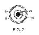
本発明の処置カテーテル10(図1)は、代表的には、近位端14、遠位端16、およびカテーテル本体内の1つ以上の管腔18、20を備える細長いカテーテル本体12を備える。遠位端16は、必要に応じて、処置の間に小葉を隔離し、かつ処置の間に残渣排出経路を提供し、そして塞栓副作用から血管系を保護するためにカテーテル本体12の遠位端から遠位方向に延びる吸引ハウジング22(図4および5)を備え得る。エネルギー伝達要素24(例えば、駆動シャフト、ワイヤ配線、またはガイドワイヤ−超音波伝達要素など)は、上記細長い本体12中の管腔の1つ内に位置決めされ得、そして、代表的には、カテーテルの近位端から遠位端まで延びる。ハンドル26は、この細長いカテーテル本体12の近位端14に連結される。発生器(例えば、RF電源、超音波発生器、モーター、光学的エネルギー供給源など)が、このハンドルに連結され得、エネルギーを、活動する遠位端28、カテーテル本体の管腔内に配置されるエネルギー伝達要素24に送達する。本明細書中に記載されるように、遠位作業要素28は、エネルギー伝達要素24の遠位端に連結され得、大動脈弁上のカルシウム沈着へのエネルギーの送達を容易にする。(Detailed description of the invention)
(Treatment catheter design-review)
The treatment catheter 10 (FIG. 1) of the present invention typically comprises an
代表的には、本発明の処置カテーテル10は、「ワイヤ上」を標的領域まで導入されるような形態である。この処置カテーテルは、ガイドカテーテルまたはシースを通って大動脈弁に隣接して位置され得る。従って、本発明の処置カテーテルは、ガイドワイヤGWを受容するための中央のガイドワイヤ管腔20を備え得る(図2)。本発明の処置カテーテルのガイドワイヤ管腔20はまた、標的領域を灌注または吸引するために用いられ得る。例えば、図示されてはいないが、上記ハンドルは、標的小葉の灌注および/または標的領域の吸引を可能にするように1つ以上のポートを備え得る。灌注供給源および/または吸引供給源は、ポート(単数または複数)に連結され得、そして上記標的領域は、カテーテルの管腔の1つを通じて吸引され得、そして/またはカテーテルの管腔の1つを通じて灌注され得る。1つの実施形態では、灌注供給源および吸引供給源の1つは、中央ガイドワイヤ管腔(中央管腔)に連結され得、そして灌注供給源および吸引供給源の他方は、このガイドワイヤ管腔に同軸である管腔に連結され得る。しかし、いくつかの実施形態では、内側のガイドワイヤ管腔はなく、そしてガイドワイヤは、図3、4および6に示されるように、超音波導波管および回転可能な駆動シャフトを通って延びる。 Typically, the
上記で注記したように、本発明の処置カテーテル10は、拡大形態および退却形態を有し、そして処置されるべき弁小葉に一致するような形態であるカテーテル本体の遠位端に位置決めされる吸引ハウジングを備え得る。この吸引ハウジング22は、この遠位端に固定して取り付けられ得るけれども、好ましい実施形態では、この吸引ハウジングは、退却形態(図3)と拡大形態(図4および5)との間を移動可能である。別個のシースがまた、この吸引ハウジングを剥き出すために退却し、そしてこのハウジングを折り畳むために進行し得る。この吸引ハウジングは、シリコーンまたはウレタンから作製され得、そして内部フレームまたはメッシュ補強で補強され得、構造的支持を提供するか、または弁小葉の特定領域上のハウジングの配置を増強する。このハウジングは、本明細書で後に詳述するように塞栓フィルターとしてさらに作用し得る。 As noted above, the
図4の実施形態では、エネルギー伝達要素24は、カテーテル本体12の遠位端を超え、そして吸引ハウジング22中に進行される。ガイドワイヤGWが、遠位先端部中の開口部を通って位置決めされる。図5中ように、一旦、処置カテーテルが標的領域に位置決めされると、ガイドワイヤGWが引き抜かれ、そして遠位作業要素28が石灰化を処置する使用のために準備が整う。 In the embodiment of FIG. 4, the
図6では、吸引ハウジング22は、二尖弁小葉の形状に実質的に一致するような形状である。この吸引ハウジングを小葉の形状に一致するように形状化することにより、この吸引ハウジングは、標的小葉を隔離するためにより良好な形態であり得る。その他の実施形態では、この吸引ハウジングは、三尖弁(図7および8)などに実質的に一致するような形状であり得る。 In FIG. 6, the
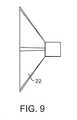
この吸引ハウジングの深さは、処置されるべき弁と適合するような多くの形態をとり得る。例えば、この吸引ハウジング22は、浅く(図9)または深く(図10)あり得る。カップに関する深さは、処置下の小葉の1つが冠状動脈小葉である場合、冠状動脈口を妨害することを減少または無くし得る。 The depth of the suction housing can take many forms to be compatible with the valve to be treated. For example, the
吸引カップ/ハウジングはまた、このハウジングの周縁または周縁の一部の周りに剛直性または半剛直性部材を有し得、輪のような特定の弁の特徴上にカップを優先的に整列する。吸引カップハウジングは、0.1インチから0.5インチまでの範囲の深さ、および15mm〜30mmの直径を有する。このカップまたはハウジングは、図11、12、および13に示されるように、フィンガー30または長軸方向安定化要素32を有し得、弁に対してハウジングを配置することを支援する。 The suction cup / housing may also have a rigid or semi-rigid member around the periphery or part of the periphery of the housing to preferentially align the cup on a particular valve feature such as a ring. The suction cup housing has a depth ranging from 0.1 inch to 0.5 inch and a diameter of 15 mm to 30 mm. The cup or housing may have
このような安定化要素はまた、プリーツ、リングまたは半球形要素、またはその他の補強物の形態であり得、上記デバイスを、弁の輪内または小葉に対して静止するために支援する。このような補強物または安定化要素は、ステンレス鋼、NiTi(超弾性または形状記憶処理)、Elgiloy(登録商標)、コバルトクロム、種々のポリマーから形成され得るか、または膨張可能な環状カップの形態であり得る。本発明のカップまたはハウジングは、塞栓事象をまた最小にしながら、上記作業要素を安定化または局在化するように処置領域との十分な接近を提供するように機能することが意図される。その意味で、それは、処置領域に対して実質的にシールしているが、このようなシールは、必ずしも「気密」シールではないが、その接近は、上記に列挙した所望の機能を行う。 Such stabilizing elements may also be in the form of pleats, rings or hemispherical elements, or other reinforcements, which assist the device to rest within the valve annulus or leaflets. Such reinforcements or stabilizing elements can be formed from stainless steel, NiTi (superelastic or shape memory treatment), Elgiloy®, cobalt chrome, various polymers, or in the form of an expandable annular cup It can be. The cup or housing of the present invention is intended to function to provide sufficient access to the treatment area to stabilize or localize the working element while also minimizing embolic events. In that sense, it is substantially sealed against the treatment area, but such a seal is not necessarily an “airtight” seal, but its access performs the desired functions listed above.
さらに、特定の安定化デバイス36、38が、主カテーテルシャフト12上に位置され得、大動脈内の安定化を提供し、そしていくつかの場合には、図14に示されるように、弁の下の弁小葉Lを通って延び、処置デバイスをさらに安定化する。 In addition,
小葉ごと、および患者ごとに種々の小葉の幾何学的形状(例えば、サイズ、湾曲)があるので、処置されるべき特定の幾何学的形状に依存して、それを通って種々のサイズおよび形状のカップまたはハウジングが通過し得る主処置カテーテルを提供することが所望され得る。例えば、システムは、図15に描写されるような処置領域上に配置された主ガイドカテーテルGCを含み得:処置領域(小葉)は、冠状動脈小葉(CL)、非冠状動脈小葉(NCL)および非冠状動脈小葉(中央)(NCLC)を含む。図16の下に示されるように、一旦、ガイドカテーテルGCがその場にあると、NCLに一致するように適合された遠位ハウジング42を有する第1の処置カテーテル40が、矢印S1によって示されるように進行される。小葉が処置され、そしてNCLハウジングカテーテルは、S2によって示されるように引き抜かれる。カイドカテーテル位置は、次いで、矢印S3によって示されるようにCLにより良好に接近するように調節され得る。CLハウジングカテーテルは、矢印S4によって示されるようにガイドを通って進行される。一旦、CL位置が処置されると、CLハウジングカテーテルは、矢印S5によって示されるように除去される。図17にさらに描写されるように、ガイドカテーテルGCは、次いでNCLCを処置するために、矢印S6によって示されるように再位置決めされ、そして最後にNCLCハウジングカテーテルが、矢印S7に従って、ガイドを通って進行される。一旦、処置が終了すると、NCLCが矢印S8によって示されるように除去され、そしてガイドが除去され、そして手順は終了する。 There are different leaflet geometries (eg, size, curvature) from leaflet to patient and from patient to patient, depending on the particular geometry to be treated, various sizes and shapes therethrough. It may be desirable to provide a main treatment catheter through which a cup or housing can pass. For example, the system may include a main guide catheter GC positioned over the treatment area as depicted in FIG. 15: the treatment area (lobule) includes coronary artery leaflets (CL), non-coronary artery leaflets (NCL) and Includes non-coronary lobule (middle) (NCLC). As shown at the bottom of FIG. 16, once the guide catheter GC is in place, a
標的とされた領域を処置するために、任意の順序でこれらのステップの任意の1つを用いることは本発明の範囲内であり、例えば、石灰化のタイプ、患者の健康、標的領域の幾何学的形状または操作者の選択に従って、1つの小葉のみが、1つ以上の小葉が、そして任意の順序で処置され得る。 It is within the scope of the present invention to use any one of these steps in any order to treat the targeted area, for example, calcification type, patient health, target area geometry. Only one leaflet can be treated, and one or more leaflets, and in any order, according to the geometry or operator choice.
(超音波処置カテーテル)
本発明の1つの局面によれば、処置カテーテル50は、小葉を脱石灰化するための超音波プローブを有して提供される。超音波プローブ52は、フレームまたはシース54によって取り囲まれ得る。フレームおよびシースの両方は、超音波振動の供給源(図示されず)に連結され得る。特定の実施形態では、このプローブ52はシースまたはハウジングによって取り囲まれ、これは、システムが、このカテーテルシステムの近位端に取り付けられ、そしてカテーテル本体中の吸引管腔を経由してカテーテルハウジングに連結される吸引の供給源を経由して処置表面に対して実質的にシールされることを可能にする。あるいは、このシステムは、処置領域(輪または小葉)に上記ハウジングを物理的に取り付ける機械的クリップまたはインターフェースで処置部位に配置または局在化され得る。操作において、この超音波プローブ52は、小葉上のカルシウムを分解するために能動化され、次いでカテーテル本体50中の吸引管腔を通って除去され得る残渣を生成する。いくつかの場合には、吸引の付与と同時またはその前にハウジング領域中に生理食塩水またはその他の流体をまた注入することが所望され得る。同様に超音波導波管に、そしてデバイスの遠位端にPZTスタックを備えるようなその他の実施形態に、冷却流体を提供することが有利であり得る。弁の部位に抗石灰化療法を注入することがまた有利であり得、鉄塩および/もしくは錫塩、または、小葉をなめすため、もしくはそうでなければカルシウム増強に対して抵抗性にする公知のようなその他の溶液を含み、これには、その内容が本明細書中に明示して援用される米国特許第5,782,931号に提示されるタイプのものがある。シリコーンカップを有する超音波プローブ60の別の実施形態が図19に示され、ここでは、注入液が矢印62によって示され、そして吸入が矢印64によって示される。(Ultrasound treatment catheter)
According to one aspect of the present invention, a
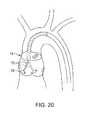
フィルターデバイス74が主カテーテルシャフト上に配置される実施形態(図20に示される)では、超音波プローブ70は別個の要素であり得、超音波処置カテーテル72がシールされた領域内で独立に移動することを可能にする。処置プローブ70は、種々の方向およびパターンで作動され得、これらは、明細書中でさらに詳述され、各小葉の尖頭に沿って円形パターンで掃引すること、および、必要であれば、全小葉を有効に処置するための処置の間に同心円を生成することを含む。フィルターデバイスの不在下では、上記超音波要素は、吸引ハウジングと同軸であり得、そしてその中で独立に動くように適合される。 In embodiments where the
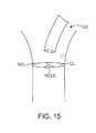
図21に示されるように、本発明の別の実施形態によれば、処置カテーテル80は、一連のガイドカテーテル82、84を通って配置され得、配置正確さを支援する。第1のガイド部材84は、大動脈根中に、大動脈壁に対して係留するためのこのガイドの形状、または別個のバルーンまたはフィルターデバイスのいずれかを用いて配置および係留され得、形状記憶材料もしくはカテーテルが処置部位に向けられるようにするための安定化を提供し得るその他の適切な材料から作製されるガイドもしくは安定化リングを安定化する。第2の操縦可能または関節運動可能なカテーテル82が、次いで、初期ガイドを通って配置され得、処置カテーテルを小葉の1つの領域またはその他に向ける。この処置カテーテル80は、次いで、一旦これらのガイドがその場にあると、上記システムを通って配置され得、そして標的とされた弁領域に直接展開される。1つの小葉を一度に処置する方法の場合には、操縦可能なガイドは、次いで、次の処置位置を標的にするために作動され得、それによって、処置カテーテル(そして関連するフィルター処理デバイス)を次の部位に向ける。処置カテーテルの前に1つのガイドカテーテルを配置することのみが必要であり得るか、またはその代わりに、この処置カテーテルは操縦可能であり得、それが、その他のガイドカテーテルの支援なしに処置部位に直接配置されることを可能にする。ガイドカテーテルはまた操縦可能であり得、そして処置カテーテルの組み込まれた一部であり得る。米国特許公開第2004/0092962号および同第2004/0044350号中に描写されるような操縦可能なガイドが例であり、それらの内容は、その全体が参考として明示して援用される。処置デバイスは、次いで、図22中に示されるように、第2の処置部位に再方向付けされ得る。 As shown in FIG. 21, according to another embodiment of the present invention, a
本発明の処置カテーテルの遠位部分90は、標的とされる小葉Lの形状に実質的に対応する形状であり得る(例えば、図23に示されるような小葉形状に一致するような形状であるハウジングの口とともに、小葉尖頭の形状内に適合するような形状)。これはまた、小葉の表面を処置のために安定化されるようにする。遠位部分は、展開および処置の間に遠位セクションを支持するが、それが処置カテーテルまたはシース中に折り畳まれ引き抜きを支援するように可撓性である内部フレームを有し得る。 The
あるいは、本発明の処置カテーテル100は、処置されるべき輪にエネルギー/振動を付与するために周縁の輪処置102を有して形成され得る。この実施形態では、カテーテルは、順行性または逆行性で配置され得るか、または図24に示されるように、2つの周縁処置面が、互いと組み合わされて用いられ得る。 Alternatively, the
種々の超音波仕事端部が、処置されるべき疾患のタイプおよび位置に依存して用いられ得る。例えば、超音波カテーテルの遠位先端部は、超音波伝達部材または導波管に連結され得る。この遠位先端部は、以下の種々の例から選択され得、鈍い先端部、面取り先端部、丸められた先端部、尖った先端部を含み、そしてさらに、この先端部の表面から突出し、カルシウムの崩壊を増大する節(ノジュール)またはリブをさらに含み得る(図25C)。矢印は、例示の使用のパターンを示す。 Various ultrasonic work edges can be used depending on the type and location of the disease to be treated. For example, the distal tip of the ultrasound catheter can be coupled to an ultrasound transmission member or waveguide. The distal tip may be selected from the following various examples, including a blunt tip, a chamfered tip, a rounded tip, a pointed tip, and further protruding from the surface of the tip, It may further include nodules or ribs that increase the collapse of (Fig. 25C). The arrows indicate exemplary usage patterns.
本発明の超音波カテーテルの遠位先端部はまた、その内容が本明細書中に参考として明示して援用される米国特許第5,304,115号中に示され、そして記載される導波管先端部の形状をとり得る。その内容が本明細書中に参考として明示して援用される米国特許第5,989,208号(「Nita」)は、図2〜7A中に、弁小葉を脱石灰化するために有用であり得るさらなるいくつかの先端部を示す。 The distal tip of the ultrasonic catheter of the present invention is also shown in and described in US Pat. No. 5,304,115, the contents of which are expressly incorporated herein by reference. It can take the shape of the tube tip. US Pat. No. 5,989,208 (“Nita”), the contents of which are expressly incorporated herein by reference, is useful for demineralizing valve leaflets in FIGS. 2-7A. Some further tips are possible.
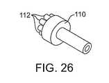
本発明の超音波伝達部材は、拡大された遠位仕事端部に連結される中実チューブを備え得る。中央管腔は、超音波伝達部材全体を通じて延び、そして吸入、吸引のために、そして/またはガイドワイヤを受容するために用いられ得る。図26、27および28に示される実施形態では、拡大された仕事端部110(これは、細長い近位部分より大きな直径を有する)は、複数の細長い部材112を備える円筒形部分を備え得る。例示の形態では、これら細長い部材は、城のようなパターンで整列され(例えば、これら細長い部材の各々が遠位方向に延びる円形パターン)、そして超音波伝達部材の長軸方向軸に沿って開口部を提供する。これら細長い部材は、円筒形の形状であるが、その他の実施形態では、これら細長い部材は、丸められ得るか、鋭いか、などであり得る。 The ultrasonic transmission member of the present invention may comprise a solid tube coupled to the enlarged distal work end. The central lumen extends throughout the ultrasound transmission member and can be used for inhalation, aspiration, and / or for receiving a guidewire. In the embodiment shown in FIGS. 26, 27 and 28, the enlarged work end 110 (which has a larger diameter than the elongate proximal portion) may comprise a cylindrical portion comprising a plurality of
遠位仕事端部のさらなる実施形態では、上記に示した実施形態と同様に、中央管腔が、超音波伝達要素を通り、そして拡大遠位仕事端部を通って延び得る。図29、30および31に示される形態では、この遠位仕事端部120は、拡大され、かつ丸められている。 In further embodiments of the distal work end, the central lumen may extend through the ultrasound transmission element and through the enlarged distal work end, similar to the embodiment shown above. In the configuration shown in FIGS. 29, 30 and 31, the
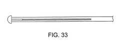
代替の実施形態では、遠位仕事端部に隣接している超音波伝達部材(または導波管)の部分は、この仕事端部からの超音波の送達を増幅するように改変され得る。導波管は、管材中に複数の軸方向スロットを含み得、これはこの管材から複数の「細いワイヤ」を生成するように作用し、これは、超音波の波が軸方向よりはむしろ半径方向に移動するようにする。拡大された遠位仕事端部は、次いで、複数の細いワイヤに取り付けられ得る。このような形態の2つの実施形態は、図32および33中に示される。代替の実施形態では、各城造りは、デバイスの近位端に戻って延びるそれ自体のシャフト上に収容され得る。その他の可能な先端部の幾何学的形状は以下に描写される。 In an alternative embodiment, the portion of the ultrasound transmission member (or waveguide) adjacent to the distal work end may be modified to amplify the delivery of ultrasound from this work end. A waveguide may include a plurality of axial slots in the tube, which acts to generate a plurality of “thin wires” from the tube, which causes the ultrasonic wave to be radiused rather than axial. To move in the direction. The enlarged distal work end can then be attached to a plurality of thin wires. Two embodiments of such configuration are shown in FIGS. 32 and 33. In an alternative embodiment, each castle structure may be housed on its own shaft that extends back to the proximal end of the device. Other possible tip geometries are depicted below.
本発明の超音波カテーテルは、振動性、点描性、円形、側生またはそれらの任意の組み合わせである遠位先端部に動きを付与するように適合され得る。本明細書中に記載される任意のこのような遠位先端部について、出願人らは、カテーテル本体の内径に対して小さな遠位先端部の使用がより良好な大きさの運動を提供し、そして改良された脱石灰化を提供し得ることを見出した。さらに、本発明の超音波先端部は、とりわけ、処置されている小葉または輪の領域に依存して、種々の処置パターンで作動され得る。例えば、この処置パターンは、使用者によって制御されるか、処置デバイス中にプログラムされるかのいずれかであり、1つの小葉または領域が一度に処置されるとき、処置されている表面上の脱石灰化のリングを提供するような円形運動、カルシウムのより大きな沈着物を破壊する交差ハッチングパターン(図24)、または半球形(図36)もしくは、くさび形状(図37)パターンであり得る。列挙されたパターンの任意の組み合わせを用いること、またはよりランダムなパターンを採用すること、または単に直線運動は、本発明の範囲内である。 The ultrasonic catheter of the present invention can be adapted to impart motion to the distal tip that is vibratory, stippling, circular, lateral, or any combination thereof. For any such distal tip described herein, Applicants provide better sized movement with the use of a small distal tip relative to the inner diameter of the catheter body; And it has been found that improved demineralization can be provided. Furthermore, the ultrasound tip of the present invention can be actuated in various treatment patterns, depending, inter alia, on the area of the leaflet or ring being treated. For example, this treatment pattern is either controlled by the user or programmed into the treatment device, and when one leaflet or region is treated at a time, the treatment pattern is removed from the surface being treated. It can be a circular motion to provide a ring of calcification, a cross-hatching pattern that destroys larger deposits of calcium (FIG. 24), or a hemispherical (FIG. 36) or wedge shaped (FIG. 37) pattern. It is within the scope of the present invention to use any combination of the listed patterns, or to employ a more random pattern, or simply linear motion.
特定の安全機構が、処置カテーテル上および関連する構成要素上に取り込まれ得、処置デバイスが小葉を穿孔しないか、またはそうでなければ小葉を劣化しないことを確実にする。1つの実施形態では、力制限特徴が、図38に示されるように処置カテーテルシャフト中に組み込まれ得、ここで、構造物140が、矢印144の方向でカテーテル142に付与された力に応答して接触し得る。 Certain safety features can be incorporated on the treatment catheter and on associated components to ensure that the treatment device does not puncture the leaflets or otherwise degrade the leaflets. In one embodiment, a force limiting feature may be incorporated into the treatment catheter shaft as shown in FIG. 38 where the
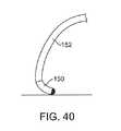
別の実施形態では、カテーテルシャフトの特徴が、組織に送達される力を制限し得る。比較的剛直性のカテーテルシャフト152上の軟遠位先端部150(図39)では、図40に示されるように力は、この先端部を偏向し得る。 In another embodiment, the characteristics of the catheter shaft may limit the force delivered to the tissue. For the soft distal tip 150 (FIG. 39) on the relatively
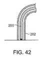
さらに、処置カテーテル200は、図41および42に示されるように処置カテーテルへの深さ制限器として作用するシース202を通って進行され得る。これらの種々の安全特徴は、採用されるエネルギーにかかわらず、本発明の処置デバイスのいずれにも組み込まれ得る。 Further, the
本発明の超音波カテーテルのアセンブリが図43中に示され、超音波伝達部材210、伝達ヘッド212、ガイドワイヤGW、吸引カップ214、スプリング216、およびカテーテル本体218を含む。 The ultrasonic catheter assembly of the present invention is shown in FIG. 43 and includes an
超音波カテーテル220の別の実施形態は、図44に示されるように、PZTスタック222および遠位ホーン224を含む。 Another embodiment of the
図44の実施形態の利点は、それが、長い導波管および長い導波管を用いるとき生じる損失をなくすることである。この実施形態では、吸引ハウジングは、PZTスタックおよび超音波ホーン上に適合し得る。特定の有用な超音波要素は、Briskenによる米国特許第5,725,494号、Zaleskyにより同第5,069,664号、Carterによる同第5,269,291号および同第5,318,014号に描写され、それらの内容は、それらの全体が参考として明示して援用される。 The advantage of the embodiment of FIG. 44 is that it eliminates the losses that occur when using long waveguides and long waveguides. In this embodiment, the suction housing can fit over the PZT stack and the ultrasonic horn. Certain useful ultrasonic elements are US Pat. No. 5,725,494 by Brisken, US Pat. No. 5,069,664 by Zalesky, US Pat. Nos. 5,269,291 and 5,318,014 by Carter. And their contents are expressly incorporated by reference in their entirety.
本発明の超音波カテーテルの近位端は、図45に描写された概略に従って構成され得る。近位ハウジング232上のノブ230は、デバイスの遠位端に連結される制御ワイヤに連結される。これらのノブは、これら制御ワイヤを引っ張るように作動し、それによって遠位端の角度を操作する。ギア、ピン、およびシャフトのような、操縦可能なガイドのための制御234は、制御ボックス236中に収容され、このボックスの上にノブが位置される。処置デバイスの主本体は、外側シャフトおよびスライドノブに連結される内側シャフトをさらに備える。順に、この内側シャフトは、デバイスの遠位端でハウジングに、上記スライドノブが退却されるとき、ハウジングが退却位置から拡大位置に転置するように作動可能に連結され、その逆も同じである。図45にされに描写されるのは、駆動コイルに運動を与えるために、エネルギー供給源またはプライム移動器に作動可能に連結されている駆動シャフトまたは駆動コイル230である。駆動コイルは、デバイスの遠位端中、処置されるべき組織に接触する作業要素で終わる。あるいは、超音波を利用する設計では、超音波導波管または伝達要素が、外側シャフトおよび/または内側シャフト内に位置決めされ得る。 The proximal end of the ultrasonic catheter of the present invention may be configured according to the schematic depicted in FIG. A
(機械的処理カテーテルおよび方法)
上記に記載の超音波処置カテーテルに加え、本発明は、小葉上のカルシウムを機械的に破壊または除去するために能動化可能な先端部を用いる処置カテーテルおよび方法をさらに提供する。一般に、これらカテーテルは、1つ以上の管腔を備えるカテーテル本体を備える。駆動シャフト(または類似の要素)が、これら管腔の1つの近位端から、この管腔の遠位端まで延び得る。遠位作業要素は、この駆動シャフトに連結され(またはそれから一体に形成され)得、そしてカテーテル本体の遠位端を少なくとも部分的に超えて延びるような形態である。この駆動シャフトの近位端は、機械的運動(回転、振動および/まは軸方向移動)の供給源に連結され得、駆動シャフトおよび遠位作業要素を駆動する。(Mechanical processing catheter and method)
In addition to the ultrasonic treatment catheter described above, the present invention further provides a treatment catheter and method that uses an activatable tip to mechanically destroy or remove calcium on the leaflets. In general, these catheters comprise a catheter body comprising one or more lumens. A drive shaft (or similar element) may extend from one proximal end of the lumens to the distal end of the lumens. The distal working element can be coupled to (or integrally formed with) the drive shaft and is configured to extend at least partially beyond the distal end of the catheter body. The proximal end of the drive shaft can be coupled to a source of mechanical motion (rotation, vibration and / or axial movement) to drive the drive shaft and the distal working element.
本発明のカテーテルは、小葉を脱石灰化するために種々の形態を用い得る。用いられ得るこれらの作業要素およびカテーテル本体の遠位端のいくつかの例は、以下に説明される。 The catheters of the present invention can use a variety of configurations to demineralize the leaflets. Some examples of these working elements that can be used and the distal end of the catheter body are described below.
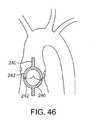
1つの実施形態(図46)では、カテーテル240の遠位端は、脱石灰化されている小葉と接触そして/または隔離するために用いられ得る吸引ハウジング242を備える。この吸引ハウジングは、漏斗形状要素として示されているが、代替の実施形態では、この吸引ハウジングは、(上記に記載のように)処置されるべきである小葉と類似の形状であり得る。この吸引ハウジング242は、カテーテル本体240の遠位端に固定して連結され得るか、または、それは、遠位端部分に移動可能に連結され得る。このような移動可能な実施形態では、この吸引ハウジングは、この吸引ハウジングがカテーテル本体の管腔内に少なくとも部分的に配置される退却位置(示されず)から、拡大形態(以下に示す)まで移動され得る。あるいは、機械的クリップ、クランプまたはその他の固定要素が、以下に描写されるような処置されるべき輪または小葉に処置デバイスを局在化するために用いられ得、小葉を固定するために逆行性方向および順行性方向から配置される要素を含む。 In one embodiment (FIG. 46), the distal end of the
図47の形態では、遠位作業要素は、回転可能な偏心的に負荷されるコイル250を備え得る。このコイルの遠位部分は、遠位方向にテーパー状であり得、そしてその遠位端または遠位端の近傍にボール252(またはその他の形状の要素)を備え得る。必要に応じて、1つ以上の秤量要素(示されず)がコイルの種々の部分に沿って連結され得、コイルの振動の動力学を変える。認識され得るように、この重量がコイルの長軸方向軸から離れて位置決めされると、コイルの回転プロフィールは変化する。結果として、1つ以上の重量の戦略的配置は、単純回転からコイルの振動を、軸方向振動成分もまた有するコイルに変更し得る。 In the form of FIG. 47, the distal working element may comprise a rotatable eccentrically loaded
別の実施形態(図48)では、作業要素は、偏心して負荷された非テーパー状コイル260を備え得る。このコイルは、その遠位端にボールまたは重量を備えても良いし、または備えなくても良い。 In another embodiment (FIG. 48), the working element may comprise an eccentrically loaded
なお別の実施形態(図49)は、遠位コイルは、細長い遠位ワイヤ先端部270を備え得、そこでは、少なくとも一部分が、遠位コイル作業要素の外径を超えて半径方向に延びる。示されるように、この遠位ワイヤ先端部は、1つ(またはそれ以上)のボールまたは重量を備え得る。この遠位ワイヤ先端部は、湾曲、真っ直ぐ、またはそれらの組み合わせであり得る。前述の遠位コイルの代替として(またはこれに加え)、遠位作業要素は、石灰化に接触し、そして小葉からこの石灰化を機械的に除去するような形態である「ドリルビット」型インペラーまたはDremel型振動または回転部材を遠位先端部に備え得る。認識され得るように、このような実施形態は、非超音波範囲の作動で、そして代表的には10Hz〜20,000Hz、好ましくは100Hz〜1000Hzで、回転および振動される。このような形態では、形状のあるインペラーの回転は、代表的には、カテーテル本体中の管腔に向かって近位方向に移動される石灰化残渣を生じる。いくつかの実施形態では、このインペラーは、小葉にある程度の保護を提供するように丸められたエッジを備え得る。上記に記載の実施形態の各々では、シースが回転する要素を覆い得、保護を提供するか、または、このシースを通じて回転移動および軸方向移動を伝達することにより方向付けられた力を提供する。 In yet another embodiment (FIG. 49), the distal coil may comprise an elongated
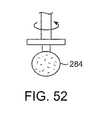
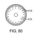
上記作業要素はまた、機械的に回転するデバイスを備え得る。図50の実施形態では、卵形形状のバール(かえり、burr)280が、その配向が、デバイスの中央軸(回転軸)との垂直の整列から、デバイスの中央軸から90゜以上までの範囲で示される。この軸を離れる配向は、所定範囲の創面切除位置可能にし、そして弁の輪内に偏心して位置される狭窄、またはデバイスの中心軸に対して角度をなしている小葉表面を処置するような特定の状況により適用可能であり得る。処置デバイスの中央軸に対する処置先端部の角度付けは、先端部領域における増加した速度を提供することにより石灰化の断片化を容易にする。類似の配列が図51に示されるが、異なる形状で、より細長いバール282である。さらに、図52は、ディスクの面に穴を有するディスクの形態にあるバール要素284を示し、このバール要素を通る残渣の排出を可能にする。任意の機械的作業要素が、粗くされた表面、カーバイド先端部材料、またはダイヤモンド被覆を有し得、標的とされた材料の断片化を増大することが本発明の範囲内である。代表的なバール要素は、Ditec Manufacturing(Carpenteria、CA)、Diamond Tool(Provedence、RI)、およびCarbide Grinding Co.(Waukesha、WI)のようないくつかの会社によって製造されている。 The working element may also comprise a mechanically rotating device. In the embodiment of FIG. 50, the
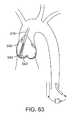
代替の方法では、第動脈弁に近接して、そして小葉に実際に接触せずにインペラー要素を位置決めすることが可能であり得る(図53)。このインペラーの回転は、渦動を引き起こし得、小葉から離れ、そして吸引ハウジングおよびカテーテル本体中に石灰性物質を除去する。このインペラーは、その内容が、本明細書中に参考として明示して援用されるKenseyによる米国特許第4,747,821号に記載されるインペラーのような種々の形状をとり得る。 In an alternative method, it may be possible to position the impeller element in proximity to the second arterial valve and without actually touching the leaflets (FIG. 53). This impeller rotation can cause vorticity, leaves the leaflets and removes calcareous material into the suction housing and catheter body. The impeller may take various forms, such as the impeller described in US Pat. No. 4,747,821 by Kensey, the contents of which are expressly incorporated herein by reference.
別の形態では、回転するグラインダーヘッド292(図54)が、遠位コイル294に連結され得る。この回転するグラインダー遠位先端部は、種々の形状をとり得る。以下に示される形態では、このグラインダー遠位先端部は、凸状形状であり、そして駆動シャフトの軸方向管腔と連通している中央開口部の周りの半径方向円形パターンにある複数の穴を備える。このような形態では、このグラインダー遠位先端部は、遠位コイルおよび駆動シャフトの残りの長軸方向軸の周りに対称的に位置決めされる。半径方向の開口は、粒子の灌注および吸引を可能にする。いくつかの形態では、このグラインダー遠位先端部は、ダイヤモンドダストのような研磨材料を備え得、大動脈弁から石灰性物質の除去を支援する。 In another form, a rotating grinder head 292 (FIG. 54) can be coupled to the
図55および56に示される別のグラインダー遠位先端部形態では、このグラインダー遠位先端部は、平坦なプレート300を備え得る。この平坦なグラインダー遠位先端部は、研磨材料、穴、および/または機械加工突出部またはナブを備え得る。このような要素は、小葉からの石灰化除去を促進するために用いられ得る。 In another grinder distal tip configuration shown in FIGS. 55 and 56, the grinder distal tip can comprise a
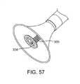
図57に示されるような代替の形態では、グラインダー遠位先端部304は、遠位コイル306の周りに偏心して取り付けられ得、回転に際し、このグラインダー先端部は、グラインダー遠位先端部のサイズを拡大する必要性なくして小葉のより大きな断面積を覆い得る。以下の図は、平坦なグラインダー遠位先端部を示すが、本明細書中に記載される任意の遠位先端部は、遠位端コイルと偏心して取り付けられ得ることが認識されるべきである。 In an alternative form as shown in FIG. 57, the grinder
別の実施形態では、遠位作業要素は、超音波作業要素について上記で示されたような、城造りの機械的先端部を備え得る。必要に応じて、この城造り先端部は、この遠位先端部から後方に設置されるインペラーを有し得る。 In another embodiment, the distal working element may comprise a castle-shaped mechanical tip, as indicated above for the ultrasonic working element. If desired, the castle tip may have an impeller installed rearward from the distal tip.
なお別の実施形態では、本発明は、小葉を脱石灰化するために、その全体の開示が参考として本明細書中に明示して援用される、米国特許第5,314、407号または同第6,818,001号に記載されるRotablatorデバイスを使用し得る。このRotablatorデバイス(以下に示される)は、当初記載されるように用いられ得るか、または遠位先端部は、この先端部を平坦化することにより、この先端部上にダイヤモンドダストを付与することにより、この遠位先端部をより球根状にすることよりなどによって改変され得る。上記「407特許」からとられる図58を参照のこと。 In yet another embodiment, the present invention relates to US Pat. No. 5,314,407 or the same, the entire disclosure of which is expressly incorporated herein by reference to demineralize the leaflets. The Rotator device described in 6,818,001 may be used. The Rotator device (shown below) can be used as initially described, or the distal tip can impart diamond dust on the tip by flattening the tip. Can be modified, such as by making the distal tip more bulbous. See FIG. 58 taken from the “407 Patent” above.
このRotablatorのために用いられる空気タービンは、前述の機械によることを基礎にする処置カテーテルのいくつか、またはすべてに動力を与えるために用いられ得る。この空気タービンは、小葉上のカルシウムの破壊のために適切な大きさのトルクおよび速度を提供する。本発明の駆動シャフトと遠位先端部の低い慣性モーメントと組み合わせたこのトルクと速度とは、災害的駆動シャフト破損のリスクを減少する。例えば、遠位先端部が、石灰性沈着物と接触に起因して「負荷される」ようになるとき、回転の速度は、駆動シャフトにかみつく(スナップする)ことなく、またはそれを壊すことなくゼロまで減少する。この空気タービンの代替物として、モーターが適切な時間にスローダウンされ得るようにトルクおよび速度を感知し得る電子的フィードバックシステムを備えたモーターを用いることもまた可能であり得る。 The air turbine used for this Rotator can be used to power some or all of the mechanical catheters described above. This air turbine provides the appropriate amount of torque and speed for the destruction of calcium on the leaflets. This torque and speed combined with the drive shaft of the present invention and the low moment of inertia of the distal tip reduces the risk of catastrophic drive shaft failure. For example, when the distal tip becomes “loaded” due to contact with calcareous deposits, the speed of rotation does not snap to the drive shaft or break it Decrease to zero. As an alternative to this air turbine, it may also be possible to use a motor with an electronic feedback system that can sense torque and speed so that the motor can be slowed down at the appropriate time.
上記処置カテーテルのいくつかの実施形態は、遠位作業要素を取り囲む随意のシースを備え得る。図59に示されるように、このシースは、この遠位作業要素を取り囲む球形形状の遠位先端部310を備え得る。細長い近位部分は、この球形の遠位先端部に取り付けられ、そしてカテーテル本体の管腔内にある駆動シャフトのいくらか、またはすべてを覆うようなサイズおよび形状である。この球形形状の遠位先端部は、媒体(例えば、対比媒体、冷却剤など)の送達および/またはガイドワイヤの通路を可能にし得る開口部312を備え得る。上記機械的要素または超音波伝達要素は、シースの先端部を超えて延び得る。類似の描写は、Nashによる米国特許第6,843,797号中に示され、その開示は、本明細書中に明示して援用される。 Some embodiments of the treatment catheter may include an optional sheath surrounding the distal working element. As shown in FIG. 59, the sheath may include a spherically shaped
いくつかの実施形態では、上記シースは、シースの端部が偏向し、延び、そして/または退却することを可能にする、ふいごまたは可撓性部分を備え得る。このシースは、代表的には回転せず、そしてこのシースは、代表的には、上記遠位作業要素および駆動シャフトがこのシース内で回転することを可能にするサイズである。この遠位作業要素のシース内の回転は、シースを関節運動させ(これは、駆動シャフトの作動の形状およびタイプに依存する)、そして石灰化沈着物に対する「擦り洗う効果」を生成し得る。有利なことに、このシースは、駆動シャフトの機械的運動を伝達し、その一方、上記作業要素の振動を制御することにより小葉に対する保護の層を提供する。このシースは、当該技術分野で公知の種々の材料から作製され、そして上記球形遠位先端部内の遠位作業要素の回転からの摩擦に耐えるような様式で補強される。結果として、このシースのための1つの有用な材料は、スチールであるか、または編組まれたか、もしくはその他のカテーテル補強技法である。 In some embodiments, the sheath may comprise a bellows or flexible portion that allows the end of the sheath to deflect, extend, and / or retract. The sheath typically does not rotate, and the sheath is typically sized to allow the distal working element and drive shaft to rotate within the sheath. This rotation in the sheath of the distal working element can articulate the sheath (which depends on the shape and type of actuation of the drive shaft) and can create a “scrubbing effect” on the calcified deposit. Advantageously, this sheath transmits the mechanical movement of the drive shaft, while providing a layer of protection against the leaflets by controlling the vibration of the working element. The sheath is made from a variety of materials known in the art and reinforced in a manner that resists friction from rotation of the distal working element within the spherical distal tip. As a result, one useful material for this sheath is steel or braided or other catheter reinforcement techniques.
任意の機械的実施形態では、組織によって、観察される熱エネルギーを減少し、そして壊死組織切除の間の残渣の除去を支援し得る冷却流体を循環または注入することが所望され得る。このような流体はまた、超音波実施形態または機械的実施形態のいずれかでキャビテーション効果を提供することによって組織断片化を支援し得る。 In any mechanical embodiment, it may be desirable for the tissue to circulate or inject a cooling fluid that can reduce the observed thermal energy and assist in the removal of debris during debridement. Such fluids may also assist tissue fragmentation by providing a cavitation effect in either the ultrasonic or mechanical embodiment.
(マイクロスフェアおよび/またはマイクロバブルの実質的な使用)
上記のように、超音波処置カテーテルおよび機械的処置カテーテルの大部分の実施形態は、カテーテル本体を通ってその遠位端まである管腔を備える。冷却流体、超音波造影流体などのような媒体を管腔を通って標的小葉に送達し、小葉上の包埋された石灰化の塊へのエネルギー送達の影響を増幅することが有用であり得る。1つの好ましい形態では、この媒体は、マイクロスフェアまたはマイクロバブルを含み得る。本発明の方法および処置カテーテルと用いられ得る1つの有用な造影媒体は、OptisonTM造影剤(GE Healthcare)である。治療効果を増大するためのキャビテーションおよび/またはマイクロバブルを利用する技法の種々の描写は、Tachibanaによる米国特許第USRE036939号、およびBen−Haimによる同第6,321,109号中に見出され得、その内容は、それらの全体が本明細書中に参考として明示して援用される。(Substantial use of microspheres and / or microbubbles)
As noted above, most embodiments of ultrasonic and mechanical treatment catheters include a lumen that extends through the catheter body to its distal end. It may be useful to deliver a medium such as a cooling fluid, ultrasound contrast fluid, etc. through the lumen to the target leaflet to amplify the effect of energy delivery to the embedded calcified mass on the leaflet. . In one preferred form, the medium can include microspheres or microbubbles. One useful contrast medium that can be used with the methods and treatment catheters of the present invention is the Optison™ contrast agent (GE Healthcare). Various depictions of techniques utilizing cavitation and / or microbubbles to increase therapeutic efficacy can be found in US Patent No. USRE0369939 by Tachibana and US Pat. No. 6,321,109 by Ben-Haim. The contents of which are expressly incorporated herein by reference in their entirety.
マイクロバブルを含む造営媒体を通る超音波の波の送達は、小葉に送達されるキャビテーションまたは断片化エネルギーの量を増大し得る。この手順の間に吸引を付与することはまた、CiminoおよびBond、「組織断片化を用いる超音波手術の物理学:第I部および第II部」、Ultrasound in Medicine and Biology、22巻、第1号、89〜100頁、および101〜117頁、1996によって記載されるように断片化エネルギーを増大し得る。ガス本体(例えば、マイクロバブル)の超音波パルスとの相互作用は、非熱摂動(例えば、キャビテーションに関連する機械的現象)を増大する。従って、マイクロバブルとともに制御された量の造影剤を用いることは、小葉からの石灰化の除去を増大し得る。マイクロバブルの超音波エネルギーとの使用のより完全な記載は、Guzmanら、「音響キャビテーション泡密度および細胞濃度における変化によって引き起こされた生体効果:細胞−対−泡の比および芽細胞半径に基づく統合化された説明」、Ultrasound in Med.&Biol.、29巻、第8号、1211〜1222頁、およびMillerら、「造影剤ガス本体の診断超音波活性化による類表皮および食細胞単層の溶解およびソノポレーション」、Ultrasound in Med.&Biol.27巻、第8号、1107〜1113頁、2001に記載され、これらの全体の開示は、本明細書中に参考として援用される。 Delivery of ultrasonic waves through a construction medium containing microbubbles can increase the amount of cavitation or fragmentation energy delivered to the leaflets. Giving suction during this procedure is also described in Cimino and Bond, “Physics of Ultrasound Surgery with Tissue Fragmentation: Part I and Part II”, Ultrasound in Medicine and Biology, Vol. 22, Part 1 No. 89-100, and 101-117, 1996 may increase the fragmentation energy. Interaction of the gas body (eg, microbubbles) with the ultrasonic pulses increases non-thermal perturbations (eg, mechanical phenomena associated with cavitation). Thus, using a controlled amount of contrast agent with microbubbles can increase the removal of calcification from the leaflets. A more complete description of the use of microbubbles with ultrasonic energy can be found in Guzman et al., “Bioeffects caused by changes in acoustic cavitation bubble density and cell concentration: integration based on cell-to-bubble ratio and blast radius. Generalized description ", Ultrasound in Med. & Biol. 29, No. 8, pp. 1211-1222, and Miller et al., “Dissolution and Sonoporation of Epidermis and Phagocytic Monolayers by Diagnostic Ultrasound Activation of the Contrast Gas Body”, Ultrasound in Med. & Biol. 27, No. 8, pages 1107 to 1113, 2001, the entire disclosures of which are incorporated herein by reference.
しかし、マイクロバブルの使用は、超音波または機械的処置カテーテルに制限されないことが認識されるべきである。例えば、以下に示されるように、RFカテーテル実施形態において、カテーテル本体は、カテーテルの遠位端または遠位端近傍に位置決めされる2つのRF電極を備え得る。マイクロバブルをともなう媒体は、カテーテルの管腔を通って標的小葉に送達され得、そしてRFエネルギーが2の配線間に送達され得、エネルギーをマイクロバブルに送達する。いくつかの実施形態では、マイクロバブルの使用なくして小葉上の石灰化にRFエネルギーを送達することが所望され得る。その他の実施形態では、その他のタイプのエネルギー供給源を用いることが所望され得、小葉にエネルギーを送達する。 However, it should be appreciated that the use of microbubbles is not limited to ultrasound or mechanical treatment catheters. For example, as shown below, in an RF catheter embodiment, the catheter body may comprise two RF electrodes positioned at or near the distal end of the catheter. Media with microbubbles can be delivered to the target leaflet through the lumen of the catheter, and RF energy can be delivered between the two wires, delivering energy to the microbubbles. In some embodiments, it may be desirable to deliver RF energy to calcification on the leaflets without the use of microbubbles. In other embodiments, it may be desirable to use other types of energy sources to deliver energy to the leaflets.
RF電極の代替物として、カテーテルの遠位先端部に圧電フィルム330を位置決めすることが可能である(図60)。ワイヤ配線は、カテーテル本体の管腔を通り、その中(または外側)を延び得、そして電源に連結され得る。ワイヤ配線がカテーテル本体の管腔内に配置される場合、このカテーテルは、ワイヤを絶縁するための内側チューブを備え得る。媒体は、カテーテル本体の内側管腔を通って送達され得、そしてこのカテーテル本体の遠位端で圧電フィルムに曝され、そしてエネルギーは、圧電フィルムから、そしてマイクロバブルをともなう媒体中に送達され得る。 As an alternative to the RF electrode, the
(保護)
本発明のさらなる局面では、保護デバイスおよび方法が、処置部位から残渣を捕捉および排出するために用いられ得る。図61および62に示される実施形態では、フィルターデバイス336が、ガイドカテーテル338のシャフト上に位置される。この構造はまた、大動脈根中にガイドカテーテルの係留を提供し、弁への安定な接近システム、またはさらなる処置カテーテルを配置することを提供する。(protection)
In a further aspect of the invention, the protection device and method can be used to capture and drain residues from the treatment site. In the embodiment shown in FIGS. 61 and 62, the
別の実施形態(図63)では、フィルターデバイスが、処置の全体領域を保護するために提供され、そして血液および吸引物が、濾過された血管系の動脈側から除去され、静脈循環中の戻して注入するような全身フィルター装置340を含み得、さらに詳細は、Parodiによる米国特許第6,423,032号中に記載され、その開示は、本明細書中に明示して援用される。吸引ポート342が、カテーテル346の遠位端で超音波プローブ344を取り囲む。 In another embodiment (FIG. 63), a filter device is provided to protect the entire area of treatment, and blood and aspirate are removed from the arterial side of the filtered vasculature and returned in venous circulation. And a full
処置部位により局所的に緊密に(例えば、一度に1つの小葉)付与される濾過を有し、大動脈弁のすぐ上に位置する冠状動脈の口のような局所的構造を保護することが有利であり得る。このような濾過装置は、図64中に示される超音波吸引カテーテルのような処置デバイスと組み合わせて用いられ得、ここでは、フィルターデバイス350が、吸引ポート354で超音波プローブ352によって係合される単一の小葉を覆う。さらに、このフィルターの形状は、図6に示されるように、最も関連のある小葉または処置部位に接近するために最適化され得る。上記の濾過または保護システムのいずれもは、本明細書中に開示される任意の処置カテーテルと用いられ得る。 It would be advantageous to have a filtration applied locally tightly (eg, one leaflet at a time) by the treatment site to protect local structures such as the mouth of the coronary artery located just above the aortic valve possible. Such a filtration device can be used in combination with a treatment device such as the ultrasonic aspiration catheter shown in FIG. 64 where the
本発明の多くの特徴は、処置されるべき疾患の部位で最適に処置カテーテルを方向付け、位置決めし、そして安定化することを支援する。カテーテルおよびガイド特徴に加え、弁内に静止するバスケット、アンカーまたはフィルター形態が、カテーテルを位置決めするために用いられ得る。例えば、心臓は、ペースをとる配線に連結され得、そして心臓は、次に、増加した速度、例えば、1分間あたり200拍動のペースにされ、これは、次に、血流を阻止する比較的固定された位置に大動脈小葉を保持し、そして本発明の処置カテーテルが、少なくとも1つの小葉に適用されることを可能にする。吸引ハウジンクのようなカテーテルの配置の後、ペースどりは停止され、そして残りの小葉は、カテーテルによって係合されず、正常に機能する。すべての小葉が一度に係合される事例では、灌流バルーンまたは当該技術分野で公知のデバイスにおけるような、処置カテーテルを通る流れを提供することが必要であり得、そのいくつかの特徴は、Goldbergによる米国特許第4,909,252号中に示され、その開示は、本明細書中に参考として明示して援用される。 Many features of the present invention assist in optimally directing, positioning and stabilizing the treatment catheter at the site of the disease to be treated. In addition to the catheter and guide features, a basket, anchor or filter configuration that rests within the valve can be used to position the catheter. For example, the heart can be coupled to paced wiring and the heart is then brought to an increased rate, eg, 200 beats per minute, which is then compared to block blood flow Holding the aortic leaflet in a fixed position and allowing the treatment catheter of the present invention to be applied to at least one leaflet. After placement of the catheter, such as a suction housing, the pacemaker is stopped and the remaining leaflets are not engaged by the catheter and function normally. In the case where all the leaflets are engaged at once, it may be necessary to provide flow through the treatment catheter, such as in a perfusion balloon or device known in the art, some of which features Goldberg U.S. Pat. No. 4,909,252, the disclosure of which is expressly incorporated herein by reference.
(撮像法)
本発明の特徴は、手順の前、その間、およびその後のモニタリングおよび撮像のための種々のデバイスおよび方法を含む。種々の撮像診断様式が、この目的のために採用され得、心臓内超音波心臓検査法(ICE)、経食道超音波心臓図検査(TEE)、蛍光透視、血管内超音波(IVUS)、血管顕微鏡検査、赤外、Sensant,Inc./Seimens(San Leandro、CA)から入手可能な容量性超音波トランスデューサー(cMUT)または当該分野で公知のその他の手段を含む。例えば、処置カテーテルは、位相アレイ血管内超音波要素のような、ハウジングまたは処置要素カテーテル中に組み込まれる撮像デバイスを有し得る。いくつかの実施形態では、本発明のデバイスを、それらの作動要素が、シースと同軸である別個で取り外し可能な要素であるように構築することが有利であり得、操作者が作業要素を取り外し、そしてその場所に撮像要素を配置する。(Imaging method)
Features of the present invention include various devices and methods for monitoring and imaging before, during, and after the procedure. Various imaging diagnostic modalities can be employed for this purpose: intracardiac echocardiography (ICE), transesophageal echocardiography (TEE), fluoroscopy, intravascular ultrasound (IVUS), blood vessels Microscopy, Infrared, Sensant, Inc. / Capacitive ultrasound transducer (cMUT) available from Seimens (San Leandro, CA) or other means known in the art. For example, a treatment catheter may have an imaging device that is incorporated into a housing or treatment element catheter, such as a phased array intravascular ultrasound element. In some embodiments, it may be advantageous to construct the devices of the present invention such that their actuating elements are separate and removable elements that are coaxial with the sheath, allowing the operator to remove the working element. , And arrange the imaging element at that location.
撮像は、疾患のタイプおよび位置を診断すること、処置カテーテルを配置すること、処置プロセスを評価すること、および一旦処置されたなら弁の機能を確認することを含む手順の種々のステージで重要になり得る。撮像デバイスは、カテーテル先端部、もしくはカテーテル本体、処置カテーテルと平行して、または当該技術分野で公知のようなより遠隔の位置(例えば、上大静脈、食道、または右心房)のような処置部位に局所的に配置され得る。撮像要素が処置カテーテル上に配置される場合、それは、「前方を見ること」、例えば、処置デバイスの前の平面または複数平面中の撮像であるように適合され得る。 Imaging is important at various stages of the procedure, including diagnosing the type and location of the disease, placing a treatment catheter, evaluating the treatment process, and confirming the function of the valve once it has been treated Can be. The imaging device may be a treatment site, such as a catheter tip, or catheter body, parallel to a treatment catheter, or a more remote location as known in the art (eg, superior vena cava, esophagus, or right atrium). Can be placed locally. When the imaging element is placed on the treatment catheter, it can be adapted to “look forward”, eg imaging in a plane or planes in front of the treatment device.
呼び掛け(インターロゲーション)技法、またはその他の撮像様式を採用することがまた本発明の範囲内である。例えば、処置部位の直接可視化のために血液を透視するための赤外撮像、またはエラストグラフィー、組織運動の超音波測定、どのタイプの組織が標的であるかを感知すること、例えば、小葉組織またはカルシウム、または最も石灰化でされている弁の領域を感知することである。この文脈におけるエラストグラフィーは、その内容が本明細書中に参考として明示して援用される、「Characterization of plaque components and vulnerability with intravascular ultrasound elastography」、Phys.Med.Biol.45(2000)、1465〜1475に記載されるような、機械的トランスデューサーまたは位相アレイシステムのいずれかである、血管内超音波(IVUS)カテーテルを用いて実施され得る。実際、このトランスデューサーは、弁上の処置部位に、そして外部から付与された力、あるいは外部から付与され力もしくは(弁小葉の開放および閉鎖のような)組織自身中の自然に起こる運動いずれかによる組織領域の「周期的興奮」のいずれかを用いて進行され得、初期ベースライン読み取り値がとられ得る。このベースラインは、本発明の吸引カテーテル(処置部位内で循環する流体を含む)で処置されるべき領域または小葉を係合すること、この処置カテーテルを通って処置部位まで超音波トランスデューサーを挿入すること、およびこの超音波トランスデューサーで標的とされた領域に呼び掛け領域の弾性(ストレス/歪みプロフィール)を確立することによって設定され得る。小葉の特定領域について、注入が次いで停止され、(吸引単独により)小葉をさらなるストレス下に置き、そしてこのストレス/歪みプロフィールにおける位置ずれが記録および評価され、処置デバイスをより少ない弾性を示すような領域(カルシウム沈着物の存在を示す「より剛直性の」領域。本明細書中に参考として明示して援用される「エラストグラフィー−動きが開始する」Phys.Med.Biol.45(2000)1409〜1421および「生物学的組織の弾性性質を撮像するために選択された方法」Annu.Rev.Biomed.Eng.(2003)5:57〜78に提示されるような技法をまた参照のこと)に向ける。 It is also within the scope of the present invention to employ interrogation techniques or other imaging modalities. For example, infrared imaging to see through the blood for direct visualization of the treatment site, or elastography, ultrasonic measurement of tissue motion, sensing which type of tissue is the target, eg, leaflet tissue or Sense the area of the valve that is calcium, or most calcified. Elastography in this context is described in “Characterization of plaque components and vulnerability with intravascular ultrasound”, the contents of which are expressly incorporated herein by reference. Med. Biol. 45 (2000), 1465-1475, which can be performed using an intravascular ultrasound (IVUS) catheter that is either a mechanical transducer or a phased array system. In fact, this transducer can either apply force applied externally to the treatment site on the valve, or force applied externally or naturally occurring movements in the tissue itself (such as the opening and closing of valve leaflets). Can be progressed using any of the “periodic excitement” of the tissue region, and an initial baseline reading can be taken. This baseline engages an area or leaflet to be treated with the suction catheter of the present invention (including fluid circulating within the treatment site) and inserts an ultrasonic transducer through the treatment catheter to the treatment site. And by setting the elasticity (stress / strain profile) of the interrogation area to the area targeted by this ultrasonic transducer. For a particular area of the leaflet, the injection is then stopped, the leaflet is placed under further stress (by suction alone), and misalignment in this stress / strain profile is recorded and evaluated, indicating that the treatment device exhibits less elasticity Region (“Stiffer” region indicating the presence of calcific deposits. “Elastography-motion begins” Phys. Med. Biol. 45 (2000) 1409, expressly incorporated herein by reference. -1421 and "Methods Selected for Imaging the Elastic Properties of Biological Tissue" Annu. Rev. Biomed. Eng. (2003) 5: 57-78 also see techniques) Turn to.
いくつかの例では、例えば、超音波またはレーザーとともに、上記領域に呼び掛けまたは撮像するために用いられるのと同じトランスデューサーまたは光ファイバーがまた、下にあるカルシウム沈着物を分解または処置するために用いられ得る。特定のパラメーターが、治療デバイスを診断から治療に遷移するために調節され得、周波数、電力、送達される全エネルギーなどを含む。 In some examples, the same transducer or optical fiber used to interrogate or image the area, for example, with ultrasound or laser is also used to degrade or treat the underlying calcium deposits. obtain. Certain parameters can be adjusted to transition the treatment device from diagnosis to treatment, including frequency, power, total energy delivered, and the like.
さらに、その他の特徴付け技法が、処置されるべき石灰化領域を標的にするため、または処置の結果を評価するための両方で採用され得、MRI、Doppler、および抵抗性データ、インピーダンス/インダクタンスフィードバックなどを利用する技法を含む。記載のような撮像およびその他のモニタリング技法を用いることは、カルシウム沈着物を除去することに焦点をあてたより標的とする手順を生じ得、そして所望されない増殖応答に至り得る小葉および輪への可能な組織損傷を制限する。 In addition, other characterization techniques can be employed both to target the calcified area to be treated or to evaluate the outcome of the treatment, MRI, Doppler, and resistive data, impedance / inductance feedback Including techniques that use Using imaging and other monitoring techniques as described can result in a more targeted procedure focused on removing calcific deposits and possible to leaflets and rings that can lead to unwanted proliferative responses Limit tissue damage.
(処置のエネルギー供給源/方法)
種々のエネルギー様式が、本発明によって想定される処置カテーテルで用いられ得る。カルシウム沈着物を分解または除去するためにより詳細に有用な様式は、超音波エネルギー、レーザーエネルギーなどであり得る。特に、特定のEr:YAGレーザーが、適切な範囲で作動されるとき、カルシウムを特異的に標的とし得る。これを支持する標的とされる骨切除する特定の詳細は、「Er:YAGレーザーおよびCO2レーザーを用いる骨除去の走査電子顕微鏡法およびFourier変換赤外分光法分析」J Periodontol.2002年6月;73(6):643〜52に記載され、その内容は、本明細書中に参考として明示して援用される。あるいは、エネルギーは、高エネルギーパルス化または走査型二酸化炭素レーザー、短パルス化Er:YAG、および調節(短−および−長−パルス化)Er:YAGシステムのような、制御された組織蒸発を生じる水を含有する組織を選択的に標的とする表面付け替えレーザーを採用することにより、カルシウム沈着物の周り、またはその上から組織を選択的に除去するために送達され得る。エネルギーの付与は、小葉間に分布されるプラークまたはカルシウム(海綿体)に接近するために有用であり得る。実際、大部分の小葉が無傷で残り、そして不必要な熱損傷からシールドされるように沈着物を覆う組織の層を除去することが所望され得る。さらに、このような特定組織破壊はまた、本発明の処置の一部として弁の輪内の瘢痕組織または肥大の領域の除去に適用され得る。(Energy source / method of treatment)
Various energy modalities can be used with the treatment catheter envisioned by the present invention. More particularly useful modes for decomposing or removing calcium deposits can be ultrasonic energy, laser energy, and the like. In particular, certain Er: YAG lasers can specifically target calcium when operated in the appropriate range. Specific details of targeted osteotomy in support of this are described in “Scanning Electron Microscopy and Fourier Transform Infrared Spectroscopy Analysis of Bone Removal Using Er: YAG Laser and CO2 Laser” J Periodontol. 2002 June; 73 (6): 643-52, the contents of which are expressly incorporated herein by reference. Alternatively, the energy results in controlled tissue evaporation, such as high energy pulsed or scanning carbon dioxide lasers, short pulsed Er: YAG, and regulated (short-and-long-pulsed) Er: YAG systems. By employing a resurfacing laser that selectively targets tissue containing water, it can be delivered to selectively remove tissue around or on the calcific deposit. The application of energy can be useful to gain access to plaque or calcium (caverns) distributed between the leaflets. In fact, it may be desirable to remove a layer of tissue covering the deposit so that most of the leaflets remain intact and shielded from unnecessary thermal damage. Furthermore, such specific tissue destruction can also be applied to the removal of scar tissue or hypertrophied areas within the valve annulus as part of the procedure of the present invention.
本発明の超音波処置カテーテルは、10〜200ミクロンの範囲、例えば、75〜150ミクロンの振動速度(20〜400ミクロン間の最大行程)で、5〜100kHz間の範囲、例えば、10〜50kHzで作動され得る。さらに、熱損傷またはその他の組織損傷の可能性を最小にするため、5〜50%の衝撃係数、例えば、5〜20%の衝撃係数のようなパルス化様式で上記処置デバイスを作動することが有利であり得、最も病気の領域にエネルギー送達を注意深く標的とすることによってこのエネルギー付与に曝される組織を最少にする。 The ultrasonic treatment catheter of the present invention is in the range of 10-200 microns, such as 75-150 microns, with a vibration speed (maximum stroke between 20-400 microns), in the range of 5-100 kHz, such as 10-50 kHz. Can be actuated. Furthermore, the treatment device can be operated in a pulsed manner such as an impact factor of 5-50%, for example an impact factor of 5-20%, in order to minimize the possibility of thermal damage or other tissue damage. It can be advantageous to minimize the tissue exposed to this energy application by carefully targeting energy delivery to the most diseased areas.
さらに、病気の弁の特定の位置上の処置に焦点をあてることが有利であり得、この場所で、カルシウム沈着物を除去すること、または減少することが、最大量の回復された小葉様相および得られる弁機能を生じる。例えば、小葉の中央セクション内の小葉の天頂で、または交連にある弁の輪内の沈着物が、最初に標的とされ得る。弁にともなうこれらの種々の位置の概略描写は、図66、67、および68に描写され、ここで、図67および68は、図66の線A−AおよびB−Bにそれぞれ沿った断面である。 In addition, it may be advantageous to focus on treatment on a specific location of the diseased valve, where removal or reduction of calcific deposits is the maximum amount of recovered leaflet features and The resulting valve function is produced. For example, deposits at the leaflet zenith in the central section of the leaflet or in the valve ring in commissure may be initially targeted. A schematic depiction of these various positions with the valve is depicted in FIGS. 66, 67, and 68, where FIGS. 67 and 68 are cross-sections along lines AA and BB, respectively, in FIG. is there.
用いられるエネルギーのタイプおよび周波数に依存して、本発明の処置カテーテルはまた、カルシウムを除去するのみならず、Andersonによる米国特許第5,840,081号および同第6,582,462号、Wilsonによる米国特許出願第2004/0092858号、KhairkhahanによるWO2004/093728、HermannによるWO2005/009285などに記載のような、最少侵襲的補綴具弁の移植のために調製におけるように、小葉自体を除去または取り除くために利用され得、これらの開示は、本明細書中に参考として明示して援用される。本発明のデバイスでの前処理は、このような補綴具弁の配置を容易にし得る。なぜなら、移植の部位からカルシウムを除去することは、弁周囲の漏れ、取り外れを減少し得、そして増加した有効弁オリフィスに起因して移植されているより大きな補綴具を生じ得るからである。 Depending on the type and frequency of energy used, the treatment catheter of the present invention not only removes calcium, but also Anderson US Pat. Nos. 5,840,081 and 6,582,462, Wilson. The leaflets themselves are removed or removed as in preparation for implantation of minimally invasive prosthetic valve, such as described in US Patent Application No. 2004/0092858 by Kairkhahan, WO 2004/093728 by Herman, WO 2005/009285 by Hermann, etc. The disclosures of which are expressly incorporated herein by reference. Pretreatment with the device of the present invention may facilitate the placement of such prosthetic valve. This is because removing calcium from the site of implantation can reduce peri-valve leakage, detachment, and can result in a larger prosthesis being implanted due to the increased effective valve orifice.
(移植可能なデバイス)
一旦修復が達成されると、除去される上記のデバイスの代替物または付属物として、大動脈弁を横切って、または大動脈弁内に一時的または永久的に移植されるデバイスが提供され得る。以下に出現するデバイスは、再石灰化、小葉の融合、および再狭窄のいずれかにより、弁が変性することを防ぐか、または遅延するために、狭窄が終了した後に、身体内で少なくとも所定の時間の間残ることがすべて意図される。本発明のインプラントは、輪の下360または輪の上の位置362いずれかで図67に描写される。(Portable device)
Once repair is achieved, a device that can be temporarily or permanently implanted across or within the aortic valve as an alternative or appendage of the above-described device to be removed. The devices that appear below are at least pre-determined in the body after the stenosis has ended to prevent or delay the valve from degeneration, either by remineralization, leaflet fusion, and restenosis. All intended to remain for hours. The implant of the present invention is depicted in FIG. 67 at either the lower 360 of the annulus or the
いくつかの実施形態では、以下に描写されるコイルのようなインプラントを配置し、輪の下および輪の上の両方に延ばし、弁へのさらなる支持を提供し、そして弁を横切るより大きな処置領域を提供することが所望され得る。この実施形態のコイル設計は、2つのリング部分を接続する単一の支柱を有するが、弁の輪のすぐ上の冠状動脈を閉塞しないように十分低プロフィールである。図68を参照のこと。その開放構造のため、インプラントの輪の上の位置は、さらなる係留のために冠状動脈の上で大動脈根に延び得る。図69を参照のこと。 In some embodiments, an implant such as a coil, described below, is placed, extends both below and above the annulus, provides further support to the valve, and a larger treatment area across the valve It may be desirable to provide The coil design of this embodiment has a single strut connecting the two ring sections, but has a low enough profile so as not to occlude the coronary artery just above the valve annulus. See FIG. Due to its open structure, the position on the ring of the implant can extend over the coronary artery to the aortic root for further anchoring. See FIG.
さらなる実施形態において、上記インプラントは、ワイヤ、一連のワイヤ、または周縁ステントまたは冠状動脈ステントで用いられるのと類似であるセル構造から形成される。弁の輪中、または弁の下により良好に静止するために、弁の尖頭に正弦形態で従うようにイプラントリングを形成することが有利であり得る。さらに、このインプラントリングは、弁の輪に対して静止するように延びる支柱を有し得、構造物を提供するか、または特定の弁部位で薬学的被覆をさらに広める。図70、71、および72を参照のこと。 In a further embodiment, the implant is formed from a wire, a series of wires, or a cellular structure similar to that used in peripheral or coronary stents. In order to better rest in the valve annulus or under the valve, it may be advantageous to form an implant ring to follow the valve tip in a sinusoidal fashion. In addition, the implant ring may have struts that extend to rest relative to the valve annulus, providing a structure or further spreading the pharmaceutical coating at a particular valve site. See FIGS. 70, 71, and 72.
なお別の実施形態では、上記インプラントは、互いから120゜の3つのループ120のような複数のループから形成され得る。図73〜76を参照のこと。 In yet another embodiment, the implant may be formed from a plurality of loops, such as three
この実施形態、およびワイヤ形態を描写するその他において、ワイヤは、所望の力に依存して0.020インチと0.250インチとの間の直径を有し得る。さらに、ワイヤは平坦であり得、そして構造物は、ループ間にメッシュを含み得、弁を支持するため、または薬学的薬剤の送達のためのより大きな表面積を提供する。このデバイスのループは、周期的様式で遠位方向および近位方向に移動され得、弁小葉をさらに開放し、そして単独治療としてプラークを破壊する。このデバイスは、次いで、上記のように永久的に移植され得る。一旦、弁が治療されたなら、または適正な配置を確実にするために永久的なインプラントの位置決めの間に、デバイスを再捕獲することが所望され得る。再捕獲デバイスは、それからインプラントが展開される送達カテーテルであり得るか、または回収カテーテルの遠位端上の拡大可能な漏斗を含み得るか、またはインプラント上のフックと嵌合するグラスパーまたはフックを含む任意の数の機械的デバイスを含み得るか、またはインプラントが送達シース中に引かれ得、そして身体から除去され得るように特定の点でインプランを握る。 In this embodiment, and others depicting wire configurations, the wire may have a diameter between 0.020 inches and 0.250 inches depending on the desired force. Further, the wire can be flat and the structure can include a mesh between the loops to provide a larger surface area to support the valve or for delivery of a pharmaceutical agent. The loop of the device can be moved in the distal and proximal directions in a periodic manner to further open the valve leaflets and destroy the plaque as a monotherapy. This device can then be permanently implanted as described above. It may be desirable to recapture the device once the valve has been treated, or during permanent implant positioning to ensure proper placement. The recapture device can be a delivery catheter from which the implant is deployed, can include an expandable funnel on the distal end of the retrieval catheter, or can include a glass spar or hook that mates with a hook on the implant Any number of mechanical devices can be included, or the implant can be pulled into the delivery sheath and held in place at a particular point so that it can be removed from the body.
本明細書中に記載される任意のインプントの構造は、当該分野で公知であるような手順評価の目的のために、それらを放射線不透過性またはエコー発生性にする表面増強または被覆を有し得る。冠状動脈ステント処理の分野でさらに公知であるように、記載されるデバイスは、永久的、除去可能、または生腐食性であり得る。それらは、デバイス中またはデバイス上に設計される、被覆、穴、デポー、ポアまたは表面不規則性の形態にある、上記で提示されるような抗再狭窄薬剤または材料を取り込み得る。さらに、上記インプラントは、その内容が本明細書中に明示して援用される米国特許第6,254,635号中に提示されるような特定の石灰化抵抗性材料から形成され得る。さらに、本発明のインプラントは、僅かな電気的荷電を発するような形態であり得る。カルシウムは正に荷電されるので、大動脈インプラントの表面を正に荷電することによりカルシウムを反発することが有利であり得る。さらに、電気的エネルギーがインプラントによって供給され得、本明細書中に参考として明示して援用される米国特許第6,505,080号中に記載されるような移植可能なペースメーカータイプのデバイスによって石灰化を最少にする。 The structure of any of the implants described herein has surface enhancements or coatings that make them radiopaque or echogenic for purposes of procedural evaluation as is known in the art. obtain. As is further known in the field of coronary stenting, the devices described can be permanent, removable, or bioerodible. They can incorporate anti-restenosis agents or materials as presented above in the form of coatings, holes, depots, pores or surface irregularities designed in or on the device. Further, the implant may be formed from a specific calcification resistant material as presented in US Pat. No. 6,254,635, the contents of which are expressly incorporated herein. Furthermore, the implant of the present invention may be configured to emit a slight electrical charge. Since calcium is positively charged, it may be advantageous to repel calcium by positively charging the surface of the aortic implant. In addition, electrical energy can be supplied by the implant and lime by an implantable pacemaker type device as described in US Pat. No. 6,505,080, expressly incorporated herein by reference. Minimization.
さらに、特定の機械的手順およびインプラントを、先に列挙されたような種々の適切な薬学的薬剤と組み合わせることが本発明の範囲内である。この適用に有用であり得る抗再狭窄薬剤は、当該技術分野で公知の任意のファミリーの薬剤またはエネルギー様式から選択され得る。例えば、ラパマイシン、パクリタキセル、シロリムスまたは窒素酸化物促進剤のような薬学的薬剤またはそれらのアナログが、意図的に生成された表面不規則性、または穴もしくは芝生(ディボット)のような特定の表面特徴中に取り込まれる溶出性被覆を用いてこれらのデバイス上に被覆され得る。上記デバイスは、本発明の手順を実施するために利用されるインプラントに上記薬剤を接着するために、被覆またはその他の表面の取り込みによる薬剤注入のために設計され得るか、または本発明の手順に従う口腔投与のために処方され得る。例えば、本発明の処置に従い、患者は、所定用量のスタチン、ACEインヒビター、または上記介入によって提供される弁機能を延長するためのその他の薬剤を処方され得る。 Furthermore, it is within the scope of the present invention to combine specific mechanical procedures and implants with various suitable pharmaceutical agents as listed above. Anti-restenotic agents that may be useful for this application may be selected from any family of agents or energy modalities known in the art. For example, pharmaceutical agents such as rapamycin, paclitaxel, sirolimus or nitrogen oxide promoters or analogs thereof are intentionally generated surface irregularities or specific surface features such as holes or lawn (divot) These devices can be coated with an eluting coating incorporated therein. The device may be designed for drug injection by coating or other surface incorporation to adhere the drug to an implant utilized to carry out the procedure of the invention, or according to the procedure of the invention It can be formulated for buccal administration. For example, in accordance with the treatment of the present invention, the patient can be prescribed a predetermined dose of statins, ACE inhibitors, or other agents to prolong the valve function provided by the intervention.
図77〜89は、急性または亜慢性手順のために意図されたシステムの種々の実施形態を提示する。これらのデバイスは、大動脈弁を横切って配置され得、そして再拡大されて大動脈弁を再開放し、そして次に所定の時間の間処置された弁を、修復を容易にし、そして/または再狭窄を防ぐために設計された抗再狭窄薬剤またはエネルギー様式に曝すためにその場に残る。図77および78に示されるデバイスは、外方に延び、交連で融合された小葉を係合および分離する機械的羽根(ベーン)400を特徴とする。これらの羽根は、任意の適切な金属、プラスチックまたは組み合わせから作製され得る。それらは、自己拡大性であるか(例えば、ニチノールまたはエルジロイから作製される)、またはそれらは、空気力、水力、ねじ、またはその他の機械的作動システムを用いて機械的に作動され得る。これらの羽根は、上記に示されるような変形可能な部材であり得るか、または各羽根は、ヒンジ部分で連結されたいくつかのより剛直性のパーツから構成され得、このユニットの拡大および退却を可能にする。上記の羽根は、融合された小葉の分離を容易にするよう、そして弁が閉鎖される場合にその能力に衝撃を与えることなく交連内に適合するように設計されたより狭いエッジを備えた、形状が矩形である断面を備えて設計され得る。これらの矩形の羽根のより広い面は、小葉の新たに分離されたエッジと接触し得る。この矩形の断面の代替物として、これらの羽根は、いっそう多くの翼形状またはその他の断面形状を有するように設計され得、血流内の乱流を最少にし、そして弁の小葉に対する外傷を最少にする。 77-89 present various embodiments of a system intended for acute or subchronic procedures. These devices can be placed across the aortic valve and re-expanded to reopen the aortic valve and then facilitate the repair and / or restenosis of the valve that has been treated for a predetermined time Stay in place to be exposed to anti-restenotic drugs or energy modalities designed to prevent. The devices shown in FIGS. 77 and 78 feature
図79および80のデバイスは、本発明の方法に従って用いられるバルーンシステムを示す。このバルーン410は、以下により詳細に記載されるような抗再狭窄薬剤の注入のために用いられる複数の穴412を特徴とし得る。これらの穴は、注入されるべき薬剤のわずかな滲出のみを可能にするに十分小さくあり得るか、またはそれらは、より迅速な注入またはより大きな容量の注入液が送達されることを可能にし得るサイズであり得る。これらの穴は、バルーンの周縁の周りに均一な分布で配置され得るか、またはそれらは、交連の位置とより直接的に整列するように配置され得る。 The device of FIGS. 79 and 80 shows a balloon system used in accordance with the method of the present invention. The
図81および82のデバイスは、図77および78の特徴を、79および80のそれらと組み合わせるバルーンシステムを備える。いくつかのバルーンは、各バルーンが交連424と整列するように配置される。このデバイスの膨張は、心臓から、そしてこのデバイスがその場にある身体中への連続した灌流を可能にし得る。これは、次に、抗再狭窄薬剤のより持続する送達のために少なくあり得る。穴が、図79および80中のデバイス上の穴についての説明と同様に図3のバルーン上に配置され得る。 The device of FIGS. 81 and 82 comprises a balloon system that combines the features of FIGS. 77 and 78 with those of 79 and 80. Several balloons are positioned such that each balloon is aligned with
本出願で有用であり得る抗再狭窄薬剤は、当該技術分野で公知の任意のファミリーの薬剤またはエネルギー様式から選択され得る。例えば、ラパマイシン、パクリタキセル、シロリムスまたは酸化窒素促進薬剤のような薬学的薬剤またはそれらのアナログが、意図的に生成された表面不規則性、または穴もしくは芝生(ディボット)のような特定の表面特徴中に取り込まれる溶出性被覆を用いて任意の本発明のデバイス上に被覆され得る。記載されるように、これらデバイスは、図面に示されるようなバルーンまたは交連切開羽根のようなデバイスの仕事実施要素中の注入チャネルおよび注入穴の取り込みによる薬物注入のために設計され得る。 Anti-restenotic agents that may be useful in the present application may be selected from any family of agents or energy modalities known in the art. For example, pharmaceutical agents such as rapamycin, paclitaxel, sirolimus or nitric oxide promoting agents or analogs thereof are intentionally generated surface irregularities, or in certain surface features such as holes or lawn (divot) It can be coated on any of the devices of the invention using an elution coating incorporated into the device. As described, these devices can be designed for drug injection by the incorporation of injection channels and injection holes in the device's work performing elements such as balloons or commissure blades as shown in the drawings.
エネルギー送達は、いくつかの異なる様式によって、そして異なる目的のために達成され得る。高周波エネルギーは、交連切開羽根にエネルギーを与えることにより、または湿潤電極を達成するためのバルーン上の穴を用いることにより付与され得る。マイクロ波、超音波、高周波超音波エネルギー、またはパルス化電場(細胞のエレクトロポーレーションを誘導する目的のため)が、アンテナまたは電極を、羽根、バルーンまたはこれらの仕事を実施する要素を支持するカテーテルシャフト中に組み込むことによって用いられ得る。寒冷療法は、上記仕事を実施する要素を通じて相変化ガスまたは液体窒素のような冷却流体を循環することによって達成され得る。複数の様式が、耐久性大動脈弁修復の目的を達成するために単一のデバイス中に組み込まれ得る。 Energy delivery can be achieved in several different ways and for different purposes. High frequency energy can be applied by energizing the commissure blades or by using a hole on the balloon to achieve a wet electrode. Microwave, ultrasound, high frequency ultrasound energy, or pulsed electric field (for the purpose of inducing cell electroporation) supports antennas or electrodes, vanes, balloons or elements that perform these tasks It can be used by incorporating it into the shaft. Cryotherapy can be achieved by circulating a cooling fluid, such as phase change gas or liquid nitrogen, through the element performing the task. Multiple modalities can be incorporated into a single device to achieve the purpose of durable aortic valve repair.
このエネルギーは、例えば、融合された小葉を分けることをより容易にすることによって弁修復を容易にするために用いられ得る。あるいは、このエネルギーは、処置された弁の再狭窄を遅延または防ぐために用いられ得る。再狭窄の予防のためのエネルギー送達の使用の1つの例は、細胞のアポトーシスを誘導するためのパルス化電場の使用である。ナノ秒の大きさの持続時間の電気のパルスの印加が細胞の細胞内装置を改変し得、そしてパクリタキセルまたはシロリムスのような臨床的に証明された抗再狭窄薬物の作用の機構の鍵となる局面であることが知られる、アポトーシス、またはプログラム化された細胞死を誘導することが知られる。 This energy can be used, for example, to facilitate valve repair by making it easier to separate fused leaflets. Alternatively, this energy can be used to delay or prevent restenosis of the treated valve. One example of the use of energy delivery for the prevention of restenosis is the use of a pulsed electric field to induce cell apoptosis. Application of electrical pulses of nanosecond duration duration can modify the intracellular device of the cell and is key to the mechanism of action of clinically proven anti-restenotic drugs such as paclitaxel or sirolimus It is known to induce apoptosis, or programmed cell death, known to be an aspect.
これらの薬剤またはエネルギーの付与は、数分〜数時間の経過に亘って、患者がカテーテル使用ラボにいる間に投与される。あるいは、上記デバイスは、患者がその場にあるデバイスとともに、薬剤の注入またはエネルギーの印加が、数時間または数日の経過に亘って進行し得るように、病院床に戻ることを可能にするように設計され得る。 These medications or energy doses are administered while the patient is in the catheterization lab over a period of minutes to hours. Alternatively, the device allows the patient to return to the hospital floor so that drug injection or application of energy can proceed over the course of hours or days with the device in place. Can be designed to.
B.一旦、修復が達成されると取り出され、そして抗再狭窄薬剤の投与が終了する上記に記載のデバイスの代替物または付属物として、大動脈弁を横切るか、またはその中に一時的または永久的に移植されるデバイスが提供され得る。以下に出現するこれらのデバイスは、すべて、狭窄の修復の終了した後、弁が互いに再接着すること、および再狭窄することを防ぐか、または遅延するために、少なくとも所定の時間の間残ることが意図される。 B. As an alternative or appendage of the above-described device, once the repair is achieved and removed and the administration of the anti-restenosis drug is terminated, traverse the aortic valve or temporarily or permanently therein A device to be implanted can be provided. All of these devices appearing below will remain for at least a predetermined time after the repair of the stenosis, to prevent or delay the valves from reattaching to each other and restenosis. Is intended.
記載されるデバイスは、永久的、取り外し可能、または生腐食性であり得る。それらは、被覆、穴、デポー、ポア、またはデバイス中もしくはデバイス上に付与されるように設計された表面不規則性中に、抗再狭窄薬剤または材料を取り込み得る。 The described device can be permanent, removable, or bioerodible. They can incorporate anti-restenosis agents or materials into coatings, holes, depots, pores, or surface irregularities that are designed to be applied in or on the device.
支柱430は、図83および84に示されるような、任意の適切な金属、プラスチックまたは組み合わせから作製され得る。それらは、自己拡大性であり得るか(例えば、ニチノールまたはエルジロイから作製される)、またはそれらは、空気力、水力、ねじまたはその他の機械的作動システムを用いて移植の間、機械的に能動化され得、そして次に、送達システムからのデバイスの展開に先立って、それらの最終位置中にロックされる。上記の支柱は、上記に示されるような変形可能な部材であり得るか、または各支柱は、ヒンジ作用部分で連結されたいくつかのより剛直性のパーツから構築され得、ユニットの拡大および収縮を可能にする。上記支柱は、融合された小葉の分離を容易にするよう、そして弁が閉鎖される場合にその能力に衝撃を与えることなく交連内に適合するように設計されたより狭いエッジを備えた、形状が矩形である断面を備えて設計され得る。これらの矩形の支柱のより広い面は、小葉の新たに分離されたエッジと接触し得る。この矩形の断面の代替物として、これらの支柱は、いっそう多くの翼形状またはその他の断面形状を有するように設計され得、血流内の乱流を最少にし、そして弁の小葉に対する外傷を最少にする。 The
図85〜89は、移植可能なデバイスについて代替の設計を示す。修復された小葉の処置された領域に長期間の抗再狭窄薬剤またはエネルギー様式を提供する目的を達成するインプラントのための任意の設計が、本発明の主題であるとして考慮されるべきである。大動脈の壁に対して横たわり、そして(図85および86におけるような)支柱と再構築する前に大動脈の中心に接続する、支柱とほぼ連続的である(図83および84に示されるような)係留要素、または支柱自体が係留要素である設計は、すべて、本発明の実施形態である。 85-89 show an alternative design for an implantable device. Any design for an implant that achieves the objective of providing a long-term anti-restenosis drug or energy modality to the treated area of the repaired leaflet should be considered as the subject of the present invention. Lying against the wall of the aorta and connected to the center of the aorta prior to reconstruction with the struts (as in FIGS. 85 and 86) (as shown in FIGS. 83 and 84) All designs where the mooring element or the post itself is the mooring element are embodiments of the present invention.
上記移植可能でかつ生腐食性デバイスは、すべて、ラパマイシン、パクリタキセル、シロリムスまたは酸化窒素増強薬剤のような薬学的薬剤またはそれらのアナログを特徴とし得、これらは、薬物溶出性被覆を用いて、または意図的に生成された表面不規則性もしくは穴もしくはデポーのような特定の表面特徴中に取り込まれ、任意の本発明のデバイス上に被覆され得る。 The implantable and bioerodible devices can all be characterized by pharmaceutical agents such as rapamycin, paclitaxel, sirolimus or nitric oxide enhancing agents or analogs thereof, using drug eluting coatings, or It can be incorporated into specific surface features such as intentionally generated surface irregularities or holes or depots and coated on any of the devices of the present invention.
さらなる抗再狭窄薬剤またはエネルギー様式が、例えば、上記送達システムの特徴として、イプラント上に取り込まれるような薬剤とは別個、そして/またはそれに加えて送達され得る。 Additional anti-restenotic agents or energy modalities can be delivered separately and / or in addition to agents such as those incorporated on an implant, for example as a feature of the delivery system.
本発明は、種々の改変、および代替形態をとり得るが、その特定の例が図面中に示され、そして本明細書中に詳細に記載される。しかし、本発明が、開示される特定の形態もしくは方法に制限されることはないことが理解されるべきであり、反対に、本発明は、本開示および添付の請求項の思想および範囲に入るすべての改変物、等価物および代替物を包含する。 While the invention may be susceptible to various modifications and alternative forms, specific examples thereof have been shown in the drawings and are herein described in detail. However, it should be understood that the invention is not limited to the particular forms or methods disclosed, but on the contrary, the invention falls within the spirit and scope of the disclosure and the appended claims. Includes all modifications, equivalents and alternatives.
Claims (9)
Translated fromJapanese近位端、遠位端およびそれらの間の管腔を備えるカテーテル本体;
該カテーテル本体の遠位端近傍の吸引ハウジングであって、該吸引ハウジングは拡大形態と退却形態との間を移動可能であり、該拡大形態は該弁の小葉に一致するような形態であり、そして該退却形態では該吸引ハウジングは該管腔内に少なくとも部分的に配置され、そして該吸引ハウジングは塞栓残渣を捕捉するための障壁を備え、該吸引ハウジングは該心臓弁上の石灰性部位の周りに一致し、血管をブロックまたは閉塞することなく該石灰性部位のすぐ上に塞栓の閉じ込め領域を生成する吸引ハウジング;および
該石灰性部位を破壊するように適合された作業要素であって、該塞栓の閉じ込め領域内に位置決め可能であり、そして該吸引ハウジングに対して関節運動可能であって、該作業要素の配置を該石灰性部位に対して調節する作業要素、を備え、
ここで、該吸引ハウジングが該作業要素を該拡大形態に安定化または局在化するように構成される、処置カテーテル。A treatment catheter for repair of a heart valve associated with a blood vessel:
A catheter body comprising a proximal end, a distal end and a lumen therebetween;
A suction housing near the distal end of the catheter body, the suction housing being movable between an expanded configuration and a retracted configuration, the expanded configuration configured to match theleaflets of the valve; And in the retracted configuration, the suction housing is at least partially disposed within the lumen, and the suction housing includes a barrier for capturing emboli debris, the suction housing comprising a calcific site on the heart valve. A suction housing that conforms around and creates an embolic confinement region immediately above the calcareous site without blocking or occluding the blood vessel; and a working element adapted to destroy the calcareous site; An operation that is positionable within the confinement region of the embolus and is articulatable with respect to the suction housing, wherein the arrangement of the working element is adjusted with respect to the calcareous site Elements,
Wherein the suction housing Ruis configured to stabilize or localized in the enlarged form the said working element, the treatment catheter.
Applications Claiming Priority (7)
| Application Number | Priority Date | Filing Date | Title |
|---|---|---|---|
| US63527504P | 2004-12-09 | 2004-12-09 | |
| US60/635,275 | 2004-12-09 | ||
| US66276405P | 2005-03-16 | 2005-03-16 | |
| US60/662,764 | 2005-03-16 | ||
| US69829705P | 2005-07-11 | 2005-07-11 | |
| US60/698,297 | 2005-07-11 | ||
| PCT/US2005/044543WO2006063199A2 (en) | 2004-12-09 | 2005-12-09 | Aortic valve repair |
Publications (3)
| Publication Number | Publication Date |
|---|---|
| JP2008522755A JP2008522755A (en) | 2008-07-03 |
| JP2008522755A5 JP2008522755A5 (en) | 2009-01-29 |
| JP5219518B2true JP5219518B2 (en) | 2013-06-26 |
Family
ID=36578602
Family Applications (1)
| Application Number | Title | Priority Date | Filing Date |
|---|---|---|---|
| JP2007545650AExpired - Fee RelatedJP5219518B2 (en) | 2004-12-09 | 2005-12-09 | Aortic valve repair |
Country Status (5)
| Country | Link |
|---|---|
| US (5) | US7803168B2 (en) |
| EP (1) | EP1819304B1 (en) |
| JP (1) | JP5219518B2 (en) |
| CN (1) | CN101076290B (en) |
| WO (1) | WO2006063199A2 (en) |
Cited By (20)
| Publication number | Priority date | Publication date | Assignee | Title |
|---|---|---|---|---|
| US9295552B2 (en) | 2011-10-19 | 2016-03-29 | Twelve, Inc. | Prosthetic heart valve devices, prosthetic mitral valves and associated systems and methods |
| US9421098B2 (en) | 2010-12-23 | 2016-08-23 | Twelve, Inc. | System for mitral valve repair and replacement |
| US9572662B2 (en) | 2011-06-21 | 2017-02-21 | Twelve, Inc. | Prosthetic heart valve devices and associated systems and methods |
| US9579198B2 (en) | 2012-03-01 | 2017-02-28 | Twelve, Inc. | Hydraulic delivery systems for prosthetic heart valve devices and associated methods |
| US9655722B2 (en) | 2011-10-19 | 2017-05-23 | Twelve, Inc. | Prosthetic heart valve devices, prosthetic mitral valves and associated systems and methods |
| US9763780B2 (en) | 2011-10-19 | 2017-09-19 | Twelve, Inc. | Devices, systems and methods for heart valve replacement |
| US9901443B2 (en) | 2011-10-19 | 2018-02-27 | Twelve, Inc. | Prosthetic heart valve devices, prosthetic mitral valves and associated systems and methods |
| US10111747B2 (en) | 2013-05-20 | 2018-10-30 | Twelve, Inc. | Implantable heart valve devices, mitral valve repair devices and associated systems and methods |
| US10238490B2 (en) | 2015-08-21 | 2019-03-26 | Twelve, Inc. | Implant heart valve devices, mitral valve repair devices and associated systems and methods |
| US10265172B2 (en) | 2016-04-29 | 2019-04-23 | Medtronic Vascular, Inc. | Prosthetic heart valve devices with tethered anchors and associated systems and methods |
| US10433961B2 (en) | 2017-04-18 | 2019-10-08 | Twelve, Inc. | Delivery systems with tethers for prosthetic heart valve devices and associated methods |
| US10575950B2 (en) | 2017-04-18 | 2020-03-03 | Twelve, Inc. | Hydraulic systems for delivering prosthetic heart valve devices and associated methods |
| US10646338B2 (en) | 2017-06-02 | 2020-05-12 | Twelve, Inc. | Delivery systems with telescoping capsules for deploying prosthetic heart valve devices and associated methods |
| US10702378B2 (en) | 2017-04-18 | 2020-07-07 | Twelve, Inc. | Prosthetic heart valve device and associated systems and methods |
| US10702380B2 (en) | 2011-10-19 | 2020-07-07 | Twelve, Inc. | Devices, systems and methods for heart valve replacement |
| US10709591B2 (en) | 2017-06-06 | 2020-07-14 | Twelve, Inc. | Crimping device and method for loading stents and prosthetic heart valves |
| US10729541B2 (en) | 2017-07-06 | 2020-08-04 | Twelve, Inc. | Prosthetic heart valve devices and associated systems and methods |
| US10786352B2 (en) | 2017-07-06 | 2020-09-29 | Twelve, Inc. | Prosthetic heart valve devices and associated systems and methods |
| US10792151B2 (en) | 2017-05-11 | 2020-10-06 | Twelve, Inc. | Delivery systems for delivering prosthetic heart valve devices and associated methods |
| US11202704B2 (en) | 2011-10-19 | 2021-12-21 | Twelve, Inc. | Prosthetic heart valve devices, prosthetic mitral valves and associated systems and methods |
Families Citing this family (442)
| Publication number | Priority date | Publication date | Assignee | Title |
|---|---|---|---|---|
| US6440164B1 (en) | 1999-10-21 | 2002-08-27 | Scimed Life Systems, Inc. | Implantable prosthetic valve |
| US8241274B2 (en) | 2000-01-19 | 2012-08-14 | Medtronic, Inc. | Method for guiding a medical device |
| US11229472B2 (en) | 2001-06-12 | 2022-01-25 | Cilag Gmbh International | Modular battery powered handheld surgical instrument with multiple magnetic position sensors |
| US7617005B2 (en) | 2002-04-08 | 2009-11-10 | Ardian, Inc. | Methods and apparatus for thermally-induced renal neuromodulation |
| US7756583B2 (en) | 2002-04-08 | 2010-07-13 | Ardian, Inc. | Methods and apparatus for intravascularly-induced neuromodulation |
| US8347891B2 (en) | 2002-04-08 | 2013-01-08 | Medtronic Ardian Luxembourg S.A.R.L. | Methods and apparatus for performing a non-continuous circumferential treatment of a body lumen |
| US8150519B2 (en) | 2002-04-08 | 2012-04-03 | Ardian, Inc. | Methods and apparatus for bilateral renal neuromodulation |
| AU2003285943B2 (en) | 2002-10-24 | 2008-08-21 | Boston Scientific Limited | Venous valve apparatus and method |
| US6945957B2 (en) | 2002-12-30 | 2005-09-20 | Scimed Life Systems, Inc. | Valve treatment catheter and methods |
| DE202004021953U1 (en) | 2003-09-12 | 2013-06-19 | Vessix Vascular, Inc. | Selectable eccentric remodeling and / or ablation of atherosclerotic material |
| US8128681B2 (en) | 2003-12-19 | 2012-03-06 | Boston Scientific Scimed, Inc. | Venous valve apparatus, system, and method |
| US7854761B2 (en) | 2003-12-19 | 2010-12-21 | Boston Scientific Scimed, Inc. | Methods for venous valve replacement with a catheter |
| US8182501B2 (en) | 2004-02-27 | 2012-05-22 | Ethicon Endo-Surgery, Inc. | Ultrasonic surgical shears and method for sealing a blood vessel using same |
| US7566343B2 (en) | 2004-09-02 | 2009-07-28 | Boston Scientific Scimed, Inc. | Cardiac valve, system, and method |
| US9713730B2 (en) | 2004-09-10 | 2017-07-25 | Boston Scientific Scimed, Inc. | Apparatus and method for treatment of in-stent restenosis |
| US8396548B2 (en) | 2008-11-14 | 2013-03-12 | Vessix Vascular, Inc. | Selective drug delivery in a lumen |
| US20060079879A1 (en) | 2004-10-08 | 2006-04-13 | Faller Craig N | Actuation mechanism for use with an ultrasonic surgical instrument |
| JP5219518B2 (en) | 2004-12-09 | 2013-06-26 | ザ ファウンドリー, エルエルシー | Aortic valve repair |
| US20060173490A1 (en) | 2005-02-01 | 2006-08-03 | Boston Scientific Scimed, Inc. | Filter system and method |
| US7867274B2 (en) | 2005-02-23 | 2011-01-11 | Boston Scientific Scimed, Inc. | Valve apparatus, system and method |
| US7722666B2 (en) | 2005-04-15 | 2010-05-25 | Boston Scientific Scimed, Inc. | Valve apparatus, system and method |
| US8012198B2 (en) | 2005-06-10 | 2011-09-06 | Boston Scientific Scimed, Inc. | Venous valve, system, and method |
| US7569071B2 (en) | 2005-09-21 | 2009-08-04 | Boston Scientific Scimed, Inc. | Venous valve, system, and method with sinus pocket |
| US10219815B2 (en)* | 2005-09-22 | 2019-03-05 | The Regents Of The University Of Michigan | Histotripsy for thrombolysis |
| US20070191713A1 (en) | 2005-10-14 | 2007-08-16 | Eichmann Stephen E | Ultrasonic device for cutting and coagulating |
| US7621930B2 (en) | 2006-01-20 | 2009-11-24 | Ethicon Endo-Surgery, Inc. | Ultrasound medical instrument having a medical ultrasonic blade |
| US8019435B2 (en) | 2006-05-02 | 2011-09-13 | Boston Scientific Scimed, Inc. | Control of arterial smooth muscle tone |
| US20080039746A1 (en) | 2006-05-25 | 2008-02-14 | Medtronic, Inc. | Methods of using high intensity focused ultrasound to form an ablated tissue area containing a plurality of lesions |
| US20080097251A1 (en)* | 2006-06-15 | 2008-04-24 | Eilaz Babaev | Method and apparatus for treating vascular obstructions |
| EP2076198A4 (en) | 2006-10-18 | 2009-12-09 | Minnow Medical Inc | Inducing desirable temperature effects on body tissue |
| EP2455036B1 (en) | 2006-10-18 | 2015-07-15 | Vessix Vascular, Inc. | Tuned RF energy and electrical tissue characterization for selective treatment of target tissues |
| JP5559539B2 (en) | 2006-10-18 | 2014-07-23 | べシックス・バスキュラー・インコーポレイテッド | System that induces desirable temperature effects on body tissue |
| US20080147181A1 (en)* | 2006-12-19 | 2008-06-19 | Sorin Biomedica Cardio S.R.L. | Device for in situ axial and radial positioning of cardiac valve prostheses |
| US8070799B2 (en) | 2006-12-19 | 2011-12-06 | Sorin Biomedica Cardio S.R.L. | Instrument and method for in situ deployment of cardiac valve prostheses |
| WO2008091493A1 (en) | 2007-01-08 | 2008-07-31 | California Institute Of Technology | In-situ formation of a valve |
| US7967853B2 (en) | 2007-02-05 | 2011-06-28 | Boston Scientific Scimed, Inc. | Percutaneous valve, system and method |
| US8226675B2 (en) | 2007-03-22 | 2012-07-24 | Ethicon Endo-Surgery, Inc. | Surgical instruments |
| US20080234709A1 (en) | 2007-03-22 | 2008-09-25 | Houser Kevin L | Ultrasonic surgical instrument and cartilage and bone shaping blades therefor |
| US8911460B2 (en) | 2007-03-22 | 2014-12-16 | Ethicon Endo-Surgery, Inc. | Ultrasonic surgical instruments |
| US8057498B2 (en) | 2007-11-30 | 2011-11-15 | Ethicon Endo-Surgery, Inc. | Ultrasonic surgical instrument blades |
| US8142461B2 (en) | 2007-03-22 | 2012-03-27 | Ethicon Endo-Surgery, Inc. | Surgical instruments |
| AU2008291763A1 (en)* | 2007-05-23 | 2009-03-05 | Oscillon Ltd. | Apparatus and method for guided chronic total occlusion penetration |
| EP2157916A2 (en)* | 2007-06-04 | 2010-03-03 | Mor Research Applications Ltd. | Cardiac valve leaflet augmentation |
| US8858490B2 (en) | 2007-07-18 | 2014-10-14 | Silk Road Medical, Inc. | Systems and methods for treating a carotid artery |
| US8882791B2 (en) | 2007-07-27 | 2014-11-11 | Ethicon Endo-Surgery, Inc. | Ultrasonic surgical instruments |
| US8808319B2 (en) | 2007-07-27 | 2014-08-19 | Ethicon Endo-Surgery, Inc. | Surgical instruments |
| US8523889B2 (en) | 2007-07-27 | 2013-09-03 | Ethicon Endo-Surgery, Inc. | Ultrasonic end effectors with increased active length |
| US8430898B2 (en) | 2007-07-31 | 2013-04-30 | Ethicon Endo-Surgery, Inc. | Ultrasonic surgical instruments |
| US8512365B2 (en) | 2007-07-31 | 2013-08-20 | Ethicon Endo-Surgery, Inc. | Surgical instruments |
| US9044261B2 (en) | 2007-07-31 | 2015-06-02 | Ethicon Endo-Surgery, Inc. | Temperature controlled ultrasonic surgical instruments |
| US9039728B2 (en)* | 2007-08-31 | 2015-05-26 | BiO2 Medical, Inc. | IVC filter catheter with imaging modality |
| CN101883605A (en)* | 2007-09-06 | 2010-11-10 | 波士顿科学西美德公司 | Methods and devices for delivering topical therapeutic agents to heart valves |
| US8114154B2 (en) | 2007-09-07 | 2012-02-14 | Sorin Biomedica Cardio S.R.L. | Fluid-filled delivery system for in situ deployment of cardiac valve prostheses |
| US8808367B2 (en) | 2007-09-07 | 2014-08-19 | Sorin Group Italia S.R.L. | Prosthetic valve delivery system including retrograde/antegrade approach |
| DE102007043830A1 (en) | 2007-09-13 | 2009-04-02 | Lozonschi, Lucian, Madison | Heart valve stent |
| EP2217157A2 (en) | 2007-10-05 | 2010-08-18 | Ethicon Endo-Surgery, Inc. | Ergonomic surgical instruments |
| US9895158B2 (en)* | 2007-10-26 | 2018-02-20 | University Of Virginia Patent Foundation | Method and apparatus for accelerated disintegration of blood clot |
| US10010339B2 (en) | 2007-11-30 | 2018-07-03 | Ethicon Llc | Ultrasonic surgical blades |
| US8767514B2 (en)* | 2007-12-03 | 2014-07-01 | Kolo Technologies, Inc. | Telemetric sensing using micromachined ultrasonic transducer |
| WO2009073752A1 (en)* | 2007-12-03 | 2009-06-11 | Kolo Technologies, Inc. | Ultrasound scanner built with capacitive micromachined ultrasonic transducers (cmuts) |
| WO2009073748A1 (en)* | 2007-12-03 | 2009-06-11 | Kolo Technologies, Inc. | Stacked transducing devices |
| US11589880B2 (en) | 2007-12-20 | 2023-02-28 | Angiodynamics, Inc. | System and methods for removing undesirable material within a circulatory system utilizing during a surgical procedure |
| US10517617B2 (en) | 2007-12-20 | 2019-12-31 | Angiodynamics, Inc. | Systems and methods for removing undesirable material within a circulatory system utilizing a balloon catheter |
| US20170136158A1 (en) | 2015-10-16 | 2017-05-18 | Angiodynamics, Inc. | Systems and Methods for Removing Undesirable Material Within a Circulatory System |
| US8075510B2 (en)* | 2007-12-20 | 2011-12-13 | Vortex Medical, Inc. | Systems and methods for removing undesirable material within a circulatory system |
| US7892276B2 (en) | 2007-12-21 | 2011-02-22 | Boston Scientific Scimed, Inc. | Valve with delayed leaflet deployment |
| US8175679B2 (en) | 2007-12-26 | 2012-05-08 | St. Jude Medical, Atrial Fibrillation Division, Inc. | Catheter electrode that can simultaneously emit electrical energy and facilitate visualization by magnetic resonance imaging |
| US9675410B2 (en) | 2007-12-28 | 2017-06-13 | St. Jude Medical, Atrial Fibrillation Division, Inc. | Flexible polymer electrode for MRI-guided positioning and radio frequency ablation |
| US20090204005A1 (en)* | 2008-02-07 | 2009-08-13 | Broncus Technologies, Inc. | Puncture resistant catheter for sensing vessels and for creating passages in tissue |
| US9125562B2 (en) | 2009-07-01 | 2015-09-08 | Avinger, Inc. | Catheter-based off-axis optical coherence tomography imaging system |
| US8062316B2 (en) | 2008-04-23 | 2011-11-22 | Avinger, Inc. | Catheter system and method for boring through blocked vascular passages |
| US8696695B2 (en) | 2009-04-28 | 2014-04-15 | Avinger, Inc. | Guidewire positioning catheter |
| US9788790B2 (en) | 2009-05-28 | 2017-10-17 | Avinger, Inc. | Optical coherence tomography for biological imaging |
| US20100036294A1 (en) | 2008-05-07 | 2010-02-11 | Robert Mantell | Radially-Firing Electrohydraulic Lithotripsy Probe |
| US9440054B2 (en)* | 2008-05-14 | 2016-09-13 | Onset Medical Corporation | Expandable transapical sheath and method of use |
| US9101735B2 (en)* | 2008-07-07 | 2015-08-11 | Intuitive Surgical Operations, Inc. | Catheter control systems |
| JP5588978B2 (en)* | 2008-07-27 | 2014-09-10 | ピー・アイ−アール スクエアド エル・ティー・ディー | Fracture of calcification in heart valve |
| US9089360B2 (en) | 2008-08-06 | 2015-07-28 | Ethicon Endo-Surgery, Inc. | Devices and techniques for cutting and coagulating tissue |
| US8058771B2 (en) | 2008-08-06 | 2011-11-15 | Ethicon Endo-Surgery, Inc. | Ultrasonic device for cutting and coagulating with stepped output |
| US8574245B2 (en) | 2008-08-13 | 2013-11-05 | Silk Road Medical, Inc. | Suture delivery device |
| CN101380244B (en)* | 2008-10-06 | 2010-12-08 | 丁起武 | Intra-cavity milling type stone breaking device in urinary system |
| WO2010041629A1 (en)* | 2008-10-07 | 2010-04-15 | オリンパスメディカルシステムズ株式会社 | Bloodstream detecting device |
| US9044618B2 (en) | 2008-11-05 | 2015-06-02 | Shockwave Medical, Inc. | Shockwave valvuloplasty catheter system |
| EP2355737B1 (en) | 2008-11-17 | 2021-08-11 | Boston Scientific Scimed, Inc. | Selective accumulation of energy without knowledge of tissue topography |
| US8353953B2 (en) | 2009-05-13 | 2013-01-15 | Sorin Biomedica Cardio, S.R.L. | Device for the in situ delivery of heart valves |
| EP2250970B1 (en) | 2009-05-13 | 2012-12-26 | Sorin Biomedica Cardio S.r.l. | Device for surgical interventions |
| US8403982B2 (en) | 2009-05-13 | 2013-03-26 | Sorin Group Italia S.R.L. | Device for the in situ delivery of heart valves |
| US9700339B2 (en) | 2009-05-20 | 2017-07-11 | Ethicon Endo-Surgery, Inc. | Coupling arrangements and methods for attaching tools to ultrasonic surgical instruments |
| US8650728B2 (en) | 2009-06-24 | 2014-02-18 | Ethicon Endo-Surgery, Inc. | Method of assembling a transducer for a surgical instrument |
| WO2011003006A2 (en) | 2009-07-01 | 2011-01-06 | Avinger, Inc. | Atherectomy catheter with laterally-displaceable tip |
| US8461744B2 (en) | 2009-07-15 | 2013-06-11 | Ethicon Endo-Surgery, Inc. | Rotating transducer mount for ultrasonic surgical instruments |
| US8663220B2 (en) | 2009-07-15 | 2014-03-04 | Ethicon Endo-Surgery, Inc. | Ultrasonic surgical instruments |
| US9017326B2 (en) | 2009-07-15 | 2015-04-28 | Ethicon Endo-Surgery, Inc. | Impedance monitoring apparatus, system, and method for ultrasonic surgical instruments |
| US8177835B2 (en)* | 2009-08-21 | 2012-05-15 | Siemens Aktiengesellschaft | Method of imaging for heart valve implant procedure |
| DE102009042465A1 (en)* | 2009-09-23 | 2011-03-31 | Fehling Instruments Gmbh & Co. Kg | Instrument for the surgical treatment of aortic valve defects |
| USRE47996E1 (en) | 2009-10-09 | 2020-05-19 | Ethicon Llc | Surgical generator for ultrasonic and electrosurgical devices |
| US9050093B2 (en) | 2009-10-09 | 2015-06-09 | Ethicon Endo-Surgery, Inc. | Surgical generator for ultrasonic and electrosurgical devices |
| US9168054B2 (en) | 2009-10-09 | 2015-10-27 | Ethicon Endo-Surgery, Inc. | Surgical generator for ultrasonic and electrosurgical devices |
| US11090104B2 (en) | 2009-10-09 | 2021-08-17 | Cilag Gmbh International | Surgical generator for ultrasonic and electrosurgical devices |
| US10441345B2 (en) | 2009-10-09 | 2019-10-15 | Ethicon Llc | Surgical generator for ultrasonic and electrosurgical devices |
| US20230346401A1 (en)* | 2009-12-05 | 2023-11-02 | Pi-Cardia Ltd. | Fracturing calcifications in heart valves |
| EP2506781B1 (en)* | 2009-12-05 | 2018-03-21 | Pi-R-Squared Ltd. | Device for fracturing calcifications in heart valves |
| EP3300695B1 (en) | 2009-12-08 | 2023-05-24 | Avalon Medical Ltd. | Device and system for transcatheter mitral valve replacement |
| WO2011072068A2 (en) | 2009-12-08 | 2011-06-16 | Avinger, Inc. | Devices and methods for predicting and preventing restenosis |
| US8531064B2 (en) | 2010-02-11 | 2013-09-10 | Ethicon Endo-Surgery, Inc. | Ultrasonically powered surgical instruments with rotating cutting implement |
| US8579928B2 (en) | 2010-02-11 | 2013-11-12 | Ethicon Endo-Surgery, Inc. | Outer sheath and blade arrangements for ultrasonic surgical instruments |
| US8486096B2 (en) | 2010-02-11 | 2013-07-16 | Ethicon Endo-Surgery, Inc. | Dual purpose surgical instrument for cutting and coagulating tissue |
| US8951272B2 (en) | 2010-02-11 | 2015-02-10 | Ethicon Endo-Surgery, Inc. | Seal arrangements for ultrasonically powered surgical instruments |
| US8469981B2 (en) | 2010-02-11 | 2013-06-25 | Ethicon Endo-Surgery, Inc. | Rotatable cutting implement arrangements for ultrasonic surgical instruments |
| US8961547B2 (en) | 2010-02-11 | 2015-02-24 | Ethicon Endo-Surgery, Inc. | Ultrasonic surgical instruments with moving cutting implement |
| US8545552B2 (en) | 2010-02-26 | 2013-10-01 | Silk Road Medical, Inc. | Systems and methods for transcatheter aortic valve treatment |
| US8702788B2 (en) | 2010-04-07 | 2014-04-22 | California Institute Of Technology | Expandable stent that collapses into a non-convex shape and expands into an expanded, convex shape |
| US8998980B2 (en)* | 2010-04-09 | 2015-04-07 | Medtronic, Inc. | Transcatheter prosthetic heart valve delivery system with recapturing feature and method |
| WO2011126580A2 (en) | 2010-04-09 | 2011-10-13 | Minnow Medical, Inc. | Power generating and control apparatus for the treatment of tissue |
| US9192790B2 (en) | 2010-04-14 | 2015-11-24 | Boston Scientific Scimed, Inc. | Focused ultrasonic renal denervation |
| GB2480498A (en) | 2010-05-21 | 2011-11-23 | Ethicon Endo Surgery Inc | Medical device comprising RF circuitry |
| US8473067B2 (en) | 2010-06-11 | 2013-06-25 | Boston Scientific Scimed, Inc. | Renal denervation and stimulation employing wireless vascular energy transfer arrangement |
| US10548478B2 (en) | 2010-07-01 | 2020-02-04 | Avinger, Inc. | Balloon atherectomy catheters with imaging |
| WO2014039096A1 (en) | 2012-09-06 | 2014-03-13 | Avinger, Inc. | Re-entry stylet for catheter |
| US9345510B2 (en) | 2010-07-01 | 2016-05-24 | Avinger, Inc. | Atherectomy catheters with longitudinally displaceable drive shafts |
| US11382653B2 (en) | 2010-07-01 | 2022-07-12 | Avinger, Inc. | Atherectomy catheter |
| US8795327B2 (en) | 2010-07-22 | 2014-08-05 | Ethicon Endo-Surgery, Inc. | Electrosurgical instrument with separate closure and cutting members |
| US9192431B2 (en) | 2010-07-23 | 2015-11-24 | Ethicon Endo-Surgery, Inc. | Electrosurgical cutting and sealing instrument |
| US9084609B2 (en) | 2010-07-30 | 2015-07-21 | Boston Scientific Scime, Inc. | Spiral balloon catheter for renal nerve ablation |
| US9358365B2 (en) | 2010-07-30 | 2016-06-07 | Boston Scientific Scimed, Inc. | Precision electrode movement control for renal nerve ablation |
| US9463062B2 (en) | 2010-07-30 | 2016-10-11 | Boston Scientific Scimed, Inc. | Cooled conductive balloon RF catheter for renal nerve ablation |
| US9155589B2 (en) | 2010-07-30 | 2015-10-13 | Boston Scientific Scimed, Inc. | Sequential activation RF electrode set for renal nerve ablation |
| US9408661B2 (en) | 2010-07-30 | 2016-08-09 | Patrick A. Haverkost | RF electrodes on multiple flexible wires for renal nerve ablation |
| US8974451B2 (en) | 2010-10-25 | 2015-03-10 | Boston Scientific Scimed, Inc. | Renal nerve ablation using conductive fluid jet and RF energy |
| US9220558B2 (en) | 2010-10-27 | 2015-12-29 | Boston Scientific Scimed, Inc. | RF renal denervation catheter with multiple independent electrodes |
| US9028485B2 (en) | 2010-11-15 | 2015-05-12 | Boston Scientific Scimed, Inc. | Self-expanding cooling electrode for renal nerve ablation |
| US9668811B2 (en) | 2010-11-16 | 2017-06-06 | Boston Scientific Scimed, Inc. | Minimally invasive access for renal nerve ablation |
| US9089350B2 (en) | 2010-11-16 | 2015-07-28 | Boston Scientific Scimed, Inc. | Renal denervation catheter with RF electrode and integral contrast dye injection arrangement |
| US9326751B2 (en) | 2010-11-17 | 2016-05-03 | Boston Scientific Scimed, Inc. | Catheter guidance of external energy for renal denervation |
| US9060761B2 (en) | 2010-11-18 | 2015-06-23 | Boston Scientific Scime, Inc. | Catheter-focused magnetic field induced renal nerve ablation |
| US9192435B2 (en) | 2010-11-22 | 2015-11-24 | Boston Scientific Scimed, Inc. | Renal denervation catheter with cooled RF electrode |
| US9023034B2 (en) | 2010-11-22 | 2015-05-05 | Boston Scientific Scimed, Inc. | Renal ablation electrode with force-activatable conduction apparatus |
| US20120157993A1 (en) | 2010-12-15 | 2012-06-21 | Jenson Mark L | Bipolar Off-Wall Electrode Device for Renal Nerve Ablation |
| US8948848B2 (en) | 2011-01-07 | 2015-02-03 | Innovative Cardiovascular Solutions, Llc | Angiography catheter |
| US9220561B2 (en) | 2011-01-19 | 2015-12-29 | Boston Scientific Scimed, Inc. | Guide-compatible large-electrode catheter for renal nerve ablation with reduced arterial injury |
| US20120209375A1 (en)* | 2011-02-11 | 2012-08-16 | Gilbert Madrid | Stability device for use with percutaneous delivery systems |
| US9055964B2 (en) | 2011-03-15 | 2015-06-16 | Angio Dynamics, Inc. | Device and method for removing material from a hollow anatomical structure |
| US12245788B2 (en) | 2011-03-15 | 2025-03-11 | Angiodynamics, Inc. | Device and method for removing material from a hollow anatomical structure |
| EP2688516B1 (en) | 2011-03-21 | 2022-08-17 | Cephea Valve Technologies, Inc. | Disk-based valve apparatus |
| US9949754B2 (en) | 2011-03-28 | 2018-04-24 | Avinger, Inc. | Occlusion-crossing devices |
| EP2691038B1 (en) | 2011-03-28 | 2016-07-20 | Avinger, Inc. | Occlusion-crossing devices, imaging, and atherectomy devices |
| JP5763263B2 (en)* | 2011-04-08 | 2015-08-12 | コビディエン エルピー | Flexible microwave catheter for natural or artificial lumens |
| JP5759615B2 (en) | 2011-04-08 | 2015-08-05 | コヴィディエン リミテッド パートナーシップ | Iontophoretic catheter system and method for renal sympathetic denervation and iontophoretic drug delivery |
| JP2014511752A (en)* | 2011-04-20 | 2014-05-19 | カーディアック ペースメイカーズ, インコーポレイテッド | Ultrasound monitoring of implantable medical devices |
| WO2012148969A2 (en) | 2011-04-25 | 2012-11-01 | Brian Kelly | Apparatus and methods related to constrained deployment of cryogenic balloons for limited cryogenic ablation of vessel walls |
| US9308087B2 (en) | 2011-04-28 | 2016-04-12 | Neovasc Tiara Inc. | Sequentially deployed transcatheter mitral valve prosthesis |
| US9554897B2 (en) | 2011-04-28 | 2017-01-31 | Neovasc Tiara Inc. | Methods and apparatus for engaging a valve prosthesis with tissue |
| US9198706B2 (en)* | 2011-05-12 | 2015-12-01 | Cvdevices, Llc | Systems and methods for cryoblation of a tissue |
| US20120303048A1 (en) | 2011-05-24 | 2012-11-29 | Sorin Biomedica Cardio S.R.I. | Transapical valve replacement |
| CN103813745B (en) | 2011-07-20 | 2016-06-29 | 波士顿科学西美德公司 | In order to visualize, be directed at and to melt transcutaneous device and the method for nerve |
| EP2734264B1 (en) | 2011-07-22 | 2018-11-21 | Boston Scientific Scimed, Inc. | Nerve modulation system with a nerve modulation element positionable in a helical guide |
| US9259265B2 (en) | 2011-07-22 | 2016-02-16 | Ethicon Endo-Surgery, Llc | Surgical instruments for tensioning tissue |
| US9668859B2 (en) | 2011-08-05 | 2017-06-06 | California Institute Of Technology | Percutaneous heart valve delivery systems |
| EP4289398A3 (en) | 2011-08-11 | 2024-03-13 | Tendyne Holdings, Inc. | Improvements for prosthetic valves and related inventions |
| WO2013055826A1 (en) | 2011-10-10 | 2013-04-18 | Boston Scientific Scimed, Inc. | Medical devices including ablation electrodes |
| EP2765940B1 (en) | 2011-10-11 | 2015-08-26 | Boston Scientific Scimed, Inc. | Off-wall electrode device for nerve modulation |
| US9420955B2 (en) | 2011-10-11 | 2016-08-23 | Boston Scientific Scimed, Inc. | Intravascular temperature monitoring system and method |
| US9364284B2 (en) | 2011-10-12 | 2016-06-14 | Boston Scientific Scimed, Inc. | Method of making an off-wall spacer cage |
| EP3653151A1 (en) | 2011-10-17 | 2020-05-20 | Avinger, Inc. | Atherectomy catheters and non-contact actuation mechanism for catheters |
| EP2768405A1 (en)* | 2011-10-18 | 2014-08-27 | Boston Scientific Scimed, Inc. | Atherectomy positioning device |
| US9162046B2 (en) | 2011-10-18 | 2015-10-20 | Boston Scientific Scimed, Inc. | Deflectable medical devices |
| EP2768568B1 (en) | 2011-10-18 | 2020-05-06 | Boston Scientific Scimed, Inc. | Integrated crossing balloon catheter |
| US8951251B2 (en) | 2011-11-08 | 2015-02-10 | Boston Scientific Scimed, Inc. | Ostial renal nerve ablation |
| US8574247B2 (en) | 2011-11-08 | 2013-11-05 | Shockwave Medical, Inc. | Shock wave valvuloplasty device with moveable shock wave generator |
| US9345406B2 (en) | 2011-11-11 | 2016-05-24 | Avinger, Inc. | Occlusion-crossing devices, atherectomy devices, and imaging |
| WO2013074813A1 (en) | 2011-11-15 | 2013-05-23 | Boston Scientific Scimed, Inc. | Device and methods for renal nerve modulation monitoring |
| US9119632B2 (en) | 2011-11-21 | 2015-09-01 | Boston Scientific Scimed, Inc. | Deflectable renal nerve ablation catheter |
| WO2013078235A1 (en) | 2011-11-23 | 2013-05-30 | Broncus Medical Inc | Methods and devices for diagnosing, monitoring, or treating medical conditions through an opening through an airway wall |
| CN104023656B (en)* | 2011-12-05 | 2017-02-15 | Pi-R-方形有限公司 | Calcium deposits in broken heart valves |
| US9730609B2 (en) | 2011-12-15 | 2017-08-15 | Siemens Healthcare Gmbh | Method and system for aortic valve calcification evaluation |
| US9827092B2 (en) | 2011-12-16 | 2017-11-28 | Tendyne Holdings, Inc. | Tethers for prosthetic mitral valve |
| US9265969B2 (en) | 2011-12-21 | 2016-02-23 | Cardiac Pacemakers, Inc. | Methods for modulating cell function |
| US9028472B2 (en) | 2011-12-23 | 2015-05-12 | Vessix Vascular, Inc. | Methods and apparatuses for remodeling tissue of or adjacent to a body passage |
| EP2797534A1 (en) | 2011-12-28 | 2014-11-05 | Boston Scientific Scimed, Inc. | Device and methods for nerve modulation using a novel ablation catheter with polymeric ablative elements |
| US9050106B2 (en) | 2011-12-29 | 2015-06-09 | Boston Scientific Scimed, Inc. | Off-wall electrode device and methods for nerve modulation |
| WO2013119545A1 (en) | 2012-02-10 | 2013-08-15 | Ethicon-Endo Surgery, Inc. | Robotically controlled surgical instrument |
| US20130226287A1 (en)* | 2012-02-23 | 2013-08-29 | Boston Scientific Scimed, Inc. | Valvuloplasty device |
| US9237921B2 (en) | 2012-04-09 | 2016-01-19 | Ethicon Endo-Surgery, Inc. | Devices and techniques for cutting and coagulating tissue |
| US9724118B2 (en) | 2012-04-09 | 2017-08-08 | Ethicon Endo-Surgery, Llc | Techniques for cutting and coagulating tissue for ultrasonic surgical instruments |
| US9226766B2 (en) | 2012-04-09 | 2016-01-05 | Ethicon Endo-Surgery, Inc. | Serial communication protocol for medical device |
| US9241731B2 (en) | 2012-04-09 | 2016-01-26 | Ethicon Endo-Surgery, Inc. | Rotatable electrical connection for ultrasonic surgical instruments |
| US9439668B2 (en) | 2012-04-09 | 2016-09-13 | Ethicon Endo-Surgery, Llc | Switch arrangements for ultrasonic surgical instruments |
| CN102614017B (en)* | 2012-04-20 | 2015-09-30 | 中国人民解放军第二军医大学 | Untouchable for bronchial lumen internal therapy microwave device |
| US10660703B2 (en) | 2012-05-08 | 2020-05-26 | Boston Scientific Scimed, Inc. | Renal nerve modulation devices |
| US9557156B2 (en) | 2012-05-14 | 2017-01-31 | Avinger, Inc. | Optical coherence tomography with graded index fiber for biological imaging |
| EP2849660B1 (en) | 2012-05-14 | 2021-08-25 | Avinger, Inc. | Atherectomy catheter drive assemblies |
| WO2013172970A1 (en) | 2012-05-14 | 2013-11-21 | Avinger, Inc. | Atherectomy catheters with imaging |
| US20140005705A1 (en) | 2012-06-29 | 2014-01-02 | Ethicon Endo-Surgery, Inc. | Surgical instruments with articulating shafts |
| US9820768B2 (en) | 2012-06-29 | 2017-11-21 | Ethicon Llc | Ultrasonic surgical instruments with control mechanisms |
| US9226767B2 (en) | 2012-06-29 | 2016-01-05 | Ethicon Endo-Surgery, Inc. | Closed feedback control for electrosurgical device |
| US20140005702A1 (en) | 2012-06-29 | 2014-01-02 | Ethicon Endo-Surgery, Inc. | Ultrasonic surgical instruments with distally positioned transducers |
| US9283045B2 (en) | 2012-06-29 | 2016-03-15 | Ethicon Endo-Surgery, Llc | Surgical instruments with fluid management system |
| US9393037B2 (en) | 2012-06-29 | 2016-07-19 | Ethicon Endo-Surgery, Llc | Surgical instruments with articulating shafts |
| US9198714B2 (en) | 2012-06-29 | 2015-12-01 | Ethicon Endo-Surgery, Inc. | Haptic feedback devices for surgical robot |
| US9408622B2 (en) | 2012-06-29 | 2016-08-09 | Ethicon Endo-Surgery, Llc | Surgical instruments with articulating shafts |
| US9326788B2 (en) | 2012-06-29 | 2016-05-03 | Ethicon Endo-Surgery, Llc | Lockout mechanism for use with robotic electrosurgical device |
| US9351754B2 (en) | 2012-06-29 | 2016-05-31 | Ethicon Endo-Surgery, Llc | Ultrasonic surgical instruments with distally positioned jaw assemblies |
| WO2014022124A1 (en) | 2012-07-28 | 2014-02-06 | Tendyne Holdings, Inc. | Improved multi-component designs for heart valve retrieval device, sealing structures and stent assembly |
| WO2014021905A1 (en) | 2012-07-30 | 2014-02-06 | Tendyne Holdings, Inc. | Improved delivery systems and methods for transcatheter prosthetic valves |
| CA2881184C (en) | 2012-08-06 | 2019-06-04 | Shockwave Medical, Inc. | Shockwave catheter |
| US9554815B2 (en)* | 2012-08-08 | 2017-01-31 | Shockwave Medical, Inc. | Shockwave valvuloplasty with multiple balloons |
| US10321946B2 (en) | 2012-08-24 | 2019-06-18 | Boston Scientific Scimed, Inc. | Renal nerve modulation devices with weeping RF ablation balloons |
| US11284916B2 (en) | 2012-09-06 | 2022-03-29 | Avinger, Inc. | Atherectomy catheters and occlusion crossing devices |
| US9498247B2 (en) | 2014-02-06 | 2016-11-22 | Avinger, Inc. | Atherectomy catheters and occlusion crossing devices |
| CN104780859B (en) | 2012-09-17 | 2017-07-25 | 波士顿科学西美德公司 | Self-positioning electrode systems and methods for renal neuromodulation |
| US10549127B2 (en) | 2012-09-21 | 2020-02-04 | Boston Scientific Scimed, Inc. | Self-cooling ultrasound ablation catheter |
| US10398464B2 (en) | 2012-09-21 | 2019-09-03 | Boston Scientific Scimed, Inc. | System for nerve modulation and innocuous thermal gradient nerve block |
| EP2900158B1 (en) | 2012-09-28 | 2020-04-15 | Ethicon LLC | Multi-function bi-polar forceps |
| CN104869930B (en) | 2012-10-10 | 2020-12-25 | 波士顿科学国际有限公司 | Renal neuromodulation apparatus and methods |
| US10201365B2 (en) | 2012-10-22 | 2019-02-12 | Ethicon Llc | Surgeon feedback sensing and display methods |
| US9095367B2 (en) | 2012-10-22 | 2015-08-04 | Ethicon Endo-Surgery, Inc. | Flexible harmonic waveguides/blades for surgical instruments |
| US9675456B2 (en) | 2012-11-02 | 2017-06-13 | Medtronic, Inc. | Transcatheter valve prosthesis delivery system with recapturing feature and method |
| US20140135804A1 (en) | 2012-11-15 | 2014-05-15 | Ethicon Endo-Surgery, Inc. | Ultrasonic and electrosurgical devices |
| WO2014143571A1 (en) | 2013-03-11 | 2014-09-18 | Boston Scientific Scimed, Inc. | Medical devices for modulating nerves |
| CA3075128C (en) | 2013-03-11 | 2022-07-19 | Northgate Technologies Inc. | Unfocused electrohydraulic lithotripter |
| WO2014163987A1 (en) | 2013-03-11 | 2014-10-09 | Boston Scientific Scimed, Inc. | Medical devices for modulating nerves |
| US9808311B2 (en) | 2013-03-13 | 2017-11-07 | Boston Scientific Scimed, Inc. | Deflectable medical devices |
| US10226273B2 (en) | 2013-03-14 | 2019-03-12 | Ethicon Llc | Mechanical fasteners for use with surgical energy devices |
| US10265122B2 (en) | 2013-03-15 | 2019-04-23 | Boston Scientific Scimed, Inc. | Nerve ablation devices and related methods of use |
| CN105228514B (en) | 2013-03-15 | 2019-01-22 | 阿维格公司 | Optical Pressure Sensor Assembly |
| US11096717B2 (en) | 2013-03-15 | 2021-08-24 | Avinger, Inc. | Tissue collection device for catheter |
| EP2967734B1 (en) | 2013-03-15 | 2019-05-15 | Boston Scientific Scimed, Inc. | Methods and apparatuses for remodeling tissue of or adjacent to a body passage |
| WO2014144247A1 (en) | 2013-03-15 | 2014-09-18 | Arash Kheradvar | Handle mechanism and functionality for repositioning and retrieval of transcatheter heart valves |
| US9241728B2 (en) | 2013-03-15 | 2016-01-26 | Ethicon Endo-Surgery, Inc. | Surgical instrument with multiple clamping mechanisms |
| WO2014143064A1 (en) | 2013-03-15 | 2014-09-18 | Avinger, Inc. | Chronic total occlusion crossing devices with imaging |
| CN105228546B (en) | 2013-03-15 | 2017-11-14 | 波士顿科学国际有限公司 | Medical devices and methods for treating hypertension utilizing impedance compensation |
| US11224510B2 (en) | 2013-04-02 | 2022-01-18 | Tendyne Holdings, Inc. | Prosthetic heart valve and systems and methods for delivering the same |
| US10463489B2 (en) | 2013-04-02 | 2019-11-05 | Tendyne Holdings, Inc. | Prosthetic heart valve and systems and methods for delivering the same |
| US9486306B2 (en) | 2013-04-02 | 2016-11-08 | Tendyne Holdings, Inc. | Inflatable annular sealing device for prosthetic mitral valve |
| US10478293B2 (en) | 2013-04-04 | 2019-11-19 | Tendyne Holdings, Inc. | Retrieval and repositioning system for prosthetic heart valve |
| US9610159B2 (en) | 2013-05-30 | 2017-04-04 | Tendyne Holdings, Inc. | Structural members for prosthetic mitral valves |
| CN105473092B (en) | 2013-06-21 | 2019-05-17 | 波士顿科学国际有限公司 | The medical instrument for renal nerve ablation with rotatable shaft |
| CN105473091B (en) | 2013-06-21 | 2020-01-21 | 波士顿科学国际有限公司 | Renal denervation balloon catheter with co-movable electrode supports |
| CN105658178B (en) | 2013-06-25 | 2018-05-08 | 坦迪尼控股股份有限公司 | Thrombus management and structural compliance features for prosthetic heart valves |
| US9707036B2 (en) | 2013-06-25 | 2017-07-18 | Boston Scientific Scimed, Inc. | Devices and methods for nerve modulation using localized indifferent electrodes |
| US10368852B2 (en)* | 2013-06-26 | 2019-08-06 | Strait Access Technologies Holdings (Pty) Ltd | Orientation device for use in mitral valve repair |
| CN105358084B (en) | 2013-07-01 | 2018-11-09 | 波士顿科学国际有限公司 | Medical instrument for renal nerve ablation |
| EP3019096B1 (en) | 2013-07-08 | 2023-07-05 | Avinger, Inc. | System for identification of elastic lamina to guide interventional therapy |
| CN105377169B (en) | 2013-07-11 | 2019-04-19 | 波士顿科学国际有限公司 | Devices and methods for neuromodulation |
| US10413357B2 (en) | 2013-07-11 | 2019-09-17 | Boston Scientific Scimed, Inc. | Medical device with stretchable electrode assemblies |
| US8870948B1 (en) | 2013-07-17 | 2014-10-28 | Cephea Valve Technologies, Inc. | System and method for cardiac valve repair and replacement |
| US9925001B2 (en) | 2013-07-19 | 2018-03-27 | Boston Scientific Scimed, Inc. | Spiral bipolar electrode renal denervation balloon |
| US10695124B2 (en) | 2013-07-22 | 2020-06-30 | Boston Scientific Scimed, Inc. | Renal nerve ablation catheter having twist balloon |
| US10342609B2 (en) | 2013-07-22 | 2019-07-09 | Boston Scientific Scimed, Inc. | Medical devices for renal nerve ablation |
| AU2014296087B2 (en) | 2013-08-01 | 2019-08-01 | Tendyne Holdings, Inc. | Epicardial anchor devices and methods |
| CN105473093B (en) | 2013-08-22 | 2019-02-05 | 波士顿科学国际有限公司 | Flexible circuit with improved adhesion to renal neuromodulation balloon |
| US10780298B2 (en) | 2013-08-22 | 2020-09-22 | The Regents Of The University Of Michigan | Histotripsy using very short monopolar ultrasound pulses |
| US9895194B2 (en) | 2013-09-04 | 2018-02-20 | Boston Scientific Scimed, Inc. | Radio frequency (RF) balloon catheter having flushing and cooling capability |
| EP3043733A1 (en) | 2013-09-13 | 2016-07-20 | Boston Scientific Scimed, Inc. | Ablation balloon with vapor deposited cover layer |
| US9814514B2 (en) | 2013-09-13 | 2017-11-14 | Ethicon Llc | Electrosurgical (RF) medical instruments for cutting and coagulating tissue |
| US11246654B2 (en) | 2013-10-14 | 2022-02-15 | Boston Scientific Scimed, Inc. | Flexible renal nerve ablation devices and related methods of use and manufacture |
| EP3057488B1 (en) | 2013-10-14 | 2018-05-16 | Boston Scientific Scimed, Inc. | High resolution cardiac mapping electrode array catheter |
| US9962223B2 (en) | 2013-10-15 | 2018-05-08 | Boston Scientific Scimed, Inc. | Medical device balloon |
| US9770606B2 (en) | 2013-10-15 | 2017-09-26 | Boston Scientific Scimed, Inc. | Ultrasound ablation catheter with cooling infusion and centering basket |
| WO2015058039A1 (en) | 2013-10-17 | 2015-04-23 | Robert Vidlund | Apparatus and methods for alignment and deployment of intracardiac devices |
| EP3057521B1 (en) | 2013-10-18 | 2020-03-25 | Boston Scientific Scimed, Inc. | Balloon catheters with flexible conducting wires |
| CN105658163B (en) | 2013-10-25 | 2020-08-18 | 波士顿科学国际有限公司 | Embedded thermocouple in denervation flexible circuit |
| EP3062744B1 (en) | 2013-10-28 | 2020-01-22 | Tendyne Holdings, Inc. | Prosthetic heart valve and systems for delivering the same |
| US9526611B2 (en) | 2013-10-29 | 2016-12-27 | Tendyne Holdings, Inc. | Apparatus and methods for delivery of transcatheter prosthetic valves |
| US9265926B2 (en) | 2013-11-08 | 2016-02-23 | Ethicon Endo-Surgery, Llc | Electrosurgical devices |
| US9913655B2 (en)* | 2013-11-18 | 2018-03-13 | Ethicon Llc | Surgical instrument with active element and suction cage |
| GB2521229A (en) | 2013-12-16 | 2015-06-17 | Ethicon Endo Surgery Inc | Medical device |
| GB2521228A (en) | 2013-12-16 | 2015-06-17 | Ethicon Endo Surgery Inc | Medical device |
| EP3091922B1 (en) | 2014-01-06 | 2018-10-17 | Boston Scientific Scimed, Inc. | Tear resistant flex circuit assembly |
| US9795436B2 (en) | 2014-01-07 | 2017-10-24 | Ethicon Llc | Harvesting energy from a surgical generator |
| US11000679B2 (en) | 2014-02-04 | 2021-05-11 | Boston Scientific Scimed, Inc. | Balloon protection and rewrapping devices and related methods of use |
| CN106572881B (en) | 2014-02-04 | 2019-07-26 | 波士顿科学国际有限公司 | Alternative placement of thermal sensors on bipolar electrodes |
| WO2015120122A2 (en) | 2014-02-05 | 2015-08-13 | Robert Vidlund | Apparatus and methods for transfemoral delivery of prosthetic mitral valve |
| MX2016010141A (en) | 2014-02-06 | 2017-04-06 | Avinger Inc | Atherectomy catheters and occlusion crossing devices. |
| US9986993B2 (en) | 2014-02-11 | 2018-06-05 | Tendyne Holdings, Inc. | Adjustable tether and epicardial pad system for prosthetic heart valve |
| JP6865037B2 (en) | 2014-03-10 | 2021-04-28 | テンダイン ホールディングス,インコーポレイテッド | Devices and methods for positioning the artificial mitral valve and monitoring the tether load of the artificial mitral valve |
| US9554854B2 (en) | 2014-03-18 | 2017-01-31 | Ethicon Endo-Surgery, Llc | Detecting short circuits in electrosurgical medical devices |
| US10092310B2 (en) | 2014-03-27 | 2018-10-09 | Ethicon Llc | Electrosurgical devices |
| US10463421B2 (en) | 2014-03-27 | 2019-11-05 | Ethicon Llc | Two stage trigger, clamp and cut bipolar vessel sealer |
| US11903833B2 (en) | 2014-03-29 | 2024-02-20 | Cormatrix Cardiovascular, Inc. | Prosthetic venous valves |
| US9737355B2 (en) | 2014-03-31 | 2017-08-22 | Ethicon Llc | Controlling impedance rise in electrosurgical medical devices |
| US9913680B2 (en) | 2014-04-15 | 2018-03-13 | Ethicon Llc | Software algorithms for electrosurgical instruments |
| US10709490B2 (en) | 2014-05-07 | 2020-07-14 | Medtronic Ardian Luxembourg S.A.R.L. | Catheter assemblies comprising a direct heating element for renal neuromodulation and associated systems and methods |
| FR3021859A1 (en)* | 2014-06-05 | 2015-12-11 | Bernard Pain | DEVICE FOR CUTTING AND REMOVING CALCIFIED TISSUES FROM A HEART VALVE |
| US10357277B2 (en) | 2014-07-08 | 2019-07-23 | Avinger, Inc. | High speed chronic total occlusion crossing devices |
| US10285724B2 (en) | 2014-07-31 | 2019-05-14 | Ethicon Llc | Actuation mechanisms and load adjustment assemblies for surgical instruments |
| JP2017528263A (en)* | 2014-09-24 | 2017-09-28 | コーニンクレッカ フィリップス エヌ ヴェKoninklijke Philips N.V. | Intraluminal filter with improved echogenic properties |
| US20160089172A1 (en)* | 2014-09-30 | 2016-03-31 | Boston Scientific Scimed, Inc. | Devices and methods for applying suction |
| US10639092B2 (en) | 2014-12-08 | 2020-05-05 | Ethicon Llc | Electrode configurations for surgical instruments |
| WO2016093877A1 (en) | 2014-12-09 | 2016-06-16 | Cephea Valve Technologies, Inc. | Replacement cardiac valves and methods of use and manufacture |
| AU2016205371B2 (en) | 2015-01-07 | 2019-10-10 | Tendyne Holdings, Inc. | Prosthetic mitral valves and apparatus and methods for delivery of same |
| TWI529391B (en)* | 2015-01-22 | 2016-04-11 | 國立臺灣大學 | System and method for using photoacoustic effect |
| AU2016215197B2 (en) | 2015-02-05 | 2020-01-02 | Tendyne Holdings Inc. | Expandable epicardial pads and devices and methods for their delivery |
| US10245095B2 (en) | 2015-02-06 | 2019-04-02 | Ethicon Llc | Electrosurgical instrument with rotation and articulation mechanisms |
| US10321950B2 (en) | 2015-03-17 | 2019-06-18 | Ethicon Llc | Managing tissue treatment |
| US10342602B2 (en) | 2015-03-17 | 2019-07-09 | Ethicon Llc | Managing tissue treatment |
| US10595929B2 (en) | 2015-03-24 | 2020-03-24 | Ethicon Llc | Surgical instruments with firing system overload protection mechanisms |
| US10485563B2 (en) | 2015-03-27 | 2019-11-26 | Terumo Kabushiki Kaisha | Calculus/calculi retrieving device and method |
| CA2983002C (en) | 2015-04-16 | 2023-07-04 | Tendyne Holdings, Inc. | Apparatus and methods for delivery, repositioning, and retrieval of transcatheter prosthetic valves |
| AU2016262564B2 (en) | 2015-05-14 | 2020-11-05 | Cephea Valve Technologies, Inc. | Replacement mitral valves |
| EP3294220B1 (en) | 2015-05-14 | 2023-12-06 | Cephea Valve Technologies, Inc. | Cardiac valve delivery devices and systems |
| WO2018136959A1 (en) | 2017-01-23 | 2018-07-26 | Cephea Valve Technologies, Inc. | Replacement mitral valves |
| US10034684B2 (en) | 2015-06-15 | 2018-07-31 | Ethicon Llc | Apparatus and method for dissecting and coagulating tissue |
| US11020140B2 (en) | 2015-06-17 | 2021-06-01 | Cilag Gmbh International | Ultrasonic surgical blade for use with ultrasonic surgical instruments |
| JP6979882B2 (en) | 2015-06-24 | 2021-12-15 | ザ リージェンツ オブ ザ ユニヴァシティ オブ ミシガン | Tissue disruption therapy systems and methods for the treatment of brain tissue |
| US10357303B2 (en) | 2015-06-30 | 2019-07-23 | Ethicon Llc | Translatable outer tube for sealing using shielded lap chole dissector |
| US11051873B2 (en) | 2015-06-30 | 2021-07-06 | Cilag Gmbh International | Surgical system with user adaptable techniques employing multiple energy modalities based on tissue parameters |
| US11141213B2 (en) | 2015-06-30 | 2021-10-12 | Cilag Gmbh International | Surgical instrument with user adaptable techniques |
| US10034704B2 (en) | 2015-06-30 | 2018-07-31 | Ethicon Llc | Surgical instrument with user adaptable algorithms |
| US11129669B2 (en) | 2015-06-30 | 2021-09-28 | Cilag Gmbh International | Surgical system with user adaptable techniques based on tissue type |
| US10898256B2 (en) | 2015-06-30 | 2021-01-26 | Ethicon Llc | Surgical system with user adaptable techniques based on tissue impedance |
| US10154852B2 (en) | 2015-07-01 | 2018-12-18 | Ethicon Llc | Ultrasonic surgical blade with improved cutting and coagulation features |
| US10568520B2 (en) | 2015-07-13 | 2020-02-25 | Avinger, Inc. | Micro-molded anamorphic reflector lens for image guided therapeutic/diagnostic catheters |
| US10376274B2 (en)* | 2015-07-16 | 2019-08-13 | Perflow Medical Ltd. | Apparatus and method for vessel occlusion removal |
| US10327894B2 (en) | 2015-09-18 | 2019-06-25 | Tendyne Holdings, Inc. | Methods for delivery of prosthetic mitral valves |
| US10194973B2 (en) | 2015-09-30 | 2019-02-05 | Ethicon Llc | Generator for digitally generating electrical signal waveforms for electrosurgical and ultrasonic surgical instruments |
| JP7495778B2 (en) | 2015-10-07 | 2024-06-05 | メイヨ・ファウンデーション・フォー・メディカル・エデュケーション・アンド・リサーチ | Electroporation for the treatment of obesity or diabetes |
| US10595930B2 (en) | 2015-10-16 | 2020-03-24 | Ethicon Llc | Electrode wiping surgical device |
| US20180360531A1 (en)* | 2015-10-27 | 2018-12-20 | Mayo Foundation For Medical Education And Research | Devices and methods for ablation of tissue |
| AU2016362474B2 (en) | 2015-12-03 | 2021-04-22 | Tendyne Holdings, Inc. | Frame features for prosthetic mitral valves |
| CA3007660A1 (en) | 2015-12-15 | 2017-06-22 | Neovasc Tiara Inc. | Transseptal delivery system |
| WO2017117109A1 (en) | 2015-12-28 | 2017-07-06 | Tendyne Holdings, Inc. | Atrial pocket closures for prosthetic heart valves |
| US10179022B2 (en) | 2015-12-30 | 2019-01-15 | Ethicon Llc | Jaw position impedance limiter for electrosurgical instrument |
| US10575892B2 (en) | 2015-12-31 | 2020-03-03 | Ethicon Llc | Adapter for electrical surgical instruments |
| US10716615B2 (en) | 2016-01-15 | 2020-07-21 | Ethicon Llc | Modular battery powered handheld surgical instrument with curved end effectors having asymmetric engagement between jaw and blade |
| US11129670B2 (en) | 2016-01-15 | 2021-09-28 | Cilag Gmbh International | Modular battery powered handheld surgical instrument with selective application of energy based on button displacement, intensity, or local tissue characterization |
| US11051840B2 (en) | 2016-01-15 | 2021-07-06 | Ethicon Llc | Modular battery powered handheld surgical instrument with reusable asymmetric handle housing |
| US12193698B2 (en) | 2016-01-15 | 2025-01-14 | Cilag Gmbh International | Method for self-diagnosing operation of a control switch in a surgical instrument system |
| US11229471B2 (en) | 2016-01-15 | 2022-01-25 | Cilag Gmbh International | Modular battery powered handheld surgical instrument with selective application of energy based on tissue characterization |
| JP6927986B2 (en) | 2016-01-25 | 2021-09-01 | アビンガー・インコーポレイテッドAvinger, Inc. | OCT imaging catheter with delay compensation |
| US10433952B2 (en) | 2016-01-29 | 2019-10-08 | Neovasc Tiara Inc. | Prosthetic valve for avoiding obstruction of outflow |
| US10555769B2 (en) | 2016-02-22 | 2020-02-11 | Ethicon Llc | Flexible circuits for electrosurgical instrument |
| EP3435892B1 (en) | 2016-04-01 | 2024-04-03 | Avinger, Inc. | Atherectomy catheter with serrated cutter |
| US10485607B2 (en) | 2016-04-29 | 2019-11-26 | Ethicon Llc | Jaw structure with distal closure for electrosurgical instruments |
| US10702329B2 (en) | 2016-04-29 | 2020-07-07 | Ethicon Llc | Jaw structure with distal post for electrosurgical instruments |
| US10646269B2 (en) | 2016-04-29 | 2020-05-12 | Ethicon Llc | Non-linear jaw gap for electrosurgical instruments |
| US10470877B2 (en) | 2016-05-03 | 2019-11-12 | Tendyne Holdings, Inc. | Apparatus and methods for anterior valve leaflet management |
| US10456193B2 (en) | 2016-05-03 | 2019-10-29 | Ethicon Llc | Medical device with a bilateral jaw configuration for nerve stimulation |
| US11344327B2 (en) | 2016-06-03 | 2022-05-31 | Avinger, Inc. | Catheter device with detachable distal end |
| US11039921B2 (en) | 2016-06-13 | 2021-06-22 | Tendyne Holdings, Inc. | Sequential delivery of two-part prosthetic mitral valve |
| WO2017218877A1 (en) | 2016-06-17 | 2017-12-21 | Cephea Valve Technologies, Inc. | Cardiac valve delivery devices and systems |
| CA3029129A1 (en)* | 2016-06-30 | 2018-01-04 | Les Solutions Medicales Soundbite Inc. | Method and system for treating lesions |
| JP6968113B2 (en) | 2016-06-30 | 2021-11-17 | テンダイン ホールディングス,インコーポレイテッド | Transapical delivery device for artificial heart valves |
| WO2018006041A1 (en) | 2016-06-30 | 2018-01-04 | Avinger, Inc. | Atherectomy catheter with shapeable distal tip |
| WO2018013515A1 (en) | 2016-07-12 | 2018-01-18 | Tendyne Holdings, Inc. | Apparatus and methods for trans-septal retrieval of prosthetic heart valves |
| US10245064B2 (en) | 2016-07-12 | 2019-04-02 | Ethicon Llc | Ultrasonic surgical instrument with piezoelectric central lumen transducer |
| EP3484421A1 (en) | 2016-07-13 | 2019-05-22 | Boston Scientific Scimed Inc. | Apparatus and method for maintaining patency in a vessel adjacent to nearby surgery |
| US10893883B2 (en) | 2016-07-13 | 2021-01-19 | Ethicon Llc | Ultrasonic assembly for use with ultrasonic surgical instruments |
| US10842522B2 (en) | 2016-07-15 | 2020-11-24 | Ethicon Llc | Ultrasonic surgical instruments having offset blades |
| US10376305B2 (en) | 2016-08-05 | 2019-08-13 | Ethicon Llc | Methods and systems for advanced harmonic energy |
| US10285723B2 (en) | 2016-08-09 | 2019-05-14 | Ethicon Llc | Ultrasonic surgical blade with improved heel portion |
| USD847990S1 (en) | 2016-08-16 | 2019-05-07 | Ethicon Llc | Surgical instrument |
| US10736649B2 (en) | 2016-08-25 | 2020-08-11 | Ethicon Llc | Electrical and thermal connections for ultrasonic transducer |
| US10952759B2 (en) | 2016-08-25 | 2021-03-23 | Ethicon Llc | Tissue loading of a surgical instrument |
| KR102721645B1 (en) | 2016-09-27 | 2024-10-25 | 삼성메디슨 주식회사 | Ultrasound diagnostic apparatus and operating method for the same |
| AU2017339980B2 (en) | 2016-10-06 | 2022-08-18 | Shockwave Medical, Inc. | Aortic leaflet repair using shock wave applicators |
| CA3042588A1 (en) | 2016-11-21 | 2018-05-24 | Neovasc Tiara Inc. | Methods and systems for rapid retraction of a transcatheter heart valve delivery system |
| US10603064B2 (en) | 2016-11-28 | 2020-03-31 | Ethicon Llc | Ultrasonic transducer |
| US11266430B2 (en) | 2016-11-29 | 2022-03-08 | Cilag Gmbh International | End effector control and calibration |
| US10357264B2 (en) | 2016-12-06 | 2019-07-23 | Shockwave Medical, Inc. | Shock wave balloon catheter with insertable electrodes |
| CN110234295B (en) | 2017-01-20 | 2023-10-24 | W.L.戈尔及同仁股份有限公司 | Embolic filtering system |
| AU2018203053B2 (en) | 2017-01-23 | 2020-03-05 | Cephea Valve Technologies, Inc. | Replacement mitral valves |
| EP4018946A1 (en) | 2017-05-03 | 2022-06-29 | Medtronic Vascular, Inc. | Tissue-removing catheter |
| US11690645B2 (en) | 2017-05-03 | 2023-07-04 | Medtronic Vascular, Inc. | Tissue-removing catheter |
| US10820920B2 (en) | 2017-07-05 | 2020-11-03 | Ethicon Llc | Reusable ultrasonic medical devices and methods of their use |
| CN111050702B (en) | 2017-07-13 | 2022-07-05 | 坦迪尼控股股份有限公司 | Prosthetic heart valve and devices and methods for delivering the prosthetic heart valve |
| CA3073834A1 (en) | 2017-08-25 | 2019-02-28 | Neovasc Tiara Inc. | Sequentially deployed transcatheter mitral valve prosthesis |
| AU2018323900A1 (en) | 2017-08-28 | 2020-02-27 | Tendyne Holdings, Inc. | Prosthetic heart valves with tether coupling features |
| WO2019053538A1 (en)* | 2017-09-12 | 2019-03-21 | Aorticlab Sarl | Transcatheter device for the treatment of calcified heart valve leaflets |
| SG11202008410YA (en) | 2018-03-07 | 2020-09-29 | Innovative Cardiovascular Solutions Llc | Embolic protection device |
| US11285003B2 (en) | 2018-03-20 | 2022-03-29 | Medtronic Vascular, Inc. | Prolapse prevention device and methods of use thereof |
| US11026791B2 (en) | 2018-03-20 | 2021-06-08 | Medtronic Vascular, Inc. | Flexible canopy valve repair systems and methods of use |
| EP3773267B1 (en) | 2018-03-27 | 2024-04-24 | Medtronic, Inc. | Devices for aortic valve preparation prior to transcatheter prosthetic valve procedures |
| US12167867B2 (en) | 2018-04-19 | 2024-12-17 | Avinger, Inc. | Occlusion-crossing devices |
| JP7074930B2 (en) | 2018-05-23 | 2022-05-24 | コーシム・ソチエタ・ア・レスポンサビリタ・リミタータ | Device for in-situ delivery of heart valve prosthesis |
| AU2018424859B2 (en) | 2018-05-23 | 2024-04-04 | Corcym S.R.L. | A cardiac valve prosthesis |
| US11464658B2 (en)* | 2018-10-25 | 2022-10-11 | Medtronic Vascular, Inc. | Implantable medical device with cavitation features |
| US11357958B2 (en)* | 2018-10-25 | 2022-06-14 | Medtronic Vascular, Inc. | Devices and techniques for cardiovascular intervention |
| CN113271890B (en) | 2018-11-08 | 2024-08-30 | 内奥瓦斯克迪亚拉公司 | Ventricular deployment of transcatheter mitral valve prosthesis |
| US11395697B2 (en) | 2018-11-14 | 2022-07-26 | Medtronic, Inc. | Devices and methods for preparing a valve for a transcatheter valve replacement procedure |
| CN118697424A (en) | 2018-11-16 | 2024-09-27 | 美敦力瓦斯科尔勒公司 | Tissue Removal Catheter |
| AU2019389001B2 (en) | 2018-11-28 | 2025-08-14 | Histosonics, Inc. | Histotripsy systems and methods |
| US12420069B2 (en) | 2018-12-19 | 2025-09-23 | Covidien Lp | Internal carotid artery thrombectomy devices and methods |
| JP7449949B2 (en) | 2019-01-23 | 2024-03-14 | アトリキュア, インコーポレイテッド | High frequency ablation device |
| EP3685772A1 (en)* | 2019-01-24 | 2020-07-29 | Aorticlab Sarl | Device for the treatment of tissue calcification |
| CA3132873A1 (en) | 2019-03-08 | 2020-09-17 | Neovasc Tiara Inc. | Retrievable prosthesis delivery system |
| WO2020191389A1 (en) | 2019-03-21 | 2020-09-24 | Illumina, Inc. | Training data generation for artificial intelligence-based sequencing |
| US11491006B2 (en) | 2019-04-10 | 2022-11-08 | Neovasc Tiara Inc. | Prosthetic valve with natural blood flow |
| US11819236B2 (en) | 2019-05-17 | 2023-11-21 | Medtronic Vascular, Inc. | Tissue-removing catheter |
| US11779742B2 (en) | 2019-05-20 | 2023-10-10 | Neovasc Tiara Inc. | Introducer with hemostasis mechanism |
| JP7520897B2 (en) | 2019-06-20 | 2024-07-23 | ニオバスク ティアラ インコーポレイテッド | Thin prosthetic mitral valve |
| DE112020004287T5 (en)* | 2019-09-11 | 2022-06-09 | North Star Medical Inc. | CATHETER, SHEATH OR DILATOR FOR DECALCIFICATION OF HEART VALVES AND METHOD OF USE THEREOF |
| CN114746033B (en) | 2019-10-18 | 2025-01-10 | 阿维格公司 | Blocking crossing device |
| EP4048179A1 (en) | 2019-10-21 | 2022-08-31 | Endogenex, Inc. | Devices, systems, and methods for pulsed electric field treatment of the duodenum |
| EP3831343B1 (en) | 2019-12-05 | 2024-01-31 | Tendyne Holdings, Inc. | Braided anchor for mitral valve |
| US11648114B2 (en) | 2019-12-20 | 2023-05-16 | Tendyne Holdings, Inc. | Distally loaded sheath and loading funnel |
| US11937866B2 (en) | 2019-12-30 | 2024-03-26 | Cilag Gmbh International | Method for an electrosurgical procedure |
| US12262937B2 (en) | 2019-12-30 | 2025-04-01 | Cilag Gmbh International | User interface for surgical instrument with combination energy modality end-effector |
| US20210196357A1 (en) | 2019-12-30 | 2021-07-01 | Ethicon Llc | Electrosurgical instrument with asynchronous energizing electrodes |
| US11937863B2 (en) | 2019-12-30 | 2024-03-26 | Cilag Gmbh International | Deflectable electrode with variable compression bias along the length of the deflectable electrode |
| US11684412B2 (en) | 2019-12-30 | 2023-06-27 | Cilag Gmbh International | Surgical instrument with rotatable and articulatable surgical end effector |
| US12082808B2 (en) | 2019-12-30 | 2024-09-10 | Cilag Gmbh International | Surgical instrument comprising a control system responsive to software configurations |
| US12076006B2 (en) | 2019-12-30 | 2024-09-03 | Cilag Gmbh International | Surgical instrument comprising an orientation detection system |
| US12053224B2 (en) | 2019-12-30 | 2024-08-06 | Cilag Gmbh International | Variation in electrode parameters and deflectable electrode to modify energy density and tissue interaction |
| US11786291B2 (en) | 2019-12-30 | 2023-10-17 | Cilag Gmbh International | Deflectable support of RF energy electrode with respect to opposing ultrasonic blade |
| US11911063B2 (en) | 2019-12-30 | 2024-02-27 | Cilag Gmbh International | Techniques for detecting ultrasonic blade to electrode contact and reducing power to ultrasonic blade |
| US11950797B2 (en) | 2019-12-30 | 2024-04-09 | Cilag Gmbh International | Deflectable electrode with higher distal bias relative to proximal bias |
| US12023086B2 (en) | 2019-12-30 | 2024-07-02 | Cilag Gmbh International | Electrosurgical instrument for delivering blended energy modalities to tissue |
| US11779329B2 (en) | 2019-12-30 | 2023-10-10 | Cilag Gmbh International | Surgical instrument comprising a flex circuit including a sensor system |
| US20210196362A1 (en) | 2019-12-30 | 2021-07-01 | Ethicon Llc | Electrosurgical end effectors with thermally insulative and thermally conductive portions |
| US12343063B2 (en) | 2019-12-30 | 2025-07-01 | Cilag Gmbh International | Multi-layer clamp arm pad for enhanced versatility and performance of a surgical device |
| US11452525B2 (en) | 2019-12-30 | 2022-09-27 | Cilag Gmbh International | Surgical instrument comprising an adjustment system |
| US12114912B2 (en) | 2019-12-30 | 2024-10-15 | Cilag Gmbh International | Non-biased deflectable electrode to minimize contact between ultrasonic blade and electrode |
| US11986201B2 (en) | 2019-12-30 | 2024-05-21 | Cilag Gmbh International | Method for operating a surgical instrument |
| US11779387B2 (en) | 2019-12-30 | 2023-10-10 | Cilag Gmbh International | Clamp arm jaw to minimize tissue sticking and improve tissue control |
| US11696776B2 (en) | 2019-12-30 | 2023-07-11 | Cilag Gmbh International | Articulatable surgical instrument |
| US11812957B2 (en) | 2019-12-30 | 2023-11-14 | Cilag Gmbh International | Surgical instrument comprising a signal interference resolution system |
| US12336747B2 (en) | 2019-12-30 | 2025-06-24 | Cilag Gmbh International | Method of operating a combination ultrasonic / bipolar RF surgical device with a combination energy modality end-effector |
| US11786294B2 (en) | 2019-12-30 | 2023-10-17 | Cilag Gmbh International | Control program for modular combination energy device |
| US12064109B2 (en) | 2019-12-30 | 2024-08-20 | Cilag Gmbh International | Surgical instrument comprising a feedback control circuit |
| US11660089B2 (en) | 2019-12-30 | 2023-05-30 | Cilag Gmbh International | Surgical instrument comprising a sensing system |
| US11944366B2 (en) | 2019-12-30 | 2024-04-02 | Cilag Gmbh International | Asymmetric segmented ultrasonic support pad for cooperative engagement with a movable RF electrode |
| US11648020B2 (en) | 2020-02-07 | 2023-05-16 | Angiodynamics, Inc. | Device and method for manual aspiration and removal of an undesirable material |
| US12011184B2 (en) | 2020-02-10 | 2024-06-18 | Elixir Medical Corporation | Methods and apparatus for plaque disruption |
| EP4103108A2 (en)* | 2020-03-17 | 2022-12-21 | Edwards Lifesciences Corporation | Modification of existing valvular structures for prosthetic heart valve implantation |
| US11951002B2 (en) | 2020-03-30 | 2024-04-09 | Tendyne Holdings, Inc. | Apparatus and methods for valve and tether fixation |
| CN111616836B (en)* | 2020-06-24 | 2024-12-03 | 科凯(南通)生命科学有限公司 | A valve leaflet repair device |
| CN115768363A (en)* | 2020-07-07 | 2023-03-07 | 皮-卡尔迪亚有限公司 | Heart valve treatment member with variable orientation |
| EP4199860A1 (en) | 2020-08-19 | 2023-06-28 | Tendyne Holdings, Inc. | Fully-transseptal apical pad with pulley for tensioning |
| JP2023540482A (en) | 2020-08-27 | 2023-09-25 | ザ リージェンツ オブ ザ ユニバーシティー オブ ミシガン | Ultrasonic transducer with transmitting and receiving functions for histotripsy |
| US11523841B2 (en)* | 2020-09-03 | 2022-12-13 | Cardiovascular Systems, Inc. | Systems, methods and devices for removal of thrombus and/or soft plaque with asymmetric mass distribution within working region of impeller |
| CN112168282B (en)* | 2020-09-29 | 2022-04-15 | 河南省洛阳正骨医院(河南省骨科医院) | Marrow cavity focus reducing scraping device |
| US20220168036A1 (en)* | 2020-11-30 | 2022-06-02 | Evalve, Inc. | Systems, apparatuses, and methods for removing a medical implant from cardiac tissue |
| WO2022177552A1 (en)* | 2021-02-17 | 2022-08-25 | Cormatrix Cardiovascular, Inc. | Prosthetic venous valves |
| WO2022177551A1 (en)* | 2021-02-17 | 2022-08-25 | Cormatrix Cardiovascular, Inc. | Prosthetic heart valves |
| EP4313246A4 (en)* | 2021-03-29 | 2025-01-22 | Elixir Medical Corporation | PLATE BREAKING METHODS AND APPARATUS |
| CN113907840B (en)* | 2021-08-31 | 2023-08-29 | 山东大学第二医院 | A device for removing gallstones |
| CN114869380B (en)* | 2022-03-24 | 2022-12-06 | 江苏省肿瘤医院 | Vibration sleeve-removing device for plug coil |
| US20240108404A1 (en)* | 2022-10-04 | 2024-04-04 | Otsuka Medical Devices Co., Ltd. | Devices, methods and systems for renal denervation |
| EP4608504A1 (en) | 2022-10-28 | 2025-09-03 | Histosonics, Inc. | Histotripsy systems and methods |
| US12035932B1 (en) | 2023-04-21 | 2024-07-16 | Shockwave Medical, Inc. | Intravascular lithotripsy catheter with slotted emitter bands |
| US20250040948A1 (en)* | 2023-08-03 | 2025-02-06 | Waveclear Inc. | Heart valve decalcification system |
Family Cites Families (679)
| Publication number | Priority date | Publication date | Assignee | Title |
|---|---|---|---|---|
| US931795A (en) | 1908-11-30 | 1909-08-24 | George James Packe | Bottle for teething liquids and other liquids or materials. |
| US3526219A (en)* | 1967-07-21 | 1970-09-01 | Ultrasonic Systems | Method and apparatus for ultrasonically removing tissue from a biological organism |
| NL145136C (en)* | 1967-07-25 | 1900-01-01 | ||
| US3565062A (en)* | 1968-06-13 | 1971-02-23 | Ultrasonic Systems | Ultrasonic method and apparatus for removing cholesterol and other deposits from blood vessels and the like |
| US3667474A (en)* | 1970-01-05 | 1972-06-06 | Konstantin Vasilievich Lapkin | Dilator for performing mitral and tricuspidal commissurotomy per atrium cordis |
| US3752162A (en) | 1972-04-10 | 1973-08-14 | Dow Corning | Artificial cutaneous stoma |
| DE2219790C3 (en)* | 1972-04-22 | 1974-11-07 | R Pohlman | Device for generating brittle fractures in hard stones |
| US3861391A (en)* | 1972-07-02 | 1975-01-21 | Blackstone Corp | Apparatus for disintegration of urinary calculi |
| DE2242863A1 (en)* | 1972-08-31 | 1974-03-14 | Karl Storz | SURGICAL ELEMENT FOR CRUSHING STONES IN THE HUMAN BODY BY ULTRASOUND |
| US4188952A (en)* | 1973-12-28 | 1980-02-19 | Loschilov Vladimir I | Surgical instrument for ultrasonic separation of biological tissue |
| US6014590A (en) | 1974-03-04 | 2000-01-11 | Ep Technologies, Inc. | Systems and methods employing structures having asymmetric mechanical properties to support diagnostic or therapeutic elements in contact with tissue in interior body regions |
| US4046150A (en) | 1975-07-17 | 1977-09-06 | American Hospital Supply Corporation | Medical instrument for locating and removing occlusive objects |
| US4042979A (en)* | 1976-07-12 | 1977-08-23 | Angell William W | Valvuloplasty ring and prosthetic method |
| US4431006A (en)* | 1982-01-07 | 1984-02-14 | Technicare Corporation | Passive ultrasound needle probe locator |
| US4445509A (en)* | 1982-02-04 | 1984-05-01 | Auth David C | Method and apparatus for removal of enclosed abnormal deposits |
| US4484579A (en)* | 1982-07-19 | 1984-11-27 | University Of Pittsburgh | Commissurotomy catheter apparatus and method |
| DE139753T1 (en)* | 1983-04-04 | 1986-11-27 | Sumitomo Bakelite Co. Ltd., Tokio/Tokyo | ULTRASONIC OSCILLATOR. |
| CA1237482A (en)* | 1984-03-09 | 1988-05-31 | Frank B. Stiles | Catheter for effecting removal of obstructions from a biological duct |
| US4646736A (en)* | 1984-09-10 | 1987-03-03 | E. R. Squibb & Sons, Inc. | Transluminal thrombectomy apparatus |
| US4960411A (en)* | 1984-09-18 | 1990-10-02 | Medtronic Versaflex, Inc. | Low profile sterrable soft-tip catheter |
| US4589419A (en)* | 1984-11-01 | 1986-05-20 | University Of Iowa Research Foundation | Catheter for treating arterial occlusion |
| US4787495A (en) | 1984-11-30 | 1988-11-29 | Creative Technology, Inc. | Method and apparatus for selective scrap metal collection |
| US4824436A (en) | 1985-04-09 | 1989-04-25 | Harvey Wolinsky | Method for the prevention of restenosis |
| US4750902A (en)* | 1985-08-28 | 1988-06-14 | Sonomed Technology, Inc. | Endoscopic ultrasonic aspirators |
| US4790812A (en)* | 1985-11-15 | 1988-12-13 | Hawkins Jr Irvin F | Apparatus and method for removing a target object from a body passsageway |
| CH668192A5 (en)* | 1985-11-29 | 1988-12-15 | Schneider Medintag Ag | CATHETER FOR TREATING NARROW BODIES, FOR EXAMPLE IN A BLOOD VESSEL. |
| CA1293663C (en)* | 1986-01-06 | 1991-12-31 | David Christopher Auth | Transluminal microdissection device |
| FR2592791A1 (en) | 1986-01-14 | 1987-07-17 | Ire Celltarg Sa | PHARMACEUTICAL COMPOSITION CONTAINING A LOCAL ANESTHETIC AND / OR A CENTRAL ANALGESIC ENCAPSULATED IN LIPOSOMES |
| US4709698A (en) | 1986-05-14 | 1987-12-01 | Thomas J. Fogarty | Heatable dilation catheter |
| US4777951A (en) | 1986-09-19 | 1988-10-18 | Mansfield Scientific, Inc. | Procedure and catheter instrument for treating patients for aortic stenosis |
| US4747821A (en) | 1986-10-22 | 1988-05-31 | Intravascular Surgical Instruments, Inc. | Catheter with high speed moving working head |
| US5314407A (en) | 1986-11-14 | 1994-05-24 | Heart Technology, Inc. | Clinically practical rotational angioplasty system |
| US4808153A (en)* | 1986-11-17 | 1989-02-28 | Ultramed Corporation | Device for removing plaque from arteries |
| US5058570A (en)* | 1986-11-27 | 1991-10-22 | Sumitomo Bakelite Company Limited | Ultrasonic surgical apparatus |
| US4878495A (en) | 1987-05-15 | 1989-11-07 | Joseph Grayzel | Valvuloplasty device with satellite expansion means |
| US4841977A (en)* | 1987-05-26 | 1989-06-27 | Inter Therapy, Inc. | Ultra-thin acoustic transducer and balloon catheter using same in imaging array subassembly |
| US4796629A (en) | 1987-06-03 | 1989-01-10 | Joseph Grayzel | Stiffened dilation balloon catheter device |
| US4898575A (en)* | 1987-08-31 | 1990-02-06 | Medinnovations, Inc. | Guide wire following tunneling catheter system and method for transluminal arterial atherectomy |
| US4819751A (en) | 1987-10-16 | 1989-04-11 | Baxter Travenol Laboratories, Inc. | Valvuloplasty catheter and method |
| US4870953A (en)* | 1987-11-13 | 1989-10-03 | Donmicheal T Anthony | Intravascular ultrasonic catheter/probe and method for treating intravascular blockage |
| US4909252A (en)* | 1988-05-26 | 1990-03-20 | The Regents Of The Univ. Of California | Perfusion balloon catheter |
| US4950483A (en) | 1988-06-30 | 1990-08-21 | Collagen Corporation | Collagen wound healing matrices and process for their production |
| US4920954A (en)* | 1988-08-05 | 1990-05-01 | Sonic Needle Corporation | Ultrasonic device for applying cavitation forces |
| US4919133A (en)* | 1988-08-18 | 1990-04-24 | Chiang Tien Hon | Catheter apparatus employing shape memory alloy structures |
| US5904679A (en) | 1989-01-18 | 1999-05-18 | Applied Medical Resources Corporation | Catheter with electrosurgical cutter |
| US5087244A (en) | 1989-01-31 | 1992-02-11 | C. R. Bard, Inc. | Catheter and method for locally applying medication to the wall of a blood vessel or other body lumen |
| US5078717A (en) | 1989-04-13 | 1992-01-07 | Everest Medical Corporation | Ablation catheter with selectively deployable electrodes |
| US4936281A (en)* | 1989-04-13 | 1990-06-26 | Everest Medical Corporation | Ultrasonically enhanced RF ablation catheter |
| US5058670A (en) | 1989-05-15 | 1991-10-22 | Crawford Douglas W | Oriented valve and latch for side pocket mandrel |
| US5282484A (en) | 1989-08-18 | 1994-02-01 | Endovascular Instruments, Inc. | Method for performing a partial atherectomy |
| US5211651A (en) | 1989-08-18 | 1993-05-18 | Evi Corporation | Catheter atherotome |
| US5071424A (en) | 1989-08-18 | 1991-12-10 | Evi Corporation | Catheter atherotome |
| US5156610A (en) | 1989-08-18 | 1992-10-20 | Evi Corporation | Catheter atherotome |
| WO1991002494A1 (en) | 1989-08-18 | 1991-03-07 | Evi Corporation | Catheter atherotome |
| EP0490979B1 (en) | 1989-09-08 | 1996-11-13 | Boston Scientific Corporation | Physiologic low stress angioplasty |
| US4986830A (en)* | 1989-09-22 | 1991-01-22 | Schneider (U.S.A.) Inc. | Valvuloplasty catheter with balloon which remains stable during inflation |
| US5076276A (en) | 1989-11-01 | 1991-12-31 | Olympus Optical Co., Ltd. | Ultrasound type treatment apparatus |
| US5344395A (en) | 1989-11-13 | 1994-09-06 | Scimed Life Systems, Inc. | Apparatus for intravascular cavitation or delivery of low frequency mechanical energy |
| US5069664A (en) | 1990-01-25 | 1991-12-03 | Inter Therapy, Inc. | Intravascular ultrasonic angioplasty probe |
| US5158564A (en) | 1990-02-14 | 1992-10-27 | Angiomed Ag | Atherectomy apparatus |
| US5084006A (en) | 1990-03-30 | 1992-01-28 | Alza Corporation | Iontopheretic delivery device |
| US5236413B1 (en) | 1990-05-07 | 1996-06-18 | Andrew J Feiring | Method and apparatus for inducing the permeation of medication into internal tissue |
| DK124690D0 (en)* | 1990-05-18 | 1990-05-18 | Henning Rud Andersen | FAT PROTECTION FOR IMPLEMENTATION IN THE BODY FOR REPLACEMENT OF NATURAL FLEET AND CATS FOR USE IN IMPLEMENTING A SUCH FAT PROTECTION |
| US5190540A (en) | 1990-06-08 | 1993-03-02 | Cardiovascular & Interventional Research Consultants, Inc. | Thermal balloon angioplasty |
| US5106302A (en)* | 1990-09-26 | 1992-04-21 | Ormco Corporation | Method of fracturing interfaces with an ultrasonic tool |
| US5269291A (en) | 1990-12-10 | 1993-12-14 | Coraje, Inc. | Miniature ultrasonic transducer for plaque ablation |
| JP3041967B2 (en) | 1990-12-13 | 2000-05-15 | ソニー株式会社 | Digital signal coding device |
| US5248296A (en)* | 1990-12-24 | 1993-09-28 | Sonic Needle Corporation | Ultrasonic device having wire sheath |
| US6524274B1 (en) | 1990-12-28 | 2003-02-25 | Scimed Life Systems, Inc. | Triggered release hydrogel drug delivery system |
| US5102402A (en) | 1991-01-04 | 1992-04-07 | Medtronic, Inc. | Releasable coatings on balloon catheters |
| US5170802A (en) | 1991-01-07 | 1992-12-15 | Medtronic, Inc. | Implantable electrode for location within a blood vessel |
| US5267954A (en) | 1991-01-11 | 1993-12-07 | Baxter International Inc. | Ultra-sound catheter for removing obstructions from tubular anatomical structures such as blood vessels |
| US5997497A (en) | 1991-01-11 | 1999-12-07 | Advanced Cardiovascular Systems | Ultrasound catheter having integrated drug delivery system and methods of using same |
| US5957882A (en)* | 1991-01-11 | 1999-09-28 | Advanced Cardiovascular Systems, Inc. | Ultrasound devices for ablating and removing obstructive matter from anatomical passageways and blood vessels |
| US5304115A (en) | 1991-01-11 | 1994-04-19 | Baxter International Inc. | Ultrasonic angioplasty device incorporating improved transmission member and ablation probe |
| US5916192A (en)* | 1991-01-11 | 1999-06-29 | Advanced Cardiovascular Systems, Inc. | Ultrasonic angioplasty-atherectomy catheter and method of use |
| GB9101456D0 (en) | 1991-01-23 | 1991-03-06 | Exxon Chemical Patents Inc | Process for producing substantially binder-free zeolite |
| EP0497041B1 (en) | 1991-01-31 | 1997-01-08 | Baxter International Inc. | Automated infusion pump with replaceable memory cartridges |
| US5465717A (en) | 1991-02-15 | 1995-11-14 | Cardiac Pathways Corporation | Apparatus and Method for ventricular mapping and ablation |
| US5345936A (en) | 1991-02-15 | 1994-09-13 | Cardiac Pathways Corporation | Apparatus with basket assembly for endocardial mapping |
| CA2063529A1 (en) | 1991-03-22 | 1992-09-23 | Katsuro Tachibana | Booster for therapy of diseases with ultrasound and pharmaceutical liquid composition containing the same |
| US5295958A (en)* | 1991-04-04 | 1994-03-22 | Shturman Cardiology Systems, Inc. | Method and apparatus for in vivo heart valve decalcification |
| US6309379B1 (en) | 1991-05-23 | 2001-10-30 | Lloyd K. Willard | Sheath for selective delivery of multiple intravascular devices and methods of use thereof |
| WO1992020291A1 (en) | 1991-05-24 | 1992-11-26 | Applied Medical Resources, Inc. | Articulating tissue cutter assembly |
| US6866650B2 (en)* | 1991-07-16 | 2005-03-15 | Heartport, Inc. | System for cardiac procedures |
| US5419767A (en) | 1992-01-07 | 1995-05-30 | Thapliyal And Eggers Partners | Methods and apparatus for advancing catheters through severely occluded body lumens |
| US5489297A (en)* | 1992-01-27 | 1996-02-06 | Duran; Carlos M. G. | Bioprosthetic heart valve with absorbable stent |
| US5306250A (en) | 1992-04-02 | 1994-04-26 | Indiana University Foundation | Method and apparatus for intravascular drug delivery |
| US5255679A (en) | 1992-06-02 | 1993-10-26 | Cardiac Pathways Corporation | Endocardial catheter for mapping and/or ablation with an expandable basket structure having means for providing selective reinforcement and pressure sensing mechanism for use therewith, and method |
| US5782239A (en) | 1992-06-30 | 1998-07-21 | Cordis Webster, Inc. | Unique electrode configurations for cardiovascular electrode catheter with built-in deflection method and central puller wire |
| US5772590A (en) | 1992-06-30 | 1998-06-30 | Cordis Webster, Inc. | Cardiovascular catheter with laterally stable basket-shaped electrode array with puller wire |
| US5411025A (en)* | 1992-06-30 | 1995-05-02 | Cordis Webster, Inc. | Cardiovascular catheter with laterally stable basket-shaped electrode array |
| US5304120A (en) | 1992-07-01 | 1994-04-19 | Btx Inc. | Electroporation method and apparatus for insertion of drugs and genes into endothelial cells |
| US5538504A (en) | 1992-07-14 | 1996-07-23 | Scimed Life Systems, Inc. | Intra-extravascular drug delivery catheter and method |
| US5318014A (en)* | 1992-09-14 | 1994-06-07 | Coraje, Inc. | Ultrasonic ablation/dissolution transducer |
| US5478396A (en)* | 1992-09-28 | 1995-12-26 | Advanced Silicon Materials, Inc. | Production of high-purity polycrystalline silicon rod for semiconductor applications |
| US5471982A (en) | 1992-09-29 | 1995-12-05 | Ep Technologies, Inc. | Cardiac mapping and ablation systems |
| WO1994007446A1 (en) | 1992-10-05 | 1994-04-14 | Boston Scientific Corporation | Device and method for heating tissue |
| CA2107741C (en) | 1992-10-07 | 2000-06-27 | Peter T. Keith | Ablation devices and methods of use |
| US5356418A (en)* | 1992-10-28 | 1994-10-18 | Shturman Cardiology Systems, Inc. | Apparatus and method for rotational atherectomy |
| US5634901A (en) | 1992-11-02 | 1997-06-03 | Localmed, Inc. | Method of using a catheter sleeve |
| US5807306A (en) | 1992-11-09 | 1998-09-15 | Cortrak Medical, Inc. | Polymer matrix drug delivery apparatus |
| US5571122A (en) | 1992-11-09 | 1996-11-05 | Endovascular Instruments, Inc. | Unitary removal of plaque |
| US5397293A (en)* | 1992-11-25 | 1995-03-14 | Misonix, Inc. | Ultrasonic device with sheath and transverse motion damping |
| US5797960A (en) | 1993-02-22 | 1998-08-25 | Stevens; John H. | Method and apparatus for thoracoscopic intracardiac procedures |
| US6346074B1 (en) | 1993-02-22 | 2002-02-12 | Heartport, Inc. | Devices for less invasive intracardiac interventions |
| US5636634A (en) | 1993-03-16 | 1997-06-10 | Ep Technologies, Inc. | Systems using guide sheaths for introducing, deploying, and stabilizing cardiac mapping and ablation probes |
| US5893847A (en) | 1993-03-16 | 1999-04-13 | Ep Technologies, Inc. | Multiple electrode support structures with slotted hub and hoop spline elements |
| US5476495A (en) | 1993-03-16 | 1995-12-19 | Ep Technologies, Inc. | Cardiac mapping and ablation systems |
| EP0673225A4 (en) | 1993-03-16 | 1996-01-24 | Ep Technologies | Cardiac mapping and ablation systems. |
| US5523092A (en) | 1993-04-14 | 1996-06-04 | Emory University | Device for local drug delivery and methods for using the same |
| US5352199A (en) | 1993-05-28 | 1994-10-04 | Numed, Inc. | Balloon catheter |
| US5590654A (en) | 1993-06-07 | 1997-01-07 | Prince; Martin R. | Method and apparatus for magnetic resonance imaging of arteries using a magnetic resonance contrast agent |
| US5860974A (en) | 1993-07-01 | 1999-01-19 | Boston Scientific Corporation | Heart ablation catheter with expandable electrode and method of coupling energy to an electrode on a catheter shaft |
| EP0706345B1 (en) | 1993-07-01 | 2003-02-19 | Boston Scientific Limited | Imaging, electrical potential sensing, and ablation catheters |
| US5991650A (en) | 1993-10-15 | 1999-11-23 | Ep Technologies, Inc. | Surface coatings for catheters, direct contacting diagnostic and therapeutic devices |
| WO1995010319A1 (en) | 1993-10-15 | 1995-04-20 | Ep Technologies, Inc. | Electrodes for creating lesions in body tissue |
| AU1301095A (en) | 1993-12-13 | 1995-07-03 | Brigham And Women's Hospital | Aortic valve supporting device |
| DE4408108A1 (en) | 1994-03-10 | 1995-09-14 | Bavaria Med Tech | Catheter for injecting a fluid or a drug |
| US5588962A (en) | 1994-03-29 | 1996-12-31 | Boston Scientific Corporation | Drug treatment of diseased sites deep within the body |
| US5464395A (en) | 1994-04-05 | 1995-11-07 | Faxon; David P. | Catheter for delivering therapeutic and/or diagnostic agents to the tissue surrounding a bodily passageway |
| US6009877A (en) | 1994-06-24 | 2000-01-04 | Edwards; Stuart D. | Method for treating a sphincter |
| US6056744A (en) | 1994-06-24 | 2000-05-02 | Conway Stuart Medical, Inc. | Sphincter treatment apparatus |
| US6405732B1 (en) | 1994-06-24 | 2002-06-18 | Curon Medical, Inc. | Method to treat gastric reflux via the detection and ablation of gastro-esophageal nerves and receptors |
| US5857998A (en) | 1994-06-30 | 1999-01-12 | Boston Scientific Corporation | Stent and therapeutic delivery system |
| US5514092A (en) | 1994-08-08 | 1996-05-07 | Schneider (Usa) Inc. | Drug delivery and dilatation-drug delivery catheters in a rapid exchange configuration |
| US5609151A (en)* | 1994-09-08 | 1997-03-11 | Medtronic, Inc. | Method for R-F ablation |
| WO1996010366A1 (en) | 1994-10-03 | 1996-04-11 | Heart Technology, Inc. | Transluminal thrombectomy apparatus |
| US5876336A (en) | 1994-10-11 | 1999-03-02 | Ep Technologies, Inc. | Systems and methods for guiding movable electrode elements within multiple-electrode structure |
| US5722401A (en) | 1994-10-19 | 1998-03-03 | Cardiac Pathways Corporation | Endocardial mapping and/or ablation catheter probe |
| US5817144A (en) | 1994-10-25 | 1998-10-06 | Latis, Inc. | Method for contemporaneous application OF laser energy and localized pharmacologic therapy |
| US6689086B1 (en)* | 1994-10-27 | 2004-02-10 | Advanced Cardiovascular Systems, Inc. | Method of using a catheter for delivery of ultrasonic energy and medicament |
| US5588960A (en) | 1994-12-01 | 1996-12-31 | Vidamed, Inc. | Transurethral needle delivery device with cystoscope and method for treatment of urinary incontinence |
| US6251104B1 (en) | 1995-05-10 | 2001-06-26 | Eclipse Surgical Technologies, Inc. | Guiding catheter system for ablating heart tissue |
| US5827229A (en)* | 1995-05-24 | 1998-10-27 | Boston Scientific Corporation Northwest Technology Center, Inc. | Percutaneous aspiration thrombectomy catheter system |
| US5865801A (en) | 1995-07-18 | 1999-02-02 | Houser; Russell A. | Multiple compartmented balloon catheter with external pressure sensing |
| US5681336A (en)* | 1995-09-07 | 1997-10-28 | Boston Scientific Corporation | Therapeutic device for treating vien graft lesions |
| US6763261B2 (en) | 1995-09-20 | 2004-07-13 | Board Of Regents, The University Of Texas System | Method and apparatus for detecting vulnerable atherosclerotic plaque |
| US6283951B1 (en) | 1996-10-11 | 2001-09-04 | Transvascular, Inc. | Systems and methods for delivering drugs to selected locations within the body |
| US5725494A (en) | 1995-11-30 | 1998-03-10 | Pharmasonics, Inc. | Apparatus and methods for ultrasonically enhanced intraluminal therapy |
| US8865788B2 (en)* | 1996-02-13 | 2014-10-21 | The General Hospital Corporation | Radiation and melt treated ultra high molecular weight polyethylene prosthetic devices |
| CA2246332C (en) | 1996-02-15 | 2009-04-14 | Biosense, Inc. | Catheter based surgery |
| US6152899A (en) | 1996-03-05 | 2000-11-28 | Vnus Medical Technologies, Inc. | Expandable catheter having improved electrode design, and method for applying energy |
| DE19610461C2 (en) | 1996-03-16 | 1999-02-11 | Osypka Peter | Catheter with an insertion tube |
| US5843016A (en) | 1996-03-18 | 1998-12-01 | Physion S.R.L. | Electromotive drug administration for treatment of acute urinary outflow obstruction |
| US7022105B1 (en) | 1996-05-06 | 2006-04-04 | Novasys Medical Inc. | Treatment of tissue in sphincters, sinuses and orifices |
| US5713923A (en) | 1996-05-13 | 1998-02-03 | Medtronic, Inc. | Techniques for treating epilepsy by brain stimulation and drug infusion |
| US5897566A (en)* | 1996-07-15 | 1999-04-27 | Shturman Cardiology Systems, Inc. | Rotational atherectomy device |
| US5662671A (en) | 1996-07-17 | 1997-09-02 | Embol-X, Inc. | Atherectomy device having trapping and excising means for removal of plaque from the aorta and other arteries |
| US6080170A (en)* | 1996-07-26 | 2000-06-27 | Kensey Nash Corporation | System and method of use for revascularizing stenotic bypass grafts and other occluded blood vessels |
| US5782931A (en)* | 1996-07-30 | 1998-07-21 | Baxter International Inc. | Methods for mitigating calcification and improving durability in glutaraldehyde-fixed bioprostheses and articles manufactured by such methods |
| CA2213948C (en)* | 1996-09-19 | 2006-06-06 | United States Surgical Corporation | Ultrasonic dissector |
| US5704908A (en) | 1996-10-10 | 1998-01-06 | Genetronics, Inc. | Electroporation and iontophoresis catheter with porous balloon |
| US6464697B1 (en) | 1998-02-19 | 2002-10-15 | Curon Medical, Inc. | Stomach and adjoining tissue regions in the esophagus |
| US5848969A (en) | 1996-10-28 | 1998-12-15 | Ep Technologies, Inc. | Systems and methods for visualizing interior tissue regions using expandable imaging structures |
| US5904651A (en) | 1996-10-28 | 1999-05-18 | Ep Technologies, Inc. | Systems and methods for visualizing tissue during diagnostic or therapeutic procedures |
| US6217595B1 (en)* | 1996-11-18 | 2001-04-17 | Shturman Cardiology Systems, Inc. | Rotational atherectomy device |
| US5910129A (en)* | 1996-12-19 | 1999-06-08 | Ep Technologies, Inc. | Catheter distal assembly with pull wires |
| CA2225521C (en) | 1996-12-27 | 2004-04-06 | Eclipse Surgical Technologies, Inc. | Laser assisted drug delivery apparatus |
| US5873811A (en)* | 1997-01-10 | 1999-02-23 | Sci-Med Life Systems | Composition containing a radioactive component for treatment of vessel wall |
| US6129734A (en)* | 1997-01-21 | 2000-10-10 | Shturman Cardiology Systems, Inc. | Rotational atherectomy device with radially expandable prime mover coupling |
| US6416510B1 (en) | 1997-03-13 | 2002-07-09 | Biocardia, Inc. | Drug delivery catheters that attach to tissue and methods for their use |
| JP3041967U (en) | 1997-03-28 | 1997-10-03 | 明男 中村 | Flame detection system |
| US7425212B1 (en) | 1998-06-10 | 2008-09-16 | Asthmatx, Inc. | Devices for modification of airways by transfer of energy |
| US6634363B1 (en) | 1997-04-07 | 2003-10-21 | Broncus Technologies, Inc. | Methods of treating lungs having reversible obstructive pulmonary disease |
| US6488673B1 (en) | 1997-04-07 | 2002-12-03 | Broncus Technologies, Inc. | Method of increasing gas exchange of a lung |
| US6117128A (en) | 1997-04-30 | 2000-09-12 | Kenton W. Gregory | Energy delivery catheter and method for the use thereof |
| US6723063B1 (en) | 1998-06-29 | 2004-04-20 | Ekos Corporation | Sheath for use with an ultrasound element |
| US6024740A (en) | 1997-07-08 | 2000-02-15 | The Regents Of The University Of California | Circumferential ablation device assembly |
| US5989208A (en) | 1997-05-16 | 1999-11-23 | Nita; Henry | Therapeutic ultrasound system |
| US6966908B2 (en) | 1997-07-08 | 2005-11-22 | Atrionix, Inc. | Tissue ablation device assembly and method for electrically isolating a pulmonary vein ostium from an atrial wall |
| ATE433306T1 (en) | 1997-07-08 | 2009-06-15 | Univ California | DEVICE FOR CIRCUMFERENTIAL ABLATION |
| US6547788B1 (en) | 1997-07-08 | 2003-04-15 | Atrionx, Inc. | Medical device with sensor cooperating with expandable member |
| US6869431B2 (en) | 1997-07-08 | 2005-03-22 | Atrionix, Inc. | Medical device with sensor cooperating with expandable member |
| US6997925B2 (en) | 1997-07-08 | 2006-02-14 | Atrionx, Inc. | Tissue ablation device assembly and method for electrically isolating a pulmonary vein ostium from an atrial wall |
| US6500174B1 (en) | 1997-07-08 | 2002-12-31 | Atrionix, Inc. | Circumferential ablation device assembly and methods of use and manufacture providing an ablative circumferential band along an expandable member |
| US6117101A (en) | 1997-07-08 | 2000-09-12 | The Regents Of The University Of California | Circumferential ablation device assembly |
| US9023031B2 (en) | 1997-08-13 | 2015-05-05 | Verathon Inc. | Noninvasive devices, methods, and systems for modifying tissues |
| US6132444A (en)* | 1997-08-14 | 2000-10-17 | Shturman Cardiology Systems, Inc. | Eccentric drive shaft for atherectomy device and method for manufacture |
| US6494890B1 (en) | 1997-08-14 | 2002-12-17 | Shturman Cardiology Systems, Inc. | Eccentric rotational atherectomy device |
| US6258084B1 (en) | 1997-09-11 | 2001-07-10 | Vnus Medical Technologies, Inc. | Method for applying energy to biological tissue including the use of tumescent tissue compression |
| US8257725B2 (en) | 1997-09-26 | 2012-09-04 | Abbott Laboratories | Delivery of highly lipophilic agents via medical devices |
| US6238389B1 (en) | 1997-09-30 | 2001-05-29 | Boston Scientific Corporation | Deflectable interstitial ablation device |
| US6231516B1 (en) | 1997-10-14 | 2001-05-15 | Vacusense, Inc. | Endoluminal implant with therapeutic and diagnostic capability |
| US6217527B1 (en)* | 1998-09-30 | 2001-04-17 | Lumend, Inc. | Methods and apparatus for crossing vascular occlusions |
| US7921855B2 (en) | 1998-01-07 | 2011-04-12 | Asthmatx, Inc. | Method for treating an asthma attack |
| US6254635B1 (en)* | 1998-02-02 | 2001-07-03 | St. Jude Medical, Inc. | Calcification-resistant medical articles |
| US6622367B1 (en)* | 1998-02-03 | 2003-09-23 | Salient Interventional Systems, Inc. | Intravascular device and method of manufacture and use |
| WO1999039648A1 (en) | 1998-02-10 | 1999-08-12 | Dubrul William R | Entrapping apparatus and method for use |
| US7165551B2 (en) | 1998-02-19 | 2007-01-23 | Curon Medical, Inc. | Apparatus to detect and treat aberrant myoelectric activity |
| US6273886B1 (en) | 1998-02-19 | 2001-08-14 | Curon Medical, Inc. | Integrated tissue heating and cooling apparatus |
| JP2002505138A (en) | 1998-03-06 | 2002-02-19 | キューロン メディカル,インコーポレイテッド | Instrument for electrosurgically treating the esophageal sphincter |
| US6423032B2 (en) | 1998-03-13 | 2002-07-23 | Arteria Medical Science, Inc. | Apparatus and methods for reducing embolization during treatment of carotid artery disease |
| US6115626A (en) | 1998-03-26 | 2000-09-05 | Scimed Life Systems, Inc. | Systems and methods using annotated images for controlling the use of diagnostic or therapeutic instruments in instruments in interior body regions |
| US6134444A (en) | 1998-03-30 | 2000-10-17 | Motorola, Inc. | Method and apparatus for balancing uplink and downlink transmissions in a communication system |
| US6047700A (en)* | 1998-03-30 | 2000-04-11 | Arthrocare Corporation | Systems and methods for electrosurgical removal of calcified deposits |
| WO1999049908A1 (en) | 1998-03-31 | 1999-10-07 | University Of Cincinnati | Temperature controlled solute delivery system |
| EP1071365A1 (en) | 1998-04-14 | 2001-01-31 | Global Vascular Concepts, Inc. | Iontophoresis, electroporation and combination catheters for local drug delivery to arteries and other body tissues |
| US6364856B1 (en) | 1998-04-14 | 2002-04-02 | Boston Scientific Corporation | Medical device with sponge coating for controlled drug release |
| US6219577B1 (en) | 1998-04-14 | 2001-04-17 | Global Vascular Concepts, Inc. | Iontophoresis, electroporation and combination catheters for local drug delivery to arteries and other body tissues |
| US6161047A (en) | 1998-04-30 | 2000-12-12 | Medtronic Inc. | Apparatus and method for expanding a stimulation lead body in situ |
| US6508815B1 (en) | 1998-05-08 | 2003-01-21 | Novacept | Radio-frequency generator for powering an ablation device |
| US6022901A (en) | 1998-05-13 | 2000-02-08 | Pharmascience Inc. | Administration of resveratrol to prevent or treat restenosis following coronary intervention |
| US6231572B1 (en) | 1998-05-29 | 2001-05-15 | Applied Medical Resources Corporation | Electrosurgical catheter apparatus and method |
| US7198635B2 (en) | 2000-10-17 | 2007-04-03 | Asthmatx, Inc. | Modification of airways by application of energy |
| WO1999065561A1 (en) | 1998-06-19 | 1999-12-23 | Cordis Webster, Inc. | Method and apparatus for transvascular treatment of tachycardia and fibrillation |
| JP2000005189A (en)* | 1998-06-24 | 2000-01-11 | Terumo Corp | Catheter for removing foreign matter |
| US6322559B1 (en) | 1998-07-06 | 2001-11-27 | Vnus Medical Technologies, Inc. | Electrode catheter having coil structure |
| US6152943A (en) | 1998-08-14 | 2000-11-28 | Incept Llc | Methods and apparatus for intraluminal deposition of hydrogels |
| US8257724B2 (en) | 1998-09-24 | 2012-09-04 | Abbott Laboratories | Delivery of highly lipophilic agents via medical devices |
| US6319251B1 (en) | 1998-09-24 | 2001-11-20 | Hosheng Tu | Medical device and methods for treating intravascular restenosis |
| US6036689A (en)* | 1998-09-24 | 2000-03-14 | Tu; Lily Chen | Ablation device for treating atherosclerotic tissues |
| US20060240070A1 (en) | 1998-09-24 | 2006-10-26 | Cromack Keith R | Delivery of highly lipophilic agents via medical devices |
| US6231513B1 (en)* | 1998-10-14 | 2001-05-15 | Daum Gmbh | Contrast agent for ultrasonic imaging |
| US6575933B1 (en) | 1998-11-30 | 2003-06-10 | Cryocath Technologies Inc. | Mechanical support for an expandable membrane |
| US6129725A (en) | 1998-12-04 | 2000-10-10 | Tu; Lily Chen | Methods for reduction of restenosis |
| US6296619B1 (en) | 1998-12-30 | 2001-10-02 | Pharmasonics, Inc. | Therapeutic ultrasonic catheter for delivering a uniform energy dose |
| US7481803B2 (en) | 2000-11-28 | 2009-01-27 | Flowmedica, Inc. | Intra-aortic renal drug delivery catheter |
| US7780628B1 (en) | 1999-01-11 | 2010-08-24 | Angiodynamics, Inc. | Apparatus and methods for treating congestive heart disease |
| US7329236B2 (en) | 1999-01-11 | 2008-02-12 | Flowmedica, Inc. | Intra-aortic renal drug delivery catheter |
| US6749598B1 (en) | 1999-01-11 | 2004-06-15 | Flowmedica, Inc. | Apparatus and methods for treating congestive heart disease |
| US6695830B2 (en) | 1999-01-15 | 2004-02-24 | Scimed Life Systems, Inc. | Method for delivering medication into an arterial wall for prevention of restenosis |
| US6236883B1 (en) | 1999-02-03 | 2001-05-22 | The Trustees Of Columbia University In The City Of New York | Methods and systems for localizing reentrant circuits from electrogram features |
| US6855123B2 (en)* | 2002-08-02 | 2005-02-15 | Flow Cardia, Inc. | Therapeutic ultrasound system |
| US6484052B1 (en) | 1999-03-30 | 2002-11-19 | The Regents Of The University Of California | Optically generated ultrasound for enhanced drug delivery |
| US6692738B2 (en) | 2000-01-27 | 2004-02-17 | The General Hospital Corporation | Delivery of therapeutic biologicals from implantable tissue matrices |
| US6409723B1 (en) | 1999-04-02 | 2002-06-25 | Stuart D. Edwards | Treating body tissue by applying energy and substances |
| US6325797B1 (en) | 1999-04-05 | 2001-12-04 | Medtronic, Inc. | Ablation catheter and method for isolating a pulmonary vein |
| US20010007070A1 (en) | 1999-04-05 | 2001-07-05 | Medtronic, Inc. | Ablation catheter assembly and method for isolating a pulmonary vein |
| US20040044350A1 (en)* | 1999-04-09 | 2004-03-04 | Evalve, Inc. | Steerable access sheath and methods of use |
| US7226467B2 (en) | 1999-04-09 | 2007-06-05 | Evalve, Inc. | Fixation device delivery catheter, systems and methods of use |
| US6149647A (en) | 1999-04-19 | 2000-11-21 | Tu; Lily Chen | Apparatus and methods for tissue treatment |
| US6245045B1 (en) | 1999-04-23 | 2001-06-12 | Alexander Andrew Stratienko | Combination sheath and catheter for cardiovascular use |
| US6514236B1 (en) | 1999-04-23 | 2003-02-04 | Alexander A. Stratienko | Method for treating a cardiovascular condition |
| US6595959B1 (en) | 1999-04-23 | 2003-07-22 | Alexander A. Stratienko | Cardiovascular sheath/catheter |
| US6302870B1 (en) | 1999-04-29 | 2001-10-16 | Precision Vascular Systems, Inc. | Apparatus for injecting fluids into the walls of blood vessels, body cavities, and the like |
| GB2349824B (en)* | 1999-05-04 | 2003-03-12 | Medtronic Inc | Apparatus for inhibiting or minimizing calcification of aortic valves |
| WO2000066017A1 (en) | 1999-05-04 | 2000-11-09 | Curon Medical, Inc. | Electrodes for creating lesions in tissue regions at or near a sphincter |
| US6648854B1 (en)* | 1999-05-14 | 2003-11-18 | Scimed Life Systems, Inc. | Single lumen balloon-tipped micro catheter with reinforced shaft |
| US6692490B1 (en) | 1999-05-18 | 2004-02-17 | Novasys Medical, Inc. | Treatment of urinary incontinence and other disorders by application of energy and drugs |
| AU5275600A (en) | 1999-05-18 | 2000-12-05 | Silhouette Medical Inc. | Surgical weight control device |
| DE29909082U1 (en) | 1999-05-25 | 1999-07-22 | Starck, Bernd, Dipl.-Ing., 75443 Ötisheim | Stimulation, sensing and / or defibrillation electrode and balloon catheter for inserting the electrode |
| US7171263B2 (en) | 1999-06-04 | 2007-01-30 | Impulse Dynamics Nv | Drug delivery device |
| US6280412B1 (en) | 1999-06-17 | 2001-08-28 | Scimed Life Systems, Inc. | Stent securement by balloon modification |
| JP2003503119A (en) | 1999-06-25 | 2003-01-28 | エモリ ユニバーシティ | Vagal nerve stimulation device and method |
| US7426409B2 (en) | 1999-06-25 | 2008-09-16 | Board Of Regents, The University Of Texas System | Method and apparatus for detecting vulnerable atherosclerotic plaque |
| US6283947B1 (en) | 1999-07-13 | 2001-09-04 | Advanced Cardiovascular Systems, Inc. | Local drug delivery injection catheter |
| US6235044B1 (en) | 1999-08-04 | 2001-05-22 | Scimed Life Systems, Inc. | Percutaneous catheter and guidewire for filtering during ablation of mycardial or vascular tissue |
| US6168579B1 (en)* | 1999-08-04 | 2001-01-02 | Scimed Life Systems, Inc. | Filter flush system and methods of use |
| US7175644B2 (en) | 2001-02-14 | 2007-02-13 | Broncus Technologies, Inc. | Devices and methods for maintaining collateral channels in tissue |
| US9694121B2 (en) | 1999-08-09 | 2017-07-04 | Cardiokinetix, Inc. | Systems and methods for improving cardiac function |
| US6767544B2 (en) | 2002-04-01 | 2004-07-27 | Allergan, Inc. | Methods for treating cardiovascular diseases with botulinum toxin |
| US6454775B1 (en) | 1999-12-06 | 2002-09-24 | Bacchus Vascular Inc. | Systems and methods for clot disruption and retrieval |
| US6829497B2 (en) | 1999-09-21 | 2004-12-07 | Jamil Mogul | Steerable diagnostic catheters |
| CA2384866C (en) | 1999-09-28 | 2012-07-10 | Stuart D. Edwards | Treatment of tissue by application of energy and drugs |
| US6529756B1 (en) | 1999-11-22 | 2003-03-04 | Scimed Life Systems, Inc. | Apparatus for mapping and coagulating soft tissue in or around body orifices |
| KR100392227B1 (en)* | 1999-12-16 | 2003-07-22 | 주식회사 폴리플러스 | Polyetherketone and heat-resistant PVC blend containing the same |
| US6494891B1 (en) | 1999-12-30 | 2002-12-17 | Advanced Cardiovascular Systems, Inc. | Ultrasonic angioplasty transmission member |
| US7706882B2 (en) | 2000-01-19 | 2010-04-27 | Medtronic, Inc. | Methods of using high intensity focused ultrasound to form an ablated tissue area |
| US6447443B1 (en) | 2001-01-13 | 2002-09-10 | Medtronic, Inc. | Method for organ positioning and stabilization |
| US6623453B1 (en) | 2000-01-19 | 2003-09-23 | Vanny Corporation | Chemo-thermo applicator for cancer treatment |
| US20010031981A1 (en) | 2000-03-31 | 2001-10-18 | Evans Michael A. | Method and device for locating guidewire and treating chronic total occlusions |
| US8475484B2 (en)* | 2000-04-05 | 2013-07-02 | Medrad, Inc. | Liquid seal assembly for a rotating torque tube |
| US20040243162A1 (en) | 2000-04-05 | 2004-12-02 | Pathway Medical Technologies, Inc. | Interventional catheter assemblies and control systems |
| US7344546B2 (en)* | 2000-04-05 | 2008-03-18 | Pathway Medical Technologies | Intralumenal material removal using a cutting device for differential cutting |
| US10092313B2 (en)* | 2000-04-05 | 2018-10-09 | Boston Scientific Limited | Medical sealed tubular structures |
| US6565588B1 (en)* | 2000-04-05 | 2003-05-20 | Pathway Medical Technologies, Inc. | Intralumenal material removal using an expandable cutting device |
| AU5317301A (en) | 2000-04-05 | 2001-10-23 | Stx Medical Inc | Intralumenal material removal systems and methods |
| DE60111517T2 (en) | 2000-04-27 | 2006-05-11 | Medtronic, Inc., Minneapolis | VIBRATION-SENSITIVE ABLATION DEVICE |
| US6558382B2 (en) | 2000-04-27 | 2003-05-06 | Medtronic, Inc. | Suction stabilized epicardial ablation devices |
| WO2001082814A2 (en) | 2000-05-03 | 2001-11-08 | C.R. Bard, Inc. | Apparatus and methods for mapping and ablation in electrophysiology procedures |
| US20010044596A1 (en) | 2000-05-10 | 2001-11-22 | Ali Jaafar | Apparatus and method for treatment of vascular restenosis by electroporation |
| US20040243097A1 (en)* | 2000-05-12 | 2004-12-02 | Robert Falotico | Antiproliferative drug and delivery device |
| ES2240470T3 (en) | 2000-06-13 | 2005-10-16 | Atrionix, Inc. | SURGICAL ABLATION PROBE THAT ALLOWS TO PERFORM A CIRCULAR INJURY. |
| US6477426B1 (en) | 2000-06-20 | 2002-11-05 | Celsion Corporation | System and method for heating the prostate gland to treat and prevent the growth and spread of prostate tumors |
| US7837720B2 (en) | 2000-06-20 | 2010-11-23 | Boston Scientific Corporation | Apparatus for treatment of tissue adjacent a bodily conduit with a gene or drug-coated compression balloon |
| EP1512383B1 (en) | 2000-06-26 | 2013-02-20 | Rex Medical, L.P. | A vascular system for valve leaflet apposition |
| US20040073243A1 (en)* | 2000-06-29 | 2004-04-15 | Concentric Medical, Inc., A Delaware Corporation | Systems, methods and devices for removing obstructions from a blood vessel |
| JP2004520865A (en)* | 2000-07-25 | 2004-07-15 | リタ メディカル システムズ インコーポレイテッド | Apparatus for tumor detection and treatment using localized impedance measurements |
| US6497711B1 (en)* | 2000-08-16 | 2002-12-24 | Scimed Life Systems, Inc. | Therectomy device having a light weight drive shaft and an imaging device |
| JP2004508074A (en) | 2000-08-24 | 2004-03-18 | ボルケーノ セラピューティックス, インコーポレイテッド | Thermographic catheter with flexible circuit temperature sensor |
| US6511496B1 (en) | 2000-09-12 | 2003-01-28 | Advanced Cardiovascular Systems, Inc. | Embolic protection device for use in interventional procedures |
| US6893459B1 (en) | 2000-09-20 | 2005-05-17 | Ample Medical, Inc. | Heart valve annulus device and method of using same |
| US6845267B2 (en) | 2000-09-28 | 2005-01-18 | Advanced Bionics Corporation | Systems and methods for modulation of circulatory perfusion by electrical and/or drug stimulation |
| WO2002026168A2 (en)* | 2000-09-29 | 2002-04-04 | Tricardia, Llc | Venous valvuloplasty device |
| US6640120B1 (en) | 2000-10-05 | 2003-10-28 | Scimed Life Systems, Inc. | Probe assembly for mapping and ablating pulmonary vein tissue and method of using same |
| AU2002211581A1 (en) | 2000-10-06 | 2002-04-15 | University Of Washington | Methods of inhibition of stenosis and/or sclerosis of the aortic valve |
| US7104987B2 (en) | 2000-10-17 | 2006-09-12 | Asthmatx, Inc. | Control system and process for application of energy to airway walls and other mediums |
| US6616624B1 (en) | 2000-10-30 | 2003-09-09 | Cvrx, Inc. | Systems and method for controlling renovascular perfusion |
| US6579308B1 (en)* | 2000-11-28 | 2003-06-17 | Scimed Life Systems, Inc. | Stent devices with detachable distal or proximal wires |
| US6676657B2 (en) | 2000-12-07 | 2004-01-13 | The United States Of America As Represented By The Department Of Health And Human Services | Endoluminal radiofrequency cauterization system |
| US6623452B2 (en)* | 2000-12-19 | 2003-09-23 | Scimed Life Systems, Inc. | Drug delivery catheter having a highly compliant balloon with infusion holes |
| US6893456B2 (en)* | 2000-12-22 | 2005-05-17 | Advanced Cardiovascular Systems, Inc. | Catheter and method for making the same |
| US6544223B1 (en) | 2001-01-05 | 2003-04-08 | Advanced Cardiovascular Systems, Inc. | Balloon catheter for delivering therapeutic agents |
| DE10103503A1 (en) | 2001-01-26 | 2002-08-14 | Fraunhofer Ges Forschung | Endoluminal expandable implant with integrated sensors |
| US6623444B2 (en) | 2001-03-21 | 2003-09-23 | Advanced Medical Applications, Inc. | Ultrasonic catheter drug delivery method and device |
| US6733525B2 (en) | 2001-03-23 | 2004-05-11 | Edwards Lifesciences Corporation | Rolled minimally-invasive heart valves and methods of use |
| US6500186B2 (en)* | 2001-04-17 | 2002-12-31 | Scimed Life Systems, Inc. | In-stent ablative tool |
| US6645223B2 (en) | 2001-04-30 | 2003-11-11 | Advanced Cardiovascular Systems, Inc. | Deployment and recovery control systems for embolic protection devices |
| US6972016B2 (en) | 2001-05-01 | 2005-12-06 | Cardima, Inc. | Helically shaped electrophysiology catheter |
| US7127284B2 (en) | 2001-06-11 | 2006-10-24 | Mercator Medsystems, Inc. | Electroporation microneedle and methods for its use |
| US20040043030A1 (en) | 2001-07-31 | 2004-03-04 | Immunomedics, Inc. | Polymeric delivery systems |
| US7547294B2 (en) | 2001-09-20 | 2009-06-16 | The Regents Of The University Of California | Microfabricated surgical device for interventional procedures |
| US6547803B2 (en) | 2001-09-20 | 2003-04-15 | The Regents Of The University Of California | Microfabricated surgical device for interventional procedures |
| US20040057955A1 (en)* | 2001-10-05 | 2004-03-25 | O'brien Kevin D. | Methods of inhibition of stenosis and/or sclerosis of the aortic valve |
| US20030082225A1 (en) | 2001-10-19 | 2003-05-01 | Mason Paul Arthur | Sterile, breathable patch for treating wound pain |
| US6852118B2 (en)* | 2001-10-19 | 2005-02-08 | Shturman Cardiology Systems, Inc. | Self-indexing coupling for rotational angioplasty device |
| WO2003043685A2 (en)* | 2001-11-19 | 2003-05-30 | Cardiovascular Systems, Inc | High torque, low profile intravascular guidewire system |
| US6849075B2 (en) | 2001-12-04 | 2005-02-01 | Estech, Inc. | Cardiac ablation devices and methods |
| US6811801B2 (en)* | 2001-12-12 | 2004-11-02 | Abbott Laboratories | Methods and compositions for brightening the color of thermally processed nutritionals |
| US6748255B2 (en) | 2001-12-14 | 2004-06-08 | Biosense Webster, Inc. | Basket catheter with multiple location sensors |
| US20060189941A1 (en) | 2002-01-22 | 2006-08-24 | Mercator Medsystems, Inc. | Methods and kits for volumetric distribution of pharmaceutical agents via the vascular adventitia and microcirculation |
| AU2003205315A1 (en) | 2002-01-22 | 2003-09-02 | Endobionics, Inc. | Methods and kits for delivering pharmaceutical agents into the coronary vascular adventitia |
| US7744584B2 (en) | 2002-01-22 | 2010-06-29 | Mercator Medsystems, Inc. | Methods and kits for volumetric distribution of pharmaceutical agents via the vascular adventitia and microcirculation |
| US6814733B2 (en) | 2002-01-31 | 2004-11-09 | Biosense, Inc. | Radio frequency pulmonary vein isolation |
| US8133501B2 (en) | 2002-02-08 | 2012-03-13 | Boston Scientific Scimed, Inc. | Implantable or insertable medical devices for controlled drug delivery |
| US20070078620A1 (en) | 2002-02-13 | 2007-04-05 | Mercator Medsystems Inc. | Methods and kits for delivering pharmaceutical agents into the coronary vascular adventitia |
| US7236821B2 (en) | 2002-02-19 | 2007-06-26 | Cardiac Pacemakers, Inc. | Chronically-implanted device for sensing and therapy |
| WO2003082403A2 (en) | 2002-03-27 | 2003-10-09 | Cvrx, Inc. | Devices and methods for cardiovascular reflex control via coupled electrodes |
| US7162303B2 (en) | 2002-04-08 | 2007-01-09 | Ardian, Inc. | Renal nerve stimulation method and apparatus for treatment of patients |
| US20080213331A1 (en) | 2002-04-08 | 2008-09-04 | Ardian, Inc. | Methods and devices for renal nerve blocking |
| US8131371B2 (en) | 2002-04-08 | 2012-03-06 | Ardian, Inc. | Methods and apparatus for monopolar renal neuromodulation |
| US6978174B2 (en) | 2002-04-08 | 2005-12-20 | Ardian, Inc. | Methods and devices for renal nerve blocking |
| US8145316B2 (en) | 2002-04-08 | 2012-03-27 | Ardian, Inc. | Methods and apparatus for renal neuromodulation |
| US7653438B2 (en) | 2002-04-08 | 2010-01-26 | Ardian, Inc. | Methods and apparatus for renal neuromodulation |
| US7620451B2 (en) | 2005-12-29 | 2009-11-17 | Ardian, Inc. | Methods and apparatus for pulsed electric field neuromodulation via an intra-to-extravascular approach |
| US7617005B2 (en) | 2002-04-08 | 2009-11-10 | Ardian, Inc. | Methods and apparatus for thermally-induced renal neuromodulation |
| US8347891B2 (en) | 2002-04-08 | 2013-01-08 | Medtronic Ardian Luxembourg S.A.R.L. | Methods and apparatus for performing a non-continuous circumferential treatment of a body lumen |
| US7141041B2 (en) | 2003-03-19 | 2006-11-28 | Mercator Medsystems, Inc. | Catheters having laterally deployable needles |
| AU2003245344A1 (en) | 2002-05-28 | 2003-12-12 | Endobionics, Inc. | Methods and apparatus for aspiration and priming of inflatable structures in catheters |
| US6748953B2 (en) | 2002-06-11 | 2004-06-15 | Scimed Life Systems, Inc. | Method for thermal treatment of type II endoleaks in arterial aneurysms |
| JP2004016333A (en) | 2002-06-13 | 2004-01-22 | Unique Medical Co Ltd | Catheter for extradural anesthesia, and electrostimulator using the catheter for extradural anesthesia |
| US7465298B2 (en) | 2002-06-28 | 2008-12-16 | Mercator Medsystems, Inc. | Methods and systems for delivering liquid substances to tissues surrounding body lumens |
| US6686820B1 (en)* | 2002-07-11 | 2004-02-03 | Intel Corporation | Microelectromechanical (MEMS) switching apparatus |
| US6702748B1 (en)* | 2002-09-20 | 2004-03-09 | Flowcardia, Inc. | Connector for securing ultrasound catheter to transducer |
| US8172856B2 (en) | 2002-08-02 | 2012-05-08 | Cedars-Sinai Medical Center | Methods and apparatus for atrioventricular valve repair |
| US6893414B2 (en) | 2002-08-12 | 2005-05-17 | Breg, Inc. | Integrated infusion and aspiration system and method |
| JP2004097807A (en)* | 2002-08-20 | 2004-04-02 | Nipro Corp | Thrombus capturing catheter |
| EP1402826B1 (en)* | 2002-08-20 | 2013-06-12 | Nipro Corporation | Thrombus capture catheter |
| US6991617B2 (en) | 2002-08-21 | 2006-01-31 | Hektner Thomas R | Vascular treatment method and device |
| US7335218B2 (en)* | 2002-08-28 | 2008-02-26 | Heart Leaflet Technologies, Inc. | Delivery device for leaflet valve |
| US6712767B2 (en)* | 2002-08-29 | 2004-03-30 | Volcano Therapeutics, Inc. | Ultrasonic imaging devices and methods of fabrication |
| US6780183B2 (en) | 2002-09-16 | 2004-08-24 | Biosense Webster, Inc. | Ablation catheter having shape-changing balloon |
| EP1585572A4 (en) | 2002-09-20 | 2010-02-24 | Flowmedica Inc | Method and apparatus for intra aortic substance delivery to a branch vessel |
| US7063679B2 (en) | 2002-09-20 | 2006-06-20 | Flowmedica, Inc. | Intra-aortic renal delivery catheter |
| EP1542739B1 (en) | 2002-09-26 | 2008-12-10 | Angiotech International Ag | Perivascular wraps |
| US7282213B2 (en) | 2002-09-30 | 2007-10-16 | Medtronic, Inc. | Method for applying a drug coating to a medical device |
| ATE458534T1 (en) | 2002-10-04 | 2010-03-15 | Microchips Inc | MEDICAL DEVICE FOR CONTROLLED DRUG ADMINISTRATION AND CARDIAC MONITORING AND/OR HEART STIMULATION |
| US20040082947A1 (en) | 2002-10-25 | 2004-04-29 | The Regents Of The University Of Michigan | Ablation catheters |
| US20040082910A1 (en) | 2002-10-29 | 2004-04-29 | Constantz Brent R. | Devices and methods for treating aortic valve stenosis |
| DE10252325B4 (en) | 2002-11-11 | 2012-10-25 | Admedes Schuessler Gmbh | Radiofrequency thermal ablation probe and method of making the same |
| DE10257146A1 (en) | 2002-12-06 | 2004-06-24 | Admedes Schuessler Gmbh | Thermal ablation probe for minimal invasive body tissue high frequency thermal treatment has temperature sensor on star shaped flexible arms with adjustable protrusion from insulating sheath |
| US7599730B2 (en) | 2002-11-19 | 2009-10-06 | Medtronic Navigation, Inc. | Navigation system for cardiac therapies |
| US20040106952A1 (en) | 2002-12-03 | 2004-06-03 | Lafontaine Daniel M. | Treating arrhythmias by altering properties of tissue |
| US6746463B1 (en)* | 2003-01-27 | 2004-06-08 | Scimed Life Systems, Inc | Device for percutaneous cutting and dilating a stenosis of the aortic valve |
| RU2334506C2 (en) | 2003-01-29 | 2008-09-27 | И-Пилл Фарма Лтд. | Active delivery of medication in gastrointestinal tract |
| US6806821B2 (en) | 2003-03-12 | 2004-10-19 | Itt Manufacturing Enterprises, Inc. | Apparatus and method for rapid detection of objects with time domain impulsive signals |
| US8021362B2 (en) | 2003-03-27 | 2011-09-20 | Terumo Kabushiki Kaisha | Methods and apparatus for closing a layered tissue defect |
| US7972330B2 (en) | 2003-03-27 | 2011-07-05 | Terumo Kabushiki Kaisha | Methods and apparatus for closing a layered tissue defect |
| US8083707B2 (en)* | 2003-04-17 | 2011-12-27 | Tosaya Carol A | Non-contact damage-free ultrasonic cleaning of implanted or natural structures having moving parts and located in a living body |
| US7175656B2 (en) | 2003-04-18 | 2007-02-13 | Alexander Khairkhahan | Percutaneous transcatheter heart valve replacement |
| US20040213770A1 (en) | 2003-04-22 | 2004-10-28 | Endobionics, Inc. | Methods and systems for treating ischemic cardiac and other tissues |
| US7279002B2 (en) | 2003-04-25 | 2007-10-09 | Boston Scientific Scimed, Inc. | Cutting stent and balloon |
| JP2004337400A (en) | 2003-05-16 | 2004-12-02 | Terumo Corp | Medication kit |
| CA2527909A1 (en) | 2003-06-04 | 2005-01-06 | Synecor Llc | Intravascular electrophysiological system and methods |
| US20040260394A1 (en) | 2003-06-20 | 2004-12-23 | Medtronic Vascular, Inc. | Cardiac valve annulus compressor system |
| BRPI0412362A (en) | 2003-07-08 | 2006-09-05 | Ventor Technologies Ltd | prosthetic implant devices particularly for transarterial transport in the treatment of aortic stenoses and implantation methods for such devices |
| EP2481356B1 (en) | 2003-07-14 | 2013-09-11 | W.L. Gore & Associates, Inc. | Tubular patent foramen ovale (PFO) closure device with catch system |
| US7744620B2 (en)* | 2003-07-18 | 2010-06-29 | Intervalve, Inc. | Valvuloplasty catheter |
| US7670335B2 (en) | 2003-07-21 | 2010-03-02 | Biosense Webster, Inc. | Ablation device with spiral array ultrasound transducer |
| US7621948B2 (en) | 2003-07-21 | 2009-11-24 | The Trustees Of The University Of Pennsylvania | Percutaneous heart valve |
| AU2004259206B2 (en) | 2003-07-22 | 2009-12-17 | Corazon Technologies, Inc. | Devices and methods for treating aortic valve stenosis |
| DE202004021953U1 (en) | 2003-09-12 | 2013-06-19 | Vessix Vascular, Inc. | Selectable eccentric remodeling and / or ablation of atherosclerotic material |
| US7266414B2 (en) | 2003-10-24 | 2007-09-04 | Syntach, Ag | Methods and devices for creating electrical block at specific sites in cardiac tissue with targeted tissue ablation |
| US20050148512A1 (en) | 2003-11-10 | 2005-07-07 | Angiotech International Ag | Medical implants and fibrosis-inducing agents |
| AU2004289362A1 (en) | 2003-11-10 | 2005-05-26 | Angiotech International Ag | Intravascular devices and fibrosis-inducing agents |
| US7273469B1 (en) | 2003-12-31 | 2007-09-25 | Advanced Cardiovascular Systems, Inc. | Modified needle catheter for directional orientation delivery |
| US7871435B2 (en) | 2004-01-23 | 2011-01-18 | Edwards Lifesciences Corporation | Anatomically approximate prosthetic mitral heart valve |
| US20050182479A1 (en) | 2004-02-13 | 2005-08-18 | Craig Bonsignore | Connector members for stents |
| JP2007535342A (en) | 2004-03-11 | 2007-12-06 | パーキュテイニアス カルディオバスキュラー ソリューションズ ピー・ティー・ワイ リミテッド | Percutaneous prosthetic heart valve |
| US8007495B2 (en) | 2004-03-31 | 2011-08-30 | Biosense Webster, Inc. | Catheter for circumferential ablation at or near a pulmonary vein |
| US20050228286A1 (en) | 2004-04-07 | 2005-10-13 | Messerly Jeffrey D | Medical system having a rotatable ultrasound source and a piercing tip |
| US20060018949A1 (en) | 2004-04-07 | 2006-01-26 | Bausch & Lomb Incorporated | Injectable biodegradable drug delivery system |
| DE102004021942A1 (en) | 2004-05-04 | 2005-12-01 | Adam Opel Ag | Locking device for motor vehicle door, has electrical actuators which are operated to move blocking bolt and locking bolt, respectively, where bus bar is coupled/decoupled with bolt, in respective unloaded/loaded condition of store |
| US20050267556A1 (en) | 2004-05-28 | 2005-12-01 | Allan Shuros | Drug eluting implants to prevent cardiac apoptosis |
| US7640046B2 (en) | 2004-06-18 | 2009-12-29 | Cardiac Pacemakers, Inc. | Methods and apparatuses for localizing myocardial infarction during catheterization |
| US7197354B2 (en) | 2004-06-21 | 2007-03-27 | Mediguide Ltd. | System for determining the position and orientation of a catheter |
| KR101049126B1 (en) | 2004-07-20 | 2011-07-14 | 엘지전자 주식회사 | LED window structure of the control panel |
| CN101035593B (en) | 2004-07-28 | 2011-05-25 | 阿迪安公司 | Method and device for renal nerve block |
| US9713730B2 (en) | 2004-09-10 | 2017-07-25 | Boston Scientific Scimed, Inc. | Apparatus and method for treatment of in-stent restenosis |
| US8396548B2 (en) | 2008-11-14 | 2013-03-12 | Vessix Vascular, Inc. | Selective drug delivery in a lumen |
| WO2006031899A2 (en) | 2004-09-10 | 2006-03-23 | The Cleveland Clinic Foundation | Intraluminal electrode assembly |
| US7704277B2 (en) | 2004-09-14 | 2010-04-27 | Edwards Lifesciences Ag | Device and method for treatment of heart valve regurgitation |
| US7937143B2 (en) | 2004-11-02 | 2011-05-03 | Ardian, Inc. | Methods and apparatus for inducing controlled renal neuromodulation |
| WO2006052940A2 (en) | 2004-11-05 | 2006-05-18 | Asthmatx, Inc. | Medical device with procedure improvement features |
| US7949407B2 (en) | 2004-11-05 | 2011-05-24 | Asthmatx, Inc. | Energy delivery devices and methods |
| US7200445B1 (en) | 2005-10-21 | 2007-04-03 | Asthmatx, Inc. | Energy delivery devices and methods |
| WO2006055845A1 (en) | 2004-11-15 | 2006-05-26 | Cytyc Corporation | System for drug delivery |
| CA2587780A1 (en) | 2004-11-18 | 2006-05-26 | Transpharma Medical Ltd. | Combined micro-channel generation and iontophoresis for transdermal delivery of pharmaceutical agents |
| JP5219518B2 (en) | 2004-12-09 | 2013-06-26 | ザ ファウンドリー, エルエルシー | Aortic valve repair |
| EP2327429B1 (en) | 2005-03-23 | 2014-09-17 | Abbott Laboratories | Delivery of highly lipophilic agents via medical devices |
| EP2438877B1 (en) | 2005-03-28 | 2016-02-17 | Vessix Vascular, Inc. | Intraluminal electrical tissue characterization and tuned RF energy for selective treatment of atheroma and other target tissues |
| EP1874211B1 (en) | 2005-04-21 | 2017-05-31 | Boston Scientific Scimed, Inc. | Control devices for energy delivery |
| SE531468C2 (en) | 2005-04-21 | 2009-04-14 | Edwards Lifesciences Ag | An apparatus for controlling blood flow |
| US20070248639A1 (en) | 2005-05-20 | 2007-10-25 | Omeros Corporation | Cyclooxygenase inhibitor and calcium channel antagonist compositions and methods for use in urological procedures |
| EP2759276A1 (en) | 2005-06-20 | 2014-07-30 | Medtronic Ablation Frontiers LLC | Ablation catheter |
| WO2007002304A2 (en) | 2005-06-22 | 2007-01-04 | Vnus Medical Technologies, Inc. | Methods and apparatus for introducing tumescent fluid to body tissue |
| CN2855350Y (en) | 2005-09-01 | 2007-01-10 | 迈德医疗科技(上海)有限公司 | Probe electrode device for RF ablation treatment |
| CN101305052B (en) | 2005-09-09 | 2012-10-10 | 渥太华健康研究所 | Interpenetrating networks, and related methods and compositions |
| US8140170B2 (en) | 2005-09-12 | 2012-03-20 | The Cleveland Clinic Foundation | Method and apparatus for renal neuromodulation |
| US20070208134A1 (en) | 2005-10-03 | 2007-09-06 | Hunter William L | Anti-scarring drug combinations and use thereof |
| US20070299043A1 (en) | 2005-10-03 | 2007-12-27 | Hunter William L | Anti-scarring drug combinations and use thereof |
| US8257338B2 (en) | 2006-10-27 | 2012-09-04 | Artenga, Inc. | Medical microbubble generation |
| EP1782852A1 (en) | 2005-11-04 | 2007-05-09 | F.Hoffmann-La Roche Ag | Device for automatic delivery of a liquid medicament into the body of a patient |
| US20080045890A1 (en) | 2005-12-16 | 2008-02-21 | Mercator Medsystems, Inc. | Methods and systems for ablating tissue |
| EP1988941A2 (en) | 2006-01-31 | 2008-11-12 | Nanocopoeia, Inc. | Nanoparticle coating of surfaces |
| US8585753B2 (en) | 2006-03-04 | 2013-11-19 | John James Scanlon | Fibrillated biodegradable prosthesis |
| US20070219576A1 (en) | 2006-03-16 | 2007-09-20 | Medtronic Vascular, Inc. | Reversibly and Radially Expandable Electroactive Polymer Element for Temporary Occlusion of a Vessel |
| US7806926B2 (en) | 2006-04-14 | 2010-10-05 | Edwards Lifesciences Corporation | Holders for prosthetic aortic heart valves |
| US8019435B2 (en) | 2006-05-02 | 2011-09-13 | Boston Scientific Scimed, Inc. | Control of arterial smooth muscle tone |
| US8932348B2 (en) | 2006-05-18 | 2015-01-13 | Edwards Lifesciences Corporation | Device and method for improving heart valve function |
| US20070269385A1 (en) | 2006-05-18 | 2007-11-22 | Mercator Medsystems, Inc | Devices, methods, and systems for delivering therapeutic agents for the treatment of sinusitis, rhinitis, and other disorders |
| EP2032045A2 (en) | 2006-05-24 | 2009-03-11 | Emcision Limited | Vessel sealing device and methods |
| US20080004596A1 (en) | 2006-05-25 | 2008-01-03 | Palo Alto Institute | Delivery of agents by microneedle catheter |
| US20080039746A1 (en) | 2006-05-25 | 2008-02-14 | Medtronic, Inc. | Methods of using high intensity focused ultrasound to form an ablated tissue area containing a plurality of lesions |
| AU2007266448B2 (en) | 2006-06-01 | 2013-07-18 | Edwards Lifesciences Corporation | Prosthetic insert for improving heart valve function |
| US20070287994A1 (en) | 2006-06-12 | 2007-12-13 | Pankaj Amrit Patel | Endoscopically Introducible Expandable Bipolar Probe |
| CN103222894B (en) | 2006-06-28 | 2015-07-01 | 美敦力Af卢森堡公司 | Methods and systems for thermally-induced renal neuromodulation |
| WO2008017080A2 (en) | 2006-08-03 | 2008-02-07 | Hansen Medical, Inc. | Systems for performing minimally invasive procedures |
| US20080039727A1 (en) | 2006-08-08 | 2008-02-14 | Eilaz Babaev | Ablative Cardiac Catheter System |
| US20090221955A1 (en) | 2006-08-08 | 2009-09-03 | Bacoustics, Llc | Ablative ultrasonic-cryogenic methods |
| WO2008031033A2 (en) | 2006-09-07 | 2008-03-13 | Spence Paul A | Ultrasonic implant, systems and methods related to diverting material in blood flow away from the head |
| WO2008031077A2 (en) | 2006-09-08 | 2008-03-13 | Hansen Medical, Inc. | Robotic surgical system with forward-oriented field of view guide instrument navigation |
| EP2061629B1 (en) | 2006-09-11 | 2011-05-18 | Enbio Limited | Method of doping surfaces |
| US7691080B2 (en) | 2006-09-21 | 2010-04-06 | Mercator Medsystems, Inc. | Dual modulus balloon for interventional procedures |
| US8641660B2 (en) | 2006-10-04 | 2014-02-04 | P Tech, Llc | Methods and devices for controlling biologic microenvironments |
| EP2455036B1 (en) | 2006-10-18 | 2015-07-15 | Vessix Vascular, Inc. | Tuned RF energy and electrical tissue characterization for selective treatment of target tissues |
| US8388680B2 (en) | 2006-10-18 | 2013-03-05 | Guided Delivery Systems, Inc. | Methods and devices for catheter advancement and delivery of substances therethrough |
| US8226648B2 (en) | 2007-12-31 | 2012-07-24 | St. Jude Medical, Atrial Fibrillation Division, Inc. | Pressure-sensitive flexible polymer bipolar electrode |
| US20080208162A1 (en) | 2007-02-26 | 2008-08-28 | Joshi Ashok V | Device and Method For Thermophoretic Fluid Delivery |
| EP2144600A4 (en) | 2007-04-04 | 2011-03-16 | Massachusetts Inst Technology | POLY TARGETING FRACTIONS (AMINO ACID) |
| US9259233B2 (en) | 2007-04-06 | 2016-02-16 | Hologic, Inc. | Method and device for distending a gynecological cavity |
| US8224416B2 (en) | 2007-05-09 | 2012-07-17 | St. Jude Medical, Atrial Fibrillation Division, Inc. | Basket catheter having multiple electrodes |
| US8588885B2 (en) | 2007-05-09 | 2013-11-19 | St. Jude Medical, Atrial Fibrillation Division, Inc. | Bendable catheter arms having varied flexibility |
| US11395694B2 (en) | 2009-05-07 | 2022-07-26 | St. Jude Medical, Llc | Irrigated ablation catheter with multiple segmented ablation electrodes |
| US8263104B2 (en) | 2007-06-08 | 2012-09-11 | Northwestern University | Polymer nanofilm coatings |
| US9566178B2 (en) | 2010-06-24 | 2017-02-14 | Edwards Lifesciences Cardiaq Llc | Actively controllable stent, stent graft, heart valve and method of controlling same |
| US9283034B2 (en) | 2007-09-26 | 2016-03-15 | Retrovascular, Inc. | Recanalization system using radiofrequency energy |
| EP3443938B1 (en) | 2007-09-26 | 2024-01-24 | St. Jude Medical, LLC | Collapsible prosthetic heart valves |
| WO2009045334A1 (en) | 2007-09-28 | 2009-04-09 | St. Jude Medical, Inc. | Collapsible/expandable prosthetic heart valves with native calcified leaflet retention features |
| WO2009045331A1 (en) | 2007-09-28 | 2009-04-09 | St. Jude Medical, Inc. | Two-stage collapsible/expandable prosthetic heart valves and anchoring systems |
| US8613721B2 (en) | 2007-11-14 | 2013-12-24 | Medrad, Inc. | Delivery and administration of compositions using interventional catheters |
| US20090287120A1 (en) | 2007-12-18 | 2009-11-19 | Searete Llc, A Limited Liability Corporation Of The State Of Delaware | Circulatory monitoring systems and methods |
| US9204927B2 (en) | 2009-05-13 | 2015-12-08 | St. Jude Medical, Atrial Fibrillation Division, Inc. | System and method for presenting information representative of lesion formation in tissue during an ablation procedure |
| US8858609B2 (en) | 2008-02-07 | 2014-10-14 | Intuitive Surgical Operations, Inc. | Stent delivery under direct visualization |
| US7925352B2 (en) | 2008-03-27 | 2011-04-12 | Synecor Llc | System and method for transvascularly stimulating contents of the carotid sheath |
| US20090276040A1 (en) | 2008-05-01 | 2009-11-05 | Edwards Lifesciences Corporation | Device and method for replacing mitral valve |
| US20100069837A1 (en) | 2008-09-16 | 2010-03-18 | Boston Scientific Scimed, Inc. | Balloon Assembly and Method for Therapeutic Agent Delivery |
| CN102292053A (en) | 2008-09-29 | 2011-12-21 | 卡迪尔克阀门技术公司 | Heart valve |
| JP5646492B2 (en) | 2008-10-07 | 2014-12-24 | エムシー10 インコーポレイテッドMc10,Inc. | Stretchable integrated circuit and device with sensor array |
| US8295902B2 (en) | 2008-11-11 | 2012-10-23 | Shifamed Holdings, Llc | Low profile electrode assembly |
| US8317810B2 (en) | 2008-12-29 | 2012-11-27 | St. Jude Medical, Atrial Fibrillation Division, Inc. | Tissue puncture assemblies and methods for puncturing tissue |
| US8712550B2 (en) | 2008-12-30 | 2014-04-29 | Biosense Webster, Inc. | Catheter with multiple electrode assemblies for use at or near tubular regions of the heart |
| US20100191232A1 (en) | 2009-01-27 | 2010-07-29 | Boveda Marco Medical Llc | Catheters and methods for performing electrophysiological interventions |
| AU2010218384B2 (en) | 2009-02-27 | 2014-11-20 | St. Jude Medical, Inc. | Stent features for collapsible prosthetic heart valves |
| US20100249702A1 (en) | 2009-03-24 | 2010-09-30 | Abbott Cardiovascular Systems Inc. | Porous catheter balloon and method of making same |
| US9011522B2 (en) | 2009-04-10 | 2015-04-21 | Lon Sutherland ANNEST | Device and method for temporary or permanent suspension of an implantable scaffolding containing an orifice for placement of a prosthetic or bio-prosthetic valve |
| BRPI1015460A2 (en) | 2009-04-22 | 2020-08-18 | Mercator Medsystems, Inc. | guanetidine for use in the treatment of hypertension and hypertension treatment system |
| US8551096B2 (en) | 2009-05-13 | 2013-10-08 | Boston Scientific Scimed, Inc. | Directional delivery of energy and bioactives |
| EP2470119B1 (en) | 2009-08-27 | 2017-05-10 | Medtronic Inc. | Transcatheter valve delivery systems |
| WO2011056684A2 (en) | 2009-10-27 | 2011-05-12 | Innovative Pulmonary Solutions, Inc. | Delivery devices with coolable energy emitting assemblies |
| KR101673574B1 (en) | 2009-10-30 | 2016-11-07 | 레코 메디컬, 인코포레이티드 | Method and apparatus for treatment of hypertension through percutaneous ultrasound renal denervation |
| WO2011055143A2 (en) | 2009-11-04 | 2011-05-12 | Emcision Limited | Lumenal remodelling device and methods |
| WO2011060200A1 (en) | 2009-11-11 | 2011-05-19 | Innovative Pulmonary Solutions, Inc. | Systems, apparatuses, and methods for treating tissue and controlling stenosis |
| JP6013186B2 (en) | 2009-11-13 | 2016-10-25 | セント ジュード メディカル インコーポレイテッド | Staggered arrangement of shochu elements |
| EP3300695B1 (en) | 2009-12-08 | 2023-05-24 | Avalon Medical Ltd. | Device and system for transcatheter mitral valve replacement |
| US20110137155A1 (en) | 2009-12-09 | 2011-06-09 | Boston Scientific Scimed, Inc. | Delivery device for localized delivery of a therapeutic agent |
| US20110263921A1 (en) | 2009-12-31 | 2011-10-27 | Anthony Vrba | Patterned Denervation Therapy for Innervated Renal Vasculature |
| WO2013169741A1 (en) | 2012-05-08 | 2013-11-14 | Stein Emily A | Agents and devices for affecting nerve function |
| US20160008387A9 (en) | 2010-01-26 | 2016-01-14 | Northwind Medical, Inc. | Agents and devices for affecting nerve function |
| EP3246035A1 (en) | 2010-01-26 | 2017-11-22 | Michael A. Evans | Devices and agents for denervation |
| AU2011232335A1 (en) | 2010-03-24 | 2012-10-11 | Shifamed Holdings, Llc | Intravascular tissue disruption |
| CN102905639B (en) | 2010-04-06 | 2015-05-06 | 赫莱拉公司 | Systems and methods for lung treatment |
| EP2558016A2 (en) | 2010-04-14 | 2013-02-20 | Boston Scientific Scimed, Inc. | Renal artery denervation apparatus employing helical shaping arrangement |
| CN103108665A (en) | 2010-04-20 | 2013-05-15 | 迷你泵有限责任公司 | Electrolytically driven drug pump devices |
| US9629719B2 (en) | 2010-04-23 | 2017-04-25 | Medtronic, Inc. | Delivery systems and methods of implantation for prosthetic heart valves |
| US8579964B2 (en) | 2010-05-05 | 2013-11-12 | Neovasc Inc. | Transcatheter mitral valve prosthesis |
| AU2011252976A1 (en) | 2010-05-12 | 2012-11-08 | Shifamed Holdings, Llc | Low profile electrode assembly |
| WO2011163275A2 (en) | 2010-06-21 | 2011-12-29 | Cardiaq Valve Technologies, Inc. | Replacement heart valve |
| US8992604B2 (en) | 2010-07-21 | 2015-03-31 | Mitraltech Ltd. | Techniques for percutaneous mitral valve replacement and sealing |
| US9763657B2 (en) | 2010-07-21 | 2017-09-19 | Mitraltech Ltd. | Techniques for percutaneous mitral valve replacement and sealing |
| US9155589B2 (en) | 2010-07-30 | 2015-10-13 | Boston Scientific Scimed, Inc. | Sequential activation RF electrode set for renal nerve ablation |
| US20120029505A1 (en) | 2010-07-30 | 2012-02-02 | Jenson Mark L | Self-Leveling Electrode Sets for Renal Nerve Ablation |
| US9408661B2 (en) | 2010-07-30 | 2016-08-09 | Patrick A. Haverkost | RF electrodes on multiple flexible wires for renal nerve ablation |
| JP2013539381A (en) | 2010-08-17 | 2013-10-24 | セント・ジュード・メディカル,インコーポレイテッド | Foldable heart valve delivery system |
| US20120089134A1 (en) | 2010-10-11 | 2012-04-12 | Christopher Horvath | Contactless Photodisruptive Laser assisted Cataract Surgery |
| JP6046631B2 (en) | 2010-11-19 | 2016-12-21 | ボストン サイエンティフィック サイムド,インコーポレイテッドBoston Scientific Scimed,Inc. | Renal nerve detection and excision device |
| US20120157992A1 (en) | 2010-12-15 | 2012-06-21 | Scott Smith | Off-wall electrode device for renal nerve ablation |
| EP2645955B1 (en) | 2010-12-01 | 2016-10-26 | Boston Scientific Scimed, Inc. | Expandable angular vascular electrode for renal nerve ablation |
| US20120157993A1 (en) | 2010-12-15 | 2012-06-21 | Jenson Mark L | Bipolar Off-Wall Electrode Device for Renal Nerve Ablation |
| WO2012086492A1 (en) | 2010-12-21 | 2012-06-28 | テルモ株式会社 | Balloon catheter and electrification system |
| WO2012095116A1 (en) | 2011-01-11 | 2012-07-19 | Hans Reiner Figulla | Valve prosthesis for replacing an atrioventricular valve of the heart |
| US20120184952A1 (en) | 2011-01-19 | 2012-07-19 | Jenson Mark L | Low-profile off-wall electrode device for renal nerve ablation |
| US8791132B2 (en) | 2011-02-18 | 2014-07-29 | Medivation Technologies, Inc. | Compounds and methods for treatment of hypertension |
| CN202069688U (en) | 2011-03-11 | 2011-12-14 | 北京天助畅运医疗技术股份有限公司 | Radio frequency ablation electrode capable of treating resistant hypertension |
| WO2012130337A1 (en) | 2011-04-01 | 2012-10-04 | Flux Medical N.V. | System, device and method for ablation of a vessel's wall from the inside |
| JP5759615B2 (en) | 2011-04-08 | 2015-08-05 | コヴィディエン リミテッド パートナーシップ | Iontophoretic catheter system and method for renal sympathetic denervation and iontophoretic drug delivery |
| JP5763263B2 (en) | 2011-04-08 | 2015-08-12 | コビディエン エルピー | Flexible microwave catheter for natural or artificial lumens |
| US9237925B2 (en) | 2011-04-22 | 2016-01-19 | Ablative Solutions, Inc. | Expandable catheter system for peri-ostial injection and muscle and nerve fiber ablation |
| US8663190B2 (en) | 2011-04-22 | 2014-03-04 | Ablative Solutions, Inc. | Expandable catheter system for peri-ostial injection and muscle and nerve fiber ablation |
| CN103648521A (en) | 2011-04-28 | 2014-03-19 | 阿布拉科斯生物科学有限公司 | Intravascular delivery of nanoparticle compositions and uses thereof |
| CN102274074A (en) | 2011-05-03 | 2011-12-14 | 上海微创电生理医疗科技有限公司 | Multi-electrode open-type radio frequency ablation catheter |
| US20120296232A1 (en) | 2011-05-18 | 2012-11-22 | St. Jude Medical, Inc. | Method and apparatus of assessing transvascular denervation |
| WO2012158864A1 (en) | 2011-05-18 | 2012-11-22 | St. Jude Medical, Inc. | Apparatus and method of assessing transvascular denervation |
| US8909316B2 (en) | 2011-05-18 | 2014-12-09 | St. Jude Medical, Cardiology Division, Inc. | Apparatus and method of assessing transvascular denervation |
| US20140107639A1 (en) | 2011-06-06 | 2014-04-17 | St. Jude Medical Cardiology Division, Inc. | Renal denervation system and method |
| WO2013022543A2 (en) | 2011-07-11 | 2013-02-14 | Synecor Llc | Catheter system for acute neuromodulation |
| WO2013010009A1 (en) | 2011-07-12 | 2013-01-17 | Verve Medical, Inc. | Renal nerve denervation via the renal pelvis |
| EP4289398A3 (en) | 2011-08-11 | 2024-03-13 | Tendyne Holdings, Inc. | Improvements for prosthetic valves and related inventions |
| US20130274674A1 (en) | 2011-08-24 | 2013-10-17 | Ablative Solutions, Inc. | Intravascular ablation catheter with precision depth of penetration calibration |
| US9278196B2 (en) | 2011-08-24 | 2016-03-08 | Ablative Solutions, Inc. | Expandable catheter system for vessel wall injection and muscle and nerve fiber ablation |
| US9056185B2 (en) | 2011-08-24 | 2015-06-16 | Ablative Solutions, Inc. | Expandable catheter system for fluid injection into and deep to the wall of a blood vessel |
| US20130053732A1 (en) | 2011-08-24 | 2013-02-28 | Richard R. Heuser | Devices and methods for treating hypertension with energy |
| US20130274673A1 (en) | 2011-08-24 | 2013-10-17 | Ablative Solutions, Inc. | Intravascular ablation catheter with enhanced fluoroscopic visibility |
| US20130053792A1 (en) | 2011-08-24 | 2013-02-28 | Ablative Solutions, Inc. | Expandable catheter system for vessel wall injection and muscle and nerve fiber ablation |
| US9022948B2 (en) | 2011-08-26 | 2015-05-05 | Symap Holding Limited | System and method for locating and identifying the functional nerves innervating the wall of arteries |
| US8702619B2 (en) | 2011-08-26 | 2014-04-22 | Symap Holding Limited | Mapping sympathetic nerve distribution for renal ablation and catheters for same |
| DE102014102725A1 (en) | 2014-02-28 | 2015-09-17 | Highlife Sas | Transcatheter valve prosthesis |
| DE102014102653A1 (en) | 2014-02-28 | 2015-09-03 | Highlife Sas | Transcatheter valve prosthesis |
| US9549817B2 (en) | 2011-09-22 | 2017-01-24 | Transmural Systems Llc | Devices, systems and methods for repairing lumenal systems |
| CN106823131B (en) | 2011-09-30 | 2019-12-20 | 柯惠有限合伙公司 | Energy transfer device and method of use |
| WO2013055826A1 (en) | 2011-10-10 | 2013-04-18 | Boston Scientific Scimed, Inc. | Medical devices including ablation electrodes |
| EP2765940B1 (en) | 2011-10-11 | 2015-08-26 | Boston Scientific Scimed, Inc. | Off-wall electrode device for nerve modulation |
| US9364284B2 (en) | 2011-10-12 | 2016-06-14 | Boston Scientific Scimed, Inc. | Method of making an off-wall spacer cage |
| US20130096550A1 (en) | 2011-10-18 | 2013-04-18 | Boston Scientific Scimed, Inc. | Ablative catheter with electrode cooling and related methods of use |
| EP2768568B1 (en) | 2011-10-18 | 2020-05-06 | Boston Scientific Scimed, Inc. | Integrated crossing balloon catheter |
| BR112014009634A2 (en) | 2011-10-19 | 2017-05-09 | Mercator Medsystems Inc | preparation and therapeutic agent |
| US20150202220A1 (en) | 2011-10-26 | 2015-07-23 | Northwind Medical, Inc. | Agents, methods, and devices for affecting nerve function |
| US20130110106A1 (en) | 2011-10-28 | 2013-05-02 | Boston Scientific Scimed, Inc. | Expandable structure for off-wall ablation electrode |
| US8951251B2 (en) | 2011-11-08 | 2015-02-10 | Boston Scientific Scimed, Inc. | Ostial renal nerve ablation |
| WO2013074813A1 (en) | 2011-11-15 | 2013-05-23 | Boston Scientific Scimed, Inc. | Device and methods for renal nerve modulation monitoring |
| US20140350553A1 (en) | 2011-11-21 | 2014-11-27 | Denerve Inc. | Renal artery ablation catheter and system |
| JP6441679B2 (en) | 2011-12-09 | 2018-12-19 | メタベンション インコーポレイテッド | Therapeutic neuromodulation of the liver system |
| US9827092B2 (en) | 2011-12-16 | 2017-11-28 | Tendyne Holdings, Inc. | Tethers for prosthetic mitral valve |
| US20130158509A1 (en) | 2011-12-19 | 2013-06-20 | Paul M. Consigny | System, apparatus, and method for denervating an artery |
| US9131980B2 (en) | 2011-12-19 | 2015-09-15 | Medtronic Advanced Energy Llc | Electrosurgical devices |
| CN202426647U (en) | 2011-12-22 | 2012-09-12 | 王涛 | Multi-pole radio frequency ablation electrode with variable-diameter net basket |
| US8825130B2 (en) | 2011-12-30 | 2014-09-02 | St. Jude Medical, Atrial Fibrillation Division, Inc. | Electrode support structure assemblies |
| CA2862862C (en) | 2012-01-26 | 2022-06-14 | Robert Schwartz | Controlled sympathectomy and micro-ablation systems and methods |
| US9089341B2 (en) | 2012-02-28 | 2015-07-28 | Surefire Medical, Inc. | Renal nerve neuromodulation device |
| WO2013131046A1 (en) | 2012-03-01 | 2013-09-06 | Boston Scientific Scimed, Inc. | Off-wall and contact electrode devices and methods for nerve modulation |
| US20130231658A1 (en) | 2012-03-01 | 2013-09-05 | Boston Scientific Scimed, Inc. | Expandable ablation device and methods for nerve modulation |
| WO2013142217A1 (en) | 2012-03-19 | 2013-09-26 | Boston Scientific Scimed, Inc. | Expandable electrode device and methods for nerve modulation |
| US9439598B2 (en) | 2012-04-12 | 2016-09-13 | NeuroMedic, Inc. | Mapping and ablation of nerves within arteries and tissues |
| US9113929B2 (en) | 2012-04-19 | 2015-08-25 | St. Jude Medical, Cardiology Division, Inc. | Non-electric field renal denervation electrode |
| US20130289369A1 (en) | 2012-04-27 | 2013-10-31 | Volcano Corporation | Methods and Apparatus for Renal Neuromodulation |
| WO2013165920A1 (en) | 2012-04-29 | 2013-11-07 | Synecor Llc | Intravascular electrode arrays for neuromodulation |
| US20130289699A1 (en) | 2012-04-30 | 2013-10-31 | St. Jude Medical, Cardiology Division, Inc. | Aortic valve holder with stent protection and/or ability to decrease valve profile |
| US20140207136A1 (en) | 2012-05-04 | 2014-07-24 | St. Jude Medical, Inc. | Multiple staggered electrodes connected via flexible joints |
| US8562573B1 (en) | 2012-06-05 | 2013-10-22 | Fischell Innovations, Llc | Guiding catheter for accessing the renal arteries |
| WO2013188689A1 (en) | 2012-06-13 | 2013-12-19 | Harrington Douglas C | Devices and methods for renal denervation |
| US20140025069A1 (en) | 2012-07-17 | 2014-01-23 | Boston Scientific Scimed, Inc. | Renal nerve modulation catheter design |
| WO2014021905A1 (en) | 2012-07-30 | 2014-02-06 | Tendyne Holdings, Inc. | Improved delivery systems and methods for transcatheter prosthetic valves |
| US9693862B2 (en) | 2012-07-31 | 2017-07-04 | Edwards Lifesciences Corporation | Holders for prosthetic heart valves |
| US9033917B2 (en) | 2012-08-15 | 2015-05-19 | Abbott Cardiovascular Systems Inc. | Needle catheter for delivery of agents directly into vessel wall |
| EP2887805A4 (en) | 2012-08-22 | 2016-08-17 | Medivation Technologies Inc | Compounds and methods for treatment of hypertension |
| US9987086B2 (en) | 2012-08-22 | 2018-06-05 | Boston Scientific Scimed, Inc. | Multiple electrode RF ablation catheter and method |
| WO2014036160A2 (en) | 2012-08-28 | 2014-03-06 | Boston Scientific Scimed, Inc. | Renal nerve modulation and ablation catheter electrode design |
| CN202761434U (en) | 2012-08-29 | 2013-03-06 | 中国人民解放军第三军医大学第一附属医院 | Kidney sympathetic denervation multifunctional ablation catheter system |
| WO2014056460A1 (en) | 2012-08-29 | 2014-04-17 | 第三军医大学第一附属医院 | Multifunctional ablation catheter system for renal sympathetic denervation |
| CN202843784U (en) | 2012-08-29 | 2013-04-03 | 中国人民解放军第三军医大学第一附属医院 | Renal sympathetic nerve ablation catheter system |
| CN102885649B (en) | 2012-08-29 | 2015-01-21 | 中国人民解放军第三军医大学第一附属医院 | Radio frequency cable controlled ablation catheter system for removing sympathetic nerve from kidney |
| CN102908189B (en) | 2012-08-29 | 2015-04-08 | 中国人民解放军第三军医大学第一附属医院 | Multifunctional ablation catheter system for denervation of renal sympathetic nerves |
| CN102908188B (en) | 2012-08-29 | 2015-04-08 | 中国人民解放军第三军医大学第一附属医院 | Radio frequency ablation (RFA) catheter system for denervation of renal sympathetic nerves |
| CN102885648B (en) | 2012-08-29 | 2015-03-18 | 中国人民解放军第三军医大学第一附属医院 | Sympathetic nerve denervation ablation catheter system for kidneys |
| US9675414B2 (en) | 2012-09-13 | 2017-06-13 | Boston Scientific Scimed, Inc. | Renal nerve modulation balloon and methods of making and using the same |
| JP2014054430A (en) | 2012-09-13 | 2014-03-27 | Nippon Koden Corp | Catheter |
| US9610156B2 (en) | 2012-09-14 | 2017-04-04 | Millipede, Inc. | Mitral valve inversion prostheses |
| CN104780859B (en) | 2012-09-17 | 2017-07-25 | 波士顿科学西美德公司 | Self-positioning electrode systems and methods for renal neuromodulation |
| US9526827B2 (en) | 2012-10-29 | 2016-12-27 | Ablative Solutions, Inc. | Peri-vascular tissue ablation catheter with support structures |
| US8740849B1 (en) | 2012-10-29 | 2014-06-03 | Ablative Solutions, Inc. | Peri-vascular tissue ablation catheter with support structures |
| US9301795B2 (en) | 2012-10-29 | 2016-04-05 | Ablative Solutions, Inc. | Transvascular catheter for extravascular delivery |
| US9554849B2 (en) | 2012-10-29 | 2017-01-31 | Ablative Solutions, Inc. | Transvascular method of treating hypertension |
| US10226278B2 (en) | 2012-10-29 | 2019-03-12 | Ablative Solutions, Inc. | Method for painless renal denervation using a peri-vascular tissue ablation catheter with support structures |
| EP4464374A3 (en) | 2012-11-02 | 2025-01-15 | Neurotronic, Inc. | Chemical ablation formulations for various diseases |
| US10537375B2 (en) | 2015-04-24 | 2020-01-21 | Neurotronic, Inc. | Chemical ablation and method of treatment for various diseases |
| CA2889674C (en) | 2012-11-05 | 2023-02-28 | Autonomix Medical, Inc. | Systems, methods, and devices for monitoring and treatment of tissues within and/or through a lumen wall |
| WO2014071372A1 (en) | 2012-11-05 | 2014-05-08 | Boston Scientific Scimed, Inc. | Devices for delivering energy to body lumens |
| US10272269B2 (en) | 2012-11-13 | 2019-04-30 | Silk Road Medical, Inc. | Devices and methods for endoluminal delivery of either fluid or energy for denervation |
| US20140316496A1 (en) | 2012-11-21 | 2014-10-23 | NeuroTronik IP Holding (Jersey) Limited | Intravascular Electrode Arrays for Neuromodulation |
| CN202960760U (en) | 2012-12-13 | 2013-06-05 | 乐普(北京)医疗器械股份有限公司 | Multi-point radiofrequency ablation electrode used for operation of renal sympathetic nerve removal |
| WO2014100226A1 (en) | 2012-12-21 | 2014-06-26 | Huennekens Scott | Tissue ablation catheter and methods of ablating tissue |
| US20140188103A1 (en) | 2012-12-31 | 2014-07-03 | Volcano Corporation | Methods and Apparatus for Neuromodulation Utilizing Optical-Acoustic Sensors |
| WO2014110579A1 (en) | 2013-01-14 | 2014-07-17 | Boston Scientific Scimed, Inc. | Renal nerve ablation catheter |
| WO2014118734A2 (en) | 2013-01-31 | 2014-08-07 | David Prutchi | Unipolar and/or bipolar ablation catheter |
| US9993291B2 (en) | 2013-02-07 | 2018-06-12 | Shanghai Golden Leaf Med Tec Co., Ltd | Radio frequency ablation method, system and radio frequency ablation device thereof |
| US20140228829A1 (en) | 2013-02-13 | 2014-08-14 | St. Jude Medical, Cardiology Division, Inc. | Laser-based devices and methods for renal denervation |
| US9844435B2 (en) | 2013-03-01 | 2017-12-19 | St. Jude Medical, Cardiology Division, Inc. | Transapical mitral valve replacement |
| US20140246465A1 (en) | 2013-03-03 | 2014-09-04 | Joan Darnell Peterson | Fish n stow |
| US20140303617A1 (en) | 2013-03-05 | 2014-10-09 | Neuro Ablation, Inc. | Intravascular nerve ablation devices & methods |
| US9119713B2 (en) | 2013-03-11 | 2015-09-01 | St. Jude Medical, Cardiology Division, Inc. | Transcatheter valve replacement |
| US20140276755A1 (en) | 2013-03-12 | 2014-09-18 | Boston Scientific Scimed, Inc. | Medical systems and methods for modulating nerves |
| US9510902B2 (en) | 2013-03-13 | 2016-12-06 | St. Jude Medical, Cardiology Division, Inc. | Ablation catheters and systems including rotational monitoring means |
| US9861431B2 (en) | 2013-03-13 | 2018-01-09 | Kyphon SÀRL | Radiofrequency inflatable device |
| US8876813B2 (en) | 2013-03-14 | 2014-11-04 | St. Jude Medical, Inc. | Methods, systems, and apparatus for neural signal detection |
| US9028488B2 (en) | 2013-03-14 | 2015-05-12 | Kyphon Sarl | Radio frequency catheter to target ligamentum flavum |
| US9108030B2 (en) | 2013-03-14 | 2015-08-18 | Covidien Lp | Fluid delivery catheter with pressure-actuating needle deployment and retraction |
| US9730791B2 (en) | 2013-03-14 | 2017-08-15 | Edwards Lifesciences Cardiaq Llc | Prosthesis for atraumatically grasping intralumenal tissue and methods of delivery |
| US9681951B2 (en) | 2013-03-14 | 2017-06-20 | Edwards Lifesciences Cardiaq Llc | Prosthesis with outer skirt and anchors |
| US9131982B2 (en) | 2013-03-14 | 2015-09-15 | St. Jude Medical, Cardiology Division, Inc. | Mediguide-enabled renal denervation system for ensuring wall contact and mapping lesion locations |
| US20140271717A1 (en) | 2013-03-14 | 2014-09-18 | Kyphon Sarl | Devices containing a chemical denervation agent and methods for treating chronic back pain using chemical denervation |
| US10265122B2 (en) | 2013-03-15 | 2019-04-23 | Boston Scientific Scimed, Inc. | Nerve ablation devices and related methods of use |
| US9186212B2 (en) | 2013-03-15 | 2015-11-17 | St. Jude Medical, Cardiology Division, Inc. | Feedback systems and methods utilizing two or more sites along denervation catheter |
| US9561070B2 (en) | 2013-03-15 | 2017-02-07 | St. Jude Medical, Cardiology Division, Inc. | Ablation system, methods, and controllers |
| US9974477B2 (en) | 2013-03-15 | 2018-05-22 | St. Jude Medical, Cardiology Division, Inc. | Quantification of renal denervation via alterations in renal blood flow pre/post ablation |
| WO2014152344A2 (en) | 2013-03-15 | 2014-09-25 | St. Jude Medical, Atrial Fibrillation Division, Inc. | Device for intravascular therapy and/or diagnosis |
| US9173701B2 (en) | 2013-03-15 | 2015-11-03 | Warsaw Orthopedic, Inc. | RF enabled inflatable bone tamp |
| US9179973B2 (en) | 2013-03-15 | 2015-11-10 | St. Jude Medical, Cardiology Division, Inc. | Feedback systems and methods for renal denervation utilizing balloon catheter |
| EP3345564A1 (en) | 2013-03-15 | 2018-07-11 | St. Jude Medical, Cardiology Division, Inc. | Multi-electrode ablation system with a controller for determining a thermal gain of each electrode |
| US20140276756A1 (en) | 2013-03-15 | 2014-09-18 | Boston Scientific Scimed, Inc. | Wall-sparing renal nerve ablation catheter with spaced electrode structures |
| US9333113B2 (en) | 2013-03-15 | 2016-05-10 | Abbott Cardiovascular Systems Inc. | System and method for denervation |
| WO2014176205A1 (en) | 2013-04-25 | 2014-10-30 | St. Jude Medical, Cardiology Division, Inc. | Electrode assembly for catheter system |
| CN105392519A (en) | 2013-05-02 | 2016-03-09 | 道格拉斯·C·哈灵顿 | Devices and methods for detection and treatment of aortorenal ganglion |
| EP2999436B1 (en) | 2013-05-20 | 2018-08-29 | Edwards Lifesciences Corporation | Prosthetic heart valve delivery apparatus |
| US10390879B2 (en) | 2013-05-20 | 2019-08-27 | Mayo Foundation For Medical Education And Research | Devices and methods for ablation of tissue |
| US20140350551A1 (en) | 2013-05-21 | 2014-11-27 | St. Jude Medical, Cardiology Division, Inc. | Electrode assembly for catheter system |
| US10813751B2 (en) | 2013-05-22 | 2020-10-27 | Valcare, Inc. | Transcatheter prosthetic valve for mitral or tricuspid valve replacement |
| US9814618B2 (en) | 2013-06-06 | 2017-11-14 | Boston Scientific Scimed, Inc. | Devices for delivering energy and related methods of use |
| CN105377169B (en) | 2013-07-11 | 2019-04-19 | 波士顿科学国际有限公司 | Devices and methods for neuromodulation |
| US8870948B1 (en) | 2013-07-17 | 2014-10-28 | Cephea Valve Technologies, Inc. | System and method for cardiac valve repair and replacement |
| AU2014296087B2 (en) | 2013-08-01 | 2019-08-01 | Tendyne Holdings, Inc. | Epicardial anchor devices and methods |
| US9839511B2 (en) | 2013-10-05 | 2017-12-12 | Sino Medical Sciences Technology Inc. | Device and method for mitral valve regurgitation treatment |
| US20150105772A1 (en) | 2013-10-14 | 2015-04-16 | Boston Scientific Scimed, Inc. | Devices and methods for nerve modulation |
| US9770606B2 (en) | 2013-10-15 | 2017-09-26 | Boston Scientific Scimed, Inc. | Ultrasound ablation catheter with cooling infusion and centering basket |
| US10856936B2 (en) | 2013-10-23 | 2020-12-08 | St. Jude Medical, Cardiology Division, Inc. | Electrode assembly for catheter system including thermoplastic-based struts |
| CN106061420B (en) | 2013-10-25 | 2021-12-07 | 消融系统有限公司 | Intravascular catheter with perivascular nerve activity sensor |
| US9949652B2 (en) | 2013-10-25 | 2018-04-24 | Ablative Solutions, Inc. | Apparatus for effective ablation and nerve sensing associated with denervation |
| US9526611B2 (en) | 2013-10-29 | 2016-12-27 | Tendyne Holdings, Inc. | Apparatus and methods for delivery of transcatheter prosthetic valves |
| EP4176844B1 (en) | 2013-11-06 | 2025-08-20 | St. Jude Medical, Cardiology Division, Inc. | Reduced profile prosthetic heart valve |
| CR20160240A (en) | 2013-11-11 | 2016-08-04 | Edwards Lifesciences Cardiaq Llc | SYSTEMS AND METHODS FOR THE MANUFACTURE OF THE FRAME OF A CANNULA |
| EP3263049A1 (en) | 2013-11-12 | 2018-01-03 | St. Jude Medical, Cardiology Division, Inc. | Transfemoral mitral valve repair delivery device |
| US9848880B2 (en) | 2013-11-20 | 2017-12-26 | James E. Coleman | Adjustable heart valve implant |
| CN103549993B (en) | 2013-11-21 | 2016-01-13 | 廖申扬 | The orthosympathetic wire catheter system of radiofrequency ablation of renal artery |
| US9901444B2 (en) | 2013-12-17 | 2018-02-27 | Edwards Lifesciences Corporation | Inverted valve structure |
| US20150223866A1 (en) | 2014-02-07 | 2015-08-13 | Verve Medical, Inc. | Methods and systems for ablation of the renal pelvis |
| US9687343B2 (en) | 2014-03-11 | 2017-06-27 | Highlife Sas | Transcatheter valve prosthesis |
| US10085834B2 (en) | 2014-03-18 | 2018-10-02 | St. Jude Medical, Cardiology Divsion, Inc. | Mitral valve replacement toggle cell securement |
| EP4470506A3 (en) | 2014-05-19 | 2025-01-08 | Edwards Lifesciences CardiAQ LLC | Replacement mitral valve with annular flap |
| US9180005B1 (en) | 2014-07-17 | 2015-11-10 | Millipede, Inc. | Adjustable endolumenal mitral valve ring |
| US10016272B2 (en) | 2014-09-12 | 2018-07-10 | Mitral Valve Technologies Sarl | Mitral repair and replacement devices and methods |
| FR3027212A1 (en) | 2014-10-16 | 2016-04-22 | Seguin Jacques | INTERVALVULAR IMPLANT FOR MITRAL VALVE |
| US9750607B2 (en) | 2014-10-23 | 2017-09-05 | Caisson Interventional, LLC | Systems and methods for heart valve therapy |
| US9750605B2 (en) | 2014-10-23 | 2017-09-05 | Caisson Interventional, LLC | Systems and methods for heart valve therapy |
| JP6383250B2 (en) | 2014-10-28 | 2018-08-29 | テルモ株式会社 | Ablation catheter |
| JP2016086999A (en) | 2014-10-31 | 2016-05-23 | テルモ株式会社 | Ablation catheter |
| US10531951B2 (en) | 2014-11-26 | 2020-01-14 | Edwards Lifesciences Corporation | Transcatheter prosthetic heart valve and delivery system |
| WO2016093877A1 (en) | 2014-12-09 | 2016-06-16 | Cephea Valve Technologies, Inc. | Replacement cardiac valves and methods of use and manufacture |
| US9861477B2 (en) | 2015-01-26 | 2018-01-09 | Boston Scientific Scimed Inc. | Prosthetic heart valve square leaflet-leaflet stitch |
| US9848983B2 (en) | 2015-02-13 | 2017-12-26 | Millipede, Inc. | Valve replacement using rotational anchors |
| JP6763885B2 (en) | 2015-02-20 | 2020-09-30 | 4シー メディカル テクノロジーズ,インコーポレイテッド | Devices, systems and methods for cardiac treatment |
| US10070954B2 (en) | 2015-03-24 | 2018-09-11 | St. Jude Medical, Cardiology Division, Inc. | Mitral heart valve replacement |
| AU2016262564B2 (en) | 2015-05-14 | 2020-11-05 | Cephea Valve Technologies, Inc. | Replacement mitral valves |
| US10238495B2 (en) | 2015-10-09 | 2019-03-26 | Evalve, Inc. | Delivery catheter handle and methods of use |
| US11259920B2 (en) | 2015-11-03 | 2022-03-01 | Edwards Lifesciences Corporation | Adapter for prosthesis delivery device and methods of use |
| US10376364B2 (en) | 2015-11-10 | 2019-08-13 | Edwards Lifesciences Corporation | Implant delivery capsule |
| AU2016362474B2 (en) | 2015-12-03 | 2021-04-22 | Tendyne Holdings, Inc. | Frame features for prosthetic mitral valves |
| CN105581858B (en) | 2015-12-15 | 2018-04-10 | 先健科技(深圳)有限公司 | Prosthetic heart valve holder and heart valve prosthesis |
| PL3184081T3 (en) | 2015-12-22 | 2021-10-04 | Medira Ag | Prosthetic mitral valve coaptation enhancement device |
| US10433952B2 (en) | 2016-01-29 | 2019-10-08 | Neovasc Tiara Inc. | Prosthetic valve for avoiding obstruction of outflow |
| EP3410984B1 (en) | 2016-02-04 | 2023-03-29 | Boston Scientific Scimed, Inc. | Mitral valve inversion prostheses |
| US10667904B2 (en) | 2016-03-08 | 2020-06-02 | Edwards Lifesciences Corporation | Valve implant with integrated sensor and transmitter |
| DE102016106575A1 (en) | 2016-04-11 | 2017-10-12 | Biotronik Ag | Heart valve prosthesis |
| US10470877B2 (en) | 2016-05-03 | 2019-11-12 | Tendyne Holdings, Inc. | Apparatus and methods for anterior valve leaflet management |
| US10172710B2 (en) | 2016-05-10 | 2019-01-08 | William Joseph Drasler | Two component mitral valve |
| WO2017196909A1 (en) | 2016-05-12 | 2017-11-16 | St. Jude Medical, Cardiology Division, Inc. | Mitral heart valve replacement |
| WO2017196977A1 (en) | 2016-05-13 | 2017-11-16 | Cardiosolutions, Inc. | Heart valve implant and methods for delivering and implanting same |
| EP3454788B1 (en) | 2016-05-13 | 2020-02-05 | St. Jude Medical, Cardiology Division, Inc. | Mitral valve delivery device |
| US20170360558A1 (en) | 2016-06-16 | 2017-12-21 | Jianlu Ma | Method and design for a mitral regurgitation treatment device |
| US10350062B2 (en) | 2016-07-21 | 2019-07-16 | Edwards Lifesciences Corporation | Replacement heart valve prosthesis |
- 2005
- 2005-12-09JPJP2007545650Apatent/JP5219518B2/ennot_activeExpired - Fee Related
- 2005-12-09USUS11/299,246patent/US7803168B2/enactiveActive
- 2005-12-09EPEP05853460.3Apatent/EP1819304B1/enactiveActive
- 2005-12-09WOPCT/US2005/044543patent/WO2006063199A2/enactiveApplication Filing
- 2005-12-09CNCN2005800425231Apatent/CN101076290B/ennot_activeExpired - Fee Related
- 2010
- 2010-08-27USUS12/870,270patent/US20100324554A1/ennot_activeAbandoned
- 2012
- 2012-12-03USUS13/692,613patent/US9414852B2/ennot_activeExpired - Fee Related
- 2016
- 2016-07-18USUS15/212,797patent/US10350004B2/enactiveActive
- 2019
- 2019-07-15USUS16/511,947patent/US11272982B2/enactiveActive
Cited By (62)
| Publication number | Priority date | Publication date | Assignee | Title |
|---|---|---|---|---|
| US9770331B2 (en) | 2010-12-23 | 2017-09-26 | Twelve, Inc. | System for mitral valve repair and replacement |
| US9421098B2 (en) | 2010-12-23 | 2016-08-23 | Twelve, Inc. | System for mitral valve repair and replacement |
| US11571303B2 (en) | 2010-12-23 | 2023-02-07 | Twelve, Inc. | System for mitral valve repair and replacement |
| US10517725B2 (en) | 2010-12-23 | 2019-12-31 | Twelve, Inc. | System for mitral valve repair and replacement |
| US12178702B2 (en) | 2010-12-23 | 2024-12-31 | Twelve, Inc. | System for mitral valve repair and replacement |
| US11712334B2 (en) | 2011-06-21 | 2023-08-01 | Twelve, Inc. | Prosthetic heart valve devices and associated systems and methods |
| US9579196B2 (en) | 2011-06-21 | 2017-02-28 | Twelve, Inc. | Prosthetic heart valve devices and associated systems and methods |
| US11523900B2 (en) | 2011-06-21 | 2022-12-13 | Twelve, Inc. | Prosthetic heart valve devices and associated systems and methods |
| US9585751B2 (en) | 2011-06-21 | 2017-03-07 | Twelve, Inc. | Prosthetic heart valve devices and associated systems and methods |
| US10751173B2 (en) | 2011-06-21 | 2020-08-25 | Twelve, Inc. | Prosthetic heart valve devices and associated systems and methods |
| US9572662B2 (en) | 2011-06-21 | 2017-02-21 | Twelve, Inc. | Prosthetic heart valve devices and associated systems and methods |
| US10028827B2 (en) | 2011-06-21 | 2018-07-24 | Twelve, Inc. | Prosthetic heart valve devices and associated systems and methods |
| US10034750B2 (en) | 2011-06-21 | 2018-07-31 | Twelve, Inc. | Prosthetic heart valve devices and associated systems and methods |
| US10335278B2 (en) | 2011-10-19 | 2019-07-02 | Twelve, Inc. | Prosthetic heart valve devices, prosthetic mitral valves and associated systems and methods |
| US9901443B2 (en) | 2011-10-19 | 2018-02-27 | Twelve, Inc. | Prosthetic heart valve devices, prosthetic mitral valves and associated systems and methods |
| US12370042B2 (en) | 2011-10-19 | 2025-07-29 | Twelve, Inc. | Devices, systems and methods for heart valve replacement |
| US11197758B2 (en) | 2011-10-19 | 2021-12-14 | Twelve, Inc. | Prosthetic heart valve devices, prosthetic mitral valves and associated systems and methods |
| US10052204B2 (en) | 2011-10-19 | 2018-08-21 | Twelve, Inc. | Prosthetic heart valve devices, prosthetic mitral valves and associated systems and methods |
| US10299917B2 (en) | 2011-10-19 | 2019-05-28 | Twelve, Inc. | Prosthetic heart valve devices, prosthetic mitral valves and associated systems and methods |
| US10299927B2 (en) | 2011-10-19 | 2019-05-28 | Twelve, Inc. | Prosthetic heart valve devices, prosthetic mitral valves and associated systems and methods |
| US9655722B2 (en) | 2011-10-19 | 2017-05-23 | Twelve, Inc. | Prosthetic heart valve devices, prosthetic mitral valves and associated systems and methods |
| US10945835B2 (en) | 2011-10-19 | 2021-03-16 | Twelve, Inc. | Prosthetic heart valve devices, prosthetic mitral valves and associated systems and methods |
| US11202704B2 (en) | 2011-10-19 | 2021-12-21 | Twelve, Inc. | Prosthetic heart valve devices, prosthetic mitral valves and associated systems and methods |
| US11826249B2 (en) | 2011-10-19 | 2023-11-28 | Twelve, Inc. | Devices, systems and methods for heart valve replacement |
| US11497603B2 (en) | 2011-10-19 | 2022-11-15 | Twelve, Inc. | Prosthetic heart valve devices, prosthetic mitral valves and associated systems and methods |
| US11628063B2 (en) | 2011-10-19 | 2023-04-18 | Twelve, Inc. | Prosthetic heart valve devices, prosthetic mitral valves and associated systems and methods |
| US10702380B2 (en) | 2011-10-19 | 2020-07-07 | Twelve, Inc. | Devices, systems and methods for heart valve replacement |
| US11617648B2 (en) | 2011-10-19 | 2023-04-04 | Twelve, Inc. | Prosthetic heart valve devices, prosthetic mitral valves and associated systems and methods |
| US10016271B2 (en) | 2011-10-19 | 2018-07-10 | Twelve, Inc. | Prosthetic heart valve devices, prosthetic mitral valves and associated systems and methods |
| US9295552B2 (en) | 2011-10-19 | 2016-03-29 | Twelve, Inc. | Prosthetic heart valve devices, prosthetic mitral valves and associated systems and methods |
| US9763780B2 (en) | 2011-10-19 | 2017-09-19 | Twelve, Inc. | Devices, systems and methods for heart valve replacement |
| US11129714B2 (en) | 2012-03-01 | 2021-09-28 | Twelve, Inc. | Hydraulic delivery systems for prosthetic heart valve devices and associated methods |
| US9579198B2 (en) | 2012-03-01 | 2017-02-28 | Twelve, Inc. | Hydraulic delivery systems for prosthetic heart valve devices and associated methods |
| US12161552B2 (en) | 2012-03-01 | 2024-12-10 | Twelve, Inc. | Hydraulic delivery systems for prosthetic heart valve devices and associated methods |
| US10258468B2 (en) | 2012-03-01 | 2019-04-16 | Twelve, Inc. | Hydraulic delivery systems for prosthetic heart valve devices and associated methods |
| US10111747B2 (en) | 2013-05-20 | 2018-10-30 | Twelve, Inc. | Implantable heart valve devices, mitral valve repair devices and associated systems and methods |
| US11234821B2 (en) | 2013-05-20 | 2022-02-01 | Twelve, Inc. | Implantable heart valve devices, mitral valve repair devices and associated systems and methods |
| US10238490B2 (en) | 2015-08-21 | 2019-03-26 | Twelve, Inc. | Implant heart valve devices, mitral valve repair devices and associated systems and methods |
| US10820996B2 (en) | 2015-08-21 | 2020-11-03 | Twelve, Inc. | Implantable heart valve devices, mitral valve repair devices and associated systems and methods |
| US11576782B2 (en) | 2015-08-21 | 2023-02-14 | Twelve, Inc. | Implantable heart valve devices, mitral valve repair devices and associated systems and methods |
| US11033390B2 (en) | 2016-04-29 | 2021-06-15 | Medtronic Vascular, Inc. | Prosthetic heart valve devices with tethered anchors and associated systems and methods |
| US12109113B2 (en) | 2016-04-29 | 2024-10-08 | Medtronic Vascular, Inc. | Prosthetic heart valve devices with tethered anchors and associated systems and methods |
| US10265172B2 (en) | 2016-04-29 | 2019-04-23 | Medtronic Vascular, Inc. | Prosthetic heart valve devices with tethered anchors and associated systems and methods |
| US10433961B2 (en) | 2017-04-18 | 2019-10-08 | Twelve, Inc. | Delivery systems with tethers for prosthetic heart valve devices and associated methods |
| US11737873B2 (en) | 2017-04-18 | 2023-08-29 | Twelve, Inc. | Hydraulic systems for delivering prosthetic heart valve devices and associated methods |
| US11389295B2 (en) | 2017-04-18 | 2022-07-19 | Twelve, Inc. | Delivery systems with tethers for prosthetic heart valve devices and associated methods |
| US10575950B2 (en) | 2017-04-18 | 2020-03-03 | Twelve, Inc. | Hydraulic systems for delivering prosthetic heart valve devices and associated methods |
| US10702378B2 (en) | 2017-04-18 | 2020-07-07 | Twelve, Inc. | Prosthetic heart valve device and associated systems and methods |
| US11654021B2 (en) | 2017-04-18 | 2023-05-23 | Twelve, Inc. | Prosthetic heart valve device and associated systems and methods |
| US12201523B2 (en) | 2017-04-18 | 2025-01-21 | Twelve, Inc. | Hydraulic systems for delivering prosthetic heart valve devices and associated methods |
| US11786370B2 (en) | 2017-05-11 | 2023-10-17 | Twelve, Inc. | Delivery systems for delivering prosthetic heart valve devices and associated methods |
| US10792151B2 (en) | 2017-05-11 | 2020-10-06 | Twelve, Inc. | Delivery systems for delivering prosthetic heart valve devices and associated methods |
| US10646338B2 (en) | 2017-06-02 | 2020-05-12 | Twelve, Inc. | Delivery systems with telescoping capsules for deploying prosthetic heart valve devices and associated methods |
| US12329639B2 (en) | 2017-06-02 | 2025-06-17 | Twelve, Inc. | Delivery systems with telescoping capsules for deploying prosthetic heart valve devices and associated methods |
| US11559398B2 (en) | 2017-06-02 | 2023-01-24 | Twelve, Inc. | Delivery systems with telescoping capsules for deploying prosthetic heart valve devices and associated methods |
| US10709591B2 (en) | 2017-06-06 | 2020-07-14 | Twelve, Inc. | Crimping device and method for loading stents and prosthetic heart valves |
| US12274632B2 (en) | 2017-06-06 | 2025-04-15 | Twelve, Inc. | Crimping device for loading stents and prosthetic heart valves |
| US11464659B2 (en) | 2017-06-06 | 2022-10-11 | Twelve, Inc. | Crimping device for loading stents and prosthetic heart valves |
| US10786352B2 (en) | 2017-07-06 | 2020-09-29 | Twelve, Inc. | Prosthetic heart valve devices and associated systems and methods |
| US12016772B2 (en) | 2017-07-06 | 2024-06-25 | Twelve, Inc. | Prosthetic heart valve devices and associated systems and methods |
| US11877926B2 (en) | 2017-07-06 | 2024-01-23 | Twelve, Inc. | Prosthetic heart valve devices and associated systems and methods |
| US10729541B2 (en) | 2017-07-06 | 2020-08-04 | Twelve, Inc. | Prosthetic heart valve devices and associated systems and methods |
Also Published As
| Publication number | Publication date |
|---|---|
| US11272982B2 (en) | 2022-03-15 |
| US7803168B2 (en) | 2010-09-28 |
| US20130345715A1 (en) | 2013-12-26 |
| WO2006063199A2 (en) | 2006-06-15 |
| US10350004B2 (en) | 2019-07-16 |
| EP1819304A2 (en) | 2007-08-22 |
| US20060229659A1 (en) | 2006-10-12 |
| EP1819304A4 (en) | 2015-04-15 |
| EP1819304B1 (en) | 2023-01-25 |
| US20170014183A1 (en) | 2017-01-19 |
| US20190350651A1 (en) | 2019-11-21 |
| US20100324554A1 (en) | 2010-12-23 |
| US9414852B2 (en) | 2016-08-16 |
| CN101076290B (en) | 2011-11-23 |
| JP2008522755A (en) | 2008-07-03 |
| CN101076290A (en) | 2007-11-21 |
| WO2006063199A3 (en) | 2007-07-19 |
Similar Documents
| Publication | Publication Date | Title |
|---|---|---|
| US11272982B2 (en) | Intravascular treatment catheters | |
| US11766271B2 (en) | Shock wave valvuloplasty with multiple balloons | |
| EP3870079B1 (en) | Devices for cardiovascular intervention | |
| JP7298826B2 (en) | Transcatheter device for treating calcified heart valve leaflets | |
| CN1993090B (en) | Method and system for cardiac valve delivery | |
| US12178395B2 (en) | Catheter, sheath or dilator for heart valve decalcification treatment and method of use thereof | |
| US12336907B2 (en) | Tip assemblies, systems, and methods for fracturing a frame of a deployed prosthesis | |
| WO2024238569A1 (en) | Improved temporary vascular scaffold with adjunctive energy delivery | |
| WO2022232314A1 (en) | Percutaneous device for intentional laceration of anterior mitral valve leaflet | |
| WO2024259166A2 (en) | Cardiovascular devices and methods | |
| US11849910B2 (en) | Methods, systems, and devices for heart valve decalcification, regeneration, and repair | |
| CN115990049B (en) | Shockwave drug balloon catheter device | |
| US20250064303A1 (en) | Catheter, sheath or dilator for heart valve decalcification treatment and method of use thereof | |
| WO2024235777A1 (en) | Transcatheter ultrasound debridement of fibrocalcific valve and ancillary mechanical leaflet expansion associated with a temporary valve prosthesis |
Legal Events
| Date | Code | Title | Description |
|---|---|---|---|
| A521 | Request for written amendment filed | Free format text:JAPANESE INTERMEDIATE CODE: A523 Effective date:20081119 | |
| A621 | Written request for application examination | Free format text:JAPANESE INTERMEDIATE CODE: A621 Effective date:20081119 | |
| A711 | Notification of change in applicant | Free format text:JAPANESE INTERMEDIATE CODE: A711 Effective date:20090629 | |
| A131 | Notification of reasons for refusal | Free format text:JAPANESE INTERMEDIATE CODE: A131 Effective date:20110225 | |
| A601 | Written request for extension of time | Free format text:JAPANESE INTERMEDIATE CODE: A601 Effective date:20110509 | |
| A602 | Written permission of extension of time | Free format text:JAPANESE INTERMEDIATE CODE: A602 Effective date:20110516 | |
| A601 | Written request for extension of time | Free format text:JAPANESE INTERMEDIATE CODE: A601 Effective date:20110614 | |
| A602 | Written permission of extension of time | Free format text:JAPANESE INTERMEDIATE CODE: A602 Effective date:20110621 | |
| A521 | Request for written amendment filed | Free format text:JAPANESE INTERMEDIATE CODE: A523 Effective date:20110720 | |
| A131 | Notification of reasons for refusal | Free format text:JAPANESE INTERMEDIATE CODE: A131 Effective date:20120207 | |
| A601 | Written request for extension of time | Free format text:JAPANESE INTERMEDIATE CODE: A601 Effective date:20120501 | |
| A602 | Written permission of extension of time | Free format text:JAPANESE INTERMEDIATE CODE: A602 Effective date:20120510 | |
| A601 | Written request for extension of time | Free format text:JAPANESE INTERMEDIATE CODE: A601 Effective date:20120606 | |
| A602 | Written permission of extension of time | Free format text:JAPANESE INTERMEDIATE CODE: A602 Effective date:20120613 | |
| A601 | Written request for extension of time | Free format text:JAPANESE INTERMEDIATE CODE: A601 Effective date:20120705 | |
| A602 | Written permission of extension of time | Free format text:JAPANESE INTERMEDIATE CODE: A602 Effective date:20120712 | |
| A521 | Request for written amendment filed | Free format text:JAPANESE INTERMEDIATE CODE: A523 Effective date:20120806 | |
| TRDD | Decision of grant or rejection written | ||
| A01 | Written decision to grant a patent or to grant a registration (utility model) | Free format text:JAPANESE INTERMEDIATE CODE: A01 Effective date:20130304 | |
| A61 | First payment of annual fees (during grant procedure) | Free format text:JAPANESE INTERMEDIATE CODE: A61 Effective date:20130305 | |
| FPAY | Renewal fee payment (event date is renewal date of database) | Free format text:PAYMENT UNTIL: 20160315 Year of fee payment:3 | |
| R150 | Certificate of patent or registration of utility model | Ref document number:5219518 Country of ref document:JP Free format text:JAPANESE INTERMEDIATE CODE: R150 Free format text:JAPANESE INTERMEDIATE CODE: R150 | |
| S111 | Request for change of ownership or part of ownership | Free format text:JAPANESE INTERMEDIATE CODE: R313113 | |
| R350 | Written notification of registration of transfer | Free format text:JAPANESE INTERMEDIATE CODE: R350 | |
| S533 | Written request for registration of change of name | Free format text:JAPANESE INTERMEDIATE CODE: R313533 | |
| R350 | Written notification of registration of transfer | Free format text:JAPANESE INTERMEDIATE CODE: R350 | |
| R250 | Receipt of annual fees | Free format text:JAPANESE INTERMEDIATE CODE: R250 | |
| R250 | Receipt of annual fees | Free format text:JAPANESE INTERMEDIATE CODE: R250 | |
| R250 | Receipt of annual fees | Free format text:JAPANESE INTERMEDIATE CODE: R250 | |
| R250 | Receipt of annual fees | Free format text:JAPANESE INTERMEDIATE CODE: R250 | |
| R250 | Receipt of annual fees | Free format text:JAPANESE INTERMEDIATE CODE: R250 | |
| R250 | Receipt of annual fees | Free format text:JAPANESE INTERMEDIATE CODE: R250 | |
| LAPS | Cancellation because of no payment of annual fees |