JP5218845B2 - COMMUNICATION SYSTEM, TRANSMISSION DEVICE, RECEPTION DEVICE, COMMUNICATION METHOD, PROGRAM, AND COMMUNICATION CABLE - Google Patents
COMMUNICATION SYSTEM, TRANSMISSION DEVICE, RECEPTION DEVICE, COMMUNICATION METHOD, PROGRAM, AND COMMUNICATION CABLEDownload PDFInfo
- Publication number
- JP5218845B2 JP5218845B2JP2008543096AJP2008543096AJP5218845B2JP 5218845 B2JP5218845 B2JP 5218845B2JP 2008543096 AJP2008543096 AJP 2008543096AJP 2008543096 AJP2008543096 AJP 2008543096AJP 5218845 B2JP5218845 B2JP 5218845B2
- Authority
- JP
- Japan
- Prior art keywords
- signal
- hdmi
- line
- transmitted
- data
- Prior art date
- Legal status (The legal status is an assumption and is not a legal conclusion. Google has not performed a legal analysis and makes no representation as to the accuracy of the status listed.)
- Active
Links
- 230000006854communicationEffects0.000titleclaimsdescription318
- 238000004891communicationMethods0.000titleclaimsdescription294
- 230000005540biological transmissionEffects0.000titleclaimsdescription203
- 238000000034methodMethods0.000titleclaimsdescription45
- PWPJGUXAGUPAHP-UHFFFAOYSA-NlufenuronChemical compoundC1=C(Cl)C(OC(F)(F)C(C(F)(F)F)F)=CC(Cl)=C1NC(=O)NC(=O)C1=C(F)C=CC=C1FPWPJGUXAGUPAHP-UHFFFAOYSA-N0.000title1
- 238000005513bias potentialMethods0.000claimsdescription14
- 230000008054signal transmissionEffects0.000claimsdescription12
- 238000001514detection methodMethods0.000claims1
- 238000006243chemical reactionMethods0.000description88
- 230000006870functionEffects0.000description43
- 230000007175bidirectional communicationEffects0.000description36
- 230000002457bidirectional effectEffects0.000description26
- 239000003990capacitorSubstances0.000description22
- 230000008878couplingEffects0.000description14
- 238000010168coupling processMethods0.000description14
- 238000005859coupling reactionMethods0.000description14
- 238000010586diagramMethods0.000description11
- 230000008569processEffects0.000description8
- 230000006835compressionEffects0.000description4
- 238000007906compressionMethods0.000description4
- 230000003287optical effectEffects0.000description4
- 230000000750progressive effectEffects0.000description4
- 230000000694effectsEffects0.000description3
- 238000005516engineering processMethods0.000description3
- 230000003071parasitic effectEffects0.000description3
- 230000004044responseEffects0.000description3
- 239000000284extractSubstances0.000description2
- 230000011664signalingEffects0.000description2
- 230000007704transitionEffects0.000description2
- 230000000007visual effectEffects0.000description2
- 1021000292725-demethoxyubiquinone hydroxylase, mitochondrialHuman genes0.000description1
- 101000770593Homo sapiens 5-demethoxyubiquinone hydroxylase, mitochondrialProteins0.000description1
- 230000002238attenuated effectEffects0.000description1
- 230000008901benefitEffects0.000description1
- 230000009977dual effectEffects0.000description1
- 230000001771impaired effectEffects0.000description1
- 238000002347injectionMethods0.000description1
- 239000007924injectionSubstances0.000description1
- 230000002452interceptive effectEffects0.000description1
- 230000007246mechanismEffects0.000description1
- 238000012986modificationMethods0.000description1
- 230000004048modificationEffects0.000description1
- 238000005070samplingMethods0.000description1
- 239000004065semiconductorSubstances0.000description1
- 238000000926separation methodMethods0.000description1
- 230000001360synchronised effectEffects0.000description1
Images


Classifications
- H—ELECTRICITY
- H04—ELECTRIC COMMUNICATION TECHNIQUE
- H04L—TRANSMISSION OF DIGITAL INFORMATION, e.g. TELEGRAPHIC COMMUNICATION
- H04L25/00—Baseband systems
- H04L25/38—Synchronous or start-stop systems, e.g. for Baudot code
- H—ELECTRICITY
- H04—ELECTRIC COMMUNICATION TECHNIQUE
- H04N—PICTORIAL COMMUNICATION, e.g. TELEVISION
- H04N21/00—Selective content distribution, e.g. interactive television or video on demand [VOD]
- H04N21/40—Client devices specifically adapted for the reception of or interaction with content, e.g. set-top-box [STB]; Operations thereof
- H04N21/43—Processing of content or additional data, e.g. demultiplexing additional data from a digital video stream; Elementary client operations, e.g. monitoring of home network or synchronising decoder's clock; Client middleware
- H04N21/436—Interfacing a local distribution network, e.g. communicating with another STB or one or more peripheral devices inside the home
- H04N21/43615—Interfacing a Home Network, e.g. for connecting the client to a plurality of peripherals
- H—ELECTRICITY
- H04—ELECTRIC COMMUNICATION TECHNIQUE
- H04L—TRANSMISSION OF DIGITAL INFORMATION, e.g. TELEGRAPHIC COMMUNICATION
- H04L25/00—Baseband systems
- H04L25/02—Details ; arrangements for supplying electrical power along data transmission lines
- H—ELECTRICITY
- H04—ELECTRIC COMMUNICATION TECHNIQUE
- H04N—PICTORIAL COMMUNICATION, e.g. TELEVISION
- H04N21/00—Selective content distribution, e.g. interactive television or video on demand [VOD]
- H04N21/20—Servers specifically adapted for the distribution of content, e.g. VOD servers; Operations thereof
- H04N21/23—Processing of content or additional data; Elementary server operations; Server middleware
- H04N21/234—Processing of video elementary streams, e.g. splicing of video streams or manipulating encoded video stream scene graphs
- H04N21/2343—Processing of video elementary streams, e.g. splicing of video streams or manipulating encoded video stream scene graphs involving reformatting operations of video signals for distribution or compliance with end-user requests or end-user device requirements
- H04N21/234309—Processing of video elementary streams, e.g. splicing of video streams or manipulating encoded video stream scene graphs involving reformatting operations of video signals for distribution or compliance with end-user requests or end-user device requirements by transcoding between formats or standards, e.g. from MPEG-2 to MPEG-4 or from Quicktime to Realvideo
- H—ELECTRICITY
- H04—ELECTRIC COMMUNICATION TECHNIQUE
- H04N—PICTORIAL COMMUNICATION, e.g. TELEVISION
- H04N21/00—Selective content distribution, e.g. interactive television or video on demand [VOD]
- H04N21/40—Client devices specifically adapted for the reception of or interaction with content, e.g. set-top-box [STB]; Operations thereof
- H04N21/41—Structure of client; Structure of client peripherals
- H04N21/4104—Peripherals receiving signals from specially adapted client devices
- H04N21/4122—Peripherals receiving signals from specially adapted client devices additional display device, e.g. video projector
- H—ELECTRICITY
- H04—ELECTRIC COMMUNICATION TECHNIQUE
- H04N—PICTORIAL COMMUNICATION, e.g. TELEVISION
- H04N21/00—Selective content distribution, e.g. interactive television or video on demand [VOD]
- H04N21/40—Client devices specifically adapted for the reception of or interaction with content, e.g. set-top-box [STB]; Operations thereof
- H04N21/41—Structure of client; Structure of client peripherals
- H04N21/4104—Peripherals receiving signals from specially adapted client devices
- H04N21/4135—Peripherals receiving signals from specially adapted client devices external recorder
- H—ELECTRICITY
- H04—ELECTRIC COMMUNICATION TECHNIQUE
- H04N—PICTORIAL COMMUNICATION, e.g. TELEVISION
- H04N21/00—Selective content distribution, e.g. interactive television or video on demand [VOD]
- H04N21/40—Client devices specifically adapted for the reception of or interaction with content, e.g. set-top-box [STB]; Operations thereof
- H04N21/43—Processing of content or additional data, e.g. demultiplexing additional data from a digital video stream; Elementary client operations, e.g. monitoring of home network or synchronising decoder's clock; Client middleware
- H04N21/436—Interfacing a local distribution network, e.g. communicating with another STB or one or more peripheral devices inside the home
- H04N21/4363—Adapting the video stream to a specific local network, e.g. a Bluetooth® network
- H04N21/43632—Adapting the video stream to a specific local network, e.g. a Bluetooth® network involving a wired protocol, e.g. IEEE 1394
- H04N21/43635—HDMI
- H—ELECTRICITY
- H04—ELECTRIC COMMUNICATION TECHNIQUE
- H04N—PICTORIAL COMMUNICATION, e.g. TELEVISION
- H04N5/00—Details of television systems
- H04N5/76—Television signal recording
- H04N5/765—Interface circuits between an apparatus for recording and another apparatus
- H04N5/775—Interface circuits between an apparatus for recording and another apparatus between a recording apparatus and a television receiver
- H—ELECTRICITY
- H04—ELECTRIC COMMUNICATION TECHNIQUE
- H04N—PICTORIAL COMMUNICATION, e.g. TELEVISION
- H04N7/00—Television systems
- H04N7/16—Analogue secrecy systems; Analogue subscription systems
- H04N7/162—Authorising the user terminal, e.g. by paying; Registering the use of a subscription channel, e.g. billing
- H04N7/163—Authorising the user terminal, e.g. by paying; Registering the use of a subscription channel, e.g. billing by receiver means only
Landscapes
- Engineering & Computer Science (AREA)
- Signal Processing (AREA)
- Multimedia (AREA)
- Computer Networks & Wireless Communication (AREA)
- Computer Security & Cryptography (AREA)
- Power Engineering (AREA)
- Two-Way Televisions, Distribution Of Moving Picture Or The Like (AREA)
- Television Systems (AREA)
Description
Translated fromJapanese本発明は通信システム、送信装置、受信装置、通信方法、プログラム、および通信ケーブルに関し、特に、非圧縮の画像の画素データを一方向に高速伝送することができる、たとえば、HDMI(High Definition Multimedia Interface)(R)などの通信インタフェースにおいて、互換性を保ちつつ、高速の通信を行うことができるようにした通信システム、送信装置、受信装置、通信方法、プログラム、および通信ケーブルに関する。 The present invention relates to a communication system, a transmission device, a reception device, a communication method, a program, and a communication cable, and in particular, can transmit pixel data of an uncompressed image in one direction at a high speed, for example, HDMI (High Definition Multimedia Interface) The present invention relates to a communication system, a transmission device, a reception device, a communication method, a program, and a communication cable that can perform high-speed communication while maintaining compatibility in a communication interface such as (R).
近年、たとえば、DVD(Digital Versatile Disc)レコーダや、セットトップボックス、その他のAV(Audio Visual)ソースから、テレビジョン受像機、プロジェクタ、その他のディスプレイに対して、デジタルテレビジョン信号、すなわち、非圧縮(ベースバンド)の画像の画素データと、その画像に付随する音声データとを、高速に伝送する通信インタフェースとして、HDMI(R)が普及しつつある。 In recent years, for example, digital television signals, that is, uncompressed, from DVD (Digital Versatile Disc) recorders, set-top boxes, and other AV (Audio Visual) sources to television receivers, projectors, and other displays. HDMI (R) is becoming popular as a communication interface that transmits pixel data of (baseband) images and audio data accompanying the images at high speed.
HDMI(R)については、画素データと音声データを、高速でHDMI(R)ソースからHDMI(R)シンクに、一方向に伝送するTMDS(Transition Minimized Differential Signaling)チャンネルや、HDMI(R)ソースとHDMI(R)シンクとの間で双方向の通信を行うためのCECライン(Consumer Electronics Control Line)等が、HDMIの仕様書において規定されている。 For HDMI (R), TMDS (Transition Minimized Differential Signaling) channels that transmit pixel data and audio data in one direction from HDMI (R) source to HDMI (R) sink at high speed, and HDMI (R) source A CEC line (Consumer Electronics Control Line) for bidirectional communication with the HDMI (R) sink is defined in the HDMI specification.
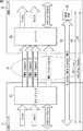
たとえば、図1に示すように、デジタルテレビジョン受像機11と、AVアンプリファイア12とをHDMI(R)に準拠したHDMI(R)ケーブル13で接続することで、画素データおよび音声データの高速な伝送が可能となる。 For example, as shown in FIG. 1, by connecting a
図1では、ユーザ宅の図中、左側に設けられたリビングにデジタルテレビジョン受像機11、AVアンプリファイア12、および再生装置14が設置されており、デジタルテレビジョン受像機11およびAVアンプリファイア12、並びにAVアンプリファイア12および再生装置14がHDMI(R)ケーブル13およびHDMI(R)ケーブル15により接続されている。 In FIG. 1, a
また、リビングには、ハブ16が設置されており、デジタルテレビジョン受像機11および再生装置14は、LAN(Local Area Network)ケーブル17およびLANケーブル18によりハブ16に接続されている。さらに、図中、リビングの右側に設けられた寝室には、デジタルテレビジョン受像機19が設置されており、デジタルテレビジョン受像機19は、LANケーブル20を介してハブ16に接続されている。 A
たとえば、再生装置14に記録されているコンテンツが再生されて、デジタルテレビジョン受像機11に画像が表示される場合、再生装置14は、コンテンツを再生させるための画素データおよび音声データをデコードし、その結果得られた非圧縮の画素データおよび音声データをHDMI(R)ケーブル15、AVアンプリファイア12、およびHDMI(R)ケーブル13を介してデジタルテレビジョン受像機11に供給する。そして、デジタルテレビジョン受像機11は、再生装置14から供給された画素データおよび音声データに基づいて、画像を表示させたり、音声を出力したりする。 For example, when content recorded in the
また、再生装置14に記録されているコンテンツが再生されて、デジタルテレビジョン受像機11およびデジタルテレビジョン受像機19に同時に画像が表示される場合、再生装置14は、圧縮された、コンテンツを再生させるための画素データおよび音声データをLANケーブル18、ハブ16、およびLANケーブル17を介してデジタルテレビジョン受像機11に供給するとともに、LANケーブル18、ハブ16、およびLANケーブル20を介してデジタルテレビジョン受像機19に供給する。 When the content recorded in the
そして、デジタルテレビジョン受像機11およびデジタルテレビジョン受像機19は、再生装置14から供給された画素データおよび音声データをデコードし、その結果得られた非圧縮の画素データおよび音声データに基づいて画像を表示させたり、音声を出力したりする。 Then, the
さらに、デジタルテレビジョン受像機11が、テレビジョン放送されている番組を再生するための画素データおよび音声データを受信した場合、受信された音声データがたとえば5.1チャンネルサラウンドの音声データなどであり、デジタルテレビジョン受像機11が受信した音声データをデコードすることができないときには、デジタルテレビジョン受像機11は、音声データを光信号に変換してAVアンプリファイア12に送信する。 Further, when the
AVアンプリファイア12は、デジタルテレビジョン受像機11から送信されてきた光信号を受信して光電変換し、これにより得られた音声データをデコードする。そして、AVアンプリファイア12は、デコードされた非圧縮の音声データを必要に応じて増幅し、AVアンプリファイア12に接続されたサラウンドスピーカにて音声を再生する。これにより、デジタルテレビジョン受像機11は、受信した画素データをデコードし、デコードされた画素データで画像を表示させ、AVアンプリファイア12に供給した音声データに基づいて、AVアンプリファイア12で音声を出力することで5.1チャンネルサラウンド番組を再生する。 The
ところで、HDMI(R)については、画素データと音声データを、HDMI(R)ソースからHDMI(R)シンクに伝送するときに、データの伝送をオン、オフすることにより、不要なデータをミュートする装置が提案されている(たとえば、特許文献1を参照)。 By the way, for HDMI (R), when transmitting pixel data and audio data from the HDMI (R) source to the HDMI (R) sink, the unnecessary data is muted by turning data transmission on and off. An apparatus has been proposed (see, for example, Patent Document 1).
さらに、HDMI(R)については、HDMI(R)ソースが、画素データと音声データを出力する端子を、切換スイッチによって切り換えることにより、HDMI(R)ソースとHDMI(R)シンクとを接続するケーブルを差し替えることなく、複数のHDMI(R)シンクのうちの、希望するHDMI(R)シンクに、画素データと音声データを出力することができる装置が提案されている(たとえば、特許文献2を参照)。 Furthermore, for HDMI (R), the HDMI (R) source connects the HDMI (R) source and the HDMI (R) sink by switching the terminal that outputs pixel data and audio data with the changeover switch. There has been proposed a device that can output pixel data and audio data to a desired HDMI (R) sink among a plurality of HDMI (R) sinks without replacing the (see, for example, Patent Document 2). ).
上述したように、HDMI(R)では、画素データと音声データを、高速でHDMI(R)ソースからHDMI(R)シンクに、一方向に伝送することができ、かつ、HDMI(R)ソースとHDMI(R)シンクとの間で双方向の通信を行うことができる。 As described above, in HDMI (R), pixel data and audio data can be transmitted in one direction from the HDMI (R) source to the HDMI (R) sink at high speed, and the HDMI (R) source Bidirectional communication can be performed with the HDMI (R) sink.
しかしながら、現行のHDMI(R)において行うことができる双方向の通信の伝送レートは、数百bpsであり、したがって、HDMI(R)ソースとHDMI(R)シンクとの間で、双方向のIP(Internet Protocol)通信などの、双方向の通信を高速に行うことはできなかった。 However, the transmission rate of bidirectional communication that can be performed in the current HDMI (R) is several hundred bps, and therefore, bidirectional IP between the HDMI (R) source and the HDMI (R) sink. Two-way communication such as (Internet Protocol) communication could not be performed at high speed.
このため、特許文献1や特許文献2に記載の装置を含め、HDMI(R)において双方向のIP通信を行う場合には、IP通信で伝送するデータのデータ量が制限される。また、データ量の多いデータをIP通信で伝送すると、大きな遅延時間が生じる。したがって、たとえば、圧縮された画像などのデータ量の多いデータを双方向に伝送することが必要なアプリケーションや、高速な応答を要求するアプリケーションにおいて、HDMI(R)を用いることが困難であった。 For this reason, when bidirectional IP communication is performed in HDMI® including the devices described in
そこで、たとえば、HDMI(R)ソースとHDMI(R)シンクのHDMI(R)用のコネクタに、双方向の高速IP通信用の専用ピンを設け、その専用ピンを用いて双方向のIP通信を高速に行う方法が考えられる。 Therefore, for example, a dedicated pin for bidirectional high-speed IP communication is provided on the HDMI (R) connector of the HDMI (R) source and HDMI (R) sink, and bidirectional IP communication is performed using the dedicated pin. A high-speed method can be considered.
しかしながら、現行のHDMI(R)のコネクタに専用ピンを設けたのでは、現行のHDMI(R)との互換性が損なわれることになる。 However, if a dedicated pin is provided in the current HDMI (R) connector, compatibility with the current HDMI (R) is impaired.
本発明は、このような状況に鑑みてなされたものであり、非圧縮の画像の画素データを一方向に高速伝送することができる、たとえば、HDMI(R)などの通信インタフェースにおいて、互換性を保ちつつ、高速の双方向通信を行うことができるようにするものである。 The present invention has been made in view of such a situation, and can transmit pixel data of an uncompressed image in one direction at a high speed, for example, in a communication interface such as HDMI (R). Thus, high-speed bidirectional communication can be performed while maintaining.
本発明の第1の観点の通信システムは、1の垂直同期信号から次の垂直同期信号までの区間から、水平帰線区間及び垂直帰線区間を除いた区間である有効画像区間において、非圧縮の1画面分の画像の画素データを、第1の差動信号により、受信装置に一方向に送信する送信装置と、前記送信装置から送信されてくる前記第1の差動信号を受信する受信装置とからなる通信システムであって、前記送信装置は、送信するデータであって、前記画素データとは異なるデータを第1の部分信号および第2の部分信号からなる第2の差動信号に変換し、前記第1の部分信号を第1の信号線を介して前記受信装置に送信するとともに、前記第2の部分信号を出力する第1の変換手段と、制御に関する信号である送信信号、または前記第1の変換手段から出力された前記第2の部分信号のうちのいずれかを選択し、選択した信号を第2の信号線を介して前記受信装置に送信する第1の選択手段と、前記送信信号を前記受信装置に送信する場合、前記第1の選択手段により前記送信信号が選択され、前記第2の差動信号を前記受信装置に送信する場合、前記第1の選択手段により前記第2の部分信号が選択されるように制御する第1の制御手段と、前記受信装置から送信されてきた第3の差動信号を受信し、元のデータに復号する第1の復号手段とを備え、前記受信装置は、送信するデータであって、前記画素データとは異なるデータを前記第3の差動信号に変換して前記送信装置に送信する第2の変換手段と、前記送信装置から送信されてきた前記第2の差動信号を受信し、元のデータに復号する第2の復号手段と、前記送信信号または前記第2の部分信号のうちのいずれかを選択する第2の選択手段と、前記送信信号を受信する場合、前記第2の選択手段により前記送信信号が選択されて受信され、前記第2の差動信号を受信する場合、前記第2の選択手段により前記第2の部分信号が選択されて、前記第2の部分信号が前記第2の復号手段により受信されるように制御する第2の制御手段とを備える。 The communication system according to the first aspect of the present invention performs non-compression in an effective image section that is a section obtained by removing a horizontal blanking section and a vertical blanking section from a section from one vertical synchronization signal to the next vertical synchronization signal. A transmission device that transmits pixel data of an image for one screen to a reception device in one direction by a first differential signal, and reception that receives the first differential signal transmitted from the transmission device A communication system comprising a device, wherein the transmission device transmits data, which is different from the pixel data, to a second differential signal comprising a first partial signal and a second partial signal. A first conversion means for converting and transmitting the first partial signal to the receiving device via a first signal line, and outputting the second partial signal; and a transmission signal which is a signal related to control, Or the first conversion means First selecting means for selecting one of the output second partial signals and transmitting the selected signal to the receiving device via a second signal line; and the transmission signal for the receiving device When transmitting to the receiver, the transmission signal is selected by the first selection unit, and when transmitting the second differential signal to the receiving device, the second partial signal is selected by the first selection unit. A first control means for controlling the received data, and a first decoding means for receiving the third differential signal transmitted from the receiving apparatus and decoding the original differential data, the receiving apparatus comprising: Data to be transmitted, which is different from the pixel data, is converted into the third differential signal and transmitted to the transmission device; and the second transmission means transmitted from the transmission device. 2 differential signals are received and decoded into the original data Second decoding means, second selection means for selecting either the transmission signal or the second partial signal, and, when receiving the transmission signal, the transmission by the second selection means When a signal is selected and received and the second differential signal is received, the second selection signal is selected by the second selection means, and the second partial signal is decoded by the second decoding signal. Second control means for controlling to be received by the means.
本発明の第1の観点の通信方法は、1の垂直同期信号から次の垂直同期信号までの区間から、水平帰線区間及び垂直帰線区間を除いた区間である有効画像区間において、非圧縮の1画面分の画像の画素データを、第1の差動信号により、受信装置に一方向に送信する送信装置と、前記送信装置から送信されてくる前記第1の差動信号を受信する受信装置とからなる通信システムの通信方法であって、前記送信装置は、送信するデータであって、前記画素データとは異なるデータを第1の部分信号および第2の部分信号からなる第2の差動信号に変換し、前記第1の部分信号を第1の信号線を介して前記受信装置に送信するとともに、前記第2の部分信号を出力する第1の変換手段と、制御に関する信号である送信信号、または前記第1の変換手段から出力された前記第2の部分信号のうちのいずれかを選択し、選択した信号を第2の信号線を介して前記受信装置に送信する第1の選択手段と、前記受信装置から送信されてきた第3の差動信号を受信し、元のデータに復号する第1の復号手段とを備え、前記受信装置は、送信するデータであって、前記画素データとは異なるデータを前記第3の差動信号に変換して前記送信装置に送信する第2の変換手段と、前記送信装置から送信されてきた前記第2の差動信号を受信し、元のデータに復号する第2の復号手段と、前記送信信号または前記第2の部分信号のうちのいずれかを選択する第2の選択手段とを備え、前記送信信号が前記受信装置に送信される場合、前記第1の選択手段により前記送信信号が選択されるように制御し、前記第2の差動信号が前記受信装置に送信される場合、前記第1の選択手段により前記第2の部分信号が選択されるように制御し、前記送信信号が前記受信装置により受信される場合、前記第2の選択手段により前記送信信号が選択されて受信されるように制御し、前記第2の差動信号が前記受信装置により受信される場合、前記第2の選択手段により前記第2の部分信号が選択されて、前記第2の部分信号が前記第2の復号手段により受信されるように制御するステップを含む。 In the communication method according to the first aspect of the present invention, the non-compression is performed in an effective image section that is a section obtained by removing a horizontal blanking section and a vertical blanking section from a section from one vertical synchronizing signal to the next vertical synchronizing signal. A transmission device that transmits pixel data of an image for one screen to a reception device in one direction by a first differential signal, and reception that receives the first differential signal transmitted from the transmission device A communication method of a communication system comprising a device, wherein the transmission device transmits data that is different from the pixel data by a second difference comprising a first partial signal and a second partial signal. A first conversion means that converts the first partial signal to the receiving device via a first signal line and outputs the second partial signal, and a signal relating to control. Transmitted signal, or said first conversion Selecting one of the second partial signals output from the stage, and transmitting the selected signal to the receiving apparatus via a second signal line; and transmitting from the receiving apparatus A first decoding means for receiving the third differential signal and decoding the original differential data into the original data, wherein the receiving device transmits data that is different from the pixel data. A second conversion means for converting to a differential signal of 3 and transmitting to the transmitter; and a second converter for receiving the second differential signal transmitted from the transmitter and decoding the original data into a second data A decoding means; and a second selection means for selecting either the transmission signal or the second partial signal, and when the transmission signal is transmitted to the receiving device, the first selection means To control the transmission signal to be selected, and When two differential signals are transmitted to the receiving device, the first selection means controls the second partial signal to be selected, and when the transmission signal is received by the receiving device, When the second selection means controls the transmission signal to be selected and received, and the second differential signal is received by the reception device, the second selection means causes the second selection signal to be received. A step of selecting a partial signal and controlling the second partial signal to be received by the second decoding means.
本発明の第1の観点においては、前記送信装置において、送信するデータであって、画素データとは異なるデータが第1の部分信号および第2の部分信号からなる第2の差動信号に変換され、前記第1の部分信号が第1の信号線を介して前記受信装置に送信されるとともに、前記第2の部分信号が出力され、制御に関する信号である送信信号、または出力された前記第2の部分信号のうちのいずれかが選択され、選択された信号が第2の信号線を介して前記受信装置に送信される。ここで、前記送信信号を前記受信装置に送信する場合、前記送信信号が選択され、前記第2の差動信号を前記受信装置に送信する場合、前記第2の部分信号が選択されるように制御される。また、前記受信装置から送信されてきた第3の差動信号が受信され、元のデータに復号される。 In the first aspect of the present invention, in the transmission device, data to be transmitted, which is different from pixel data, is converted into a second differential signal composed of a first partial signal and a second partial signal. The first partial signal is transmitted to the receiving device via the first signal line, and the second partial signal is output, and the transmission signal that is a signal related to control or the output first signal One of the two partial signals is selected, and the selected signal is transmitted to the receiving device via the second signal line. Here, when transmitting the transmission signal to the receiving device, the transmission signal is selected, and when transmitting the second differential signal to the receiving device, the second partial signal is selected. Be controlled. Further, the third differential signal transmitted from the receiving device is received and decoded into the original data.
一方、前記受信装置において、送信するデータであって、前記画素データとは異なるデータが前記第3の差動信号に変換されて前記送信装置に送信され、前記送信装置から送信されてきた前記第2の差動信号が受信され、元のデータに復号され、前記送信信号または前記第2の部分信号のうちのいずれかが選択される。ここで、前記送信信号を受信する場合、前記送信信号が選択されて受信され、前記第2の差動信号を受信する場合、前記第2の部分信号が選択されて、受信されるように制御される。 On the other hand, in the receiving device, data to be transmitted, which is different from the pixel data, is converted into the third differential signal, transmitted to the transmitting device, and transmitted from the transmitting device. Two differential signals are received and decoded into the original data, and either the transmission signal or the second partial signal is selected. Here, when the transmission signal is received, the transmission signal is selected and received, and when the second differential signal is received, the second partial signal is selected and received. Is done.
本発明の第2の観点の送信装置は、1の垂直同期信号から次の垂直同期信号までの区間から、水平帰線区間及び垂直帰線区間を除いた区間である有効画像区間において、非圧縮の1画面分の画像の画素データを、第1の差動信号により、受信装置に一方向に送信する送信装置であって、送信するデータであって、前記画素データとは異なるデータを第1の部分信号および第2の部分信号からなる第2の差動信号に変換し、前記第1の部分信号を第1の信号線を介して前記受信装置に送信するとともに、前記第2の部分信号を出力する変換手段と、制御に関する信号である第1の送信信号、または前記変換手段から出力された前記第2の部分信号のうちのいずれかを選択し、選択した信号を第2の信号線を介して前記受信装置に送信する第1の選択手段と、前記第1の送信信号を前記受信装置に送信する場合、前記第1の選択手段により前記第1の送信信号が選択され、前記第2の差動信号を前記受信装置に送信する場合、前記第1の選択手段により前記第2の部分信号が選択されるように制御する第1の制御手段と、前記受信装置から送信されてきた第3の部分信号と第4の部分信号とからなる第3の差動信号を受信し、元のデータに復号する復号手段とを備える。 The transmitting apparatus according to the second aspect of the present invention performs non-compression in an effective image section that is a section obtained by removing a horizontal blanking section and a vertical blanking section from a section from one vertical synchronization signal to the next vertical synchronization signal. Is a transmission device that transmits pixel data of an image for one screen to a reception device in one direction by a first differential signal, and transmits data that is different from the pixel data. Are converted into a second differential signal composed of a partial signal and a second partial signal, and the first partial signal is transmitted to the receiving device via a first signal line, and the second partial signal is transmitted. And a first transmission signal that is a signal related to control, or the second partial signal output from the conversion means, and the selected signal is selected as a second signal line. First to transmit to the receiving device via And when the first transmission signal is transmitted to the reception device, the first selection signal is selected by the first selection device, and the second differential signal is transmitted to the reception device. A first control unit that controls the second selection signal to be selected by the first selection unit; a third partial signal and a fourth partial signal transmitted from the reception device; And a decoding means for receiving the third differential signal and decoding the original data.
前記復号手段には、前記第2の信号線を介して送信されてきた前記第3の部分信号と、前記第1の信号線を介して送信されてきた前記第4の部分信号とからなる前記第3の差動信号を受信させ、前記第1の選択手段には、前記第2の部分信号若しくは前記第3の部分信号、または前記第1の送信信号を選択させ、前記第1の制御手段には、前記第3の差動信号を受信する場合、前記第1の選択手段により前記第3の部分信号が選択されて、前記第3の部分信号が前記復号手段により受信されるように制御させることができる。 The decoding means includes the third partial signal transmitted via the second signal line and the fourth partial signal transmitted via the first signal line. Receiving a third differential signal, causing the first selection means to select the second partial signal, the third partial signal, or the first transmission signal; and When receiving the third differential signal, control is performed so that the third partial signal is selected by the first selection means and the third partial signal is received by the decoding means. Can be made.
前記第1の選択手段には、前記第2の部分信号若しくは前記第3の部分信号、または前記第1の送信信号、若しくは前記第2の信号線を介して前記受信装置から送信されてきた、制御に関する信号である受信信号を選択させ、前記受信信号が選択された場合、選択された前記受信信号を受信させて出力させるようにすることができる。 The first selection means has been transmitted from the receiving device via the second partial signal or the third partial signal, or the first transmission signal, or the second signal line, When a received signal that is a signal related to control is selected and the received signal is selected, the selected received signal can be received and output.
前記復号手段には、第3の信号線を介して送信されてきた前記第3の部分信号と、第4の信号線を介して送信されてきた前記第4の部分信号とからなる前記第3の差動信号を受信させ、前記第3の部分信号、または前記受信装置に送信する、制御に関する信号である第2の送信信号のうちのいずれかを選択する第2の選択手段と、前記第4の部分信号、または前記受信装置に送信する第3の送信信号のうちのいずれかを選択する第3の選択手段と、前記第2の送信信号および前記第3の送信信号を前記受信装置に送信する場合、前記第2の選択手段により前記第2の送信信号が選択されて、前記第2の送信信号が前記第3の信号線を介して前記受信装置に送信されるとともに、前記第3の選択手段により前記第3の送信信号が選択されて、前記第3の送信信号が前記第4の信号線を介して前記受信装置に送信されるように制御し、前記第3の差動信号を受信する場合、前記第2の選択手段により前記第3の部分信号が選択されて前記復号手段に受信され、前記第3の選択手段により前記第4の部分信号が選択されて前記復号手段に受信されるように制御する第2の制御手段とをさらに設けることができる。 The decoding means includes the third partial signal transmitted via a third signal line and the third partial signal transmitted via a fourth signal line. And a second selection means for selecting either the third partial signal or a second transmission signal that is a signal related to control and is transmitted to the reception device; 4 partial signals or a third transmission signal for selecting a third transmission signal to be transmitted to the receiving device, the second transmission signal and the third transmission signal to the receiving device. In the case of transmission, the second selection signal is selected by the second selection means, and the second transmission signal is transmitted to the reception device via the third signal line, and the third transmission signal is transmitted. When the third transmission signal is selected by the selection means, When the third transmission signal is controlled to be transmitted to the reception device via the fourth signal line and the third differential signal is received, the second selection means causes the third transmission signal to be transmitted to the reception device. There is further provided second control means for controlling so that a partial signal is selected and received by the decoding means, and the fourth partial signal is selected and received by the decoding means by the third selection means. be able to.
前記第1の選択手段には、前記第2の部分信号、または前記第1の送信信号、若しくは前記第2の信号線を介して前記受信装置から送信されてきた、制御に関する信号である第1の受信信号を選択させ、前記第1の受信信号が選択された場合、選択させた前記第1の受信信号を受信させて出力させ、前記第2の選択手段には、前記第3の部分信号、または前記第2の送信信号、若しくは前記第3の信号線を介して前記受信装置から送信されてきた、制御に関する信号である第2の受信信号を選択させ、前記第2の受信信号が選択された場合、選択させた前記第2の受信信号を受信させて出力させることができる。 In the first selection means, the second partial signal, the first transmission signal, or a signal related to control transmitted from the reception device via the second signal line is first. When the first received signal is selected, the selected first received signal is received and output, and the second selecting means has the third partial signal received. Or the second transmission signal or the second reception signal, which is a signal related to control, transmitted from the reception device via the third signal line, is selected, and the second reception signal is selected. If so, the selected second received signal can be received and output.
前記第1の送信信号および前記第1の受信信号は、前記送信装置または前記受信装置の制御用のデータであるCEC(Consumer Electronics Control)信号とされ、前記第2の受信信号は、制御に用いられる、前記受信装置の性能に関する情報であるE-EDID(Enhanced Extended Display Identification Data)とされ、前記第2の差動信号に変換されるデータ、および前記第3の差動信号が復号されて得られたデータは、IP(Internet Protocol)に準拠したデータとされ、前記第1の制御手段には、前記第2の受信信号が受信された後、前記第1の選択手段により前記第2の部分信号が選択されるように制御させ、前記第2の制御手段には、前記第2の受信信号が受信された後、前記第2の選択手段および前記第3の選択手段により、前記第3の部分信号および前記第4の部分信号が選択されるように制御させることができる。 The first transmission signal and the first reception signal are CEC (Consumer Electronics Control) signals which are data for controlling the transmission device or the reception device, and the second reception signal is used for control. E-EDID (Enhanced Extended Display Identification Data), which is information related to the performance of the receiving device, obtained by decoding the data converted to the second differential signal and the third differential signal The received data is data compliant with IP (Internet Protocol), and after the second received signal is received, the first control unit receives the second part by the first selection unit. The second control means receives the second received signal, and then receives the second selection means and the third selection means by the second selection means. Partial signal and said fourth part No. it can be controlled to be selected.
本発明の第2の観点の通信方法またはプログラムは、1の垂直同期信号から次の垂直同期信号までの区間から、水平帰線区間及び垂直帰線区間を除いた区間である有効画像区間において、非圧縮の1画面分の画像の画素データを、第1の差動信号により、受信装置に一方向に送信する送信装置の通信方法または送信装置を制御するコンピュータに実行させるプログラムであり、前記送信装置は、送信するデータであって、前記画素データとは異なるデータを第1の部分信号および第2の部分信号からなる第2の差動信号に変換し、前記第1の部分信号を第1の信号線を介して前記受信装置に送信するとともに、前記第2の部分信号を出力する変換手段と、制御に関する信号である送信信号、または前記変換手段から出力された前記第2の部分信号のうちのいずれかを選択し、選択した信号を第2の信号線を介して前記受信装置に送信する選択手段と、前記受信装置から送信されてきた第3の差動信号を受信し、元のデータに復号する復号手段とを備え、前記送信信号を前記受信装置に送信する場合、前記選択手段により前記送信信号が選択されるように制御し、前記第2の差動信号を前記受信装置に送信する場合、前記選択手段により前記第2の部分信号が選択されるように制御するステップを含む。 The communication method or program according to the second aspect of the present invention is an effective image section that is a section obtained by removing a horizontal blanking section and a vertical blanking section from a section from one vertical synchronization signal to the next vertical synchronization signal. A transmission method for transmitting pixel data of an uncompressed image for one screen to a receiving device in one direction by a first differential signal or a program for causing a computer controlling the transmitting device to execute the transmission The apparatus converts data to be transmitted, which is different from the pixel data, into a second differential signal including a first partial signal and a second partial signal, and the first partial signal is converted into the first partial signal. And a second signal output from the conversion means, a conversion means for transmitting the signal to the receiving device and outputting the second partial signal, and a transmission signal relating to control. A selection means for transmitting the selected signal to the receiving device via a second signal line, and receiving a third differential signal transmitted from the receiving device, Decoding means for decoding the original data, and when the transmission signal is transmitted to the receiving device, the selection means controls the transmission signal to be selected, and the second differential signal is received. In the case of transmitting to the apparatus, the method includes a step of controlling the second partial signal to be selected by the selection means.
本発明の第2の観点においては、送信するデータであって、画素データとは異なるデータが第1の部分信号および第2の部分信号からなる第2の差動信号に変換され、前記第1の部分信号が第1の信号線を介して前記受信装置に送信されるとともに、前記第2の部分信号が出力され、制御に関する信号である第1の送信信号、または出力された前記第2の部分信号のうちのいずれかが選択され、選択された信号が第2の信号線を介して前記受信装置に送信される。ここで、前記第1の送信信号を前記受信装置に送信する場合、前記第1の送信信号が選択され、前記第2の差動信号を前記受信装置に送信する場合、前記第2の部分信号が選択されるように制御される。また、前記受信装置から送信されてきた第3の部分信号と第4の部分信号とからなる第3の差動信号が受信され、元のデータに復号される。 In a second aspect of the present invention, data to be transmitted, which is different from pixel data, is converted into a second differential signal composed of a first partial signal and a second partial signal, and the first Are transmitted to the receiving device via the first signal line, the second partial signal is output, and the first transmission signal that is a signal related to control, or the output second signal One of the partial signals is selected, and the selected signal is transmitted to the receiving device via the second signal line. Here, when transmitting the first transmission signal to the receiving apparatus, the first transmission signal is selected, and when transmitting the second differential signal to the receiving apparatus, the second partial signal Is controlled to be selected. Further, a third differential signal composed of the third partial signal and the fourth partial signal transmitted from the receiving apparatus is received and decoded into the original data.
本発明の第3の観点の受信装置は、1の垂直同期信号から次の垂直同期信号までの区間から、水平帰線区間及び垂直帰線区間を除いた区間である有効画像区間において、送信装置から一方向に送信されてくる、非圧縮の1画面分の画像の画素データを、第1の差動信号により受信する受信装置であって、第1の信号線を介して前記送信装置から送信されてきた第1の部分信号と、第2の信号線を介して前記送信装置から送信されてきた第2の部分信号とからなる第2の差動信号を受信し、元のデータに復号する復号手段と、前記第1の部分信号、または前記第1の信号線を介して前記送信装置から送信されてきた、制御に関する信号である第1の受信信号のうちのいずれかを選択する第1の選択手段と、前記第1の受信信号を受信する場合、前記第1の選択手段により前記第1の受信信号が選択されて受信され、前記第2の差動信号を受信する場合、前記第1の選択手段により前記第1の部分信号が選択されて前記復号手段により受信されるように制御する第1の制御手段と、送信するデータであって、前記画素データとは異なるデータを第3の部分信号および第4の部分信号からなる第3の差動信号に変換して前記送信装置に送信する変換手段とを備える。 The receiving apparatus according to the third aspect of the present invention provides a transmitting apparatus in an effective image section that is a section obtained by removing a horizontal blanking section and a vertical blanking section from a section from one vertical synchronizing signal to the next vertical synchronizing signal. Is a receiving device that receives pixel data of an uncompressed image for one screen that is transmitted in one direction from a first differential signal, and is transmitted from the transmitting device via a first signal line. A second differential signal composed of the first partial signal thus transmitted and the second partial signal transmitted from the transmission device via the second signal line is received and decoded into the original data. A first means for selecting one of a decoding means and a first received signal which is a signal related to control and transmitted from the transmitting device via the first partial signal or the first signal line; And when receiving the first received signal, When the first selection signal is selected and received by the first selection means and the second differential signal is received, the first partial signal is selected by the first selection means and the second selection signal is received. A first control means for controlling the reception so as to be received by the decoding means; and a third differential signal composed of a third partial signal and a fourth partial signal, the data being transmitted and different from the pixel data Conversion means for converting the signal into a signal and transmitting the signal to the transmission device.
前記変換手段には、前記第3の部分信号を出力させるとともに、前記第4の部分信号を前記第2の信号線を介して前記送信装置に送信させ、前記第1の選択手段には、前記第1の受信信号、または前記第1の部分信号、若しくは前記変換手段から出力された前記第3の部分信号を選択させ、前記第1の制御手段には、前記第3の差動信号を送信する場合、前記第1の選択手段により前記第3の部分信号が選択され、前記第1の信号線を介して前記送信装置に送信されるように制御させることができる。 The converting means outputs the third partial signal and transmits the fourth partial signal to the transmitting device via the second signal line, and the first selecting means The first reception signal, the first partial signal, or the third partial signal output from the conversion means is selected, and the first control means transmits the third differential signal. In this case, the third selection signal can be selected by the first selection unit and can be controlled to be transmitted to the transmission device via the first signal line.
前記第1の選択手段には、前記第1の部分信号若しくは前記第3の部分信号、または前記第1の受信信号、若しくは制御に関する信号である送信信号を選択させ、前記送信信号が選択された場合、選択させた前記送信信号を前記第1の信号線を介して前記送信装置に送信させることができる。 The first selection means causes the first partial signal or the third partial signal, or the first reception signal, or a transmission signal that is a control-related signal to be selected, and the transmission signal is selected. In this case, the selected transmission signal can be transmitted to the transmission device via the first signal line.
前記変換手段には、前記第3の部分信号および前記第4の部分信号を出力させ、前記変換手段から出力された前記第3の部分信号、または第3の信号線を介して前記送信装置から送信されてきた、制御に関する信号である第2の受信信号のうちのいずれかを選択する第2の選択手段と、前記変換手段から出力された前記第4の部分信号、または第4の信号線を介して前記送信装置から送信されてきた第3の受信信号のうちのいずれかを選択する第3の選択手段と、前記第2の受信信号および前記第3の受信信号を受信する場合、前記第2の選択手段により前記第2の受信信号が選択されて受信されるとともに、前記第3の選択手段により前記第3の受信信号が選択されて受信されるように制御し、前記第3の差動信号を送信する場合、前記第2の選択手段により前記第3の部分信号が選択され、前記第3の信号線を介して前記送信装置に送信されるとともに、前記第3の選択手段により前記第4の部分信号が選択され、前記第4の信号線を介して前記送信装置に送信されるように制御する第2の制御手段とをさらに設けることができる。 The conversion means outputs the third partial signal and the fourth partial signal, and the third partial signal output from the conversion means or the transmission device via a third signal line Second selection means for selecting one of the received second received signals that are signals relating to control, and the fourth partial signal or fourth signal line output from the conversion means. When receiving the second reception signal and the third reception signal, the third selection means for selecting any one of the third reception signals transmitted from the transmission device via, The second selection signal is selected and received by the second selection means, and the third selection signal is controlled to be selected and received by the third selection means. When transmitting a differential signal, The third partial signal is selected by the selection means and transmitted to the transmission device via the third signal line, and the fourth partial signal is selected by the third selection means, Second control means for controlling to be transmitted to the transmission device via a fourth signal line may be further provided.
前記第1の選択手段には、前記第1の部分信号、または前記第1の受信信号、若しくは前記送信装置に送信される、制御に関する信号である第1の送信信号を選択させ、前記第1の送信信号が選択された場合、選択した前記第1の送信信号を前記第1の信号線を介して前記送信装置に送信させ、前記第2の選択手段には、前記第3の部分信号、または前記第2の受信信号、若しくは前記送信装置に送信される、制御に関する信号である第2の送信信号を選択させ、前記第2の送信信号が選択された場合、選択させた前記第2の送信信号を前記第3の信号線を介して前記送信装置に送信させることができる。 The first selection means selects the first partial signal, the first reception signal, or a first transmission signal that is a signal related to control and is transmitted to the transmission device, and When the transmission signal is selected, the selected first transmission signal is transmitted to the transmission device via the first signal line, and the second selection unit includes the third partial signal, Alternatively, when the second transmission signal that is a control-related signal transmitted to the transmission device is selected, and the second transmission signal is selected, the selected second transmission signal is selected. A transmission signal can be transmitted to the transmission device via the third signal line.
本発明の第3の観点の通信方法またはプログラムは、1の垂直同期信号から次の垂直同期信号までの区間から、水平帰線区間及び垂直帰線区間を除いた区間である有効画像区間において、送信装置から一方向に送信されてくる、非圧縮の1画面分の画像の画素データを、第1の差動信号により受信する受信装置の通信方法、または受信装置を制御するコンピュータに実行させるプログラムであり、前記受信装置は、第1の信号線を介して前記送信装置から送信されてきた第1の部分信号と、第2の信号線を介して前記送信装置から送信されてきた第2の部分信号とからなる第2の差動信号を受信し、元のデータに復号する復号手段と、前記第1の部分信号、または前記第1の信号線を介して前記送信装置から送信されてきた、制御に関する信号である受信信号のうちのいずれかを選択する選択手段と、送信するデータであって、前記画素データとは異なるデータを第3の差動信号に変換して前記送信装置に送信する変換手段とを備え、前記受信信号を受信する場合、前記選択手段により前記受信信号が選択されて受信されるように制御し、前記第2の差動信号を受信する場合、前記選択手段により前記第1の部分信号が選択されて前記復号手段により受信されるように制御するステップを含む。 The communication method or program according to the third aspect of the present invention is an effective image section that is a section obtained by removing a horizontal blanking section and a vertical blanking section from a section from one vertical synchronization signal to the next vertical synchronization signal. A communication method of a receiving apparatus that receives pixel data of an uncompressed image for one screen that is transmitted in one direction from the transmitting apparatus using a first differential signal, or a program that is executed by a computer that controls the receiving apparatus The receiving device includes a first partial signal transmitted from the transmitting device via a first signal line and a second partial signal transmitted from the transmitting device via a second signal line. Received from the transmitter via the first partial signal or the first signal line, the decoding means for receiving the second differential signal composed of the partial signal and decoding it into the original data , Communication regarding control Selecting means for selecting any one of the received signals, and converting means for transmitting data that is different from the pixel data into a third differential signal and transmitting the third differential signal to the transmitting device; When the reception signal is received, the selection unit controls the reception signal to be selected and received. When the second differential signal is received, the selection unit receives the first signal. Controlling to select a partial signal to be received by the decoding means.
本発明の第3の観点においては、第1の信号線を介して前記送信装置から送信されてきた第1の部分信号と、第2の信号線を介して前記送信装置から送信されてきた第2の部分信号とからなる第2の差動信号が受信され、元のデータに復号され、前記第1の部分信号、または前記第1の信号線を介して前記送信装置から送信されてきた、制御に関する信号である第1の受信信号のうちのいずれかが選択される。ここで、前記第1の受信信号を受信する場合、前記第1の受信信号が選択されて受信され、前記第2の差動信号を受信する場合、前記第1の部分信号が選択されて受信されるように制御される。また、送信するデータであって、前記画素データとは異なるデータが第3の部分信号および第4の部分信号からなる第3の差動信号に変換されて前記送信装置に送信される。 In the third aspect of the present invention, the first partial signal transmitted from the transmission device via the first signal line and the first partial signal transmitted from the transmission device via the second signal line are provided. A second differential signal composed of two partial signals is received, decoded into original data, and transmitted from the transmission device via the first partial signal or the first signal line; One of the first received signals that are signals related to control is selected. Here, when receiving the first received signal, the first received signal is selected and received, and when receiving the second differential signal, the first partial signal is selected and received. To be controlled. Further, data to be transmitted, which is different from the pixel data, is converted into a third differential signal composed of a third partial signal and a fourth partial signal and transmitted to the transmission device.
本発明の第4の観点の通信ケーブルは、1の垂直同期信号から次の垂直同期信号までの区間から、水平帰線区間及び垂直帰線区間を除いた区間である有効画像区間において、非圧縮の1画面分の画像の画素データを、第1の差動信号により、受信装置に一方向に送信する送信装置であり、送信するデータであって、前記画素データとは異なるデータを第1の部分信号および第2の部分信号からなる第2の差動信号に変換し、前記第1の部分信号を第1の信号線を介して前記受信装置に送信するとともに、前記第2の部分信号を出力する第1の変換手段と、制御に関する信号である送信信号、または前記第1の変換手段から出力された前記第2の部分信号のうちのいずれかを選択し、選択した信号を第2の信号線を介して前記受信装置に送信する第1の選択手段と、前記送信信号を前記受信装置に送信する場合、前記第1の選択手段により前記送信信号が選択され、前記第2の差動信号を前記受信装置に送信する場合、前記第1の選択手段により前記第2の部分信号が選択されるように制御する第1の制御手段と、前記受信装置から送信されてきた第3の差動信号を受信し、元のデータに復号する第1の復号手段とを備える送信装置と、前記送信装置から送信されてくる前記第1の差動信号を受信する受信装置であり、送信するデータであって、前記画素データとは異なるデータを前記第3の差動信号に変換して前記送信装置に送信する第2の変換手段と、前記送信装置から送信されてきた前記第2の差動信号を受信し、元のデータに復号する第2の復号手段と、前記第2の部分信号、または前記送信信号のうちのいずれかを選択する第2の選択手段と、前記送信信号を受信する場合、前記第2の選択手段により前記送信信号が選択されて受信され、前記第2の差動信号を受信する場合、前記第2の選択手段により前記第2の部分信号が選択されて、前記第2の部分信号が前記第2の復号手段により受信されるように制御する第2の制御手段とを備える受信装置とを接続する通信ケーブルであり、前記第1の信号線および前記第2の信号線を備え、前記第1の信号線と、前記第2の信号線とが差動ツイストペア結線されている。 The communication cable according to the fourth aspect of the present invention is a non-compressed in an effective image section that is a section obtained by removing a horizontal blanking section and a vertical blanking section from a section from one vertical synchronizing signal to the next vertical synchronizing signal. Is a transmission device that transmits pixel data of an image of one screen to a reception device in one direction by a first differential signal, and transmits data that is different from the pixel data in the first The first partial signal is converted to a second differential signal composed of a partial signal and a second partial signal, and the first partial signal is transmitted to the receiving device via a first signal line. The first conversion means to output, a transmission signal that is a signal related to control, or the second partial signal output from the first conversion means is selected, and the selected signal is set to the second Transmit to the receiver via a signal line When transmitting the transmission signal to the reception device with the first selection means, the transmission signal is selected by the first selection means, and when transmitting the second differential signal to the reception device, First control means for controlling the second partial signal to be selected by the first selection means, and the third differential signal transmitted from the receiving device is received and decoded into the original data A first decoding unit that receives the first differential signal transmitted from the transmission device, and data to be transmitted, the data being different from the pixel data Is converted into the third differential signal and transmitted to the transmitter, and the second differential signal transmitted from the transmitter is received and decoded into the original data. Second decoding means and said second partial signal Or a second selection unit that selects one of the transmission signals and, when receiving the transmission signal, the transmission signal is selected and received by the second selection unit; When receiving a signal, second control means for controlling the second partial signal to be selected by the second selection means and received by the second decoding means. A communication cable for connecting to a receiving device comprising: the first signal line and the second signal line, wherein the first signal line and the second signal line are differential twisted pair connections Has been.
本発明の第4の観点においては、送信装置と受信装置とを接続する通信ケーブルに、第1の信号線および第2の信号線が設けられ、前記第1の信号線と、前記第2の信号線とが差動ツイストペア結線されている。 In a fourth aspect of the present invention, a communication cable connecting a transmission device and a reception device is provided with a first signal line and a second signal line, and the first signal line and the second signal line are provided. The signal line is connected with a differential twisted pair.
本発明の第5の観点は、1本のケーブルで映像と音声のデータ伝送と接続機器情報の交換および認証、機器制御データの通信、並びにLAN通信を行うインタフェースを含む通信システムであって、接続対応機器を接続可能な1対の差動伝送路を有し、LAN通信が前記1対の差動伝送路を介した双方向通信で行われ、当該1対の差動伝送路のうちの少なくとも一方のDCバイアス電位によってインタフェースの接続状態を通知する機能を有する。 According to a fifth aspect of the present invention, there is provided a communication system including an interface for performing video and audio data transmission and connection device information exchange and authentication, device control data communication, and LAN communication with a single cable. A pair of differential transmission paths to which a compatible device can be connected, LAN communication is performed by bidirectional communication via the pair of differential transmission paths, and at least one of the pair of differential transmission paths. One DC bias potential has a function of notifying the connection state of the interface.
本発明の第6の観点は、1本のケーブルで映像と音声のデータ伝送と接続機器情報の交換および認証、機器制御データの通信、並びにLAN通信を行うインタフェースを含む通信システムであって、接続対応機器を接続可能な2対の差動伝送路を有し、LAN通信が2対の差動伝送路を介する単方向通信で行われ、前記伝送路のうちの少なくとも一つの伝送路のDCバイアス電位によってインタフェースの接続状態が通知する機能を有し、少なくとも二つの伝送路がLAN通信とは時分割で接続機器情報の交換と認証の通信に使われる。 A sixth aspect of the present invention is a communication system including an interface for performing video and audio data transmission and connection device information exchange and authentication, device control data communication, and LAN communication with a single cable. Two pairs of differential transmission lines that can be connected to a corresponding device, LAN communication is performed by unidirectional communication via two pairs of differential transmission lines, and a DC bias of at least one of the transmission lines The interface has a function of notifying the connection state of the interface according to the potential, and at least two transmission paths are used for the exchange of connected device information and the communication for authentication in a time-sharing manner with the LAN communication.
本発明によれば、双方向通信を行うことができる。特に、たとえば非圧縮の画像の画素データと、その画像に付随する音声データとを、一方向に高速伝送することができる通信インタフェースにおいて、互換性を保ちつつ、高速の双方向通信を行うことが可能となる。
また、本発明によれば、DDCに関して規定された電気的仕様と無関係にLAN通信のための回路を形成することができ、安定で確実なLAN通信が安価に実現できる。According to the present invention, bidirectional communication can be performed. In particular, for example, in a communication interface that can transmit pixel data of an uncompressed image and audio data accompanying the image in one direction at a high speed, high-speed bidirectional communication can be performed while maintaining compatibility. It becomes possible.
Furthermore, according to the present invention, a circuit for LAN communication can be formed regardless of the electrical specifications defined for DDC, and stable and reliable LAN communication can be realized at low cost.
35 HDMI(R)ケーブル, 71 HDMI(R)ソース, 72 HDMI(R)シンク, 81 トランスミッタ, 82 レシーバ, 83 DDC, 84 CECライン, 85 EDIDROM, 121 切り換え制御部, 124 切り換え制御部, 131 変換部, 132 復号部, 133 スイッチ, 134 変換部, 135 スイッチ, 136 復号部, 141 信号線, 171 切り換え制御部, 172 切り換え制御部, 181 スイッチ, 182 スイッチ, 183 復号部, 184 変換部, 185 スイッチ, 186 スイッチ, 191 SDAライン, 192 SCLライン, 400 通信システム, 401 LAN機能拡張HDMI(EH)ソース機器, 411 LAN信号送信回路, 412 終端抵抗, 413,414 AC結合容量, 415 LAN信号受信回路, 416 減算回路, 421 プルアップ抵抗, 422 抵抗, 423 容量, 424 比較器, 431 プルダウン抵抗, 432 抵抗, 433 容量, 434 比較器, 402 EHシンク機器, 441 LAN信号送信回路, 442 終端抵抗, 443,444 AC結合容量, 445 LAN信号受信回路, 446 減算回路, 451 プルダウン抵抗, 452 抵抗, 453 容量, 454 比較器, 461 チョークコイル, 462,463 抵抗, 403 EHケーブル, 501 リザーブライン, 502 HPDライン, 511,512 ソース側端子, 521,522 シンク側端子, 600 通信システム, 601 LAN機能拡張HDMI(EH)ソース機器, 611 LAN信号送信回路, 612,613 終端抵抗, 614〜617 AC結合容量, 618 LAN信号受信回路, 620 インバータ, 621 抵抗, 622 抵抗, 623 容量, 624 比較器, 631 プルダウン抵抗, 632 抵抗, 633 容量, 634 比較器, 640 NORゲート, 641〜644 アナログスイッチ, 645 インバータ, 646,647 アナログスイッチ, 651,652 DDCトランシーバ, 653,654 プルアップ抵抗, 602 EHシンク機器, 661 LAN信号送信回路, 662,663 終端抵抗, 664〜667 AC結合容量, 668 LAN信号受信回路, 671 プルダウン抵抗, 672 抵抗, 673 容量, 674 比較器, 681 チョークコイル, 682,683 抵抗, 691〜694 アナログスイッチ, 695 インバータ, 696,697 アナログスイッチ, 701,702 DDCトランシーバ, 703 プルアップ抵抗, 603 EHケーブル, 801 リザーブライン, 802 HPDライン, 803 SCLライン, 804 SDAライン, 811〜814 ソース側端子, 821〜824 シンク側端子 35 HDMI (R) cable, 71 HDMI (R) source, 72 HDMI (R) sink, 81 transmitter, 82 receiver, 83 DDC, 84 CEC line, 85 EDIDROM, 121 switching control unit, 124 switching control unit, 131 conversion unit , 132 decoding section, 133 switch, 134 conversion section, 135 switch, 136 decoding section, 141 signal line, 171 switching control section, 172 switching control section, 181 switch, 182 switch, 183 decoding section, 184 conversion section, 185 switch, 186 switch, 191 SDA line, 192 SCL line, 400 communication system, 401 LAN function expansion HDMI (EH) source device, 411 LAN signal transmission circuit, 412 termination resistor, 413, 414 AC coupling capacity, 415 L N signal reception circuit, 416 subtraction circuit, 421 pull-up resistor, 422 resistor, 423 capacitor, 424 comparator, 431 pull-down resistor, 432 resistor, 433 capacitor, 434 comparator, 402 EH sink device, 441 LAN signal transmission circuit, 442 Termination resistor, 443,444 AC coupling capacitance, 445 LAN signal receiving circuit, 446 subtraction circuit, 451 pull-down resistor, 452 resistor, 453 capacitance, 454 comparator, 461 choke coil, 462, 463 resistor, 403 EH cable, 501 reserved line , 502 HPD line, 511, 512 source side terminal, 521, 522 sink side terminal, 600 communication system, 601 LAN function extended HDMI (EH) source device, 611 LAN signal Transmitter circuit, 612, 613 termination resistor, 614-617 AC coupling capacitor, 618 LAN signal receiver circuit, 620 inverter, 621 resistor, 622 resistor, 623 capacitor, 624 comparator, 631 pull-down resistor, 632 resistor, 633 capacitor, 634 comparison 640 NOR gate, 641-644 analog switch, 645 inverter, 646,647 analog switch, 651,652 DDC transceiver, 653,654 pull-up resistor, 602 EH sink device, 661 LAN signal transmission circuit, 662,663 termination resistor , 664 to 667 AC coupling capacity, 668 LAN signal receiving circuit, 671 pull-down resistance, 672 resistance, 673 capacity, 674 comparator, 681 choke coil, 682, 683 resistor, 691-694 analog switch, 695 inverter, 696, 697 analog switch, 701, 702 DDC transceiver, 703 pull-up resistor, 603 EH cable, 801 reserved line, 802 HPD line, 803 SCL line, 804 SDA line , 811 to 814 Source side terminal, 821 to 824 Sink side terminal
以下、図面を参照して、本発明を適用した実施の形態について説明する。 Embodiments to which the present invention is applied will be described below with reference to the drawings.
図2は、本発明を適用した一実施の形態の画像伝送システムの構成を示す図である。 FIG. 2 is a diagram showing a configuration of an image transmission system according to an embodiment to which the present invention is applied.
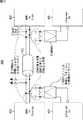
画像伝送システムは、デジタルテレビジョン受像機31、増幅器32、再生装置33、およびデジタルテレビジョン受像機34により構成され、デジタルテレビジョン受像機31および増幅器32、並びに増幅器32および再生装置33は、HDMI(R)に準拠した通信ケーブルであるHDMI(R)ケーブル35およびHDMI(R)ケーブル36により接続されている。また、デジタルテレビジョン受像機31およびデジタルテレビジョン受像機34は、Ethernet(登録商標)などのLAN用のLANケーブル37により接続されている。 The image transmission system includes a
図2の例では、デジタルテレビジョン受像機31、増幅器32、および再生装置33が、ユーザ宅の図中、左側に設けられたリビングに設置されており、デジタルテレビジョン受像機34が、リビングの右側に設けられた寝室に設置されている。 In the example of FIG. 2, a
再生装置33は、たとえばDVDプレーヤ、ハードディスクレコーダなどからなり、コンテンツを再生するための画素データおよび音声データをデコードし、その結果得られた非圧縮の画素データおよび音声データを、HDMI(R)ケーブル36を介して増幅器32に供給する。 The
増幅器32は、たとえばAVアンプリファイアなどからなり、再生装置33から画素データおよび音声データの供給を受け、供給された音声データを必要に応じて増幅する。また、増幅器32は、再生装置33から供給され、必要に応じて増幅された音声データ、および画素データを、HDMI(R)ケーブル35を介してデジタルテレビジョン受像機31に供給する。デジタルテレビジョン受像機31は、増幅器32から供給された画素データおよび音声データに基づいて画像を表示したり、音声を出力したりして、コンテンツを再生する。 The
また、デジタルテレビジョン受像機31および増幅器32は、HDMI(R)ケーブル35を利用して、たとえばIP通信などの双方向の通信を高速に行うことができ、増幅器32および再生装置33もHDMI(R)ケーブル36を利用して、たとえばIP通信などの双方向の通信を高速に行うことができる。 In addition, the
すなわち、たとえば再生装置33は、増幅器32とIP通信を行うことで、IPに準拠したデータとして、圧縮された画素データおよび音声データを、HDMI(R)ケーブル36を介して増幅器32に送信することができ、増幅器32は、再生装置33から送信されてきた、圧縮された画素データおよび音声データを受信することができる。 That is, for example, the
また、増幅器32は、デジタルテレビジョン受像機31とIP通信を行うことで、IPに準拠したデータとして、圧縮された画素データおよび音声データを、HDMI(R)ケーブル35を介してデジタルテレビジョン受像機31に送信することができ、デジタルテレビジョン受像機31は、増幅器32から送信されてきた、圧縮された画素データおよび音声データを受信することができる。 In addition, the
したがって、デジタルテレビジョン受像機31は、受信した画素データおよび音声データを、LANケーブル37を介してデジタルテレビジョン受像機34に送信することができる。また、デジタルテレビジョン受像機31は、受信した画素データおよび音声データをデコードし、これにより得られた非圧縮の画素データおよび音声データに基づいて、画像を表示したり、音声を出力したりしてコンテンツを再生する。 Therefore, the
デジタルテレビジョン受像機34は、LANケーブル37を介してデジタルテレビジョン受像機31から送信されてきた画素データおよび音声データを受信してデコードし、デコードにより得られた非圧縮の画素データおよび音声データに基づいて、画像を表示したり、音声を出力したりしてコンテンツを再生する。これにより、デジタルテレビジョン受像機31およびデジタルテレビジョン受像機34において、同一あるいは異なるコンテンツを同時に再生することができる。 The
さらに、デジタルテレビジョン受像機31が、テレビジョン放送されているコンテンツとしての番組を再生するための画素データおよび音声データを受信した場合、受信された音声データがたとえば5.1チャンネルサラウンドの音声データなどであり、デジタルテレビジョン受像機31が受信した音声データをデコードすることができないときには、デジタルテレビジョン受像機31は、増幅器32とIP通信することで、受信した音声データをHDMI(R)ケーブル35を介して増幅器32に送信する。 Further, when the
増幅器32は、デジタルテレビジョン受像機31から送信されてきた音声データを受信してデコードするとともに、必要に応じてデコードされた音声データを増幅する。そして、増幅器32に接続されたスピーカ(図示せず)により5.1チャンネルサラウンド音声を再生する。 The
デジタルテレビジョン受像機31は、HDMI(R)ケーブル35を介して増幅器32に音声データを送信するとともに、受信した画素データをデコードし、デコードにより得られた画素データに基づいて画像を表示させて番組を再生する。 The
このように、図2の画像伝送システムにおいては、HDMI(R)ケーブル35やHDMI(R)ケーブル36により接続されているデジタルテレビジョン受像機31、増幅器32、再生装置33などの電子機器は、HDMI(R)ケーブルを用いて高速にIP通信することができるため、図1のLANケーブル17に対応するLANケーブルは必要とされない。 As described above, in the image transmission system of FIG. 2, electronic devices such as the
また、デジタルテレビジョン受像機31とデジタルテレビジョン受像機34とをLANケーブル37で接続することで、デジタルテレビジョン受像機31がHDMI(R)ケーブル36、増幅器32、およびHDMI(R)ケーブル35を介して再生装置33から受信したデータを、さらにLANケーブル37を介してデジタルテレビジョン受像機34に送信することができるので、図1のLANケーブル18およびハブ16に対応するLANケーブルや電子機器も必要ない。 Further, the
図1に示したように、従来の画像伝送システムにおいては、送受信するデータや通信方式によって、それぞれ異なる種類のケーブルが必要であり、電子機器同士を接続するケーブルの配線が煩雑であった。これに対して、図2に示した画像伝送システムにおいては、HDMI(R)ケーブルにより接続された電子機器間では、高速にIP通信などの双方向の通信を行うことができるので、電子機器の接続を簡素化することができる。つまり、従来は複雑であった電子機器同士を接続するケーブルの配線を、より簡単にすることができる。 As shown in FIG. 1, in the conventional image transmission system, different types of cables are required depending on the data to be transmitted and received and the communication method, and the wiring of the cables connecting the electronic devices is complicated. On the other hand, in the image transmission system shown in FIG. 2, bi-directional communication such as IP communication can be performed at high speed between electronic devices connected by an HDMI (R) cable. Connection can be simplified. That is, the wiring of the cable for connecting electronic devices, which has been complicated in the past, can be simplified.
次に、図3は、HDMI(R)ケーブルにより互いに接続された電子機器のそれぞれに内蔵されたHDMI(R)ソースおよびHDMI(R)シンク、たとえば図2の増幅器32内に設けられたHDMI(R)ソース、およびデジタルテレビジョン受像機31内に設けられたHDMI(R)シンクの構成例を示している。 Next, FIG. 3 shows an HDMI (R) source and an HDMI (R) sink built in each of the electronic devices connected to each other by an HDMI (R) cable, for example, HDMI (in the
HDMI(R)ソース71とHDMI(R)シンク72とは、1本のHDMI(R)ケーブル35で接続されており、HDMI(R)ソース71およびHDMI(R)シンク72は、現行のHDMI(R)との互換性を保ちながら、HDMI(R)ケーブル35を利用して、高速で双方向のIP通信を行うことができる。 The HDMI (R)
HDMI(R)ソース71は、1の垂直同期信号から次の垂直同期信号までの区間から、水平帰線区間及び垂直帰線区間を除いた区間である有効画像区間(以下、適宜、アクティブビデオ区間ともいう)において、非圧縮の1画面分の画像の画素データに対応する差動信号を、複数のチャンネルで、HDMI(R)シンク72に一方向に送信するとともに、水平帰線区間または垂直帰線区間において、少なくとも画像に付随する音声データや制御データ、その他の補助データ等に対応する差動信号を、複数のチャンネルで、HDMI(R)シンク72に一方向に送信する。 The HDMI (R)
すなわち、HDMI(R)ソース71は、トランスミッタ81を有する。トランスミッタ81は、たとえば、非圧縮の画像の画素データを対応する差動信号に変換し、複数のチャンネルである3つのTMDSチャンネル#0,#1,#2で、HDMI(R)ケーブル35を介して接続されているHDMI(R)シンク72に、一方向にシリアル伝送する。 That is, the HDMI (R)
また、トランスミッタ81は、非圧縮の画像に付随する音声データ、さらには、必要な制御データその他の補助データ等を、対応する差動信号に変換し、3つのTMDSチャンネル#0,#1,#2でHDMI(R)ケーブル35を介して接続されているHDMI(R)シンク72に、一方向にシリアル伝送する。 The
さらに、トランスミッタ81は、3つのTMDSチャンネル#0,#1,#2で送信する画素データに同期したピクセルクロックを、TMDSクロックチャンネルで、HDMI(R)ケーブル35を介して接続されているHDMI(R)シンク72に送信する。ここで、1つのTMDSチャンネル#i(i=0,1,2)では、ピクセルクロックの1クロックの間に、10ビットの画素データが送信される。 Further, the
HDMI(R)シンク72は、アクティブビデオ区間において、複数のチャンネルで、HDMI(R)ソース71から一方向に送信されてくる、画素データに対応する差動信号を受信するとともに、水平帰線区間または垂直帰線区間において、複数のチャンネルで、HDMI(R)ソース71から一方向に送信されてくる、音声データや制御データに対応する差動信号を受信する。 The HDMI (R) sink 72 receives a differential signal corresponding to pixel data transmitted in one direction from the HDMI (R)
すなわち、HDMI(R)シンク72は、レシーバ82を有する。レシーバ82は、TMDSチャンネル#0,#1,#2で、HDMI(R)ケーブル35を介して接続されているHDMI(R)ソース71から一方向に送信されてくる、画素データに対応する差動信号と、音声データや制御データに対応する差動信号を、同じくHDMI(R)ソース71からTMDSクロックチャンネルで送信されてくるピクセルクロックに同期して受信する。 That is, the HDMI (R) sink 72 has a
HDMI(R)ソース71とHDMI(R)シンク72とからなるHDMI(R)システムの伝送チャンネルには、HDMI(R)ソース71からHDMI(R)シンク72に対して、画素データおよび音声データを、ピクセルクロックに同期して、一方向にシリアル伝送するための伝送チャンネルとしての3つのTMDSチャンネル#0乃至#2と、ピクセルクロックを伝送する伝送チャンネルとしてのTMDSクロックチャンネルとの他に、DDC(Display Data Channel)83やCECライン84と呼ばれる伝送チャンネルがある。 The transmission channel of the HDMI (R) system including the HDMI (R)
DDC83は、HDMI(R)ケーブル35に含まれる図示せぬ2本の信号線からなり、HDMI(R)ソース71が、HDMI(R)ケーブル35を介して接続されたHDMI(R)シンク72から、E-EDID(Enhanced Extended Display Identification Data)を読み出すのに使用される。 The
すなわち、HDMI(R)シンク72は、レシーバ82の他に自身の設定や性能に関する情報であるE-EDIDを記憶しているEDIDROM(EDID ROM(Read Only Memory))85を有している。HDMI(R)ソース71は、HDMI(R)ケーブル35を介して接続されているHDMI(R)シンク72から、そのHDMI(R)シンク72のEDIDROM85が記憶しているE-EDIDをDDC83を介して読み出し、そのE-EDIDに基づき、HDMI(R)シンク72の設定や性能、すなわち、たとえばHDMI(R)シンク72(を有する電子機器)が対応している画像のフォーマット(プロファイル)、たとえばRGB(Red,Green,Blue)や、YCbCr4:4:4,YCbCr4:2:2などを認識する。 That is, the HDMI (R) sink 72 has an EDIDROM (EDID ROM (Read Only Memory)) 85 that stores E-EDID, which is information related to its settings and performance, in addition to the
なお、図示していないが、HDMI(R)ソース71もHDMI(R)シンク72と同様に、E-EDIDを記憶し、必要に応じてそのE-EDIDをHDMI(R)シンク72に送信することができる。 Although not shown, the HDMI (R)
CECライン84は、HDMI(R)ケーブル35に含まれる図示せぬ1本の信号線からなり、HDMI(R)ソース71とHDMI(R)シンク72との間で、制御用のデータの双方向通信を行うのに用いられる。 The
また、HDMI(R)ソース71およびHDMI(R)シンク72は、DDC83またはCECライン84を介して、たとえば、IEEE(Institute of Electrical and Electronics Engineers)802.3に準拠したフレームをHDMI(R)シンク72およびHDMI(R)ソース71に送信することにより、双方向のIP通信を行うことができる。 Also, the HDMI (R)
さらに、HDMI(R)ケーブル35には、Hot Plug Detectと呼ばれるピンに接続される信号線86が含まれており、HDMI(R)ソース71およびHDMI(R)シンク72は、この信号線86を利用して、新たな電子機器、つまりHDMI(R)シンク72またはHDMI(R)ソース71の接続を検出することができる。 Further, the HDMI (R)
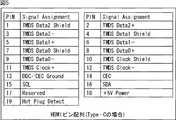
次に、図4および図5は、HDMI(R)ケーブル35と接続される、HDMI(R)ソース71またはHDMI(R)シンク72に設けられた図示せぬコネクタのピン配列(pin assignment)を示している。 Next, FIGS. 4 and 5 show pin assignments (not shown) of connectors (not shown) provided in the HDMI (R)
なお、図4および図5においては、左欄(PINの欄)に、コネクタのピンを特定するピン番号を記載してあり、右欄(Signal Assignmentの欄)に、同一行の左欄に記載されているピン番号で特定されるピンに割り当てられている信号の名称を記載してある。 In FIG. 4 and FIG. 5, the left column (PIN column) indicates the pin number for identifying the connector pin, and the right column (Signal Assignment column) describes the pin number in the left column. The name of the signal assigned to the pin specified by the pin number is indicated.
図4は、HDMI(R)のタイプA(Type-A)と呼ばれるコネクタのピン配列を示している。 FIG. 4 shows a connector pin arrangement called HDMI (R) type A (Type-A).
TMDSチャンネル#iの差動信号TMDS Data#i+とTMDS Data#i-が伝送される差動信号線である2本の信号線は、TMDS Data#i+が割り当てられているピン(ピン番号が1,4,7のピン)と、TMDS Data#i-が割り当てられているピン(ピン番号が3,6,9のピン)に接続される。 Two signal lines, which are differential signal lines through which TMDS Data # i + and TMDS Data # i- of TMDS channel #i are transmitted, are assigned to pins assigned with TMDS Data # i + (the pin number is 1). , 4 and 7) and pins to which TMDS Data # i- is assigned (pins with
また、制御用のデータであるCEC信号が伝送されるCECライン84は、ピン番号が13であるピンに接続され、ピン番号が14のピンは空き(Reserved)ピンとなっている。双方向のIP通信を、この空きピンを利用して行うことができれば、現行のHDMI(R)との互換性を保つことができる。そこで、CECライン84およびピン番号が14のピンに接続される信号線を用いて差動信号を伝送することができるように、ピン番号が14のピンに接続される信号線と、CECライン84とは、差動ツイストペア結線されてシールドされ、ピン番号が17番のピンに接続されるCECライン84およびDDC83のグランド線に接地されている。 A
さらに、E-EDIDなどのSDA(Serial Data)信号が伝送される信号線は、ピン番号が16であるピンに接続され、SDA信号の送受信時の同期に用いられるクロック信号であるSCL(Serial Clock)信号が伝送される信号線は、ピン番号が15であるピンに接続される。図3のDDC83は、SDA信号が伝送される信号線、およびSCL信号が伝送される信号線から構成される。 Further, a signal line for transmitting an SDA (Serial Data) signal such as E-EDID is connected to a pin having a pin number of 16, and SCL (Serial Clock) which is a clock signal used for synchronization at the time of transmission / reception of the SDA signal. ) A signal line through which a signal is transmitted is connected to a pin having a pin number of 15. The
また、SDA信号が伝送される信号線、およびSCL信号が伝送される信号線は、CECライン84およびピン番号が14のピンに接続される信号線と同様に、差動信号を伝送することができるように差動ツイストペア結線されてシールドされ、ピン番号が17番のピンに接続されるグランド線に接地されている。 Further, the signal line for transmitting the SDA signal and the signal line for transmitting the SCL signal can transmit differential signals in the same manner as the signal line connected to the
さらに、新たな電子機器の接続を検出するための信号が伝送される信号線86は、ピン番号が19であるピンに接続される。 Further, a
図5は、HDMI(R)のタイプC(Type-C)またはタイプミニと呼ばれるコネクタのピン配列を示している。 FIG. 5 shows a pin arrangement of a connector called Type C (Type-C) or Type Mini of HDMI (R).
TMDSチャンネル#iの差動信号TMDS Data#i+とTMDS Data#i-が伝送される差動信号線である2本の信号線は、TMDS Data#i+が割り当てられているピン(ピン番号が2,5,8のピン)と、TMDS Data#i-が割り当てられているピン(ピン番号が3,6,9のピン)に接続される。 Two signal lines, which are differential signal lines that transmit TMDS Data # i + and TMDS Data # i- differential signals of TMDS channel #i, are pins to which TMDS Data # i + is assigned (pin number 2) , 5 and 8) and TMDS Data # i- assigned pins (
また、CEC信号が伝送されるCECライン84は、ピン番号が14であるピンに接続され、ピン番号が17のピンは空き(Reserved)ピンとなっている。ピン番号が17のピンに接続される信号線と、CECライン84とは、タイプAにおける場合と同様に差動ツイストペア結線されてシールドされ、ピン番号が13番のピンに接続されるCECライン84およびDDC83のグランド線に接地されている。 The
さらに、SDA信号が伝送される信号線は、ピン番号が16であるピンに接続され、SCL信号が伝送される信号線は、ピン番号が15であるピンに接続される。また、SDA信号が伝送される信号線、およびSCL信号が伝送される信号線は、タイプAにおける場合と同様に、差動信号を伝送することができるように差動ツイストペア結線されてシールドされ、ピン番号が13番のピンに接続されるグランド線に接地されている。さらに、また、新たな電子機器の接続を検出するための信号が伝送される信号線86は、ピン番号が19であるピンに接続される。 Further, a signal line for transmitting the SDA signal is connected to a pin having a pin number of 16, and a signal line for transmitting an SCL signal is connected to a pin having a pin number of 15. Also, the signal line for transmitting the SDA signal and the signal line for transmitting the SCL signal are shielded by differential twisted pair connection so that a differential signal can be transmitted as in the case of Type A. The pin number is grounded to a ground line connected to the 13th pin. Furthermore, a
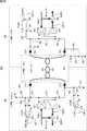
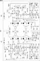
次に図6は、CECライン84、およびHDMI(R)のコネクタの空きピンに接続される信号線を用いて、半二重通信方式によるIP通信を行うHDMI(R)ソース71およびHDMI(R)シンク72の構成を示す図である。なお、図6は、HDMI(R)ソース71およびHDMI(R)シンク72における、半二重通信に関する部分の構成例を示している。また、図6において図3における場合と対応する部分については、同一の符号を付してあり、その説明は適宜省略する。 Next, FIG. 6 shows an HDMI (R)
HDMI(R)ソース71は、トランスミッタ81、切り換え制御部121、およびタイミング制御部122から構成される。また、トランスミッタ81には、変換部131、復号部132、およびスイッチ133が設けられている。 The HDMI (R)
変換部131には、HDMI(R)ソース71とHDMI(R)シンク72との間での双方向のIP通信により、HDMI(R)ソース71からHDMI(R)シンク72に送信されるデータである、Txデータが供給される。Txデータは、たとえば圧縮された画素データや音声データなどとされる。 The
変換部131は、たとえば差動アンプリファイアにより構成され、供給されたTxデータを2つの部分信号からなる差動信号に変換する。また、変換部131は、変換により得られた差動信号をCECライン84、およびトランスミッタ81に設けられた図示せぬコネクタの空きピンに接続される信号線141を介してレシーバ82に送信する。すなわち、変換部131は、変換により得られた差動信号を構成する一方の部分信号をCECライン84、より詳細にはトランスミッタ81に設けられた信号線であって、HDMI(R)ケーブル35のCECライン84に接続される信号線を介してスイッチ133に供給し、差動信号を構成する他方の部分信号を信号線141、より詳細には、トランスミッタ81に設けられた信号線であって、HDMI(R)ケーブル35の信号線141に接続される信号線、および信号線141を介してレシーバ82に供給する。 The
復号部132は、たとえば差動アンプリファイアにより構成され、その入力端子が、CECライン84および信号線141に接続されている。復号部132は、タイミング制御部122の制御に基づいて、CECライン84および信号線141を介してレシーバ82から送信されてきた差動信号、つまりCECライン84上の部分信号および信号線141上の部分信号からなる差動信号を受信し、元のデータであるRxデータに復号して出力する。ここで、Rxデータとは、HDMI(R)ソース71とHDMI(R)シンク72との間での双方向のIP通信により、HDMI(R)シンク72からHDMI(R)ソース71に送信されるデータをいい、たとえば画素データや音声データの送信を要求するコマンドなどとされる。 The
スイッチ133には、データを送信するタイミングにおいて、HDMI(R)ソース71からのCEC信号、または変換部131からのTxデータに対応する差動信号を構成する部分信号が供給され、データを受信するタイミングにおいて、レシーバ82からのCEC信号、またはレシーバ82からのRxデータに対応する差動信号を構成する部分信号が供給される。スイッチ133は、切り換え制御部121からの制御に基づいて、HDMI(R)ソース71からのCEC信号、若しくはレシーバ82からのCEC信号、またはTxデータに対応する差動信号を構成する部分信号、若しくはRxデータに対応する差動信号を構成する部分信号を選択して出力する。 The
すなわち、スイッチ133は、HDMI(R)ソース71がHDMI(R)シンク72にデータを送信するタイミングにおいて、HDMI(R)ソース71から供給されたCEC信号、または変換部131から供給された部分信号のうちのいずれかを選択し、選択したCEC信号または部分信号を、CECライン84を介してレシーバ82に送信する。 That is, the
また、スイッチ133は、HDMI(R)ソース71がHDMI(R)シンク72から送信されてきたデータを受信するタイミングにおいて、CECライン84を介してレシーバ82から送信されてきたCEC信号、またはRxデータに対応する差動信号の部分信号を受信し、受信したCEC信号または部分信号を、HDMI(R)ソース71または復号部132に供給する。 Further, the
切り換え制御部121はスイッチ133を制御して、スイッチ133に供給される信号のうちのいずれかが選択されるようにスイッチ133を切り換える。タイミング制御部122は、復号部132による差動信号の受信のタイミングを制御する。 The switching
また、HDMI(R)シンク72は、レシーバ82、タイミング制御部123、および切り換え制御部124から構成される。さらに、レシーバ82には、変換部134、スイッチ135、および復号部136が設けられている。 The HDMI (R) sink 72 includes a
変換部134は、たとえば差動アンプリファイアにより構成され、変換部134にはRxデータが供給される。変換部134は、タイミング制御部123の制御に基づいて、供給されたRxデータを2つの部分信号からなる差動信号に変換し、変換により得られた差動信号をCECライン84および信号線141を介してトランスミッタ81に送信する。すなわち、変換部134は、変換により得られた差動信号を構成する一方の部分信号をCECライン84、より詳細にはレシーバ82に設けられた信号線であって、HDMI(R)ケーブル35のCECライン84に接続される信号線を介してスイッチ135に供給し、差動信号を構成する他方の部分信号を信号線141、より詳細には、レシーバ82に設けられた信号線であって、HDMI(R)ケーブル35の信号線141に接続される信号線、および信号線141を介してトランスミッタ81に供給する。 The
スイッチ135には、データを受信するタイミングにおいて、トランスミッタ81からのCEC信号、またはトランスミッタ81からのTxデータに対応する差動信号を構成する部分信号が供給され、データを送信するタイミングにおいて、変換部134からのRxデータに対応する差動信号を構成する部分信号、またはHDMI(R)シンク72からのCEC信号が供給される。スイッチ135は、切り換え制御部124からの制御に基づいて、トランスミッタ81からのCEC信号、若しくはHDMI(R)シンク72からのCEC信号、またはTxデータに対応する差動信号を構成する部分信号、若しくはRxデータに対応する差動信号を構成する部分信号を選択して出力する。 The
すなわち、スイッチ135は、HDMI(R)シンク72がHDMI(R)ソース71にデータを送信するタイミングにおいて、HDMI(R)シンク72から供給されたCEC信号、または変換部134から供給された部分信号のうちのいずれかを選択し、選択したCEC信号または部分信号を、CECライン84を介してトランスミッタ81に送信する。 That is, the
また、スイッチ135は、HDMI(R)シンク72がHDMI(R)ソース71から送信されてきたデータを受信するタイミングにおいて、CECライン84を介してトランスミッタ81から送信されてきたCEC信号、またはTxデータに対応する差動信号の部分信号を受信し、受信したCEC信号または部分信号を、HDMI(R)シンク72または復号部136に供給する。 In addition, the
復号部136は、たとえば差動アンプリファイアにより構成され、その入力端子が、CECライン84および信号線141に接続されている。復号部136は、CECライン84および信号線141を介してトランスミッタ81から送信されてきた差動信号、つまりCECライン84上の部分信号および信号線141上の部分信号からなる差動信号を受信し、元のデータであるTxデータに復号して出力する。 The
切り換え制御部124はスイッチ135を制御して、スイッチ135に供給される信号のうちのいずれかが選択されるようにスイッチ135を切り換える。タイミング制御部123は、変換部134による差動信号の送信のタイミングを制御する。 The switching
また、HDMI(R)ソース71およびHDMI(R)シンク72が、CECライン84および空きピンに接続される信号線141と、SDA信号が伝送される信号線およびSCL信号が伝送される信号線とを用いて、全二重通信方式によるIP通信を行う場合、HDMI(R)ソース71およびHDMI(R)シンク72は、たとえば図7に示すように構成される。なお、図7において、図6における場合と対応する部分については、同一の符号を付してあり、その説明は適宜省略する。 Further, the HDMI (R)
HDMI(R)ソース71は、トランスミッタ81、切り換え制御部121、および切り換え制御部171から構成される。また、トランスミッタ81には、変換部131、スイッチ133、スイッチ181、スイッチ182、および復号部183が設けられている。 The HDMI (R)
スイッチ181には、データを送信するタイミングにおいて、HDMI(R)ソース71からのSDA信号が供給され、データを受信するタイミングにおいて、レシーバ82からのSDA信号、またはレシーバ82からのRxデータに対応する差動信号を構成する部分信号が供給される。スイッチ181は、切り換え制御部171からの制御に基づいて、HDMI(R)ソース71からのSDA信号、若しくはレシーバ82からのSDA信号、またはRxデータに対応する差動信号を構成する部分信号を選択して出力する。 The
すなわち、スイッチ181は、HDMI(R)ソース71がHDMI(R)シンク72から送信されてくるデータを受信するタイミングにおいて、SDA信号が伝送される信号線であるSDAライン191を介してレシーバ82から送信されてきたSDA信号、またはRxデータに対応する差動信号の部分信号を受信し、受信したSDA信号または部分信号を、HDMI(R)ソース71または復号部183に供給する。 That is, the
また、スイッチ181は、HDMI(R)ソース71がHDMI(R)シンク72にデータを送信するタイミングにおいて、HDMI(R)ソース71から供給されたSDA信号を、SDAライン191を介してレシーバ82に送信するか、またはレシーバ82に何も送信しない。 In addition, the
スイッチ182には、データを送信するタイミングにおいて、HDMI(R)ソース71からのSCL信号が供給され、データを受信するタイミングにおいて、レシーバ82からのRxデータに対応する差動信号を構成する部分信号が供給される。スイッチ182は、切り換え制御部171からの制御に基づいて、SCL信号またはRxデータに対応する差動信号を構成する部分信号のうちのいずれかを選択して出力する。 The
すなわち、スイッチ182は、HDMI(R)ソース71がHDMI(R)シンク72から送信されてくるデータを受信するタイミングにおいて、SCL信号が伝送される信号線であるSCLライン192を介してレシーバ82から送信されてきた、Rxデータに対応する差動信号の部分信号を受信し、受信した部分信号を復号部183に供給するか、または何も受信しない。 That is, the
また、スイッチ182は、HDMI(R)ソース71がHDMI(R)シンク72にデータを送信するタイミングにおいて、HDMI(R)ソース71から供給されたSCL信号を、SCLライン192を介してレシーバ82に送信するか、または何も送信しない。 In addition, the
復号部183は、たとえば差動アンプリファイアにより構成され、その入力端子が、SDAライン191およびSCLライン192に接続されている。復号部183は、SDAライン191およびSCLライン192を介してレシーバ82から送信されてきた差動信号、つまりSDAライン191上の部分信号およびSCLライン192上の部分信号からなる差動信号を受信し、元のデータであるRxデータに復号して出力する。 The
切り換え制御部171はスイッチ181およびスイッチ182を制御して、スイッチ181およびスイッチ182のそれぞれについて、供給される信号のうちのいずれかが選択されるようにスイッチ181およびスイッチ182を切り換える。 The switching
また、HDMI(R)シンク72は、レシーバ82、切り換え制御部124、および切り換え制御部172から構成される。さらに、レシーバ82には、スイッチ135、復号部136、変換部184、スイッチ185、およびスイッチ186が設けられている。 The HDMI (R) sink 72 includes a
変換部184は、たとえば差動アンプリファイアにより構成され、変換部184にはRxデータが供給される。変換部184は、供給されたRxデータを2つの部分信号からなる差動信号に変換し、変換により得られた差動信号をSDAライン191およびSCLライン192を介してトランスミッタ81に送信する。すなわち、変換部184は、変換により得られた差動信号を構成する一方の部分信号をスイッチ185を介してトランスミッタ81に送信し、差動信号を構成する他方の部分信号をスイッチ186を介してトランスミッタ81に送信する。 The
スイッチ185には、データを送信するタイミングにおいて、変換部184からのRxデータに対応する差動信号を構成する部分信号、またはHDMI(R)シンク72からのSDA信号が供給され、データを受信するタイミングにおいて、トランスミッタ81からのSDA信号が供給される。スイッチ185は、切り換え制御部172からの制御に基づいて、HDMI(R)シンク72からのSDA信号、若しくはトランスミッタ81からのSDA信号、またはRxデータに対応する差動信号を構成する部分信号を選択して出力する。 The
すなわち、スイッチ185は、HDMI(R)シンク72がHDMI(R)ソース71から送信されてくるデータを受信するタイミングにおいて、SDAライン191を介してトランスミッタ81から送信されてきたSDA信号を受信し、受信したSDA信号をHDMI(R)シンク72に供給するか、または何も受信しない。 That is, the
また、スイッチ185は、HDMI(R)シンク72がHDMI(R)ソース71にデータを送信するタイミングにおいて、HDMI(R)シンク72から供給されたSDA信号、または変換部184から供給された部分信号を、SDAライン191を介してトランスミッタ81に送信する。 The
スイッチ186には、データを送信するタイミングにおいて、変換部184からの、Rxデータに対応する差動信号を構成する部分信号が供給され、データを受信するタイミングにおいて、トランスミッタ81からのSCL信号が供給される。スイッチ186は、切り換え制御部172からの制御に基づいて、Rxデータに対応する差動信号を構成する部分信号、またはSCL信号のうちのいずれかを選択して出力する。 The
すなわち、スイッチ186は、HDMI(R)シンク72がHDMI(R)ソース71から送信されてくるデータを受信するタイミングにおいて、SCLライン192を介してトランスミッタ81から送信されてきたSCL信号を受信し、受信したSCL信号をHDMI(R)シンク72に供給するか、または何も受信しない。 That is, the
また、スイッチ186は、HDMI(R)シンク72がHDMI(R)ソース71にデータを送信するタイミングにおいて、変換部184から供給された部分信号を、SCLライン192を介してトランスミッタ81に送信するか、または何も送信しない。 Further, the
切り換え制御部172はスイッチ185およびスイッチ186を制御して、スイッチ185およびスイッチ186のそれぞれについて、供給される信号のうちのいずれかが選択されるようにスイッチ185およびスイッチ186を切り換える。 The switching
ところで、HDMI(R)ソース71とHDMI(R)シンク72とがIP通信を行う場合に、半二重通信が可能であるか、全二重通信が可能であるかは、HDMI(R)ソース71およびHDMI(R)シンク72のそれぞれの構成によって定まる。そこで、HDMI(R)ソース71は、HDMI(R)シンク72から受信したE-EDIDを参照して、半二重通信を行うか、全二重通信を行うか、またはCEC信号の授受による双方向通信を行うかの判定を行う。 By the way, when the HDMI (R)
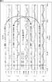
HDMI(R)ソース71が受信するE-EDIDは、たとえば図8に示すように、基本ブロックと拡張ブロックとからなる。 The E-EDID received by the HDMI (R)
E-EDIDの基本ブロックの先頭には、“E-EDID1.3 Basic Structure”で表されるE-EDID1.3の規格で定められたデータが配置され、続いて“Preferred timing”で表される従来のEDIDとの互換性を保つためのタイミング情報、および“2nd timing”で表される従来のEDIDとの互換性を保つための“Preferred timing”とは異なるタイミング情報が配置されている。 At the beginning of the basic block of E-EDID, data defined by the E-EDID1.3 standard represented by “E-EDID1.3 Basic Structure” is placed, followed by “Preferred timing” Timing information for maintaining compatibility with the conventional EDID and timing information different from “Preferred timing” for maintaining compatibility with the conventional EDID represented by “2nd timing” are arranged.
また、基本ブロックには、“2nd timing”に続いて、“Monitor NAME”で表される表示装置の名前を示す情報、および“Monitor Range Limits”で表される、アスペクト比が4:3および16:9である場合についての表示可能な画素数を示す情報が順番に配置されている。 The basic block includes information indicating the name of the display device represented by “Monitor NAME” following “2nd timing”, and aspect ratios of 4: 3 and 16 represented by “Monitor Range Limits”. Information indicating the number of displayable pixels in the case of: 9 is arranged in order.
これに対して、拡張ブロックの先頭には、“Speaker Allocation”で表される左右のスピーカに関する情報が配置され、続いて“VIDEO SHORT”で表される、表示可能な画像サイズ、フレームレート、インターレースであるかプログレッシブであるかを示す情報、アスペクト比などの情報が記述されたデータ、“AUDIO SHORT”で表される、再生可能な音声コーデック方式、サンプリング周波数、カットオフ帯域、コーデックビット数などの情報が記述されたデータ、および“Speaker Allocation”で表される左右のスピーカに関する情報が順番に配置されている。 On the other hand, information about the left and right speakers represented by “Speaker Allocation” is placed at the beginning of the extension block, followed by the displayable image size, frame rate, and interlace represented by “VIDEO SHORT”. Information indicating whether the image is progressive or progressive, data describing information such as aspect ratio, reproducible audio codec method, sampling frequency, cut-off band, codec bit number, etc. represented by “AUDIO SHORT” Data describing the information and information on the left and right speakers represented by “Speaker Allocation” are arranged in order.
また、拡張ブロックには、“Speaker Allocation”に続いて、“Vender Specific”で表されるメーカごとに固有に定義されたデータ、“3rd timing”で表される従来のEDIDとの互換性を保つためのタイミング情報、および“4th timing”で表される従来のEDIDとの互換性を保つためのタイミング情報が配置されている。 In addition, the extension block maintains compatibility with the conventional EDID represented by “3rd timing”, the data defined uniquely for each manufacturer represented by “Vender Specific” following “Speaker Allocation”. Timing information for maintaining compatibility with the conventional EDID represented by “4th timing” is arranged.
さらに、“Vender Specific”で表されるデータは、図9に示すデータ構造となっている。すなわち、“Vender Specific”で表されるデータには、1バイトのブロックである第0ブロック乃至第Nブロックが設けられている。 Furthermore, the data represented by “Vender Specific” has a data structure shown in FIG. That is, the data represented by “Vender Specific” includes a 0th block to an Nth block which are 1-byte blocks.
“Vender Specific”で表されるデータの先頭に配置された第0ブロックには、“Vendor-Specific tag code(=3)”で表されるデータ“Vender Specific”のデータ領域を示すヘッダ、および“Length(=N)”で表されるデータ“Vender Specific”の長さを示す情報が配置される。 The 0th block arranged at the head of the data represented by “Vender Specific” includes a header indicating a data area of data “Vender Specific” represented by “Vendor-Specific tag code (= 3)”, and “ Information indicating the length of the data “Vender Specific” represented by “Length (= N)” is arranged.
また、第1ブロック乃至第3ブロックには、“24bit IEEE Registration Identifier(0x000C03)LSB first”で表されるHDMI(R)用として登録された番号“0x000C03“を示す情報が配置される。さらに、第4ブロックおよび第5ブロックには、”A“、”B“、”C“、および”D“のそれぞれにより表される、24bitのシンク機器の物理アドレスを示す情報が配置される。 Also, information indicating the number “0x000C03” registered for HDMI (R) represented by “24bit IEEE Registration Identifier (0x000C03) LSB first” is arranged in the first block to the third block. Further, in the fourth block and the fifth block, information indicating the physical address of the 24-bit sink device represented by “A”, “B”, “C”, and “D” is arranged.
第6ブロックには、“Supports-AI”で表されるシンク機器が対応している機能を示すフラグ、“DC-48bit”、“DC-36bit”、および“DC-30bit”のそれぞれで表される1ピクセル当たりのビット数を指定する情報のそれぞれ、“DC-Y444”で表される、シンク機器がYCbCr4:4:4の画像の伝送に対応しているかを示すフラグ、および“DVI-Dual”で表される、シンク機器がデュアルDVI(Digital Visual Interface)に対応しているかを示すフラグが配置されている。 In the sixth block, a flag indicating a function supported by the sink device represented by “Supports-AI”, “DC-48 bit”, “DC-36 bit”, and “DC-30 bit” are indicated. Each of the information that specifies the number of bits per pixel, a flag indicating whether the sink device supports YCbCr4: 4: 4 image transmission, represented by “DC-Y444”, and “DVI-Dual A flag indicating whether the sink device is compatible with dual DVI (Digital Visual Interface) is arranged.
また、第7ブロックには、“Max-TMDS-Clock”で表されるTMDSのピクセルクロックの最大の周波数を示す情報が配置される。さらに、第8ブロックには、“Latency”で表される映像と音声の遅延情報の有無を示すフラグ、“Full Duplex”で表される全二重通信が可能であるかを示す全二重フラグ、および“Half Duplex”で表される半二重通信が可能であるかを示す半二重フラグが配置されている。 In the seventh block, information indicating the maximum frequency of the TMDS pixel clock represented by “Max-TMDS-Clock” is arranged. Further, the eighth block includes a flag indicating the presence / absence of video and audio delay information represented by “Latency”, and a full-duplex flag representing whether full-duplex communication is possible represented by “Full Duplex”. And a half-duplex flag indicating whether or not half-duplex communication represented by “Half Duplex” is possible.
ここで、たとえばセットされている(たとえば“1”に設定されている)全二重フラグは、HDMI(R)シンク72が全二重通信を行う機能を有している、つまり図7に示した構成とされることを示しており、リセットされている(たとえば“0”に設定されている)全二重フラグは、HDMI(R)シンク72が全二重通信を行う機能を有していないことを示している。 Here, for example, the full-duplex flag that is set (for example, set to “1”) has a function for the HDMI (R) sink 72 to perform full-duplex communication, that is, as shown in FIG. The full-duplex flag that is reset (for example, set to “0”) has a function for the HDMI (R) sink 72 to perform full-duplex communication. It shows no.
同様に、セットされている(たとえば“1”に設定されている)半二重フラグは、HDMI(R)シンク72が半二重通信を行う機能を有している、つまり図6に示した構成とされることを示しており、リセットされている(たとえば“0”に設定されている)半二重フラグは、HDMI(R)シンク72が半二重通信を行う機能を有していないことを示している。 Similarly, the half-duplex flag that is set (for example, set to “1”) has a function for the HDMI (R) sink 72 to perform half-duplex communication, that is, as shown in FIG. The half-duplex flag being reset (for example, set to “0”) does not have a function for the HDMI (R) sink 72 to perform half-duplex communication. It is shown that.
また、“Vender Specific”で表されるデータの第9ブロックには、“Video Latency”で表されるプログレッシブの映像の遅延時間データが配置され、第10ブロックには、“Audio Latency”で表される、プログレッシブの映像に付随する音声の遅延時間データが配置される。さらに、第11ブロックには、“Interlaced Video Latency”で表されるインターレースの映像の遅延時間データが配置され、第12ブロックには、“Interlaced Audio Latency”で表される、インターレースの映像に付随する音声の遅延時間データが配置される。 In addition, in the ninth block of data represented by “Vender Specific”, the delay time data of progressive video represented by “Video Latency” is arranged, and in the tenth block, represented by “Audio Latency”. The audio delay time data associated with the progressive video is arranged. Further, interlaced video delay time data represented by “Interlaced Video Latency” is arranged in the eleventh block, and an interlaced video represented by “Interlaced Audio Latency” is attached to the twelfth block. Audio delay time data is arranged.
HDMI(R)ソース71は、HDMI(R)シンク72から受信したE-EDIDに含まれている全二重フラグおよび半二重フラグに基づいて、半二重通信を行うか、全二重通信を行うか、またはCEC信号の授受による双方向通信を行うかの判定を行い、その判定結果にしたがって、HDMI(R)シンク72との双方向の通信を行う。 The HDMI (R)
たとえば、HDMI(R)ソース71が図6に示した構成とされている場合、HDMI(R)ソース71は、図6に示したHDMI(R)シンク72とは半二重通信を行うことができるが、図7に示したHDMI(R)シンク72とは半二重通信を行うことができない。 For example, when the HDMI (R)
そこで、HDMI(R)ソース71は、HDMI(R)ソース71が設けられた電子機器の電源がオンされると通信処理を開始し、HDMI(R)ソース71に接続されたHDMI(R)シンク72の有する機能に応じた双方向の通信を行う。 Therefore, the HDMI (R)
以下、図10のフローチャートを参照して、図6に示したHDMI(R)ソース71による通信処理について説明する。 Hereinafter, with reference to the flowchart of FIG. 10, the communication process by the HDMI (R)
ステップS11において、HDMI(R)ソース71は、HDMI(R)ソース71に新たな電子機器が接続されたか否かを判定する。たとえば、HDMI(R)ソース71は、信号線86が接続されるHot Plug Detectと呼ばれるピンに対して付加された電圧の大きさに基づいて、HDMI(R)シンク72が設けられた新たな電子機器が接続されたか否かを判定する。 In step S <b> 11, the HDMI (R)
ステップS11において、新たな電子機器が接続されていないと判定された場合、通信は行われないので、通信処理は終了する。 If it is determined in step S11 that a new electronic device is not connected, communication is not performed, and the communication process ends.
これに対して、ステップS11において、新たな電子機器が接続されたと判定された場合、ステップS12において、切り換え制御部121はスイッチ133を制御し、データの送信時においてHDMI(R)ソース71からのCEC信号が選択され、データの受信時においてレシーバ82からのCEC信号が選択されるように、スイッチ133を切り換える。 On the other hand, if it is determined in step S11 that a new electronic device has been connected, in step S12, the switching
ステップS13において、HDMI(R)ソース71は、DDC83を介してHDMI(R)シンク72から送信されてきたE-EDIDを受信する。すなわち、HDMI(R)シンク72は、HDMI(R)ソース71の接続を検出するとEDIDROM85からE-EDIDを読み出し、読み出したE-EDIDを、DDC83を介してHDMI(R)ソース71に送信するので、HDMI(R)ソース71は、HDMI(R)シンク72から送信されてきたE-EDIDを受信する。 In step S <b> 13, the HDMI (R)
ステップS14において、HDMI(R)ソース71は、HDMI(R)シンク72との半二重通信が可能であるか否かを判定する。すなわち、HDMI(R)ソース71は、HDMI(R)シンク72から受信したE-EDIDを参照して、図9の半二重フラグ“Half Duplex”がセットされているか否かを判定し、たとえば半二重フラグがセットされている場合、HDMI(R)ソース71は、半二重通信方式による双方向のIP通信、つまり半二重通信が可能であると判定する。 In step S <b> 14, the HDMI (R)
ステップS14において、半二重通信が可能であると判定された場合、ステップS15において、HDMI(R)ソース71は、双方向の通信に用いるチャンネルを示すチャンネル情報として、CECライン84および信号線141を用いた半二重通信方式によるIP通信を行う旨の信号を、スイッチ133およびCECライン84を介してレシーバ82に送信する。 If it is determined in step S14 that half-duplex communication is possible, in step S15, the HDMI (R)
すなわち、半二重フラグがセットされている場合、HDMI(R)ソース71は、HDMI(R)シンク72が図6に示した構成であり、CECライン84および信号線141を用いた半二重通信が可能であることが分かるので、チャンネル情報をHDMI(R)シンク72に送信して、半二重通信を行う旨を通知する。 That is, when the half-duplex flag is set, the HDMI (R)
ステップS16において、切り換え制御部121はスイッチ133を制御し、データの送信時において変換部131からのTxデータに対応する差動信号が選択され、データの受信時においてレシーバ82からのRxデータに対応する差動信号が選択されるように、スイッチ133を切り換える。 In step S16, the switching
ステップS17において、HDMI(R)ソース71の各部は、半二重通信方式により、HDMI(R)シンク72との双方向のIP通信を行い、通信処理は終了する。すなわち、データの送信時において、変換部131は、HDMI(R)ソース71から供給されたTxデータを差動信号に変換し、変換により得られた差動信号を構成する部分信号のうちの一方をスイッチ133に供給し、他方の部分信号を信号線141を介してレシーバ82に送信する。スイッチ133は、変換部131から供給された部分信号を、CECライン84を介してレシーバ82に送信する。これにより、Txデータに対応する差動信号がHDMI(R)ソース71からHDMI(R)シンク72に送信される。 In step S17, each part of the HDMI (R)
また、データの受信時において、復号部132は、レシーバ82から送信されてきたRxデータに対応する差動信号を受信する。すなわち、スイッチ133は、CECライン84を介してレシーバ82から送信されてきた、Rxデータに対応する差動信号の部分信号を受信し、受信した部分信号を復号部132に供給する。復号部132は、スイッチ133から供給された部分信号、および信号線141を介してレシーバ82から供給された部分信号からなる差動信号を、タイミング制御部122の制御に基づいて、元のデータであるRxデータに復号し、HDMI(R)ソース71に出力する。 At the time of data reception, the
これにより、HDMI(R)ソース71は、HDMI(R)シンク72と制御データや画素データ、音声データなど、各種のデータの授受を行う。 Thereby, the HDMI (R)
また、ステップS14において、半二重通信が可能でないと判定された場合、ステップS18において、HDMI(R)ソース71の各部は、CEC信号の送受信を行うことでHDMI(R)シンク72との双方向の通信を行い、通信処理は終了する。 If it is determined in step S14 that half-duplex communication is not possible, in step S18, each part of the HDMI (R)
すなわち、データの送信時において、HDMI(R)ソース71は、スイッチ133およびCECライン84を介して、CEC信号をレシーバ82に送信し、データの受信時において、HDMI(R)ソース71は、スイッチ133およびCECライン84を介してレシーバ82から送信されてきたCEC信号を受信することで、HDMI(R)シンク72との制御データの授受を行う。 That is, at the time of data transmission, the HDMI (R)
このようにして、HDMI(R)ソース71は、半二重フラグを参照し、半二重通信が可能なHDMI(R)シンク72と、CECライン84および信号線141を用いて半二重通信を行う。 In this manner, the HDMI (R)
このように、スイッチ133を切り換えて送信するデータ、および受信するデータを選択し、HDMI(R)シンク72と、CECライン84および信号線141を用いた半二重通信、つまり半二重通信方式によるIP通信を行うことで、従来のHDMI(R)との互換性を保ちつつ、高速の双方向通信を行うことができる。 In this way, the
また、HDMI(R)ソース71と同様に、HDMI(R)シンク72も、HDMI(R)シンク72が設けられた電子機器の電源がオンされると通信処理を開始し、HDMI(R)ソース71との双方向の通信を行う。 Similarly to the HDMI (R)
以下、図11のフローチャートを参照して、図6に示したHDMI(R)シンク72による通信処理について説明する。 The communication process performed by the HDMI (R) sink 72 shown in FIG. 6 will be described below with reference to the flowchart of FIG.
ステップS41において、HDMI(R)シンク72は、HDMI(R)シンク72に新たな電子機器が接続されたか否かを判定する。たとえば、HDMI(R)シンク72は、信号線86が接続されたHot Plug Detectと呼ばれるピンに対して付加された電圧の大きさに基づいて、HDMI(R)ソース71が設けられた新たな電子機器が接続されたか否かを判定する。 In step S <b> 41, the HDMI (R) sink 72 determines whether a new electronic device is connected to the HDMI (R) sink 72. For example, the HDMI (R) sink 72 is a new electronic device provided with the HDMI (R)
ステップS41において、新たな電子機器が接続されていないと判定された場合、通信は行われないので、通信処理は終了する。 If it is determined in step S41 that a new electronic device is not connected, communication is not performed, and the communication process ends.
これに対して、ステップS41において、新たな電子機器が接続されたと判定された場合、ステップS42において、切り換え制御部124はスイッチ135を制御し、データの送信時においてHDMI(R)シンク72からのCEC信号が選択され、データの受信時においてトランスミッタ81からのCEC信号が選択されるように、スイッチ135を切り換える。 On the other hand, if it is determined in step S41 that a new electronic device has been connected, in step S42, the switching
ステップS43において、HDMI(R)シンク72は、EDIDROM85からE-EDIDを読み出し、読み出したE-EDIDを、DDC83を介してHDMI(R)ソース71に送信する。 In step S 43, the HDMI (R) sink 72 reads the E-EDID from the EDIDROM 85 and transmits the read E-EDID to the HDMI (R)
ステップS44において、HDMI(R)シンク72は、HDMI(R)ソース71から送信されてきたチャンネル情報を受信したか否かを判定する。 In step S44, the HDMI (R) sink 72 determines whether channel information transmitted from the HDMI (R)
すなわち、HDMI(R)ソース71からは、HDMI(R)ソース71およびHDMI(R)シンク72が有する機能に応じて、双方向の通信のチャンネルを示すチャンネル情報が送信されてくる。たとえば、HDMI(R)ソース71が図6に示すように構成される場合、HDMI(R)ソース71とHDMI(R)シンク72とは、CECライン84および信号線141を用いた半二重通信が可能であるので、HDMI(R)ソース71からHDMI(R)シンク72には、CECライン84および信号線141を用いたIP通信を行う旨のチャンネル情報が送信されてくる。HDMI(R)シンク72は、スイッチ135およびCECライン84を介してHDMI(R)ソース71から送信されてきたチャンネル情報を受信し、チャンネル情報を受信したと判定する。 That is, channel information indicating a bidirectional communication channel is transmitted from the HDMI (R)
これに対して、HDMI(R)ソース71が半二重通信を行う機能を有していない場合、HDMI(R)ソース71からHDMI(R)シンク72には、チャンネル情報が送信されてこないので、HDMI(R)シンク72は、チャンネル情報を受信していないと判定する。 On the other hand, when the HDMI (R)
ステップS44において、チャンネル情報を受信したと判定された場合、処理はステップS45に進み、切り換え制御部124は、スイッチ135を制御し、データの送信時において変換部134からのRxデータに対応する差動信号が選択され、データの受信時においてトランスミッタ81からのTxデータに対応する差動信号が選択されるように、スイッチ135を切り換える。 If it is determined in step S44 that the channel information has been received, the process proceeds to step S45, where the switching
ステップS46において、HDMI(R)シンク72の各部は、半二重通信方式により、HDMI(R)ソース71との双方向のIP通信を行い、通信処理は終了する。すなわち、データの送信時において、変換部134は、タイミング制御部123の制御に基づいてHDMI(R)シンク72から供給されたRxデータを差動信号に変換し、変換により得られた差動信号を構成する部分信号のうちの一方をスイッチ135に供給し、他方の部分信号を信号線141を介してトランスミッタ81に送信する。スイッチ135は、変換部134から供給された部分信号を、CECライン84を介してトランスミッタ81に送信する。これにより、Rxデータに対応する差動信号がHDMI(R)シンク72からHDMI(R)ソース71に送信される。 In step S46, each part of the HDMI (R) sink 72 performs bidirectional IP communication with the HDMI (R)
また、データの受信時において、復号部136は、トランスミッタ81から送信されてきたTxデータに対応する差動信号を受信する。すなわち、スイッチ135は、CECライン84を介してトランスミッタ81から送信されてきた、Txデータに対応する差動信号の部分信号を受信し、受信した部分信号を復号部136に供給する。復号部136は、スイッチ135から供給された部分信号、および信号線141を介してトランスミッタ81から供給された部分信号からなる差動信号を元のデータであるTxデータに復号し、HDMI(R)シンク72に出力する。 At the time of data reception, the
これにより、HDMI(R)シンク72は、HDMI(R)ソース71と制御データや画素データ、音声データなど、各種のデータの授受を行う。 Accordingly, the HDMI (R) sink 72 exchanges various data such as control data, pixel data, and audio data with the HDMI (R)
また、ステップS44において、チャンネル情報を受信していないと判定された場合、ステップS47において、HDMI(R)シンク72の各部は、CEC信号の送受信を行うことでHDMI(R)ソース71との双方向の通信を行い、通信処理は終了する。 If it is determined in step S44 that the channel information has not been received, in step S47, each part of the HDMI (R) sink 72 transmits / receives the CEC signal to both the HDMI (R)
すなわち、データの送信時において、HDMI(R)シンク72は、スイッチ135およびCECライン84を介して、CEC信号をトランスミッタ81に送信し、データの受信時において、HDMI(R)シンク72は、スイッチ135およびCECライン84を介してトランスミッタ81から送信されてきたCEC信号を受信することで、HDMI(R)ソース71との制御データの授受を行う。 That is, at the time of data transmission, the HDMI (R) sink 72 transmits a CEC signal to the
このようにして、HDMI(R)シンク72は、チャンネル情報を受信すると、HDMI(R)シンク72と、CECライン84および信号線141を用いて半二重通信を行う。 In this manner, when receiving the channel information, the HDMI (R) sink 72 performs half-duplex communication using the HDMI (R) sink 72, the
このように、HDMI(R)シンク72がスイッチ135を切り換えて送信するデータ、および受信するデータを選択し、HDMI(R)ソース71とCECライン84および信号線141を用いた半二重通信を行うことで、従来のHDMI(R)との互換性を保ちつつ、高速の双方向通信を行うことができる。 In this way, the HDMI (R) sink 72 switches the
また、HDMI(R)ソース71が図7に示す構成とされる場合、HDMI(R)ソース71は、通信処理において、E-EDIDに含まれる全二重フラグに基づいてHDMI(R)シンク72が全二重通信を行う機能を有しているかを判定し、その判定結果に応じた双方向の通信を行う。 Further, when the HDMI (R)
以下、図12のフローチャートを参照して、図7に示したHDMI(R)ソース71による通信処理について説明する。 Hereinafter, the communication process by the HDMI (R)
ステップS71において、HDMI(R)ソース71は、HDMI(R)ソース71に新たな電子機器が接続されたか否かを判定する。ステップS71において、新たな電子機器が接続されていないと判定された場合、通信は行われないので、通信処理は終了する。 In step S <b> 71, the HDMI (R)
これに対して、ステップS71において、新たな電子機器が接続されたと判定された場合、ステップS72において、切り換え制御部171は、スイッチ181およびスイッチ182を制御し、データの送信時において、スイッチ181によりHDMI(R)ソース71からのSDA信号が選択され、スイッチ182によりHDMI(R)ソース71からのSCL信号が選択され、さらにデータの受信時において、スイッチ181によりレシーバ82からのSDA信号が選択されるように、スイッチ181およびスイッチ182を切り換える。 On the other hand, when it is determined in step S71 that a new electronic device has been connected, in step S72, the switching
ステップS73において、切り換え制御部121はスイッチ133を制御し、データの送信時においてHDMI(R)ソース71からのCEC信号が選択され、データの受信時においてレシーバ82からのCEC信号が選択されるように、スイッチ133を切り換える。 In step S73, the switching
ステップS74において、HDMI(R)ソース71は、DDC83のSDAライン191を介してHDMI(R)シンク72から送信されてきたE-EDIDを受信する。すなわち、HDMI(R)シンク72は、HDMI(R)ソース71の接続を検出するとEDIDROM85からE-EDIDを読み出し、読み出したE-EDIDを、DDC83のSDAライン191を介してHDMI(R)ソース71に送信するので、HDMI(R)ソース71は、HDMI(R)シンク72から送信されてきたE-EDIDを受信する。 In step S 74, the HDMI (R)
ステップS75において、HDMI(R)ソース71は、HDMI(R)シンク72との全二重通信が可能であるか否かを判定する。すなわち、HDMI(R)ソース71は、HDMI(R)シンク72から受信したE-EDIDを参照して、図9の全二重フラグ“Full Duplex”がセットされているか否かを判定し、たとえば全二重フラグがセットされている場合、HDMI(R)ソース71は、全二重通信方式による双方向のIP通信、つまり全二重通信が可能であると判定する。 In step S75, the HDMI (R)
ステップS75において、全二重通信が可能であると判定された場合、ステップS76において、切り換え制御部171は、スイッチ181およびスイッチ182を制御し、データの受信時において、レシーバ82からのRxデータに対応する差動信号が選択されるようにスイッチ181およびスイッチ182を切り換える。 If it is determined in step S75 that full-duplex communication is possible, in step S76, the switching
すなわち、切り換え制御部171は、データの受信時において、レシーバ82から送信されてくる、Rxデータに対応した差動信号を構成する部分信号のうち、SDAライン191を介して送信されてくる部分信号がスイッチ181により選択され、SCLライン192を介して送信されてくる部分信号がスイッチ182により選択されるように、スイッチ181およびスイッチ182を切り換える。 That is, the switching
DDC83を構成するSDAライン191およびSCLライン192は、HDMI(R)シンク72からHDMI(R)ソース71にE-EDIDが送信された後は利用されないので、つまりSDAライン191およびSCLライン192を介したSDA信号やSCL信号の送受信は行われないので、スイッチ181およびスイッチ182を切り換えて、SDAライン191およびSCLライン192を、全二重通信によるRxデータの伝送路として利用することができる。 The
ステップS77において、HDMI(R)ソース71は、双方向の通信のチャンネルを示すチャンネル情報として、CECライン84および信号線141と、SDAライン191およびSCLライン192とを用いた全二重通信方式によるIP通信を行う旨の信号を、スイッチ133およびCECライン84を介してレシーバ82に送信する。 In step S77, the HDMI (R)
すなわち、全二重フラグがセットされている場合、HDMI(R)ソース71は、HDMI(R)シンク72が図7に示した構成であり、CECライン84および信号線141と、SDAライン191およびSCLライン192とを用いた全二重通信が可能であることが分かるので、チャンネル情報をHDMI(R)シンク72に送信して、全二重通信を行う旨を通知する。 That is, when the full-duplex flag is set, the HDMI (R)
ステップS78において、切り換え制御部121はスイッチ133を制御し、データの送信時において変換部131からのTxデータに対応する差動信号が選択されるように、スイッチ133を切り換える。すなわち、切り換え制御部121は、変換部131からスイッチ133に供給された、Txデータに対応する差動信号の部分信号が選択されるようにスイッチ133を切り換える。 In step S78, the switching
ステップS79において、HDMI(R)ソース71の各部は、全二重通信方式により、HDMI(R)シンク72との双方向のIP通信を行い、通信処理は終了する。すなわち、データの送信時において、変換部131は、HDMI(R)ソース71から供給されたTxデータを差動信号に変換し、変換により得られた差動信号を構成する部分信号のうちの一方をスイッチ133に供給し、他方の部分信号を信号線141を介してレシーバ82に送信する。スイッチ133は、変換部131から供給された部分信号を、CECライン84を介してレシーバ82に送信する。これにより、Txデータに対応する差動信号がHDMI(R)ソース71からHDMI(R)シンク72に送信される。 In step S79, each part of the HDMI (R)
また、データの受信時において、復号部183は、レシーバ82から送信されてきたRxデータに対応する差動信号を受信する。すなわち、スイッチ181は、SDAライン191を介してレシーバ82から送信されてきた、Rxデータに対応する差動信号の部分信号を受信し、受信した部分信号を復号部183に供給する。また、スイッチ182は、SCLライン192を介してレシーバ82から送信されてきた、Rxデータに対応する差動信号の他方の部分信号を受信し、受信した部分信号を復号部183に供給する。復号部183は、スイッチ181およびスイッチ182から供給された部分信号からなる差動信号を、元のデータであるRxデータに復号し、HDMI(R)ソース71に出力する。 At the time of data reception, the
これにより、HDMI(R)ソース71は、HDMI(R)シンク72と制御データや画素データ、音声データなど、各種のデータの授受を行う。 Thereby, the HDMI (R)
また、ステップS75において、全二重通信が可能でないと判定された場合、ステップS80において、HDMI(R)ソース71の各部は、CEC信号の送受信を行うことでHDMI(R)シンク72との双方向の通信を行い、通信処理は終了する。 If it is determined in step S75 that full-duplex communication is not possible, in step S80, each part of the HDMI (R)
すなわち、データの送信時において、HDMI(R)ソース71は、スイッチ133およびCECライン84を介して、CEC信号をレシーバ82に送信し、データの受信時において、HDMI(R)ソース71は、スイッチ133およびCECライン84を介してレシーバ82から送信されてきたCEC信号を受信することで、HDMI(R)シンク72との制御データの授受を行う。 That is, at the time of data transmission, the HDMI (R)
このようにして、HDMI(R)ソース71は、全二重フラグを参照し、全二重通信が可能なHDMI(R)シンク72と、CECライン84および信号線141、並びにSDAライン191およびSCLライン192を用いて全二重通信を行う。 In this way, the HDMI (R)
このように、スイッチ133、スイッチ181、およびスイッチ182を切り換えて送信するデータ、および受信するデータを選択し、HDMI(R)シンク72とCECライン84および信号線141、並びにSDAライン191およびSCLライン192を用いた全二重通信を行うことで、従来のHDMI(R)との互換性を保ちつつ、高速の双方向通信を行うことができる。 In this way, the
また、HDMI(R)シンク72が図7に示した構成とされる場合においても、HDMI(R)シンク72は、図6に示したHDMI(R)シンク72における場合と同様に、通信処理を行って、HDMI(R)ソース71との双方向の通信を行う。 Further, even when the HDMI (R) sink 72 has the configuration shown in FIG. 7, the HDMI (R) sink 72 performs the communication process in the same manner as in the HDMI (R) sink 72 shown in FIG. And bidirectional communication with the HDMI (R)
以下、図13のフローチャートを参照して、図7に示したHDMI(R)シンク72による通信処理について説明する。 The communication process performed by the HDMI (R) sink 72 shown in FIG. 7 will be described below with reference to the flowchart of FIG.
ステップS111において、HDMI(R)シンク72は、HDMI(R)シンク72に新たな電子機器が接続されたか否かを判定する。ステップS111において、新たな電子機器が接続されていないと判定された場合、通信は行われないので、通信処理は終了する。 In step S <b> 111, the HDMI (R) sink 72 determines whether a new electronic device is connected to the HDMI (R) sink 72. If it is determined in step S111 that a new electronic device is not connected, communication is not performed, and the communication process ends.
これに対して、ステップS111において、新たな電子機器が接続されたと判定された場合、ステップS112において、切り換え制御部172は、スイッチ185およびスイッチ186を制御し、データの送信時において、スイッチ185によりHDMI(R)シンク72からのSDA信号が選択され、さらにデータの受信時において、スイッチ185によりトランスミッタ81からのSDA信号が選択され、スイッチ186によりトランスミッタ81からのSCL信号が選択されるように、スイッチ185およびスイッチ186を切り換える。 On the other hand, when it is determined in step S111 that a new electronic device has been connected, in step S112, the switching
ステップS113において、切り換え制御部124はスイッチ135を制御し、データの送信時においてHDMI(R)シンク72からのCEC信号が選択され、データの受信時においてトランスミッタ81からのCEC信号が選択されるように、スイッチ135を切り換える。 In step S113, the switching
ステップS114において、HDMI(R)シンク72は、EDIDROM85からE-EDIDを読み出し、読み出したE-EDIDを、スイッチ185およびDDC83のSDAライン191を介してHDMI(R)ソース71に送信する。 In step S114, the HDMI (R) sink 72 reads the E-EDID from the
ステップS115において、HDMI(R)シンク72は、HDMI(R)ソース71から送信されてきたチャンネル情報を受信したか否かを判定する。 In step S115, the HDMI (R) sink 72 determines whether channel information transmitted from the HDMI (R)
すなわち、HDMI(R)ソース71からは、HDMI(R)ソース71およびHDMI(R)シンク72が有する機能に応じて、双方向の通信のチャンネルを示すチャンネル情報が送信されてくる。たとえば、HDMI(R)ソース71が図7に示すように構成される場合、HDMI(R)ソース71とHDMI(R)シンク72とは全二重通信が可能であるので、HDMI(R)ソース71からHDMI(R)シンク72には、CECライン84および信号線141と、SDAライン191およびSCLライン192とを用いた全二重通信方式によるIP通信を行う旨のチャンネル情報が送信されてくるので、HDMI(R)シンク72は、スイッチ135およびCECライン84を介してHDMI(R)ソース71から送信されてきたチャンネル情報を受信し、チャンネル情報を受信したと判定する。 That is, channel information indicating a bidirectional communication channel is transmitted from the HDMI (R)
これに対して、HDMI(R)ソース71が全二重通信を行う機能を有していない場合、HDMI(R)ソース71からHDMI(R)シンク72には、チャンネル情報が送信されてこないので、HDMI(R)シンク72は、チャンネル情報を受信していないと判定する。 On the other hand, when the HDMI (R)
ステップS115において、チャンネル情報を受信したと判定された場合、処理はステップS116に進み、切り換え制御部172は、スイッチ185およびスイッチ186を制御し、データの送信時において変換部184からのRxデータに対応する差動信号が選択されるように、スイッチ185およびスイッチ186を切り換える。 If it is determined in step S115 that channel information has been received, the process proceeds to step S116, and the switching
ステップS117において、切り換え制御部124は、スイッチ135を制御し、データの受信時においてトランスミッタ81からのTxデータに対応する差動信号が選択されるように、スイッチ135を切り換える。 In step S117, the switching
ステップS118において、HDMI(R)シンク72の各部は、全二重通信方式により、HDMI(R)ソース71との双方向のIP通信を行い、通信処理は終了する。すなわち、データの送信時において、変換部184は、HDMI(R)シンク72から供給されたRxデータを差動信号に変換し、変換により得られた差動信号を構成する部分信号のうちの一方をスイッチ185に供給し、他方の部分信号をスイッチ186に供給する。スイッチ185およびスイッチ186は、変換部184から供給された部分信号を、SDAライン191およびSCLライン192を介してトランスミッタ81に送信する。これにより、Rxデータに対応する差動信号がHDMI(R)シンク72からHDMI(R)ソース71に送信される。 In step S118, each part of the HDMI (R) sink 72 performs bidirectional IP communication with the HDMI (R)
また、データの受信時において、復号部136は、トランスミッタ81から送信されてきたTxデータに対応する差動信号を受信する。すなわち、スイッチ135は、CECライン84を介してトランスミッタ81から送信されてきた、Txデータに対応する差動信号の部分信号を受信し、受信した部分信号を復号部136に供給する。復号部136は、スイッチ135から供給された部分信号、および信号線141を介してトランスミッタ81から供給された部分信号からなる差動信号を元のデータであるTxデータに復号し、HDMI(R)シンク72に出力する。 At the time of data reception, the
これにより、HDMI(R)シンク72は、HDMI(R)ソース71と制御データや画素データ、音声データなど、各種のデータの授受を行う。 Accordingly, the HDMI (R) sink 72 exchanges various data such as control data, pixel data, and audio data with the HDMI (R)
また、ステップS115において、チャンネル情報を受信していないと判定された場合、ステップS119において、HDMI(R)シンク72の各部は、CEC信号の送受信を行うことでHDMI(R)ソース71との双方向の通信を行い、通信処理は終了する。 If it is determined in step S115 that channel information has not been received, in step S119, each part of the HDMI (R) sink 72 transmits and receives CEC signals to both the HDMI (R)
このようにして、HDMI(R)シンク72は、チャンネル情報を受信すると、HDMI(R)シンク72と、CECライン84および信号線141、並びにSDAライン191およびSCLライン192を用いて全二重通信を行う。 In this way, when receiving the channel information, the HDMI (R) sink 72 uses the HDMI (R) sink 72, the
このように、HDMI(R)シンク72がスイッチ135、スイッチ185、およびスイッチ186を切り換えて送信するデータ、および受信するデータを選択し、HDMI(R)ソース71とCECライン84および信号線141、並びにSDAライン191およびSCLライン192を用いた全二重通信を行うことで、従来のHDMI(R)との互換性を保ちつつ、高速の双方向通信を行うことができる。 In this way, the HDMI (R) sink 72 selects the data to be transmitted and the data to be received by switching the
なお、図7の例では、HDMI(R)ソース71は、CECライン84および信号線141に変換部131が接続され、SDAライン191およびSCLライン192に復号部183が接続された構成とされているが、CECライン84および信号線141に復号部183が接続され、SDAライン191およびSCLライン192に変換部131が接続された構成とされてもよい。 In the example of FIG. 7, the HDMI (R)
そのような場合、スイッチ181およびスイッチ182がCECライン84および信号線141に接続されるとともに復号部183に接続され、スイッチ133がSDAライン191に接続されるとともに変換部131に接続される。 In such a case, the
また、図7のHDMI(R)シンク72についても同様に、CECライン84および信号線141に変換部184が接続され、SDAライン191およびSCLライン192に復号部136が接続された構成とされてもよい。そのような場合、スイッチ185およびスイッチ186がCECライン84および信号線141に接続されるとともに変換部184に接続され、スイッチ135がSDAライン191に接続されるとともに復号部136に接続される。 Similarly, the HDMI (R) sink 72 in FIG. 7 is configured such that the
さらに、図6において、CECライン84および信号線141が、SDAライン191およびSCLライン192とされてもよい。つまり、HDMI(R)ソース71の変換部131および復号部132と、HDMI(R)シンク72の変換部134および復号部136とがSDAライン191およびSCLライン192に接続され、HDMI(R)ソース71とHDMI(R)シンク72とが半二重通信方式によるIP通信を行うようにしてもよい。さらに、この場合、信号線141が接続されるコネクタの空きピンを用いて電子機器の接続を検出するようにしてもよい。 Further, in FIG. 6, the
さらに、HDMI(R)ソース71およびHDMI(R)シンク72のそれぞれが、半二重通信を行う機能、および全二重通信を行う機能の両方を有するようにしてもよい。そのような場合、HDMI(R)ソース71およびHDMI(R)シンク72は、接続された電子機器の有する機能に応じて、半二重通信方式または全二重通信方式によるIP通信を行うことができる。 Further, each of the HDMI (R)
HDMI(R)ソース71およびHDMI(R)シンク72のそれぞれが、半二重通信を行う機能、および全二重通信を行う機能の両方を有する場合、HDMI(R)ソース71およびHDMI(R)シンク72は、たとえば図14に示すように構成される。なお、図14において、図6または図7にける場合と対応する部分には、同一の符号を付してあり、その説明は適宜省略する。 When each of the HDMI (R)
図14に示すHDMI(R)ソース71は、トランスミッタ81、切り換え制御部121、タイミング制御部122、および切り換え制御部171から構成され、トランスミッタ81には、変換部131、復号部132、スイッチ133、スイッチ181、スイッチ182、および復号部183が設けられている。すなわち、図14のHDMI(R)ソース71は、図7に示したHDMI(R)ソース71に、図6のタイミング制御部122および復号部132がさらに設けられた構成とされている。 14 includes a
また、図14に示すHDMI(R)シンク72は、レシーバ82、タイミング制御部123、切り換え制御部124、および切り換え制御部172から構成され、レシーバ82には、変換部134、スイッチ135、復号部136、変換部184、スイッチ185、およびスイッチ186が設けられている。すなわち、図14のHDMI(R)シンク72は、図7に示したHDMI(R)シンク72に、図6のタイミング制御部123および変換部134がさらに設けられた構成とされている。 14 includes a
次に、図14のHDMI(R)ソース71およびHDMI(R)シンク72による通信処理について説明する。 Next, communication processing by the HDMI (R)
まず、図15のフローチャートを参照して、図14のHDMI(R)ソース71による通信処理について説明する。なお、ステップS151乃至ステップS154の処理のそれぞれは、図12のステップS71乃至ステップS74の処理のそれぞれと同様であるので、その説明は省略する。 First, communication processing by the HDMI (R)
ステップS155において、HDMI(R)ソース71は、HDMI(R)シンク72との全二重通信が可能であるか否かを判定する。すなわち、HDMI(R)ソース71は、HDMI(R)シンク72から受信したE-EDIDを参照して、図9の全二重フラグ“Full Duplex”がセットされているか否かを判定する。 In step S155, the HDMI (R)
ステップS155において、全二重通信が可能であると判定された場合、すなわち図14、または図7に示したHDMI(R)シンク72がHDMI(R)ソース71に接続されている場合、ステップS156において、切り換え制御部171は、スイッチ181およびスイッチ182を制御し、データの受信時において、レシーバ82からのRxデータに対応する差動信号が選択されるようにスイッチ181およびスイッチ182を切り換える。 If it is determined in step S155 that full-duplex communication is possible, that is, if the HDMI (R) sink 72 shown in FIG. 14 or FIG. 7 is connected to the HDMI (R)
一方、ステップS155において、全二重通信が可能でないと判定された場合、ステップS157において、HDMI(R)ソース71は、半二重通信が可能であるか否かを判定する。すなわち、HDMI(R)ソース71は、受信したE-EDIDを参照して、図9の半二重フラグ“Half Duplex”がセットされているか否かを判定する。換言すれば、HDMI(R)ソース71は、図6に示したHDMI(R)シンク72がHDMI(R)ソース71に接続されたか否かを判定する。 On the other hand, if it is determined in step S155 that full-duplex communication is not possible, in step S157, the HDMI (R)
ステップS157において、半二重通信が可能であると判定された場合、またはステップS156において、スイッチ181およびスイッチ182が切り換えられた場合、ステップS158において、HDMI(R)ソース71は、チャンネル情報を、スイッチ133およびCECライン84を介してレシーバ82に送信する。 If it is determined in step S157 that half-duplex communication is possible, or if the
ここで、ステップS155において全二重通信が可能であると判定された場合には、HDMI(R)シンク72は、全二重通信を行う機能を有しているので、HDMI(R)ソース71は、チャンネル情報として、CECライン84および信号線141と、SDAライン191およびSCLライン192とを用いたIP通信を行う旨の信号を、スイッチ133およびCECライン84を介してレシーバ82に送信する。 Here, if it is determined in step S155 that full-duplex communication is possible, the HDMI (R) sink 72 has a function of performing full-duplex communication. Transmits, as channel information, a signal to the effect that IP communication is performed using the
また、ステップS157において半二重通信が可能であると判定された場合には、HDMI(R)シンク72は、全二重通信を行う機能は有していないが、半二重通信を行う機能を有しているので、HDMI(R)ソース71は、チャンネル情報として、CECライン84および信号線141を用いたIP通信を行う旨の信号を、スイッチ133およびCECライン84を介してレシーバ82に送信する。 If it is determined in step S157 that half-duplex communication is possible, the HDMI (R) sink 72 does not have a function for performing full-duplex communication, but a function for performing half-duplex communication. Therefore, the HDMI (R)
ステップS159において、切り換え制御部121は、スイッチ133を制御し、データの送信時において変換部131からのTxデータに対応する差動信号が選択され、データの受信時においてレシーバ82から送信されてくるRxデータに対応する差動信号が選択されるように、スイッチ133を切り換える。なお、HDMI(R)ソース71とHDMI(R)シンク72とが全二重通信を行う場合には、HDMI(R)ソース71におけるデータの受信時には、レシーバ82から、CECライン84および信号線141を介してRxデータに対応する差動信号は送信されてこないので、復号部132には、Rxデータに対応する差動信号は供給されない。 In step S159, the switching
ステップS160において、HDMI(R)ソース71の各部は、HDMI(R)シンク72との双方向のIP通信を行い、通信処理は終了する。 In step S160, each part of the HDMI (R)
すなわち、HDMI(R)ソース71がHDMI(R)シンク72と全二重通信を行う場合、および半二重通信を行う場合、データの送信時において、変換部131は、HDMI(R)ソース71から供給されたTxデータを差動信号に変換し、変換により得られた差動信号を構成する部分信号のうちの一方をスイッチ133およびCECライン84を介してレシーバ82に送信し、他方の部分信号を信号線141を介してレシーバ82に送信する。 That is, when the HDMI (R)
また、HDMI(R)ソース71がHDMI(R)シンク72と全二重通信を行う場合、データの受信時において、復号部183は、レシーバ82から送信されてきたRxデータに対応する差動信号を受信し、受信した差動信号を、元のデータであるRxデータに復号して、HDMI(R)ソース71に出力する。 When the HDMI (R)
これに対して、HDMI(R)ソース71がHDMI(R)シンク72と半二重通信を行う場合、データの受信時において、復号部132は、タイミング制御部122の制御に基づいて、レシーバ82から送信されてきたRxデータに対応する差動信号を受信し、受信した差動信号を、元のデータであるRxデータに復号して、HDMI(R)ソース71に出力する。 On the other hand, when the HDMI (R)
これにより、HDMI(R)ソース71は、HDMI(R)シンク72と制御データや画素データ、音声データなど、各種のデータの授受を行う。 Thereby, the HDMI (R)
また、ステップS157において、半二重通信が可能でないと判定された場合、ステップS161において、HDMI(R)ソース71の各部は、CECライン84を介してCEC信号の送受信を行うことでHDMI(R)シンク72との双方向の通信を行い、通信処理は終了する。 If it is determined in step S157 that half-duplex communication is not possible, each part of the HDMI (R)
このようにして、HDMI(R)ソース71は、全二重フラグおよび半二重フラグを参照し、通信相手であるHDMI(R)シンク72の有する機能に応じて、全二重通信または半二重通信を行う。 In this way, the HDMI (R)
このように、通信相手であるHDMI(R)シンク72の有する機能に応じて、スイッチ133、スイッチ181、およびスイッチ182を切り換えて送信するデータ、および受信するデータを選択し、全二重通信または半二重通信を行うことで、従来のHDMI(R)との互換性を保ちつつ、より最適な通信方法を選択して、高速の双方向通信を行うことができる。 In this way, according to the function of the HDMI (R) sink 72 that is the communication partner, the
次に、図16のフローチャートを参照して、図14のHDMI(R)シンク72による通信処理について説明する。なお、ステップS191乃至ステップS194の処理のそれぞれは、図13のステップS111乃至ステップS114の処理のそれぞれと同様であるので、その説明は省略する。 Next, communication processing by the HDMI (R) sink 72 in FIG. 14 will be described with reference to the flowchart in FIG. Note that the processes in steps S191 through S194 are the same as the processes in steps S111 through S114 in FIG.
ステップS195において、HDMI(R)シンク72は、スイッチ135およびCECライン84を介してHDMI(R)ソース71から送信されてきたチャンネル情報を受信する。なお、HDMI(R)シンク72に接続されているHDMI(R)ソース71が、全二重通信を行う機能も、半二重通信を行う機能も有していない場合には、HDMI(R)ソース71からHDMI(R)シンク72には、チャンネル情報は送信されてこないので、HDMI(R)シンク72は、チャンネル情報を受信しない。 In step S 195, the HDMI (R) sink 72 receives channel information transmitted from the HDMI (R)
ステップS196において、HDMI(R)シンク72は、受信したチャンネル情報に基づいて、全二重通信を行うか否かを判定する。たとえば、HDMI(R)シンク72は、CECライン84および信号線141と、SDAライン191およびSCLライン192とを用いたIP通信を行う旨のチャンネル情報を受信した場合、全二重通信を行うと判定する。 In step S196, the HDMI (R) sink 72 determines whether to perform full-duplex communication based on the received channel information. For example, when the HDMI (R) sink 72 receives channel information indicating that IP communication using the
ステップS196において、全二重通信を行うと判定された場合、ステップS197において、切り換え制御部172は、スイッチ185およびスイッチ186を制御し、データの送信時において変換部184からのRxデータに対応する差動信号が選択されるように、スイッチ185およびスイッチ186を切り換える。 If it is determined in step S196 that full-duplex communication is to be performed, in step S197, the switching
また、ステップS196において、全二重通信を行わないと判定された場合、ステップS198において、HDMI(R)シンク72は、受信したチャンネル情報に基づいて、半二重通信を行うか否かを判定する。たとえば、HDMI(R)シンク72は、CECライン84および信号線141を用いたIP通信を行う旨のチャンネル情報を受信した場合、半二重通信を行うと判定する。 If it is determined in step S196 that full-duplex communication is not performed, in step S198, the HDMI (R) sink 72 determines whether to perform half-duplex communication based on the received channel information. To do. For example, when the HDMI (R) sink 72 receives channel information indicating that IP communication using the
ステップS198において、半二重通信を行うと判定されるか、またはステップS197においてスイッチ185およびスイッチ186が切り換えられた場合、ステップS199において、切り換え制御部124は、スイッチ135を制御し、データの送信時において、変換部134からのRxデータに対応する差動信号が選択され、データの受信時においてトランスミッタ81からのTxデータに対応する差動信号が選択されるように、スイッチ135を切り換える。 If it is determined in step S198 that half-duplex communication is to be performed or if the
なお、HDMI(R)ソース71とHDMI(R)シンク72とが全二重通信を行う場合、HDMI(R)シンク72におけるデータの送信時には、変換部134からトランスミッタ81にRxデータに対応する差動信号が送信されないので、スイッチ135には、Rxデータに対応する差動信号は供給されない。 When the HDMI (R)
ステップS200において、HDMI(R)シンク72の各部は、HDMI(R)ソース71との双方向のIP通信を行い、通信処理は終了する。 In step S200, each part of the HDMI (R) sink 72 performs bidirectional IP communication with the HDMI (R)
すなわち、HDMI(R)シンク72がHDMI(R)ソース71と全二重通信を行う場合、データの送信時において、変換部184は、HDMI(R)シンク72から供給されたRxデータを差動信号に変換し、変換により得られた差動信号を構成する部分信号のうちの一方を、スイッチ185およびSDAライン191を介してトランスミッタ81に送信し、他方の部分信号をスイッチ186およびSCLライン192を介してトランスミッタ81に送信する。 That is, when the HDMI (R) sink 72 performs full-duplex communication with the HDMI (R)
また、HDMI(R)シンク72がHDMI(R)ソース71と半二重通信を行う場合、データの送信時において、変換部134は、HDMI(R)シンク72から供給されたRxデータを差動信号に変換し、変換により得られた差動信号を構成する部分信号のうちの一方を、スイッチ135およびCECライン84を介してトランスミッタ81に送信し、他方の部分信号を信号線141を介してトランスミッタ81に送信する。 In addition, when the HDMI (R) sink 72 performs half-duplex communication with the HDMI (R)
さらに、HDMI(R)シンク72がHDMI(R)ソース71と全二重通信を行う場合、および半二重通信を行う場合、データの受信時において、復号部136は、トランスミッタ81から送信されてきたTxデータに対応する差動信号を受信し、受信した差動信号を元のデータであるTxデータに復号してHDMI(R)シンク72に出力する。 Furthermore, when the HDMI (R) sink 72 performs full-duplex communication with the HDMI (R)
また、ステップS198において、半二重通信を行わないと判定された場合、すなわち、たとえばチャンネル情報が送信されてこなかった場合、ステップS201において、HDMI(R)シンク72の各部は、CEC信号の送受信を行うことでHDMI(R)ソース71との双方向の通信を行い、通信処理は終了する。 If it is determined in step S198 that half-duplex communication is not performed, that is, if, for example, channel information has not been transmitted, each part of the HDMI (R) sink 72 transmits and receives CEC signals in step S201. To perform bidirectional communication with the HDMI (R)
このようにして、HDMI(R)シンク72は、受信したチャンネル情報に応じて、すなわち通信相手であるHDMI(R)ソース71の有する機能に応じて全二重通信または半二重通信を行う。 In this way, the HDMI (R) sink 72 performs full-duplex communication or half-duplex communication according to the received channel information, that is, according to the function of the HDMI (R)
このように、通信相手であるHDMI(R)ソース71の有する機能に応じて、スイッチ135、スイッチ185、およびスイッチ186を切り換えて送信するデータ、および受信するデータを選択し、全二重通信または半二重通信を行うことで、従来のHDMI(R)との互換性を保ちつつ、より最適な通信方法を選択して、高速の双方向通信を行うことができる。 As described above, the
また、互いに差動ツイストペア結線されてシールドされ、グランド線に接地されたCECライン84および信号線141と、互いに差動ツイストペア結線されてシールドされ、グランド線に接地されたSDAライン191およびSCLライン192とが含まれているHDMI(R)ケーブル35により、HDMI(R)ソース71と、HDMI(R)シンク72とを接続することで、従来のHDMI(R)ケーブルとの互換性を保ちつつ、半二重通信方式または全二重通信方式による高速の双方向のIP通信を行うことができる。 Also, the
以上のように、1または複数の送信するデータのうちのいずれかを送信するデータとして選択し、選択したデータを所定の信号線を介して通信相手に送信し、通信相手から送信されてくる1または複数の受信するデータのうちのいずれかを受信するデータとして選択し、選択したデータを受信するようにすることで、HDMI(R)ソース71とHDMI(R)シンク72との間では、HDMI(R)としての互換性を保ちつつ、つまり、非圧縮の画像の画素データをHDMI(R)ソース71からHDMI(R)シンク72に対して、一方向に高速伝送することができるとともに、HDMI(R)ケーブル35を介して高速の双方向のIP通信を行うことができる。 As described above, one of one or a plurality of data to be transmitted is selected as data to be transmitted, and the selected data is transmitted to a communication partner via a predetermined signal line. Alternatively, by selecting any one of a plurality of received data as the received data and receiving the selected data, the HDMI (R)
その結果、HDMI(R)ソース71を内蔵する、たとえば、図2の再生装置33などの電子機器であるソース機器が、DLNA(Digital Living Network Alliance)等のサーバの機能を有し、HDMI(R)シンク72を内蔵する、たとえば、図2のデジタルテレビジョン受像機31などの電子機器であるシンク機器が、Ethernet(登録商標)などのLAN用の通信インタフェースを有している場合には、たとえば、直接またはHDMI(R)ケーブルで接続された増幅器32などの電子機器を介した双方向のIP通信によって、ソース機器からシンク機器に、HDMI(R)ケーブルを介してコンテンツを伝送し、さらに、シンク機器から、そのシンク機器のLAN用の通信インタフェースに接続されている他の機器(たとえば、図2のデジタルテレビジョン受像機34など)に、ソース機器からのコンテンツを伝送することができる。 As a result, a source device that is an electronic device such as the
さらに、HDMI(R)ソース71とHDMI(R)シンク72との間の双方向のIP通信によれば、HDMI(R)ケーブル35により接続された、HDMI(R)ソース71を内蔵するソース機器と、HDMI(R)シンク72を内蔵するシンク機器との間で、制御のためのコマンドやレスポンスを高速にやりとりすることができ、したがって、レスポンスの速い機器間制御が可能となる。 Furthermore, according to bidirectional IP communication between the HDMI (R)
次に、上述した一連の処理は、専用のハードウェアにより行うこともできるし、ソフトウェアにより行うこともできる。一連の処理をソフトウェアによって行う場合には、そのソフトウェアを構成するプログラムが、たとえば、HDMI(R)ソース71やHDMI(R)シンク72を制御するマイクロコンピュータ等にインストールされる。 Next, the series of processes described above can be performed by dedicated hardware or by software. When a series of processing is performed by software, a program constituting the software is installed in, for example, a microcomputer that controls the HDMI (R)
そこで、図17は、上述した一連の処理を実行するプログラムがインストールされるコンピュータの一実施の形態の構成例を示している。 FIG. 17 shows a configuration example of an embodiment of a computer in which a program for executing the series of processes described above is installed.
プログラムは、コンピュータに内蔵されている記録媒体としてのEEPROM(Electrically Erasable Programmable Read-only Memory)305やROM303に予め記録しておくことができる。 The program can be recorded in advance in an EEPROM (Electrically Erasable Programmable Read-only Memory) 305 or a
あるいはまた、プログラムは、フレキシブルディスク、CD-ROM(Compact Disc Read Only Memory),MO(Magneto Optical)ディスク,DVD(Digital Versatile Disc)、磁気ディスク、半導体メモリなどのリムーバブル記録媒体に、一時的あるいは永続的に格納(記録)しておくことができる。このようなリムーバブル記録媒体は、いわゆるパッケージソフトウエアとして提供することができる。 Alternatively, the program is temporarily or permanently stored on a removable recording medium such as a flexible disk, CD-ROM (Compact Disc Read Only Memory), MO (Magneto Optical) disk, DVD (Digital Versatile Disc), magnetic disk, and semiconductor memory. Can be stored (recorded). Such a removable recording medium can be provided as so-called package software.
なお、プログラムは、上述したようなリムーバブル記録媒体からコンピュータにインストールする他、ダウンロードサイトから、デジタル衛星放送用の人工衛星を介して、コンピュータに無線で転送したり、LAN、インターネットといったネットワークを介して、コンピュータに有線で転送し、コンピュータでは、そのようにして転送されてくるプログラムを、入出力インタフェース306で受信し、内蔵するEEPROM305にインストールすることができる。 In addition to installing the program on the computer from the removable recording medium as described above, the program can be wirelessly transferred from the download site to the computer via an artificial satellite for digital satellite broadcasting, or via a network such as a LAN or the Internet. The program transferred to the computer by wire can be received by the input /
コンピュータは、CPU(Central Processing Unit)302を内蔵している。CPU302には、バス301を介して、入出力インタフェース306が接続されており、CPU302は、ROM(Read Only Memory)303やEEPROM305に格納されているプログラムを、RAM(Random Access Memory)304にロードして実行する。これにより、CPU302は、上述したフローチャートにしたがった処理、あるいは上述したブロック図の構成により行われる処理を行う。 The computer includes a CPU (Central Processing Unit) 302. An input /
ここで、本明細書において、コンピュータに各種の処理を行わせるためのプログラムを記述する処理ステップは、必ずしもフローチャートとして記載された順序に沿って時系列に処理する必要はなく、並列的あるいは個別に実行される処理(たとえば、並列処理あるいはオブジェクトによる処理)も含むものである。 Here, in this specification, the processing steps for describing a program for causing a computer to perform various types of processing do not necessarily have to be processed in time series according to the order described in the flowchart, but in parallel or individually. This includes processing to be executed (for example, parallel processing or processing by an object).
また、プログラムは、1のコンピュータにより処理されるものであっても良いし、複数のコンピュータによって分散処理されるものであっても良い。 Further, the program may be processed by a single computer, or may be processed in a distributed manner by a plurality of computers.
なお、本発明は、HDMI(R)の他、1の垂直同期信号から次の垂直同期信号までの区間から、水平帰線区間及び垂直帰線区間を除いた区間である有効画像区間において、非圧縮の1画面分の画像の画素データに対応する差動信号を、複数のチャンネルで、受信装置に一方向に送信する送信装置と、送信装置から、複数のチャンネルで送信されてくる差動信号を受信する受信装置とからなる通信インタフェースに適用可能である。 The present invention, in addition to HDMI (R), in the effective image section that is a section excluding the horizontal blanking section and the vertical blanking section from the section from one vertical synchronization signal to the next vertical synchronization signal. A differential signal corresponding to pixel data of an image for one screen of compression is transmitted in a plurality of channels to a reception device in one direction, and a differential signal transmitted from the transmission device in multiple channels. The present invention can be applied to a communication interface including a receiving device that receives
また、本実施の形態では、HDMI(R)ソース71とHDMI(R)シンク72との間で、データの選択タイミングや、差動信号の受信タイミング、送信タイミングを必要に応じて制御することにより、双方向のIP通信を行うようにしたが、双方向の通信は、IP以外のプロトコルで行うことが可能である。 In the present embodiment, the data selection timing, differential signal reception timing, and transmission timing are controlled between the HDMI (R)
なお、本発明の実施の形態は、上述した実施の形態に限定されるものではなく、本発明の要旨を逸脱しない範囲において種々の変更が可能である。 The embodiment of the present invention is not limited to the above-described embodiment, and various modifications can be made without departing from the gist of the present invention.
以上説明した実施形態によれば、双方向通信を行うことができる。特に、たとえば非圧縮の画像の画素データと、その画像に付随する音声データとを、一方向に高速伝送することができる通信インタフェースにおいて、互換性を保ちつつ、高速の双方向通信を行うことが可能となる。 According to the embodiment described above, bidirectional communication can be performed. In particular, for example, in a communication interface that can transmit pixel data of an uncompressed image and audio data accompanying the image in one direction at a high speed, high-speed bidirectional communication can be performed while maintaining compatibility. It becomes possible.
ところで、既に述べた技術と重複する部分もあるが、映像音声機器の多くが双方向番組視聴、高度なリモートコントロール、電子番組表の受信などの目的でLAN通信機能を実装しつつある。 By the way, although there is an overlap with the technology already described, many video and audio devices are implementing LAN communication functions for the purpose of interactive program viewing, advanced remote control, reception of electronic program guides, and the like.
映像音声機器間にそのネットワークを形成する手段としてはCAT5のような専用ケーブルの敷設、無線通信、電灯線通信などの選択肢がある。
しかし、専用ケーブルは機器間の接続を煩雑にするし、無線や電灯線接続には複雑な変調回路と送受信機が高価であるという不利益がある。As means for forming the network between the video and audio equipment, there are options such as laying of a dedicated cable such as CAT5, wireless communication, and power line communication.
However, the dedicated cable complicates the connection between devices, and there is a disadvantage that a complicated modulation circuit and a transceiver are expensive for wireless or power line connection.
そこで、前述した実施形態においては、HDMIに新たなコネクタ電極を追加することなくLAN通信機能を追加する技術が開示されている。
HDMIは1本のケーブルで映像と音声のデータ伝送と接続機器情報の交換および認証と機器制御データの通信を行うインタフェースであることから、これにLAN機能が追加されて専用ケーブルも無線等も用いることなくLAN通信が可能になることの優位性は大きい。Therefore, in the above-described embodiment, a technique for adding a LAN communication function without adding a new connector electrode to HDMI is disclosed.
HDMI is an interface that performs video and audio data transmission, exchange of connected device information and authentication, and communication of device control data with a single cable, so a LAN function is added to this and a dedicated cable or wireless is used. The advantage of enabling LAN communication without any problems is great.
ところで、前述した実施形態として開示された技術は、LAN通信に用いる差動伝送路が接続機器情報の交換および認証と機器制御データの通信をかねている。
HDMIにおいては接続機器情報の交換および認証を行うDDCにも機器制御データの通信を行うCECにも接続機器電気的特性が寄生容量やインピーダンスの点で厳密に制約されている。By the way, in the technology disclosed as the above-described embodiment, the differential transmission path used for LAN communication is also used for exchanging and authenticating connected device information and communicating device control data.
In HDMI, the electrical characteristics of connected devices are strictly limited in terms of parasitic capacitance and impedance, both in the DDC for exchanging and authenticating connected device information and in the CEC for communicating device control data.
具体的には、機器のDDC端子寄生容量は50pF以下でなければならず、インピーダンスはLOW出力時には200Ω以下でグランドGNDに接地されHIGH状態では2kΩ程度で電源にプルアップされている必要がある。
一方、高速の信号を伝達するLAN通信には通信の安定のために送受信端は少なくとも高周波帯域では100Ω程度で終端されていなければならない。
図19は既存のHDMIソース機器401とシンク機器402のDDCラインに常時接続でLAN通信のための送信機404と送信機405をAC結合した状況を示す。
DDCの寄生容量制約を満たすためにはDDCラインに追加されるLAN送受信回路は十分小さな容量を介したAC結合を持つ必要があり、LAN信号が大きく減衰し歪を受けることから、これを補償する送受信回路が複雑で高価になるおそれがある。
また、DDC通信で状態がHIGHとLOWを遷移することはLAN通信を阻害するおそれがある。すなわち、DDC通信期間中はLANが機能しないおそれがある。Specifically, the DDC terminal parasitic capacitance of the device must be 50 pF or less, and the impedance must be 200 Ω or less at the time of LOW output and grounded to the ground GND and pulled up to the power source at about 2 kΩ in the HIGH state.
On the other hand, in the LAN communication that transmits a high-speed signal, the transmission / reception end must be terminated at about 100Ω in at least the high frequency band for the purpose of communication stability.
FIG. 19 shows a situation where the
In order to satisfy the parasitic capacitance limitation of the DDC, the LAN transmission / reception circuit added to the DDC line needs to have AC coupling through a sufficiently small capacitance, and the LAN signal is greatly attenuated and distorted. The transmission / reception circuit may be complicated and expensive.
Further, transition between HIGH and LOW states in DDC communication may hinder LAN communication. That is, the LAN may not function during the DDC communication period.
そこで、以下では、さらに好適な実施形態として、基本的に、1本のケーブルで映像と音声のデータ伝送と接続機器情報の交換および認証と機器制御データの通信とLAN通信を行うインタフェースにおいて、LAN通信が1対の差動伝送路を介した双方向通信で行われ、伝送路のうちの少なくとも片方のDCバイアス電位によってインタフェースの接続状態が通知されるという、特徴を有する通信システムについて説明する。
以下に説明する技術では、前述した実施形態のように選択部を必ずしも持つ必要がない。Therefore, in the following, as a further preferred embodiment, basically, an interface that performs video and audio data transmission, exchange of connected device information and authentication, communication of device control data, and LAN communication with a single cable is used. A communication system having a feature that communication is performed by bidirectional communication via a pair of differential transmission lines and the connection state of the interface is notified by the DC bias potential of at least one of the transmission lines will be described.
In the technology described below, it is not always necessary to have a selection unit as in the embodiment described above.
図18は、伝送路のうちの少なくとも片方のDCバイアス電位によってインタフェースの接続状態が通知される通信システムの第1の構成例を示す回路図である。
図19は、イーサネット(登録商標)(Ethernet(登録商標))にのせる場合のシステムの構成例を示す図である。FIG. 18 is a circuit diagram illustrating a first configuration example of the communication system in which the connection state of the interface is notified by the DC bias potential of at least one of the transmission paths.
FIG. 19 is a diagram illustrating a configuration example of a system in the case of placing on Ethernet (registered trademark).
この通信システム400は、図18に示すように、LAN機能拡張HDMI(以下EH)ソース機器401、EHシンク機器402、EHソース機器とEHシンク機器を接続するEHケーブル403、イーサネット(登録商標)トラスミッタ404、およびイーサネット(登録商標)レシーバ405を含んで構成されている。 As shown in FIG. 18, the
EHソース機器401は、LAN信号送信回路411、終端抵抗412、AC結合容量413,414、LAN信号受信回路415、減算回路416、プルアップ抵抗421、ローパルスフィルタを形成する抵抗422および容量423、比較器424、プルダウン抵抗431、ローパスフィルタを形成する抵抗432および容量433、並びに比較器434を有している。 The EH
EHシンク機器402は、LAN信号送信回路441、終端抵抗442、AC結合容量443,444、LAN信号受信回路445、減算回路446、プルダウン抵抗451、ローパルスフィルタを形成する抵抗452および容量453、比較器454、チョークコイル461、並びに電源電位と基準電位間に直列接続された抵抗462および463を有している。 The EH
EHケーブル403の中には、リザーブライン501とHPDライン502からなる差動伝送路があり、リザーブライン501のソース側端子511とHPDライン502のソース側端子512、リザーブライン501のシンク側端子521とHPDラインのシンク側端子522が形成されている。リザーブライン501とHPDライン502は、差動ツイストペアとして結線されている。 The EH
このような構成を有する通信システム400においては、ソース機器401内において端子511と端子512はAC結合容量413、414を介して終端抵抗412、LAN信号送信回路411、およびLAN信号受信回路415に接続される。
減算回路416は、LAN信号送信回路411が出力した電流が終端抵抗412および伝送路501、502を負荷として生じる送信信号電圧と、EHシンク機器402が送信した信号である受信信号電圧の和信号SG412を受信する。
減算回路416においては、和信号SG412から送信信号SG411を差し引いた信号SG413がシンクから伝送された正味の信号である。
シンク機器402内にも同様の回路網があり、これらの回路によりソース機器4011とシンク機器402が双方向のLAN通信を実行する。In the
The
In the
There is a similar circuit network in the
また、HPDライン502は、上述のLAN通信の他にDCバイアスレベルでケーブル403がシンク機器402に接続されたことをソース機器401に伝達する。
シンク機器402内の抵抗462、463とチョークコイル461はケーブル403がシンク機器402に接続されるとHPDライン502を、端子522を介して約4Vにバイアスする。
ソース機器401はHPDライン502のDCバイアスを抵抗432と容量433からなるローパスフィルタで抽出し、比較器434で基準電位Vref2(たとえば1.4V)と比較する。
ケーブル403がソース機器402に接続されていなければ端子512の電位はプルダウン抵抗431で基準電位Vref2より低く、接続されていれば高い。
したがって、比較器434の出力信号SG415がHIGHならばケーブル403とシンク機器402が接続されていることを示す。
一方、比較器434の出力信号SG415がLOWならばケーブル403とシンク機器402が接続されていないことを示す。Further, the
The
If the
Therefore, if the output signal SG415 of the
On the other hand, if the output signal SG415 of the
本第1の構成例ではさらに、リザーブライン501のDCバイアス電位でケーブル403の両端に接続された機器がEH対応機器であるか、非対応のHDMI機器であるかを相互に認識する機能を有する。
EHソース機器401はリザーブライン501を抵抗421でプルアップ(+5V)し、EHシンク機器402は抵抗451でプルダウンする。
これらの抵抗421,451はEH非対応機器には存在しない。
EHソース機器401は、比較器424で、抵抗422および容量423からなるローパスフィルタを通過したリザーブライン501のDC電位を基準電圧Vref1と比較する。
シンク機器402が、EH対応でプルダウンがあるときには、リザーブライン501電位が2.5Vとなり、非対応で開放のときは5Vとなるので基準電位Vref1を3.75Vとすればシンク機器の対応・非対応が識別できる。
シンク機器402は、比較器454で、抵抗452および容量453からなるローパスフィルタを通過したリザーブライン501のDC電位を基準電圧Vref3と比較する。
ソース機器402が、EH対応でプルアップ機能を持てば2.5Vとなり、非対応であれば0Vとなるから、基準電位を1.25Vとすればソース機器のEH対応・非対応が識別できる。The first configuration example further has a function of mutually recognizing whether the devices connected to both ends of the
The EH
These
In the EH
When the
The
If the
このように、本第1の構成例によれば、1本のケーブル403で映像と音声のデータ伝送と接続機器情報の交換および認証と機器制御データの通信とLAN通信を行うインタフェースにおいて、LAN通信が1対の差動伝送路を介した双方向通信で行われ、伝送路のうちの少なくとも片方のDCバイアス電位によってインタフェースの接続状態が通知されることから、物理的にSCLライン、SDAラインをLAN通信につかわない空間的分離を行うことが可能となる。
その結果、その分割によりDDCに関して規定された電気的仕様と無関係にLAN通信のための回路を形成することができ、安定で確実なLAN通信が安価に実現できる。As described above, according to the first configuration example, in the interface for performing video and audio data transmission, connection device information exchange and authentication, device control data communication, and LAN communication with one
As a result, a circuit for LAN communication can be formed by the division regardless of the electrical specifications defined for DDC, and stable and reliable LAN communication can be realized at low cost.
なお、図18に示したプルアップ抵抗421が、EHソース機器401内ではなく、EHケーブル403に設けられているようにしてもよい。そのような場合、プルアップ抵抗421の端子のそれぞれは、EHケーブル403内に設けられたラインのうち、リザーブライン501、および電源(電源電位)に接続されるライン(信号線)のそれぞれに接続される。 Note that the pull-up
さらに、図18に示したプルダウン抵抗451および抵抗463がEHシンク機器402内ではなく、EHケーブル403に設けられているようにしてもよい。そのような場合、プルダウン抵抗451の端子のそれぞれは、EHケーブル403内に設けられたラインのうち、リザーブライン501、およびグランド(基準電位)に接続されるライン(グランド線)のそれぞれに接続される。また、抵抗463の端子のそれぞれは、EHケーブル403内に設けられたラインのうち、HPDライン502、およびグランド(基準電位)に接続されるライン(グランド線)のそれぞれに接続される。 Furthermore, the pull-
図20は、伝送路のうちの少なくとも片方のDCバイアス電位によってインタフェースの接続状態が通知される通信システムの第2の構成例を示す回路図である。 FIG. 20 is a circuit diagram illustrating a second configuration example of the communication system in which the connection state of the interface is notified by the DC bias potential of at least one of the transmission paths.
この通信システム600は、基本的に第1の構成例と同様に、1本のケーブルで映像と音声のデータ伝送と接続機器情報の交換および認証と機器制御データの通信とLAN通信を行うインタフェースにおいて、LAN通信が2対の差動伝送路を介する単方向通信でおこなわれ、伝送路のうちの少なくともひとつのDCバイアス電位によってインタフェースの接続状態が通知さてる構成を有し、さらに、少なくとも二つの伝送路がLAN通信とは時分割で接続機器情報の交換と認証の通信に使われることを特徴とする。 This
この通信システム600は、図20に示すように、LAN機能拡張HDMI(以下EH)ソース機器601、EHシンク機器602、EHソース機器とEHシンク機器を接続するEHケーブル603を含んで構成されている。 As shown in FIG. 20, the
EHソース機器601は、LAN信号送信回路611、終端抵抗612,613、AC結合容量614〜617、LAN信号受信回路618、インバータ620、抵抗621、ローパルスフィルタを形成する抵抗622および容量623、比較器624、プルダウン抵抗631、ローパスフィルタを形成する抵抗632および容量633、比較器634、NORゲート640、アナログスイッチ641〜644、インバータ635、アナログスイッチ646,747、DDCトランシーバ651,652、並びにプルアップ抵抗653,654を有している。 The EH
EHシンク機器602は、LAN信号送信回路661、終端抵抗662,663、AC結合容量664〜667、LAN信号受信回路668、プルダウン抵抗671、ローパルスフィルタを形成する抵抗672および容量673、比較器674、チョークコイル681、電源電位と基準電位間に直列接続された抵抗682および683、アナログスイッチ691〜694、インバータ695、アナログスイッチ696,697、DDCトランシーバ701,702、並びにプルアップ抵抗703を有している。 The EH
EHケーブル603の中には、リザーブライン801とSCLライン803からなる差動伝送路とSDAライン804とHPDライン802からなる差動伝送路があり、それらのソース側端子811と〜814、並びにシンク側端子821〜824が形成されている。
リザーブライン801とSCLライン803、並びにSDAライン804とHPDライン802は、差動ツイストペアとして結線されている。In the EH
The
このような構成を有する通信システム600においては、ソース機器601内で端子811、813はAC結合容量614、615およびアナログスイッチ641、642を介してLAN送信信号SG611をシンクに送信する送信回路611および終端抵抗612に接続する。
端子814,812は、AC結合容量616,617とアナログスイッチ643、644を介してシンク機器602からのLAN信号を受信する受信回路618および終端抵抗613に接続する。
シンク機器602内では、端子821〜824はAC結合要領664,665,666,667とアナログスイッチ691〜694を介して送受信回路668、661と終端抵抗662,663に接続する。
アナログスイッチ641〜644、691〜694はLAN通信を行うときに導通し、DDC通信を行うときは開放にする。In the
In the
The analog switches 641 to 644 and 691 to 694 are turned on when performing LAN communication, and are opened when performing DDC communication.
ソース機器601は、端子813と端子814を、別のアナログスイッチ646、647を介してDDCトランシーバ651、652およびプルアップ抵抗653、654に接続する。
シンク機器602は、端子823と端子824を、アナログスイッチ696、697を介してDDCトランシーバ701、702およびプルアップ抵抗703に接続する。
アナログスイッチ646、647,696,697はDDC通信を行うときに導通し、DLAN通信を行うときは開放にする。The
The
Analog switches 646, 647, 696, and 697 are turned on when DDC communication is performed, and are opened when DLAN communication is performed.
リザーブライン801の電位によるEH対応機器の認識機構は、ソース機器601の抵抗62がインバータ620に駆動されていること以外は、基本的に、第1の構成例の場合と同じである。
インバータ620の入力がHIGHのとき抵抗621はプルダウン抵抗となるのでシンク機器602からみるとEH非対応機器がつながれたのと同じ0V状態になる。
この結果、シンク機器602のEH対応識別結果を示す信号SG623はLOWとなり、信号SG623で制御されるアナログスイッチ691〜694は開放され、信号SG623をインバータ695で反転した信号で制御されるアナログスイッチ696、697は導通する。
この結果、シンク機器602はSCLライン803とSDAライン804をLAN送受信機から切り離し、DDC送受信機に接続した状態になる。
一方、ソース機器601ではインバータ620の入力がNORゲート640にも入力されてその出力SG614をLOWにする。
NORゲート640の出力信号SG614に制御されたアナログスイッチ641〜6444は開放され、信号SG614をインバータ645で反転した信号で制御されるアナログスイッチ646、647は導通する。
この結果、ソース機器601もSCLライン803とSDAライン804をLAN送受信機から切り離し、DDC送受信機に接続した状態になる。
逆に、インバータ620の入力がLOWのときは、ソース機器601もシンク機器602もともにSCLライン803とSDAライン804をDDC送受信機から切り離し、LAN送受信機に接続した状態になる。The recognition mechanism of the EH-compatible device based on the potential of the
When the input of the
As a result, the signal SG623 indicating the EH correspondence identification result of the
As a result, the
On the other hand, in the
The analog switches 641 to 6444 controlled by the output signal SG614 of the NOR
As a result, the
Conversely, when the input of the
HPDライン802のDCバイアス電位による接続確認のための回路631〜634、681〜683は第1の構成例と同様の機能を有する。
すなわち、HPDライン802は、上述のLAN通信の他にDCバイアスレベルでケーブル803がシンク機器602に接続されたことをソース機器601に伝達する。
シンク機器602内の抵抗682、683とチョークコイル681はケーブル603がシンク機器602に接続されるとHPDライン802を、端子822を介して約4Vにバイアスする。
ソース機器601はHPDライン802のDCバイアスを抵抗632と容量633からなるローパスフィルタで抽出し、比較器634で基準電位Vref2(たとえば1.4V)と比較する。
ケーブル603がソース機器602に接続されていなければ端子812の電位はプルダウン抵抗631で基準電位Vref2より低く、接続されていれば高い。
したがって、比較器634の出力信号SG613がHIGHならばケーブル803とシンク機器602が接続されていることを示す。
一方、比較器634の出力信号SG613がLOWならばケーブル603とシンク機器602が接続されていないことを示す。That is, the
The
If the
Therefore, if the output signal SG613 of the
On the other hand, if the output signal SG613 of the
このように、本第2の構成例によれば、1本のケーブルで映像と音声のデータ伝送と接続機器情報の交換および認証と機器制御データの通信とLAN通信を行うインタフェースにおいて、LAN通信が2対の差動伝送路を介する単方向通信でおこなわれ、伝送路のうちの少なくともひとつのDCバイアス電位によってインタフェースの接続状態が通知さてる構成を有し、さらに、少なくとも二つの伝送路がLAN通信とは時分割で接続機器情報の交換と認証の通信に使われることから、SCLライン、SDAラインをスイッチでLAN通信回路に接続する時間帯とDDC回路に接続する時間帯に分ける時分割を行うことができ、この分割によりDDCに関して規定された電気的仕様と無関係にLAN通信のための回路を形成することができ、安定で確実なLAN通信が安価に実現できる。 As described above, according to the second configuration example, in the interface for performing video and audio data transmission, connection device information exchange and authentication, device control data communication, and LAN communication with one cable, LAN communication is performed. It is performed by unidirectional communication via two pairs of differential transmission lines, and has a configuration in which the connection state of the interface is notified by at least one DC bias potential of the transmission lines, and at least two transmission lines are connected to the LAN. Since communication is used for the exchange of connected device information and authentication communication in a time-sharing manner, time-sharing is divided into a time zone in which the SCL line and SDA line are connected to the LAN communication circuit with a switch and a time zone in which the DDC circuit is connected. This division can form a circuit for LAN communication regardless of the electrical specifications defined for DDC, Constant in a reliable LAN communication can be realized at low cost.
なお、図20に示した抵抗621が、EHソース機器601内ではなく、EHケーブル603に設けられているようにしてもよい。そのような場合、抵抗621の端子のそれぞれは、EHケーブル603内に設けられたラインのうち、リザーブライン801、および電源(電源電位)に接続されるライン(信号線)のそれぞれに接続される。 Note that the
さらに、図20に示したプルダウン抵抗671および抵抗683がEHシンク機器602内ではなく、EHケーブル603に設けられているようにしてもよい。そのような場合、プルダウン抵抗671の端子のそれぞれは、EHケーブル603内に設けられたラインのうち、リザーブライン801、およびグランド(基準電位)に接続されるライン(グランド線)のそれぞれに接続される。また、抵抗683の端子のそれぞれは、EHケーブル603内に設けられたラインのうち、HPDライン802、およびグランド(基準電位)に接続されるライン(グランド線)のそれぞれに接続される。 Furthermore, the pull-
以上説明したように、図2〜図17に関連付けた実施形態では、HDMI19極の中のSDAとSCLを第1の差動ペアとし、CECとReservedを第2のペアとして各々で単方向通信を行なう全二重通信が実現されていた。
ところが、SDAとSCLはHが1.5KΩプルアップでLがローインピーダンスのプルダウンであり、CECもHが27KΩプルアップでLがローインピーダンスのプルダウンの通信を行なうものである。
既存HDMIとのコンパチビリティを持つためにそれらの機能を保持することは、伝送線路の終端を整合終端する必要がある高速データ通信を行なうLANの機能を共有することは困難となるおそれがある。As described above, in the embodiment associated with FIGS. 2 to 17, SDA and SCL in the HDMI 19-pole are set as the first differential pair, and CEC and Reserved are set as the second pair, respectively. Full-duplex communication to be performed was realized.
However, SDA and SCL are pull-downs with H being 1.5 KΩ pull-up and L being low impedance, and CEC is also carrying out pull-down communication with H being 27 KΩ pull-up and L being low impedance.
Maintaining these functions in order to be compatible with existing HDMI may make it difficult to share the functions of a LAN that performs high-speed data communication that requires matching termination of transmission line terminations.
そこで、第1の構成例では、SDA、SCL、CECラインを使うのを避けてReservedとHPDを差動のペアとして1対双方向通信による全二重通信を行うように構成した。
HPDはDCレベルによるフラグ信号であるからAC結合によるLAN信号の注入とDCレベルによるプラグ情報の伝送は両立する。Reservedには新たにHPDと類似の方法でDCレベルによるLAN機能を持つ端末であることを相互に認識する機能を追加する。Therefore, in the first configuration example, it is configured to perform full-duplex communication by one-way bidirectional communication with Reserved and HPD as a differential pair while avoiding the use of the SDA, SCL, and CEC lines.
Since HPD is a flag signal with DC level, injection of LAN signal by AC coupling and transmission of plug information by DC level are compatible. In Reserved, a function to recognize each other as a terminal having a LAN function by DC level in a method similar to HPD is added.
第2の構成例では、HPDとSDAとSCLとReservedで2対の差動ペアをつくり各々で単方向通信を行なう2対全二重通信を行うように構成した。
HDMIにおいてSDAとSCLによるバースト状のDDC通信は常に送信機がマスターとなりそのタイミングを制御している。
この例では、送信機がDDC通信をするときはSDA、SCLラインをDDC用のトランシーバに接続し、DDC通信を行わないときはラインをLAN用のトランシーバに接続するようにアナログスイッチを操作する。
このスイッチ操作信号はReservedラインのDCレベルで受信機にも伝達され、受信機側でも同様のSW切り替えを行う。In the second configuration example, HPD, SDA, SCL, and Reserved are used to form two pairs of differential pairs, and two-pair full-duplex communication is performed in which one-way communication is performed in each pair.
In HDMI, burst-like DDC communication by SDA and SCL always controls the timing of the transmitter as the master.
In this example, the analog switch is operated so that the SDA and SCL lines are connected to the DDC transceiver when the transmitter performs DDC communication, and the line is connected to the LAN transceiver when DDC communication is not performed.
This switch operation signal is also transmitted to the receiver at the DC level of the Reserved line, and the same SW switching is performed on the receiver side.
以上の構成を採用することにより、第1の効果としてはSCL、SDA、CEC通信がLAN通信によるノイズを受けることが無くなり、常に安定なDDCとCECの通信が確保できる。
それは、第1の構成例ではLANを物理的にそれらのラインから分離したこと、第2の構成例では、スイッチにてDDC通信中はLAN信号をラインからは切断することにより達成される。
第2の効果としてはLAN通信が理想的な終端をもつラインで行われるのでマージンの大きい安定な通信が可能になること。
これは第1の構成例ではLAN信号がReserved ,HPDというDCでベルしか伝達しないラインに重畳されるためLAN通信に必要な十分広い周波数にわたって終端インピーダンスを理想値に保つことができるのであり、第2の構成例ではLAN通信を行う時にだけスイッチによりDDC通信には許されないLAN用の終端回路が接続されるからである。By adopting the above configuration, the first effect is that SCL, SDA, and CEC communication are not affected by noise due to LAN communication, and stable DDC and CEC communication can always be secured.
This is achieved by physically separating the LAN from those lines in the first configuration example, and by disconnecting the LAN signal from the line during DDC communication by the switch in the second configuration example.
The second effect is that stable communication with a large margin is possible because LAN communication is performed on a line having an ideal termination.
This is because, in the first configuration example, the LAN signal is superimposed on a line that only transmits a bell by DC of Reserved and HPD, so that the termination impedance can be kept at an ideal value over a sufficiently wide frequency necessary for LAN communication. This is because in the second configuration example, a LAN termination circuit that is not allowed for DDC communication is connected by a switch only when LAN communication is performed.
図21のA〜Eは、本構成例の通信システムにおける双方向通信波形を示す図である。
図21のAはEHシンク機器から送った信号波形を、図21のBはEHシンク機器が受けた信号波形を、図21のCはケーブルを通る信号波形を、図21のDはEHソース機器が受けた信号を、図21のEはEHソース機器から送った信号波形を、それぞれ示している。
図21に示すように、本構成例によれば、良好な双方向通信を実現可能である。21A to 21E are diagrams showing bidirectional communication waveforms in the communication system of this configuration example.
21A shows the signal waveform sent from the EH sink device, FIG. 21B shows the signal waveform received by the EH sink device, FIG. 21C shows the signal waveform passing through the cable, and FIG. 21D shows the EH source device. In FIG. 21, E shows the signal waveform sent from the EH source device.
As shown in FIG. 21, according to this configuration example, it is possible to realize good bidirectional communication.
Claims (12)
Translated fromJapanese送信するデータであって前記画素データとは異なる第2の差動信号を、第1の信号線および第2の信号線の1対からなる差動伝送路を介して前記受信装置に送信する信号送信部と、
前記受信装置から、前記第1の信号線および前記第2の信号線を介して送信された第3の差動信号を受信する、前記信号送信部と接続された信号受信部と、
前記信号受信部が受信した信号から、前記第2の差動信号を減算する減算回路と、
を有する送信装置。In an effective image section that is a section obtained by removing a horizontal blanking section and a vertical blanking section from a section from one vertical synchronization signal to the next vertical synchronization signal, A transmission device that transmits a differential signal of 1 to a reception device in one direction,
A signal to be transmitted, which is a second differential signal that is different from the pixel data, and that is transmitted to the receiving device via a differential transmission path including a pair of a first signal line and a second signal line. A transmission unit;
A signal receiver connected to the signal transmitter for receiving a third differential signal transmitted from the receiver via the first signal line and the second signal line;
A subtracting circuit for subtracting the second differential signal from the signal received by the signal receiving unit;
A transmission device.
請求項1記載の送信装置。The transmission device according to claim 1, further comprising: a device connection detection unit that detects whether or not the reception device is connected via the differential transmission path based on a DC bias potential of the second signal line.
請求項1記載の送信装置。The transmission device according to claim 1, further comprising a comparator that compares a DC bias potential of the first signal line with a predetermined reference voltage.
請求項1記載の送信装置。The transmission apparatus according to claim 1, wherein a circuit connecting the signal transmission unit and the signal reception unit includes a resistor.
送信するデータであって前記画素データとは異なる第2の差動信号を、第1の信号線および第2の信号線の1対からなる差動伝送路を介して信号送信部が前記受信装置に送信し、
前記受信装置から、前記第1の信号線および前記第2の信号線を介して送信された第3の差動信号を前記信号送信部と接続された信号受信部が受信し、
前記信号受信部が受信した信号から、前記第2の差動信号を減算回路が減算する
ステップを含む送信方法。In an effective image section that is a section obtained by removing a horizontal blanking section and a vertical blanking section from a section from one vertical synchronization signal to the next vertical synchronization signal, A transmission method of a transmission device that transmits a differential signal of 1 to a reception device in one direction,
A signal transmission unit transmits a second differential signal, which is data to be transmitted and is different from the pixel data, via a differential transmission path including a pair of a first signal line and a second signal line. To
A signal receiver connected to the signal transmitter receives a third differential signal transmitted from the receiver via the first signal line and the second signal line,
A transmission method including a step of subtracting the second differential signal from a signal received by the signal receiving unit.
送信するデータであって前記画素データとは異なる第3の差動信号を、第1の信号線および第2の信号線の1対からなる差動伝送路を介して前記送信装置に送信する信号送信部と、
前記送信装置から、前記第1の信号線および前記第2の信号線を介して送信された第2の差動信号を受信する、前記信号送信部と接続された信号受信部と、
前記信号受信部が受信した信号から、前記第3の差動信号を減算する減算回路と、
を有する受信装置。A non-compressed signal transmitted in one direction from the transmitting device in an effective image section that is a section obtained by excluding the horizontal blanking section and the vertical blanking section from the section from one vertical synchronizing signal to the next vertical synchronizing signal. A receiving device that receives pixel data of an image for one screen by a first differential signal,
A signal to be transmitted and a third differential signal different from the pixel data is transmitted to the transmission device via a differential transmission path including a pair of a first signal line and a second signal line. A transmission unit;
A signal receiver connected to the signal transmitter for receiving a second differential signal transmitted from the transmitter via the first signal line and the second signal line;
A subtracting circuit for subtracting the third differential signal from the signal received by the signal receiving unit;
A receiving apparatus.
請求項6記載の受信装置。The receiving device according to claim 6, further comprising: a device connection notifying unit that notifies the transmitting device whether or not the receiving device is connected via the differential transmission path by a DC bias potential of the second signal line.
請求項6記載の受信装置。The receiving device according to claim 6, further comprising a comparator that compares a DC bias potential of the first signal line with a predetermined reference voltage.
請求項6記載の受信装置。The receiving apparatus according to claim 6, wherein a circuit connecting the signal transmitting unit and the signal receiving unit has a resistor.
請求項6記載の受信装置。The receiving device according to claim 6, comprising information related to performance of the receiving device that is transmitted to the transmitting device.
送信するデータであって前記画素データとは異なる第3の差動信号を、信号送信部が第1の信号線および第2の信号線の1対からなる差動伝送路を介して前記送信装置に送信し、
前記送信装置から、前記第1の信号線および前記第2の信号線を介して送信された第2の差動信号を、前記信号送信部と接続された信号受信部が受信し、
減算回路が、前記信号受信部が受信した信号から、前記第3の差動信号を減算する
ステップを含む受信方法。A non-compressed signal transmitted in one direction from the transmitting device in an effective image section that is a section obtained by excluding the horizontal blanking section and the vertical blanking section from the section from one vertical synchronizing signal to the next vertical synchronizing signal. A receiving method of a receiving device for receiving pixel data of an image for one screen by a first differential signal,
A third differential signal that is data to be transmitted and is different from the pixel data is transmitted through the differential transmission path in which the signal transmission unit includes a pair of the first signal line and the second signal line. To
A signal receiving unit connected to the signal transmitting unit receives the second differential signal transmitted from the transmitting device via the first signal line and the second signal line,
A receiving method, comprising: a subtracting circuit subtracting the third differential signal from a signal received by the signal receiving unit.
送信するデータであって前記画素データとは異なる第2の差動信号を、第1の信号線および第2の信号線の1対からなる差動伝送路を介して前記受信装置に送信する信号送信部と、
前記受信装置から、前記第1の信号線および前記第2の信号線を介して送信された第3の差動信号を受信する、前記信号送信部と接続された信号受信部と、
前記信号受信部が受信した信号から、前記第2の差動信号を減算する減算回路と、
を有する送信装置と、
1の垂直同期信号から次の垂直同期信号までの区間から、水平帰線区間及び垂直帰線区間を除いた区間である有効画像区間において、送信装置から一方向に送信されてくる、非圧縮の1画面分の画像の画素データを、第1の差動信号により受信する受信装置であって、
送信するデータであって前記画素データとは異なる第3の差動信号を、第1の信号線および第2の信号線の1対からなる差動伝送路を介して前記送信装置に送信する信号送信部と、
前記送信装置から、前記第1の信号線および前記第2の信号線を介して送信された第2の差動信号を受信する、前記信号送信部と接続された信号受信部と、
前記信号受信部が受信した信号から、前記第3の差動信号を減算する減算回路と、
を有する受信装置と、
を接続する通信ケーブルであり、
前記第1の信号線および前記第2の信号線および他の信号線を有し、
前記第1の信号線と、前記第2の信号線とが差動ツイストペア結線されており、
前記他の信号線は、前記非圧縮の1画面分の画像の画素データを、前記第1の差動信号により、前記受信装置に一方向に送信する通信ケーブル。In an effective image section that is a section obtained by removing a horizontal blanking section and a vertical blanking section from a section from one vertical synchronization signal to the next vertical synchronization signal, A transmission device that transmits a differential signal of 1 to a reception device in one direction,
A signal to be transmitted, which is a second differential signal that is different from the pixel data, and that is transmitted to the receiving device via a differential transmission path including a pair of a first signal line and a second signal line. A transmission unit;
A signal receiver connected to the signal transmitter for receiving a third differential signal transmitted from the receiver via the first signal line and the second signal line;
A subtracting circuit for subtracting the second differential signal from the signal received by the signal receiving unit;
A transmitter having
A non-compressed signal transmitted in one direction from the transmitting device in an effective image section that is a section obtained by excluding the horizontal blanking section and the vertical blanking section from the section from one vertical synchronizing signal to the next vertical synchronizing signal. A receiving device that receives pixel data of an image for one screen by a first differential signal,
A signal to be transmitted and a third differential signal different from the pixel data is transmitted to the transmission device via a differential transmission path including a pair of a first signal line and a second signal line. A transmission unit;
A signal receiver connected to the signal transmitter for receiving a second differential signal transmitted from the transmitter via the first signal line and the second signal line;
A subtracting circuit for subtracting the third differential signal from the signal received by the signal receiving unit;
A receiving device comprising:
Is a communication cable to connect
The first signal line, the second signal line and another signal line;
The first signal line and the second signal line are connected by differential twisted pair,
The other signal line is a communication cable that transmits pixel data of an image for one uncompressed image to the receiving device in one direction by the first differential signal.
Priority Applications (1)
| Application Number | Priority Date | Filing Date | Title |
|---|---|---|---|
| JP2008543096AJP5218845B2 (en) | 2006-11-07 | 2007-11-07 | COMMUNICATION SYSTEM, TRANSMISSION DEVICE, RECEPTION DEVICE, COMMUNICATION METHOD, PROGRAM, AND COMMUNICATION CABLE |
Applications Claiming Priority (6)
| Application Number | Priority Date | Filing Date | Title |
|---|---|---|---|
| JP2006301486 | 2006-11-07 | ||
| JP2006301486 | 2006-11-07 | ||
| JP2007050426 | 2007-02-28 | ||
| JP2007050426 | 2007-02-28 | ||
| PCT/JP2007/071600WO2008056686A1 (en) | 2006-11-07 | 2007-11-07 | Communication system, transmitting device, receiving device, communication method, program and communication cable |
| JP2008543096AJP5218845B2 (en) | 2006-11-07 | 2007-11-07 | COMMUNICATION SYSTEM, TRANSMISSION DEVICE, RECEPTION DEVICE, COMMUNICATION METHOD, PROGRAM, AND COMMUNICATION CABLE |
Publications (2)
| Publication Number | Publication Date |
|---|---|
| JPWO2008056686A1 JPWO2008056686A1 (en) | 2010-02-25 |
| JP5218845B2true JP5218845B2 (en) | 2013-06-26 |
Family
ID=39364500
Family Applications (2)
| Application Number | Title | Priority Date | Filing Date |
|---|---|---|---|
| JP2008543096AActiveJP5218845B2 (en) | 2006-11-07 | 2007-11-07 | COMMUNICATION SYSTEM, TRANSMISSION DEVICE, RECEPTION DEVICE, COMMUNICATION METHOD, PROGRAM, AND COMMUNICATION CABLE |
| JP2008543113AExpired - Fee RelatedJP5239867B2 (en) | 2006-11-07 | 2007-11-07 | Electronic equipment and cable device |
Family Applications After (1)
| Application Number | Title | Priority Date | Filing Date |
|---|---|---|---|
| JP2008543113AExpired - Fee RelatedJP5239867B2 (en) | 2006-11-07 | 2007-11-07 | Electronic equipment and cable device |
Country Status (12)
| Country | Link |
|---|---|
| US (8) | US8456188B2 (en) |
| EP (2) | EP2091252B1 (en) |
| JP (2) | JP5218845B2 (en) |
| KR (2) | KR101333846B1 (en) |
| CN (1) | CN102111599B (en) |
| AU (1) | AU2007318585A1 (en) |
| BR (1) | BRPI0718563A2 (en) |
| CA (1) | CA2668980A1 (en) |
| ES (1) | ES2553887T3 (en) |
| RU (1) | RU2414090C2 (en) |
| TW (3) | TWI513264B (en) |
| WO (2) | WO2008056686A1 (en) |
Cited By (3)
| Publication number | Priority date | Publication date | Assignee | Title |
|---|---|---|---|---|
| JP2014003672A (en)* | 2006-11-07 | 2014-01-09 | Sony Corp | Transmission device and communication method |
| US9013636B2 (en) | 2006-11-07 | 2015-04-21 | Sony Corporation | Communication system, transmitter, receiver, communication method, program, and communication cable |
| US9143637B2 (en) | 2006-11-07 | 2015-09-22 | Sony Corporation | Transmission device, video signal transmission method for transmission device, reception device, and video signal reception method for reception device |
Families Citing this family (70)
| Publication number | Priority date | Publication date | Assignee | Title |
|---|---|---|---|---|
| GB2427733A (en)* | 2005-06-29 | 2007-01-03 | Symbian Software Ltd | Remote control |
| JP5240492B2 (en) | 2007-06-26 | 2013-07-17 | ソニー株式会社 | Communication system and communication method |
| JP5240491B2 (en) | 2007-06-26 | 2013-07-17 | ソニー株式会社 | Transmitter and receiver |
| US8463881B1 (en) | 2007-10-01 | 2013-06-11 | Apple Inc. | Bridging mechanism for peer-to-peer communication |
| JP5242111B2 (en)* | 2007-10-02 | 2013-07-24 | 株式会社ソニー・コンピュータエンタテインメント | Transmitting apparatus, image data transmitting method, receiving apparatus, and image display method in receiving apparatus |
| JP4434267B2 (en) | 2007-11-22 | 2010-03-17 | ソニー株式会社 | Interface circuit |
| JP5358931B2 (en)* | 2007-11-28 | 2013-12-04 | ソニー株式会社 | Transmitting apparatus and receiving apparatus |
| CN101466009B (en)* | 2007-12-17 | 2010-10-06 | 佛山普立华科技有限公司 | Electronic equipment and method for sharing same transmission interface for audio and video signal |
| JP2009171351A (en)* | 2008-01-17 | 2009-07-30 | Toshiba Corp | Data transmission device and data transmission circuit |
| JPWO2009118851A1 (en)* | 2008-03-27 | 2011-07-21 | パイオニア株式会社 | Content transmission device |
| US8253860B2 (en)* | 2008-04-07 | 2012-08-28 | Mediatek Inc. | System, method and devices for HDMI transmission using a commonly supported media format |
| JP5338166B2 (en)* | 2008-07-16 | 2013-11-13 | ソニー株式会社 | Transmitting apparatus, stereoscopic image data transmitting method, receiving apparatus, and stereoscopic image data receiving method |
| CN105704366B (en)* | 2009-01-30 | 2019-01-08 | 英特赛尔美国有限公司 | Mixed format medium transmission system and method |
| US8300114B2 (en) | 2009-01-30 | 2012-10-30 | Intersil Americas, Inc. | Mixed format media transmission systems and methods |
| WO2010119308A2 (en)* | 2009-04-17 | 2010-10-21 | Stmicroelectronics Wireless Sas | Enhanced power in hdmi systems |
| EP2451130B1 (en) | 2009-04-30 | 2014-07-16 | EqcoLogic N.V. | Communication system including device power communication |
| JP5604827B2 (en)* | 2009-08-21 | 2014-10-15 | ソニー株式会社 | Transmitting apparatus, receiving apparatus, program, and communication system |
| KR20110023441A (en)* | 2009-08-31 | 2011-03-08 | 삼성전자주식회사 | Digital interface system supporting Ethernet and its cable connection status |
| KR101624904B1 (en) | 2009-11-09 | 2016-05-27 | 삼성전자주식회사 | Apparatus and method for playing the multisound channel content using dlna in portable communication system |
| TWI469636B (en)* | 2009-12-02 | 2015-01-11 | Novatek Microelectronics Corp | Multimedia device and multimedia system |
| JP5429552B2 (en)* | 2009-12-03 | 2014-02-26 | ソニー株式会社 | Control device, control method, and control system |
| WO2011099295A1 (en) | 2010-02-10 | 2011-08-18 | パナソニック株式会社 | Digital video signal output device and display device, and digital video signal output method and reception method |
| TWI419545B (en)* | 2010-03-05 | 2013-12-11 | Aten Int Co Ltd | Transmitter, receiver and extender system |
| US8327536B2 (en) | 2010-06-30 | 2012-12-11 | Apple Inc. | Method of manufacturing high-speed connector inserts and cables |
| US8601173B2 (en)* | 2010-06-30 | 2013-12-03 | Silicon Image, Inc. | Detection of cable connections for electronic devices |
| KR101758968B1 (en)* | 2010-06-30 | 2017-07-17 | 애플 인크. | Circuitry for active cable |
| JP5553695B2 (en) | 2010-06-30 | 2014-07-16 | キヤノン株式会社 | Communication device and control method thereof |
| US9112310B2 (en) | 2010-06-30 | 2015-08-18 | Apple Inc. | Spark gap for high-speed cable connectors |
| JP5598220B2 (en)* | 2010-09-30 | 2014-10-01 | ソニー株式会社 | Transmission device, transmission method, reception device, reception method, and transmission / reception system |
| JP5655562B2 (en)* | 2010-12-28 | 2015-01-21 | ソニー株式会社 | Electronic device, control method of electronic device, transmission device, and reception device |
| US20120226774A1 (en) | 2011-02-23 | 2012-09-06 | Apple Inc. | Display snooping |
| CN103503466A (en)* | 2011-04-12 | 2014-01-08 | 杰显通计算机系统 | Method and apparatus for fast data delivery on a digital pixel cable |
| JP2012222801A (en)* | 2011-04-14 | 2012-11-12 | Funai Electric Co Ltd | Electronic apparatus |
| US9344669B2 (en) | 2011-06-21 | 2016-05-17 | Arris Enterprises, Inc. | HDMI source/sink interoperable configuration determination process |
| CN103620519B (en)* | 2011-07-01 | 2017-06-09 | 索尼公司 | Electronic equipment, the classification for transmission cable determine method and transmission cable |
| JP2013046123A (en)* | 2011-08-23 | 2013-03-04 | Sony Corp | Signal converter, signal conversion method, and terminal device |
| US8856744B2 (en)* | 2011-08-31 | 2014-10-07 | Nvidia Corporation | HDMI-muxed debug cable methods and apparatuses |
| US8787571B2 (en)* | 2011-10-19 | 2014-07-22 | General Electric Company | Wired communications systems with improved capacity and security |
| US9449500B2 (en)* | 2012-08-08 | 2016-09-20 | Universal Electronics Inc. | System and method for optimized appliance control |
| CN102572352B (en)* | 2011-12-26 | 2014-12-10 | 中兴通讯股份有限公司 | HDMI multiplexing method, HDMI, and equipped provided with HDMI |
| CN103283221B (en) | 2011-12-27 | 2016-03-16 | 松下知识产权经营株式会社 | Communication Cable |
| EP2665055A1 (en)* | 2012-05-16 | 2013-11-20 | Nxp B.V. | Protection circuit for HDMI interface |
| JP5330574B1 (en)* | 2012-06-29 | 2013-10-30 | 株式会社東芝 | Transmission apparatus and transmission method |
| KR20140007698A (en)* | 2012-07-10 | 2014-01-20 | 삼성전자주식회사 | Hdmi signal adjustment method, hdmi signal receiving apparatus, hdmi signal transmitting apparatus and hdmi signal processing system |
| TWI523531B (en)* | 2012-08-29 | 2016-02-21 | 瑞軒科技股份有限公司 | System and method for signal input control and video device thereof |
| JP6213879B2 (en) | 2012-12-17 | 2017-10-18 | パナソニックIpマネジメント株式会社 | Information processing apparatus and control method |
| DE102013206723B4 (en)* | 2013-04-15 | 2022-07-07 | Marco Systemanalyse Und Entwicklung Gmbh | control system |
| TWI556650B (en)* | 2014-02-25 | 2016-11-01 | 宏正自動科技股份有限公司 | Bidirectional transmission apparatus |
| JP2015162753A (en)* | 2014-02-26 | 2015-09-07 | ソニー株式会社 | Circuit, transceiver communication system |
| US9215491B1 (en) | 2014-07-10 | 2015-12-15 | Google Inc. | Methods, systems, and media for controlling a bi-directional HDMI port |
| RU2687065C2 (en) | 2014-07-18 | 2019-05-07 | Сони Корпорейшн | Transmission device, transmission method, reception device and reception method |
| US20160127771A1 (en)* | 2014-10-30 | 2016-05-05 | Broadcom Corporation | System and method for transporting hd video over hdmi with a reduced link rate |
| US9934188B2 (en)* | 2015-08-27 | 2018-04-03 | Kabushiki Kaisha Toshiba | Electronic device with connector for video signal interface |
| US10387095B2 (en) | 2015-08-30 | 2019-08-20 | EVA Automation, Inc. | User interface based on system-state information |
| US9894409B2 (en) | 2015-08-30 | 2018-02-13 | EVA Automation, Inc. | User interface based on device-state information |
| US10198230B2 (en) | 2015-08-30 | 2019-02-05 | EVA Automation, Inc. | User interface based on device-state information |
| US10521177B2 (en) | 2015-08-30 | 2019-12-31 | EVA Automation, Inc. | User interface based on system-state information |
| EP4270203A1 (en)* | 2015-08-30 | 2023-11-01 | B & W Group Ltd | Determining device state using a state-detection circuit |
| US10198232B2 (en) | 2015-08-30 | 2019-02-05 | EVA Automation, Inc. | User interface based on system-state information |
| US10296276B2 (en) | 2015-08-30 | 2019-05-21 | EVA Automation, Inc. | User interface based on device-state information |
| US10296275B2 (en) | 2015-08-30 | 2019-05-21 | EVA Automation, Inc. | User interface based on device-state information |
| US10452332B2 (en) | 2015-08-30 | 2019-10-22 | EVA Automation, Inc. | User interface based on device-state information |
| US10387094B2 (en) | 2015-08-30 | 2019-08-20 | EVA Automation, Inc. | User interface based on device-state information |
| US10200737B2 (en) | 2015-08-30 | 2019-02-05 | EVA Automation, Inc. | User interface based on device-state information |
| US10198231B2 (en) | 2015-08-30 | 2019-02-05 | EVA Automation, Inc. | User interface based on system-state information |
| KR102609515B1 (en)* | 2016-03-21 | 2023-12-04 | 삼성전자주식회사 | Connector apparatus and display apparatus having thereof |
| JP7136125B2 (en)* | 2017-12-21 | 2022-09-13 | ソニーグループ株式会社 | Transmission control device, transmission control method, reception control device, reception control method, and signal transmission system |
| US11146269B1 (en) | 2018-02-05 | 2021-10-12 | Rambus Inc. | Low power cryogenic switch |
| JP7003079B2 (en) | 2019-03-14 | 2022-01-20 | 株式会社東芝 | Electronics |
| CN115835089A (en)* | 2022-11-01 | 2023-03-21 | 广州番禺巨大汽车音响设备有限公司 | Interaction method and interaction system of CEC control channel of audio system |
Citations (2)
| Publication number | Priority date | Publication date | Assignee | Title |
|---|---|---|---|---|
| JP2004356752A (en)* | 2003-05-27 | 2004-12-16 | Sony Corp | Image pickup device and image pickup system |
| JP2005143033A (en)* | 2003-11-10 | 2005-06-02 | Fujitsu Ltd | Cradle for portable terminal device provided with fuel cell and portable terminal system |
Family Cites Families (81)
| Publication number | Priority date | Publication date | Assignee | Title |
|---|---|---|---|---|
| JPS6275653U (en) | 1985-10-30 | 1987-05-14 | ||
| US4697099A (en)* | 1986-10-30 | 1987-09-29 | International Business Machines Corporation | Open line detector circuit |
| JP2660422B2 (en)* | 1988-05-31 | 1997-10-08 | 株式会社日立製作所 | LAN mode coupling device with operation mode setting |
| JPH02206249A (en)* | 1989-02-06 | 1990-08-16 | Sharp Corp | Checking device for home bus cable |
| IT1229151B (en)* | 1989-04-07 | 1991-07-22 | Hesa Spa | ALARM OR SIGNALING DEVICE WHOSE SENSOR ELEMENT IS CONSTITUTED BY A SHIELDED POLARIZED CURRENT COAXIAL CABLE |
| JPH04245817A (en)* | 1991-01-31 | 1992-09-02 | Fujitsu Ltd | Data reception circuit |
| JPH0750657A (en) | 1993-08-05 | 1995-02-21 | Tokimec Inc | Full duplex transmission system |
| JPH0823354A (en)* | 1994-07-06 | 1996-01-23 | Hitachi Ltd | Signal input / output device |
| US5719856A (en)* | 1995-04-07 | 1998-02-17 | Motorola, Inc. | Transmitter/receiver interface apparatus and method for a bi-directional transmission path |
| JPH09153886A (en)* | 1995-11-30 | 1997-06-10 | Kenwood Corp | Serial communication circuit |
| US6628303B1 (en) | 1996-07-29 | 2003-09-30 | Avid Technology, Inc. | Graphical user interface for a motion video planning and editing system for a computer |
| JP2907279B2 (en) | 1996-11-26 | 1999-06-21 | 日本電気株式会社 | Audio distribution system for video conferencing systems |
| US6169475B1 (en)* | 1998-03-30 | 2001-01-02 | Xircom, Inc. | System and method for active detection of connection to a network |
| JPH11338590A (en) | 1998-05-25 | 1999-12-10 | Fujitsu Takamisawa Component Ltd | Terminator with indicator |
| GB2350039B (en)* | 1999-03-17 | 2004-06-23 | Adder Tech Ltd | Computer signal transmission system |
| US6378025B1 (en)* | 1999-03-22 | 2002-04-23 | Adaptec, Inc. | Automatic multi-mode termination |
| US6956826B1 (en)* | 1999-07-07 | 2005-10-18 | Serconet Ltd. | Local area network for distributing data communication, sensing and control signals |
| JP3412688B2 (en) | 1999-08-18 | 2003-06-03 | 日本電気株式会社 | Bridge system and method between transmission lines |
| US6320406B1 (en)* | 1999-10-04 | 2001-11-20 | Texas Instruments Incorporated | Methods and apparatus for a terminated fail-safe circuit |
| US7574494B1 (en)* | 1999-10-15 | 2009-08-11 | Thomson Licensing | User interface for a bi-directional communication system |
| BR0014774A (en)* | 1999-10-15 | 2002-06-18 | Thomson Licensing Sa | User interface for a two-way communication system |
| JP2001320479A (en)* | 2000-05-10 | 2001-11-16 | Nec Niigata Ltd | Connection device and connection method for mobile phone, computer, and connection cable |
| JP2002204272A (en) | 2000-12-28 | 2002-07-19 | Matsushita Electric Ind Co Ltd | Signal transmission device and signal transmission system |
| JP4245817B2 (en) | 2001-02-22 | 2009-04-02 | アルパイン株式会社 | Car navigation system |
| US7631064B1 (en)* | 2001-04-13 | 2009-12-08 | Sun Microsystems, Inc. | Method and apparatus for determining interconnections of network devices |
| JP2002319855A (en) | 2001-04-24 | 2002-10-31 | Sony Corp | Output signal control circuit for electronic device |
| TW512232B (en) | 2001-05-08 | 2002-12-01 | Prolific Technology Inc | USB connection-detection circuitry and operation methods of the same |
| US7218635B2 (en) | 2001-08-31 | 2007-05-15 | Stmicroelectronics, Inc. | Apparatus and method for indexing MPEG video data to perform special mode playback in a digital video recorder and indexed signal associated therewith |
| US7558326B1 (en)* | 2001-09-12 | 2009-07-07 | Silicon Image, Inc. | Method and apparatus for sending auxiliary data on a TMDS-like link |
| JP3745279B2 (en) | 2002-01-16 | 2006-02-15 | 日本航空電子工業株式会社 | DVI optical extension cable connection and external power input confirmation system |
| US8605623B2 (en)* | 2002-05-31 | 2013-12-10 | Koninklijke Philips N.V. | Determining and configuring a communication path in a network |
| JP2004005283A (en) | 2002-06-03 | 2004-01-08 | Matsushita Electric Ind Co Ltd | USB host / device connection mechanism |
| JP3942986B2 (en)* | 2002-08-09 | 2007-07-11 | Necディスプレイソリューションズ株式会社 | Display device, display system and cable |
| JP2004254027A (en) | 2003-02-19 | 2004-09-09 | Toshiba Corp | Server device, key management device, encryption communication method, and program |
| US6891378B2 (en)* | 2003-03-25 | 2005-05-10 | Midtronics, Inc. | Electronic battery tester |
| US7068686B2 (en)* | 2003-05-01 | 2006-06-27 | Genesis Microchip Inc. | Method and apparatus for efficient transmission of multimedia data packets |
| JP2005018312A (en) | 2003-06-25 | 2005-01-20 | Sony Corp | Signal transmission device and method, and information equipment |
| JP2005051558A (en)* | 2003-07-29 | 2005-02-24 | Matsushita Electric Ind Co Ltd | Transmission device, reception device, and transmission / reception system |
| JP2005057714A (en) | 2003-07-31 | 2005-03-03 | Toshiba Corp | Transmission device and transmission method |
| US7562379B2 (en)* | 2003-12-22 | 2009-07-14 | Sony Corporation | Method and system for wireless digital multimedia presentation |
| KR100814192B1 (en) | 2003-12-26 | 2008-03-17 | 마츠시타 덴끼 산교 가부시키가이샤 | Control signal receiving apparatus |
| BRPI0506994A (en)* | 2004-01-22 | 2007-07-03 | Pfizer | triazole derivatives that inhibit vasopressin antagonist activity |
| US7269673B2 (en) | 2004-02-18 | 2007-09-11 | Silicon Image, Inc. | Cable with circuitry for asserting stored cable data or other information to an external device or user |
| US7502411B2 (en)* | 2004-03-05 | 2009-03-10 | Silicon Image, Inc. | Method and circuit for adaptive equalization of multiple signals in response to a control signal generated from one of the equalized signals |
| JP2005284672A (en) | 2004-03-29 | 2005-10-13 | Kawasaki Microelectronics Kk | Communication device |
| JP4357356B2 (en)* | 2004-05-10 | 2009-11-04 | 株式会社東芝 | Video signal receiving apparatus and video signal receiving method |
| CN101243688A (en) | 2004-06-07 | 2008-08-13 | 斯灵媒体公司 | Personal Media Broadcasting System |
| JP2006019948A (en)* | 2004-06-30 | 2006-01-19 | Toshiba Corp | Video signal output device |
| JP3962735B2 (en)* | 2004-09-07 | 2007-08-22 | Tdk株式会社 | Signal transmission circuit, electronic equipment, cable, and connector |
| JP2006107292A (en)* | 2004-10-07 | 2006-04-20 | Sharp Corp | Data transmitter, communication terminal apparatus, data communication system, and data communication method |
| US20060089735A1 (en) | 2004-10-21 | 2006-04-27 | Atkinson Lee W | Method and apparatus for configuring the audio outputs of an electronic device |
| JP4357406B2 (en) | 2004-11-12 | 2009-11-04 | シャープ株式会社 | Communications system |
| DE602005021393D1 (en) | 2004-11-25 | 2010-07-01 | Panasonic Corp | REINFORCING DEVICE AND METHOD FOR THEIR CONTROL |
| JP2006163585A (en) | 2004-12-03 | 2006-06-22 | Fujitsu General Ltd | Reproduction method and apparatus |
| US20060209880A1 (en)* | 2004-12-10 | 2006-09-21 | Mediatek Incorporation | Method of audio data transmission and system thereof |
| JP2005135433A (en) | 2004-12-13 | 2005-05-26 | Fujitsu Ltd | Key authentication method |
| JP2006186580A (en) | 2004-12-27 | 2006-07-13 | Toshiba Corp | Playback apparatus and decoding control method |
| JP4660184B2 (en)* | 2004-12-27 | 2011-03-30 | 株式会社東芝 | Signal relay apparatus and signal relay method |
| JP2006191161A (en) | 2004-12-28 | 2006-07-20 | Sony Corp | Optical transmission system |
| JP2006203800A (en) | 2005-01-24 | 2006-08-03 | Sumitomo Electric Ind Ltd | COMMUNICATION METHOD, COMMUNICATION SYSTEM, AND COMMUNICATION DEVICE |
| JP2006245949A (en) | 2005-03-02 | 2006-09-14 | Fuji Xerox Co Ltd | Image forming device |
| US20060209892A1 (en) | 2005-03-15 | 2006-09-21 | Radiospire Networks, Inc. | System, method and apparatus for wirelessly providing a display data channel between a generalized content source and a generalized content sink |
| JP2006295822A (en) | 2005-04-14 | 2006-10-26 | Toshiba Corp | Broadcast receiving apparatus and broadcast receiving method |
| JP4869333B2 (en) | 2005-04-19 | 2012-02-08 | パナソニック・アビオニクス・コーポレイション | System and method for displaying high quality video |
| JP3112392U (en)* | 2005-05-10 | 2005-08-11 | 船井電機株式会社 | HDTV |
| US7106235B1 (en)* | 2005-05-31 | 2006-09-12 | Semiconductor Co., Ltd. | Active hybrid circuit for a full duplex channel |
| TWM289946U (en)* | 2005-08-18 | 2006-04-21 | Cwin Technology Inc | Signal processing device |
| TWM289945U (en)* | 2005-08-18 | 2006-04-21 | Cwin Technology Inc | Multiplexing switch device |
| US7259589B1 (en)* | 2005-09-16 | 2007-08-21 | Pericom Semiconductor Corp. | Visual or multimedia interface bus switch with level-shifted ground and input protection against non-compliant transmission-minimized differential signaling (TMDS) transmitter |
| US20090260043A1 (en) | 2005-09-30 | 2009-10-15 | Akihiro Tatsuta | Wireless transmission system for wirelessly connecting signal source apparatus and signal sink apparatus |
| WO2007049556A1 (en) | 2005-10-26 | 2007-05-03 | Matsushita Electric Industrial Co., Ltd. | Video audio output device |
| JP4794983B2 (en) | 2005-10-31 | 2011-10-19 | パナソニック株式会社 | Audio output system control method and audio output system |
| JP4575324B2 (en) | 2006-03-29 | 2010-11-04 | 株式会社東芝 | AV apparatus and control method thereof |
| US7540746B2 (en)* | 2006-04-06 | 2009-06-02 | Hewlett-Packard Development Company, L.P. | Electrical encoding of cable types and configurations |
| JP4844230B2 (en)* | 2006-05-16 | 2011-12-28 | ソニー株式会社 | COMMUNICATION SYSTEM, TRANSMISSION DEVICE AND RECEPTION DEVICE, COMMUNICATION METHOD, AND PROGRAM |
| JP4172498B2 (en) | 2006-05-16 | 2008-10-29 | ソニー株式会社 | Transmission system, transmission method, video output device, and video input device |
| US7729874B2 (en)* | 2006-11-02 | 2010-06-01 | Redmere Technology Ltd. | System and method for calibrating a high-speed cable |
| CN103561226B (en) | 2006-11-07 | 2017-01-04 | 索尼株式会社 | Transmission equipment, sending method, reception equipment and method of reseptance |
| US8587723B2 (en) | 2006-11-07 | 2013-11-19 | Sony Corporation | Electronic equipment, control information transmission and reception methods having bidirecitonal communication using predetermined lines |
| JP5218845B2 (en)* | 2006-11-07 | 2013-06-26 | ソニー株式会社 | COMMUNICATION SYSTEM, TRANSMISSION DEVICE, RECEPTION DEVICE, COMMUNICATION METHOD, PROGRAM, AND COMMUNICATION CABLE |
| JP5337370B2 (en)* | 2007-11-13 | 2013-11-06 | ソニー エスパナ,エス.エー. | Display device, video signal transmission method in display device, transmission device, and video signal transmission method |
- 2007
- 2007-11-07JPJP2008543096Apatent/JP5218845B2/enactiveActive
- 2007-11-07EPEP07831331.9Apatent/EP2091252B1/ennot_activeNot-in-force
- 2007-11-07TWTW102139543Apatent/TWI513264B/ennot_activeIP Right Cessation
- 2007-11-07USUS12/312,352patent/US8456188B2/ennot_activeExpired - Fee Related
- 2007-11-07ESES07831331.9Tpatent/ES2553887T3/enactiveActive
- 2007-11-07EPEP07831396.2Apatent/EP2090955B1/ennot_activeNot-in-force
- 2007-11-07TWTW100130430Apatent/TWI423640B/enactive
- 2007-11-07CACA002668980Apatent/CA2668980A1/ennot_activeAbandoned
- 2007-11-07WOPCT/JP2007/071600patent/WO2008056686A1/enactiveApplication Filing
- 2007-11-07USUS12/312,428patent/US7936401B2/ennot_activeExpired - Fee Related
- 2007-11-07WOPCT/JP2007/071665patent/WO2008056719A1/enactiveApplication Filing
- 2007-11-07TWTW096142025Apatent/TW200830828A/ennot_activeIP Right Cessation
- 2007-11-07KRKR1020097011671Apatent/KR101333846B1/enactiveActive
- 2007-11-07AUAU2007318585Apatent/AU2007318585A1/ennot_activeAbandoned
- 2007-11-07CNCN201010599583.6Apatent/CN102111599B/ennot_activeExpired - Fee Related
- 2007-11-07BRBRPI0718563-4A2Apatent/BRPI0718563A2/enactiveSearch and Examination
- 2007-11-07JPJP2008543113Apatent/JP5239867B2/ennot_activeExpired - Fee Related
- 2007-11-07RURU2009117330/09Apatent/RU2414090C2/enactive
- 2007-11-07KRKR1020097006504Apatent/KR101432846B1/ennot_activeExpired - Fee Related
- 2010
- 2010-06-04USUS12/794,115patent/US8243204B2/enactiveActive
- 2010-12-16USUS12/970,540patent/US8271698B2/ennot_activeExpired - Fee Related
- 2012
- 2012-07-11USUS13/546,133patent/US8860887B2/ennot_activeExpired - Fee Related
- 2014
- 2014-07-07USUS14/324,732patent/US9013636B2/ennot_activeExpired - Fee Related
- 2015
- 2015-02-25USUS14/630,831patent/US9210465B2/ennot_activeExpired - Fee Related
- 2015-10-01USUS14/872,358patent/US20160021422A1/ennot_activeAbandoned
Patent Citations (2)
| Publication number | Priority date | Publication date | Assignee | Title |
|---|---|---|---|---|
| JP2004356752A (en)* | 2003-05-27 | 2004-12-16 | Sony Corp | Image pickup device and image pickup system |
| JP2005143033A (en)* | 2003-11-10 | 2005-06-02 | Fujitsu Ltd | Cradle for portable terminal device provided with fuel cell and portable terminal system |
Cited By (11)
| Publication number | Priority date | Publication date | Assignee | Title |
|---|---|---|---|---|
| JP2014003672A (en)* | 2006-11-07 | 2014-01-09 | Sony Corp | Transmission device and communication method |
| JP2014090466A (en)* | 2006-11-07 | 2014-05-15 | Sony Corp | Transmitter and transmission method |
| JP5585743B1 (en)* | 2006-11-07 | 2014-09-10 | ソニー株式会社 | Receiving apparatus and communication method |
| JP5585742B1 (en)* | 2006-11-07 | 2014-09-10 | ソニー株式会社 | Receiving apparatus and communication method |
| US8988610B2 (en) | 2006-11-07 | 2015-03-24 | Sony Corporation | Electronic equipment, control information transmission and reception methods having bidirectional communication using predetermined lines |
| US9013636B2 (en) | 2006-11-07 | 2015-04-21 | Sony Corporation | Communication system, transmitter, receiver, communication method, program, and communication cable |
| US9143637B2 (en) | 2006-11-07 | 2015-09-22 | Sony Corporation | Transmission device, video signal transmission method for transmission device, reception device, and video signal reception method for reception device |
| US9210353B2 (en) | 2006-11-07 | 2015-12-08 | Sony Corporation | Electronic equipment, control information transmission and reception methods having bidirectional communication using predetermined lines |
| US9210465B2 (en) | 2006-11-07 | 2015-12-08 | Sony Corporation | Communication system, transmitter, receiver, communication method, program, and communication cable |
| US9462211B2 (en) | 2006-11-07 | 2016-10-04 | Sony Corporation | Electronic equipment, control information transmission and reception methods having bidirectional communication using predetermined lines |
| US9769520B2 (en) | 2006-11-07 | 2017-09-19 | Sony Corporation | Electronic equipment, control information transmission and reception methods having bidirectional communication using predetermined lines |
Also Published As
Similar Documents
| Publication | Publication Date | Title |
|---|---|---|
| JP5218845B2 (en) | COMMUNICATION SYSTEM, TRANSMISSION DEVICE, RECEPTION DEVICE, COMMUNICATION METHOD, PROGRAM, AND COMMUNICATION CABLE | |
| JP5240492B2 (en) | Communication system and communication method | |
| JP5240491B2 (en) | Transmitter and receiver | |
| JP4831081B2 (en) | Transmitting apparatus and frame rate conversion system | |
| CN101563921A (en) | Communication system, transmitter, receiver, communication method, program, and communication cable | |
| AU2011202956B2 (en) | Communication system, transmitter, receiver, communication method, program and communication cable | |
| AU2012201754B2 (en) | Communication system, transmitting device, receiving device, communication method, program and communication cable |
Legal Events
| Date | Code | Title | Description |
|---|---|---|---|
| A521 | Request for written amendment filed | Free format text:JAPANESE INTERMEDIATE CODE: A523 Effective date:20101108 | |
| A621 | Written request for application examination | Free format text:JAPANESE INTERMEDIATE CODE: A621 Effective date:20101108 | |
| A131 | Notification of reasons for refusal | Free format text:JAPANESE INTERMEDIATE CODE: A131 Effective date:20121122 | |
| A521 | Request for written amendment filed | Free format text:JAPANESE INTERMEDIATE CODE: A523 Effective date:20130115 | |
| TRDD | Decision of grant or rejection written | ||
| A01 | Written decision to grant a patent or to grant a registration (utility model) | Free format text:JAPANESE INTERMEDIATE CODE: A01 Effective date:20130207 | |
| A61 | First payment of annual fees (during grant procedure) | Free format text:JAPANESE INTERMEDIATE CODE: A61 Effective date:20130220 | |
| FPAY | Renewal fee payment (event date is renewal date of database) | Free format text:PAYMENT UNTIL: 20160315 Year of fee payment:3 | |
| R151 | Written notification of patent or utility model registration | Ref document number:5218845 Country of ref document:JP Free format text:JAPANESE INTERMEDIATE CODE: R151 | |
| FPAY | Renewal fee payment (event date is renewal date of database) | Free format text:PAYMENT UNTIL: 20160315 Year of fee payment:3 | |
| R250 | Receipt of annual fees | Free format text:JAPANESE INTERMEDIATE CODE: R250 | |
| R250 | Receipt of annual fees | Free format text:JAPANESE INTERMEDIATE CODE: R250 | |
| R250 | Receipt of annual fees | Free format text:JAPANESE INTERMEDIATE CODE: R250 | |
| R250 | Receipt of annual fees | Free format text:JAPANESE INTERMEDIATE CODE: R250 | |
| R250 | Receipt of annual fees | Free format text:JAPANESE INTERMEDIATE CODE: R250 |