JP5216487B2 - Electric motor - Google Patents
Electric motorDownload PDFInfo
- Publication number
- JP5216487B2 JP5216487B2JP2008220633AJP2008220633AJP5216487B2JP 5216487 B2JP5216487 B2JP 5216487B2JP 2008220633 AJP2008220633 AJP 2008220633AJP 2008220633 AJP2008220633 AJP 2008220633AJP 5216487 B2JP5216487 B2JP 5216487B2
- Authority
- JP
- Japan
- Prior art keywords
- pair
- gear case
- output shaft
- guide
- drive
- Prior art date
- Legal status (The legal status is an assumption and is not a legal conclusion. Google has not performed a legal analysis and makes no representation as to the accuracy of the status listed.)
- Active
Links
- 210000000078clawAnatomy0.000claimsdescription6
- 229910000831SteelInorganic materials0.000claimsdescription3
- 239000010959steelSubstances0.000claimsdescription3
- 239000011347resinSubstances0.000description5
- 229920005989resinPolymers0.000description5
- 230000002093peripheral effectEffects0.000description3
- 230000002159abnormal effectEffects0.000description2
- 238000013459approachMethods0.000description2
- 239000002184metalSubstances0.000description2
- 230000004308accommodationEffects0.000description1
- 230000003247decreasing effectEffects0.000description1
- 238000001514detection methodMethods0.000description1
- 239000004519greaseSubstances0.000description1
- 239000010687lubricating oilSubstances0.000description1
- 239000000463materialSubstances0.000description1
- 238000012986modificationMethods0.000description1
- 230000004048modificationEffects0.000description1
- 230000000717retained effectEffects0.000description1
Images


Landscapes
- Connection Of Motors, Electrical Generators, Mechanical Devices, And The Like (AREA)
Description
Translated fromJapanese本発明は、被駆動体に連結される一対の駆動ケーブルを軸方向に駆動して被駆動体を作動させる電動モータに関する。 The present invention relates to an electric motor that operates a driven body by driving a pair of drive cables coupled to the driven body in the axial direction.
車両に設けられるサンルーフ装置では、ルーフの開口部を開閉するルーフパネル(被駆動体)の両側部に一対の駆動ケーブルを連結し、この駆動ケーブルの車両前方側に取り回された部分をルーフ内に配置されたサンルーフモータ(電動モータ)により軸方向に駆動してルーフパネルを自動的に開閉させるようにしている。 In a sunroof device provided in a vehicle, a pair of drive cables are connected to both sides of a roof panel (driven body) that opens and closes the opening of the roof, and the portion of the drive cable routed to the front side of the vehicle is connected to the roof. The roof panel is automatically opened and closed by being driven in the axial direction by a sunroof motor (electric motor) disposed in the vehicle.
このようなサンルーフモータとしては、例えば特許文献1に示されるように、モータ本体に減速機を取り付け、この減速機のギヤケースから突出する出力軸の先端に駆動ギヤ(出力部材)を固定するとともに、駆動ケーブルとして歯付きのケーブルを用い、各駆動ケーブルを互いに逆方向から駆動ギヤに係合させるようにしたものが知られている。この場合、ギヤケースにはそれぞれ駆動ケーブルを挟んで駆動ギヤに対向する一対のケーブルガイドが一体に設けられ、各駆動ケーブルは対応するケーブルガイドと駆動ギヤとの間に挟み込まれて駆動ギヤとの係合が保持されるようになっている。また、通常、ギヤケースは樹脂により形成され、これと一体に形成されるケーブルガイドも樹脂製となっているので、駆動ケーブルとの摺接によりケーブルガイドが摩耗することを防止するために、各ケーブルガイドにはそれぞれ金属製のガイドプレートが装着される。 As such a sunroof motor, for example, as shown in
ところで、このようなサンルーフモータでは、出力軸はギヤケース内の減速機構と駆動ギヤとに固定され、これにより軸方向に位置決めされるようになっているので、当該軸方向に若干の移動代つまりガタを有する構造となっている。そのため、モータ作動時に駆動ギヤが出力軸とともに軸方向に移動し、ギヤケースとの衝突音等の異音を生じるおそれがある。 By the way, in such a sunroof motor, the output shaft is fixed to the speed reduction mechanism and the drive gear in the gear case, and is thereby positioned in the axial direction. It has the structure which has. Therefore, when the motor is operated, the drive gear moves in the axial direction together with the output shaft, and there is a possibility that an abnormal noise such as a collision sound with the gear case may be generated.
そのため、従来の電動モータでは、出力軸にウェーブワッシャや板ばね等の弾性体を装着し、この弾性体により出力軸とともに駆動ギヤを軸方向に付勢して、当該ガタを吸収するようにしている。
しかしながら、出力軸に弾性体を装着して当該ガタを吸収する構造では、弾性体の分だけ部品点数が増加し、また、その組み付け作業も必要となるので、電動モータのコストが増加するという問題点があった。 However, in the structure that attaches an elastic body to the output shaft and absorbs the play, the number of parts increases by the amount of the elastic body, and the assembly work is also required, which increases the cost of the electric motor. There was a point.
本発明の目的は、部品点数や組み付け作業を削減して、電動モータのコストを低減することにある。 An object of the present invention is to reduce the cost of an electric motor by reducing the number of parts and assembly work.
本発明の電動モータは、被駆動体に連結される一対の駆動ケーブルを軸方向に駆動して前記被駆動体を作動させる電動モータであって、有底筒状に形成されるヨークと、前記ヨークの開口端に固定されるギヤケースと、前記ギヤケース内に突出するアマチュア軸を備え、前記ヨークに回転自在に支持されるアマチュアと、前記ギヤケースに収容され、前記アマチュア軸の回転を減速して出力軸から出力する減速機構と、前記出力軸に固定されるとともに前記ギヤケースの外面上に配置され、一対の前記駆動ケーブルに係合する出力部材と、それぞれ前記出力部材に対向して前記ギヤケースに設けられ、それぞれ対応する前記駆動ケーブルの前記出力部材との係合を保持する一対のケーブルガイドと、それぞれ対応する前記ケーブルガイドに装着され前記駆動ケーブルに摺接する一対の摺接部と、それぞれ対応する前記ケーブルガイドの取付孔に挿入され一対の前記摺接部をそれぞれ対応する前記ケーブルガイドのガイド面に平行に重ねられた状態とする一対の爪部と、一対の前記摺接部を連結する連結部とを、鋼板により一体としたガイドプレートとを有し、前記連結部は前記出力軸の軸方向に弾性変形自在に形成され、前記ギヤケースと前記出力部材との間に配置されて該出力部材を軸方向に付勢することを特徴とする。An electric motor of the present invention is an electric motor that operates a driven body by driving a pair of drive cables coupled to a driven body in an axial direction, the yoke having a bottomed cylindrical shape, A gear case fixed to the opening end of the yoke, an armature shaft protruding into the gear case, an armature rotatably supported by the yoke, and housed in the gear case, decelerating the rotation of the armature shaft and outputting A reduction mechanism that outputs from a shaft; an output member that is fixed to the output shaft and disposed on an outer surface of the gear case; and that engages with a pair of the drive cables; and is provided in the gear case so as to face the output member. A pair of cable guides that hold the engagement of the corresponding drive cables with the output member, and the corresponding cable guides. A pair of sliding contact portion in sliding contact with the drive cable isa state in which the cable guide is inserted into the mounting hole pair of the sliding contact portion of superimposed parallel to the guide surfaces of the corresponding said cable guides respectively correspondingA guide plate in whicha pair of claw portions and a connecting portion for connecting the pair of sliding contact portions areintegrated by a steel plate, and the connecting portion is formed to be elastically deformable in the axial direction of the output shaft. Further, it is arranged between the gear case and the output member and biases the output member in the axial direction.
本発明の電動モータは、前記ガイドプレートは前記出力軸を挟んで並ぶ一対の前記連結部を備えることを特徴とする。 The electric motor of the present invention is characterized in that the guide plate includes a pair of the connecting portions arranged with the output shaft interposed therebetween.
本発明によれば、それぞれ対応するケーブルガイドに装着されて駆動ケーブルに摺接する一対の摺接部を連結部により互いに連結するとともに、この連結部を出力軸の軸方向に弾性変形自在に形成するとともにギヤケースと出力部材との間に配置し、当該連結部により出力部材を軸方向に付勢するようにしたので、出力部材を軸方向に付勢するための弾性体等の部品を別に設けることを不要にできる。したがって、この電動モータの部品点数や組み付け作業を削減して、そのコストを低減することができる。 According to the present invention, the pair of sliding contact portions that are respectively attached to the corresponding cable guides and are in sliding contact with the drive cable are connected to each other by the connecting portions, and the connecting portions are formed to be elastically deformable in the axial direction of the output shaft. In addition, since it is arranged between the gear case and the output member, and the output member is urged in the axial direction by the connecting portion, a component such as an elastic body for urging the output member in the axial direction is separately provided. Can be made unnecessary. Therefore, the number of parts and assembly work of this electric motor can be reduced, and the cost can be reduced.
また、本発明によれば、ガイドプレートに出力軸を挟んで並ぶ一対の連結部を設けるようにしたので、出力軸を中心として均等に出力部材を付勢することができ、これにより、出力部材を確実に付勢して、出力軸が軸方向にガタを有することにより生じる電動モータの異音を確実に防止することができる。 Further, according to the present invention, since the pair of connecting portions arranged on the guide plate with the output shaft interposed therebetween is provided, the output member can be biased evenly around the output shaft. Can be reliably urged to reliably prevent abnormal noise of the electric motor caused by the backlash of the output shaft in the axial direction.
以下、本発明の実施の形態を図面に基づいて詳細に説明する。 Hereinafter, embodiments of the present invention will be described in detail with reference to the drawings.
図1は車両のルーフに設けられたサンルーフ装置の概略を示す説明図であり、このサンルーフ装置11は被駆動体としてのルーフパネル12を備えており、このルーフパネル12により車両13のルーフ13aに形成された開口部14を開閉するようになっている。ルーフパネル12の両側部にはそれぞれ一対のシュー15a,15bが固定され、一方、ルーフ13aの開口部14の両側部にはそれぞれ車両前後方向に延びるガイドレール16が固定されており、各シュー15a,15bが対応するガイドレール16に案内されることにより、ルーフパネル12は車両前後方向に移動自在つまり開閉自在となっている。 FIG. 1 is an explanatory view showing an outline of a sunroof device provided on a roof of a vehicle. The
車両後方側の各シュー15bにはそれぞれギヤ付きの駆動ケーブル17a,17bの一端が連結されており、これらの駆動ケーブル17a,17bの他端はそれぞれ開口部14の車両前方側に取り回されている。開口部14に対して車両前方側であって、フロントガラス13bとの間のルーフ13aの内部には電動モータとしてのサンルーフモータ21が配置されており、各駆動ケーブル17a,17bのギヤ部はこのサンルーフモータ21に設けられた出力部材としての駆動ギヤ22に噛み合わされて係合している。サンルーフモータ21が作動すると、各駆動ケーブル17a,17bはサンルーフモータ21により互いに逆向きに軸方向に駆動され、これにより、ルーフパネル12は各シュー15bを介して連結される駆動ケーブル17a,17bにより押し引きされて自動的に作動つまり開閉するようになっている。 One end of geared
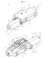
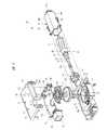
図2(a)、(b)はそれぞれ図1に示すサンルーフモータの詳細を示す斜視図であり、図3は図2に示すサンルーフモータの分解斜視図、図4はヨークとギヤケースとの固定部分を示す平面図である。 2A and 2B are perspective views showing details of the sunroof motor shown in FIG. 1, FIG. 3 is an exploded perspective view of the sunroof motor shown in FIG. 2, and FIG. 4 is a fixed portion between the yoke and the gear case. FIG.
図2(a)、(b)に示すように、このサンルーフモータ21はブラシ付きモータであるモータ本体23を備えている。このモータ本体23のヨーク24は、軸心を中心として湾曲する一対の円弧部24aとこれらの円弧部24aを連ねる互いに平行な一対の平板部24bとその軸方向の一端を閉塞する底部24cとを備えた断面略小判形の有底筒状に形成されており、図3に示すように、このヨーク24の内部にはアマチュア25が収容されている。このアマチュア25はアマチュア軸26を備えており、アマチュア軸26の一端がヨーク24の底部24cに設けられる軸受(不図示)に支持されることにより、アマチュア25はヨーク24の内部で回転自在となっている。アマチュア軸26にはアマチュアコア27が固定されており、このアマチュアコア27には複数のアマチュアコイル28が巻装されている。また、アマチュア軸26にはアマチュアコア27に隣接してコンミテータ29が固定されており、各アマチュアコイル28のコイル端はそれぞれコンミテータ29に接続されている。 As shown in FIGS. 2A and 2B, the
ヨーク24の開口端にはアマチュア25つまりアマチュアコイル28へ給電するためにブラシ装置31が装着されている。図4に示すように、このブラシ装置31はブラシホルダ32に一対のブラシ33a,33bが装着された構造となっており、これらのブラシ33a,33bはコンミテータ29の外周面に摺接し、当該ブラシ33a,33bとコンミテータ29とを介して所定のタイミングで転流された駆動電流がアマチュアコイル28に供給されるようになっている。 A
ヨーク24の開口端には一対のボルト34とナット35とによりギヤケース36が固定されている。このギヤケース36は樹脂材料によりバスタブ状に形成されており、モータ本体23のアマチュア軸26はヨーク24からこのギヤケース36の内部にまで突出して当該ギヤケース36に収容されている。なお、アマチュア軸26の先端部位及び中間部位は、ギヤケース36の内部に設けられる軸受(不図示)に支持されるようになっている。また、ギヤケース36には5箇所の爪係合によりカバー体37が取り付けられ、ギヤケース36の開口端はこのカバー体37により閉塞されるようになっている。 A
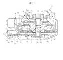
図5は図2(b)におけるA−A線に沿う断面図であり、図5に示すように、カバー体37により閉塞されるギヤケース36の内部には減速機構としてのウォームギヤ機構41が収容されている。ウォームギヤ機構41はウォーム41aとウォームホイル41bとを備えており、ウォーム41aはアマチュア軸26におけるギヤケース36の内部に突出した部分の外周面に一体に形成され、ウォームホイル41bは出力軸42に固定されて当該出力軸42とともにギヤケース36の内部に設けられた円筒状のギヤ収容部36aに回転自在に収容されている。ウォーム41aとウォームホイル41bは互いに噛み合わされており、これにより、アマチュア軸26の回転はウォームギヤ機構41を介して所定の回転数にまで減速されて出力軸42から出力される。 FIG. 5 is a sectional view taken along line AA in FIG. 2B. As shown in FIG. 5, a
なお、図示する場合には、ウォーム41aをアマチュア軸26の外周面に一体に形成するようにしているが、これに限らず、アマチュア軸26にウォーム41aを備えた軸を連結する構造にするなど、アマチュア軸26によりウォーム41aが回転駆動される構造であれば他の構造であってもよい。また、減速機構としてはウォームギヤ機構41に限らず、他の構造のものを用いるようにしてもよい。 In the illustrated case, the worm 41a is integrally formed on the outer peripheral surface of the
ギヤ収容部36aの開口端にはギヤカバー43が取り付けられており、当該ギヤカバー43によりギヤ収容部36aはギヤケース36内で隔離されている。これにより、ウォームギヤ機構41に塗布されたグリース等の潤滑油がギヤケース36のギヤ収容部36a以外の部分に漏れ出すことが防止される。 A
このサンルーフモータ21には、モータ本体23の作動を制御するために、制御基板51が設けられている。この制御基板51は基板51aにアマチュア25(アマチュアコイル28)へ供給する駆動電流を制御する制御回路51bが設けられた構造となっており、カバー体37と一体的に設けられた固定手段としての3箇所のクリップ52によりカバー体37の内面に固定されている。このクリップ52は、円柱状の本体52aとその上部に設けられたクリップ球52bとクリップ球52bから本体52aに至る十字のスリット52cとからなる公知の固定手段である。そして、カバー体37がギヤケース36に取り付けられることにより、制御基板51がギヤケース36の内部に一体的に設けられた制御基板収容部36b内に収容されるようになっている。 The
図3、図4に示すように、ブラシ装置31には一対の電源端子53,54が設けられ、制御基板51には一対の接続片55,56が設けられており、制御基板51が固定されたカバー体37をギヤケース36に取り付けると、これらの接続片55,56が対応する電源端子53,54に接続され、制御基板51(制御回路51b)と各ブラシ33a,33bとが電気的に接続されるようになっている。 As shown in FIGS. 3 and 4, the
また、ギヤケース36には一端がボルト34とナット35とを介してヨーク24に電気的に接続されるグランド端子(接地端子)57が設けられ、制御基板51にはグランド用の接続片58が設けられており、制御基板51が固定されたカバー体37をギヤケース36に取り付けると、この接続片58がグランド端子57に接続され、制御回路51bはヨーク24にグランド接続(接地)されるようになっている。 The
制御基板51の一端部には外部接続用のコネクタ59が設けられている。図2に示すように、このコネクタ59はギヤケース36から突出し、制御回路51bはこのコネクタ59を介して車両13に搭載されたバッテリ等の電源(不図示)や車室内に設けられたサンルーフスイッチ(不図示)に接続されるようになっている。そして、サンルーフスイッチが操作されると、コネクタ59を介して電源から制御回路51bに駆動電流が供給され、この駆動電流が制御回路51bにより所定の電流に制御されて、各接続片55,56と電源端子53,54およびブラシ33a,33bとコンミテータ29とを介してアマチュア25(アマチュアコイル28)に供給される。 A
なお、符号61はカバー体37に設けられた位置決め部であり、この位置決め部61が制御基板51に形成される位置決め孔62に軽圧入状に挿通され、且つ、ギヤケース36に設けられる位置決め突起63に係合することにより、制御基板51をギヤケース36の制御基板収容部36bの所定位置に位置決めすることができるようになっている。
アマチュア軸26の回転を検出するために、このサンルーフモータ21には回転センサが設けられている。この回転センサは、アマチュア軸26に固定されたセンサマグネット72を備えており、このセンサマグネット72は周方向に複数の磁極が並べて着磁された多極着磁磁石となっており、アマチュア軸26とともに回転してするようになっている。 In order to detect the rotation of the
一方、図3に示すように、制御基板51上には、それぞれセンサマグネット72に対向するように一対のホールIC73a,73bがアマチュア軸26の軸心に対して90度の角度となるように配され、センサマグネット72の出力する磁界の変化を90度の位相差を持って検出するように設けられている。各ホールIC73a,73bはセンサマグネット72の発生する磁界の変化を検出し、これをアマチュア軸26の回転数に反比例した周期のパルス信号として出力するようになっている。各ホールIC73a,73bの検出信号つまりパルス信号は制御回路51bに入力され、制御回路51bはこれらのホールIC73a,73bから入力されるパルス信号の周期や各ホールIC73a,73bから入力されるパルス信号の出現タイミング等に基づいてアマチュアコイル28へ供給する駆動電流の制御を実行するようになっている。 On the other hand, as shown in FIG. 3, a pair of
図5に示すように、出力軸42は、その軸方向をアマチュア軸26の軸方向に対して直交し、且つヨーク24の平板部24bに対しても直交する方向に向けて配置されており、その先端はギヤケース36の底面36cから当該ケース36の外部(図中上方向)に突出している。ギヤケース36の底面36c上つまり外面上には前述の駆動ギヤ22が配置されており、この駆動ギヤ22は出力軸42のギヤケース36の底面36cから突出した先端に固定され、当該出力軸42とともに回転するようになっている。 As shown in FIG. 5, the
図5に示すように、出力軸42の他端(図中下方向)には例えば六角レンチ等の工具が係合可能な工具孔42aが形成されており、モータ本体23が故障等した場合には、カバー体37に形成された貫通孔37aを介して工具孔42aに工具を係合させて、当該工具により出力軸42を回転駆動して、ルーフパネル12を手動で開閉操作することができるようになっている。 As shown in FIG. 5, a
図2(b)と図5に示すように、各駆動ケーブル17a,17bの駆動ギヤ22との係合つまり駆動ギヤ22との噛み合いを保持するために、ギヤケース36の底面36cには一対のケーブルガイド81,82が凸設されている。 As shown in FIGS. 2B and 5, a pair of cables is attached to the
図6は駆動ギヤと駆動ケーブルとの噛み合い部分の構造を示す平面図であり、これらのケーブルガイド81,82はそれぞれギヤケース36の底面36cから突出するブロック状に形成されており、当該ギヤケース36と一体に形成された樹脂製となっている。 FIG. 6 is a plan view showing the structure of the meshing portion between the drive gear and the drive cable. These cable guides 81 and 82 are each formed in a block shape protruding from the
一方のケーブルガイド81は出力軸42と平行な平面状に形成されたガイド面81aを備えている。このガイド面81aは所定の間隔を空けて駆動ギヤ22と対向しており、一方の駆動ケーブル17aはこのガイド面81aと駆動ギヤ22との間に配置されている。これにより、駆動ケーブル17aはガイド面81aにより駆動ギヤ22からその径方向に離れる方向への移動が規制され、当該駆動ギヤ22との噛み合いが保持されるようになっている。同様に、他方のケーブルガイド82はガイド面81aと平行な平面状に形成されたガイド面82aを備えている。このガイド面82aはガイド面81aとは反対側において駆動ギヤ22に所定の間隔を空けて対向しており、他方の駆動ケーブル17bはこのガイド面82aと駆動ギヤ22との間に配置されている。これにより、駆動ケーブル17bはガイド面82aにより駆動ギヤ22からその径方向に離れる方向への移動が規制され、当該駆動ギヤ22との噛み合いが保持されるようになっている。 One
樹脂製のガイド面81a,82aが駆動ケーブル17a,17bとの摺接により摩耗することを防止するために、ギヤケース36の底面36cには金属製のガイドプレート83が装着されている。 In order to prevent the resin guide surfaces 81a and 82a from being worn by sliding contact with the
図7は図6に示すガイドプレートの詳細を示す斜視図であり、このガイドプレート83は、それぞれ対応するケーブルガイド81,82に装着される摺接部としての一対のガイド壁部84a,84bと、これらのガイド壁部84a,84b同士を連結する連結部としての一対の連結橋部85a,85bとを備えており、これらが鋼板により一体に形成された構造となっている。 FIG. 7 is a perspective view showing details of the guide plate shown in FIG. 6, and this
一方のガイド壁部84aはケーブルガイド81のガイド面81aに平行な平板状に形成されており、これと一体に形成される一対の爪部86aがケーブルガイド81の天面部分に設けられた取付孔81bに挿入されることにより、ガイド面81aに平行に重ねられた状態となって当該ケーブルガイド81に装着されるようになっている。同様に、他方のガイド壁部84bはケーブルガイド82のガイド面82aに平行な平板状に形成されており、これと一体に形成される一対の爪部86bがケーブルガイド82の天面部分に設けられた取付孔82bに挿入されることにより、ガイド面82aに平行に重ねられた状態となって当該ケーブルガイド82に装着されるようになっている。各ガイド壁部84a,84bが対応するケーブルガイド81,82に装着されると、各駆動ケーブル17a,17bはガイドプレート83の対応するガイド壁部84a,84bに摺接して駆動ギヤ22との噛み合いが保持される。これにより、ケーブルガイド81,82のガイド面81a,82aに駆動ケーブル17a,17bを直接摺接させることをなくして、駆動ケーブル17a,17bとの摺接による各ガイド面81a,82aの摩耗を防止することができる。 One
なお、各ガイド壁部84a,84bの両側部にはガイド壁部84a,84bに対して駆動ケーブル17a,17bから離れる方向に傾斜する傾斜壁87a,87bが一体に設けられており、これらの傾斜壁87a,87bにより駆動ケーブル17a,17bが滑らかにガイド壁部84a,84bに案内されるようになっている。 In addition,
一方、一対の連結橋部85a,85bは駆動ケーブル17a,17bに直交する方向に延びる長尺の板状に形成されており、それぞれガイド壁部84a,84bの下端(ギヤケース36の側の端部)の幅方向(駆動ケーブル17a,17bの長手方向)の両端部において当該ガイド壁部84a,84bに連結されるとともに、ガイドプレート83がギヤケース36に装着されたときに、それぞれ出力軸42を挟んで当該出力軸42の両側に並べて配置されるようになっている。また、図6に示すように、各連結橋部85a,85bは、それぞれ長手方向の中間部分において互いが接近するように、出力軸42の軸方向からの平面視で、くの字に曲げて形成されており、当該長手方向中間部分はギヤケース36の底面36cと駆動ギヤ22の底面(ギヤケース36の底面36cと対向する面)との間に配置されている。 On the other hand, the pair of connecting
ところで、このサンルーフモータ21では、図5に示すように、出力軸42はこれに固定されるウォームホイル41bと駆動ギヤ22とがギヤケース36の内外面に配置されるとともに、ギヤケース36に対して回転自在の構成となっている。そのため、出力軸42は軸方向に若干の移動代つまりガタを有する構造となっており、モータ作動時に出力軸42とともに駆動ギヤ22やウォームホイル41bが軸方向に移動して、ギヤケース36との衝突音等の異音を生じるおそれがある。そこで、このサンルーフモータ21では、ガイドプレート83に設けられる連結橋部85a,85bを出力軸42の軸方向に弾性変形自在に形成し、つまり、連結橋部85a,85bにスプリング機能を持たせ、当該弾性力により駆動ギヤ22をギヤケース36に対して軸方向外側に付勢して出力軸42の軸方向へのガタを吸収するようにしている。 In the
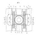
図8は図7に示す連結橋部による駆動ギヤの付勢構造を示す説明図であり、各連結橋部85a,85bは各ガイド壁部84a,84bの間における中間部分がギヤケース36の底面36cに対して駆動ギヤ22の側に向けた軸方向に突出するように湾曲して形成されており、当該湾曲度合いを増減させる方向つまり出力軸42の軸方向に弾性変形自在となっている。また、各連結橋部85a,85bは、その長手方向の両端部においてギヤケース36の底面36cに当該底面36cと平行且つ当該底面36cよりも一段下げて形成された支持面88に当接するとともに、その長手方向中間部分を支持面88の側に近づける方向つまり湾曲度合いを低減させる方向に弾性変形させた状態でギヤケース36の支持面88と駆動ギヤ22との間に配置されている。これにより、駆動ギヤ22は連結橋部85a,85bの弾性力により出力軸42の軸方向であってギヤケース36の支持面88(底面36c)から離れる方向に付勢され、出力軸42はウォームホイル41bがギヤケース36の内面に当接した状態となって、その軸方向のガタが吸収された状態とされる。 FIG. 8 is an explanatory view showing the drive gear urging structure by the connecting bridge portion shown in FIG. 7, and each connecting
このように、このサンルーフモータ21では、一対のガイド壁部84a,84bを互いに連結する連結橋部85a,85bを出力軸42の軸方向に弾性変形自在に形成し、この連結橋部85a,85bをギヤケース36と駆動ギヤ22との間に配置して、当該連結橋部85a,85bにより駆動ギヤ22を軸方向に付勢するようにしたので、出力軸42が軸方向にガタを有する構造であっても、駆動ギヤ22を軸方向に付勢して出力軸42のガタを吸収することができる。これにより、駆動ギヤ22やウォームホイル41bが出力軸42とともに軸方向に移動してギヤケース36に衝突することにより生じる衝突音を防止して、このサンルーフモータ21の作動時における異音の発生を防止することができる。 As described above, in the
また、このサンルーフモータ21では、出力軸42を軸方向に付勢するための弾性体等の部品をガイドプレート83とは別に設けることなく、一対のガイド壁部84a,84bを互いに連結する連結橋部85a,85bにより駆動ギヤ22を軸方向に付勢することができるので、このサンルーフモータ21の部品点数を低減して、そのコストを低減することができる。さらに、ギヤケース36にガイドプレート83を装着することで駆動ギヤ22を軸方向に付勢する構造を備えることになるので、出力軸42を軸方向に付勢するための弾性体等の部品をガイドプレート83とは別に組み付ける必要がなく、このサンルーフモータ21の組み付け作業を削減して、そのコストを低減することができる。 In the
さらに、このサンルーフモータ21では、ガイドプレート83に出力軸42を挟んで並ぶ一対の連結橋部85a,85bを設けるようにしたので、出力軸42を中心として均等に駆動ギヤ22を付勢することができる。これにより、駆動ギヤ22を確実に付勢して、出力軸42が軸方向にガタを有することにより生じるサンルーフモータ21の異音を確実に防止することができる。 Further, in the
本発明は前記実施の形態に限定されるものではなく、その要旨を逸脱しない範囲で種々変更可能であることはいうまでもない。例えば、前記実施の形態においては、本発明を車両13のサンルーフ装置11に用いられるサンルーフモータ21に適用しているが、これに限らず、一対の駆動ケーブル17a,17bを介して被駆動体を作動させる電動モータであれば、他の被駆動体を駆動する電動モータに本発明を適用するようにしてもよい。 It goes without saying that the present invention is not limited to the above-described embodiment, and various modifications can be made without departing from the scope of the invention. For example, in the above-described embodiment, the present invention is applied to the
また、前記実施の形態においては、ガイドプレート83に一対の連結橋部85a,85bを設けるようにしているが、これに限らず、その数は問わない。 Moreover, in the said embodiment, although a pair of connection bridge | bridging
11 サンルーフ装置
12 ルーフパネル(被駆動体)
13 車両
13a ルーフ
13b フロントガラス
14 開口部
15a,15b シュー
16 ガイドレール
17a,17b 駆動ケーブル
21 サンルーフモータ(電動モータ)
22 駆動ギヤ(出力部材)
23 モータ本体
24 ヨーク
24a 円弧部
24b 平板部
24c 底部
25 アマチュア
26 アマチュア軸
27 アマチュアコア
28 アマチュアコイル
29 コンミテータ
31 ブラシ装置
32 ブラシホルダ
33a,33b ブラシ
34 ボルト
35 ナット
36 ギヤケース
36a ギヤ収容部
36b 制御基板収容部
36c 底面
37 カバー体
37a 貫通孔
41 ウォームギヤ機構(減速機構)
41a ウォーム
41b ウォームホイル
42 出力軸
42a 工具孔
43 ギヤカバー
51 制御基板
51a 基板
51b 制御回路
52 クリップ
52a 本体
52b クリップ球
52c スリット
53,54 電源端子
55,56 接続片
57 グランド端子
58 接続片
59 コネクタ
61 位置決め部
62 位置決め孔
63 位置決め突起
72 センサマグネット
73a,73b ホールIC
81,82 ケーブルガイド
81a,82a ガイド面
81b,82b 取付孔
83 ガイドプレート
84a,84b ガイド壁部(摺接部)
85a,85b 連結橋部(連結部)
86a,86b 爪部
87a,87b 傾斜壁
88 支持面11
13
22 Drive gear (output member)
23
81, 82 Cable guides 81a, 82a Guide surfaces 81b, 82b Mounting holes 83
85a, 85b Connecting bridge part (connecting part)
86a,
Claims (2)
Translated fromJapanese有底筒状に形成されるヨークと、
前記ヨークの開口端に固定されるギヤケースと、
前記ギヤケース内に突出するアマチュア軸を備え、前記ヨークに回転自在に支持されるアマチュアと、
前記ギヤケースに収容され、前記アマチュア軸の回転を減速して出力軸から出力する減速機構と、
前記出力軸に固定されるとともに前記ギヤケースの外面上に配置され、一対の前記駆動ケーブルに係合する出力部材と、
それぞれ前記出力部材に対向して前記ギヤケースに設けられ、それぞれ対応する前記駆動ケーブルの前記出力部材との係合を保持する一対のケーブルガイドと、
それぞれ対応する前記ケーブルガイドに装着され前記駆動ケーブルに摺接する一対の摺接部と、それぞれ対応する前記ケーブルガイドの取付孔に挿入され一対の前記摺接部をそれぞれ対応する前記ケーブルガイドのガイド面に平行に重ねられた状態とする一対の爪部と、一対の前記摺接部を連結する連結部とを、鋼板により一体としたガイドプレートとを有し、
前記連結部は前記出力軸の軸方向に弾性変形自在に形成され、前記ギヤケースと前記出力部材との間に配置されて該出力部材を軸方向に付勢することを特徴とする電動モータ。An electric motor for operating the driven body by driving a pair of drive cables connected to the driven body in an axial direction,
A yoke formed into a bottomed cylindrical shape;
A gear case fixed to the open end of the yoke;
An amateur shaft that projects into the gear case and is rotatably supported by the yoke;
A speed reduction mechanism that is housed in the gear case and decelerates rotation of the armature shaft and outputs from the output shaft;
An output member that is fixed to the output shaft and disposed on an outer surface of the gear case, and engages a pair of the drive cables;
A pair of cable guides that are respectively provided in the gear case so as to face the output member and hold the engagement of the corresponding drive cables with the output member;
A pair of sliding contact portions that are mounted on the corresponding cable guides and are in sliding contact with the drive cable, anda guide surface of the cable guide that is inserted into the corresponding mounting hole of the cable guide andthat corresponds to the pair of sliding contact portions. A pair of claw portions that are overlapped in parallel with each other, and a guide plate thatintegrates a connecting portion that connects the pair of sliding contact portions witha steel plate,
The electric motor is characterized in that the connecting portion is formed to be elastically deformable in the axial direction of the output shaft, and is arranged between the gear case and the output member to urge the output member in the axial direction.
The electric motor according to claim 1, wherein the guide plate includes a pair of the connecting portions arranged with the output shaft interposed therebetween.
Priority Applications (1)
| Application Number | Priority Date | Filing Date | Title |
|---|---|---|---|
| JP2008220633AJP5216487B2 (en) | 2008-08-29 | 2008-08-29 | Electric motor |
Applications Claiming Priority (1)
| Application Number | Priority Date | Filing Date | Title |
|---|---|---|---|
| JP2008220633AJP5216487B2 (en) | 2008-08-29 | 2008-08-29 | Electric motor |
Publications (2)
| Publication Number | Publication Date |
|---|---|
| JP2010057295A JP2010057295A (en) | 2010-03-11 |
| JP5216487B2true JP5216487B2 (en) | 2013-06-19 |
Family
ID=42072630
Family Applications (1)
| Application Number | Title | Priority Date | Filing Date |
|---|---|---|---|
| JP2008220633AActiveJP5216487B2 (en) | 2008-08-29 | 2008-08-29 | Electric motor |
Country Status (1)
| Country | Link |
|---|---|
| JP (1) | JP5216487B2 (en) |
Families Citing this family (1)
| Publication number | Priority date | Publication date | Assignee | Title |
|---|---|---|---|---|
| JP5941326B2 (en)* | 2012-04-03 | 2016-06-29 | 株式会社ミツバ | Drive device |
Family Cites Families (1)
| Publication number | Priority date | Publication date | Assignee | Title |
|---|---|---|---|---|
| JP5039364B2 (en)* | 2006-11-17 | 2012-10-03 | ベバスト ジャパン株式会社 | Drive device |
- 2008
- 2008-08-29JPJP2008220633Apatent/JP5216487B2/enactiveActive
Also Published As
| Publication number | Publication date |
|---|---|
| JP2010057295A (en) | 2010-03-11 |
Similar Documents
| Publication | Publication Date | Title |
|---|---|---|
| JP5213590B2 (en) | Electric motor | |
| JP5139205B2 (en) | Electric motor | |
| JP2009201277A (en) | Electric motor with speed reduction mechanism | |
| JP2008184880A (en) | Automatic opening/closing device of vehicle | |
| JP5139206B2 (en) | Electric motor | |
| JP5216487B2 (en) | Electric motor | |
| JP5097649B2 (en) | Electric motor and sunroof motor | |
| CN111422243B (en) | Sensor for detecting a position of a body | |
| JP4827492B2 (en) | Electric motor | |
| JP2009195027A (en) | Bearing fixing method to rotating shaft, rotating shaft assembly, and electric motor with speed reduction mechanism | |
| US9847699B2 (en) | Electric motor | |
| JP2008141917A (en) | Motor | |
| JP4861769B2 (en) | Electric motor with reduction mechanism | |
| JP2005224077A (en) | Motor-driving device | |
| CN215803900U (en) | Actuator device | |
| JP5164747B2 (en) | Electric motor | |
| US20070159013A1 (en) | Motor drive device | |
| JP3715896B2 (en) | motor | |
| JP5075766B2 (en) | Electric motor | |
| JP2008184879A (en) | Automatic switchgear for vehicles | |
| JP2009293643A (en) | Electric motor with speed reduction mechanism | |
| JP2009296698A (en) | Electric motor with reduction gear mechanism | |
| JP2008184877A (en) | Automatic switchgear for vehicles | |
| JP6487857B2 (en) | Electric steering lock device | |
| JP2019106889A (en) | Motor device |
Legal Events
| Date | Code | Title | Description |
|---|---|---|---|
| A621 | Written request for application examination | Free format text:JAPANESE INTERMEDIATE CODE: A621 Effective date:20110210 | |
| A131 | Notification of reasons for refusal | Free format text:JAPANESE INTERMEDIATE CODE: A131 Effective date:20120710 | |
| A977 | Report on retrieval | Free format text:JAPANESE INTERMEDIATE CODE: A971007 Effective date:20120711 | |
| A521 | Written amendment | Free format text:JAPANESE INTERMEDIATE CODE: A523 Effective date:20120905 | |
| TRDD | Decision of grant or rejection written | ||
| A01 | Written decision to grant a patent or to grant a registration (utility model) | Free format text:JAPANESE INTERMEDIATE CODE: A01 Effective date:20130226 | |
| A61 | First payment of annual fees (during grant procedure) | Free format text:JAPANESE INTERMEDIATE CODE: A61 Effective date:20130304 | |
| R150 | Certificate of patent or registration of utility model | Ref document number:5216487 Country of ref document:JP Free format text:JAPANESE INTERMEDIATE CODE: R150 Free format text:JAPANESE INTERMEDIATE CODE: R150 | |
| FPAY | Renewal fee payment (event date is renewal date of database) | Free format text:PAYMENT UNTIL: 20160308 Year of fee payment:3 |