JP5214617B2 - Tube connector - Google Patents
Tube connectorDownload PDFInfo
- Publication number
- JP5214617B2 JP5214617B2JP2009532402AJP2009532402AJP5214617B2JP 5214617 B2JP5214617 B2JP 5214617B2JP 2009532402 AJP2009532402 AJP 2009532402AJP 2009532402 AJP2009532402 AJP 2009532402AJP 5214617 B2JP5214617 B2JP 5214617B2
- Authority
- JP
- Japan
- Prior art keywords
- plug
- latch element
- receptacle
- tube connector
- bore
- Prior art date
- Legal status (The legal status is an assumption and is not a legal conclusion. Google has not performed a legal analysis and makes no representation as to the accuracy of the status listed.)
- Expired - Fee Related
Links
- 210000000481breastAnatomy0.000description23
- 238000000034methodMethods0.000description6
- 239000012530fluidSubstances0.000description4
- 230000000712assemblyEffects0.000description3
- 238000000429assemblyMethods0.000description3
- 239000008267milkSubstances0.000description3
- 210000004080milkAnatomy0.000description3
- 235000013336milkNutrition0.000description3
- 239000012858resilient materialSubstances0.000description3
- 230000008901benefitEffects0.000description2
- 210000002445nippleAnatomy0.000description2
- 230000009471actionEffects0.000description1
- 230000006870functionEffects0.000description1
- 238000004519manufacturing processMethods0.000description1
- 239000000463materialSubstances0.000description1
- 230000004048modificationEffects0.000description1
- 238000012986modificationMethods0.000description1
- 238000007789sealingMethods0.000description1
- 230000009466transformationEffects0.000description1
Images


Classifications
- A—HUMAN NECESSITIES
- A61—MEDICAL OR VETERINARY SCIENCE; HYGIENE
- A61M—DEVICES FOR INTRODUCING MEDIA INTO, OR ONTO, THE BODY; DEVICES FOR TRANSDUCING BODY MEDIA OR FOR TAKING MEDIA FROM THE BODY; DEVICES FOR PRODUCING OR ENDING SLEEP OR STUPOR
- A61M39/00—Tubes, tube connectors, tube couplings, valves, access sites or the like, specially adapted for medical use
- A61M39/10—Tube connectors; Tube couplings
- A61M39/1055—Rotating or swivel joints
- A—HUMAN NECESSITIES
- A61—MEDICAL OR VETERINARY SCIENCE; HYGIENE
- A61M—DEVICES FOR INTRODUCING MEDIA INTO, OR ONTO, THE BODY; DEVICES FOR TRANSDUCING BODY MEDIA OR FOR TAKING MEDIA FROM THE BODY; DEVICES FOR PRODUCING OR ENDING SLEEP OR STUPOR
- A61M1/00—Suction or pumping devices for medical purposes; Devices for carrying-off, for treatment of, or for carrying-over, body-liquids; Drainage systems
- A61M1/84—Drainage tubes; Aspiration tips
- A—HUMAN NECESSITIES
- A61—MEDICAL OR VETERINARY SCIENCE; HYGIENE
- A61M—DEVICES FOR INTRODUCING MEDIA INTO, OR ONTO, THE BODY; DEVICES FOR TRANSDUCING BODY MEDIA OR FOR TAKING MEDIA FROM THE BODY; DEVICES FOR PRODUCING OR ENDING SLEEP OR STUPOR
- A61M39/00—Tubes, tube connectors, tube couplings, valves, access sites or the like, specially adapted for medical use
- A61M39/10—Tube connectors; Tube couplings
- A61M39/12—Tube connectors; Tube couplings for joining a flexible tube to a rigid attachment
- F—MECHANICAL ENGINEERING; LIGHTING; HEATING; WEAPONS; BLASTING
- F16—ENGINEERING ELEMENTS AND UNITS; GENERAL MEASURES FOR PRODUCING AND MAINTAINING EFFECTIVE FUNCTIONING OF MACHINES OR INSTALLATIONS; THERMAL INSULATION IN GENERAL
- F16L—PIPES; JOINTS OR FITTINGS FOR PIPES; SUPPORTS FOR PIPES, CABLES OR PROTECTIVE TUBING; MEANS FOR THERMAL INSULATION IN GENERAL
- F16L37/00—Couplings of the quick-acting type
- F16L37/08—Couplings of the quick-acting type in which the connection between abutting or axially overlapping ends is maintained by locking members
- F16L37/084—Couplings of the quick-acting type in which the connection between abutting or axially overlapping ends is maintained by locking members combined with automatic locking
- F16L37/098—Couplings of the quick-acting type in which the connection between abutting or axially overlapping ends is maintained by locking members combined with automatic locking by means of flexible hooks
- F16L37/0985—Couplings of the quick-acting type in which the connection between abutting or axially overlapping ends is maintained by locking members combined with automatic locking by means of flexible hooks the flexible hook extending radially inwardly from an outer part and engaging a bead, recess or the like on an inner part
- A—HUMAN NECESSITIES
- A61—MEDICAL OR VETERINARY SCIENCE; HYGIENE
- A61M—DEVICES FOR INTRODUCING MEDIA INTO, OR ONTO, THE BODY; DEVICES FOR TRANSDUCING BODY MEDIA OR FOR TAKING MEDIA FROM THE BODY; DEVICES FOR PRODUCING OR ENDING SLEEP OR STUPOR
- A61M1/00—Suction or pumping devices for medical purposes; Devices for carrying-off, for treatment of, or for carrying-over, body-liquids; Drainage systems
- A61M1/06—Milking pumps
- A61M1/062—Pump accessories
- A—HUMAN NECESSITIES
- A61—MEDICAL OR VETERINARY SCIENCE; HYGIENE
- A61M—DEVICES FOR INTRODUCING MEDIA INTO, OR ONTO, THE BODY; DEVICES FOR TRANSDUCING BODY MEDIA OR FOR TAKING MEDIA FROM THE BODY; DEVICES FOR PRODUCING OR ENDING SLEEP OR STUPOR
- A61M39/00—Tubes, tube connectors, tube couplings, valves, access sites or the like, specially adapted for medical use
- A61M39/10—Tube connectors; Tube couplings
- A61M2039/1027—Quick-acting type connectors
- A—HUMAN NECESSITIES
- A61—MEDICAL OR VETERINARY SCIENCE; HYGIENE
- A61M—DEVICES FOR INTRODUCING MEDIA INTO, OR ONTO, THE BODY; DEVICES FOR TRANSDUCING BODY MEDIA OR FOR TAKING MEDIA FROM THE BODY; DEVICES FOR PRODUCING OR ENDING SLEEP OR STUPOR
- A61M39/00—Tubes, tube connectors, tube couplings, valves, access sites or the like, specially adapted for medical use
- A61M39/10—Tube connectors; Tube couplings
- A61M2039/1044—Verifying the connection, e.g. audible feedback, tactile feedback, visual feedback, using external light sources
Landscapes
- Health & Medical Sciences (AREA)
- Heart & Thoracic Surgery (AREA)
- Engineering & Computer Science (AREA)
- Animal Behavior & Ethology (AREA)
- Public Health (AREA)
- Biomedical Technology (AREA)
- Hematology (AREA)
- Life Sciences & Earth Sciences (AREA)
- Veterinary Medicine (AREA)
- General Health & Medical Sciences (AREA)
- Anesthesiology (AREA)
- Pulmonology (AREA)
- Surgery (AREA)
- Vascular Medicine (AREA)
- General Engineering & Computer Science (AREA)
- Mechanical Engineering (AREA)
- External Artificial Organs (AREA)
- Infusion, Injection, And Reservoir Apparatuses (AREA)
- Quick-Acting Or Multi-Walled Pipe Joints (AREA)
Description
Translated fromJapanese本発明は、一般的にチューブコネクタに関し、より具体的には、一側面においてエアチューブ用の改良コネクタを含む搾乳器組立体に関する。 The present invention relates generally to tube connectors, and more specifically to a breast pump assembly including an improved connector for an air tube in one aspect.
搾乳器がよく知られており、一般的に、乳房にフィットするフード又はシールドと、ブレストシールド内に、間欠的な真空(又は負圧)を発生させるためのフードに連結された真空ポンプと、絞り出されたミルク用の容器とを含む。負圧は、大気圧よりも低い圧力であり、搾乳器には、時には、正圧も使用される。典型的には、真空ポンプの間欠的な吸引作用は、乳房及び乳頭を引っ張るのに役立ち、これにより、ミルクを絞り出す。ミルクは、フードから、導管構造を通じて、保管及び後での使用のために哺乳瓶のような収集容器の中に流れる。 Milking machines are well known, generally a hood or shield that fits the breast, and a vacuum pump connected to the hood for generating an intermittent vacuum (or negative pressure) within the breast shield; A squeezed milk container. Negative pressure is lower than atmospheric pressure, and positive pressure is sometimes used for breast pumps. Typically, the intermittent suction action of the vacuum pump helps to pull the breast and nipple, thereby squeezing out the milk. Milk flows from the hood through the conduit structure into a collection container such as a baby bottle for storage and later use.
搾乳器は、手動又は電動で作動することができる。手動搾乳器組立体では、間欠的な真空は、典型的には、搾乳器組立体に直接取り付けられるピストンタイプ又は他の手動ポンプによって発生させられる。モータドライブの搾乳器組立体での間欠的な圧力(例えば真空)は、典型的には、ブレストシールド及び搾乳器組立体とは別体のモータドライブユニットから得られる。そして真空は、プラスチックチューブを通して搾乳器組立体に伝達される。プラスチックチューブは、しばしば、コネクタの使用によって、モータドライブのポンプ及び/又は搾乳器組立体の一つ又は両方に取り付けられる。 The breast pump can be operated manually or electrically. In manual breast pump assemblies, intermittent vacuum is typically generated by a piston type or other manual pump that is directly attached to the breast pump assembly. Intermittent pressure (e.g., vacuum) at the motor drive breast pump assembly is typically obtained from a motor drive unit separate from the breast shield and breast pump assembly. The vacuum is then transmitted to the breast pump assembly through the plastic tube. The plastic tube is often attached to one or both of the motor drive pump and / or breast pump assembly by use of a connector.
搾乳器組立体全体にわたる空気の移動のために、コネクタは、気密シールを提供する。その上、繰り返し構成部品をつないだり、外したりするために、ユーザが、コネクタを容易に操作できる必要がある。従来技術のコネクタは、連結及びシールをもたらす、突出するステムに挿入された生チューブ、又はテーパーを有する円筒状の一対の雄表面及び雌表面を使用していた。これらの方法は、現実的には、連結がなされたことの「積極的なフィードバック」をユーザに与えず、さらに、ときには、連結したり、外したりするために顕著な努力を要求する。これらの従来技術のコネクタの他の問題点は、ユーザがポンプ作動中の移動によりチューブを引っ張る場合に、連結箇所でチューブの曲がり及びキンクが起こることである。 For air movement throughout the breast pump assembly, the connector provides a hermetic seal. In addition, the user needs to be able to easily operate the connector in order to repeatedly connect and disconnect components. Prior art connectors have used a raw tube inserted into a protruding stem or a pair of cylindrical male and female surfaces with a taper that provides connection and sealing. These methods practically do not give the user “positive feedback” of the connection being made, and sometimes require significant effort to connect and disconnect. Another problem with these prior art connectors is that when the user pulls the tube due to movement during pump operation, the tube will bend and kink at the connection point.
従って、連結がなされたことを、ユーザに積極的にフィードバックし、連結を容易にし、且つチューブのキンクをより良く回避することができるコネクタの要求がある。本発明は、この要求を満たす。 Therefore, there is a need for a connector that can positively feed back to the user that the connection has been made, facilitate the connection, and better avoid tube kinking. The present invention satisfies this need.
本発明の目的は、堅牢な連結がなされたことの積極的なフィードバックをユーザに与えるチューブコネクタを提供することである。 It is an object of the present invention to provide a tube connector that provides the user with positive feedback that a robust connection has been made.
本発明の他の目的は、顕著な努力なしに、連結したり、外したりすることができる、例えば2つのチューブ状物体を連結するためのチューブコネクタを提供することである。 Another object of the present invention is to provide a tube connector for connecting two tubular objects, for example, which can be connected and disconnected without significant effort.
さらに、本発明の他の目的は、キンクを回避するために連結部の回転を可能にするチューブコネクタを提供することである。 Furthermore, it is another object of the present invention to provide a tube connector that allows rotation of the connecting portion to avoid kinking.
本発明の一実施形態は、ポート(又はソケット若しくはウェル)に嵌るチューブ端のような2つのチューブ状物体を連結するためのチューブコネクタを提供する。チューブコネクタは、(チューブの端にある)プラグ部材を受け入れるように寸法決めされ、且つ形作られた栓受(ポート、ソケット、又はウェル)を有する。栓受は、内面に環状溝を有する。プラグ部材は、一形態では、栓受内に嵌るスリーブであるラッチ要素によって栓受内に固定され、ラッチ要素は、ラッチ要素と栓受を接合するために、栓受の環状溝に受け入れられる部分を有し、且つプラグ部材が、栓受内のラッチ要素内に押し込まれたときに、プラグ部材に嵌る。ラッチ要素は、栓受内部に延びる少なくとも一つの弾性リブを有する。プラグ部材は、内部に環状溝を有し、環状溝は、プラグ部材をラッチ要素内に、回転可能な方法で固定するために、ラッチ要素のリブと係合する。 One embodiment of the present invention provides a tube connector for connecting two tubular objects, such as a tube end that fits into a port (or socket or well). The tube connector has a plug receptacle (port, socket or well) sized and shaped to receive a plug member (at the end of the tube). The stopper has an annular groove on the inner surface. The plug member, in one form, is secured within the plug receptacle by a latching element, which is a sleeve that fits within the receptacle, and the latching element is a portion that is received in the annular groove of the receptacle to join the latching element and the receptacle. And the plug member fits into the plug member when pushed into the latch element in the plug receptacle. The latch element has at least one elastic rib extending into the stopper receptacle. The plug member has an annular groove therein that engages the ribs of the latch element to secure the plug member within the latch element in a rotatable manner.
上述の実施形態では、ラッチ要素は、最初は栓受とは別体であり、まず、プラグ上に配置され、次いで栓受内に受け入れられ、これにより「レトロフィット」構造を提供する。変形として、ユーザがプラグを挿入すれば足りるように、ラッチ要素を栓受と一体に作ってもよいし、又は予め栓受に組み付けてもよい。 In the embodiment described above, the latch element is initially separate from the plug receptacle and is first placed on the plug and then received within the receptacle, thereby providing a “retrofit” structure. As a variant, the latching element may be made integral with the plug receptacle or it may be pre-assembled to the receptacle so that it is sufficient for the user to insert the plug.
他の実施形態では、プラグの外面に、栓受の内面にある環状溝、又は栓受内に固定されたラッチ要素にある環状溝に係合する円周隆起部があるように、相互係合部材を逆にする。 In other embodiments, the outer surface of the plug is interengaged such that there is a circumferential ridge that engages an annular groove in the inner surface of the plug receptacle or an annular groove in a latch element secured within the receptacle. Reverse the member.
本発明の他の目的は、例えば、特定のタイプの搾乳器が特定の圧力源に連結されるように、或る構成要素だけをより確実に連結することができるようにする。搾乳器組立体は、多くの形状及び大きさで売っている。これらのポンプ組立体内の容積量は、「デッド」容積、即ち、真空源によって最初に移動させなければならない空気の限りにおいて、大きく変わることがある。大抵の場合、両者が特に一緒に使用するために設計されるので、与えられた圧力源について適当な搾乳器組立体を使用することの懸念があり、それほど適合していない或る他の搾乳器組立体は、望ましくない問題を生じさせることがある。 Another object of the present invention is to allow only certain components to be more reliably connected, for example so that a particular type of breast pump is connected to a particular pressure source. Milking machine assemblies sell in many shapes and sizes. The volume of these pump assemblies can vary greatly as long as the “dead” volume, ie, the air that must first be moved by the vacuum source. In most cases, both are specifically designed for use together, so there is a concern about using a suitable breast pump assembly for a given pressure source, and some other breast pumps that are not well suited The assembly can cause undesirable problems.
これらの目的を、他の目的及び利点と共に、全体を通して同様の参照番号が同様の部分を示す、本願の一部をなす添付図面を参照して、以下で完全に説明する発明の構造、及び操作からさらに理解できる。 These objects, together with other objects and advantages, structure and operation of the invention, which will be fully described below with reference to the accompanying drawings, which form a part hereof, wherein like reference numerals designate like parts throughout. Can be further understood.
ここに本発明のチューブコネクタを搾乳器組立体用に説明するが、本発明を、このタイプのコネクタから利益を得るかもしれないどんなデバイスにも使用できると考えられる。 Although the tube connector of the present invention is described herein for a breast pump assembly, it is contemplated that the present invention can be used with any device that may benefit from this type of connector.
図1は、本発明によるチューブコネクタ100の分解図である。チューブコネクタ100は、栓受102と、シールリング104と、ラッチ要素106と、プラグ部材108とを含む。図2に示すように、栓受102は、外面110と、第1の内面112及び第2の内面114とを有し、第1の内面112及び第2の内面114は、ボア116を画成する。 FIG. 1 is an exploded view of a
栓受102は、示されるような別体である必要はなく、より典型的には、プラグ108が連結することになるものと一体に作られることが理解され、且つ分かるであろう。従って、栓受102は、例えば以下に示すようにモータドライブに組み付けられた部品であってもよく、又はモータドライブと一体に形成されてもよい。従って、「栓受」を用いて、一般的にウェル、ソケット、オリフィス等と称する。 It will be appreciated and understood that the
図2を参照すると、軸線Aが、ボア116の中へ延びる。ボア116は、第1の内面112によって画成された第1の部分118と、第2の内面114によって画成された第2の部分120とを有する。第1の部分118は、第1の直径D1を有し、第2の部分120は、第2の直径D2を有する。第1の内面112は、円周溝又はチャンネル122をさらに含む。栓受102は、2つの端119,121を含む。栓受102の第1の端119は、図6−8に示すように、例えば、搾乳器組立体のモータドライブユニットに連結されるように、又はこれと一体に形成されるようになっている。栓受102の第2の端121は、以下でより詳細に説明するように、栓受内に、チューブコネクタの他の構成部品を受け入れる。 With reference to FIG. 2, the axis A extends into the
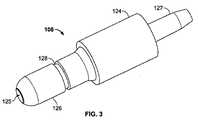
図3に示すように、プラグ部材108は、ベース124と、ステム126とを有する。ベース124は、ニップル127を介してチューブ(図示せず)に取り付けられるようになっている。ステム126は、ベース124の反対側の端から軸線方向に延びる。通路125が、流体/空気を搬送するために、ベース124とステム126の間で、プラグ部材108を貫いて延びる。ステム126は、円周溝又はチャンネル128を有し、ラッチ要素106(図4参照)内に受け入れられるようになっている。ラッチ要素は、好ましくは、チューブコネクタの部品を固定するための撓みを可能にし、且つこれらの間にシールを提供する弾性材料で形成される。 As shown in FIG. 3, the
図4のラッチ要素106は、その中にプラグ部材108のステム126を受け入れるように寸法決めされ、且つ形作られたスリーブの形態であり、栓受102のボア116の第1の部分118の中に受け入れられる。ラッチ要素106は、内面109と外面107を含み、外面107は、円周隆起部132を有し、ここでは、1つの隆起部132は、円周の周りに完全に周回しない。ラッチ要素106は、互いに、直径方向に間隔を隔てた2つの弾性タブ134をさらに含むが、どんな数のタブも考えられている。タブ134は、一端113がヒンジ状形態でラッチ要素106に連結(例えば、一体に)される。弾性タブ134の各々の自由端111は、内面109を越え、且つ僅かにラッチ要素106の内部内に延びるリブ136(図5)を有する。部分リングである隆起部132は、ラッチ要素106を、栓受102のボア116の中を第1の部分118に挿入したときに、栓受102の第1の内面112の溝122に係合する。リブ136は、プラグ部材108をラッチ要素106に挿入するときに、プラグ部材108のステム126の半径方向チャンネル128に弾性係合するように配置される。The
栓受102、シールリング104、ラッチ要素106、及びプラグ部材108の組立の一つの方法を図5に示す。シールリング104を、栓受102のボア116の第1の部分118に軸方向に挿入する。シールリング104は、シールリング104がボア116の第2の部分120に当接するように、ボア116の第1の部分118内に嵌り、且つボア116の第2の部分120のD2よりも大きい外径D1を有する。次いで、ラッチ要素106をボア116の第1の部分118に挿入し、当接するシールリング104が、気密シールを形成し、円周隆起部132が、栓受102の第1の内面112の溝122に係合する。ラッチ要素106は、ラッチ要素106が栓受102内で軸線方向に動かないような方法で栓受102内に固定されるが、ラッチ要素106と栓受102が回転可能な係合を有しもよいことも考えられる。プラグ部材108のステム126をラッチ要素106内に挿入する。タブ134のリブ136は、ステム126の半径方向チャンネル128に弾性的に係合し、プラグ部材108をラッチ要素106内、かくして栓受102に固定する。リブ136と半径方向チャンネル128との係合は、プラグ部材108が、ラッチ要素106内で、実質的に自由に回転できるようにする。ラッチ要素は、好ましくはプラスチック材料で形成される。 One method of assembling the
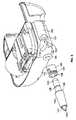
図6−8に示すように、栓受102は、搾乳器組立体のモータドライブユニットと一体に形成される。この実施形態でのチューブコネクタ100の組み立ては、上述したものと同様である。シールリング104を、シールリングがボア116の第2の部分120に当接するように、栓受102のボア116の第1の部分118に挿入する。ラッチ要素106を、先に説明したように挿入するとともに、円周隆起部132を溝122と係合させ、ラッチ要素106を栓受102内に固定する。次いでプラグ部材108をラッチ要素106内に取り外し可能に挿入し、タブ134をステム126の半径方向チャンネル128に弾性的に係合させ、プラグ部材108をラッチ要素106内に、かくして栓受102内に固定する。 As shown in FIGS. 6-8, the
図9は、本発明による、チューブコネクタ200の第2の実施形態の分解図である。第2の実施形態のチューブコネクタ200は、栓受202と、ラッチ要素206と、プラグ部材208を含む。 FIG. 9 is an exploded view of a second embodiment of a
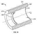
図10に示すように、この栓受202は、外面210と、内面212とを有し、内面212は、栓受216を貫くボア216を画成する。ボア216の中へ延びる軸線Bが画成される。内面212は、全周の周りにリング又は突起222を有する。栓受202は、2つの端219,221を含む。栓受202の第1の端219は、例えば、搾乳器組立体のモータドライブユニットに連結され、又はこれと一体に形成される。栓受202の第2の端221は、後に詳細に説明するように、その中にチューブコネクタ200の他の要素を受け入れる。 As shown in FIG. 10, the
図10に示すように、プラグ部材208は、その一端224がチューブ(図示せず)に取り付けられるようになっている。次いで、チューブは、プラグ部材208と一体に形成されてもよいし、さもなければ通路225に連結されてもよい。ずんぐりしたステム226が、ベース224とは反対側の端から軸線方向に延びる。通路225が、流体/空気を搬送するために、端224とステムの端226の間で、プラグ部材208を貫いて延びる。ステム226は、円周溝又はチャンネル128を有し、ラッチ要素206内に受け入れられるようになっている。 As shown in FIG. 10, the
図11を参照すると、このラッチ要素206も同様に、その中にプラグ部材208のステム226を受け入れるように寸法決めされ、且つ形作られたスリーブの形態であり、このタイプの栓受202のボア216の中に受け入れられる。変形のラッチ要素206は、内面209と外面207とを含む。外面207は、ラッチ要素206を栓受202のボア216に挿入したときに、栓受202の内面212のリング222(図12)と係合する、円周溝又はチャンネル232を有する。ラッチ要素206は、内面209にリブ又は隆起部234をさらに含み、隆起部234は、栓受208のステム226の円周溝228に合うように寸法決めされ、且つ形作られており、プラグ部材208をラッチ要素206に挿入したときに、リブ234が円周溝228に係合し、プラグ部材208をラッチ要素206内に固定する。 Referring to FIG. 11, the
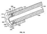
これは、図14に示されており、ラッチ要素206をボア216の中へ軸線方向に挿入し、溝232が栓受202の内面212の突起222と係合し、これにより、ラッチ要素206を栓受202内に固定する。プラグ部材208のステム226をラッチ要素206の中へ挿入し、リブ234がステム226の円周溝228と係合し、プラグ部材208をラッチ要素206内、かくして栓受202内に固定する。リブ234と円周溝228との係合は、プラグ部材208がラッチ要素206内で自由に回転できるようにする。ラッチ要素は、好ましくは、チューブ用コネクトの部品を固定するための撓みを可能にし、且つこれらの間にシールを提供する弾性材料で形成される。 This is illustrated in FIG. 14 where the
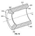
図15は、本発明によるチューブコネクタ300の第3の実施形態の分解図である。第3の実施形態のチューブコネクタ300は、栓受302と、ラッチ要素306と、プラグ部材308を含む。図16に示すように、栓受302は、外面310と、内面312を有し、内面312が、栓受302の中を通るボア316を画成する。ボア316の中へ延びる軸線Cが画成される。内面312は、全周にリング又は突起322を有する。栓受302は、2つの端319,321を含む。栓受302の第1の端319は、例えば、搾乳器組立体のモータドライブユニットに連結され、又はこれと一体に形成される。栓受302の第2の端321は、後に詳細に説明するように、その中にチューブコネクタ300の他の要素を受け入れる。 FIG. 15 is an exploded view of a third embodiment of a
図17に目を向けると、ラッチ要素306は、内面309と、外側に設けられた円周溝又はチャンネル332とを含む。溝332は、形状が環状であり、上に横たわるリップ333の下に位置する。ラッチ要素306は、内側309に、プラグ部材308のステム326の円周溝328に合うように形作られた肩部334を含み、プラグ部材308をラッチ要素306に挿入したときに、肩部334が円周溝328に係合し、プラグ部材308をラッチ要素306内に固定する。 Turning to FIG. 17, the latching
図18にさらに示すように、プラグ部材308は、任意の数の周知の方法で、チューブ(図示せず)に取り付けられるようになった端324を有する。ステム326(図15)が、プラグ部材308とは反対側の端から軸線方向に延びる。通路325が、流体/空気を搬送するために、ベース324とステム326の間で、プラグ部材308を貫いて延びる。 As further shown in FIG. 18, the
ラッチ要素306は、その中にプラグ部材308のステム326を受け入れるように、且つ栓受302のボア316に受け入れられるように寸法決めされ、且つ形作られる。ラッチ要素306を栓受302のボア316に挿入したときに、ラッチ要素306の溝332は、栓受302の内面312に沿ってリップ322と係合すると共に、それによりリップ333が、リップ322と栓受302の隣接した側壁との間に形成されたチャンネル335内の適所にスナップ嵌めされる。これは、栓受302とラッチ要素306の間のスナップ嵌めであり、かくしてこれらの要素は、係合するように寸法決めされる。 The
組み立ての一方法では、ラッチ要素306を、ボア316の中に軸方向に挿入し、溝332が、栓受302の内面312のリップ332に係合し、ラッチ要素306を栓受302内に固定する。プラグ部材308のステム326を組み合わせたラッチ要素306と栓受302の中に挿入し、肩部334が、ステム326円周溝328と係合し、かくしてプラグ部材308を、ラッチ要素306内、及び栓受302内に固定する。肩部334と円周溝328との間の係合は、プラグ部材308が、ラッチ要素306内で、実質的に自由に回転できるようにする。ラッチ要素は、好ましくは、チューブコネクタの部品を固定するための撓みを可能にし、且つこれらの間にシールを提供する弾性材料で形成される。 In one method of assembly, the
本発明の他の実施形態を図19−20に示す。図19に示すように、栓受402は、外面410と、内面412とを有する。内面412は、栓受402の中を通るボア416を画成する。ボア416の中に延びる軸線Dが画成される。円周溝422が、内面412の周りに形成される。栓受402は、2つの端419,421を含む。栓受402の第1の端419は、例えば搾乳器組立体のモータドライブユニットに連結されるように、又はこれと一体に形成されるようになっている。栓受402の第2の端421は、以下でより詳細に説明するように、その中に、チューブコネクタの他の構成部品を受け入れる。 Another embodiment of the invention is shown in FIGS. 19-20. As shown in FIG. 19, the
プラグ部材408は、端424とステム426とを有する。端424は、多くの周知の方法の何れかにより、チューブ(図示せず)に取り付けられるようになっている。ステム426が、ベース424とは反対側の端から軸線方向に延びる。通路425が、流体/空気を搬送するために、端424とステム426の間で、プラグ部材408の中を通って延びる。
図20にさらに示すように、シール部材404が、栓受402の内面412の円周溝422に嵌るように寸法決めされる。このシール部材404は、プラグ部材408を栓受402のボア416に挿入したときに、プラグ部材408の円周溝428と係合し、これによって、取り外す力に抵抗することによって、プラグ部材408を栓受402内に維持する気密シールを形成し、且つプラグ部材408を栓受402内で自由に回転させる。当然のことながら、先に説明した実施形態と同様に、プラグ部材との係合のために、栓受402は、ハウジングと一体であり、且つ内面412に肩表面をさらに含んでもよい。その上、ボア内に保持された要素、又は栓受と一体の表面が、シール部材を画成し、且つ機能することもできる。製造及び組み立てを容易にするのに役立つ多数の実施形態が考えられる。 As further shown in FIG. 20, the
チューブコネクタのあらゆる形状と大きさ、及び構成が、本発明により予想され、且つ発明の変形の実施形態であると考えられることは理解される。 It will be understood that any shape, size, and configuration of the tube connector is contemplated by the present invention and is considered a variant embodiment of the invention.
上記の説明から明らかにされた目的の中の、上述の目的が効率的に達成されており、上述の構造には、本発明の精神及び範囲から逸脱することなしに、幾つかの変更を加えることができるので、上述の説明又は添付図面に示す全ての事項は、例示として解釈すべきであり、限定の意味で解釈すべきではない。添付した特許請求の範囲は、ここに記載した発明の一般的な、および特有の特徴の全て、および言語の問題として、本発明の範囲に含まれると言うことができる、本発明の範囲の全ての陳述を包含する意図であることが、また、理解されるべきである。 Among the objectives made clear from the above description, the above objectives have been achieved efficiently, and several modifications can be made to the above structure without departing from the spirit and scope of the present invention. Therefore, all matters set forth in the foregoing description or accompanying drawings are to be construed as illustrative, and not in a limiting sense. The appended claims are intended to cover all of the general and specific features of the invention described herein, and all of the scope of the invention which can be said to fall within the scope of the invention as a matter of language. It should also be understood that the intent is to encompass this statement.
ここに開示した装置及び方法は、本発明の好ましい実施形態を形成するが、この発明は、特定の装置及び方法に限定されるものではなく、添付の特許請求の範囲に規定される本発明の範囲から逸脱することなしに、変更をなすことができる。 While the devices and methods disclosed herein form a preferred embodiment of the present invention, the present invention is not limited to particular devices and methods, and is not limited to the inventions defined in the appended claims. Changes can be made without departing from the scope.
Claims (4)
Translated fromJapanese外面、前方端、及びチャンネルを有する細長いプラグを含み、該チャンネルは、前記前方端からチューブポートまで、前記細長いプラグ内に形成され、
さらに、前記プラグの前方端が受け入れられ、ボアを形成し、ボア内にボアポートとプラグポートとを画成した栓受と、
前記栓受のボア内に形成された雄係合部材と、
前記プラグ外面の前方端に形成された雌係合部材と、
前記栓受内に、取り外し可能に組み付けられるような寸法及び形状を有するラッチ要素とを含み、前記ラッチ要素は、外壁と、前記ラッチ要素内に画成され、組み付けられたときに前記栓受のボアと軸線方向に整合する貫通ボアとを有し、
前記チューブコネクタは、さらに、
前記ラッチ要素の前記外壁に形成され、前記雄係合部材によって受け入れられるような寸法及び形状を有する第2の雌係合部材と、
前記ラッチ要素の内面に形成され、前記プラグの前方端にある前記雌係合部材によって受け入れられるような寸法及び形状を有する第2の雄係合部材とを含み、
前記第2の雄係合部材と前記第2の雌係合部材は、前記プラグの前方端が前記ラッチ要素に受け入れられたときに係合し、前記雄部材と雌部材は、前記雄部材と雌部材を整合させて、前記プラグ前方端が前記栓受のボアに受け入れられたときに、取り外し可能な係合状態で合う、
チューブコネクタ。A tube connector,
An elongated plug having an outer surface, a forward end, and a channel, the channel formed in the elongated plug from the forward end to a tube port;
A plug receptacle that receives a front end of the plug, forms a bore, and defines a bore port and a plug port in the bore;
A male engaging member formed inthe bore of the plug receiving,
A female engaging member formed atthe front end of the outer surfaceof the plug;
A latch element sized and shaped to be removably assembled within the receptacle, the latch element being defined within the latch element and assembled with the latch receptacle when assembled. A bore and a through bore aligned axially;
The tube connector further includes:
A second female engagement member formed on the outer wall of the latch element and having a size and shape such that it is received by the male engagement member;
A second male engagement member formed on the inner surface of the latch element and having a size and shape such that it is received by the female engagement member at the forward end of the plug ;
The second male engaging member and the second female engaging member are engaged when a front end of the plug is received by the latch element, and the male member and the female member are connected to the male member. Aligning the female member to fit in a removable engagement when the front end of the plug is received in the bore of the plug receptacle;
Tube connector.
Applications Claiming Priority (3)
| Application Number | Priority Date | Filing Date | Title |
|---|---|---|---|
| US11/581,210US7780201B2 (en) | 2006-10-13 | 2006-10-13 | Tube connector with three part construction and latching component |
| US11/581,210 | 2006-10-13 | ||
| PCT/US2007/021703WO2008048459A2 (en) | 2006-10-13 | 2007-10-11 | Tube connector |
Related Child Applications (1)
| Application Number | Title | Priority Date | Filing Date |
|---|---|---|---|
| JP2012025354ADivisionJP5536119B2 (en) | 2006-10-13 | 2012-02-08 | Tube connector |
Publications (2)
| Publication Number | Publication Date |
|---|---|
| JP2010506611A JP2010506611A (en) | 2010-03-04 |
| JP5214617B2true JP5214617B2 (en) | 2013-06-19 |
Family
ID=39303568
Family Applications (2)
| Application Number | Title | Priority Date | Filing Date |
|---|---|---|---|
| JP2009532402AExpired - Fee RelatedJP5214617B2 (en) | 2006-10-13 | 2007-10-11 | Tube connector |
| JP2012025354AExpired - Fee RelatedJP5536119B2 (en) | 2006-10-13 | 2012-02-08 | Tube connector |
Family Applications After (1)
| Application Number | Title | Priority Date | Filing Date |
|---|---|---|---|
| JP2012025354AExpired - Fee RelatedJP5536119B2 (en) | 2006-10-13 | 2012-02-08 | Tube connector |
Country Status (6)
| Country | Link |
|---|---|
| US (2) | US7780201B2 (en) |
| EP (1) | EP2089078B1 (en) |
| JP (2) | JP5214617B2 (en) |
| CN (2) | CN101588827B (en) |
| AU (1) | AU2007313399B2 (en) |
| WO (1) | WO2008048459A2 (en) |
Cited By (1)
| Publication number | Priority date | Publication date | Assignee | Title |
|---|---|---|---|---|
| KR200486431Y1 (en) | 2016-09-09 | 2018-05-17 | (주)엠에스제이 | breastpump connector |
Families Citing this family (28)
| Publication number | Priority date | Publication date | Assignee | Title |
|---|---|---|---|---|
| US6749582B2 (en) | 2002-04-30 | 2004-06-15 | The First Years Inc. | Pumping breast milk |
| US7780201B2 (en)* | 2006-10-13 | 2010-08-24 | Medela Holding Ag | Tube connector with three part construction and latching component |
| GB0712737D0 (en)* | 2007-07-02 | 2007-08-08 | Smith & Nephew | Apparatus |
| JP5352168B2 (en)* | 2008-09-12 | 2013-11-27 | 日本コヴィディエン株式会社 | Connection structure of medical needle and medical tube |
| US8398584B2 (en) | 2009-01-16 | 2013-03-19 | Learning Curve Brands, Inc. | Breast pump and method of use |
| ES2543612T3 (en) | 2009-09-22 | 2015-08-20 | Medela Holding Ag | Chest cup for extracting human breast milk |
| ES2814724T3 (en)* | 2010-05-21 | 2021-03-29 | Carmel Pharma Ab | Connector, fluid container |
| ES2691425T3 (en)* | 2010-05-21 | 2018-11-27 | Carmel Pharma Ab | Connector, fluid container |
| US9168203B2 (en) | 2010-05-21 | 2015-10-27 | Carmel Pharma Ab | Connectors for fluid containers |
| EP2595689A2 (en)* | 2010-07-23 | 2013-05-29 | Medela Holding AG | Pumping device, as for enteral feeding assembly |
| US20120129369A1 (en)* | 2010-11-23 | 2012-05-24 | John Bogart | Electric vehicle breakaway cable |
| EP2540613B1 (en) | 2011-06-28 | 2013-08-21 | BAUER Maschinen GmbH | Connector device for a feed line |
| US8662540B2 (en) | 2011-11-02 | 2014-03-04 | Philip C. Whitener | Quick tube connector |
| PL2630983T3 (en)* | 2012-02-22 | 2017-04-28 | Erbe Elektromedizin Gmbh | Fluid connector with multiple radially shiftable connector elements |
| WO2014044858A1 (en)* | 2012-09-24 | 2014-03-27 | Koninklijke Philips N.V. | A breast pump system |
| US9259260B2 (en)* | 2013-03-14 | 2016-02-16 | Megadyne Medical Products, Inc. | Fluid evacuation device |
| JP6047449B2 (en)* | 2013-06-19 | 2016-12-21 | 川澄化学工業株式会社 | Shunt cap |
| USD718121S1 (en)* | 2013-09-30 | 2014-11-25 | Bitspower International Co., Ltd. | Tube connector |
| DE102014010899A1 (en)* | 2014-07-24 | 2016-01-28 | Wabco Gmbh | Rotatable axially locking and pressure-resistant cable connection |
| DE102015102990A1 (en)* | 2015-03-02 | 2016-09-08 | Fresenius Medical Care Deutschland Gmbh | Medical plug-in and snap-in connector for establishing a fluid connection between two systems |
| USD796034S1 (en) | 2015-04-13 | 2017-08-29 | Medela Holding Ag | Tubing connector for a breastmilk system |
| ITUB20156269A1 (en)* | 2015-12-03 | 2017-06-03 | Cane Spa | Connection to connect a container to a syringe |
| US20180318573A1 (en)* | 2017-05-04 | 2018-11-08 | Medela Holding Ag | Rotatable tubing connector for breastmilk systems |
| WO2021069048A1 (en)* | 2019-10-10 | 2021-04-15 | Oetiker Schweiz Ag | Quick connector made of plastics |
| ES2987141T3 (en)* | 2019-10-10 | 2024-11-13 | Oetiker Schweiz Ag | Quick connector |
| TWI761220B (en)* | 2021-05-27 | 2022-04-11 | 蘇建忠 | Two-piece nasogastric tube with reduced food reflux |
| US20230119521A1 (en)* | 2021-10-20 | 2023-04-20 | Nova Eye, Inc. | Surgical handpiece with rotatable cannula head |
| KR102726705B1 (en)* | 2022-05-10 | 2024-11-05 | 김도훈 | Chest Bottle Having Structure That Provides Stability To Patient Movement |
Family Cites Families (42)
| Publication number | Priority date | Publication date | Assignee | Title |
|---|---|---|---|---|
| US2812958A (en) | 1955-11-07 | 1957-11-12 | Stile Craft Mfg Inc | Cam release pipe coupler |
| US3245703A (en) | 1963-10-28 | 1966-04-12 | Robert S Manly | Quick detachable pipe coupling |
| USRE28786E (en) | 1964-10-12 | 1976-04-27 | Cardinal Of Adrian, Inc. | Hinge for latchless door |
| US3434746A (en) | 1966-08-10 | 1969-03-25 | Amp Inc | Flexible tube coupling |
| US3552778A (en) | 1969-05-05 | 1971-01-05 | J G Franklin & Sons Ltd | Swivel couplings for use in breathing or anaesthetic or other medical apparatus |
| US4029105A (en) | 1975-11-26 | 1977-06-14 | Will Ross, Inc. | Tracheostomy and endotracheal units |
| US4152017A (en) | 1977-08-08 | 1979-05-01 | Metatech Corporation | Swivel connector for endotracheal tube or the like |
| US4322018A (en) | 1980-04-17 | 1982-03-30 | Rutter Christopher C | Fluid dispenser |
| US4580816A (en) | 1984-01-25 | 1986-04-08 | E. R. Squibb & Sons, Inc. | Quick disconnect tube coupling |
| US4611837A (en) | 1984-07-23 | 1986-09-16 | Grumann Aerospace Corporation | Tubular element coupling means |
| US4610468A (en) | 1984-08-14 | 1986-09-09 | United Technologies Automotive, Inc. | Quick connect/disconnect coupling |
| JPH01206195A (en)* | 1987-11-16 | 1989-08-18 | Kotaro Shiozaki | Universal joint |
| US5626371A (en)* | 1990-01-16 | 1997-05-06 | Bartholomew; Donald D. | Quick connector with one-piece retainer |
| US5257833A (en) | 1991-09-25 | 1993-11-02 | Bundy Corporation | Metal retainer for quick connect tubing connector |
| US5226682A (en) | 1992-07-21 | 1993-07-13 | Aeroquip Corporation | Coupling assembly |
| SE501374C2 (en)* | 1993-05-07 | 1995-01-30 | Anne Wikengaard Heed | Device for blocking a flow in a pipeline |
| DE69426390T2 (en)* | 1993-07-31 | 2001-04-12 | Weston Medical Ltd., Stradbroke Eye | NEEDLE-FREE INJECTOR |
| US5599302A (en) | 1995-01-09 | 1997-02-04 | Medi-Ject Corporation | Medical injection system and method, gas spring thereof and launching device using gas spring |
| US5507535A (en) | 1995-01-09 | 1996-04-16 | Mckamey; Floyd | Conduit swivel connector |
| US5797627A (en) | 1995-02-28 | 1998-08-25 | Salter Labs | Swivel |
| US5549583A (en)* | 1995-08-04 | 1996-08-27 | Adam Spence Corporation | Surgical connector |
| CN1081773C (en)* | 1995-09-26 | 2002-03-27 | 专利技术公司 | Quick connector with confirmation feature |
| DE19540279A1 (en)* | 1995-10-28 | 1997-04-30 | Balfo Verwaltungs Anstalt | Connection piece for profile pipes, profile sockets, corrugated hoses or similar strands |
| US5720722A (en)* | 1996-01-11 | 1998-02-24 | Medela, Incorporated | Connector for use in single and double breast pumping and breast pump using same |
| SE512411C2 (en) | 1998-08-11 | 2000-03-13 | Aba Sweden Ab | Device for connecting two rigid tubular objects |
| CA2345439C (en)* | 1998-10-29 | 2005-08-09 | Minimed, Inc. | Compact pump drive system |
| JP2001046516A (en)* | 1999-08-05 | 2001-02-20 | Nippon Sherwood Medical Industries Ltd | Female luer adapter |
| US6343814B1 (en) | 1999-11-08 | 2002-02-05 | Ti Group Automotive Systems, Llc | Insertion verifier dust cap |
| DE29921405U1 (en) | 1999-12-06 | 2001-04-12 | Armaturenfabrik Hermann Voss GmbH + Co, 51688 Wipperfürth | Plug connection for pressure medium systems |
| US6423053B1 (en) | 2000-01-12 | 2002-07-23 | Han-Pin Lee | Releasable tube assembly |
| FR2808862B1 (en) | 2000-05-10 | 2002-07-19 | Legris Sa | DEVICE FOR CONNECTING A TIP TO AN ORGAN |
| JP2003004186A (en)* | 2001-06-22 | 2003-01-08 | Toyox Co Ltd | Joint |
| DE10159255A1 (en) | 2001-12-03 | 2003-06-18 | Bsh Bosch Siemens Hausgeraete | Coupling part for connecting at least one tubular or rod-shaped part to another part |
| US7198611B2 (en)* | 2002-02-11 | 2007-04-03 | Baxter International Inc. | Dialysis connector and cap having an integral disinfectant |
| US7232419B2 (en)* | 2002-02-11 | 2007-06-19 | Baxter International Inc. | Enclosure with cam action snap release |
| FR2836832B1 (en)* | 2002-03-08 | 2005-02-04 | Optis France Sa | CONNECTION ASSEMBLY FOR MEDICAL USE FOR THE TRANSFER OF FLUIDS |
| CA2492792C (en)* | 2002-07-19 | 2011-10-04 | Medela Holding Ag | Connector device |
| US7381197B2 (en) | 2003-08-20 | 2008-06-03 | Kelly Patricia A | Electric breast pump |
| US20050057042A1 (en) | 2003-09-12 | 2005-03-17 | Wicks Jeffrey Clark | Push button bayonet tube connector |
| GB0402564D0 (en) | 2004-02-05 | 2004-03-10 | Maunder Roy P | Tube connector |
| WO2006036192A1 (en)* | 2004-09-27 | 2006-04-06 | Medtronic, Inc. | Catheter connection systems and methods |
| US7780201B2 (en)* | 2006-10-13 | 2010-08-24 | Medela Holding Ag | Tube connector with three part construction and latching component |
- 2006
- 2006-10-13USUS11/581,210patent/US7780201B2/enactiveActive
- 2007
- 2007-10-11CNCN2007800453635Apatent/CN101588827B/ennot_activeExpired - Fee Related
- 2007-10-11WOPCT/US2007/021703patent/WO2008048459A2/enactiveApplication Filing
- 2007-10-11AUAU2007313399Apatent/AU2007313399B2/ennot_activeCeased
- 2007-10-11EPEP07852646.4Apatent/EP2089078B1/enactiveActive
- 2007-10-11CNCN2012103486883Apatent/CN102989082A/enactivePending
- 2007-10-11JPJP2009532402Apatent/JP5214617B2/ennot_activeExpired - Fee Related
- 2010
- 2010-07-28USUS12/845,721patent/US8096824B2/enactiveActive
- 2012
- 2012-02-08JPJP2012025354Apatent/JP5536119B2/ennot_activeExpired - Fee Related
Cited By (1)
| Publication number | Priority date | Publication date | Assignee | Title |
|---|---|---|---|---|
| KR200486431Y1 (en) | 2016-09-09 | 2018-05-17 | (주)엠에스제이 | breastpump connector |
Also Published As
| Publication number | Publication date |
|---|---|
| CN101588827A (en) | 2009-11-25 |
| US20080090445A1 (en) | 2008-04-17 |
| US20100289259A1 (en) | 2010-11-18 |
| EP2089078B1 (en) | 2020-01-01 |
| JP2010506611A (en) | 2010-03-04 |
| AU2007313399B2 (en) | 2011-01-27 |
| AU2007313399A1 (en) | 2008-04-24 |
| EP2089078A4 (en) | 2014-02-19 |
| US8096824B2 (en) | 2012-01-17 |
| EP2089078A2 (en) | 2009-08-19 |
| US7780201B2 (en) | 2010-08-24 |
| JP5536119B2 (en) | 2014-07-02 |
| WO2008048459A2 (en) | 2008-04-24 |
| JP2012135623A (en) | 2012-07-19 |
| CN101588827B (en) | 2012-11-14 |
| CN102989082A (en) | 2013-03-27 |
| WO2008048459A3 (en) | 2008-12-11 |
Similar Documents
| Publication | Publication Date | Title |
|---|---|---|
| JP5214617B2 (en) | Tube connector | |
| JP4980428B2 (en) | Connector for use in milking from one breast and from both breasts | |
| US20240424242A1 (en) | Apparatus and method for providing gases to a user | |
| US20150198274A1 (en) | Conduit-coupling adaptor for coupling fluid conduits of disparate diameters | |
| JP6410799B2 (en) | Nipple cup | |
| RU2622335C2 (en) | Cartridge and teat cup | |
| CN109124511B (en) | Assembled water spray mop | |
| KR20070107669A (en) | coupler | |
| US20080061554A1 (en) | Connector Part | |
| US20240252023A1 (en) | Medical device port connectors | |
| US12129951B2 (en) | Quick connector | |
| CN213145717U (en) | Quick connector | |
| JP2006307872A (en) | Faucet joint | |
| KR200269762Y1 (en) | Hose connector device | |
| CN216590472U (en) | Joint | |
| CN213248869U (en) | Split type water spray mop with self-smoothing water function | |
| KR200445830Y1 (en) | an inlet apparatus of a remaining water treatment equipment | |
| AU2017101400A4 (en) | Connector assembly for a tube-shaped component | |
| CN213248866U (en) | Split type mop pole with water storage and water spray function | |
| CN118382468A (en) | Connector and method for fixing pipe | |
| HK1131925B (en) | Connector for use in single and double breast pumping | |
| HK1131925A (en) | Connector for use in single and double breast pumping |
Legal Events
| Date | Code | Title | Description |
|---|---|---|---|
| A977 | Report on retrieval | Free format text:JAPANESE INTERMEDIATE CODE: A971007 Effective date:20110804 | |
| A131 | Notification of reasons for refusal | Free format text:JAPANESE INTERMEDIATE CODE: A131 Effective date:20110808 | |
| A601 | Written request for extension of time | Free format text:JAPANESE INTERMEDIATE CODE: A601 Effective date:20111108 | |
| A602 | Written permission of extension of time | Free format text:JAPANESE INTERMEDIATE CODE: A602 Effective date:20111115 | |
| A131 | Notification of reasons for refusal | Free format text:JAPANESE INTERMEDIATE CODE: A131 Effective date:20120423 | |
| A601 | Written request for extension of time | Free format text:JAPANESE INTERMEDIATE CODE: A601 Effective date:20120723 | |
| A602 | Written permission of extension of time | Free format text:JAPANESE INTERMEDIATE CODE: A602 Effective date:20120730 | |
| A521 | Request for written amendment filed | Free format text:JAPANESE INTERMEDIATE CODE: A523 Effective date:20121023 | |
| TRDD | Decision of grant or rejection written | ||
| A01 | Written decision to grant a patent or to grant a registration (utility model) | Free format text:JAPANESE INTERMEDIATE CODE: A01 Effective date:20130128 | |
| A61 | First payment of annual fees (during grant procedure) | Free format text:JAPANESE INTERMEDIATE CODE: A61 Effective date:20130227 | |
| R150 | Certificate of patent or registration of utility model | Ref document number:5214617 Country of ref document:JP Free format text:JAPANESE INTERMEDIATE CODE: R150 Free format text:JAPANESE INTERMEDIATE CODE: R150 | |
| FPAY | Renewal fee payment (event date is renewal date of database) | Free format text:PAYMENT UNTIL: 20160308 Year of fee payment:3 | |
| R250 | Receipt of annual fees | Free format text:JAPANESE INTERMEDIATE CODE: R250 | |
| R250 | Receipt of annual fees | Free format text:JAPANESE INTERMEDIATE CODE: R250 | |
| R250 | Receipt of annual fees | Free format text:JAPANESE INTERMEDIATE CODE: R250 | |
| R250 | Receipt of annual fees | Free format text:JAPANESE INTERMEDIATE CODE: R250 | |
| R250 | Receipt of annual fees | Free format text:JAPANESE INTERMEDIATE CODE: R250 | |
| R250 | Receipt of annual fees | Free format text:JAPANESE INTERMEDIATE CODE: R250 | |
| LAPS | Cancellation because of no payment of annual fees |