JP5214330B2 - Image processing apparatus, barcode processing apparatus, and image processing method - Google Patents
Image processing apparatus, barcode processing apparatus, and image processing methodDownload PDFInfo
- Publication number
- JP5214330B2 JP5214330B2JP2008133334AJP2008133334AJP5214330B2JP 5214330 B2JP5214330 B2JP 5214330B2JP 2008133334 AJP2008133334 AJP 2008133334AJP 2008133334 AJP2008133334 AJP 2008133334AJP 5214330 B2JP5214330 B2JP 5214330B2
- Authority
- JP
- Japan
- Prior art keywords
- image
- read
- detected
- background image
- reading
- Prior art date
- Legal status (The legal status is an assumption and is not a legal conclusion. Google has not performed a legal analysis and makes no representation as to the accuracy of the status listed.)
- Expired - Fee Related
Links
Images


Classifications
- G—PHYSICS
- G06—COMPUTING OR CALCULATING; COUNTING
- G06K—GRAPHICAL DATA READING; PRESENTATION OF DATA; RECORD CARRIERS; HANDLING RECORD CARRIERS
- G06K7/00—Methods or arrangements for sensing record carriers, e.g. for reading patterns
- G06K7/10—Methods or arrangements for sensing record carriers, e.g. for reading patterns by electromagnetic radiation, e.g. optical sensing; by corpuscular radiation
- G06K7/12—Methods or arrangements for sensing record carriers, e.g. for reading patterns by electromagnetic radiation, e.g. optical sensing; by corpuscular radiation using a selected wavelength, e.g. to sense red marks and ignore blue marks
- G—PHYSICS
- G06—COMPUTING OR CALCULATING; COUNTING
- G06K—GRAPHICAL DATA READING; PRESENTATION OF DATA; RECORD CARRIERS; HANDLING RECORD CARRIERS
- G06K7/00—Methods or arrangements for sensing record carriers, e.g. for reading patterns
- G06K7/10—Methods or arrangements for sensing record carriers, e.g. for reading patterns by electromagnetic radiation, e.g. optical sensing; by corpuscular radiation
- G—PHYSICS
- G06—COMPUTING OR CALCULATING; COUNTING
- G06K—GRAPHICAL DATA READING; PRESENTATION OF DATA; RECORD CARRIERS; HANDLING RECORD CARRIERS
- G06K19/00—Record carriers for use with machines and with at least a part designed to carry digital markings
- G06K19/06—Record carriers for use with machines and with at least a part designed to carry digital markings characterised by the kind of the digital marking, e.g. shape, nature, code
- G06K2019/06215—Aspects not covered by other subgroups
Landscapes
- Engineering & Computer Science (AREA)
- Physics & Mathematics (AREA)
- Artificial Intelligence (AREA)
- General Health & Medical Sciences (AREA)
- Toxicology (AREA)
- Electromagnetism (AREA)
- Health & Medical Sciences (AREA)
- Computer Vision & Pattern Recognition (AREA)
- General Physics & Mathematics (AREA)
- Theoretical Computer Science (AREA)
- Image Analysis (AREA)
- Character Input (AREA)
- Facsimile Scanning Arrangements (AREA)
Description
Translated fromJapanese本発明は、郵便物等に印刷される蛍光バーコード等の画像を処理する画像処理装置、バーコード処理装置、及び画像処理方法に関する。 The present invention relates to an image processing device, a barcode processing device, and an image processing method for processing an image such as a fluorescent barcode printed on a mail.
郵便物等に印刷される蛍光バーコードは、書状の背景色によって大幅に発光しなくなる性質があり、それによりバーの一部が背景色に重なっている場合に正しく認識できない場合がある。この問題は、書状に記載されている模様等の背景画像を正確に推定できれば正しいバーコードの認識結果が得られる期待が高まるが、これまでの蛍光バーコード用スキャナ単独の処理では、そのスキャナから得られる画像の性質上、背景画像の推定は難しいものである。 Fluorescent barcodes printed on mails and the like have the property that they do not emit light significantly depending on the background color of the letter, and may not be correctly recognized when a part of the bar overlaps the background color. This problem increases the expectation that a correct barcode recognition result will be obtained if a background image such as a pattern described in a letter can be accurately estimated. However, in the past processing of a fluorescent barcode scanner alone, Due to the nature of the obtained image, it is difficult to estimate the background image.
上記解決策の一つとして、背景状態が影響しているバーコード画像のためのロバストな認識手法が提案されている(特許文献1参照)。
上記提案された技術は、単一のスキャナで装置を構成しているため、やはり十分な効果が得られない。具体的には、上記提案された技術は、バーコード認識に用いる二値化処理での閾値決定方法に特色を置く技術であるが、その閾値算出過程で使用する代表値に背景に埋もれたバーの情報が含まれていない。言い換えれば、既に検出できたバーの部分を使用して、二値化処理閾値の決定時にマージンを持たせている。そのため、背景色が強い等の理由でこのマージンを越えるような弱さしか光らないバーコードは、二値化処理時に検出されない。また、背景模様が検出されていないため、薄くなっている部分が背景模様の影響によるものかどうかの判断基準もなく、二値化処理時にバーの確信度が低下する恐れがある。 Since the proposed technique constitutes an apparatus with a single scanner, it is still impossible to obtain a sufficient effect. Specifically, the proposed technique is a technique that puts a special feature on the threshold determination method in the binarization process used for barcode recognition, but the bar code buried in the background in the representative value used in the threshold calculation process. Information is not included. In other words, the bar portion that has already been detected is used to provide a margin when determining the binarization processing threshold. For this reason, a barcode that only shines weak enough to exceed this margin due to a strong background color or the like is not detected during the binarization process. Further, since the background pattern is not detected, there is no criterion for determining whether or not the thinned part is due to the influence of the background pattern, and there is a possibility that the certainty of the bar is lowered during the binarization process.
本発明の目的は、模様等の背景画像を有する紙葉類等からより正確にバーコードを検出することが可能な画像処理装置、バーコード処理装置、及び画像処理方法を提供することにある。 An object of the present invention is to provide an image processing apparatus, a barcode processing apparatus, and an image processing method capable of more accurately detecting a barcode from a paper sheet or the like having a background image such as a pattern.
この発明の一実施形態に係る画像処理装置は、可視光により読取対象物から画像を読み取る第1の画像読取手段と、不可視光により前記読取対象物から画像を読み取る第2の画像読取手段と、前記第1の画像読取手段により読み取られた第1の読取画像から背景画像を検出する第1の検出手段と、前記第1の検出手段により検出された前記背景画像の特徴を示す特徴情報を登録する登録手段と、前記登録手段に登録された前記特徴情報に基づき、前記第2の画像読取手段により読み取られた第2の読取画像からコード情報を示す画像を検出する第2の検出手段と、を備えている。 An image processing apparatus according to an embodiment of the present invention includes: a first image reading unit that reads an image from a reading object with visible light; a second image reading unit that reads an image from the reading object with invisible light; Registering first detection means for detecting a background image from a first read image read by the first image reading means, and feature information indicating characteristics of the background image detected by the first detection means And a second detection unit for detecting an image indicating code information from a second read image read by the second image reading unit based on the feature information registered in the registration unit; It has.
この発明の一実施形態に係るバーコード処理装置は、可視光により読取対象物から画像を読み取る第1の画像読取手段と、不可視光により前記読取対象物から蛍光画像を読み取る第2の画像読取手段と、前記第1の画像読取手段により読み取られた第1の読取画像から、前記読取対象物に含まれていた背景画像のうちの少なくとも一部の背景画像を検出する第1の検出手段と、前記第1の検出手段により検出された検出背景画像の特徴を示す特徴情報を登録する登録手段と、前記登録手段に登録された前記特徴情報に基づき、前記第2の画像読取手段により読み取られた第2の読取画像に含まれていた、前記背景画像のうちの少なくとも一部の背景画像に対応した背景画像領域のコントラストを強調し、前記第2の読取画像から蛍光バーコードを検出する第2の検出手段と、を備えている。 A barcode processing apparatus according to an embodiment of the present invention includes a first image reading unit that reads an image from a reading object with visible light, and a second image reading unit that reads a fluorescent image from the reading object with invisible light. And first detection means for detecting at least a part of the background image included in the reading object from the first read image read by the first image reading means; Registration means for registering feature information indicating the feature of the detected background image detected by the first detection means, and reading by the second image reading means based on the feature information registered in the registration means The contrast of a background image area corresponding to at least a part of the background image included in the second read image is emphasized, and a fluorescent bar code is detected from the second read image. And a second detecting means for detecting a.
この発明の一実施形態に係るバーコード処理装置は、可視光により読取対象物から画像を読み取る第1の画像読取手段と、不可視光により前記読取対象物から蛍光画像を読み取る第2の画像読取手段と、前記第1の画像読取手段により読み取られた第1の読取画像から、前記読取対象物に含まれていた背景画像のうちの少なくとも一部の背景画像を検出する第1の検出手段と、前記第1の検出手段により検出された検出背景画像の特徴を示す特徴情報を登録する登録手段と、前記登録手段に登録された前記特徴情報に基づき前記第2の画像読取手段により読み取られた第2の読取画像を処理し、第1のラベリング処理により前記第2の読取画像から蛍光バーコードを構成する複数のバー候補を検出し、検出された複数のバー候補の一端の位置に基づきバー候補の再検出が必要か否か判断し、再検出が必要と判断された場合には、第2のラベリング処理により前記第2の読取画像から前記複数のバー候補を検出する第2の検出手段と、を備えている。 A barcode processing apparatus according to an embodiment of the present invention includes a first image reading unit that reads an image from a reading object with visible light, and a second image reading unit that reads a fluorescent image from the reading object with invisible light. And first detection means for detecting at least a part of the background image included in the reading object from the first read image read by the first image reading means; Registration means for registering feature information indicating the feature of the detected background image detected by the first detection means; and second information read by the second image reading means based on the feature information registered in the registration means. 2, the plurality of bar candidates constituting the fluorescent barcode are detected from the second read image by the first labeling process, and the positions of one end of the detected bar candidates are detected. Based on this, it is determined whether or not bar candidates need to be re-detected. If it is determined that re-detection is necessary, a second labeling process detects the plurality of bar candidates from the second read image. Detecting means.
この発明の一実施形態に係る画像処理装置は、可視光により読取対象物から画像を読み取る第1の画像読取手段と、不可視光により前記読取対象物から蛍光画像を読み取る第2の画像読取手段と、前記第1の画像読取手段により読み取られた第1の読取画像から、前記読取対象物に含まれていた背景画像のうちの少なくとも一部の背景画像を検出する第1の検出手段と、前記第1の検出手段により検出された検出背景画像の特徴を示す特徴情報を登録する登録手段と、前記登録手段に登録された前記特徴情報に基づき、前記第2の画像読取手段により読み取られた第2の読取画像に含まれていた、前記背景画像のうちの少なくとも一部の背景画像に対応した背景画像領域から得られる情報に基づき、前記第2の読取画像から蛍光バーコードを検出するための二値化閾値を算出し、この二値化閾値に基づく二値化処理により前記第2の読取画像から前記蛍光バーコードを検出する第2の検出手段と、を備えている。 An image processing apparatus according to an embodiment of the present invention includes a first image reading unit that reads an image from a reading object with visible light, and a second image reading unit that reads a fluorescent image from the reading object with invisible light. First detection means for detecting at least a part of the background image included in the reading object from the first read image read by the first image reading means; Registration means for registering feature information indicating the feature of the detected background image detected by the first detection means; and a second read by the second image reading means based on the feature information registered in the registration means. A fluorescent barcode from the second read image based on information obtained from a background image region corresponding to at least a part of the background images included in the read image of the second image. Calculating a binarization threshold for output, and a second detecting means for detecting the fluorescent bar code from the second read image by binarization processing based on the binarization threshold.
この発明の一実施形態に係る画像処理方法は、可視光により読み取られた第1の読取画像から背景画像を検出し、前記検出された前記背景画像の特徴を示す特徴情報を登録し、前記登録された前記特徴情報に基づき、不可視光により読み取られた第2の読取画像からコード情報を示す画像を検出する。 An image processing method according to an embodiment of the present invention detects a background image from a first read image read by visible light, registers feature information indicating the characteristics of the detected background image, and registers the registration information. Based on the obtained feature information, an image indicating code information is detected from the second read image read by invisible light.
本発明によれば、模様等の背景画像を有する紙葉類等からより正確にバーコードを検出することが可能な画像処理装置、バーコード処理装置、及び画像処理方法を提供できる。 ADVANTAGE OF THE INVENTION According to this invention, the image processing apparatus, barcode processing apparatus, and image processing method which can detect a barcode more correctly from the paper sheets etc. which have background images, such as a pattern, can be provided.
以下、図面を参照し、本発明の実施形態について説明する。 Hereinafter, embodiments of the present invention will be described with reference to the drawings.
図1は、本発明の一実施形態に係るバーコード処理装置(画像処理装置)の概略構成を示す図である。バーコード処理装置は、例えば郵便物区分機に適用することができる。バーコード処理装置は、異なる性質の画像(背景画像と蛍光バーコード)を読み取るための異なる複数のスキャナを備え、これら複数のスキャナにより読み取られた画像に基づき蛍光バーコードを検出する。 FIG. 1 is a diagram showing a schematic configuration of a barcode processing apparatus (image processing apparatus) according to an embodiment of the present invention. The barcode processing apparatus can be applied to a mail sorting machine, for example. The barcode processing apparatus includes a plurality of different scanners for reading images having different properties (background image and fluorescent barcode), and detects a fluorescent barcode based on the images read by the plurality of scanners.
図1に示すように、バーコード処理装置は、可視光スキャナ1、蛍光バーコード用スキャナ2、制御部3、背景模様認識部4、蛍光バーコード認識部5、HUB6、通信ケーブル7、及び搬送ベルト8を備えている。 As shown in FIG. 1, the barcode processing apparatus includes a visible light scanner 1, a
可視光スキャナ1は、搬送ベルト8により搬送される書状9(読取対象物)の画像(可視光画像)を可視光により読み取る。蛍光バーコード用スキャナ2は、同じく搬送ベルト8を搬送される書状9の画像(蛍光画像)を不可視光により読み取る。書状9には模様等の画像(背景画像)が印刷されており、さらにこの書状9には蛍光バーコード(蛍光画像)が印字されており、可視光スキャナ1は、この模様等の画像(背景画像)を読み取るものであり、一方の蛍光バーコード用スキャナ2は、この蛍光バーコードを読み取るものである。 The visible light scanner 1 reads an image (visible light image) of a letter 9 (reading object) conveyed by the conveying belt 8 with visible light. The
制御部3は、例えばPC(パーソナルコンピュータ)により構成することができる。同様に、背景模様認識部4も、例えばPCにより構成することができる。同様に、蛍光バーコード認識部5も、例えばPCにより構成することができる。 The control part 3 can be comprised by PC (personal computer), for example. Similarly, the background pattern recognition unit 4 can also be configured by a PC, for example. Similarly, the fluorescent
通信ケーブル7は、可視光スキャナ1と背景模様認識部4を接続し、また、蛍光バーコード用スキャナ2と蛍光バーコード認識部5を接続し、HUB6と制御部3、背景模様認識部4、及び蛍光バーコード認識部5とを接続する。 The communication cable 7 connects the visible light scanner 1 and the background pattern recognition unit 4, and connects the
背景模様認識部4は、可視光スキャナ1により読み取られた第1の画像を処理する画像処理部である。なお、この第1の画像は、書状9に含まれていた模様等の画像(背景画像)のうちの少なくとも一部の背景画像を含むものとする。即ち、第1の画像が、書状9全体の画像であってもよいし、書状9の一部分の画像であってもよいことを意味する。 The background pattern recognition unit 4 is an image processing unit that processes the first image read by the visible light scanner 1. The first image includes at least a part of the background image of the image (background image) such as a pattern included in the letter 9. That is, it means that the first image may be an image of the entire letter 9 or an image of a part of the letter 9.
また、背景模様認識部4は、例えば、第1の画像から書状9に含まれていた模様等の画像(背景画像)のうちの少なくとも一部の背景画像のエッジを検出するエッジ検出部、及びエッジ検出部により検出されたエッジにより特定された背景画像の特徴を示す特徴情報を記憶する特徴情報記憶部を備える。 Further, the background pattern recognition unit 4 includes, for example, an edge detection unit that detects an edge of at least a part of a background image among images (background images) such as a pattern included in the letter 9 from the first image, and A feature information storage unit that stores feature information indicating features of the background image specified by the edge detected by the edge detection unit is provided.
上記した特徴情報は、特定背景画像の濃度及び位置を示す情報を含む。また、特定背景画像がカラーの場合は、上記した特徴情報は、特定背景画像の濃度、位置、及び色を示す情報を含む。なお、背景模様認識部4は、第1の画像に含まれる住所等の文字情報、及び切手又は料額印を認識することもできる。 The feature information described above includes information indicating the density and position of the specific background image. When the specific background image is color, the above-described feature information includes information indicating the density, position, and color of the specific background image. The background pattern recognition unit 4 can also recognize character information such as an address and a stamp or a fee stamp included in the first image.
一方、蛍光バーコード認識部5は、蛍光バーコード用スキャナ2により読み取られた第2の画像を処理する画像処理部である。なお、この第2の画像が、書状9に含まれていた模様等の画像(背景画像)のうちの少なくとも一部の背景画像に対応する背景画像領域を含むことを前提として、蛍光バーコードの検出について説明する。 On the other hand, the fluorescent
また、蛍光バーコード認識部5は、例えば、上記した特徴情報を受信する特徴情報受信部、第2の画像に含まれた背景画像領域のコントラスト差を広げる背景輝度調整部、第2の画像を構成する複数の画素のうちの隣接画素との差分値によって第2の画像を二値化処理する通常微分二値ラベリング部、ラベリング結果が不自然でないかどうかを確認するラベリング結果確認部、上記した特徴情報から再度微分二値化閾値を算出してラベリングし直す背景ベース微分二値ラベリング部、バーコード領域を抽出する領域抽出部、個別バー判定部、判定したバーの並びを入力として復号する復号部、複数の認識結果が得られた場合にどの復号結果を採用するかを選択する認識結果選択部、区分機側およびログ情報等に認識結果を出力する認識結果出力部を備える。ただし、二値ラベリングに関しては、微分二値ラベリングではなく通常の二値ラベリングでも良い。また、バーコード領域抽出以降の手順も一例であり、認識手順は上記に限定されるものではない。 The fluorescent
以下、具体的な手順について説明する。前提として、可視光スキャナ1及び蛍光バーコード用スキャナ2は事前にキャリブレーションされているものとする。つまり、可視光スキャナ1及び蛍光バーコード用スキャナ2の位置合わせは完了しているものとする。 Hereinafter, a specific procedure will be described. It is assumed that the visible light scanner 1 and the
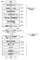
図2に示すフローチャートを参照して、続いて動作手順の説明を述べる。図2は、バーコード処理の全体像を示すフローチャートである。 Next, the operation procedure will be described with reference to the flowchart shown in FIG. FIG. 2 is a flowchart showing an overall image of barcode processing.
まずは可視光スキャナ側の動作手順から説明する。 First, the operation procedure on the visible light scanner side will be described.
可視光スキャナ1は、搬送ベルト8により搬送される書状9の画像を可視光により読み取る(ST1)。図3は、可視光スキャナ1により読み取られた第1の画像(可視光画像)の一例を示す図である。図3に示す第1の画像中の網掛け部分は書状に記載されていた模様等の画像(背景画像)に相当するものであり、点線で区切られた部分は蛍光バーコード用画像の印刷位置の一部である。つまり、点線で区切られた部分は蛍光バーコード用スキャナ2により読み取られる予定の位置である。 The visible light scanner 1 reads the image of the letter 9 conveyed by the conveying belt 8 with visible light (ST1). FIG. 3 is a diagram illustrating an example of a first image (visible light image) read by the visible light scanner 1. The shaded portion in the first image shown in FIG. 3 corresponds to an image (background image) such as a pattern described in the letter, and the portion separated by a dotted line is the printing position of the fluorescent barcode image. Is part of. That is, the part delimited by the dotted line is a position that is scheduled to be read by the
続いて、背景模様認識部4のエッジ検出部が、第1の画像に対してエッジ検出を行い(ST2)、書状に記載されていた模様等の画像(背景画像)を抽出する。エッジ検出手法に関しては、特に手法を制限する必要はないが、ここでは一例として、第1の画像を構成する複数画素の中の隣接画素の微分値から推定する手法を用いる。これは、縦横それぞれの方向に対して隣接画素の輝度の差を求め、輝度差が一定値以上のものをマーキングしておき、マーキングされたものが一定以上連結していたらエッジとして認識し、認識結果から位置と形状を得る。 Subsequently, the edge detection unit of the background pattern recognition unit 4 performs edge detection on the first image (ST2), and extracts an image (background image) such as a pattern described in the letter. As for the edge detection method, it is not necessary to limit the method in particular, but here, as an example, a method is used in which estimation is performed based on differential values of adjacent pixels in a plurality of pixels constituting the first image. This is to find the difference in brightness between adjacent pixels in the vertical and horizontal directions, mark the difference in luminance more than a certain value, and recognize the recognized edge as an edge if it is connected more than a certain value. The position and shape are obtained from the result.
なお、模様等の画像の抽出のためのエッジ検出処理は、住所認識、切手認識、及び料額印認識のためのエッジ検出処理を部分的に利用した処理であってもよいし、蛍光バーコード用画像の印刷領域だけに絞った特定のエッジ検出処理であってもよい。 The edge detection process for extracting an image such as a pattern may be a process partially using the edge detection process for address recognition, stamp recognition, and fee stamp recognition, or a fluorescent barcode. A specific edge detection process focused only on the print area of the image for use may be used.
このようにして、模様等の画像(背景画像)のエッジの位置と形状を推定したら(即ちエッジにより特定された特定背景画像の位置と形状を推定したら)、エッジで囲まれた内部(特定背景画像)を見て濃度の情報を得る。今回は濃度情報として、輝度平均値を得るものとする。カラー画像であれば、加えて、色情報も得るものとする。 Thus, when the position and shape of the edge of the image (background image) such as a pattern are estimated (that is, the position and shape of the specific background image specified by the edge are estimated), the inside (specific background) surrounded by the edge See the image) to obtain density information. This time, it is assumed that the luminance average value is obtained as the density information. If it is a color image, color information is also obtained.
特徴情報記憶部は、特定背景画像の濃度、位置、形状、色を含む特徴情報を記憶する(ST3)。特徴情報記憶部は、背景模様認識部4を構成するPC内のメモリである。或いは、特徴情報記憶部は、背景模様認識部4を構成するPCに接続されたハードディスクのような外部記憶装置であってもよい。また、図1に示すように、可視光スキャナ1に対応した背景模様認識部4と、蛍光バーコード用スキャナ2に対応した蛍光バーコード認識部5が別々に存在しているため、この時点で、背景模様認識部4の特徴情報記憶部(メモリ)に記憶された特徴情報を、蛍光バーコード認識部5に送信してもよいし、後で、背景模様認識部4の特徴情報記憶部(メモリ)に記憶された特徴情報を、蛍光バーコード認識部5に送信してもよい。 The feature information storage unit stores feature information including the density, position, shape, and color of the specific background image (ST3). The feature information storage unit is a memory in the PC constituting the background pattern recognition unit 4. Alternatively, the feature information storage unit may be an external storage device such as a hard disk connected to a PC constituting the background pattern recognition unit 4. Further, as shown in FIG. 1, since the background pattern recognition unit 4 corresponding to the visible light scanner 1 and the fluorescent
続いて、蛍光バーコード用スキャナ側の動作手順を説明する。 Next, the operation procedure on the fluorescent barcode scanner side will be described.
例えば、書状に印刷される蛍光バーコードは、4ステートバーコードである。つまり、蛍光バーコードは、短いタイミングバー、基準位置より上に伸びるアセンダー、基準位置より下に伸びるディセンダー、長いロングバーの4種類のバーにより構成されるものであり、リードソロモン式の復号により誤り訂正機能を備えている。 For example, a fluorescent barcode printed on a letter is a 4-state barcode. In other words, a fluorescent barcode is composed of four types of bars: a short timing bar, an ascender that extends above the reference position, a descender that extends below the reference position, and a long long bar. It has a correction function.
蛍光バーコード用スキャナ2は、搬送ベルト8により搬送される書状9の画像を不可視光により読み取る(ST4)。図4は、蛍光バーコード用スキャナ2により読み取られた第2の画像(蛍光バーコード画像)の一例を示す図である。第2の画像は、蛍光特性がある部分のみ発光する。このため、書状自体が蛍光特性を有しているものであれば、白い書状であったとしても撮影された画像は黒くなる。このような第2の画像から、可視光で検出したような模様等の画像(背景画像)を推定するのは難しい。ただし、図4に示すように、模様等の画像(背景画像)上に蛍光バーコードの一部が重ね打ちされた場合には、模様等の画像(背景画像)上の蛍光バーの一部が光らなくなる特性を持つ。本特性は、模様等の画像(背景画像)の色や濃度により大きく変化する。 The
次に、蛍光バーコード認識部5が背景模様認識部4と通信し、蛍光バーコード認識部5の特徴情報受信部が背景模様認識部4から送信される特徴情報を受信する(ST5)。なお、蛍光バーコード認識部5と背景模様認識部4との間の通信方式は特に問わない。このとき、可視光スキャナ1と蛍光バーコード用スキャナ2で解像度の差異などが発生している場合は、蛍光バーコード認識部5で第2の画像を処理できるように、座標の変換等を行っておく。 Next, the fluorescent
次に、可視光スキャナ1により取得した第1の画像から抽出された模様等の画像(背景画像)の特徴情報を利用した背景コントラスト調整手法について説明する。 Next, a background contrast adjustment method using feature information of an image (background image) such as a pattern extracted from the first image acquired by the visible light scanner 1 will be described.
蛍光バーコード認識部5の背景輝度調整部は、特徴情報を利用して第2の画像に含まれた背景画像領域のコントラスト差を広げる(ST6)。前述したように、模様等の画像(背景画像)と重ねて打たれたバーコードは、第2の画像上で薄くなってしまっているため、背景コントラスト調整により薄くなってしまっているバーコードを際立たせる。つまり、特徴情報を利用して、第2の画像に含まれる背景画像の存在位置および形状を確認し、背景画像の領域をコントラスト拡張領域とする。 The background luminance adjustment unit of the fluorescent
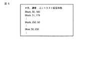
一方で、特徴情報に含まれた特定背景画像の濃度と色を示す情報から、コントラスト拡張係数を算出する。例えば、コントラスト拡張係数の一覧は、大量のデータを元に実験的に事前に求めておくもので、図5に示すようなリストである。つまり、所定の背景の色と濃度の変化に対応してこの所定の背景上に形成された蛍光バーコードの減衰度が変化するデータから算出されたコントラスト拡張係数の一覧を登録しておく。このコントラスト拡張係数の一覧を参照して、例えば背景の色が黒で背景の濃度が15の場合のコントラスト拡張係数を求める。コントラスト拡張係数が求められたら、輝度0からそのコントラスト拡張係数までの範囲を256階調(0〜255)に引き伸ばす処理をする。この処理は背景画像領域に対して実施する(或いは第2の画像全体に対して実施してもよい)。もし、引き伸ばし処理の際に、255を超えるようなケースがあれば、それは引き伸ばしによる飽和のため255にして良い。今回は引き伸ばし処理では線形変換を採用するが、非線形の変換でももちろん構わない。図6は、コントラスト拡張後の第2の画像の一例を示す図である。図6に示すように、減衰していたバーの鮮明度が向上しているのが分かる。 On the other hand, the contrast expansion coefficient is calculated from information indicating the density and color of the specific background image included in the feature information. For example, the list of contrast expansion coefficients is obtained in advance experimentally based on a large amount of data, and is a list as shown in FIG. That is, a list of contrast expansion coefficients calculated from data in which the attenuation of the fluorescent barcode formed on the predetermined background changes corresponding to changes in the color and density of the predetermined background is registered. With reference to this list of contrast expansion coefficients, for example, the contrast expansion coefficient when the background color is black and the background density is 15 is obtained. When the contrast expansion coefficient is obtained, a process from the luminance 0 to the contrast expansion coefficient is expanded to 256 gradations (0 to 255). This process is performed on the background image area (or may be performed on the entire second image). If there is a case that exceeds 255 in the stretching process, it may be set to 255 because of saturation due to stretching. This time, linear transformation is adopted for the enlargement processing, but non-linear transformation is of course acceptable. FIG. 6 is a diagram illustrating an example of the second image after contrast expansion. As shown in FIG. 6, it can be seen that the sharpness of the attenuated bar is improved.
次に、蛍光バーコード認識部5の通常微分二値ラベリング部が、第2の画像に対して通常微分二値ラベリング処理を実行する(ST7)。この通常微分二値ラベリング処理では、隣接画素との差分値によって二値化処理する。つまり、差分値が閾値以上の画素を検出し、差分値が閾値以上の画素の連結を一纏めにする(ラベリング)。ここでは、上述の差分値を判断する閾値は、画像全体に対する差分値ヒストグラムをとり、上位数%の部分が該当する差分値をそのまま閾値としている。特にこの通常微分二値ラベリング処理に関しては、画像全体の情報から微分二値ラベリングできれば手法は問わない。このラベリングにより、第2の画像から蛍光バーコードを構成する複数のバー候補が検出される。さらに、ラベリングで検出された複数のバーの候補のうち、一定サイズ以下のものをバー候補から除外する。つまり、ノイズ対策である。これにより、バー候補の検出精度を向上させることができ、結果的に蛍光バーコードの検出精度が向上する。 Next, the normal differential binary labeling unit of the fluorescent
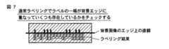
次に、エッジ検出部により検出された模様等の画像(背景画像)のエッジ(エッジの一部の直線)に、通常微分二値ラベリング部により検出された複数のバー候補のうちのどの程度の数のバー候補の一端が一致しているかを指標とする検出結果検証手法について説明する。具体的には、蛍光バーコード認識部5のラベリング結果確認部が、ラベリング結果が不自然でないかどうかを確認する(ST8)。例えば、エッジ検出部により検出された模様等の画像のエッジに、通常微分二値ラベリング部により検出された多くのバー候補の一端が一致していれば、蛍光バーコードとして不自然であると判断できる。つまり、図7に示すように、模様等の画像によってバーの輝度値が未だ減衰していてバーが適切に検出されていない場合には、ラベリングにより得られたバー候補の一端が模様等の画像のエッジに沿って並んでしまうからである。確認手法は、特徴情報により模様等の画像の位置、形状が判明しているため、個々のバー候補の一端が模様等の画像のエッジ部分に重なっているかどうかを見ることになる。 Next, on the edge of the image (background image) such as a pattern detected by the edge detection unit (a part of the straight line of the edge), how much of the plurality of bar candidates detected by the normal differential binary labeling unit A detection result verification method using as an index whether one end of a number of bar candidates matches will be described. Specifically, the labeling result confirmation unit of the fluorescent
例えば、エッジ上に一端が位置するバー候補の数をカウントし、ラベリング処理により検出されたバー候補の総数に対する、カウントされたバー候補の数の割合に基づきバー候補の再検出が必要か否か判断する。或いは、エッジ上に一端が位置するバー候補の数をカウントし、予め規定されたバーの総数(本来の蛍光バーコードを構成するバーの総数)に対する、カウントされたバー候補の数の割合に基づきバー候補の再検出が必要か否か判断する。或いは、エッジ上に一端が位置するバー候補の数をカウントし、カウントされたバー候補の数が所定数より多いか否かに基づきバー候補の再検出が必要か否か判断する。 For example, whether or not bar candidates need to be re-detected based on the ratio of the number of bar candidates counted to the total number of bar candidates detected by the labeling process after counting the number of bar candidates whose ends are located on the edge to decide. Alternatively, the number of bar candidates whose one end is located on the edge is counted, and based on the ratio of the number of counted bar candidates to the total number of bars (the total number of bars constituting the original fluorescent barcode) defined in advance. It is determined whether it is necessary to re-detect bar candidates. Alternatively, the number of bar candidates whose one end is located on the edge is counted, and it is determined whether or not bar candidates need to be re-detected based on whether or not the counted number of bar candidates is greater than a predetermined number.
再検出不要と判断されれば、つまりバー候補の検出結果に問題がない(バー候補は正しく検出されている)と判断されれば(ST8、NO)、次の背景ベース微分二値ラベリング処理(ST9)を飛ばして、さらに次の処理へ進む。 If it is determined that redetection is unnecessary, that is, if it is determined that there is no problem in the detection result of the bar candidate (the bar candidate is correctly detected) (ST8, NO), the next background-based differential binary labeling process ( Step ST9) is skipped, and further processing proceeds.
再検出必要と判断されれば、つまりバー候補の検出結果に問題がある(バー候補は正しく検出されていない)と判断されれば(ST8、YES)、蛍光バーコード認識部5の背景ベース微分二値ラベリング部が、特徴情報から再度微分二値化閾値を算出して第2の画像に対して再度ラベリング処理を実行する。つまり、背景ベース微分二値ラベリング処理を実行する(ST9)。前述した通常微分二値ラベリング部によるラベリング処理で使用された通常微分二値ラベリング閾値は、背景画像領域に特化したものでない。これに対して、背景ベース微分二値ラベリング部は、背景画像領域に特化した第2の閾値を算出する。 If it is determined that redetection is necessary, that is, if it is determined that there is a problem in the detection result of the bar candidate (the bar candidate is not correctly detected) (ST8, YES), the background-based differentiation of the fluorescent
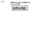
上記した特徴情報に含まれる模様等の画像の位置、形状を示す情報を参照すると、第2の画像上における模様等の画像の存在位置が分かり、模様等の画像の存在位置、つまり第2の画像に含まれる背景画像領域を閾値算出処理の領域とする。これは、前述したコントラスト拡張領域と同様のものである。この背景画像領域に限定して微分二値ラベリングのための第2の閾値を算出すると、第2の閾値は通常微分二値のための第1の閾値よりも低い値となる。例えば、通常微分二値ラベリング部による第1の閾値に基づくラベリング処理だけでは、背景画像によってバーが減衰していると高い輝度差は得られない。そこで、自動的に背景画像とバーを分離するような低い第2の閾値を使用して、再度、第2の画像の全体にラベリングを施す。これにより、図8に示すようなラベリングが可能となる。 By referring to the information indicating the position and shape of an image such as a pattern included in the feature information described above, the position where the image such as a pattern exists on the second image can be known. The background image area included in the image is set as a threshold calculation process area. This is the same as the contrast expansion region described above. When the second threshold value for differential binary labeling is calculated limited to this background image region, the second threshold value is lower than the first threshold value for normal differential binary value. For example, if only the labeling process based on the first threshold value by the normal differential binary labeling unit is used, a high luminance difference cannot be obtained if the bar is attenuated by the background image. Therefore, the entire second image is labeled again using a low second threshold value that automatically separates the background image and the bar. Thereby, labeling as shown in FIG. 8 becomes possible.
このとき、第2の閾値に基づく微分二値ラベリングを第2の画像の全体に適用して、第2の画像に含まれる背景画像領域以外の非背景画像領域部分でノイズが多くなるようであれば、第2の画像に含まれる背景画像領域に対しては第2の閾値を、第2の画像に含まれる非背景画像領域に対しては第1の閾値を適用する。これにより、ノイズの発生を抑えることができる。 At this time, if differential binary labeling based on the second threshold is applied to the entire second image, noise may increase in the non-background image region portion other than the background image region included in the second image. For example, the second threshold value is applied to the background image area included in the second image, and the first threshold value is applied to the non-background image area included in the second image. Thereby, generation | occurrence | production of noise can be suppressed.
本実施形態では、ここではバー候補の再検出時に第2の閾値によるラベリング処理を適用するものとしたが、最初のバー候補の検出時に第2の閾値によるラベリング処理を適用してもよい。 In the present embodiment, the labeling process using the second threshold is applied here when the bar candidate is redetected. However, the labeling process using the second threshold may be applied when the first bar candidate is detected.
次に、認識対象領域が抽出され(ST10)、認識対象領域の各バーが判定され(ST11)、判定結果に基づきバーコードが復号され(ST12)、バーコードが認識される(ST13、ST14)。この認識対象の領域抽出(ST10)から認識結果出力(ST14)までの処理は、例えば、図9のフローチャートに示す通りである。 Next, the recognition target area is extracted (ST10), each bar of the recognition target area is determined (ST11), the barcode is decoded based on the determination result (ST12), and the barcode is recognized (ST13, ST14). . Processing from this recognition target area extraction (ST10) to recognition result output (ST14) is, for example, as shown in the flowchart of FIG.
即ち、一定ピッチで規則的にバーが並んでいる部分を認識対象領域として検出する(ST10)。さらに、各バーの並びからバーのスキュー角度を検出し、さらに、各バーの長さや位置を見て、バーを4種に分類する(ST11)。 That is, a portion where bars are regularly arranged at a constant pitch is detected as a recognition target region (ST10). Further, the bar skew angle is detected from the arrangement of the bars, and the bars are classified into four types by looking at the length and position of each bar (ST11).
蛍光バーコード認識部5の復号部は、バーの並び順に従ってバーを復号する(ST12)。認識結果選択部は、複数手法を組み合わせて復号結果が多数得られた場合に、適切な復号結果を採用する(ST13)。例えば、未検出数と誤り訂正数を基準として選択される。 The decoding unit of the fluorescent
復号結果を得たら、蛍光バーコード認識部5の認識結果出力部が、区分機側およびログ情報等に認識結果を出力する(ST14)。 When the decoding result is obtained, the recognition result output unit of the fluorescent
以上により、模様等の画像(背景画像)によって、蛍光バーコードを構成する複数のバーの一部が検出できなくなるのを防止できる。その結果、背景画像によるバーコードの認識率低下を防止することができる。また、バー候補の検出の際に特徴情報を利用してバー候補の検出に用いる二値化処理の閾値を背景画像の影響によるバーの減衰も加味しながら自動的に逆算し、この閾値を利用する点も、これも背景画像によるバーコードの認識率低下の防止に大いに貢献している。 As described above, it is possible to prevent a part of a plurality of bars constituting the fluorescent barcode from being detected by an image (background image) such as a pattern. As a result, it is possible to prevent a reduction in the barcode recognition rate due to the background image. In addition, the threshold value of the binarization process used to detect the bar candidate using the feature information when detecting the bar candidate is automatically back-calculated taking into account the attenuation of the bar due to the influence of the background image, and this threshold value is used. This also contributes greatly to preventing a reduction in the barcode recognition rate due to the background image.
なお、本願発明は、上記実施形態に限定されるものではなく、実施段階ではその要旨を逸脱しない範囲で種々に変形することが可能である。また、各実施形態は可能な限り適宜組み合わせて実施してもよく、その場合組み合わせた効果が得られる。更に、上記実施形態には種々の段階の発明が含まれており、開示される複数の構成要件における適当な組み合わせにより種々の発明が抽出され得る。例えば、実施形態に示される全構成要件からいくつかの構成要件が削除されても、発明が解決しようとする課題の欄で述べた課題が解決でき、発明の効果の欄で述べられている効果が得られる場合には、この構成要件が削除された構成が発明として抽出され得る。 Note that the present invention is not limited to the above-described embodiment, and various modifications can be made without departing from the scope of the invention in the implementation stage. In addition, the embodiments may be appropriately combined as much as possible, and in that case, the combined effect can be obtained. Further, the above embodiments include inventions at various stages, and various inventions can be extracted by appropriately combining a plurality of disclosed constituent elements. For example, even if some constituent requirements are deleted from all the constituent requirements shown in the embodiment, the problem described in the column of the problem to be solved by the invention can be solved, and the effect described in the column of the effect of the invention Can be obtained as an invention.
1…可視光スキャナ、2…蛍光バーコード用スキャナ、3…制御部、4…背景模様認識部、5…蛍光バーコード認識部、6…HUB、7…通信ケーブル、8…搬送ベルトDESCRIPTION OF SYMBOLS 1 ... Visible light scanner, 2 ... Fluorescent barcode scanner, 3 ... Control part, 4 ... Background pattern recognition part, 5 ... Fluorescence barcode recognition part, 6 ... HUB, 7 ... Communication cable, 8 ... Conveyor belt
Claims (17)
Translated fromJapanese不可視光により前記読取対象物から画像を読み取る第2の画像読取手段と、
前記第1の画像読取手段により読み取られた第1の読取画像から、前記読取対象物に含まれていた背景画像のうちの少なくとも一部の背景画像を検出する第1の検出手段と、
前記第1の検出手段により検出された前記背景画像の特徴を示す特徴情報を登録する登録手段と、
前記登録手段に登録された前記特徴情報に基づき、前記第2の画像読取手段により読み取られた第2の読取画像に含まれていた、前記背景画像のうちの少なくとも一部の背景画像に対応した背景画像領域のコントラストを強調し、前記第2の読取画像からコード情報を示す画像を検出する第2の検出手段と、
を備えたことを特徴とする画像処理装置。First image reading means for reading an image from a reading object with visible light;
Second image reading means for reading an image from the reading object with invisible light;
First detection means for detecting at least a part of a background image included in the reading object from a first read image read by the first image reading means;
Registration means for registering feature information indicating features of the background image detected by the first detection means;
Based on the feature information registered in the registration unit, corresponding to at least some of the background images included in the second read image read by the second image reading unit. Second detection means for enhancing contrast of a background image region and detecting an image indicating code information from the second read image;
An image processing apparatus comprising:
不可視光により前記読取対象物から蛍光画像を読み取る第2の画像読取手段と、
前記第1の画像読取手段により読み取られた第1の読取画像から、前記読取対象物に含まれていた背景画像のうちの少なくとも一部の背景画像を検出する第1の検出手段と、
前記第1の検出手段により検出された検出背景画像の特徴を示す特徴情報を登録する登録手段と、
前記登録手段に登録された前記特徴情報に基づき、前記第2の画像読取手段により読み取られた第2の読取画像に含まれていた、前記背景画像のうちの少なくとも一部の背景画像に対応した背景画像領域のコントラストを強調し、前記第2の読取画像から蛍光バーコードを検出する第2の検出手段と、
を備えたことを特徴とするバーコード処理装置。First image reading means for reading an image from a reading object with visible light;
A second image reading means for reading a fluorescent image from the reading object with invisible light;
First detection means for detecting at least a part of a background image included in the reading object from a first read image read by the first image reading means;
Registration means for registering feature information indicating features of the detected background image detected by the first detection means;
Based on the feature information registered in the registration unit, corresponding to at least some of the background images included in the second read image read by the second image reading unit. Second detection means for enhancing a contrast of a background image region and detecting a fluorescent barcode from the second read image;
A bar code processing apparatus comprising:
前記第2の検出手段は、前記登録手段に登録された前記特徴情報に含まれた前記検出背景画像の位置及び形状を示す情報に基づき、前記第2の読取画像に含まれた前記背景画像領域のコントラストを強調し、前記第2の読取画像から前記蛍光バーコードを検出することを特徴とする請求項2に記載のバーコード処理装置。The registration unit registers the feature information including information indicating a position and a shape of the detected background image,
The second detection unit includes the background image region included in the second read image based on information indicating the position and shape of the detected background image included in the feature information registered in the registration unit. The barcode processing apparatus according to claim 2, wherein the contrast is enhanced and the fluorescent barcode is detected from the second read image.
前記第2の検出手段は、前記登録手段に登録された前記特徴情報に含まれた前記検出背景画像の色を示す情報に基づき、前記第2の読取画像に含まれた前記背景画像領域のコントラストの調整範囲を算出し、算出結果に基づき前記背景画像領域のコントラストを強調し、前記第2の読取画像から前記蛍光バーコードを検出することを特徴とする請求項2に記載のバーコード処理装置。The registration means registers the feature information including information indicating a color of the detected background image;
The second detection means is based on information indicating the color of the detected background image included in the feature information registered in the registration means, and the contrast of the background image area included in the second read image. 3. The barcode processing apparatus according to claim 2, wherein the adjustment range is calculated, the contrast of the background image region is enhanced based on the calculation result, and the fluorescent barcode is detected from the second read image. .
前記第2の検出手段は、前記登録手段に登録された前記特徴情報に含まれた前記検出背景画像の濃度を示す情報に基づき、前記第2の読取画像に含まれた前記背景画像領域のコントラストの調整範囲を算出し、算出結果に基づき前記背景画像領域のコントラストを強調し、前記第2の読取画像から前記蛍光バーコードを検出することを特徴とする請求項2に記載のバーコード処理装置。The registration unit registers the feature information including information indicating a density of the detected background image;
The second detection means is based on information indicating the density of the detected background image included in the feature information registered in the registration means, and the contrast of the background image area included in the second read image. 3. The barcode processing apparatus according to claim 2, wherein the adjustment range is calculated, the contrast of the background image region is enhanced based on the calculation result, and the fluorescent barcode is detected from the second read image. .
前記第2の検出手段は、前記特徴情報に含まれた前記検出背景画像の色と濃度を示す情報に基づき、前記第2の読取画像に含まれた前記背景画像領域のコントラストの調整範囲を算出し、このコントラスト調整範囲及び前記コントラスト拡張係数に基づき前記背景画像領域のコントラストを強調し、前記第2の読取画像から前記蛍光バーコードを検出することを特徴とする請求項2に記載のバーコード処理装置。The registration means registers a contrast coefficient for each background condition calculated from data in which the attenuation of the fluorescent barcode formed on the predetermined background changes corresponding to a change in color and density of the predetermined background. And registering the feature information including information indicating the color and density of the detected background image,
The second detection unit calculates a contrast adjustment range of the background image area included in the second read image based on information indicating the color and density of the detected background image included in the feature information. 3. The barcode according to claim 2, wherein contrast of the background image region is enhanced based on the contrast adjustment range and the contrast expansion coefficient, and the fluorescent barcode is detected from the second read image. Processing equipment.
不可視光により前記読取対象物から蛍光画像を読み取る第2の画像読取手段と、
前記第1の画像読取手段により読み取られた第1の読取画像から、前記読取対象物に含まれていた背景画像のうちの少なくとも一部の背景画像を検出する第1の検出手段と、
前記第1の検出手段により検出された検出背景画像の特徴を示す特徴情報を登録する登録手段と、
前記登録手段に登録された前記特徴情報に基づき前記第2の画像読取手段により読み取られた第2の読取画像を処理し、第1のラベリング処理により前記第2の読取画像から蛍光バーコードを構成する複数のバー候補を検出し、検出された複数のバー候補の一端の位置に基づきバー候補の再検出が必要か否か判断し、再検出が必要と判断された場合には、第2のラベリング処理により前記第2の読取画像から前記複数のバー候補を検出する第2の検出手段と、
を備えたことを特徴とするバーコード処理装置。First image reading means for reading an image from a reading object with visible light;
A second image reading means for reading a fluorescent image from the reading object with invisible light;
First detection means for detecting at least a part of a background image included in the reading object from a first read image read by the first image reading means;
Registration means for registering feature information indicating features of the detected background image detected by the first detection means;
A second read image read by the second image reading unit is processed based on the feature information registered in the registration unit, and a fluorescent barcode is formed from the second read image by a first labeling process. A plurality of bar candidates to be detected, and it is determined whether or not bar candidates need to be redetected based on the position of one end of the detected plurality of bar candidates. Second detection means for detecting the plurality of bar candidates from the second read image by labeling processing;
A bar code processing apparatus comprising:
前記第2の検出手段は、前記登録手段に登録された前記特徴情報に含まれた前記検出背景画像の位置及び形状を示す情報に基づき前記第2の読取画像を処理することを特徴とする請求項7に記載のバーコード処理装置。The registration unit registers the feature information including information indicating a position and a shape of the detected background image,
The second detection unit processes the second read image based on information indicating a position and a shape of the detected background image included in the feature information registered in the registration unit. Item 8. The barcode processing apparatus according to Item 7.
不可視光により前記読取対象物から蛍光画像を読み取る第2の画像読取手段と、
前記第1の画像読取手段により読み取られた第1の読取画像から、前記読取対象物に含まれていた背景画像のうちの少なくとも一部の背景画像を検出する第1の検出手段と、
前記第1の検出手段により検出された検出背景画像の特徴を示す特徴情報を登録する登録手段と、
前記登録手段に登録された前記特徴情報に基づき、前記第2の画像読取手段により読み取られた第2の読取画像に含まれていた、前記背景画像のうちの少なくとも一部の背景画像に対応した背景画像領域から得られる情報に基づき、前記第2の読取画像から蛍光バーコードを検出するための二値化閾値を算出し、この二値化閾値に基づく二値化処理により前記第2の読取画像から前記蛍光バーコードを検出する第2の検出手段と、
を備えたことを特徴とするバーコード処理装置。First image reading means for reading an image from a reading object with visible light;
A second image reading means for reading a fluorescent image from the reading object with invisible light;
First detection means for detecting at least a part of a background image included in the reading object from a first read image read by the first image reading means;
Registration means for registering feature information indicating features of the detected background image detected by the first detection means;
Based on the feature information registered in the registration unit, corresponding to at least some of the background images included in the second read image read by the second image reading unit. Based on the information obtained from the background image area, a binarization threshold for detecting a fluorescent barcode is calculated from the second read image, and the second reading is performed by binarization processing based on the binarization threshold. Second detection means for detecting the fluorescent barcode from an image;
A bar code processing apparatus comprising:
前記登録手段に登録された前記特徴情報に基づき前記第2の読取画像のうちの前記背景画像領域と異なる非背景画像領域から得られる情報に基づき、前記第2の読取画像から前記蛍光バーコードを検出するための第1の二値化閾値を算出し、
前記登録手段に登録された前記特徴情報に基づき前記第2の読取画像のうちの前記背景画像領域から得られる情報に基づき、前記第2の読取画像から前記蛍光バーコードを検出するための第2の二値化閾値を算出し、
前記第1の二値化閾値に基づく二値化処理を前記第2の読取画像のうちの前記非背景画像領域に適用し、前記第2の読取画像に含まれた前記非背景画像領域から前記蛍光バーコードの一部を検出し、
前記第2の二値化閾値に基づく二値化処理を前記第2の読取画像のうちの前記背景画像領域に適用し、前記第2の読取画像に含まれた前記背景画像領域から前記蛍光バーコードの一部を検出し、
前記非背景画像領域から検出された前記蛍光バーコードの一部と前記背景画像領域から検出された前記蛍光バーコードの一部に基づき、前記蛍光バーコードを検出する、
ことを特徴とする請求項13に記載のバーコード処理装置。The second detection means includes
Based on the information obtained from the non-background image area different from the background image area of the second read image based on the feature information registered in the registration means, the fluorescent barcode is extracted from the second read image. Calculating a first binarization threshold for detection;
A second for detecting the fluorescent barcode from the second read image based on information obtained from the background image area of the second read image based on the feature information registered in the registration means. Calculate the binarization threshold of
A binarization process based on the first binarization threshold is applied to the non-background image region of the second read image, and the non-background image region included in the second read image Detect a part of the fluorescent barcode,
A binarization process based on the second binarization threshold is applied to the background image area of the second read image, and the fluorescence bar is detected from the background image area included in the second read image. Detect part of the code,
Detecting the fluorescent barcode based on a part of the fluorescent barcode detected from the non-background image region and a part of the fluorescent barcode detected from the background image region;
The barcode processing apparatus according to claim 13.
前記画像処理装置の第1の検出手段が、第1の画像読取手段で可視光により読み取られた第1の読取画像から、前記読取対象物に含まれていた背景画像のうちの少なくとも一部の背景画像を検出し、
前記画像処理装置の登録手段が、前記検出された前記背景画像の特徴を示す特徴情報を登録し、
前記画像処理装置の第2の検出手段が、前記登録された前記特徴情報に基づき、第2の画像読取手段で不可視光により読み取られた第2の読取画像に含まれていた、前記背景画像のうちの少なくとも一部の背景画像に対応した背景画像領域のコントラストを強調し、前記第2の読取画像からコード情報を示す画像を検出する、
ことを特徴とする画像処理方法。An image processing method executed by an image processing apparatus,
The first detection unit of the image processing apparatus uses at least a part of a background image included in the reading object from a first read image read by visible light bythe first image reading unit . Detect background image,
A registration unit of the image processing apparatus registers feature information indicating a feature of the detected background image;
The second detection unit of the image processing device includes the background image included in the second read image read by the secondimage reading unit with invisible light based on the registered feature information. Enhancing the contrast of a background image area corresponding to at least a portion of the background image, and detecting an image indicating code information from the second read image;
An image processing method.
Priority Applications (4)
| Application Number | Priority Date | Filing Date | Title |
|---|---|---|---|
| JP2008133334AJP5214330B2 (en) | 2008-05-21 | 2008-05-21 | Image processing apparatus, barcode processing apparatus, and image processing method |
| EP09003572.6AEP2124168B1 (en) | 2008-05-21 | 2009-03-11 | Image processing apparatus, bar code processing apparatus, and image processing method |
| US12/404,552US7905412B2 (en) | 2008-05-21 | 2009-03-16 | Bar code processing apparatus |
| KR1020090022105AKR101024176B1 (en) | 2008-05-21 | 2009-03-16 | Image processing apparatus, bar code processing apparatus, and image processing method |
Applications Claiming Priority (1)
| Application Number | Priority Date | Filing Date | Title |
|---|---|---|---|
| JP2008133334AJP5214330B2 (en) | 2008-05-21 | 2008-05-21 | Image processing apparatus, barcode processing apparatus, and image processing method |
Publications (2)
| Publication Number | Publication Date |
|---|---|
| JP2009282691A JP2009282691A (en) | 2009-12-03 |
| JP5214330B2true JP5214330B2 (en) | 2013-06-19 |
Family
ID=41056819
Family Applications (1)
| Application Number | Title | Priority Date | Filing Date |
|---|---|---|---|
| JP2008133334AExpired - Fee RelatedJP5214330B2 (en) | 2008-05-21 | 2008-05-21 | Image processing apparatus, barcode processing apparatus, and image processing method |
Country Status (4)
| Country | Link |
|---|---|
| US (1) | US7905412B2 (en) |
| EP (1) | EP2124168B1 (en) |
| JP (1) | JP5214330B2 (en) |
| KR (1) | KR101024176B1 (en) |
Families Citing this family (23)
| Publication number | Priority date | Publication date | Assignee | Title |
|---|---|---|---|---|
| GB2477951B (en)* | 2010-02-19 | 2013-04-10 | Innovia Films Sarl | Article tracking method |
| SMT201900157T1 (en) | 2010-07-22 | 2019-05-10 | K Fee System Gmbh | Portion capsule having an identifier |
| JP5740212B2 (en)* | 2011-06-08 | 2015-06-24 | 理想科学工業株式会社 | Image processing apparatus, image processing method, and image processing program |
| JP5834879B2 (en)* | 2011-12-19 | 2015-12-24 | 富士通株式会社 | Image printing apparatus, method, program, image processing apparatus, method, and program |
| US8919653B2 (en)* | 2012-07-19 | 2014-12-30 | Datalogic ADC, Inc. | Exception handling in automated data reading systems |
| CN103577823B (en)* | 2012-08-02 | 2018-02-09 | 比亚迪股份有限公司 | Binarization method and device are carried out to bar code |
| DE102012223291A1 (en) | 2012-12-14 | 2014-06-18 | K-Fee System Gmbh | Portion capsule and method of making a beverage with a portion capsule |
| US10430776B2 (en) | 2014-01-09 | 2019-10-01 | Datalogic Usa, Inc. | System and method for exception handling in self-checkout and automated data capture systems |
| WO2016135105A1 (en) | 2015-02-27 | 2016-09-01 | K-Fee System Gmbh | Single serve capsule comprising a filter element connected thereto by sealing |
| CN106156673A (en)* | 2015-03-31 | 2016-11-23 | 上海通路快建网络服务外包有限公司 | Intelligent tagging systems and update method |
| PT3307647T (en) | 2015-06-10 | 2019-10-28 | K Fee System Gmbh | Capsule with a three layer fleece |
| WO2017009369A1 (en) | 2015-07-13 | 2017-01-19 | K-Fee System Gmbh | Filter element having a cut-out |
| WO2017046352A1 (en) | 2015-09-18 | 2017-03-23 | K-Fee System Gmbh | Adapter for a single serve capsule |
| US10055626B2 (en) | 2016-12-06 | 2018-08-21 | Datalogic Usa, Inc. | Data reading system and method with user feedback for improved exception handling and item modeling |
| US10402611B2 (en)* | 2017-09-05 | 2019-09-03 | Datalogic Usa Inc. | Automated modification of imaging scanner function based on orientation |
| CN108896545B (en)* | 2018-05-09 | 2021-07-13 | 歌尔光学科技有限公司 | Glue detection method, device and computer readable storage medium |
| US12227323B2 (en) | 2018-07-27 | 2025-02-18 | Gcs German Capsule Solution Gmbh | Method for producing a portion capsule |
| JP7021651B2 (en)* | 2019-03-01 | 2022-02-17 | オムロン株式会社 | Symbol boundary identification device, symbol boundary identification method and image processing program |
| US11775786B2 (en) | 2020-09-30 | 2023-10-03 | United States Postal Service | System and method for extracting a region of interest from a captured image of a mailpiece or parcel label |
| WO2022098545A2 (en) | 2020-11-04 | 2022-05-12 | Verifyme, Inc. | Remote infrared ink reader and authenticator |
| US11755858B2 (en) | 2020-12-04 | 2023-09-12 | United States Postal Service | System and method for extracting a computer readable code from a captured image of a distribution item |
| JP7613244B2 (en)* | 2021-04-27 | 2025-01-15 | 株式会社リコー | Position detection device, image forming device, and position detection method |
| US12136017B2 (en) | 2022-04-28 | 2024-11-05 | United States Postal Service | System and method for detecting an address block and barcode on a captured image of item, and reading the detected barcode using connected component analysis |
Family Cites Families (7)
| Publication number | Priority date | Publication date | Assignee | Title |
|---|---|---|---|---|
| US20020186874A1 (en)* | 1994-09-07 | 2002-12-12 | Jeffrey H. Price | Method and means for image segmentation in fluorescence scanning cytometry |
| AU3582197A (en)* | 1996-06-28 | 1998-01-21 | Battelle Memorial Institute | Edge effect compensating bar code reader |
| JP2004246795A (en) | 2003-02-17 | 2004-09-02 | Toshiba Social Automation Systems Co Ltd | Bar code recognition method and recognition device |
| US7229025B2 (en)* | 2004-06-07 | 2007-06-12 | Pitney Bowes Inc. | Barcode with enhanced additional stored data |
| US7337970B2 (en)* | 2004-12-03 | 2008-03-04 | Symbol Technologies, Inc. | Barcode scanner decoding |
| WO2006074123A2 (en)* | 2005-01-05 | 2006-07-13 | United States Postal Service | System and method for image lift with enhanced image capture |
| JP4650204B2 (en)* | 2005-10-24 | 2011-03-16 | 富士ゼロックス株式会社 | Image processing device |
- 2008
- 2008-05-21JPJP2008133334Apatent/JP5214330B2/ennot_activeExpired - Fee Related
- 2009
- 2009-03-11EPEP09003572.6Apatent/EP2124168B1/ennot_activeCeased
- 2009-03-16KRKR1020090022105Apatent/KR101024176B1/ennot_activeExpired - Fee Related
- 2009-03-16USUS12/404,552patent/US7905412B2/ennot_activeExpired - Fee Related
Also Published As
| Publication number | Publication date |
|---|---|
| KR101024176B1 (en) | 2011-03-22 |
| JP2009282691A (en) | 2009-12-03 |
| US7905412B2 (en) | 2011-03-15 |
| KR20090121191A (en) | 2009-11-25 |
| EP2124168A2 (en) | 2009-11-25 |
| EP2124168B1 (en) | 2016-11-09 |
| EP2124168A3 (en) | 2010-09-15 |
| US20090289121A1 (en) | 2009-11-26 |
Similar Documents
| Publication | Publication Date | Title |
|---|---|---|
| JP5214330B2 (en) | Image processing apparatus, barcode processing apparatus, and image processing method | |
| US9008431B2 (en) | Character string extraction method and character string extraction device | |
| JP5591578B2 (en) | Character string recognition apparatus and character string recognition method | |
| JP6139658B2 (en) | Character recognition method and character recognition system | |
| JP4658848B2 (en) | Character string recognition method and character string recognition apparatus | |
| JP6171167B2 (en) | Character recognition device, character recognition method, and character recognition program | |
| US20050271275A1 (en) | Text character identification system and method thereof | |
| JP4945739B2 (en) | Character string recognition method and character string recognition apparatus | |
| US20090304233A1 (en) | Recognition apparatus and recognition method | |
| US8200016B2 (en) | Method and apparatus for character string recognition | |
| US11430235B2 (en) | Image processing apparatus, image processing method, and storage medium | |
| JP5630689B2 (en) | Character recognition method and character recognition device | |
| US20110170133A1 (en) | Image forming apparatus, method of forming image and method of authenticating document | |
| KR20010044743A (en) | A method for recognizing 2D barcode information | |
| JP2008084105A (en) | Character cutout method and character recognition device | |
| JP4832996B2 (en) | Information detection device | |
| JP6039944B2 (en) | Form type discriminating apparatus and form type discriminating method | |
| JP5604284B2 (en) | Paper piece identification system, paper piece identification device | |
| KR100341601B1 (en) | A method for recognizing 2D bar code information | |
| JPH10207978A (en) | Pattern matching method and device for characters etc. | |
| JP2013077306A (en) | Targeted object recognition device and targeted object recognition method | |
| US8428303B2 (en) | Postal indicium detection method and postal indicium detection apparatus | |
| EP2945099B1 (en) | Character presence determination system and character presence determination method | |
| JP2010073047A (en) | Information processor and program |
Legal Events
| Date | Code | Title | Description |
|---|---|---|---|
| A621 | Written request for application examination | Free format text:JAPANESE INTERMEDIATE CODE: A621 Effective date:20110127 | |
| A977 | Report on retrieval | Free format text:JAPANESE INTERMEDIATE CODE: A971007 Effective date:20120719 | |
| A131 | Notification of reasons for refusal | Free format text:JAPANESE INTERMEDIATE CODE: A131 Effective date:20120821 | |
| A521 | Written amendment | Free format text:JAPANESE INTERMEDIATE CODE: A523 Effective date:20121022 | |
| A131 | Notification of reasons for refusal | Free format text:JAPANESE INTERMEDIATE CODE: A131 Effective date:20121113 | |
| A521 | Written amendment | Free format text:JAPANESE INTERMEDIATE CODE: A523 Effective date:20130115 | |
| TRDD | Decision of grant or rejection written | ||
| A01 | Written decision to grant a patent or to grant a registration (utility model) | Free format text:JAPANESE INTERMEDIATE CODE: A01 Effective date:20130205 | |
| A61 | First payment of annual fees (during grant procedure) | Free format text:JAPANESE INTERMEDIATE CODE: A61 Effective date:20130227 | |
| FPAY | Renewal fee payment (event date is renewal date of database) | Free format text:PAYMENT UNTIL: 20160308 Year of fee payment:3 | |
| LAPS | Cancellation because of no payment of annual fees |