JP5213086B1 - Exercise assistance device - Google Patents
Exercise assistance deviceDownload PDFInfo
- Publication number
- JP5213086B1 JP5213086B1JP2012553115AJP2012553115AJP5213086B1JP 5213086 B1JP5213086 B1JP 5213086B1JP 2012553115 AJP2012553115 AJP 2012553115AJP 2012553115 AJP2012553115 AJP 2012553115AJP 5213086 B1JP5213086 B1JP 5213086B1
- Authority
- JP
- Japan
- Prior art keywords
- user
- holding
- main body
- trapezoidal
- movement
- Prior art date
- Legal status (The legal status is an assumption and is not a legal conclusion. Google has not performed a legal analysis and makes no representation as to the accuracy of the status listed.)
- Active
Links
Images


Landscapes
- Rehabilitation Tools (AREA)
Abstract
Translated fromJapaneseDescription
Translated fromJapanese本発明は、走行や歩行等の踏込み時における重心移動のトレーニングに適した運動補助装置に関する。 The present invention relates to an exercise assisting device suitable for training of movement of the center of gravity when stepping on running, walking, or the like.
一般に、健康維持(生活習慣病の改善)や競技力向上には有酸素運動によって体脂肪を減少させて、糖代謝を促進することが有効である。すなわち、筋肉のエネルギ源であるブドウ糖を筋肉に取り込んで燃焼させれば、余剰のブドウ糖が消費され、高血糖、高インスリン血症の改善の結果、生活習慣病(糖尿病、肥満、高脂血症など)の改善に寄与することになる。
筋肉への余剰ブドウ糖の取り込みは筋収縮によって生じ、筋肉へのブドウ糖の取り込み量を増加させれば、糖代謝を促進することが可能になる。In general, to maintain health (improve lifestyle-related diseases) and improve competitiveness, it is effective to reduce body fat by aerobic exercise and promote glucose metabolism. That is, if glucose, which is a source of muscle energy, is taken into the muscles and burned, excess glucose is consumed, and as a result of improvement in hyperglycemia and hyperinsulinemia, lifestyle-related diseases (diabetes, obesity, hyperlipidemia) Etc.).
Incorporation of excess glucose into muscle is caused by muscle contraction. If the amount of glucose uptake into muscle is increased, sugar metabolism can be promoted.
筋収縮による糖代謝を効率的に行うには、体積の大きい筋肉に筋収縮を生じさせることが望ましく、股関節を伸屈させて体幹から大腿部にかけての大筋群を筋収縮させることが有効と考えられる。
大筋群を収縮させる運動にランニングやウォーキング等があるが、それらを模した装置として、トレッドミルが一般的に知られている。In order to efficiently perform glucose metabolism by muscle contraction, it is desirable to cause muscle contraction in muscles with a large volume, and it is effective to contract the large muscle group from the trunk to the thigh by stretching the hip joint it is conceivable that.
There are running, walking, and the like as exercises for contracting the major muscle groups, and a treadmill is generally known as a device that imitates them.
このトレッドミルは、歩行又は走行面である移動ベルトの回転速度や傾斜角度が調節可能な運動補助装置である。又、全身持久力のトレーニングを目的として、トレッドミル上での走行や歩行運動が行われることも多い。
一方、これらトレッドミルとは別の、ランニングやウォーキングの模擬を意図した運動補助装置として、特許文献1に記載された車軸移動式自転車エルゴメータが知られている。
このエルゴメータは、左右一対のペダル及びアームによりそれぞれ回転力が与えられる一対の回転軸と、この一対の回転軸をそれぞれ水平方向に支持する一対の台座と、一対の台座を一対の回転軸と直交する向きにそれぞれ往復動可能に支持する一対のガイド部と、一対の台座を回転軸の回転角に基づいて一対のガイド部上を移動させる一対の移動機構と、一対の回転軸の制動をそれぞれ行う制動機構とを備えている(特許文献1参照)。This treadmill is an exercise assisting device capable of adjusting the rotational speed and inclination angle of a moving belt that is a walking or running surface. In addition, running and walking exercises on a treadmill are often performed for the purpose of training for endurance of the whole body.
On the other hand, an axle-moving bicycle ergometer described in Patent Document 1 is known as an exercise assisting device intended to simulate running and walking, which is different from these treadmills.
The ergometer includes a pair of rotating shafts to which a rotational force is applied by a pair of left and right pedals and arms, a pair of pedestals that respectively support the pair of rotating shafts in a horizontal direction, and a pair of pedestals orthogonal to the pair of rotating shafts. A pair of guide portions that are supported so as to be reciprocally movable, a pair of moving mechanisms that move the pair of bases on the pair of guide portions based on the rotation angle of the rotation shaft, and braking of the pair of rotation shafts, respectively. The brake mechanism to perform is provided (refer patent document 1).
しかしながら、上述した従来の運動補助装置には、次のような問題があった。
トレッドミルは、一見、使用者が走っているように見えるが、実は斜め前上方に飛び上がっているだけであり、例え速度を上げても斜め前上方に高く飛んでしまえばこなせてしまうものである。その結果として、使用者のふくらはぎなど末端部のみ運動になりやすい。
更に、トレッドミルは、屋外におけるウォーキングやランニングを代替する運動が室内で出来るように作られた運動補助装置であるものの、実際の歩く動作や走る動作とは異なることが大きな問題である。However, the above-described conventional exercise assistance device has the following problems.
At first glance, the treadmill looks like the user is running, but it is actually just jumping up diagonally forward, and even if you increase the speed, you can do it if you fly high up diagonally forward. . As a result, only the end portion such as the user's calf tends to move.
Furthermore, although the treadmill is an exercise assisting device that can be used indoors to perform exercises that replace outdoor walking and running, it is a big problem that it differs from actual walking and running operations.
一方、特許文献1に記載された車軸移動式自転車エルゴメータを用いた実際の動作における足部の運動軌跡は、ペダルアーム回転軸が前後に水平移動する円運動(車軸移動型ペダリング)の回転円周上をたどるものとなり、一見して、実際の走動作の軌跡と運動軌跡が異なる(特許文献1の図5、6、段落0036参照)。
更に、特許文献1のエルゴメータは、台座に着座してペダルを漕ぐに過ぎないことから、使用者の足の動きにしか着目しておらず、体幹と脚(上半身と下半身)を連動させた動きを、使用者にさせることは出来ず、当然に、着座した使用者は、重心の前方移動、つまり、「骨盤を前に送りながらの重心移動」が出来ない。On the other hand, the movement trajectory of the foot in the actual operation using the axle movement type bicycle ergometer described in Patent Document 1 is the rotation circumference of the circular movement (axle movement type pedaling) in which the pedal arm rotation axis moves horizontally back and forth. At first glance, the trajectory of the actual running motion is different from the motion trajectory (see FIGS. 5 and 6 and paragraph 0036 of Patent Document 1).
Furthermore, since the ergometer of Patent Document 1 only sits on a pedestal and squeezes the pedal, it focuses only on the movement of the user's foot and links the trunk and legs (upper body and lower body). The user cannot make the movement. Naturally, the seated user cannot move the center of gravity forward, that is, “move the center of gravity while feeding the pelvis forward”.
これら従来の運動補助装置に共通する問題点としては、上述したランニング、ウォーキング等の実動作(踏込み)とは異なること、使用者は末端部を大きく動かすなどのため、体幹部(大筋群)の動きが小さくなり有酸素運動の効果が低いことが挙げられる。
本発明は、このような問題点に鑑みて、体幹を保持された使用者が重心を前方移動させる時に、本体に対して台状体や保持体を移動させて、使用者の前傾を規制することで、走る、歩くなどの実動作に限りなく近い動作が可能となり、重心移動を伴った体幹(大筋群)中心の動きをさせて、使用者を問わずに有酸素運動のトレーニング効果を向上させることが出来る運動補助装置を提供することを目的とする。The problems common to these conventional exercise assisting devices are that they are different from the actual operations (stepping) such as running and walking described above, and the user moves the end part greatly. It is mentioned that the movement becomes smaller and the effect of aerobic exercise is low.
In view of such a problem, the present invention moves the trapezoidal body and the holding body relative to the main body when the user holding the trunk moves the center of gravity forward, thereby tilting the user forward. By regulating it, it is possible to move as much as possible to the actual movement such as running and walking, and the movement of the center of the trunk (major muscle group) with the movement of the center of gravity makes the movement of aerobic exercise regardless of the user It aims at providing the exercise assistance device which can improve an effect.
本発明に係る運動補助装置は、使用者Sが踏む台状体2と、この台状体2を下方から支持する本体3と、この本体3の上方に配設された保持体4を有していて、この保持体4で前記台状体2を踏む位置Fより前方に重心Gがある使用者Sの体幹Tを保持する運動補助装置であって、前記体幹Tを保持された使用者Sが台状体2の前記踏む位置Fを踏み込みながら重心Gを前方移動させる時に、前記本体3に対して台状体2を上下移動させ且つ前記本体3に対して保持体4を前後移動させて、前記使用者Sの前傾を規制していることを第1の特徴とする。 The exercise assisting apparatus according to the present invention includes a
本発明に係る運動補助装置の第2の特徴は、上記第1の特徴に加えて、前記台状体2は、前記本体3に対して上下揺動自在に枢支され、前記保持体4は、前記本体3に対して前後揺動自在に枢支され且つ前記使用者Sの体幹Tを前方から当接して保持し、前記台状体2と保持体4を枢支連結し且つ前記本体3に対して揺動自在に枢支されたリンク体5で、前記台状体2の上下揺動を保持体4の前後揺動に変換して、前記使用者Sの前傾を規制している点である。 A second feature of the exercise assisting device according to the present invention is that, in addition to the first feature, the
本発明に係る運動補助装置の第3の特徴は、上記第1の特徴に加えて、前記台状体2は、前記本体3に対して上下移動自在に支持リンク6を介して連結され、前記保持体4は、前記本体3に対して前後直動自在に支持され且つ前記使用者Sの体幹Tを前方から当接して保持し、前記台状体2と保持体4を枢支連結したリンク体5で、前記台状体2の上下移動を保持体4の前後直動に変換して、前記使用者Sの前傾を規制している点にある。 A third feature of the exercise assisting device according to the present invention is that, in addition to the first feature, the
本発明に係る運動補助装置の第4の特徴は、上記第1の特徴に加えて、前記台状体2は、前記本体3に対して上下直動自在に支持され、前記保持体4は、前記本体3に対して前後直動自在に支持され且つ前記使用者Sの体幹Tを前方から当接して保持し、前記台状体2と保持体4を枢支連結したリンク体5で、前記台状体2の上下直動を保持体4の前後直動に変換して、前記使用者Sの前傾を規制している点にある。 A fourth feature of the exercise assisting device according to the present invention is that, in addition to the first feature, the
本発明に係る運動補助装置の第5の特徴は、上記第2〜4の何れかの特徴に加えて、前記使用者Sの重心Gの前方移動時に、前記リンク体5が台状体2の下方移動を保持体4の前方移動に変換して、前記使用者Sの前傾を規制し、前記台状体2を上方に付勢する上方付勢手段7、及び/又は、前記保持体4を後方に付勢する後方付勢手段8を有している点にある。
尚、本出願において、「及び/又は」とは「少なくとも何れか一方」を意味し、例えば、「上方付勢手段7、及び/又は、後方付勢手段8」であれば、「上方付勢手段7と後方付勢手段8のうち、少なくとも何れか一方」を意味する。A fifth feature of the exercise assisting device according to the present invention is that, in addition to any one of the second to fourth features, the link body 5 is formed of the
In the present application, “and / or” means “at least one of”, for example, “upward biasing means 7 and / or rearward biasing means 8”. It means “at least one of the means 7 and the rear biasing means 8”.
本発明に係る運動補助装置の第6の特徴は、使用者Sが踏む台状体2と、この台状体2を下方から支持する本体3と、この本体3の上方に配設された保持体4を有していて、この保持体4で前記台状体2を踏む位置Fより前方に重心Gがある使用者Sの体幹Tを保持する運動補助装置であって、前記体幹Tを保持された使用者Sの前傾を、前記本体3に対して台状体2及び/又は保持体4を相対移動させながら規制している点である。 The sixth feature of the exercise assisting device according to the present invention is that a table-
これらの特徴により、本発明に係る運動補助装置では、使用者Sが踏む台状体2と、この台状体2を下方から支持する本体3と、この本体3の上方に配設された保持体4を有し、この保持体4で台状体2を踏む位置Fより前方に重心Gがある使用者Sの体幹Tを保持することによって、使用者Sは、両手手放しで(つまり、肩甲骨周辺の筋肉が余計な収縮をせず、リラックスした状態で)、本来ならば転倒する前傾姿勢Zを維持することが可能となり、前に体重がかかる分だけ脚にかかる負担が減ると共に、足の踏み込み時に骨盤が膝上に乗り込む感覚が得やすくなる。
これに加えて、保持された使用者Sが台状体2の踏む位置Fを踏み込みながら重心Gを前方移動させる時に、本体3に対して台状体2を上下移動させつつ保持体4を前後移動させて、使用者Sの前傾を規制する場合には、台状体2を踏み込むため、台状体2から反力を受けながら前へ進む感触を得ることが可能となると同時に、使用者Sが当初と同じ踏む位置Fで台状体2を踏み込みながら、使用者S(体幹T)を前傾させて重心Gを前方へ移動させることになり、使用者Sの重心Gの前方移動が、主に股関節の伸展によって行われる(つまり、体幹Tの前傾による重心Gの前方移動よりも、股関節の伸展による重心Gの移動の方が多くなる)ため、骨盤が膝上に乗り込む感覚を得ながら使用者Sの股関節を確り伸展させつつ、いずれの使用者Sにも、走る、歩くなどの実動作に限りなく近い動作が可能となり、「骨盤を前に送りながらの重心移動」と、大筋群の筋収縮による有酸素運動のトレーニング効果の向上が実現できる。
尚、台状体2における踏む位置Fが前後したり、使用者Sごとの股関節の可動範囲が違っていても、台状体2の上下移動及び保持体4の前後移動分によって許容される。
ここで、本発明における上下移動とは、上下方向に沿った移動分のみを有した上下直動の他、上下方向に沿った移動分に加えて前後方向に沿った移動分も有する場合でも、この前後方向に沿った移動分が上下方向に沿った移動分より小さければ良く、後述する上下揺動やリンクを介した上下移動、斜め方向に沿った直動(下後方や上前方への移動)、曲線状のローラガイドやレール等に沿った移動なども含まれる。
又、本発明における前後移動も、同様で、前後方向に沿った移動分のみを有した前後直動の他、前後方向に沿った移動分に加えて上下方向に沿った移動分も有する場合でも、この上下方向に沿った移動分が前後方向に沿った移動分より小さければ良く、後述する前後揺動やリンクを介した前後移動、斜め方向に沿った直動(後下方や前上方への移動)、曲線状のローラガイドやレール等に沿った移動なども含まれる。With these features, in the exercise assisting apparatus according to the present invention, the
In addition to this, when the held user S moves the center of gravity G forward while stepping on the position F on which the
Even if the stepping position F on the
Here, the vertical movement in the present invention, in addition to the vertical linear movement having only the movement along the vertical direction, in addition to the movement along the vertical direction also has a movement along the front-rear direction, It is sufficient that the amount of movement along the front-rear direction is smaller than the amount of movement along the up-and-down direction. Up-and-down swinging and moving up and down via a link described later, linear movement along the diagonal direction (moving downward and backward and upward and forward) ), Movement along curved roller guides, rails, and the like.
In addition, the back-and-forth movement in the present invention is the same, even in the case of having a movement along the vertical direction in addition to the movement along the front-rear direction in addition to the front-rear linear movement having only the movement along the front-rear direction. Therefore, it is sufficient that the amount of movement along the vertical direction is smaller than the amount of movement along the front-rear direction, as will be described later, back-and-forth movement and back-and-forth movement via a link, and linear movement along an oblique direction (backward downward and front-upward Movement), movement along curved roller guides, rails, and the like.
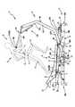
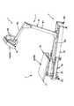
図1で示したように、台状体2を本体3に上下揺動自在に枢支し、保持体4を本体3に前後揺動自在に枢支し且つ使用者Sを前方から当接して保持し、台状体2と保持体4を枢支連結し且つ本体3に揺動自在に枢支されたリンク体5で、台状体2の上下揺動を保持体4の前後揺動に変換して、使用者Sの前傾を規制することで、使用者Sは「骨盤を前に送りながらの重心移動」が出来ると共に、使用者S自身の足の運動軌跡がペダル等によって束縛されることなく、各使用者Sの体格や筋力、関節の可動範囲に応じた自由な動きが可能となる。
尚、足の動きが自由であるからこそ、各使用者Sが実際に走る際のフォーム、つまり、走りの実動作(リアルラン(登録商標))がわかる。これと同時に、使用者Sがより良いフォームを身に着けること(マスターラン(登録商標))の糸口となる。
つまり、使用者Sは、バランス良く空中で、左右の足を素早く切り返すことが可能となり、踏み面2a(地面)に力を伝えるのに適した体幹Tのラインや、股関節K・膝関節H・足首の角度を修得し易くなる。
又、台状体2及び保持体4が枢支されることにより、本体3とは各枢支軸で接触するのみとなり、台状体2及び保持体4と本体3との接触範囲が狭くなって、摩擦によるロスや音を小さく出来る。
更に、保持体4が揺動することに着目すれば、保持体4全体が前方移動した際の反動が、枢支軸回りの円運動により、上下方向へも逃がされて抑制され、運動補助装置1全体が前方へずれ難くすることが可能となる。As shown in FIG. 1, the
In addition, since the movement of the foot is free, the form when each user S actually runs, that is, the actual running operation (real run (registered trademark)) can be known. At the same time, it becomes a clue for the user S to wear a better form (Master Run (registered trademark)).
That is, the user S can quickly turn back the left and right feet in the air in a well-balanced manner, and the trunk T line suitable for transmitting force to the
Further, since the
Further, if attention is paid to the fact that the
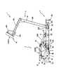
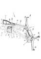
図4で示したように、台状体2を本体3に上下移動自在に支持リンク6を介して連結し、保持体4を本体3に前後直動自在に支持し且つ使用者Sを前方から当接して保持し、台状体2と保持体4を枢支連結したリンク体5で、台状体2の上下移動を保持体4の前後直動に変換して、使用者Sの前傾を規制した場合も同様で、「骨盤を前に送りながらの重心移動」と同時に、使用者Sに応じた自由な足の動きが出来る。
これに加えて、台状体2が支持リンク6を介して本体3に連結しているため、台状体2は、上下方向に沿うだけでなく、上下方向と共に前後方向も含んだ移動(斜めの移動)が可能となり、前傾姿勢Zで使用者Sの踏み込み方向が斜めとなった場合でも、使用者Sは、踏み込み感覚を得やすくなる。As shown in FIG. 4, the
In addition to this, since the
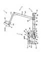
図6のように、台状体2を本体3に上下直動自在に支持し、保持体4を本体3に前後直動自在に支持し且つ使用者Sを前方から当接して保持し、台状体2と保持体4を枢支連結したリンク体5で、台状体2の上下直動を保持体4の前後直動に変換して、使用者Sの前傾を規制した場合も、「骨盤を前に送りながらの重心移動」と、使用者Sに応じた自由な足の動きが同時に出来る。
又、台状体2及び保持体4の両方を、本体3に対して直動自在に(例えば、直線状のローラガイドやレールに沿わす等して)支持しているので、より広い範囲で安定的に、本体3が台状体2や保持体4を支えることが出来る。As shown in FIG. 6, the
In addition, since both the
更に加えて、使用者Sの重心Gの前方移動時に、リンク体5が台状体2の下方移動を保持体4の前方移動に変換して、使用者Sの前傾を規制することで、台状体2の移動方向が重力のかかる方向と同じ向きであると同時に、保持体4の移動方向が使用者Sの重心Gの移動方向と同じ向きであるため、台状体2と保持体4の間の距離が伸び易くなり、この距離の伸びを、主に股関節の伸展で補うことで、更に骨盤が膝上に乗り込む感覚を得ながら、走る実動作を使用者Sにさせることが可能となる。
これと同時に、台状体2を上方に付勢する上方付勢手段7、及び/又は、保持体4を後方に付勢する後方付勢手段8を有することで、付勢手段7、8の付勢力に抗って、使用者Sは、台状体2をより強い力で踏み込むこととなるため、更にトレーニング負荷を上げることも可能となる。
更には、使用者Sは、踏み面2aから逆に反力を得ることとなり、自然と前方に高く足が上がる(足を上げるのではなく上がる)こととなり、リラックスした状態での理想のフォーム(走る動作、歩く動作)を修得し易い。In addition, the link body 5 converts the downward movement of the
At the same time, by having the upper biasing means 7 for biasing the
Furthermore, the user S gets a reaction force from the
そして、保持体4で台状体2を踏む位置Fより前方に重心Gがある使用者Sの体幹Tを保持し、体幹Tを保持された使用者Sの前傾を、本体3に対して台状体2及び/又は保持体4を相対移動させながら規制することで、体幹Tを保持された時の使用者Sの前傾を規制して、骨盤が膝上に乗り込む感覚の取得や、踏む位置Fや使用者Sの可動範囲の違いの許容を実現できる。
尚、本発明における本体3に対する台状体2及び/又は保持体4の相対移動とは、本体3に対して上下方向、前後方向又は斜め方向に沿った移動分のみを有した直動の他、揺動や、リンクを介した移動、曲線状のローラガイドやレール等に沿った移動など、移動する方向、直線状であるか曲線状であるかを問わず、本体3に対する台状体2及び/又は保持体4の位置関係や、本体3から台状体2及び/又は保持体4までの距離が変化していれば良い。
この本体3に対する台状体2及び/又は保持体4の位置関係や距離の変化を、体幹Tの保持体4によって、本来ならば転倒する(台状体2を踏む位置Fより前方に重心Gがある)前傾姿勢Zが維持され且つリラックス状態で両手手放しとなった使用者Sは、主に股関節の伸展で補うことしかなく、骨盤が膝上に乗り込む感覚を得ながら、走る実動作を使用者Sにさせることが可能となる。Then, the trunk T of the user S having the center of gravity G in front of the position F where the holding
The relative movement of the
Changes in the positional relationship and distance of the
尚、本発明に係る運動補助装置は、上述した特徴の他に、前記リンク体5と台状体2及び/又は保持体4との枢支位置を変更して、前記台状体2の上下移動に対する前記保持体4の前後移動の距離の比を変える移動比可変手段7を有していても良い。 In addition to the above-described features, the exercise assisting apparatus according to the present invention changes the pivot position between the link body 5 and the
この他の特徴として、本発明に係る運動補助装置は、使用者Sが踏む台状体2と、この台状体2を下方から支持する本体3と、この本体3の上方に配設された保持体4を有していて、この保持体4で前記台状体2を踏む位置Fより前方に重心Gがある使用者Sの体幹Tを保持する運動補助装置であって、前記体幹Tを保持された使用者Sが台状体2の前記踏む位置Fを踏み込みながら重心Gを前方移動させる時に、前記本体3に対して台状体2を上下移動させて、前記使用者Sの前傾を規制していても良い。 As other features, the exercise assisting device according to the present invention is provided with a
本発明に係る運動補助装置は、使用者Sが踏む台状体2と、この台状体2を下方から支持する本体3と、この本体3の上方に配設された保持体4を有していて、この保持体4で前記台状体2を踏む位置Fより前方に重心Gがある使用者Sの体幹Tを保持する運動補助装置であって、前記体幹Tを保持された使用者Sが台状体2の前記踏む位置Fを踏み込みながら重心Gを前方移動させる時に、前記本体3に対して保持体4を前後移動させて、前記使用者Sの前傾を規制していても良い。 The exercise assisting apparatus according to the present invention includes a
本発明に係る運動補助装置は、前記台状体2は、前記使用者Sの重心Gの前方移動時に下方へ移動されて、前記使用者Sの前傾を規制していても良い。 In the exercise assistance device according to the present invention, the
本発明に係る運動補助装置は、前記保持体4は、前記使用者Sの重心Gの前方移動時に前方へ移動されて、若しくは、前記使用者Sの重心Gの前方移動時に後方へ移動されて、前記使用者Sの前傾を規制していても良い。 In the exercise assisting device according to the present invention, the holding
本発明に係る運動補助装置は、前記使用者Sは、前記台状体2をペダル71を介して踏み、このペダル71は、前記本体3から前上方に延びるレール72に沿って移動自在に取り付けられていても良い。 In the exercise assisting apparatus according to the present invention, the user S steps on the
これらにより、リンク体5と台状体2及び/又は保持体4との枢支位置を変更して、台状体2の上下移動に対する保持体4の前後移動の距離の比を変える移動比可変手段を有した際には、使用者Sの体格だけでなく、保持体4によって支えられる体幹Tの前傾具合を調節でき、競技力向上を目指すアスリートから健康増進を図る年配者まで、使用者Sの希望に応じてトレーニング負荷を変えられる。 By these, the movement ratio variable which changes the ratio of the distance of the back-and-forth movement of the holding
又、上記と同様に、台状体2と本体3と保持体4を有し、保持体4で前傾姿勢Zで保持された使用者Sが重心Gを前方移動させる時に、使用者Sの前傾を規制していると同時に、使用者Sの前傾の規制は、保持体4を前後移動させながら行う際には、踏む位置Fや使用者Sの可動範囲の違いが、保持体4の移動分によって許容され、使用者Sの股関節を確り伸展させることが可能となる。 Similarly to the above, when the user S, which has the
これは、台状体2を上下移動させて、使用者Sの前傾を規制する際にも同様で、踏む位置Fや使用者Sの可動範囲の違いを許容でき、使用者Sは、骨盤が膝上に乗り込む感覚を得られる。
つまり、本体3に対して、台状体2や保持体4を相対的に移動させれば、体幹Tを保持された時の使用者Sの前傾を規制して、骨盤が膝上に乗り込む感覚の取得や、踏む位置Fや使用者Sの可動範囲の違いの許容を実現できる。This is the same when the table 2 is moved up and down to restrict the forward tilt of the user S, and the difference in the stepping position F and the movable range of the user S can be allowed. Can get a sense of getting on the knee.
That is, if the
更に、台状体2を、使用者Sの重心Gの前方移動時に下方へ移動して、使用者Sの前傾を規制する際には、高さ位置が変わらない保持体4から、台状体2が離れることとなり、保持体4と台状体2の間の距離が伸びる。この距離の伸びの分を、主に股関節が伸展して補い、より走る実動作に近い動きを使用者Sにさせることが出来る。
又、台状体2の下方への移動具合によって、硬い床面を蹴る感覚や砂地で走るような感覚を使用者Sに与える等、使用者Sへの負荷を加減することも可能となる。Furthermore, when the
Further, depending on the downward movement of the
これと同様に、使用者Sの重心Gの前方移動時に、保持体4が前方へ移動しながら、使用者Sの前傾を規制する際にも、前後位置が変わらない台状体2から、保持体4が離れて、台状体2と保持体4の間の距離が伸び、この距離の伸びを、主に股関節の伸展で補って、骨盤が膝上に乗り込む感覚を得ながら、走る実動作を使用者Sにさせることが可能となる。
又、この場合における使用者Sの前傾の規制とは、保持体4の前方移動具合に応じて、使用者Sの前傾具合が決まる(制限される)との意である。
これとは逆に、使用者Sの重心Gの前方移動時に、保持体4が後方移動しながら、使用者Sの前傾を規制する際には、使用者Sの重心Gは前方へ移動しながらも、体幹T(上半身)は、逆に、保持体4によって後方へ移動させられることから、より強く股関節の伸展が促される。尚、保持体4の後方移動には、後上方に移動することも含む。Similarly, when the forward movement of the center of gravity G of the user S is performed, the holding
Further, in this case, the restriction on the forward tilt of the user S means that the forward tilt of the user S is determined (restricted) according to the forward movement of the holding
On the contrary, when the forward movement of the gravity center G of the user S is performed, the holding
使用者Sが台状体2をペダル71を介して踏むように構成し、このペダル71を、本体3から前上方に延びるレール72に沿って移動自在に取り付ける際には、使用者Sの足を、ペダル71とレール72によってガイドやサポートしながらも、台状体2を踏み抜くことが出来、使用者Sは、その年代や目的に応じて、踏み抜く感覚や、台状体2からの反力が得られる。 When the user S is configured to step on the
本発明に係る運動補助装置によると、体幹を保持された使用者が重心を前方移動させる時に、本体に対して台状体や保持体を相対的に移動させて、使用者の前傾を規制することで、重心移動を伴った体幹中心の動きを使用者にさせることが可能となり、走る、歩くなどの実動作に限りなく近い動作をすることによって、使用者を問わず、有酸素運動のトレーニング効果の向上が図れる。 According to the exercise assisting device of the present invention, when the user holding the trunk moves the center of gravity forward, the user moves the trapezoidal body and the holding body relative to the main body to thereby tilt the user forward. By regulating, it becomes possible for the user to move the center of the trunk with the movement of the center of gravity, and by performing movements that are as close as possible to actual movements such as running and walking, aerobic regardless of the user The training effect of exercise can be improved.
以下、本発明の実施の形態を図面を参照して説明する。
<第1実施形態>
図1〜3には、本発明の第1実施形態に係る運動補助装置1が示されている。
この運動補助装置1は、使用者Sが踏む台状体2と、台状体2を下方から支持する前後に長い本体3と、本体3の上方に配設された保持体4と、台状体2の上下移動を保持体4の前後移動に変換するリンク体5と、台状体2を上方へ付勢する上方付勢手段7を有している。Hereinafter, embodiments of the present invention will be described with reference to the drawings.
<First Embodiment>
1-3, the exercise assistance apparatus 1 which concerns on 1st Embodiment of this invention is shown.
The exercise assisting device 1 includes a table-
「台状体2」
図1、2に示すように、第1実施形態における台状体2は、前後に長い台フレーム枠20と、この台フレーム枠20の前端部を本体3に揺動自在に枢支する台枢支軸21と、台フレーム枠20上に設けられ且つ踏み面2aを備えた踏み面枠22を有している。
台フレーム枠20は、前後に延びる左右の台フレーム23a、23bと、この左右の台フレーム23a、23bの間を連結する4つの連結材24a、24b、24c、24dと、台フレーム枠20をリンク体5に連結する台連結部25を有している。
左右の台フレーム23a、23bは、中空状の角柱であって、本体3より若干短い前後長さを持つ。各台フレーム23a、23bの断面は、上下に長い矩形状に形成されている。"Trap-shaped
As shown in FIGS. 1 and 2, the
The
The left and right base frames 23 a and 23 b are hollow prisms and have a slightly shorter front and rear length than the
台状体2における4つの連結材24a〜24dは、前から順に、台枢支軸21の直後位置で左右の台フレーム23a、23bを連結する前連結材24aと、左右の台フレーム23a、23bを前後中間位置より後方で連結する前後2本の支持連結材24b、24cと、左右の台フレーム23a、23bの後端部を連結する後連結材24dである。
又、4つの連結材24a〜24dも、中空状の角柱であって、各連結材24a〜24dの長さ、つまり左右の台フレーム23a、23b間の距離は、使用者Sの肩幅と同じか若干広い。
尚、各台フレーム23a、23bの前後中央部と後部には、後述する踏み面枠22の取付部29を取り付けるための受孔が、台フレーム23a、23bの長手方向に沿って複数設けられている。The four connecting
Also, the four connecting
In addition, a plurality of receiving holes for attaching a mounting
前連結材24aの断面も、矩形状に形成されているが、前後が長くなる向きに配置されており、前連結材24aの下面が、左右の台フレーム23a、23bの下面と同じ高さ位置に(面一状に)設けられている。尚、このとき、前連結材24a後面と各台フレーム23a、23b左右内面に亘って、平面視略三角形状の補強板が取り付けられていても良い。
前後2本の支持連結材24b、24cは、左右の台フレーム23a、23bを連結すると共に、上述の台連結部25、及び上方付勢手段7の上端を支持している。The cross section of the front connecting
The two front and rear support connecting members 24b and 24c connect the left and right base frames 23a and 23b, and support the upper ends of the above base connecting portion 25 and the upper biasing means 7.
2本の支持連結材24b、24cは、左右の台フレーム23a、23bを前後中間位置の直後(前連結材24aと後連結材24dの前後中間位置)に設けられた前支持連結材24bと、この前支持連結材24bから後方へ所定距離だけ離れた位置(前支持連結材24bと後連結材24dの前後中間位置)に設けられた後支持連結材24cである。
前後の支持連結材24b、24cの断面も、矩形状に形成だが、前連結材24aとは異なり、上下が長くなる向きに配置されている。
前後の支持連結材24b、24cの下面は、左右の台フレーム23a、23bの下面と同じ高さ位置に設けられている。尚、このとき、前支持連結材24bは前面側に、前支持連結材24bは後面側に、各支持連結材24b、24cと各台フレーム23a、23b左右内面に亘る平面視略三角形状の補強板が取り付けられていても良い。The two support connecting members 24b and 24c include the front support connecting member 24b provided on the left and right base frames 23a and 23b immediately after the front / rear intermediate position (the front / rear intermediate position of the front connecting
The cross sections of the front and rear support connecting members 24b and 24c are also formed in a rectangular shape, but unlike the
The lower surfaces of the front and rear support connecting members 24b and 24c are provided at the same height as the lower surfaces of the left and right base frames 23a and 23b. At this time, the front support connecting member 24b is on the front side, the front support connecting member 24b is on the rear side, and the support connecting members 24b and 24c and the base frames 23a and 23b are substantially triangular in a plan view. A plate may be attached.
台状体2における前後の支持連結材24b、24cの間には、上述した台連結部25が設けられているが、この台連結部25は、前後方向に延びる左右2本の台支持材と、これらの台支持材に挟持された軸支持材と、この軸支持材の下端から後方に延びる上揺動ストッパ材を有している。
左右の台支持材は、中空状の角柱であって、前支持連結材24b後面と後支持連結材24c前面に亘っており、左右対称位置に配設されている。
各台支持材の断面は、上下が長い矩形状となっている。Between the front and rear support connecting members 24b and 24c in the table-
The left and right pedestal support members are hollow prisms, which extend over the rear surface of the front support connection member 24b and the front surface of the rear support connection member 24c, and are arranged at symmetrical positions.
The cross section of each base support member has a rectangular shape with a long top and bottom.
軸支持材も、中空状の角柱で、断面が前後に長い矩形状であって、上下方向(左右の台フレーム23a、23bに直交する向き)に延びている。
この軸支持材の上面は、各台フレーム23a、23b上面や、各支持連結材24b、24c上面、各台支持材の上面と同じ高さ位置にあるが、軸支持材の下端部は、台フレーム枠20から下方へ突出するように設けられている。
この軸支持材の突出方向中途部に、台リンク連結軸52を挿通する筒体が、長手方向を左右に向けて設けられている。The shaft support member is also a hollow prism, has a rectangular shape with a long cross section, and extends in the vertical direction (direction perpendicular to the left and right base frames 23a and 23b).
The upper surface of the shaft support member is at the same height as the upper surfaces of the base frames 23a and 23b, the upper surfaces of the support connecting members 24b and 24c, and the upper surfaces of the base support members. It is provided so as to protrude downward from the
A cylindrical body that passes through the pedestal
上揺動ストッパ部は、中空状の角柱であって、断面が略正方形状に形成されている。
上揺動ストッパ部の上面における前後方向中途部には、略円錐台状の緩衝材26が上方突出状に設けられ、この緩衝材26の上面は、台状体2が所定角度だけ上方揺動した際に、本体3で後述する揺動ストッパ連結材36dの下面に当接する。The upper swing stopper portion is a hollow prism and has a substantially square cross section.
A substantially
緩衝材26は、ゴム等の弾性材の他、スプリングなど衝撃を吸収する素材であれば良い。
緩衝材26の下面から下方へ軸材が延び、この軸材が上揺動ストッパ部を下面まで上下に貫通している。軸材の下端部は、上揺動ストッパ部の下面から下方へ突出しており、この突出部分にナット等の固定具で取り付けることで、緩衝材26を、上揺動ストッパ部に固定する。The
A shaft member extends downward from the lower surface of the
上揺動ストッパ部の後端は、この後端から下方へ突き出た板状の突出部が設けられている。
この突出部の突出距離は、上述したナット等の固定具の上下高さより長く、台状体2が上方揺動して上揺動ストッパ部が、運動補助装置1の設置面に接触しそうになっても、設置面には先に突出部が当たり、緩衝材26の固定具を保護している。The rear end of the upper swing stopper is provided with a plate-like protrusion that protrudes downward from the rear end.
The projecting distance of the projecting portion is longer than the vertical height of the fixture such as the nut described above, and the
尚、このとき、上揺動ストッパ部の上面と軸支持材の後面に亘って、平面視略三角形状の補強板が取り付けられていても良い。
又、左右の台フレーム23a、23bの後端部にも、略円錐台状の緩衝材26が、左右それぞれに下方突出状に設けられており、これらの緩衝材26の下面は、台状体2が所定角度だけ下方揺動した際に、本体3における本体フレーム枠30の上面に当接する。At this time, a substantially triangular reinforcing plate in plan view may be attached over the upper surface of the upper swing stopper portion and the rear surface of the shaft support member.
Further, substantially
台状体2における上述した台枢支軸21は、左右の台フレーム23a、23bの前端部を貫通状に取り付けられており、本体3前部の上面に設けられた台軸受部31で軸承されている。
従って、台状体2は、この台枢支軸21回りに円運動することとなる。ただし、円運動といっても、台状体2の揺動角度が、ごく限られていると同時に、台フレーム枠20の前後長さを、本体3の前後長さに近づけるなど出来るだけ長く設定することで、台状体2の動きを、上下方向に沿った直線的な移動に近似できる。The above-described
Therefore, the
台状体2における上述した踏み面枠22は、前後に延びる左右の面フレーム27、27と、この左右の面フレーム27、27の間を連結する5つの連結材と、これらの面フレーム27、連結材を上から覆う踏み面材28と、踏み面枠22を台フレーム枠20に取り付ける取付部29を有している。
踏み面枠22における左右の各面フレーム27は、上述した台フレーム23a、23bと略同じ幅を持ち且つ前後に長い板材の左右端縁から、同一形状の2枚の板材が左右に並んで上方突出して形成されている。The above-described
The left and right surface frames 27 of the
各面フレーム27の上端辺は、側面視で、前端から所定距離だけ真っ直ぐ後方へ進んだ後、後方へいくほど徐々に高くなる後上り状に形成されている。
尚、各面フレーム27の後端辺は、フレーム後部から真っ直ぐに後上方へ向かうよう形成されている。The upper end side of each
In addition, the rear end side of each
左右の面フレーム27、27間の距離は、上述の台フレーム23a、23b間と略同じで、使用者Sの肩幅と同じか若干広い。
又、各面フレーム27の長さは、使用者Sが走ったときの歩幅より十分大きい長さであり、この各面フレーム27の長さが、上述の踏み面材28の上面部28a(踏み面2a)の前後長さとなる。The distance between the left and right surface frames 27, 27 is substantially the same as that between the above-described
Further, the length of each
踏み面枠22における5つの連結材は、前から順に、左右の面フレーム27、27の上端形状に沿って、略等間隔に設けられている。
5つの連結材も、中空状の角柱で、断面が前後に長い矩形状に形成されている。
各連結材の長さは、左右の台フレーム23a、23b間の距離よりも長く、使用者Sの肩幅や、左右足間よりも十分広い長さとなる。
尚、この連結材の長さが、踏み面材28の上面部28a(踏み面2a)の左右幅となる。The five connecting members in the
The five connecting members are also hollow prisms and are formed in a rectangular shape with a long cross section.
The length of each connecting member is longer than the distance between the left and right base frames 23a and 23b, and is sufficiently longer than the shoulder width of the user S and between the left and right feet.
The length of the connecting material is the left-right width of the
踏み面枠22の踏み面材28は、左右の面フレーム27、27及び5つの連結材に対して上から被せて覆うものである。
踏み面材28は、上面部28aと、前面部と、左右側面部と、後面部を有している。The
The
踏み面材28の上面部28a(つまり、踏み面2a)は、後上り状の各台フレーム23a、23b上端に沿って被さるため、上面部28a前端から所定距離だけ後方へ延びる平坦な部分2bと、この平坦な部分の後端から徐々に高くなる後上り部分2cとを有することとなる。尚、使用者Sは、平坦な部分2bから後上り部分2cへの変わり目を踏む(着地する)と、台状体2(踏み面2a)からの反発を得やすい。
踏み面材28の前面部は、左右の面フレーム27、27の前端を前方から覆うところ、前面部の上下高さが、各面フレーム27の上下高さと、略同一のため、前面部によって、前方向からは各面フレーム27が見えない。
尚、踏み面2aは、表面がラバー等で覆われるなど、滑り止めが施され、使用者Sが足で踏むのに十分に広さを有している。Since the
The front surface portion of the
Note that the
これと同様に、左右の側面部は、左右の面フレーム27、27を左右外方から覆うところ、側面部の形状が、各面フレーム27の形状と、側面視で略同一か、若干後方に長いため、側面部によって、左右外方からは各面フレーム27、各連結材が見えない。
尚、踏み面材28の後面部は、左右の面フレーム27の後上端面だけを後上方方から覆うため、各面フレーム27の後上端面は見えないが、それ以外の範囲を覆わないために、踏み面枠22は、後方開口状に形成されている。Similarly, the left and right side surfaces cover the left and right surface frames 27, 27 from the outside of the left and right sides, and the shape of the side surfaces is substantially the same as the shape of each
In addition, since the rear surface portion of the
踏み面枠22の取付部29は、各台フレーム23a、23bと略同じ幅を持ち且つ前後に細長い板材の左右端縁から、前後細長い2枚の板材がそれぞれ下方突出し、この2枚の板材の間に前記各台フレーム23a、23bが嵌る状態で、台フレーム23a、23bに上方から被さるように形成されている。
取付部29の前後長さは、各面フレーム27及び踏み面材28の前後長さより若干短く、各面フレーム27で前後真っ直ぐに延びる下端辺(詳しくは、面フレーム27の前端やや後方から、面フレーム27後端面が後上り始める地点のやや前方まで)の長さより多少短く形成されている。The
The front and rear lengths of the
この前後に長い取付部29は、少なくとも前端部及び後端部に、それぞれ取付孔が設けられており、この取付孔と、各台フレーム23a、23bの中途部に設けられた複数ある受孔の何れかと挿通させて、取付ネジ等の固定具によって、台フレーム枠20に対して、踏み面枠22を固定する。
尚、取付孔に挿通させる際に、複数の受孔から適宜選択することで、使用者Sの体格や目的に応じて、台フレーム枠20に対する踏み面枠22の前後位置を変更することが出来る。The front and rear
In addition, when making it insert in an attachment hole, the front-back position of the
「本体3」
図1、2に示すように、第1実施形態における本体3は、前後に長い本体フレーム枠30と、この本体フレーム枠30の前端部で台状体2を揺動自在に枢支する台軸受部31と、本体フレーム枠30の前後中途部で保持体4を揺動自在に枢支する保持軸受部32と、本体フレーム枠30の前後中央部でリンク体5を揺動自在に枢支するリンク軸受部33を有している。
本体フレーム枠30は、前後に延びる左右の本体フレーム34a、34bと、この左右の本体フレーム34a、34bの前端及び後端をそれぞれ結ぶ前脚35a、後脚35bと、左右の本体フレーム34a、34bの間を連結する4つの連結材36a、36b、36c、36dを有している。
左右の本体フレーム34a、34bも、中空状の角柱であって、各台フレーム23a、23bよりも、台軸受部31等の分だけ長く形成されている。又、各本体フレーム34a、34bの断面も、上下に長い矩形状に形成されているが、その上下長さ、左右幅共に、各台フレーム23a、23bより大きく形成されている(つまり、台フレーム23a、23bより太い)。"
As shown in FIGS. 1 and 2, the
The
The left and right main body frames 34a and 34b are also hollow prisms, and are longer than the
本体3における前後脚35a、35bについて述べる。
前脚35a及び後脚35bは、中空状の角柱を左右に向けて配置する等して、実動作を行う使用者S及び運動補助装置1を支えるものであれば良いが、例えば、以下のようなものであっても構わない。
まず、前脚35aについて述べると、前脚35aは、本体フレーム34a、34bの左右前端に亘って取り付けた上梁材と、この上梁材の下方に複数の緩衝材を介して取り付けられた下梁材を備えている。The front and
The
First, the
この場合において、上梁材は、各本体フレーム34a、34bと略同じ太さの中空状の角柱を左右に向け、断面が上下に長い矩形状となる向きに配置されている。上梁材の左右長さは、本体フレーム34a、34bの左右外側面間の距離よりも大きく、更に、上述した台状体2における踏み面2aの左右幅よりも大きい。 In this case, the upper beam member is arranged in a direction in which a hollow prism having substantially the same thickness as each of the main body frames 34a and 34b is directed to the left and right, and the cross section is a rectangular shape that is long in the vertical direction. The left and right length of the upper beam material is larger than the distance between the left and right outer surfaces of the main body frames 34a and 34b, and further larger than the left and right width of the
上梁材の下面の左右端部及び中央部には、それぞれ、略円柱状の緩衝材が設けられており、この緩衝材も、台状体2における緩衝材26と同様で、ゴム等の弾性材の他、スプリングなど衝撃を吸収する素材であれば良い。
緩衝材の上下面から上下へそれぞれ軸材が延び、この軸材が、上下梁材の内へ、挿通孔を通って、所定長さ分だけ進入している。A substantially cylindrical cushioning material is provided on each of the left and right end portions and the central portion of the lower surface of the upper beam material, and this cushioning material is also similar to the
Shaft members extend vertically from the upper and lower surfaces of the cushioning material, and the shaft members enter the upper and lower beam members through the insertion holes by a predetermined length.
この軸材の進入によって、下梁材に対する上梁材の平面方向の位置決めが成されている。
又、仮に、台状体2や保持体4から本体3に振動が伝わっても、軸材を上下梁材に進入させているだけであるので、下梁材に対する上梁材の平面方向の位置ズレが許容されて、振動を逃がすことが出来る。
尚、軸材を、上下梁材にネジ等で固定していても良く、その場合は、ゴム等の衝撃を吸収する素材で形成された緩衝材によって、振動を緩和する。By the approach of the shaft member, the upper beam member is positioned in the plane direction with respect to the lower beam member.
Also, even if vibration is transmitted from the
Note that the shaft member may be fixed to the upper and lower beam members with screws or the like. In that case, the vibration is mitigated by a buffer material formed of a material that absorbs an impact such as rubber.
この緩衝材の下方にある下梁材も、中空状の角柱であり、その断面は前後に長い矩形状となっている。下梁材の前後幅は、上梁材の前後幅よりも幅広に形成されており、設置面との接触面積をより大きい。
更に、前脚35aにおける上下梁材の左右長さは、本体フレーム34a、34bの左右外側面間の距離よりも大きく、更に、上述した台状体2における踏み面2aの左右幅よりも大きい。The lower beam material below the cushioning material is also a hollow prism, and its cross section has a long rectangular shape in the front-rear direction. The front and rear widths of the lower beam material are formed wider than the front and rear widths of the upper beam material, and the contact area with the installation surface is larger.
Furthermore, the left and right lengths of the upper and lower beam members in the
このように、前脚35aの前後幅及び左右幅を大きくすることで、運動補助装置1の更なる安定化を図り、台状体2、保持体4を確り支え、台状体2の上で、使用者Sが安定して歩く、走る等の実動作を行うことが出来る。
尚、後脚35bは、本体フレーム34a、34bの左右後端に亘って取り付けた点以外は、上梁材、複数の緩衝材及び下梁材については、同様の構成を備えている。In this way, by increasing the front-rear width and the left-right width of the
The
本体3における4つの連結材36a〜36dは、前から順に、台軸受部31の直後位置に設けられた前連結材36aと、左右の台フレーム23a、23bの前端から略3分の1の位置で且つ前記保持軸受部32の下方に設けられた保持連結材36bと、左右の台フレーム23a、23bの前後略位置で且つ前記リンク軸受部33の下方に設けられたリンク連結材36cと、左右の台フレーム23a、23bの前端から略3分の2の位置で且つ台状体2における上揺動ストッパ部の上方に設けられた揺動ストッパ連結材36dである。
又、4つの連結材36a〜36dも、略中空状の角柱であって、各連結材36a〜36dの長さ、つまり左右の本体フレーム34a、34b間の距離は、左右の台フレーム23a、23b間の距離と略同一で、使用者Sの肩幅と同じか若干広い。
前連結材36aは、断面が上下を高くした矩形状となる向きに配置されており、前連結材36aの上面が、台軸受部31を支える支持板31aの下面に当接して設けられ、前連結材36aで、台軸受部31の支持板31aの後部を支えている。The four connecting members 36a to 36d in the
The four connecting members 36a to 36d are also substantially hollow prisms, and the length of each connecting member 36a to 36d, that is, the distance between the left and right main body frames 34a and 34b is determined by the left and right base frames 23a and 23b. It is almost the same as the distance between them, and is the same as or slightly wider than the shoulder width of the user S.
The front connecting member 36a is arranged in a direction in which the cross section has a rectangular shape with the top and bottom raised, and the upper surface of the front connecting member 36a is provided in contact with the lower surface of the
保持連結材36bは、左右の本体フレーム34a、34bの左右内面だけでなく、左右内面から下面に亘って、各本体フレーム34a、34bに接続できるよう、左右端部が、正面視で略L字状に切り欠かれている。
尚、保持連結材36b前面には、左右の本体フレーム34a、34bの左右内面に亘る補強板が取り付けられていても良く、この場合には、補強板の後面と保持連結材36b上面で、保持軸受部32の軸承部材を支えることとなる。
又、この場合の補強版の下端は、各本体フレーム34a、34bの下面と略同じ高さである。The left and right end portions of the
In addition, a reinforcing plate covering the left and right inner surfaces of the left and right main body frames 34a and 34b may be attached to the front surface of the
In this case, the lower end of the reinforcing plate is substantially the same height as the lower surfaces of the main body frames 34a and 34b.
リンク連結材36cも、保持連結材36bと同様に、左右端部が、正面視で略L字状に切り欠かれており、各本体フレーム34a、34bに対して、縦横2方向から接続可能となり、強度向上を図っている。
リンク連結材36c後面は、補強板も、保持連結材36bと同様に有していても良く、この場合、保持連結材36b後面から、各本体フレーム34a、34bの左右内面に亘って補強板が接続され、この補強板の前面とリンク連結材36c上面で、リンク軸受部33の軸承部材を支えることとなる。
尚、この場合の補強板の中央上部や、リンク連結材36cの中央前部は、上述したリンク体5が揺動する際に、接触しないよう切り欠き(逃げ)が形成されている。Similarly to the
The rear surface of the
In this case, the center upper portion of the reinforcing plate and the center front portion of the
揺動ストッパ連結材36dは、断面が前後に長い矩形状となる向きに配置されており、揺動ストッパ連結材36dの上面が、各本体フレーム34a、34bの上面と同じ高さ位置で面一状となっている。
揺動ストッパ連結材36dの下面は、上揺動ストッパ部の緩衝材26の上面と当接する位置に配備されており、この当接によって、台状体2が所定角度以上に上方へ揺動することを防いでいる。
尚、揺動ストッパ連結材36dの左右中途部には、左右対称位置にそれぞれ、軸部より大径状のヘッドを備えたピンが、後方から前方へ向かって貫通状に保持されている。The swing
The lower surface of the swing
A pin having a head having a diameter larger than that of the shaft portion is held in a penetrating manner from the rear to the front in each of the left and right symmetrical portions of the swing
本体3における本体フレーム枠30後下部には、上方付勢手段7の下端を支持するための支持板が設けられている。この支持板は、各本体フレーム34a、34bの左右内面と、後脚35bにおける上梁材の前面とに亘って、接合されている。
尚、支持板の下面は、左右の本体フレーム34a、34b下面と、後脚35bの上梁材の下面と略面一状になっている。A support plate for supporting the lower end of the upper urging means 7 is provided at the lower rear portion of the
The lower surface of the support plate is substantially flush with the lower surfaces of the left and right body frames 34a and 34b and the lower surface of the upper beam member of the
尚、本体フレーム枠30の後端上部には、台状体2の下方揺動を規制する揺動ストッパ材が設けられていても良い。
この揺動ストッパ材は、例えば、断面が前後に長い矩形状で中空の角材(低い部分)と、この角材の高さが約2倍で断面が略正方形の角材(高い部分)を前後に並べて側面視略L字状(階段状)としたものを、本体フレーム枠30の後脚35bの上梁材の上面に配置される。A swing stopper material that restricts the downward swing of the
For example, this rocking stopper material is a rectangular square hollow section (low part) with a long cross section in the front and back, and a square member (high part) having a square shape with a height approximately doubled and a square section. What is substantially L-shaped (stepped) when viewed from the side is disposed on the upper surface of the upper beam member of the
揺動ストッパ材は、開口している左右外方側をそれぞれ側面板で塞ぎ、この側面板を前下方へ所定距離だけ延ばして、各本体フレーム34a、34bの左右外面を左右外方から被さる。
この被さった部分に形成された前後方向に長い長孔に、ネジ等の固定具を挿通させて、揺動ストッパ材を左右の本体フレーム34a、34bに固定する。The swing stopper member covers the left and right outer sides that are opened with side plates, extends the side plates forward and downward by a predetermined distance, and covers the left and right outer surfaces of the main body frames 34a and 34b from the left and right outer sides.
A fixing tool such as a screw is inserted through a long hole formed in the covered portion in the front-rear direction to fix the swing stopper material to the left and right main body frames 34a and 34b.
この固定具での固定位置を長孔の前寄りにすると、台フレーム枠20後下面の緩衝材26が、揺動ストッパ材のうち低い部分の上面に当接することとなって、台状体2の下方揺動範囲が広くなる。
これとは逆に、固定位置を長孔の後寄りにすると、台フレーム枠20の緩衝材26が、揺動ストッパ材の高い部分の上面に当接し、台状体2の下方揺動範囲が狭まる。
このように、揺動ストッパ材を用いた場合には、使用者Sに応じて、台状体2の揺動範囲を変更できる。
尚、この揺動ストッパ材が許容する揺動範囲が浅い(小さい)場合、使用者Sは、「踏み面2aと踏み込む途中で、底を付く」接地感が得られる(例えば、所定スピードをそのまま維持して走る中間走(中間疾走)のイメージ)。
又、揺動ストッパ材が許容する揺動範囲が深く(大きい)場合、使用者Sは、「踏み面2aを踏んだだけ沈み込み、その分、反力が大きくなる」感覚が得られ、踏み面2aからの反発を得て、足を上げるのではなく上がる(例えば、スピードを徐々に上げる加速走のイメージ)。When the fixing position of the fixing tool is set to the front of the long hole, the cushioning
On the contrary, when the fixing position is set behind the long hole, the cushioning
As described above, when the swing stopper material is used, the swing range of the
In addition, when the swing range permitted by the swing stopper material is shallow (small), the user S can get a feeling of grounding that “bottoms down while stepping on the
In addition, when the swing range allowed by the swing stopper material is deep (large), the user S has a feeling that “the stepping
本体3における台軸受部31は、本体フレーム枠30前部の支持板31a上に固定された左右一対の軸承部材によって、台状体2の台枢支軸21を回動自在に支持している。
尚、台軸受部31は、台状体2上の使用者Sの体重や、実動作での踏込みによる反動を十分に支えられる強度、素材、肉厚等で、台枢支軸21とその軸承部材が形成されている。The
The
又、保持軸受部32は、本体フレーム枠30の前後中途部(前端から略3分の1の位置)にある保持連結材36b上に左右一対の軸承部材が、本体フレーム枠30上面から上方突出状に立設されている。
各軸承部材は、上下方向に長い板材で構成され、この板材の上部は略円弧状に形成されている。この円弧状部分の中心付近に、保持枢支軸41を挿通する孔が設けられ、この孔の径と同じ内径を持つ筒体が、左右外面側に設けられている。
この筒体における外周面の下端から下方に向かってフランジが形成されており、軸承部材の強度を向上させている。
このような左右一対の軸承部材によって、本体フレーム枠30上面よりも高い位置(台状体2の台枢支軸21と略同じ高さ位置)で、保持体4の保持枢支軸41が、回動自在に支持されている。The holding
Each bearing member is made of a plate material that is long in the vertical direction, and the upper portion of the plate material is formed in a substantially arc shape. A hole through which the holding
A flange is formed downward from the lower end of the outer peripheral surface of the cylindrical body to improve the strength of the bearing member.
By such a pair of left and right bearing members, the holding
更に、リンク軸受部33も、保持軸受部32のように、本体フレーム枠30の前後中途部(前端から略3分の2の位置)にあるリンク連結材36c上に左右一対の軸承部材が立設されているが、その立設高さは、本体フレーム枠30上面を若干越える程度である。
各軸承部材は、側面視で略正方形状の板材で構成され、この板材の上部は略円弧状に形成されている。
尚、この円弧状部分の中心付近に、リンク枢支軸51を挿通する孔が設けられ、この孔の径と同じ内径を持つ筒体が、左右外面側に設けられている点や、この筒体における外周面の下端から下方に向かってフランジが形成されており、軸承部材の強度を向上させている点は、保持軸受部32と同様である。
このような左右一対の軸承部材によって、本体フレーム枠30上面よりやや低い位置で、リンク体5のリンク枢支軸51が、回動自在に支持されている。Further, like the
Each bearing member is formed of a substantially square plate material in a side view, and the upper portion of the plate material is formed in a substantially arc shape.
In addition, a hole through which the
By such a pair of left and right bearing members, the
「保持体4」
図1、2に示すように、第1実施形態における保持体4は、前傾する使用者Sの体重がかかっても、胸部に前方から当接して使用者Sを支える当接部分(後述のパッド体44)だけでなく、この当接部分を支持するものや、当接部分を本体3と連結するものも含む。
具体的には、保持体4は、側面視で略C字状形成された保持フレーム40と、この保持フレーム40を本体3に揺動自在に枢支する保持枢支軸41と、この保持枢支軸41後下方で保持フレーム40の後端部に設けられたリンク体5との保持連結部42と、保持フレーム40の上部から更に延長状に設けられた支持部材43と、この支持部材43を介して取り付けられた当接部分であるパッド体44を有している。又、パッド体44は、使用者Sとの当接箇所4a越しに使用者Sの血流の拍動を測定し、測定した拍動を演算部によって心拍数に変換するセンサを取り付けても良い。
尚、第1実施形態では、保持体4における保持連結部42に、移動比可変手段を設けていても良いが、この可変手段は、台状体2側の台連結部25や、リンク体5側に設けられていても、若しくは、設けられていなくても良い。
又、本発明では、第1〜3実施形態のように、使用者Sに当接するパッド体44と、このパッド体44を前後揺動(移動)自在に支持するもの全体で、保持体4を構成する場合に限らず、後述の第4〜8実施形態のように、伸縮自在な支持棒材40Aや移動体81などを介して本体3に取り付けたパッド体も、本体3に対して相対的に移動することから、パッド体自体で、保持体4を構成する場合も含む。"Holding
As shown in FIGS. 1 and 2, the holding
Specifically, the holding
In the first embodiment, the holding
In the present invention, as in the first to third embodiments, the holding
保持フレーム40は、台状体2前部下方の本体フレーム枠30間から前上方に真っ直ぐ延びた保持フレーム下部40aと、この保持フレーム下部40a前端で更に上方へ屈曲し真っ直ぐ延びた保持フレーム中途部40bと、この保持フレーム中途部40bの上端で屈曲し後上方に向けて真っ直ぐ延びた保持フレーム上部40cを有している。尚、保持フレーム40は、下部40a、中途部40b、上部40cに区分されず、一体的に形成されていても良く、その形状も側面視で前方に湾曲した略三日月状等であっても良い。
又、保持フレーム各部40a〜40cは、中空状の部分が互いに連通した角柱であって、断面は前後に長い矩形状に形成されている。The holding
Each of the holding
尚、保持フレーム下部40aは、保持枢支軸41を左右方向に向けて挿通する孔が設けられ、この孔の径と同じ内径を持つ筒体が、保持フレーム下部40aの左右外面側に設けられている。
この筒体における外周面から、保持フレーム下部40aの長手方向に沿って、前上方と後下方に向かって、所定長さのフランジが形成されており、軸承する筒体の強度を向上させている。The holding frame
A flange having a predetermined length is formed from the outer peripheral surface of the cylindrical body toward the front upper side and the rear lower side along the longitudinal direction of the holding frame
尚、後述する位置決め部材を用いる場合には、保持フレーム下部40a上面で保持枢支軸41の直後に、その位置決め部材を固定するためのフランジと、このフランジ内で位置決め部材の上端部に係止する舌片が設けられることとなる。
この場合、保持フレーム下部40aのフランジは、保持フレーム下部40aの上面に沿って、前後に延びる細長い板材と、この板材の左右両端辺から2つ並んで立ち上がった立設片とを有している。この立設片の下端には、位置決め部材の固定用の孔が設けられている。
保持フレーム下部40aの舌片は、フランジの2つの立設片の間で、立設片の長さ方向中途部から前上方へ所定距離延びた後、保持フレーム下部40aの上面と略平行となるよう屈曲して形成されている。When a positioning member to be described later is used, a flange for fixing the positioning member on the upper surface of the holding frame
In this case, the flange of the holding frame
The tongue piece of the holding frame
保持枢支軸41は、保持フレーム下部40aの長手方向中途部を左右貫通状に取り付けられており、本体3の前後中途部の保持連結材36b上面に設けられた保持軸受部32で軸承されている。
従って、保持体4、この保持枢支軸41回りに円運動することとなる。尚、保持体4の円運動も、台状体2の円運動と同様に、保持体4の揺動角度が限られるため、保持体4の動きは、前後方向に沿った直線的な移動に近似できる。
保持体4におけるリンク体5との保持連結部42は、移動比可変手段を兼ねていても良く、この場合の移動比可変手段について、以下に述べる。The holding
Therefore, the
The holding
「移動比可変手段」
移動比可変手段は、リンク体5と保持体4との枢支位置を変更して、台状体2の上下揺動に対する保持体4の前後揺動の距離の比を変える機構である。
移動比可変手段は、保持フレーム下部40aの下端に固定された筒枠と、この筒枠の内部で回動自在に嵌入された略円柱状の回転部材と、この回転部材における回転方向の位置決めをする位置決め部材を有している。"Movement ratio variable means"
The movement ratio variable means is a mechanism that changes the ratio of the distance of the front-rear swing of the holding
The moving ratio variable means includes a cylindrical frame fixed to the lower end of the holding frame
移動比可変手段の筒枠は、軸心方向の厚みが、保持フレーム下部40aの左右幅と略同一であって、略リング状に形成されている。
この筒枠における保持フレーム下部40aの下面に近い部分で、筒枠を径方向に貫通する留め孔が設けられ、この留め孔内に、筒枠の内周面に突き出る芋ネジ等の係合片が出退自在に取り付けられている。
又、筒枠の上部には、位置決め部材で後述する突片が、筒枠を径方向に通す貫通孔も設けられている。The cylinder frame of the movement ratio varying means has a thickness in the axial direction that is substantially the same as the lateral width of the holding frame
A retaining hole that penetrates the tubular frame in the radial direction is provided in a portion of the tubular frame that is close to the lower surface of the holding frame
In addition, a through hole through which a projecting piece, which will be described later with a positioning member, passes through the cylindrical frame in the radial direction is also provided at the upper part of the cylindrical frame.
回転部材は、軸心方向の厚みが、保持フレーム下部40aの左右幅と略同一であり、円盤状に形成されている。
回転部材の下部の外周面には、筒枠の下部の内周面から突出する係合片に対応する係合溝が、厚み方向中央で且つ周方向に沿って設けられている。
従って、回転部材の係合溝が筒枠の係合片と係合することで、左右位置がズレることなく、筒枠内で、回転部材を回転させることが可能となる。The rotating member has a thickness in the axial direction that is substantially the same as the left-right width of the holding frame
On the outer peripheral surface of the lower part of the rotating member, an engaging groove corresponding to the engaging piece protruding from the inner peripheral surface of the lower part of the cylindrical frame is provided at the center in the thickness direction and along the circumferential direction.
Therefore, when the engaging groove of the rotating member is engaged with the engaging piece of the cylindrical frame, it is possible to rotate the rotating member within the cylindrical frame without shifting the left-right position.
更に、回転部材は、その軸心から外れた位置に、保持体4とリンク体5を連結する保持リンク連結軸53を左右方向に向けて通す挿入孔が設けられている。つまり、保持リンク連結軸53は、回転部材の軸心から「偏心」している。
尚、この「偏心」は、回転部材を回転させることによって、保持リンク連結軸53から保持枢支軸41までの距離や、保持リンク連結軸53からリンク枢支軸51までの距離が変わる(つまり、リンク体5と台状体2及び/又は保持体4との枢支位置を変更する)ことを意味する。
その結果、台状体2が、たとえ同じ角度だけ揺動したとしても、保持リンク連結軸53の「偏心具合」によって、この連結軸53から各枢支軸41、51までの距離(保持体4の揺動角度)が変わる、すなわち、台状体2の上下揺動に対する保持体4の前後揺動の距離の比を変わることとなる。Further, the rotation member is provided with an insertion hole through which the holding
This “eccentricity” changes the distance from the holding
As a result, even if the
偏心した保持リンク連結軸53と回転部材における軸心の略反対側の外周面に、3つの係止穴が設けられている。
この3つの係止穴は、回転部材の外周面に、軸心方向(厚み方向)中央で且つ周方向に略等間隔に配置されていて、上述した位置決め部材が係止可能である。Three locking holes are provided on the outer peripheral surface of the eccentric holding
These three locking holes are arranged on the outer peripheral surface of the rotating member in the center in the axial direction (thickness direction) and at substantially equal intervals in the circumferential direction, and the positioning member described above can be locked.
図1において、位置決め部材で選択されているのは、第1係止穴であって、この第1係止穴を選択した場合の台状体2の上下揺動に対する保持体4の前後揺動の距離を100とする。
このとき、筒枠内で回転部材を回転させて、第1係止穴よりも回転部材の周方向に沿って前方にある第2係止穴を選択した場合は、台状体2の上下揺動に対する保持体4の前後揺動の距離は、200となる。
更に筒枠内で回転部材を回転させ、第2係止穴よりも回転部材の周方向に沿って前舌方にある第3係止穴を選択した場合は、台状体2の上下揺動に対する保持体4の前後揺動の距離は、300となる。In FIG. 1, the positioning member is selected as the first locking hole. When the first locking hole is selected, the holding
At this time, when the rotating member is rotated in the cylinder frame and the second locking hole located forward in the circumferential direction of the rotating member is selected rather than the first locking hole, the vertical movement of the
Further, when the rotating member is rotated within the cylinder frame and the third locking hole in the front tongue direction is selected along the circumferential direction of the rotating member rather than the second locking hole, the table-
位置決め部材は、保持フレーム下部40aの上面に沿って配置される長尺ものの部材であって、その全体長さは、回転部材の軸心から保持枢支軸41までの長さより若干短い。
位置決め部材は、細長い板材と、この板材の下端部に設けられた突片と、板材の中途部に設けられた固定筒と、板材の上端部に設けられた係止孔を有している。The positioning member is a long member arranged along the upper surface of the holding frame
The positioning member has an elongated plate material, a projecting piece provided at the lower end portion of the plate material, a fixed cylinder provided in the middle portion of the plate material, and a locking hole provided in the upper end portion of the plate material.
位置決め部材の突片は、筒枠の上部の貫通孔を通って、回転部材の3つの係止穴の何れかに係合する。
この係合によって、回転部材の「偏心具合」が決まり、保持リンク連結軸53から各枢支軸41、51までの距離が変わり、台状体2の上下揺動に対する保持体4の前後揺動の距離の比を変更可能となる。The protruding piece of the positioning member passes through the through hole in the upper part of the cylindrical frame and engages with any of the three locking holes of the rotating member.
By this engagement, the “eccentricity” of the rotating member is determined, the distance from the holding
位置決め部材の固定筒は、板材の下面側の中途部に、その軸心を左右に向けて取り付けられていて、軸心方向の長さは、板材の左右幅と同じである。
固定筒は、位置決め部材の突片を係止孔に係合させた際には、保持フレーム下部40aのフランジの固定用の孔と、挿通する位置にある。
従って、この固定用の孔と固定筒の両方を、ネジ等の固定具を挿通して固定すれ、位置決め部材が、保持フレーム下部40aに固定される。The fixed cylinder of the positioning member is attached to the middle part on the lower surface side of the plate member with its axis directed left and right, and the length in the axial direction is the same as the left and right width of the plate member.
When the protruding piece of the positioning member is engaged with the locking hole, the fixed cylinder is in a position to be inserted into the fixing hole of the flange of the holding frame
Therefore, both the fixing hole and the fixing cylinder are fixed by inserting a fixing tool such as a screw, and the positioning member is fixed to the holding frame
位置決め部材の係止孔は、保持フレーム下部40aの舌片と係止可能な位置にあると同時に、係止孔の左右幅が舌片の左右幅より大きいなど、舌片に対して余裕を持った大きさに形成されている。
従って、係止孔を舌片に係止したまま、係止箇所を中心として位置決め部材全体を上方に揺動させたり、前後方向にずらしたり出来、位置決め部材の突片を、回転部材の係止穴に係止させ易い。
このように、運動補助装置1に移動比可変手段を設けた場合には、使用者Sの好みに応じて、台状体2の上下揺動(移動)に対する保持体4の前後揺動(移動)の距離の比を変えることが出来る。又、移動比可変手段による距離の比の変更が、モータ等の駆動源によって行われても良い。The locking hole of the positioning member is in a position where it can be locked with the tongue piece of the holding frame
Accordingly, the entire positioning member can be swung upward or shifted in the front-rear direction around the locking point while the locking hole is locked to the tongue piece, and the protruding piece of the positioning member can be locked to the rotating member. Easy to lock in the hole.
As described above, when the movement assisting device 1 is provided with the movement ratio variable means, according to the preference of the user S, the holding
図2で特に示したように、保持体4における支持部材43は、保持フレーム上部40cの上端に対して、左右軸回りに揺動自在に設けられた略Y字型のパッド支持部43aと、このパッド支持部43aと保持フレーム上部40cの間に亘る角度調整部43bを有している。
保持体4のパッド支持部43aは、断面略円形のパイプ材2本で略Y字状となるように、左右対称に屈曲させ、その基部を下方から板材で支えるものであって、この板材の前下部が、保持フレーム上部40cの上端に左右軸によって枢支されている。As shown particularly in FIG. 2, the
The
又、このパッド支持部材43aは、使用者Sが台状体2上に乗る際や、前傾姿勢Zをとる際の把持部も兼用する。
つまり、パッド支持部材43aを握った際には、使用者Sがパッド体44を胸部に当てる際に、本来であれば前のめる状態にあっても(つまり、使用者Sの重心Gが台状体2を踏む位置Fより前方にあっても)、使用者Sは、バランスを崩さず前傾姿勢Zをとれる。Further, the
That is, when the user S grips the
保持体4の角度調整部43bは、保持フレーム上部40cに対するパッド体44の角度を調整できるのであれば、何れの機構でも良いが、例えば、角度調整部43bは、パッド支持部43aの略Y字状に分岐する部分と、保持フレーム上部40cの中途部との間に亘って設けられていても良い。この場合、保持フレーム上部40cの中途部との間の距離を、使用者Sの身長、体格等に応じて選択して固定する。
角度調整部43bは、パッド支持部43a側で左右軸に枢支された内筒と、この内筒を挿入可能で且つ保持フレーム上部40c側で左右軸に枢支された外筒と、これら内筒、外筒の位置決めをする固定具を有している。The
The
角度調整部43bの内筒には、長さ方向に沿って複数の調整孔が設けられ、又、外筒の上端部には、固定具を通して固定するための固定孔が設けられている。
従って、複数の調整孔から適宜選択し、パッド支持部43aの保持フレーム上部40cに対する角度で固定することによって、使用者Sの体のサイズや希望する前傾角度α等に応じて、パッド体44の高さ位置・前後位置を変更可能となり、様々な使用者Sに対応できる。The inner cylinder of the
Therefore, the
保持体4におけるパッド体44は、左右幅が使用者Sの両腕間に納まって、使用者Sの胸部に前方から当接可能なシャフト状に形成されており、前傾姿勢Zの使用者Sを保持するものである。
パッド体44は、ゴム等の弾性素材で構成されたり、衝撃を吸収するゲル状の素材などを内部に有していても良く、前傾する使用者Sの体重がかかっても、十分に凹んで使用者S(胸部)を柔軟に支える。
又、パッド体44を略円柱状に形成してもよく、この場合の当接面44a(4a)を、使用者Sの体重がかからずとも、体幹T前面の沿うように左右中央が凹んだ形状としても構わない。The
The
Further, the
尚、パッド体44によって前傾する使用者Sを保持できるのであれば、パッド体44は、胸だけに当接するもの(胸パッド)以外に、腹部から胸部にかけて当接し使用者Sを前方から支えたり、腹部に当接するもの(腹パッド)であっても良く、使用者Sの腕振り等に支障がない範囲で、両腕の付け根を脇から肩上までにかけて前方から支えても良い。
更に、これらを合わせて、腹部から胸部、両肩上にかけてや両脇腹に到るまでを覆って前方から支えるなど、使用者Sが、両手手放しで(つまり、肩甲骨周辺の筋肉が余計な収縮をせず、リラックスした状態で)、本来ならば転倒する前傾姿勢Z(台状体2を踏む位置Fより前方に重心Gがある姿勢)を、使用者Sの体幹Tを保持することによって、維持できるのであれば、何れの形状のパッド体44であっても構わない。In addition, if the user S tilting forward can be held by the
Furthermore, the user S is able to let go of both hands (ie, the muscles around the scapula are contracted excessively, such as supporting them from the front by covering them from the abdomen to the chest, on both shoulders and to the sides of both sides, and supporting from the front. The body T of the user S is held in a forward tilted posture Z (a posture with the center of gravity G in front of the position F on which the stepped
又、パッド体44が使用者Sの両肩、両脇までを覆う場合、その両肩間、両脇間の空間は、使用者Sの体型に応じて変更可能であっても良い。
更に、パッド体44には、使用者Sとの当接箇所44a越しに使用者Sの血流の拍動を測定し、測定した拍動を計数回路にて心拍数に変換するセンサを取り付けていても良い。Further, when the
Further, a sensor for measuring the pulsation of the blood flow of the user S through the
「リンク体5」
図1に示すように、第1実施形態におけるリンク体5は、前後に長手方向を有するよう配備されたリンク枠50と、このリンク枠50の中途部を本体3に揺動自在に枢支するリンク枢支軸51と、リンク枠50の後端を台状体2と連結する台リンク連結軸52と、リンク枠50の前端を保持体4と連結する保持リンク連結軸53を有している。
リンク枠50は、台状体2の上下揺動(移動)を保持体4の前後揺動(移動)に変換するのであれば、何れの構成であっても良いが、例えば、左右一対の細長いリンク板と、左右のリンク板を連結する2つの連結材を有しているものとしても良い。"Link body 5"
As shown in FIG. 1, the link body 5 in the first embodiment pivotally supports a link frame 50 arranged to have a longitudinal direction in the front-rear direction and a middle part of the link frame 50 so as to be swingable on the
The link frame 50 may have any configuration as long as the vertical swing (movement) of the
この場合、リンク体5における左右のリンク板は、それぞれ、前後端が略円弧状に形成され、台状体2で下方突出状に設けられた軸支持材と、保持体4の保持連結部42の両方を、左右外方から挟持する。
リンク板の中途部には、本体3に枢支するリンク枢支軸51を挿通する孔が設けられ、この孔の径と同じ内径を持つ筒体が、左右のリンク板の間に設けられている。
又、2枚のリンク板の左右外面は、本体3におけるリンク軸受部33(左右の軸承部材)で挟持されている。
尚、この筒体は、左右のリンク板を連結するための1つめの連結材を兼用している。In this case, the left and right link plates in the link body 5 are each formed in a substantially arc shape at the front and rear ends, and a shaft support member provided in a downward projecting shape on the
A hole through which the
The left and right outer surfaces of the two link plates are sandwiched between link bearing portions 33 (left and right bearing members) in the
The cylinder also serves as a first connecting member for connecting the left and right link plates.
リンク板の後部には、台状体2と連結する台リンク連結軸52を挿通する挿通孔が設けられている。
尚、移動比可変手段が設けられている場合には、リンク板の前部に、保持体4と連結する保持リンク連結軸53を挿通し且つ長手方向を有する長孔が設けられている。
この場合、リンク板の長孔内を保持リンク連結軸53が摺動することによって、移動比可変手段の回転部材が回転して、保持リンク連結軸53から保持枢支軸41までの距離や、保持リンク連結軸53からリンク枢支軸51までの距離が変わっても、リンク体5と保持体4の相対回動自在な連結状態が維持される。In the rear part of the link plate, there is provided an insertion hole through which the table
In addition, when the movement ratio variable means is provided, a long hole having a longitudinal direction is provided in the front portion of the link plate through the holding
In this case, when the holding
リンク体5における2つの連結材は、上述した筒体と、この筒体の後方で左右のリンク板を連結する後連結材である。
この後連結材は、筒体の後周面から、リンク板材の長手方向に沿って後方へ延びる板材と、この板材に直交する板材の2枚を組み合わせて、側面視で略T字状となるよう構成されている。
この略T字状の後連結材と筒体が、使用者Sの台状体2を踏み抜いた力が、保持体4を前方へ移動させる力に変換される際にも、リンク体5における左右のリンク板を強固に連結している。The two connecting members in the link body 5 are rear connecting members that connect the above-described cylinder and the left and right link plates behind the cylinder.
This rear connecting member is formed in a substantially T shape in a side view by combining a plate member extending rearward along the longitudinal direction of the link plate member and a plate member orthogonal to the plate member from the rear peripheral surface of the cylindrical body. It is configured as follows.
Even when this substantially T-shaped rear connecting member and the cylinder are converted into a force for moving the holding
「上方付勢手段7」
図1、2に示すように、第1実施形態における上方付勢手段7は、使用者Sの台状体2の踏み面2aに対する踏込みに抗って、台状体2を上方へ付勢するものであり、例えば、スプリング、エアシリンダ、オイルシリンダなどで構成される。
上方付勢手段7は、上端が、台状体2前後中央部における後支持連結材24cの後面に支持され、下端が、本体3後部における支持板に支持され、左右一対で且つ左右対称位置に配備されている。
ここで、上方付勢手段7の付勢方向は、支持板から後支持連結材24cに向かって、前上方であり、使用者Sが前傾姿勢Zをとった際の踏み込み方向を十分に受け得る向きに構成されている。
つまり、付勢手段7の付勢力に抗って、使用者Sは、台状体2をより強い力で踏み込むこととなるため、トレーニング負荷を上げることも可能となる。
尚、上方付勢手段7の付勢力は、リンク体5を介して、保持体4を後方揺動させる力として伝わっている。
又、上方付勢手段7として、例えば、エアダンパを用いた場合、使用者Sは、踏み込みに対して、踏み面2aから少し遅れて反発が返ってくる感覚となる。上方付勢手段7として、スプリングを用いた場合、使用者Sは、踏み込みに対する反発・反応が早く、踏み面2aの踏み込み距離(下方移動距離)に比例した反力を、踏み面2aから得ることとなる。"Upward biasing means 7"
As shown in FIGS. 1 and 2, the upward biasing means 7 in the first embodiment biases the
The upper urging means 7 has an upper end supported by the rear surface of the rear support connecting member 24c in the front and rear central portion of the
Here, the urging direction of the upper urging means 7 is the front upper direction from the support plate toward the rear support connecting member 24c, and sufficiently receives the stepping direction when the user S takes the forward tilting posture Z. It is configured in the direction to get.
That is, since the user S steps on the
The urging force of the upper urging means 7 is transmitted as a force that causes the holding
For example, when an air damper is used as the upper urging means 7, the user S feels that the rebound is returned with a slight delay from the
「表示部12」
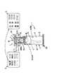
図3中に示すように、第1実施形態における運動補助装置1には、表示部12のメニュー画面として、保持体4の保持フレーム40や支持部材43に、運動補助装置1に乗り方を音やリズム映像で教示したり、保持体使用者Sの体重、性別、年齢等のパーソナルデータ(属性)を入力したり、TV視聴や音楽再生などを制御するコントロール用の筐体11や、その筐体11の表示部12を設けても良い(特に、図3中の左上概略図)。
尚、台状体2における踏み面2aの位置や、保持体4におけるパッド体44の高さなどを電動等で変更可能にするのであれば、図3に示すように、表示部12におけるメニュー画面から、使用者Sの体格、体力等に応じて、台状体2における踏み面2aの前後左右位置や傾斜(負荷調整)、保持体4におけるパッド体44の高さ位置を調整する調整画面に移ることとしても良い(特に、図3中の右上概略図)。“
As shown in FIG. 3, the exercise assisting apparatus 1 according to the first embodiment has a menu screen of the
If the position of the
尚、表示部12は、タッチパネル(タッチボタン)で構成されており、表示部12のタッチボタンを操作することによって、踏み面2aの位置(ベースポジション)や、パッド体44の位置(パッドポジション)、踏み面2aの傾斜や、ジョギング、ランニング、ダッシュ等の実動作の選択や、実動作の時間を入力で調整できる。
入力された使用者Sのパーソナルデータに基づき、使用者Sに適した値(台状体2の踏み面2aの位置や、保持体4のパッド体44の高さ、使用者S自体の前傾角度α、移動速度、移動距離)を計算する演算部が、筐体11に内蔵されている。The
Based on the input personal data of the user S, values suitable for the user S (the position of the
尚、筐体11には、使用者Sのパーソナルデータを記憶したUSBを差し込むUSBポートを備えていても良く、この場合には、USBからパーソナルデータを読み取ったり、演算部で計算したトータル距離や、総消費カロリーなどをUSBに記録しても良い。更に、筐体11に、携帯電話の充電器やドリンクホルダを備えていても良い。 The
「使用態様」
第1実施形態に係る運動補助装置1の使用態様について説明する。
まず、使用者Sは、台状体2の踏み面2a上に立ち、保持体4の支持部材43等を掴みながら、パッド体44の当接面4aに胸をつけて、台状体2を踏む位置Fより重心Gが前方にある前傾姿勢Zをとる。
この前傾姿勢Zの使用者Sは、その体重や希望する負荷等に合わせて適切な負荷となるように、台状体2における踏み面材28の前後位置、保持体4における保持フレーム40に対する支持部材43の角度(パッド体44の高さ)、移動比可変手段を有していれば、この可変手段による台状体2の上下揺動に対する保持体4の前後揺動の距離の比の変更をする。“Usage”
A usage mode of the exercise assisting apparatus 1 according to the first embodiment will be described.
First, the user S stands on the
The user S in the forward tilted posture Z is positioned with respect to the front and back positions of the
又、これらの変更を自動で行う駆動源・機構を有し、表示部12で操作が可能であれば、表示部12におけるタッチパネルで、使用者Sの体重、性別、年齢等の属性を入力し、これらの属性と使用者Sが希望する運動負荷の程度(高負荷から低負荷まで段階的に選択可能)に基づいて、演算部で算出した適切な前傾角度αを表示部12にて通知する。これを見た使用者Sはタッチボタンを操作して、踏み面材28の前後位置、パッド体44の高さ、台状体2の上下揺動と保持体4の前後揺動の距離比を、使用者Sの指示に合わせる。
この前後位置、高さ、距離比の調整は、使用者Sが実際に前傾姿勢Zになった状態で調整することで、使用者Sが前傾具合を確認できる。In addition, if there is a drive source / mechanism for automatically making these changes and the
The adjustment of the front / rear position, height, and distance ratio is performed in a state where the user S is actually in the forward leaning posture Z, so that the user S can confirm the forward leaning degree.
尚、使用者Sが、競技力向上を目指すアスリートならば、前傾角度αもきつめに設定し、股関節Kが硬い(可動範囲が狭い)場合や、高齢者やリハビリを目的とする場合などには、前傾角度αを浅くする。又、表示部12を見たり、タッチボタンの操作は、使用者Sが立位状態でも出来るように、筐体11を首振り状に取り付け、使用者Sの負担を和らげても良い。
このように、自分に応じた前傾姿勢Zをとった使用者Sは、両手手放しであるため、当然に、上述したタッチパネル操作が出来ると共に、肩甲骨周辺の筋肉が、余計な収縮をせず、リラックスした状態となっている。If the user S is an athlete aiming to improve competitiveness, the forward tilt angle α is set tightly, the hip joint K is hard (the movable range is narrow), or the purpose is for the elderly or rehabilitation. For this, the forward tilt angle α is made shallower. Moreover, the
As described above, the user S who has taken the forward tilting posture Z according to his / her own hands can naturally perform the above-described touch panel operation, and the muscles around the scapula do not contract excessively. In a relaxed state.
更に、本来ならば転倒する前傾姿勢Zを、使用者Sが維持できるようになるため、足の踏み込み時に、骨盤が膝上に乗り込む感覚が得やすくなる。
その後、前傾姿勢Zにある使用者Sは、左右交互に膝を上げながら、上げた膝とは反対側の足を振り下ろして、台状体2の踏み面2aを踏む(この時に踏んだ位置が、当初の踏む位置Fとなる)。Furthermore, since the user S can maintain the forward tilting posture Z that would otherwise fall, it becomes easier to obtain a feeling that the pelvis gets on the knee when the foot is stepped on.
Thereafter, the user S in the forward leaning posture Z swings down the foot on the side opposite to the raised knee while stepping up the knee alternately, and steps on the
この踏み込みにつれて、台状体2が沈み込む(下方に揺動)と同時に、保持体4が前方揺動することで、台状体2から保持体4が離れることとなり、台状体2と保持体4の間の距離が伸びる。
この時、使用者Sの上半身(体幹T)は、保持体4によって前傾が規制され、更に、使用者Sが足で踏む位置Fは、当初と変わらないため、使用者Sの身体において、前後移動自在な部位は、骨盤周辺だけとなる。As the stepped-in step, the
At this time, the upper body (trunk T) of the user S is restricted from being tilted forward by the holding
従って、保持体4から台状体2までの距離が伸びた分を、骨盤周辺の動き、つまり、股関節Kの伸展で主に補うしかなく、使用者Sが当初と同じ踏む位置Fで台状体2を踏み込みながら、使用者S(体幹T)を前傾させて重心Gを前方へ移動させることになり、使用者Sの重心Gの前方移動が、主に股関節Kの伸展によって(若しくは、股関節Kの伸展と膝関節Hの伸展が連動して)行われることとなり、体幹Tの前傾による重心Gの前方移動よりも、股関節Kの伸展による重心Gの移動の方が多くなる。
よって、使用者Sの股関節を確り伸展させつつ、いずれの使用者Sにも、走る、歩くなどの実動作に限りなく近い動作が可能となり、所謂、腰が入った状態(「骨盤を前に送りながらの重心移動」)を可能とする。
更には、股関節K周辺の大筋群や、股関節Kから膝関節Hにかけての大腿部の筋群を、主に使うこととなり、大筋群の筋収縮による有酸素運動のトレーニング効果が向上できる。Therefore, the distance from the holding
Therefore, while the user's S hip joint is firmly extended, any user S can perform an operation that is as close as possible to an actual operation such as running or walking. "Move the center of gravity while feeding").
Furthermore, the large muscle group around the hip joint K and the thigh muscle group from the hip joint K to the knee joint H are mainly used, and the training effect of the aerobic exercise by the muscle contraction of the large muscle group can be improved.
これに加えて、従来の車軸移動式自転車エルゴメータとは違って、確りした土台で且つ踏み面2aをもつ台状体2を拇指球で踏み抜くため、実動作に限りなく近い、台状体2から反力を受けながら前へ進む感触を得ることが可能となる。
つまり、使用者Sは、自身の足の運動軌跡がペダル等によって束縛されることなく、各使用者Sの体格や筋力、関節の可動範囲に応じた自由な動きと「骨盤を前に送りながらの重心移動」が同時に出来る。
足の動きが自由であるからこそ、各使用者Sが実際に走る際のフォーム、つまり、走りの実動作(リアルラン(登録商標))がわかる。これと同時に、使用者Sがより良いフォームを身に着けること(マスターラン(登録商標))の糸口となる。
つまり、使用者Sは、バランス良く空中で、左右の足を素早く切り返すことが可能となり、踏み面2a(地面)に力を伝えるのに適した体幹Tのラインや、股関節K・膝関節H・足首の角度を修得し易くなる。
これと同時に、使用者Sは、正しく踏み面2aに力を伝えることにより、踏み面2aから逆に反力を得られ、自然と前方に高く足が上がる(足を上げるのではなく上がる)ことから、リラックスした状態での理想のフォーム(走る動作、歩く動作)を修得し易い。In addition to this, unlike the conventional axle-moving bicycle ergometer, the
That is, the user S can freely move according to the physique and muscle strength of each user S, and the movable range of the joint without restraining the motion trajectory of his / her foot by a pedal or the like. Can move at the same time.
Because the movement of the foot is free, the form when each user S actually runs, that is, the actual running motion (Real Run (registered trademark)) can be known. At the same time, it becomes a clue for the user S to wear a better form (Master Run (registered trademark)).
That is, the user S can quickly turn back the left and right feet in the air in a well-balanced manner, and the trunk T line suitable for transmitting force to the
At the same time, the user S can obtain a reaction force from the
又、台状体2及び保持体4が枢支されることにより、本体3とは各枢支軸で接触するのみとなり、台状体2及び保持体4と本体3との接触範囲が狭くなって、摩擦によるロスや音を小さく出来る。
更に、保持体4が揺動することに着目すれば、保持体4全体が前方移動した際の反動が、枢支軸回りの円運動により、前後方向へ逃がされて抑制され、運動補助装置1全体が前方へずれ難くすることが可能となる。Further, since the
Further, if attention is paid to the swinging of the holding
尚、台状体2における踏む位置Fが前後したり、使用者Sごとの股関節Kの可動範囲が違うということも有り得るが、台状体2が上下揺動したり、保持体4が前後揺動する分によって許容される。
更に、台状体2の下方への揺動具合によって、硬い床面を蹴る感覚や砂地で走るような感覚を使用者Sに与えるなど、使用者Sにかかる負荷を加減しても良い。Although the stepping position F on the
Furthermore, the load applied to the user S may be moderated by giving the user S the feeling of kicking a hard floor or running on sand, depending on how the
尚、左右いずれかの足の踏み込みが終われば、使用者Sは、反対側の足で台状体2を踏み込むが、反対側の足への切り替わりの間に、台状体2は、元の上下位置に戻る。
このような踏み込みを、トレーニング時の使用者Sは、左右リズムよく適切なサイクル繰り返すこととなる。
又、トレーニング中は、保持体4に設けられたセンサによる心拍数等の各種情報をリアルタイムで監視・表示すると共に、これらの情報は演算部のメモリに格納される。Note that when the stepping on one of the left and right feet is finished, the user S steps on the
The user S at the time of training repeats such an appropriate cycle with a good left-right rhythm.
During training, various information such as a heart rate by a sensor provided on the holding
トレーニング終了後には、表示部12には、消費カロリー等のトレーニング結果が表示される。
上述では、左右いずれかの足で踏み込むこととしたが、左右両方の足で、同時に踏み込むことも出来る。After the end of training, the
In the above description, the foot is depressed with either the left or right foot, but the foot can be depressed simultaneously with both the left and right feet.
<第2実施形態>
図4、5には、本発明の第2実施形態に係る運動補助装置1が示されている。
この第2実施形態において第1実施形態と最も異なるのは、台状体2が、枢支されるのではなく、本体3に対して支持リンク6を介して上下移動自在に連結される点と共に、保持体4も、枢支されるのではなく、本体3に対してローラガイドによって、前後直動自在に支持されている点である。Second Embodiment
4 and 5 show an exercise assisting apparatus 1 according to the second embodiment of the present invention.
In this second embodiment, the most different point from the first embodiment is that the
第2実施形態の特徴である支持リンク6は、左右の前支持リンク6a、6aと、左右の後支持リンク6b、6bを有していて、左右それぞれの前後支持リンク6a、6bは、上端が台状体2に枢支連結され、下端が本体3に枢支連結されている。
更に、前支持リンク6aと後支持リンク6bの長さが略等しく、前後支持リンク6a、6bの上端間の距離と下端間の距離も略等しいため、前後支持リンク6a、6bと、台状体2、本体3とが、側面視で、略平行四辺形状に構成されている。The
Further, since the lengths of the
このように平行四辺形状に構成することで、従って、台状体2は、本体3に対して、上面(踏み面2a)の角度を保ったまま、前後支持リンク6a、6b下端を枢支した軸回りに揺動する。
従って、図4にて示したように、前後支持リンク6a、6bの角度が水平から45度未満の範囲では、上下方向に沿った移動分の方が多くなり、又、前後支持リンク6a、6bの揺動角度が小さければ、台状体2は、後下方へ斜めに移動することに近似される。Thus, by configuring the parallelogram shape, the
Therefore, as shown in FIG. 4, when the angle of the front and
つまり、第2実施形態では、台状体2が、上下方向と共に前後方向も含んだ移動(斜めの移動)が可能となり、前傾姿勢Zで使用者Sの踏み込み方向が斜めとなった場合でも、使用者Sは、踏み込み感覚を得やすくなる。
更に、2本の支持リンク6を用いた場合には、台状体2の踏み面2aの角度を保ったまま、斜めの移動が実現される。That is, in the second embodiment, the
Further, when two
尚、台状体2には、踏み面2aの前傾角度を調節する角度変更手段2Aが設けられており、使用者Sに応じて、踏み込み易い角度を選択できる(図7の踏み面2a参照)。
又、台状体2の側面には、上方揺動角度を所定の値(例えば、45度未満)に抑えるストッパが設けられている。The
In addition, a stopper that suppresses the upward swing angle to a predetermined value (for example, less than 45 degrees) is provided on the side surface of the
第2実施形態における本体3には、本体フレーム枠30の左右内面の前部と中途部に、直線状のローラガイド30Cが、本体フレーム枠30の長手方向に沿って、左右一対にそれぞれ設けられている。このローラガイド30Cと、保持体4の保持フレーム下部40aに設けたローラ40Bが係合する。
又、本体フレーム枠30の前内面から後方突出状に、略円錐台状の緩衝材30Dが設けられており、この緩衝材30D先端の後面が、保持体4が前方移動(前方直動)した際に、保持フレーム40下部40a前面に当接可能に配置されている。In the
Further, a substantially
更に、本体フレーム枠30における前支持リンク6aの枢支連結位置下方でも、左右の本体フレーム34a、34bを連結する連結材上に、前方突出状に緩衝材30Dが設けられている。
この緩衝材30Dの先端の後面は、保持体4が後方移動(後方直動)した際に、保持フレーム40下部40aの後面に当接可能に配置されている。Further, a
The rear surface of the tip of the
第2実施形態における保持体4は、その保持フレーム下部40a前部と後部の左右外面に、それぞれローラ40Bが設けられており、このローラ40Bが、上述した前後のローラガイド30Cに係合することによって、本体フレーム枠30内の前部から中途部にかけて、前後直動自在に配備されている。
尚、保持体4が前後直動自在であるならば、ローラガイド30Cとローラ40Bではなく、直線状のレールに沿って前後移動する機構であっても良い。The holding
As long as the holding
又、保持体4は、保持フレーム中途部40bに対して、保持フレーム上部40cが角度選択自在に固定可能であり、保持フレーム上部40c上端に対して、パッド体44が左右軸回りに上下揺動自在に取り付けられている。
尚、パッド体44は、下方揺動する方向に、バネ等の付勢手段44bで付勢されており、使用者Sの前傾具合に応じて、パッド体44が使用者Sの前傾に抗いながら、前方揺動自在に構成されている。又、パッド体44の前面側には、左右一対の把持部43Aが設けられている。Further, the holding
The
第2実施形態におけるリンク体5は、左右一対のリンク板によって構成され、それらの上端が台状体2の台フレーム枠20内に枢支連結され、下端が保持体4の保持フレーム下部40aの後端に枢支連結されている。
従って、このリンク体5によって、台状体2の下方移動が、保持体4(保持フレーム下部40a)の前後直動に変換され、使用者Sは、踏み込むと同時に体幹Tを支えている保持体4が前方移動するため、「骨盤を前に送りながらの重心移動」する感覚を得やすくなる。The link body 5 in the second embodiment is composed of a pair of left and right link plates, the upper ends of which are pivotally connected to the
Therefore, the link body 5 converts the downward movement of the
第2実施形態と第1実施形態におけるもう1つの大きな相違点は、上方付勢手段7ではなく、保持体4を後方に付勢する後方付勢手段8を有している点である。
図4で示されたように、後方付勢手段8は、ゴムチューブ等のように環状の弾性素材であって、後方付勢手段8の前端は、保持体4の保持フレーム下部40a後端部における前掛止材8aに掛け渡され、下端は、本体3の本体フレーム枠30後下部で、左右の本体フレーム34a、34bを連結する後掛止材8bに掛け渡されている。Another major difference between the second embodiment and the first embodiment is that not the upper biasing means 7 but the rear biasing means 8 that biases the holding
As shown in FIG. 4, the rear biasing means 8 is an annular elastic material such as a rubber tube, and the front end of the rear biasing means 8 is the rear end of the holding frame
従って、保持体4が前方直動した際には、この後方付勢手段8が引き伸ばされ、保持体4に対して後方へ引き戻す方向に付勢力が働く。
このように、後方付勢手段8によって保持体4に対して付勢力をかけることで、付勢手段8の付勢力に抗って、使用者Sは、台状体2をより強い力で踏み込むこととなるため、トレーニング負荷を向上できると共に、台状体2下方にあったスペースを有効に活用でき、運動補助装置1全体のコンパクト化が測れる。
尚、この付勢力は、リンク体5を介して、台状体2を上方に付勢する力として伝わっている。
その他の運動補助装置1の構成、作用効果及び使用態様は、第1実施形態と同様である。Therefore, when the holding
Thus, by applying a biasing force to the holding
This urging force is transmitted through the link body 5 as a force that urges the
Other configurations, operational effects, and usage modes of the exercise assistance device 1 are the same as those in the first embodiment.
<第3実施形態>
図6、7には、本発明の第3実施形態に係る運動補助装置1が示されている。
この第3実施形態が、第1、2実施形態と異なるのは、台状体2と保持体4の両方が、本体3に対してローラガイドによって、直動自在に支持されている点である。<Third Embodiment>
6 and 7 show an exercise assisting apparatus 1 according to a third embodiment of the present invention.
The third embodiment is different from the first and second embodiments in that both the
第3実施形態における台状体2は、その台フレーム枠20における前後方向中途部の左右外面と、後面に、それぞれローラ20Aが設けられている。
一方、第3実施形態における本体3には、このローラ20Aと係合する直線状のローラガイド30Cが、長手方向を上下にして、本体3に3つ設けられている。
3つのローラガイド30Cのうち、2つは、本体フレーム枠30左右内面の後部に左右一対に配置され、残り1つは、本体フレーム枠30の後内面に配置されている。The table-
On the other hand, in the
Of the three roller guides 30 </ b> C, two are arranged in a pair on the left and right inner surfaces of the
従って、本体3の3つのローラガイド30Cに係合することによって、台状体2は、本体3に対して上下直動自在に配備されている。
すなわち、台状体2及び保持体4の両方を、本体3に対して、例えば、直線状のローラガイドやレールに沿わす等して支持すれば、より広い範囲で安定的に、本体3が台状体2や保持体4を支えることが出来る。Accordingly, by engaging with the three roller guides 30 </ b> C of the
That is, if both the
尚、台状体2が上下直動自在であるならば、ローラ20Aとローラガイド30Cではなく、直線状のレールに沿って前後移動する機構であっても良い。
図7は、第3実施形態において、台状体2の踏み面2a(28a)を、角度変更手段2Aによって、前傾させたものである。
又、図7では、本体フレーム枠30後部に、台状体2の下方移動位置を調節する台補助具2Bが設けられている。
その他の運動補助装置1の構成、作用効果及び使用態様は、第1、2実施形態と同様である。In addition, as long as the base-
FIG. 7 shows the
In FIG. 7, a table
Other configurations, operational effects, and usage modes of the exercise assistance device 1 are the same as those in the first and second embodiments.
<第4実施形態>
図8には、本発明の第4実施形態に係る運動補助装置1が示されている。
この運動補助装置1は、使用者Sが踏む台状体2と、台状体2を下方から支持する前後に長い本体3と、本体3の上方に配設された保持体4を有している。<Fourth embodiment>
FIG. 8 shows an exercise assisting apparatus 1 according to the fourth embodiment of the present invention.
This exercise assisting device 1 includes a
台状体2は、細長い本体3の後部に跨るように嵌合した溝が底部に形成された略直方体状であって、本体3に対して上下移動自在に取り付けられている。
又、本発明における台状体2の上下移動とは、台状体2全体が上方や下方に移動することを意味する。尚、これ以外にも、台状体2の上面が前に傾く(つまり、上面の前部だけが下方に移動する)ことや、上面が左に傾く又は右に傾く(つまり、上面の左右一方だけが下方に移動する)ことも含む。The
Further, the vertical movement of the
台状体2の上面には、使用者Sが左右の足で踏み込む踏み面2aが設けられており、この踏み面2aは、表面がラバー等で覆われるなど、滑り止めが施されている。
踏み面2aは、使用者Sが足で踏むのに十分に広さを有し、使用者Sが踏み易いように、台状体2上面の左右各端部にそれぞれ設けられている。
尚、踏み面2a自体が、台状体2の上面に対して、角度調整自在に取り付けられていても良く、これによって、使用者Sは、踏み込み時に、足裏と踏み面2aを正対させ易くなり、拇指球で踏み抜いて台状体2からの反力を確り受けることが出来る。
又、台状体2が、使用者Sの左右の足ごとに、それぞれ別体で設けられていても良く、この場合には、使用者Sの足における左右ごとの動きに応じて、左右の台状体2を個々に上下移動させることが出来る。On the upper surface of the
The
Note that the
Further, the
本体3は、上述の台状体2や保持体4を下方から支えながら、床のような設置面に載置されるものである。尚、本体3は、低重心に構成したり、所定重量をもたせて安定感ある構成とすることが好ましい。
本体3は、上述したように、前後方向に細長く形成された胴部30Aと、この胴部30Aの前部に設けられた左右一対の前脚35a、35aと、胴部30Aの後部に設けられた左右一対の後脚35b、35bと、胴部30Aの前部上に立設された起立部30Bを有している。
又、本体3は、胴部30Aの後部上面で台状体2を、上下方向に移動自在となるように下方から支持している。The
As described above, the
Further, the
左右の前脚35a、35aは、本体3の胴部30Aにおける前端部の左右角から、それぞれが左右斜め前外方へ延設されている。各前脚35a、35aの先端下面には、高さ調整自在なアジャストねじ35Cが設けられている。
又、左右の後脚35b、35bは、本体3の胴部30Aにおける後端部の左右角から、それぞれが左右斜め後外方へ延設されており、各後脚35b、35bの先端下面には、首振り自在にキャスタ35D(脚車)が取り付けられている。The left and right
The left and right
尚、このキャスタ35Dは、使用者Sの運動時には、ストッパによって首振りや転がりが防止できる。
又、運動補助装置1を運搬する際には、ストッパを外して後脚35b、35bのキャスタ35Dを首振り可能及び転がり可能とし、前脚35a、35aを持ち上げることで、運搬容易化が図られている。The
Further, when transporting the exercise assisting device 1, the
起立部30Bは、本体3の胴部30A前端部における上面の左右中央から、前斜め上方に延設されており、上方に延びるにつれて前後厚が薄くなるように形成されている。
起立部30Bの延設方向中途部の後面からは、支持棒材40Aが後上方へ延設されており、この支持棒材40Aの先端には上述の保持体4が取り付けられている。尚、支持棒材40Aが伸縮自在に構成されている。The standing
A
尚、支持棒材40A基端部の取付位置は、使用者Sの身長に合わせて、高さ調整自在としても良い。
起立部30Bの上部は、支持棒材40A基端部の取付位置の上方で、二股に分かれた後に合流し、この合流部分は平板状のプレート部11を形成されている。このプレート部11の使用者S側の面には表示部12が設けられており、この表示部12は、タッチパネル(タッチボタン)で構成されている。The mounting position of the base end portion of the
The upper part of the
この表示部12には、使用者Sの体重、性別、年齢等の属性を入力することが可能となっており、又、これらの属性に基づき、使用者Sに適した値(台状体2における上下移動距離、移動速度及び負荷や、保持体4における前後移動距離、移動速度及び負荷、使用者S自体の前傾角度α)を計算する演算部が、本体3(例えば、プレート部11)に内蔵されている。
更には、表示部12のタッチボタンを操作することによって、台状体2や保持体4の移動距離や、使用者Sの前傾角度αを変更することが出来る。The
Furthermore, the movement distance of the
保持体4は、左右幅が使用者Sの両腕間に納まって、使用者Sの胸部に前方から当接可能な略矩形状の当接面4aを有した胸当て様のパッド体で、前傾姿勢Zの使用者Sを保持するものである。
保持体4の当接面4aは、内部にクッション体が詰められており、前傾する使用者Sの体重がかかっても、十分に凹んで使用者S(胸部)を柔軟に支える。又、柔軟に使用者Sを支えるためのスプリング等の付勢手段を、支持棒材40Aに内蔵させても良い。The holding
The
尚、保持体4によって前傾する使用者Sを保持できるのであれば、保持体4は、胸だけに当接するもの以外に、腹部から胸部にかけて当接し使用者Sを前方から支えたり、使用者Sの腕振り等に支障がない範囲で、両腕の付け根を脇から肩上までにかけて前方から支えても良い。(尚、後述のように天井や壁面から保持体4を設ける場合には、後方から使用者Sの体幹Tの前面に回りこんで支えるものであっても良い。)
更に、これらを合わせて、腹部から胸部、両肩上にかけてや両脇腹に到るまでを覆って前方から支えるなど、使用者Sが、両手手放しで(つまり、肩甲骨周辺の筋肉が余計な収縮をせず、リラックスした状態で)、本来ならば転倒する前傾姿勢Z(台状体2を踏む位置Fより前方に重心Gがある姿勢)を、使用者Sの体幹Tを保持することによって、維持できるのであれば、何れの形状の保持体4であっても構わない。If the user S tilted forward can be held by the holding
Furthermore, the user S is able to release both hands (ie, the muscles around the scapula are contracted excessively, such as supporting them from the front by covering them from the abdomen to the chest, over both shoulders and to the sides of both sides, and supporting from the front. The body T of the user S is held in a forward tilted posture Z (a posture with the center of gravity G in front of the position F on which the stepped
又、保持体4が使用者Sの両肩、両脇までを覆う場合、その両肩間、両脇間の空間は、使用者Sの体型に応じて変更可能であっても良い。
更に、保持体4には、当接面4a越しに使用者Sの血流の拍動を測定し、測定した拍動を計数回路にて心拍数に変換するセンサを取り付けていても良い。Further, when the holding
Further, the
又、保持体4裏面(前面)の左右両縁部には、それぞれ前下方に延びる把持部43Aが設けられている。
この把持部43Aを握ることによって、使用者Sが保持体4を胸部に当てる際に、本来であれば前のめる状態にあっても(つまり、使用者Sの重心Gが台状体2を踏む位置Fより前方にあっても)、使用者Sは、バランスを崩さず前傾姿勢Zをとれる。In addition, on both left and right edges of the back surface (front surface) of the holding
By grasping the gripping
尚、保持体4は、上述したように、本体3から延設された伸縮自在の支持棒材40Aの先端(上端)に取り付けられていることから、保持体4は、本体3の上方で前後移動自在に配備されている。
ここで、本発明における保持体4の前後移動とは、保持体4全体が前後方向に沿った移動分を含むことは、勿論、支持棒材40Aの延設方向に沿って、後上方に移動したり、前下方に移動したりすることも含む。Since the holding
Here, the back-and-forth movement of the holding
第4実施形態に係る運動補助装置1の使用態様について説明する。
まず、使用者Sは、台状体2の踏み面2a上に立ち、保持体4の把持部43Aを掴みながら、当接面4aに胸をつけて、台状体2を踏む位置Fより重心Gが前方にある前傾姿勢Zをとる。
この前傾姿勢Zの使用者Sは、その体重や希望する負荷等に合わせて適切な負荷となるように、表示部12におけるタッチパネルで、使用者Sの体重、性別、年齢等の属性を入力する。
これらの属性と使用者Sが希望する運動負荷の程度(高負荷から低負荷まで段階的に選択可能)に基づいて、演算部で算出した適切な前傾角度αを表示部12にて通知する。これを見た使用者Sはタッチボタンを操作して、支持棒材40Aのスタート時の長さを調節して、前傾姿勢Zの前傾角度αを、使用者Sの指示に合わせる。A usage mode of the exercise assisting apparatus 1 according to the fourth embodiment will be described.
First, the user S stands on the
The user S in the forward leaning posture Z inputs attributes such as the weight, sex, age, etc. of the user S on the touch panel in the
Based on these attributes and the degree of exercise load desired by the user S (selectable stepwise from high load to low load), the
この前傾角度αの調整は、使用者Sが実際に前傾姿勢Zになった状態で調整することで、使用者Sが前傾具合を確認できる。
尚、使用者Sが、競技力向上を目指すアスリートならば、前傾角度αもきつめに設定し、股関節Kが硬い(可動範囲が狭い)場合や、高齢者やリハビリを目的とする場合などには、前傾角度αを浅くする。又、表示部12を見たり、タッチボタンの操作は、使用者Sが立位状態でも出来るように、表示部12、プレート部11が、起立部30Bに対して、首振り状に取り付け、使用者Sの負担を和らげても良い(後述の第6実施形態を参照)。The forward tilt angle α is adjusted in a state where the user S is actually in the forward tilted posture Z, so that the user S can confirm the forward tilt state.
If the user S is an athlete aiming to improve competitiveness, the forward tilt angle α is set tightly, the hip joint K is hard (the movable range is narrow), or the purpose is for the elderly or rehabilitation. For this, the forward tilt angle α is made shallower. In addition, the
このように、自分に応じた前傾姿勢Zをとった使用者Sは、両手手放しであるため、当然に、上述したタッチパネル操作が出来ると共に、肩甲骨周辺の筋肉が、余計な収縮をせず、リラックスした状態となっている。
更に、本来ならば転倒する前傾姿勢Zを、使用者Sが維持できるようになるため、足の踏み込み時に、骨盤が膝上に乗り込む感覚が得やすくなる。As described above, the user S who has taken the forward tilting posture Z according to his / her own hands can naturally perform the above-described touch panel operation, and the muscles around the scapula do not contract excessively. In a relaxed state.
Furthermore, since the user S can maintain the forward tilting posture Z that would otherwise fall, it becomes easier to obtain a feeling that the pelvis gets on the knee when the foot is stepped on.
その後、前傾姿勢Zにある使用者Sは、左右交互に膝を上げながら、上げた膝とは反対側の足を振り下ろして、台状体2の踏み面2aを踏む(この時に踏んだ位置が、当初の踏む位置Fとなる)。
この踏み込みにつれて、台状体2が沈み込む(下方に移動させる)ことで、保持体4から台状体2が離れることとなり、保持体4と台状体2の間の距離が伸びる。Thereafter, the user S in the forward leaning posture Z swings down the foot on the side opposite to the raised knee while stepping up the knee alternately, and steps on the
As the stepped-in step, the
この時、使用者Sの上半身(体幹T)は、保持体4によって前傾が規制され、更に、使用者Sが足で踏む位置Fは、当初と変わらないため、使用者Sの身体において、前後移動可能な部位は、骨盤周辺だけとなる。
従って、保持体4から台状体2までの距離が伸びた分を、骨盤周辺の動き、つまり、股関節Kの伸展で主に補うしかなく、使用者Sが当初と同じ踏む位置Fで台状体2を踏み込みながら、使用者S(体幹T)を前傾させて重心Gを前方へ移動させることになり、使用者Sの重心Gの前方移動が、主に股関節Kの伸展によって(若しくは、股関節Kの伸展と膝関節Hの伸展が連動して)行われることとなり、体幹Tの前傾による重心Gの前方移動よりも、股関節Kの伸展による重心Gの移動の方が多くなる。
従って、使用者Sの股関節を確り伸展させつつ、いずれの使用者Sにも、走る、歩くなどの実動作に限りなく近い動作が可能となり、所謂、腰が入った状態(「骨盤を前に送りながらの重心移動」)を可能とする。
更には、股関節K周辺の大筋群や、股関節Kから膝関節Hにかけての大腿部の筋群を、主に使うこととなり、大筋群の筋収縮による有酸素運動のトレーニング効果が向上できる。At this time, the upper body (trunk T) of the user S is restricted from being tilted forward by the holding
Therefore, the distance from the holding
Accordingly, while allowing the user's S 'hip joint to extend securely, any user's S can perform movements that are as close as possible to actual movements such as running and walking. "Move the center of gravity while feeding").
Furthermore, the large muscle group around the hip joint K and the thigh muscle group from the hip joint K to the knee joint H are mainly used, and the training effect of the aerobic exercise by the muscle contraction of the large muscle group can be improved.
これに加えて、従来の車軸移動式自転車エルゴメータとは違って、確りした土台で且つ踏み面2aをもつ台状体2を拇指球で踏み抜くため、実動作に限りなく近い、台状体2から反力を受けながら前へ進む感触を得ることが可能となる。
尚、台状体2における踏む位置Fが前後したり、使用者Sごとの股関節Kの可動範囲が違うということも有り得るが、台状体2が上下移動する分によって許容される。
更に、台状体2の下方への移動具合によって、硬い床面を蹴る感覚や砂地で走るような感覚を使用者Sに与えるなど、使用者Sにかかる負荷を加減しても良い。In addition to this, unlike the conventional axle-moving bicycle ergometer, the
It should be noted that the stepping position F on the
Furthermore, the load applied to the user S may be moderated by giving the user S a feeling of kicking a hard floor or running on sand, depending on the downward movement of the
これは、台状体2が上下方向に移動する替わりに、保持体4が前後方向に移動することで、実現しても良い。
詳解すれば、前後位置が変わらない台状体2から、保持体4が離れて、台状体2と保持体4の間の距離が伸び、この距離の伸びを、股関節Kの伸展で補って、骨盤が膝上に乗り込む感覚を得ながら、走る実動作を使用者Sにさせても良い。This may be realized by moving the holding
Specifically, the holding
更には、保持体4が後方に移動しても良く、このときの後方移動とは、厳密には、支持棒材40Aの長手方向に沿う後ろ上方に移動となるため、台状体2と保持体4の上下方向の距離は伸びる。
これと同時に、保持体4の後上方への移動によって、使用者Sは身体(体幹T)を起こされ、つまり、前傾角度αが浅くなり、この浅くなった前傾姿勢Zで、台状体2と保持体4の上下方向の距離が伸びれば、唯一自由に前後移動可能な骨盤周辺が、余計に前方へ移動することとなって、より強く股関節Kの伸展が促される。Furthermore, the holding
At the same time, the rearward movement of the holding
そして、このような台状体2の上下移動や保持体4の前後移動を、同時に行って、更に股関節Kを伸展させ、足の踏み込み時に、骨盤が膝上に乗り込む感覚が得やすくしても良い。 Then, the vertical movement of the
尚、左右いずれかの足の踏み込みが終われば、使用者Sは、反対側の足で台状体2を踏み込むが、反対側の足への切り替わりの間に、台状体2は、元の上下位置に戻る。
このような踏み込みを、トレーニング時の使用者Sは、左右リズムよく適切なサイクル繰り返すこととなる。
又、トレーニング中は、保持体4に設けられたセンサによる心拍数等の各種情報をリアルタイムで監視・表示すると共に、これらの情報は演算部のメモリに格納される。
トレーニング終了後には、表示部12には、消費カロリー等のトレーニング結果が表示される。
上述では、左右いずれかの足で踏み込むこととしたが、左右両方の足で、同時に踏み込むことも出来る。Note that when the stepping on one of the left and right feet is finished, the user S steps on the
The user S at the time of training repeats such an appropriate cycle with a good left-right rhythm.
During training, various information such as a heart rate by a sensor provided on the holding
After the end of training, the
In the above description, the foot is depressed with either the left or right foot, but the foot can be depressed simultaneously with both the left and right feet.
<第5〜7実施形態>
図9〜11には、第5〜7実施形態に係る運動補助装置1が示されている。
これらの実施形態が、上述の第4実施形態と最も異なる点は、使用者Sが台状体2をペダル71を介して踏むように構成されており、このペダル71が、本体3後部から起立部30Bの上下方向中途部まで前上方に延びるレール72に沿って移動自在に取り付けられている点である。<Fifth to seventh embodiments>
9 to 11 show the exercise assistance device 1 according to the fifth to seventh embodiments.
These embodiments are most different from the fourth embodiment described above in that the user S is configured to step on the
第5〜7実施形態に係る運動補助装置1が有する左右ペダル71は、振り上げ時に足がペダル71から離れないためのストラップ状のホールド部71aが取り付けられ、ペダル71を上方に付勢する部材を内蔵したボックス体71bが、このボックス体71bに揺動自在に枢支されたアーム71cを介してペダル71裏面に連結されている。
ボックス体71bは、左右レール72に対して摺動可能に係合しており、これによって、ペダル71は、レール72の長手方向に沿って移動自在となる。The left and
The
又、アーム71cが揺動することで、ボックス体71bに対するペダル71の相対位置が変わりえるが、この相対位置の変化によって、ボックス体71bが下方に移動して、台状体2の踏み面2aにペダル71裏面が当接するときに、その当接位置(踏む位置F)が前後にずれることとなる。
つまり、ペダル71を揺動自在なアーム71cを介して取り付けることで、踏む位置Fが前後に変わり得て、たとえ、使用者Sが、足をガイドするペダル71を介して台状体2を踏むように構成してあっても、踏み抜き感や、台状体2からの反力が得られるため、走る等の実動作により近くなる。The relative position of the pedal 71 with respect to the
In other words, by attaching the
従って、第5〜7実施形態においても、本体3に対して台状体2や保持体4を相対移動させながら使用者Sの前傾を規制して、重心Gの移動を伴った大筋群中心の動きを、使用者Sにさせることが可能となり、有酸素運動のトレーニング効果の向上が図れる。 Therefore, also in the fifth to seventh embodiments, the forward inclination of the user S is regulated while the
更には、第5〜7実施形態に係る運動補助装置1を、使用者Sの足の振上げ時(つまり、ボックス体71bがレール72に沿って前上方に移動する時に、ボックス体71bをワイヤを介した錘で引っ張り上げたり、モータ等の駆動源によって押し上げるなど、使用者Sの体力に応じて、振上げをサポートしても良い。尚、この場合の錘や駆動源等は、本体3に内蔵する。
これとは逆に、錘や駆動源等のかけ方を変えたり、レール72に電磁ブレーキ等の制動手段を設けて、足の振下し時に負荷かかるように構成しても良く、この負荷の調整は、使用者Sが表示部12のタッチパネル操作で、任意に選択できるものとする。
つまり、使用者Sは、その性別、年代(例えば、若年者や高齢者)や、健康増進、競技力向上、リハビリなどの目的に応じて、負荷を選択できる。Furthermore, the exercise assisting apparatus 1 according to the fifth to seventh embodiments is used to wire the
On the contrary, it is possible to change the application method of the weight, the drive source, etc., or to provide a braking means such as an electromagnetic brake on the
That is, the user S can select a load according to the gender, age (for example, young or elderly), and the purpose of health improvement, competitiveness improvement, rehabilitation, and the like.
尚、このような表示部12やプレート部11については、設けなくても良く(図9の第5実施形態参照)、又、本体3の起立部30Bにおける上下方向中途部に揺動自在に取り付けても良い(図10の第6実施形態参照)。
更に、左右前脚35a、35aや後脚35b、35bの替わりに、本体3の胴部30Aを左右幅広に形成し、胴部30A前端における左右角部の下面にアジャストねじ35Cを取り付け、胴部30A後端における左右角部の下面にキャスタ35Dを取り付けても良い(図10の第6実施形態参照)。
又、第5、6実施形態では、ボックス体71bは、レール72の上面側に摺動自在に取り付けられていたが、第7実施形態では、ボックス体71bを、レール72の左右外面側に摺動自在に取り付けている(図11の第7実施形態参照)。
その他の運動補助装置1の構成、作用効果及び使用態様は、第4実施形態と同様である。The
Further, instead of the left and right
In the fifth and sixth embodiments, the
Other configurations, operational effects, and usage modes of the exercise assistance device 1 are the same as those in the fourth embodiment.
<第8実施形態>
図12には、第8実施形態に係る運動補助装置1が示されている。
第8実施形態は、上述の第4〜7実施形態とは違って、台状体2は固定されており、その替わりに、保持体4を有した移動体81が、本体3に設けたレール82に沿って前後移動自在に支持されている。<Eighth Embodiment>
FIG. 12 shows an exercise assisting apparatus 1 according to the eighth embodiment.
In the eighth embodiment, unlike the fourth to seventh embodiments described above, the
又、第8実施形態でも、ペダル71が設けられているが、このペダル71は、移動体81からリンク83を介して吊下されている点も特徴であって、このペダル71を介して、使用者Sは、台状体2を踏むこととなる。
更に、使用者Sは、台状体2を踏むことで反力を得て、移動体81(保持体4)と共に使用者S自身も、実際に前へ進むことが可能な構成となっており、より走る実動作に近い。Also in the eighth embodiment, the
Further, the user S obtains a reaction force by stepping on the
尚、第8実施形態は、使用者Sの重心Gの前方移動時に、保持体4が前方へ移動しながら、使用者Sの前傾を規制する場合であると言える。
これは、ペダル71越しに台状体2を踏んだ使用者Sが、その踏む位置Fを踏み込むことで、台状体2からの反力によって重心Gが前に押され、重心Gが押されることで、保持体4を介して移動体81も押され、結果として、保持体4(移動体81)が前方へ移動しながらも、保持体4によって使用者Sを支えることなり、保持体4の前方移動具合によって、使用者Sの前傾具合も決まる(つまり、規制される)からである。In addition, it can be said that 8th Embodiment is a case where the holding
This is because when the user S who has stepped on the
これに加えて、第8実施形態は、台状体2、レール82が前後に所定長さを持つと同時に、移動体81がレール82の前部にきた場合には、レール82下で前後に掛け渡された無限軌道状のチェーンが、移動体81(保持体4)の前方移動分を相殺する方向に回動して、移動体81は、実際には略同一位置で留まることとなり、使用者Sの動作に支障はない。
逆に、この略同一位置での留まり状態は、走る実動作におけるトップスピードに入った状態や、等速運動をしている状態と似ており、実際に前に進む力はほとんど要らない。
又、レール82は、傾斜角度自在に取り付けられていて、レール82の傾斜が前上がりになれば、使用者Sにかかる負荷が増加し、逆に、前下がりになれば、使用者Sにかかる負荷を抑制すると共に、使用者Sの足の振り上げや踏み込みをサポートできる。In addition, in the eighth embodiment, the
On the contrary, the staying state at substantially the same position is similar to the state of entering the top speed in the actual running operation or the state of the constant speed movement, and practically no forward force is required.
Further, the
このように、実際に重心Gが前方に進んでいく第8実施形態の運動補助装置1によれば、走る、歩くなどの実動作に、更に近い動作が可能となり、使用者Sに重心移動を伴った体幹中心の動きをさせることが出来る。
尚、第8実施形態におけるレール82は、前上がりであれば、第5〜7実施形態における前上方に延びるレール72に相当し、このレール72(82)に沿って、ペダル71は、移動体81と共に移動自在である。
又、図12においては、表示部12やプレート部11を設けていないが、当然、設けていても良い。
その他の運動補助装置1の構成、作用効果及び使用態様は、第8実施形態と同様である。As described above, according to the exercise assisting apparatus 1 of the eighth embodiment in which the center of gravity G actually advances forward, an operation closer to the actual operation such as running or walking is possible, and the user S can be moved to the center of gravity. It can make the movement of the trunk center accompanied.
The
In FIG. 12, the
Other configurations, operational effects, and usage modes of the exercise assistance device 1 are the same as those in the eighth embodiment.
本発明は、前述した実施形態に限定されるものではない。運動補助装置1等の各構成又は全体の構造、形状、寸法などは、本発明の趣旨に沿って適宜変更することが出来る。
運動補助装置1では、台状体2及び保持体4が本体3に対して相対移動する機構として、上記では、(1)台状体2を揺動自在とし、保持体4も揺動自在とする場合、(2)台状体2を支持リンク6を介して移動自在とし、保持体4を移動自在とする場合、(3)台状体2を直動自在とし、保持体4も直動自在とする場合を述べた。The present invention is not limited to the embodiment described above. Each configuration of the exercise assisting device 1 or the like, or the overall structure, shape, dimensions, and the like can be appropriately changed in accordance with the spirit of the present invention.
In the exercise assisting apparatus 1, as described above, the mechanism in which the
つまり、運動補助装置1は、本体3に対して台状体2及び/又は保持体4を相対移動することで、使用者Sの前傾を規制していれば、上記(1)〜(3)の機構には限定されず、(4)台状体2を揺動自在とし、保持体4を支持リンクを介して移動自在とする場合、(5)台状体2を揺動自在とし、保持体4を直動自在とする場合、(6)台状体2を支持リンクを介して移動自在とし、保持体4を揺動自在とする場合、(7)台状体2を支持リンクを介して移動自在とし、保持体4も支持リンクを介して移動自在とする場合、(8)台状体2を直動自在とし、保持体4を揺動自在とする場合、(9)台状体2を直動自在とし、保持体4を支持リンクを介して移動自在とする場合の何れであっても良い。
又、本発明において、リンク体5の「台状体2の上下移動を保持体4の前後移動に変換する」とは、第1〜3実施形態で上述した(A)台状体2の下方移動を保持体4の前方移動に変換すること以外にも、(B)台状体2の下方移動を保持体4の後方移動に変換すること、(C)台状体2の上方移動を保持体4の前方移動に変換すること、(D)台状体2の上方移動を保持体4の上方移動に変換することの少なくても何れか1つを含む。That is, the exercise assisting device 1 moves the
Further, in the present invention, “converting the vertical movement of the
更に、運動補助装置1は、台状体2及び保持体4が本体3に対して相対移動するのであれば、リンク体5を用いずに、台状体2と保持体4を、それぞれモータ等の駆動源によって移動させ、コンピュータ等によって本体3に対する相対移動をコントロールしても良く、この他、台状体2と保持体4をエアシリンダや油圧シリンダで移動させ、空気圧回路又は油圧回路によって、本体3に対する相対移動を制御しても構わない。
尚、台状体2と保持体4を、独立して相対移動する機構としても良く、例えば、台状体2、保持体4それぞれを、バネ、エアシリンダ等の付勢手段で付勢するものであっても良い。Further, the exercise assisting device 1 is configured so that the
In addition, it is good also as a mechanism in which the base-
運動補助装置1は、上述では、上方付勢手段7又は後方付勢手段8の何れかを有していたが、上方付勢手段7及び後方付勢手段8の両方を有しても良く、いずれの付勢手段7、8をも有さなくとも構わない。
運動補助装置1は、本体3から上方に延びる起立部30Bによって、保持体4を支えていたが、保持体4を、建築物の天井から垂下したり、本体3載置場所そばの壁面から延設して設けるなど、保持体4で台状体2を踏む位置Fより前方に重心Gがある使用者Sの体幹Tを保持できるのであれば、いずれの態様であっても良い。In the above description, the exercise assisting apparatus 1 has either the upper urging means 7 or the rear urging means 8, but may have both the upper urging means 7 and the rear urging means 8. It does not matter if none of the urging means 7 and 8 is provided.
The exercise assisting device 1 supports the holding
本体3に対して、台状体2や保持体4が相対移動するのであれば、何れの方向でも良いが、使用者Sの前傾角度αを検知して、その前傾角度α方向(つまり、前傾姿勢Zにおける使用者Sの体幹Tの軸線)に沿って、台状体2を後下方へ移動させても良く、更には、その前傾角度α方向に直交する方向に、保持体4の支持棒材40Aの長手方向を向けて、支持棒材40Aを伸縮させても良いし、前傾角度α方向に略沿うように、保持体4を、前上方や後下方に移動させることとしても良い。このような移動のために、保持体4と支持棒材40Aの間や、支持棒材40Aと起立部30Bの間を、ボールジョイントを介して取り付けたり、揺動自在としても良い。
台状体2の上下移動や、保持体4の前後移動は、スプリングバネやエアシリンダ等の付勢手段や、上下移動分を、前後に逃がすリンク機構、モータ等の駆動源などの何れかで行えば良い。Any direction is acceptable as long as the
The vertical movement of the
台状体2の踏む位置Fについて、保持された使用者Sが重心Gを前方移動させる時に踏み込むのは、当初と同じ踏む位置Fであり、このように踏む位置Fが変わらないからこそ、使用者Sの前傾を、台状体2や保持体4の相対移動で規制することで、骨盤を膝上に乗り込ませていたが、保持体4が使用者Sを保持する保持位置Pは、多少ずれても、保持体4が前のめる状態にある使用者Sを確り保持するのであれば構わない。
本体3は、後脚35b、35bの先端に、キャスタ35Dの替わりに、上述のアジャストねじ35Cを取り付けても良く、使用者Sの使用時に、運動補助装置1が設置面に確り載置されるのであれば、アジャストねじ35Cやキャスタ35Dなどが何も取り付けられていない等の何れの構成でも良い。About the position F on which the
The
又、保持体4のセンサは、トレーニング中に当接しているだけで使用者Sの体脂肪率を測定できるものとしても良い。
更に、保持体4は、支持棒材40Aを介して、本体3の起立部30Bに取り付けられていたが、上述した使用者Sの保持や前後移動等が出来るのであれば、支持棒材40Aを有さずに、直接、本体3の起立部30B等に取り付けられていても良い。
又、使用者Sが把持する手摺を、保持体4とは別に設けても良い。Further, the sensor of the holding
Further, the holding
Further, a handrail gripped by the user S may be provided separately from the holding
上方付勢手段7は、使用者Sが踏み面2aを踏み込んで台状体2が下方移動する際に、下方に位置するほど、台状体2を上方へ付勢する力が強くなるような構成としても良く、例えば、長さが異なる2つのバネを同心状に配置し、台状体2が下方移動を始めてから所定の下方位置までは、1つのバネのみが上方付勢し、台状体2が所定の下方位置から更に下方移動する際には、2つのバネが上方付勢するように、上方付勢手段7を構成しても良い。
このように構成すれば、使用者Sが子供や年配者等の場合には、1つのバネのみが発揮する上方付勢力で十分であり、使用者Sが競技力向上を目指すアスリート等であれば、深く踏み込み、2つのバネが上方付勢力を発揮するため、十分なトレーニング負荷を使用者Sに与えることが出来、使用者Sに応じて付勢力を切り替える手間はなく、付勢力を切り替える機構も不要となるため、上方付勢手段7の構造の簡略化、軽量化が図れる。When the user S steps on the
If comprised in this way, when the user S is a child, an elderly person, etc., the upward biasing force which only one spring exhibits is enough, and if the user S is an athlete etc. aiming at the improvement of competitiveness, etc. The two springs exert an upward biasing force, so that a sufficient training load can be applied to the user S. There is no need to switch the biasing force according to the user S, and there is a mechanism for switching the biasing force. Since it becomes unnecessary, the structure of the upper urging means 7 can be simplified and reduced in weight.
尚、上方付勢手段7は、台状体2を、モータ等の駆動源や、エアシリンダや油圧シリンダで移動させる場合には、コンピュータ等によって、台状体2が所定の下方位置から更に下方移動する際には、下方移動する速度を下げたり、使用者Sが踏み込みに対する台状体2の下方移動の比率を下げる制御をすることで構成されていても良い。
又、後方付勢手段8にも、このような移動距離によって、付勢力が変化する構成を設けても良い。The upper urging means 7 is used to move the
Further, the rear urging means 8 may be provided with a configuration in which the urging force changes depending on such a moving distance.
1 運動補助装置
2 台状体
3 本体
4 保持体
5 リンク体
6 支持リンク
7 上方付勢手段
8 後方付勢手段
71 ペダル
72 レール
S 使用者
F 使用者の踏む位置
G 使用者の重心
T 使用者の体幹DESCRIPTION OF SYMBOLS 1
Claims (6)
Translated fromJapanese前記体幹(T)を保持された使用者(S)が台状体(2)の前記踏む位置(F)を踏み込みながら重心(G)を前方移動させる時に、前記本体(3)に対して台状体(2)を上下移動させ且つ前記本体(3)に対して保持体(4)を前後移動させて、前記使用者(S)の前傾を規制していることを特徴とする運動補助装置。A base (2) that the user (S) steps on, a main body (3) that supports the base (2) from below, and a holding body (4) disposed above the main body (3). And holding the trunk (T) of the user (S) having the center of gravity (G) ahead of the position (F) where the holder (4) steps on the trapezoidal body (2). An auxiliary device,
When the user (S) holding the trunk (T) moves the center of gravity (G) forward while stepping on the stepping position (F) of the trapezoidal body (2), The movement characterized by regulating the forward tilt of the user (S) by moving the trapezoidal body (2) up and down and moving the holding body (4) back and forth with respect to the main body (3). Auxiliary device.
前記保持体(4)は、前記本体(3)に対して前後揺動自在に枢支され且つ前記使用者(S)の体幹(T)を前方から当接して保持し、
前記台状体(2)と保持体(4)を枢支連結し且つ前記本体(3)に対して揺動自在に枢支されたリンク体(5)で、前記台状体(2)の上下揺動を保持体(4)の前後揺動に変換して、前記使用者(S)の前傾を規制していることを特徴とする請求項1に記載の運動補助装置。The trapezoidal body (2) is pivotally supported with respect to the main body (3) so as to be swingable up and down.
The holding body (4) is pivotally supported to be swingable back and forth with respect to the main body (3) and holds the trunk (T) of the user (S) from the front,
A link body (5) pivotally connected to the base body (2) and the holding body (4) and pivotally supported with respect to the main body (3). The exercise assisting device according to claim 1, wherein the vertical tilt of the user (S) is regulated by converting the vertical swing into the forward / backward swing of the holding body (4).
前記保持体(4)は、前記本体(3)に対して前後直動自在に支持され且つ前記使用者(S)の体幹(T)を前方から当接して保持し、
前記台状体(2)と保持体(4)を枢支連結したリンク体(5)で、前記台状体(2)の上下移動を保持体(4)の前後直動に変換して、前記使用者(S)の前傾を規制していることを特徴とする請求項1に記載の運動補助装置。The trapezoidal body (2) is connected to the main body (3) through a support link (6) so as to be movable up and down.
The holding body (4) is supported so as to freely move back and forth with respect to the main body (3) and holds the trunk (T) of the user (S) from the front,
In the link body (5) in which the trapezoidal body (2) and the holding body (4) are pivotally connected, the vertical movement of the trapezoidal body (2) is converted into the longitudinal movement of the holding body (4), The exercise assisting device according to claim 1, wherein forward tilt of the user (S) is restricted.
前記保持体(4)は、前記本体(3)に対して前後直動自在に支持され且つ前記使用者(S)の体幹(T)を前方から当接して保持し、
前記台状体(2)と保持体(4)を枢支連結したリンク体(5)で、前記台状体(2)の上下直動を保持体(4)の前後直動に変換して、前記使用者(S)の前傾を規制していることを特徴とする請求項1に記載の運動補助装置。The trapezoidal body (2) is supported so as to be vertically movable with respect to the main body (3),
The holding body (4) is supported so as to freely move back and forth with respect to the main body (3) and holds the trunk (T) of the user (S) from the front,
In the link body (5) in which the trapezoidal body (2) and the holding body (4) are pivotally connected, the vertical movement of the trapezoidal body (2) is converted into the linear movement of the holding body (4). The exercise assisting device according to claim 1, wherein forward tilt of the user (S) is restricted.
前記台状体(2)を上方に付勢する上方付勢手段(7)、及び/又は、前記保持体(4)を後方に付勢する後方付勢手段(8)を有していることを特徴とする請求項1〜4の何れか1項に記載の運動補助装置。When the user (S) moves forward in the center of gravity (G), the link body (5) converts the downward movement of the trapezoidal body (2) into the forward movement of the holding body (4). S) regulates forward tilt,
It has upper urging means (7) for urging the platform (2) upward and / or rear urging means (8) for urging the holding body (4) rearward. The exercise assisting device according to any one of claims 1 to 4, wherein
前記体幹(T)を保持された使用者(S)の前傾を、前記本体(3)に対して台状体(2)及び/又は保持体(4)を相対移動させながら規制していることを特徴とする運動補助装置。A base (2) that the user (S) steps on, a main body (3) that supports the base (2) from below, and a holding body (4) disposed above the main body (3). And holding the trunk (T) of the user (S) having the center of gravity (G) ahead of the position (F) where the holder (4) steps on the trapezoidal body (2). An auxiliary device,
The forward tilt of the user (S) holding the trunk (T) is regulated while moving the trapezoidal body (2) and / or the holding body (4) relative to the main body (3). An exercise assisting device, characterized by comprising:
Priority Applications (1)
| Application Number | Priority Date | Filing Date | Title |
|---|---|---|---|
| JP2012553115AJP5213086B1 (en) | 2012-02-24 | 2012-11-09 | Exercise assistance device |
Applications Claiming Priority (4)
| Application Number | Priority Date | Filing Date | Title |
|---|---|---|---|
| JP2012039408 | 2012-02-24 | ||
| JP2012039408 | 2012-02-24 | ||
| PCT/JP2012/007194WO2013124930A1 (en) | 2012-02-24 | 2012-11-09 | Exercise assisting device |
| JP2012553115AJP5213086B1 (en) | 2012-02-24 | 2012-11-09 | Exercise assistance device |
Publications (2)
| Publication Number | Publication Date |
|---|---|
| JP5213086B1true JP5213086B1 (en) | 2013-06-19 |
| JPWO2013124930A1 JPWO2013124930A1 (en) | 2015-05-21 |
Family
ID=48778644
Family Applications (1)
| Application Number | Title | Priority Date | Filing Date |
|---|---|---|---|
| JP2012553115AActiveJP5213086B1 (en) | 2012-02-24 | 2012-11-09 | Exercise assistance device |
Country Status (1)
| Country | Link |
|---|---|
| JP (1) | JP5213086B1 (en) |
Cited By (2)
| Publication number | Priority date | Publication date | Assignee | Title |
|---|---|---|---|---|
| CN110337681A (en)* | 2017-03-01 | 2019-10-15 | 三菱电机株式会社 | information processing system |
| JP2020011000A (en)* | 2018-07-20 | 2020-01-23 | 株式会社リアルラン | Real run type exercise assist device |
Families Citing this family (1)
| Publication number | Priority date | Publication date | Assignee | Title |
|---|---|---|---|---|
| US9675838B2 (en)* | 2015-06-01 | 2017-06-13 | Johnson Health Tech Co., Ltd. | Exercise apparatus |
Citations (2)
| Publication number | Priority date | Publication date | Assignee | Title |
|---|---|---|---|---|
| JPH0775682A (en)* | 1993-09-09 | 1995-03-20 | Hideo Takaoka | Bicycle for training |
| JP2011125728A (en)* | 2011-02-11 | 2011-06-30 | Usui Chiyoko | Treadmill |
- 2012
- 2012-11-09JPJP2012553115Apatent/JP5213086B1/enactiveActive
Patent Citations (2)
| Publication number | Priority date | Publication date | Assignee | Title |
|---|---|---|---|---|
| JPH0775682A (en)* | 1993-09-09 | 1995-03-20 | Hideo Takaoka | Bicycle for training |
| JP2011125728A (en)* | 2011-02-11 | 2011-06-30 | Usui Chiyoko | Treadmill |
Cited By (3)
| Publication number | Priority date | Publication date | Assignee | Title |
|---|---|---|---|---|
| CN110337681A (en)* | 2017-03-01 | 2019-10-15 | 三菱电机株式会社 | information processing system |
| JP2020011000A (en)* | 2018-07-20 | 2020-01-23 | 株式会社リアルラン | Real run type exercise assist device |
| JP7101979B2 (en) | 2018-07-20 | 2022-07-19 | 株式会社リアルラン | Real run type exercise assist device |
Also Published As
| Publication number | Publication date |
|---|---|
| JPWO2013124930A1 (en) | 2015-05-21 |
Similar Documents
| Publication | Publication Date | Title |
|---|---|---|
| WO2013124930A1 (en) | Exercise assisting device | |
| US10625114B2 (en) | Elliptical and stationary bicycle apparatus including row functionality | |
| US5531658A (en) | Exercise device for building and rehabilitating waist | |
| US5080353A (en) | Aerobic exercise chair | |
| US20170252603A1 (en) | Stepper exercise machine | |
| KR100831240B1 (en) | Pedal arc track exercise equipment | |
| US20160346595A1 (en) | Exercise Machine with Upright and Recumbent Cycling Modes | |
| JP3150335U (en) | Sliding wheel leg training device | |
| JP5806120B2 (en) | Exercise assistance device | |
| JP6004557B1 (en) | Form learning type exercise assistance device | |
| JP5213086B1 (en) | Exercise assistance device | |
| US7874960B2 (en) | Back twister | |
| KR101827253B1 (en) | Multifunctional complex exercise equipment | |
| KR20130134802A (en) | Abdomen sporting goods that combine leg exercise | |
| CN210331547U (en) | Step Balance Combination Trainer | |
| US11351411B2 (en) | System and method for pole biking | |
| JP2008167864A (en) | Health exercise apparatus | |
| US20080194388A1 (en) | Treadmill | |
| TW201336552A (en) | Seat type treadmill | |
| TWI597090B (en) | Exercise assisting device | |
| KR101739685B1 (en) | Combine exercise ball exercise bike | |
| JP2008113968A (en) | Health exercise tool | |
| TW201016262A (en) | Structure of elliptical machine | |
| TW200922651A (en) | Exerciser with pedal device | |
| JP2012152301A (en) | Apparatus for assisting exercise |
Legal Events
| Date | Code | Title | Description |
|---|---|---|---|
| TRDD | Decision of grant or rejection written | ||
| A01 | Written decision to grant a patent or to grant a registration (utility model) | Free format text:JAPANESE INTERMEDIATE CODE: A01 Effective date:20130220 | |
| R150 | Certificate of patent or registration of utility model | Ref document number:5213086 Country of ref document:JP Free format text:JAPANESE INTERMEDIATE CODE: R150 Free format text:JAPANESE INTERMEDIATE CODE: R150 | |
| FPAY | Renewal fee payment (event date is renewal date of database) | Free format text:PAYMENT UNTIL: 20160308 Year of fee payment:3 | |
| R250 | Receipt of annual fees | Free format text:JAPANESE INTERMEDIATE CODE: R250 | |
| R250 | Receipt of annual fees | Free format text:JAPANESE INTERMEDIATE CODE: R250 | |
| R250 | Receipt of annual fees | Free format text:JAPANESE INTERMEDIATE CODE: R250 | |
| R250 | Receipt of annual fees | Free format text:JAPANESE INTERMEDIATE CODE: R250 | |
| R250 | Receipt of annual fees | Free format text:JAPANESE INTERMEDIATE CODE: R250 | |
| R250 | Receipt of annual fees | Free format text:JAPANESE INTERMEDIATE CODE: R250 | |
| R250 | Receipt of annual fees | Free format text:JAPANESE INTERMEDIATE CODE: R250 | |
| R250 | Receipt of annual fees | Free format text:JAPANESE INTERMEDIATE CODE: R250 | |
| R250 | Receipt of annual fees | Free format text:JAPANESE INTERMEDIATE CODE: R250 | |
| R250 | Receipt of annual fees | Free format text:JAPANESE INTERMEDIATE CODE: R250 |