JP5212901B2 - Glasses-type image display device - Google Patents
Glasses-type image display deviceDownload PDFInfo
- Publication number
- JP5212901B2 JP5212901B2JP2008246988AJP2008246988AJP5212901B2JP 5212901 B2JP5212901 B2JP 5212901B2JP 2008246988 AJP2008246988 AJP 2008246988AJP 2008246988 AJP2008246988 AJP 2008246988AJP 5212901 B2JP5212901 B2JP 5212901B2
- Authority
- JP
- Japan
- Prior art keywords
- image display
- temple
- wearer
- armor
- display unit
- Prior art date
- Legal status (The legal status is an assumption and is not a legal conclusion. Google has not performed a legal analysis and makes no representation as to the accuracy of the status listed.)
- Expired - Fee Related
Links
- 230000007246mechanismEffects0.000claimsdescription23
- 230000003287optical effectEffects0.000claimsdescription17
- 238000005452bendingMethods0.000claimsdescription12
- 238000009751slip formingMethods0.000claimsdescription5
- 239000011521glassSubstances0.000claims1
- 239000000463materialSubstances0.000description9
- 230000002207retinal effectEffects0.000description7
- 210000003128headAnatomy0.000description6
- RTAQQCXQSZGOHL-UHFFFAOYSA-NTitaniumChemical compound[Ti]RTAQQCXQSZGOHL-UHFFFAOYSA-N0.000description5
- 230000009471actionEffects0.000description5
- 229910052719titaniumInorganic materials0.000description5
- 239000010936titaniumSubstances0.000description5
- 229910001040Beta-titaniumInorganic materials0.000description4
- 230000008859changeEffects0.000description4
- 229910045601alloyInorganic materials0.000description3
- 239000000956alloySubstances0.000description3
- 238000003780insertionMethods0.000description3
- 230000037431insertionEffects0.000description3
- 230000004048modificationEffects0.000description3
- 238000012986modificationMethods0.000description3
- 239000013307optical fiberSubstances0.000description3
- 229920003002synthetic resinPolymers0.000description3
- 239000000057synthetic resinSubstances0.000description3
- 239000003086colorantSubstances0.000description2
- 239000000470constituentSubstances0.000description2
- 230000000694effectsEffects0.000description2
- 239000004973liquid crystal related substanceSubstances0.000description2
- 210000001525retinaAnatomy0.000description2
- 125000002066L-histidyl groupChemical group[H]N1C([H])=NC(C([H])([H])[C@](C(=O)[*])([H])N([H])[H])=C1[H]0.000description1
- 230000000903blocking effectEffects0.000description1
- 230000008878couplingEffects0.000description1
- 238000010168coupling processMethods0.000description1
- 238000005859coupling reactionMethods0.000description1
- 210000005069earsAnatomy0.000description1
- 230000005489elastic deformationEffects0.000description1
- 230000004907fluxEffects0.000description1
- 230000001678irradiating effectEffects0.000description1
- 230000014759maintenance of locationEffects0.000description1
- 238000000034methodMethods0.000description1
- 230000001105regulatory effectEffects0.000description1
- 230000000717retained effectEffects0.000description1
- 230000002123temporal effectEffects0.000description1
- 230000000007visual effectEffects0.000description1
Images


Classifications
- G—PHYSICS
- G02—OPTICS
- G02B—OPTICAL ELEMENTS, SYSTEMS OR APPARATUS
- G02B27/00—Optical systems or apparatus not provided for by any of the groups G02B1/00 - G02B26/00, G02B30/00
- G02B27/01—Head-up displays
- G02B27/017—Head mounted
- G02B27/0176—Head mounted characterised by mechanical features
Landscapes
- Physics & Mathematics (AREA)
- General Physics & Mathematics (AREA)
- Optics & Photonics (AREA)
Description
Translated fromJapanese本発明は、装着者の眼前に位置するフロント部と、そのフロント部の側端に連結されて装着者の耳に装着されるテンプル部と有するフレームに、画像表示ユニットが取り付けられる眼鏡型の画像表示装置に関し、詳細には、フロント部の側端に固定されたヨロイ部に、画像表示ユニットが取り外し可能に取り付けられる眼鏡型の画像表示装置に関する。 The present invention relates to a spectacle-type image in which an image display unit is attached to a frame having a front part located in front of the wearer's eyes and a temple part connected to a side end of the front part and attached to the ear of the wearer. More particularly, the present invention relates to a glasses-type image display device in which an image display unit is detachably attached to an end piece fixed to a side end of a front portion.
近年、ゲーム機や携帯情報端末機器のための携帯型の画像表示装置として、種々のヘッドマウントディスプレイが商品化されている。ヘッドマウントディスプレイの一種として、眼鏡型の画像表示装置が、特許文献1に開示されている。特許文献1に開示された画像表示装置においては、ディスプレイユニットが、装着者の目に合うように眼鏡フレームの前方において左右方向に位置調整できるように、眼鏡フレームに取り付けられている。具体的には、永久磁石が埋設されたアダプタ部材が、眼鏡フレームのレンズ枠となる左右のリムの上縁に着脱自在に設けられている。レールフレームがアダプタ部材上に磁力により吸着され、保持シャフトがレールフレーム上を移動できるように取り付けられている。ディスプレイユニットは、そのユニットの外周を囲むホールドリングを、ナットにより保持シャフトに取り付けることで、眼鏡フレームに保持されている。 In recent years, various head mounted displays have been commercialized as portable image display devices for game machines and portable information terminal devices. As a kind of head-mounted display,
また、特許文献2には、異なる構成の眼鏡型の画像表示装置が開示されている。特許文献2に開示された画像表示装置においては、ディスプレイデバイスを収納するハウジングアッセンブリーが、装着具およびクランプからなるクランプアッセンブリーにより、眼鏡フレームのテンプルに保持されている。具体的には、ハウジングアッセンブリーに取り付けられた装着具から突出する一対のピン状のクランプをテンプルの外側部からテンプルに貫通させることで、ハウジングアッセンブリーはテンプルに保持されている。
しかしながら、特許文献1に開示された眼鏡型の画像表示装置においては、ディスプレイユニットが、眼鏡フレームの左右のリムの上縁から下方に延びる保持シャフトなどの保持手段により保持されている。装着者がディスプレイユニットの表示画面から眼鏡フレームの前方にある書類や大型の表示画面へ視線を移したときに、保持シャフトなどの保持手段が、装着者の前方視界を遮ることになり、特許文献1に開示された装置は、装着者の前方視界を遮る点で問題があった。また、特許文献2に開示された眼鏡型の画像表示装置においては、ディスプレイデバイスを収納するハウジングアッセンブリーが、眼鏡フレームのテンプルに保持されている。一般に、装着者が眼鏡フレームを装着するとき、テンプルは、装着者の頭部の形状や大きさに応じて大きく変形することから、テンプルに保持されたディスプレイデバイスの表示位置も、テンプルの変形に応じて比較的大きく変化することになる。特許文献2に開示された装置は、テンプルの変形に応じてディスプレイデバイスの表示位置を調整する必要があり、この点で問題があった。 However, in the eyeglass-type image display device disclosed in
そこで、本発明は、装着者の前方視界を良好にするとともに、装着時に生ずるテンプル部の変形が画像表示ユニットの配置位置に影響することを抑制することができる眼鏡型の画像表示装置を提供することを目的とする。 Therefore, the present invention provides a spectacle-type image display device that can improve the front view of the wearer and suppress the deformation of the temple portion that occurs at the time of wearing from affecting the arrangement position of the image display unit. For the purpose.
上記目的を達成するために、請求項1に記載に記載された発明態様は、装着者の眼前において左右方向に延びて装着者の鼻に装着されるフロント部と、そのフロント部の左右両側端の少なくとも一方の側端に固定され、その一方の側端から後方に延びるヨロイ部と、上下方向の軸線を中心に回動可能にヨロイ部に取り付けられ、装着者の耳に装着されるテンプル部とを含むフレームと、装着者に画像を表示するために画像光を発生する光学系を内蔵する画像表示ユニットと、画像表示ユニットをヨロイ部に取り外し可能に保持する保持機構とを備え、保持機構が、ヨロイ部に固定された第1の係合部と、画像表示ユニットに設けられ、第1の係合部と係合可能な第2の係合部と、第2の係合部が第1の係合部と係合した状態でテンプル部が装着者の耳に装着されたときに、第2の係合部を第1の係合部に対して押圧するようにテンプル部に設けられた押圧部とを備え、第1の係合部が、前後方向においてヨロイ部の後端から延びる2つの側面を有し、ヨロイ部に固定された延出部と、その延出部の少なくとも1つの側面に沿って前後方向に形成された案内溝とを備え、第2の係合部が、延出部の2つの側面を両側から挟持する一対の挟持片を備え、一対の挟持片の少なくとも一方の挟持片が、案内溝と嵌合可能であり、押圧部が、ヨロイ部の後端に回動可能に取り付けられたテンプル部の取付部分から前後方向に延び、一方の挟持片を案内溝に向かって押圧する構成である。In order to achieve the above-described object, the invention according to
本発明態様では、ヨロイ部はフロント部の一方の側端にのみ固定され、一方のテンプル部がそのヨロイ部に取り付けられ、他方のテンプル部はフロント部の他方の側端に直接に取り付けられてもよい。また、ヨロイ部がフロント部の左右両側端にそれぞれ固定されてもよい。 In the aspect of the present invention, the armor part is fixed only to one side end of the front part, one temple part is attached to the armor part, and the other temple part is directly attached to the other side end of the front part. Also good. Further, the armor part may be fixed to the left and right side ends of the front part, respectively.
本発明態様では、画像表示ユニットは、装着者に対して画像を表示するものであれば、いかなる形式のものでもよい。たとえば、装着者の網膜上に画像光を投影する網膜走査型ディスプレイ、または液晶表示画面を有する液晶型ディスプレイであってもよい。また、画像光を発生する光学系は、画像表示ユニットから画像光を発生させるためにレンズおよびミラーなどを含むものであり、光源を備える形式のものも、外部装置の光源から光ファイバを介して光が伝達される形式のものも含む。 In the aspect of the present invention, the image display unit may be of any type as long as it displays an image to the wearer. For example, it may be a retinal scanning display that projects image light onto the wearer's retina or a liquid crystal display having a liquid crystal display screen. The optical system for generating the image light includes a lens and a mirror for generating the image light from the image display unit, and a type having a light source is also provided from the light source of the external device through the optical fiber. Also includes the type in which light is transmitted.
本発明態様では、保持機構は、画像表示ユニットおよびヨロイ部を破損することなく、ヨロイ部に対して画像表示ユニットを取り付けたり、または取り外したりできる構成であり、またヨロイ部に対して画像表示ユニットの取付位置を保持できる機能を有するものであればよい。 In the aspect of the present invention, the holding mechanism is configured such that the image display unit can be attached to or detached from the armor part without damaging the image display unit and the armor part. What is necessary is just to have the function which can hold | maintain these attachment positions.
本発明態様では、第1の係合部は、ヨロイ部に固定されていれば、いかなる態様のものでもよい。たとえば、ヨロイ部の後端から前方に延出する前方延出部でも、ヨロイ部の後端から更に後方に延出する後方延出部でもよい。押圧部は、テンプル部の一部であっても、テンプル部から前方に延出する押圧延出部であってもよい。たとえば、第1の係合部がヨロイ部の後端から後方に延出する後方延出部であれば、ヨロイ部より後方に位置するテンプル部の一部が押圧部として作用する構成が考えられる。In the aspect of thepresent invention , the first engagement part may be of any aspect as long as it is fixed to the armor part. For example, it may be a front extending part that extends forward from the rear end of the armor part, or a rear extending part that extends further rearward from the rear end of the armor part. The pressing part may be a part of the temple part or a pressing extension part extending forward from the temple part. For example, if the first engaging portion is a rearward extending portion that extends rearward from the rear end of the armored portion, a configuration in which a part of the temple portion located behind the armored portion acts as a pressing portion is conceivable. .
本発明態様では、第1の係合部と第2の係合部との係合は、ヨロイ部に対して画像表示ユニットの位置を定める作用を有するものであればよい。たとえば、両係合部の係合は、面と面との接触、凹部と凸部との嵌合、孔への軸部の挿通などであってもよい。また、押圧部による押圧は、両係合部の係合状態を保持する作用を有するものであればよい。In the aspect of thepresent invention , the engagement between the first engagement portion and the second engagement portion only needs to have an effect of determining the position of the image display unit with respect to the armature portion. For example, the engagement between both engaging portions may be contact between surfaces, fitting between a concave portion and a convex portion, insertion of a shaft portion into a hole, or the like. Moreover, the press by a press part should just have the effect | action which hold | maintains the engagement state of both engaging parts.
請求項2に記載された具体的態様は、一対の挟持片の他方の挟持片と、その他方の挟持片が係合する延出部の側面との間に、係止突起と、その係止突起が嵌合可能な係止溝とが形成されている構成である。また、請求項3に記載された具体的態様は、係止突起が一対の挟持片の他方の挟持片に形成され、係止溝が延出部の側面に形成され、他方の挟持片は弾性を有する構成である。According to asecond aspect of the present invention, there is provided a locking projection between the other holding piece of the pair of holding pieces and a side surface of the extending portion with which the other holding piece is engaged, It is the structure in which the latching groove | channel which a protrusion can fit is formed. Furthermore, embodiments according to claim3, the locking projection is formed on the other clamping piece of the pair of clamping pieces, the locking groove is formed on the side surface of the extending portion, the other clamping piece elastic It is the structure which has.
両具体的態様では、係止突起と係止溝との嵌合は、延出部の側面に対して他方の挟持片の位置を保持する作用を有するものであればよい。また、係止突起または係止溝は、案内溝が形成された延出部の側面でも、案内溝が形成されていない延出部の側面でも、いずれの側面に形成されてもよい。 In both specific embodiments, the engagement between the locking protrusion and the locking groove only needs to have an action of holding the position of the other clamping piece with respect to the side surface of the extending portion. Further, the locking protrusion or the locking groove may be formed on any side surface of the extended portion where the guide groove is formed or the side surface of the extended portion where the guide groove is not formed.
請求項4に記載された具体的態様は、案内溝が、延出部の端部において開放した状態で、延出部の両側面に形成され、一対の挟持片が、案内溝の開放部分から嵌合して案内溝に沿って案内される構成である。Embodiments according to claim4, guide grooves, in a state where the opening atthe end of the extending portion, is formed on both side surfaces of the extending portions, a pair of holding pieces, from the open portion of the guide groove It is the structure which fits and is guided along a guide groove.
上記目的を達成するために、請求項5に記載された発明態様は、装着者の眼前において左右方向に延びて装着者の鼻に装着されるフロント部と、そのフロント部の左右両側端の少なくとも一方の側端に固定され、その一方の側端から後方に延びるヨロイ部と、上下方向の軸線を中心に回動可能にヨロイ部に取り付けられ、装着者の耳に装着されるテンプル部とを含むフレームと、装着者に画像を表示するために画像光を発生する光学系を内蔵する画像表示ユニットと、画像表示ユニットをヨロイ部に取り外し可能に保持する保持機構とを備え、保持機構が、ヨロイ部に固定された第1の係合部と、画像表示ユニットに対して取り外し可能に設けられ、第1の係合部と係合可能な第2の係合部と、第2の係合部が第1の係合部と係合した状態でテンプル部が装着者の耳に装着されたときに、第2の係合部を第1の係合部に対して押圧するようにテンプル部に設けられた押圧部とを備える構成である。In order to achieve the above-mentioned object, aninvention mode according to claim5 includesa front portion that extends in the left-right direction in front of thewearer's eyes and is attached to the nose of the wearer, and at least left and right side ends of the front portion. An armor portion that is fixed to one side end and extends rearward from the one side end, and a temple portion that is attached to the armor portion so as to be rotatable about an axis in the vertical direction and is attached to the wearer's ear. Including a frame, an image display unit that includes an optical system that generates image light to display an image to the wearer, and a holding mechanism that removably holds the image display unit in the armored portion. A first engagement portion fixed to the armature portion; a second engagement portion that is detachably provided tothe image display unitand is engageable with the first engagement portion; and a second engagement In a state where the part is engaged with the first engaging part When the sample section is attached to the ear of the wearer, it is configuredto include a pressing portion provided on the temple portion so as to press against the second engagement portion first engagement portion.
本発明態様では、第2の係合部および画像表示ユニットを破壊することなく、画像表示ユニットに対して第2の係合部を取り付けたり、または取り外したりできる構成が、取り外し可能に設けられることを意味する。In the aspect of thepresent invention , a configuration in which the second engagement portion can be attached to or detached from the image display unit without breaking the second engagement portion and the image display unit is provided detachably. Means.
請求項6に記載された具体的態様は、第2の係合部と画像表示ユニットとの間には、異なる位置に形成された複数の係合孔と、その複数の係合孔のいずれかに嵌入可能な突出部とが設けられる構成である。また、請求項7に記載された具体的態様は、複数の係合孔が、第1の係合部と係合した第2の係合部上において、上下方向の位置が異なるように形成され、突出部が、画像表示ユニットに設けられる構成である。Embodiments according to claim6, between the second engaging portion and the image display unit, a plurality of engagement holes formed at different positions, one of the plurality of engaging holes And a projecting portion that can be fitted in. Furthermore, embodiments according to
上記目的を達成するために、請求項8に記載された発明態様は、装着者の眼前において左右方向に延びて装着者の鼻に装着されるフロント部と、そのフロント部の左右両側端の少なくとも一方の側端に固定され、その一方の側端から後方に延びるヨロイ部と、上下方向の軸線を中心に回動可能にヨロイ部に取り付けられ、装着者の耳に装着されるテンプル部とを含むフレームと、装着者に画像を表示するために画像光を発生する光学系を内蔵する画像表示ユニットと、画像表示ユニットをヨロイ部に取り外し可能に保持する保持機構とを備え、保持機構が、ヨロイ部に固定された第1の係合部と、画像表示ユニットに設けられ、第1の係合部と係合可能な第2の係合部と、第2の係合部が第1の係合部と係合した状態でテンプル部が装着者の耳に装着されたときに、第2の係合部を第1の係合部に対して押圧するようにテンプル部に設けられ、第1の係合部と第2の係合部とが係合する係合領域より、大きな領域を有する押圧可能面を備える押圧部とを備える構成である。In order to achieve the above-described object, aninvention aspect described in claim8 includesa front portion that extends in the left-right direction in front of thewearer's eyes and is attached to the nose of the wearer, and at least left and right side ends of the front portion. An armor portion that is fixed to one side end and extends rearward from the one side end, and a temple portion that is attached to the armor portion so as to be rotatable about an axis in the vertical direction and is attached to the wearer's ear. Including a frame, an image display unit that includes an optical system that generates image light to display an image to the wearer, and a holding mechanism that removably holds the image display unit in the armored portion. A first engagement portion fixed to the armature portion, a second engagement portion provided in the image display unit and engageable with the first engagement portion, and the second engagement portion being the first engagement portion. The temple part is engaged with the engaging part while the temple part is When mounted on, it provided the temple part to press the second engaging portions with respect to the first engagement portion, the first engagement portion and the second engagement portion is engaged from engagement region is configuredto include a pressing portion which Ru a pressing surface having a large area.
請求項9に記載された具体的態様は、第1の係合部が、前後方向においてヨロイ部の後端から延びる2つの側面を有し、ヨロイ部に固定された延出部を備え、第2の係合部が、延出部の2つの側面を両側から挟持する一対の挟持片を備え、押圧部が、ヨロイ部の後端に回動可能に取り付けられたテンプル部の取付部分から前後方向に延び、一対の挟持片の一方の挟持片を延出部の側面に向かって押圧し、一対の挟持片が延出部の側面を挟持している状態において、押圧部が、押圧部と対向する一方の挟持片の対向面より、大きな面積を有する押圧可能面を備えている構成である。According to a specific aspect of the present invention, the first engagement portion includes two side surfaces extendingfrom the rear end of the end portion in the front-rear direction, and includes an extension portion fixed to the end portion. The engaging portion of 2 includes a pair of clamping pieces that clamp the two side surfaces of the extending portion from both sides, and the pressing portion is moved back andforth from the temple portion mounting portion rotatably attached to the rear end of the armor portion.Extending in the direction, pressing one clamping piece of the pair of clamping pieces toward the side surface of the extension part, and in a state where the pair of clamping pieces sandwich the side surface of the extension part, the pressing part is It is the structure provided with the pressable surface which has a larger area than the opposing surface of one opposing clamping piece.
請求項8に記載された発明態様、および、その具体的態様では、押圧可能面は、第2の係合部または一方の挟持片と対向する押圧部の対向面を意味する。請求項8に記載された発明態様では、押圧可能面は、第1の係合部と第2の係合部とが係合する係合領域より大きい領域である必要はあるが、押圧部と対向する第2の係合部の対向面より大きな領域であることは必ずしも必要ではない。In the invention aspect described in claim 8 and the specific aspect thereof, the pressable surface means an opposing surface of the pressing portion that opposes the second engaging portion or the one clamping piece. In theinvention aspect described in claim8 , the pressable surface needs to be a region larger than the engagement region where the first engagement portion and the second engagement portion are engaged, It is not always necessary that the region is larger than the opposing surface of the opposing second engaging portion.
請求項10に記載された具体的態様は、フロント部およびヨロイ部が、テンプル部より、軸線の回りに作用する曲げモーメントにより生ずる変形が小さくなるように、大きな剛性を有する構成である。また、請求項11に記載された具体的態様は、フロント部およびヨロイ部の断面形状が、テンプル部の断面形状より、軸線に平行な縦方向の長さに対する横方向の長さの比率が大きくなるように形成されている構成である。According to atenth aspect of the present invention, the front portion and the end portion have a large rigidity so that deformation caused by a bending moment acting around the axis is smaller than that of the temple portion. Furthermore, embodiments according to
請求項10に記載された具体的態様では、フロント部およびヨロイ部は、テンプル部より、大きな剛性を有すればよい。たとえば、フロント部およびヨロイ部が、テンプル部より、剛性の大きな材料により構成されてもよく、または大きな断面積で構成されてもよい。In the specific aspect described in
上記目的を達成するために、請求項12に記載された発明態様は、装着者の眼前において左右方向に延びて装着者の鼻に装着されるフロント部と、そのフロント部の左右両側端の少なくとも一方の側端に固定され、その一方の側端から後方に延びるヨロイ部と、上下方向の軸線を中心に回動可能にヨロイ部に取り付けられ、装着者の耳に装着されるテンプル部とを含むフレームと、装着者に画像を表示するために画像光を発生する光学系を内蔵し、画像を表示するために外部装置から接続ラインを介して信号を受け取るように構成される画像表示ユニットと、画像表示ユニットをヨロイ部に取り外し可能に保持する保持機構とを備え、接続ラインを保持する保持部材が、テンプル部に沿って前後方向に摺動可能に取り付けられ、テンプル部が、前後方向に延びる長孔を備え、保持部材が、長孔に嵌合可能な摺動部分と、その摺動部分の一方の側面に連続して形成され、接続ラインを保持するライン保持部分と、摺動部分の他方の側面に連続して形成され、長孔の幅より広い板状部分とを備える構成である。In order to achieve the above object, aninvention aspect described in claim12 includesa front portion that extends in the left-right direction in front of thewearer's eyes and isattached to the wearer's nose, and at least left and right side ends of the front portion. An armor portion that is fixed to one side end and extends rearward from the one side end, and a temple portion that is attached to the armor portion so as to be rotatable about an axis in the vertical direction and is attached to the wearer's ear. And an image display unit configured to receive a signal from an external device via a connection line to display an image, with a built-in optical system for generating image light to display an image to the wearer A holding mechanism that removably holds the image display unit on the armor portion, and a holding member that holds the connection line is slidably attached along the temple portion in the front-rear direction. A long hole extending in the front-rear direction, the holding member is a sliding part that can be fitted into the long hole, and a line holding part that is continuously formed on one side surface of the sliding part and holds the connection line; It is the structureprovided with the plate-shaped part continuously formed in the other side surface of a sliding part, and wider than the width | variety of a long hole .
本発明態様では、接続ラインは、画像表示に必要な信号を伝達するラインであれば、いかなるラインであってもよい。たとえば、接続ラインは、外部装置が光源を内蔵する場合には、3原色のレーザ光などの光信号を伝達する光ファイバであってもよく、画像表示ユニットが光源を内蔵する場合には、3原色の画像信号を伝達する信号ラインであってもよい。In the aspect of thepresent invention , the connection line may be any line as long as it transmits a signal necessary for image display. For example, the connection line may be an optical fiber that transmits an optical signal such as a laser beam of three primary colors when the external device incorporates a light source, or 3 when the image display unit incorporates a light source. It may be a signal line for transmitting a primary color image signal.
請求項13に記載された具体的態様は、テンプル部が、長孔の後端に連続して形成され、板状部分が通過可能な大きさの開口を備え、保持部材が、開口を通して板状部分を挿通または離脱させることにより、テンプル部に着脱可能に取り付けられる構成である。Embodiments according to claim13, temple portion, formed continuously with the rear end of the elongate hole, with the opening of the plate-like portion passable size, holding member, a plate-like through opening By inserting or detaching the part, the part is detachably attached to the temple part.
請求項14に記載された具体的態様は、板状部分が、テンプル部の側面と接触可能な摺動面を備え、その摺動面が、長孔の延びる方向において、テンプル部の側面に向かって凸形状となるように曲面をなす構成である。Embodiments according to
請求項15に記載された具体的態様は、テンプル部の側面が、テンプル部が装着者の耳に装着されるときに、軸線の回りに作用する曲げモーメントにより湾曲し、板状部分の摺動面の曲率半径が、テンプル部の湾曲した側面の曲率半径より、小さく設定されている構成である。Embodiments according to claim15, the side surface of the temple part is, when the temple part is mounted on the ear of the wearer, and bent by the bending moment acting about the axis, the sliding plate portion The curvature radius of the surface is set to be smaller than the curvature radius of the curved side surface of the temple portion.
請求項16に記載された具体的態様は、テンプル部が、ヨロイ部に回動可能に取り付けられた取付部分から後方に延びるテンプル本体と、そのテンプル本体の後端に設けられ、装着者の耳に装着される耳装着部分と、接続ラインを保持するために耳装着部分に形成されたライン保持溝とを備えている構成である。Embodiments according to claim16, the temple portion, the temple body extending rearward from the mounting portion pivotally attached to the connection part, provided at the rear end of the temple body, the wearer's ear And a line holding groove formed in the ear mounting portion for holding the connection line.
請求項17に記載された具体的態様は、長孔が、テンプル本体に形成され、耳装着部分が、テンプル本体において長孔が形成された領域より下方の位置でテンプル本体に連結されて後方に延びている構成である。Embodiments according to claim17, the long holes are formed in the temple body, the ear mounting portion is at a position lower than the region where the long holes are formed in the temple body rearward is connected to the temple body It is the structure extended.
請求項18に記載された具体的態様は、延出部が、ヨロイ部の下面から突出して設けられ、一対の挟持片が、画像表示ユニットの上面から突出して設けられ、一対の挟持片が延出部の側面を挟持しているとき、画像表示ユニットが、フロント部およびヨロイ部より下方に配置されている構成である。Specific embodiments as set forth in
請求項1に記載された発明態様は、装着時に装着者の眼の側方に位置するヨロイ部に画像表示ユニットを取り外し可能に保持する保持機構を備えている。この結果、保持機構が装着者の前方視界を遮ることが極力抑えられるとともに、装着者が視線を大きく移す必要がない範囲に画像表示ユニットを配置することが可能となる。また、ヨロイ部は、装着時に装着者の頭部の大きさに応じて本来変形し易い形状や材質であることが要求されるテンプル部とは異なる別個の部材により構成されることから、テンプル部の変形の影響を受け難い形状や材質にヨロイ部を構成することは容易であり、画像表示ユニットの配置位置がテンプル部の変形により変化することを抑えることが可能になる。また、ヨロイ部はテンプル部の回動軸線の近傍に配置されていることから、テンプル部に曲げモーメントが作用しても、その曲げモーメントによるヨロイ部の変形量は小さい。この結果、ヨロイ部に取り付けられた画像表示ユニットの表示位置が装着者の眼に対して変動することを抑えることができる。 According to the first aspect of the present invention, there is provided a holding mechanism that detachably holds the image display unit on the armor portion located on the side of the wearer's eye when worn. As a result, it is possible to suppress the holding mechanism from blocking the front view of the wearer as much as possible, and it is possible to arrange the image display unit in a range where the wearer does not need to shift the line of sight greatly. In addition, the armor part is composed of a different member from the temple part that is required to be a shape or material that is originally easily deformable according to the size of the wearer's head when worn. It is easy to form the armored portion in a shape or material that is not easily affected by the deformation, and it is possible to suppress the change of the arrangement position of the image display unit due to the deformation of the temple portion. Further, since the armor portion is disposed in the vicinity of the rotation axis of the temple portion, even if a bending moment acts on the temple portion, the deformation amount of the armor portion due to the bending moment is small. As a result, it is possible to suppress the display position of the image display unit attached to the armor part from fluctuating with respect to the wearer's eyes.
また、請求項1に記載された発明態様では、第1の係合部に対して第2の係合部を押圧する押圧部がテンプル部に設けられている。装着者がテンプル部を耳に装着したときに、この装着に連動して押圧部が第2の係合部を押圧することにより、ヨロイ部に対する画像表示ユニットの取り付け状態が保持される。この押圧部による保持は、テンプル部の装着以外に、ねじの締め付けなどの特別な操作を必要とせず、画像表示ユニットの取り付けを簡単にすることができる。Moreover, in theinvention aspect described in
また、請求項1に記載された発明態様では、一方の挟持片が延出部の側面に形成された案内溝と嵌合した状態で、押圧部が一方の挟持片を案内溝に向かって押圧する。この結果、装着者がテンプル部を耳に装着する前でも、一方の挟持片と案内溝との嵌合により、画像表示ユニットがヨロイ部に取り付けられた状態が維持される。装着者がテンプル部を耳に装着したときには、両者の嵌合状態が押圧部により確実に保持される。テンプル部を装着する前でも、画像表示ユニットの取り付け状態が維持されることから、画像表示ユニットの取り付け操作が容易になる。Moreover, in theinvention mode described in
請求項2または請求項3に記載された具体的態様では、他方の挟持片が延出部の側面と係合するとき、係止突起と係止溝とが嵌合する。この結果、画像表示ユニットがヨロイ部に取り付けられた状態は、装着者がテンプル部を耳に装着する前でも、係止突起と係止溝との嵌合により、一方の挟持片と案内溝との嵌合とともに、確実に維持されることから、画像表示ユニットの取り付け操作が容易になる。In the specific aspect described in
請求項4に記載された具体的態様では、一対の挟持片が前後方向に形成された案内溝の開放部分から嵌合して案内溝に沿って案内される。この結果、装着者は一対の挟持片を案内溝に容易に嵌合させることができる。しかも、一対の挟持片は、案内溝により、上下方向の位置が規制されながら案内されることから、押圧部と確実に対向する状態で位置決めされる。In specific embodiments described in claim4, the pair of clamping pieces are guided along the fitted guide groove from the opening portion of the guide groove formed in the longitudinal direction. As a result, the wearer can easily fit the pair of holding pieces into the guide groove. Moreover, since the pair of sandwiching pieces are guided by the guide grooves while their vertical positions are regulated, they are positioned in a state of reliably facing the pressing portion.
請求項5に記載された発明態様では、第2の係合部が画像表示ユニットに対して取り外し可能に設けられている。この結果、装着者は、画像表示ユニットに対する第2の係合部の取り付け位置を変更するか、または第2の係合部を異なる形状のものに変更することにより、フレームの左右両側の中で所望の側に画像表示ユニットを取り付けることができる。In theinvention mode described in claim5 , the second engaging portion is provided to be removable from the image display unit. As a result, the wearer changes the attachment position of the second engagement portion with respect to the image display unit, or changes the second engagement portion to a different shape, so that the wearer can change the position on the left and right sides of the frame. The image display unit can be mounted on the desired side.
請求項6または請求項7に記載された具体的態様では、第2の係合部と画像表示ユニットとの位置関係が、突出部を複数の係合孔のいずれかに嵌入させることにより、決定される。この結果、装着者は、画像表示ユニットにより表示される画像を、見易い位置に調整することが容易となる。In the specific aspect described in Claim6 or
請求項8に記載された発明態様では、押圧部の押圧可能面が、第1および第2の係合部の係合領域より、大きな領域を有する。この結果、押圧部は、両係合部の係合領域の全域を押圧することができ、両係合部の係合状態を確実に保持することができる。In theinvention aspect described in claim8 , the pressable surface of the pressing portion has a larger area than the engaging areas of the first and second engaging portions. As a result, the pressing part can press the entire engaging area of both engaging parts, and can reliably hold the engaged state of both engaging parts.
請求項9に記載された具体的態様では、押圧部の押圧可能面が、押圧部と対向する一方の挟持片の対向面より、大きな面積を有する。この結果、押圧部は、一方の挟持片の対向面の全域を押圧することができ、押圧開始時において一方の挟持片が押圧部との対向状態から外れることを防止することができる。In the specific aspect described in Claim9 , the pressable surface of a press part has a larger area than the opposing surface of one clamping piece which opposes a press part. As a result, the pressing portion can press the entire area of the facing surface of the one sandwiching piece, and can prevent the one sandwiching piece from coming out of the facing state with the pressing portion at the start of pressing.
請求項10または請求項11に記載された具体的態様では、フロント部およびヨロイ部が、テンプル部より、大きな剛性を有し、具体的には、断面形状に関して縦方向の長さに対する横方向の長さの比率が大きくなるように形成されている。この結果、装着者がテンプル部を耳に装着するときにテンプル部が変形したとしても、フロント部およびヨロイ部は、そのテンプル部の変形の影響を受けることがきわめて少なくなる。このヨロイ部に保持された画像表示ユニットは、装着者の眼の位置に対して一定の位置関係を確実に保持することができる。In the specific aspect described in
請求項12に記載された発明態様では、接続ラインを保持する保持部材が、テンプル部に沿って前後方向に摺動可能に取り付けられ、具体的には、保持部材が、テンプル部に形成された長孔に嵌合可能な摺動部分と、ライン保持部分と、板状部分とを備えている。この結果、装着者がテンプル部を耳に装着するときにでも、接続ラインが装着の支障となることはない。また、装着者は、画像表示ユニットをヨロイ部に取り付けるときには、接続ラインにゆとりを持たせるために取り付け易い位置に保持部材を摺動させることができる。In theinvention mode described in claim12 , the holding member for holding the connection line is slidably attached in the front-rear direction along the temple portion, and specifically, the holding member is formed in the temple portion. A sliding portion that can be fitted into the long hole, a line holding portion, and a plate-like portion are provided. As a result, even when the wearer wears the temple part on the ear, the connection line does not hinder the wearing. In addition, when attaching the image display unit to the armored portion, the wearer can slide the holding member to a position where it can be easily attached in order to give a clearance to the connection line.
請求項13に記載された具体的態様では、保持部材が、開口を通して板状部分を挿通または離脱させることにより、テンプル部に着脱可能に取り付けられている。この結果、装着者は、画像表示ユニットをヨロイ部から取り外したときに、保持部材も開口を通してテンプル部から離脱させることにより、フレームと画像表示ユニットとを個別で取り扱うことができ、収納および修理などの作業が容易となる。In the specific aspect described in Claim13 , the holding member is detachably attached to the temple portion by inserting or removing the plate-like portion through the opening. As a result, the wearer can handle the frame and the image display unit individually by removing the holding member from the temple portion through the opening when the image display unit is removed from the armored portion, and storing and repairing the image display unit. The work of becomes easy.
請求項14または請求項15に記載された具体的態様では、板状部分の摺動面が、テンプル部の側面に向かって凸形状となる曲面をなし、具体的には、板状部分の摺動面の曲率半径が、テンプル部の湾曲した側面の曲率半径より、小さく設定されている。この結果、板状部分の摺動面がテンプル部の側面と点接触することになり、装着者は保持部材の摺動操作を円滑に行うことができる。In the specific aspect described in
請求項16に記載された具体的態様では、テンプル部が、接続ラインを保持するために耳装着部分に形成されたライン保持溝を備えている。この結果、装着者がテンプル部を耳に装着したときに、接続ラインは耳装着部分に沿って保持されることから、接続ラインが装着の支障となることはない。In specific embodiments described in claim16, the temple portion, and a cable retaining groove ears formed in the mounting portion to hold the connection line. As a result, when the wearer wears the temple portion on the ear, the connection line is held along the ear wearing portion, so that the connection line does not hinder the wearing.
請求項17に記載された具体的態様では、耳装着部分が、テンプル本体において長孔が形成された領域より下方の位置でテンプル本体に連結されて後方に延びている。この結果、ライン保持部分により保持された接続ラインが、耳装着部分の上面と干渉することはなく、装着者は接続ラインの取り扱いに苦労することなくフレームを容易に装着することができる。In the specific aspect described in Claim17 , the ear | edge mounting | wearing part is connected with the temple main body in the position below the area | region in which the long hole was formed in the temple main body, and is extended back. As a result, the connection line held by the line holding portion does not interfere with the upper surface of the ear wearing portion, and the wearer can easily wear the frame without having trouble handling the connection line.
請求項18に記載された具体的態様では、一対の挟持片が延出部の側面を挟持しているとき、画像表示ユニットは、フロント部およびヨロイ部より下方に配置される。この結果、装着者は、前方の視界を妨げられることなく、視線を下方に移すことにより、画像表示ユニットから発生される画像光を容易に見ることができる。In a specific aspect described in
[第1の実施形態]
以下、本発明の眼鏡型の画像表示装置を単眼タイプの網膜走査型ディスプレイに適用した第1の実施形態について、添付図面を参照して説明する。一般には、網膜走査型ディスプレイは、画像信号に従って3原色のレーザ光などの画像光を発生する光束発生装置と、画像光を網膜上に投影するためにポリゴンミラーおよびガルバノミラーを有する走査装置とを備えており、その構成および動作は特開2006−276633号公報などにより公知である。このため、本実施形態では、網膜走査型ディスプレイの内部構成について、その詳細な説明を省略する。[First embodiment]
Hereinafter, a first embodiment in which an eyeglass-type image display device of the present invention is applied to a monocular type retinal scanning display will be described with reference to the accompanying drawings. In general, a retinal scanning display includes a light flux generating device that generates image light such as laser light of three primary colors according to an image signal, and a scanning device that includes a polygon mirror and a galvano mirror to project the image light onto the retina. The configuration and operation thereof are known from Japanese Patent Application Laid-Open No. 2006-276633. For this reason, in this embodiment, the detailed description about the internal structure of a retinal scanning display is abbreviate | omitted.
《外観全体構成》
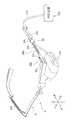
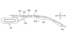
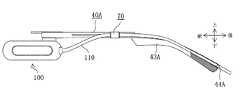
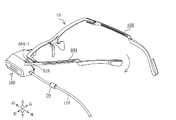
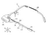
第1の実施形態に係る網膜走査型ディスプレイ1の外観全体構成について図1および図2を参照して説明する。図1は、眼鏡型のフレーム10が装着者に装着された状態を示し、図2は、装着者からフレーム10が取り外された状態を示している。網膜走査型ディスプレイ1は、眼鏡型のフレーム10と、そのフレーム10に取り付けられる画像表示ユニット100と、その画像表示ユニット100に接続ライン110を介して接続される外部装置200とから構成される。なお、本明細書および図面において、上下方向、前後方向および左右方向は、図1に示す装着者を基準として、図1に矢印で示す方向を指す。<Overall appearance configuration>
An overall appearance configuration of the
〈フレームの構成〉
眼鏡型のフレーム10の詳細な構成について図3ないし図6を参照して説明する。図3は、画像表示ユニット100が取り外されたフレーム10を示す斜視図であり、図4は、フレーム10を上方から見た平面図であり、図5は、フレーム10の中央部分のみを前方から見た正面図であり、図6は、フレーム10の左側部分を示す左側面図である。図3において、フレーム10は、フロント部20と、左右一対のヨロイ部30A、30Bと、左右一対のテンプル部40A、40Bとを有している。本実施形態のフレーム10、フロント部20、ヨロイ部30A、30B、テンプル部40A、40Bが、本発明のフレーム、フロント部、ヨロイ部、テンプル部の一例であり、画像表示ユニット100が、本発明の画像表示ユニットの一例である。<Frame configuration>
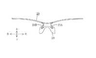
A detailed configuration of the eyeglass-
フロント部20は、図1に示すフレーム10の装着状態において、装着者の左右方向に延び、その中央部分から左右両側端に向かって上方に傾斜して形成されている。図4および図5に示すように、一対の垂下部21A、21Bが、フロント部20の中央部分を切欠溝22により切欠いて折り曲げることにより形成されている。鼻装着部23が、両垂下部21A、21Bに固定され、フレーム10の装着状態において装着者の鼻の上に装着される。 The
図4に示すように、左右一対のヨロイ部30A、30Bが、フロント部20の左右両側端に固定され、左右方向に開くように斜め後方に延びている。両ヨロイ部30A、30Bは、フロント部20と一体に形成されている。左右一対のテンプル部40A、40Bは、上下方向に延びる取付ねじ41A、41Bにより、両ヨロイ部30A、30Bの後端に回動可能に取り付けられている。すなわち、両テンプル部40A、40Bは、取付ねじ41A、41Bの上下方向に延びる軸線を中心に回動可能である。 As shown in FIG. 4, a pair of left and right armored portions 30 </ b> A and 30 </ b> B are fixed to the left and right side ends of the
両テンプル部40A、40Bは、テンプル本体42A、42Bと、耳装着部分43A、43Bと、接続ライン110を保持するためのライン保持溝44A、44Bとをそれぞれ有している。両テンプル部40A、40Bは同じ構成であるので、左側に位置するテンプル部40Aについてのみ図6を参照して説明する。 Both
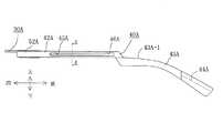
テンプル本体42Aは、取付ねじ41Aにより、ヨロイ部30Aの後端に回動可能に取り付けられ、図6に示すように前後方向に直線状に延びている。前後方向に延びる長孔45Aは、テンプル本体42Aに形成されている。テンプル本体42Aにおいて長孔45Aが形成された領域は、図2および図6に示すように、ヨロイ部30Aとテンプル本体42Aとの取付位置、すなわち取付ねじ41Aの取付位置より後方に存在する。開口46Aは、長孔45Aの後端に連続して形成され、上下方向の寸法が長孔45Aより大きく設定されている。 The temple
耳装着部分43Aは、テンプル本体42Aの後端に固定され、斜め後方に湾曲して形成されている。また、図4に示すように、耳装着部分43A、43Bは、左右方向に閉じるように斜め後方に延びている。図6において、耳装着部分43Aは、長孔45Aが形成された領域より下方の位置でテンプル本体42Aに固定され、耳装着部分43Aの上面43A−1は、長孔45Aが形成された領域より下方に位置している。 The
ライン保持溝44Aは、耳装着部分43Aの最も後端において、耳装着部分43Aの左側面、すなわちフレーム10の装着状態において装着者の側頭部とは接触しない耳装着部分44Aの外部側面に沿って形成されている。 The
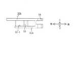
左右に延びる長手方向と直交するフロント部20の断面形状は、取付ねじ41A、41Bの軸線に平行な方向である上下方向の長さ(縦方向の長さ)より前後方向の長さ(横方向の長さ)が大きい形状である。図4のA−A線に従うフロント部20の断面が、図7(A)に示されており、縦方向の長さDL1より横方向の長さDW1が大きく設定されている。前後に延びる長手方向と直交する両ヨロイ部30A、30Bの断面形状は、上下方向の長さ(縦方向の長さ)より左右方向の長さ(横方向の長さ)が大きい形状である。図4のB−B線に従うヨロイ部30Bの断面が、図7(B)に示されており、縦方向の長さDL2より横方向の長さDW2が大きく設定されている。これに対して、前後に延びる長手方向と直交する両テンプル本体42A、42Bの断面形状は、上下方向の長さ(縦方向の長さ)より左右方向の長さ(横方向の長さ)が小さい形状である。図6のC−C線に従うテンプル本体42Aの断面が、図7(C)に示されており、縦方向の長さDL3より横方向の長さDW3が小さく設定されている。フロント部20および両ヨロイ部30A、30Bは、両テンプル本体42A、42Bより、縦方向の長さに対する横方向の長さの比率が大きいことから、フレーム10を装着するときに取付ねじ41A、41Bの軸線の回りに作用する曲げモーメントにより生ずる変形が小さい。 The cross-sectional shape of the
上記の断面形状における相違に加え、フロント部20および両ヨロイ部30A、30Bは、純チタンから構成され、両テンプル本体42A、42Bは、βチタンから構成されており、これらの部分は構成材料も相違する。純チタンはβチタンよりヤング率(縦弾性係数)が大きいことから、フロント部20および両ヨロイ部30A、30Bは、両テンプル本体42A、42Bより、引張力および圧縮力に対する剛性が大きく、変形し難い。 In addition to the above differences in cross-sectional shape, the
鼻装着部23および耳装着部分44A、44Bは、装着者に直接接触する部分であることから、装着者がフレーム10の装着時に違和感をもたないように適度の弾性を有する合成樹脂材料から構成されている。 Since the
〈保持機構の構成〉
左右一対のヨロイ部30A、30Bの中で、装着者が希望する側のヨロイ部に装着された画像表示ユニット100の装着状態を保持するために、保持機構50が設けられている。本実施形態では、画像表示ユニット100が左側のヨロイ部30Aに取り付けられることから、保持機構50は、左側のヨロイ部30Aにおける装着状態を保持するのに適した構成となっている。保持機構50の構成について、主に図3および図8を参照して説明する。図8は、画像表示ユニット100を後方から見た図面である。保持機構50は、ヨロイ部30A、30Bに設けられた左右一対の延出部51A、51Bと、テンプル部40A、40Bに設けられた左右一対の押圧部52A、52Bと、画像表示ユニット100に取り付けられた左側取付用の取付具53とから構成されている。本実施形態の保持機構50が、本発明の保持機構の一例である。<Configuration of holding mechanism>
A holding
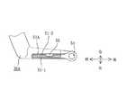
両延出部51A、51Bは同じ構成であるので、延出部51Aについてのみ説明する。図3に示すように、延出部51Aは、ヨロイ部30Aの下面に固定され、取付ねじ41Aの取付位置から前方に延びている。図9および図10は、ヨロイ部30Aからテンプル部40Aを取り外した状態においてヨロイ部30Aを拡大して示す図面であり、図9はヨロイ部30Aの一部を破断して延出部51Aを上方から見た平面図であり、図10はヨロイ部30Aの左側面図である。図9において、第1案内溝51−1および第2案内溝51−2が、延出部51Aの左右両側面にそれぞれ形成され、取付ねじ41Aが挿入される取付孔54の近傍から前方に延びており、前方に開放している。係止溝55が、第2案内溝51−2の中央部分において、第2案内溝51−2に連続して形成されている。 Since both
両押圧部52A、52Bは同じ構成であるので、押圧部52Aについてのみ説明する。図3に示すように、押圧部52Aは、取付ねじ41Aの取付位置から前方に、テンプル部40Aから延びており、テンプル本体42Aと一体に形成されている。図11および図12は、ヨロイ部30Aにテンプル部40Aを取り付けた状態においてヨロイ部30Aを拡大して示す図面であり、図11はヨロイ部30Aおよびテンプル部40Aを上方から見た平面図であり、図12はヨロイ部30Aおよびテンプル部40Aの左側面図である。押圧部52Aは、延出部51Aとの間で取付具53の一部分を挟持するために、図11に示すように、延出部51Aと対向する側に押圧可能面52A−1を有する。押圧部52Aは、延出部51Aより、前方に長く形成されている。また、押圧部52Aは、上下方向においてテンプル本体42Aと同じ寸法に設定され、第1案内溝51−1より、上下方向に大きく形成されている。 Since both
延出部51Aは、ヨロイ部30Aと同様に、純チタンから構成され、押圧部52Aは、テンプル本体42Aと同様に、βチタンから構成されている。前後に延びる長手方向と直交する押圧部52Aの断面形状は、テンプル本体42Aと同様に、上下方向の長さ(縦方向の長さ)より左右方向の長さ(横方向の長さ)が小さい形状である。上記の構成材料および断面形状から、押圧部52Aは、延出部51Aよりも弾性を有すると共に、フレーム10を装着するときに取付ねじ41Aの軸線の回りに作用する曲げモーメントにより生ずる変形が延出部51Aよりも大きくなる。本実施形態の延出部51Aおよび案内溝51−1、51−2が、本発明の第1の係合部の一例であると共に、延出部および案内溝の一例である。また、本実施形態の押圧部52Aは、本発明の押圧部の一例である。 The
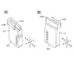
図8において、取付具53は、画像表示ユニット100の後方の右側面に、取付ねじ56により取り付けられる。図13は、取付具53を拡大して示しており、図13(A)は取付具53を後方から見た図面であり、図13(B)は取付具53を前方から見た図面である。取付具53は、取付本体部分57と、その取付本体部分57の上部に設けられた一対の挟持片58A、58Bとを有し、合成樹脂材料により一体成形されている。5つの取付孔59が、取付本体部57の後方寄りに、上下方向に異なる位置で形成されている。装着者は、5つの取付孔59の中で、希望する取付孔59に取付ねじ56の軸部分を挿入して、画像表示ユニット100に設けられたねじ孔に螺合させることにより、画像表示ユニット100に対して取付具53を任意の高さで取り付けることができる。 In FIG. 8, the
一対の挟持片58A、58Bは、延出部51Aを両側から挟持するもので、第1挟持片58Aは、取付本体部分57の上部に固定されている。第2挟持片58Bは、第1挟持片58Aに対して、接近および離隔できるように弾性を有する。第2挟持片58Bは、自由端の近傍に、第1挟持片58Aに向かって膨出する係止突起60を有し、その自由端の先端部は、第1挟持片58Aから離れる方向に屈曲されている。画像表示ユニット100がヨロイ部30Aに装着されるとき、第1および第2挟持片58A、58Bは、延出部51Aの第1および第2案内溝51−1、51−2に前方の開放部分からそれぞれ嵌入し、係止突起60は、延出部51Aの係止溝55と係合する。 The pair of sandwiching pieces 58 </ b> A and 58 </ b> B sandwich the extending portion 51 </ b> A from both sides, and the first sandwiching piece 58 </ b> A is fixed to the upper portion of the attachment
図13(B)において、段部61が、第1挟持片58Aと取付本体部分57との結合部分に形成されている。図2に示すように、画像表示ユニット100がヨロイ部30Aに装着されたとき、押圧部52Aが、押圧可能面52A−1と対向する第1挟持片58Aの左側面58A−1を押圧することができるように、段部61は、押圧部52Aの進入を許容する空間を形成している。図11に示す押圧部52Aの押圧可能面52A−1は、前後方向において第1挟持片58Aの左側面58A−1よりも長く形成され、上下方向において左側面58A−1と同じ寸法に形成されている。すなわち、押圧可能面52A−1は、その押圧可能面と対向する左側面58A−1よりも大きな面積を有している。本実施形態の一対の挟持片58A、58Bを備えた取付具53が、本発明の第2の係合部の一例であり、一対の挟持片58A、58Bが、本発明の一対の挟持片の一例である。 In FIG. 13B, a stepped
〈接続ラインの保持構成〉
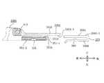
接続ライン110は、図2に示すように、テンプル部40Aに沿って保持される。接続ライン110を保持するための構成について図14ないし図16を参照して説明する。図14は、接続ライン110が保持されたテンプル部40Aの左側面図であり、図15は、テンプル本体42Aを右側から拡大して見た図面である。図16は、接続ライン110を保持するための保持部材70を拡大して示す図面であり、図16(A)は保持部材70を上方から見た平面図であり、図16(B)は保持部材70を前方から見た正面図である。図14および図15において、保持部材70は、長孔45Aに摺動可能に取り付けられている。図16において、保持部材70は、長孔45Aと嵌合可能な摺動部分71と、ライン保持部分72と、板状部分73とを有し、合成樹脂材料により一体成形されている。<Connection line retention configuration>
As shown in FIG. 2, the
図16(B)において、ライン保持部分72は、摺動部分71の左側面に連続して形成され、接続ライン110が前後方向に挿通可能な貫通孔74を有している。板状部分73は、摺動部分71の右側面に連続して形成されている。板状部分73は、図15に示すように、長孔45Aより、上下方向の寸法が大きく設定される一方、左右方向において開口46Aを通過することができるように、開口46Aより、上下および前後の方向の寸法が僅かに小さく設定されている。摺動案内溝47Aが、テンプル本体42Aの右側面42A−1において、開口46Aから前方に延び、長孔45Aに沿って形成されている。摺動案内溝47Aは、上下方向において、開口46Aと同じ寸法である。板状部分73は、開口46Aを通過した後に摺動案内溝47Aと嵌合することにより、摺動案内溝47Aに沿って摺動可能に構成される。 In FIG. 16B, the
ライン保持部分72および板状部分73は、図16(A)および図17に示すように、テンプル本体42Aの左側面42A−2と接触可能な摺動面72−1と、摺動案内溝47Aと接触可能な摺動面73−1とをそれぞれ有している。摺動面72−1は、テンプル本体42Aの左側面42A−2に向かって凸形状となり、前後方向に延びる曲面に形成されている。同様に、摺動面73−1は、摺動案内溝47Aの摺動面47A−1に向かって凸形状となり、前後方向に延びる曲面に形成されている。図4に示すように、左側のテンプル本体42Aは、左方向に凸形状となるように僅かに湾曲して形成され、右側のテンプル本体42Bは、右方向に凸形状となるように僅かに湾曲して形成されている。図17は、左側のテンプル本体42Aの一部を破断して板状部分73と摺動案内溝47Aとの配置状態を拡大して示す図面である。フレーム10が装着されていない自然状態でもテンプル本体42Aは湾曲している。板状部分73の摺動面73−1の曲率半径R1は、この自然状態で湾曲したテンプル本体42Aの右側面42A−1の曲率半径、厳密にはテンプル本体42Aに形成された摺動面47A−1の曲率半径R2より、充分に小さく設定されている。フレーム10が装着されたときは、テンプル本体42Aは、その湾曲状態の曲率半径が大きくなるように変形することから、摺動面73−1の曲率半径R1は、フレーム10の装着または非装着に拘わらず、テンプル本体42Aの右側面42A−1の曲率半径より、充分に小さい関係が維持される。この曲率半径の設定により、摺動面73−1は常に摺動面47A−1と点接触の関係となると共に、摺動面72−1も左側面42A−2と点接触の関係となり、保持部材70はテンプル本体42Aの湾曲状態に関係なく常に円滑に摺動することができる。 As shown in FIGS. 16A and 17, the
図2および図14に示すように、接続ライン110は、画像表示ユニット100から後方に延び、テンプル本体42Aの左側において保持部材70により保持されている。接続ライン100は、図14に示すように、耳装着部分43Aの上面43A−1より上方の空間に向かって、保持部材70から導出されている。図18は、ライン保持溝44Aが形成された耳装着部分43Aの自由端を断面にして示す図面である。図18に示すように、ライン保持溝44Aは、接続ライン100をその内部に完全に収容することかできる深さの溝に形成されている。 As shown in FIGS. 2 and 14, the
〈画像表示ユニットおよび外部装置の構成〉
画像表示ユニット100は、可能な限り軽量化されるのが望ましいことから、必要最低限の光学系のみを内蔵する構成であり、その他の光学系は外部装置200に内蔵されている。本実施形態では、外部装置200は、3原色の映像信号供給回路、レーザ光源、レーザ駆動回路、3原色のレーザ光の結合光学系などを内蔵している。接続ライン110は、結合された3原色のレーザ光を伝送する光ファイバから構成されている。画像表示ユニット100は、コリメートレンズ、水平走査部、垂直走査部、接眼レンズなどの光学系を内蔵している。画像表示ユニット100は、図8に示すように、光照射用開口101を有し、その開口101の近傍に透明のハーフミラー102が角度調整可能に取り付けられている。本実施形態の画像表示ユニット100が内蔵するコリメートレンズ、水平走査部、垂直走査部、接眼レンズなどの光学系が、本発明の画像表示ユニットが内蔵する光学系の一例であり、画像表示ユニット100が照射するレーザ光が、本発明の画像表示ユニットが発生する画像光の一例である。<Configuration of image display unit and external device>
Since it is desirable that the
画像表示ユニット100は、接続ライン110により伝達されたレーザ光を内蔵の光学系を介してハーフミラー102に照射し、ハーフミラー102により屈折されたレーザ光が装着者の眼に照射される。装着者は、レーザ光が眼に照射されていない場合は、ハーフミラー102を通して眼前の背景を見ることができる。 The
《動作および作用》
以上説明したように構成された本実施形態の動作および作用について、図19ないし図22を参照して説明する。図19ないし図22は、画像表示ユニット100をフレーム10に取り付ける手順を示す説明図であり、フレーム10を後方から見た図面である。先ず、装着者は、画像表示ユニット100を左右両側のヨロイ部30A、30Bのいずれに取り付けるかを決める必要がある。装着者にとって左右両側のいずれが見易い側かが、装着者個人ごとに異なる。このため、画像表示ユニット100に取り付けられる取付具の形状も、取り付ける側に応じて異なる。図13に示す取付具53は、左側のヨロイ部30Aに画像表示ユニット100を取り付けるための形状を有している。<Operation and action>
The operation and action of the present embodiment configured as described above will be described with reference to FIGS. FIGS. 19 to 22 are explanatory views showing a procedure for attaching the
右側のヨロイ部30Bに画像表示ユニット100を取り付ける場合には、図23に示す右側取付用の取付具153が使用される。取付具153は、図13に示す取付具53と異なり、第2挟持片158Bが第1挟持片158Aの左側に位置するように形状が変更されており、第1挟持片158Aは取付本体部分157の上部に固定されている。取付具153の他の構成は、図13に示す取付具53と同じ構成である。また、画像表示ユニット100は、図8に示す姿勢から180度回転した状態で使用され、接続ライン110により伝送されるレーザ光が表す映像も、180度回転して使用される。 When the
本実施形態では、画像表示ユニット100が左側のヨロイ部30Aに取り付けられる場合について以下に説明する。 In the present embodiment, a case where the
〈取付具の取り付け〉
装着者は、画像表示ユニット100をフレーム10からどの程度下方の位置に取り付けるのかを決める必要がある。装着者がフレーム10より前方のスクリーンや書類を見ることが多く、視線を下方にずらせて画像表示ユニット100の表示画像を見ることが少ない場合には、画像表示ユニット100の配置位置は、眼前に広い視界を確保するためにフレーム10に対して比較的下方の位置に決められる。一方、装着者が画像表示ユニット100の表示画像を専ら見ることが多く、視線を変更する必要がない場合には、画像表示ユニット100の配置位置は、眼前に広い視界を確保する必要がないことからフレーム10に対して近接した位置に決められる。装着者が、画像表示ユニット100の使用目的に応じて、取付具53の5つの取付孔59のいずれかの孔に取付ねじ56を挿入し、取付具53を画像表示ユニット100に取り付ける。<Attaching the fixture>
The wearer needs to determine how much the
〈画像表示ユニットの取り付け〉
装着者は、フレーム10を装着しない状態で、図19に示すように、左側のテンプル部40Aを反時計回りに回動させ、押圧部52Aを延出部51Aから離間させる。装着者は、取付具53の両挟持片58A、58Bを延出部51Aの両案内溝51−1、51−2に前方から嵌入する。この嵌入操作により、第2挟持片58Bの係止突起60が延出部51Aの係止溝55に嵌合する。両挟持片58A、58Bが両案内溝51−1、51−2に嵌合することにより、画像表示ユニット100は、フレーム10に対して上下方向の位置が決められ、フレーム10から落下することなくヨロイ部30Aに保持される。また、係止突起60が係止溝55に嵌合することにより、画像表示ユニット100は、フレーム10に対して前後方向の位置が決められ、案内溝51−1、51−2から前方に抜けることなくヨロイ部30Aに保持される。図20は、画像表示ユニット100がヨロイ部30Aに取り付けられた状態を示している。<Attaching the image display unit>
As shown in FIG. 19, the wearer turns the
装着者は、画像表示ユニット100の取り付け状態を確実に保持するために、図20に示すテンプル部40Aの状態から時計回り方向にテンプル部40Aを回動させ、押圧部52Aを第1挟持片58Aの左側面58A−1に押し付ける。図21は、押圧部52Aが第1挟持片58Aを押圧している状態を示している。第1挟持片58Aは、延出部51Aと押圧部52Aとにより挟持され、画像表示ユニット100は、テンプル部40Aの回動という簡単な操作のみで、取付ねじの締め付けなどの特別な作業を必要とすることなく、ヨロイ部30Aに確実に保持される。延出部51Aが固定されたヨロイ部30Aは、押圧部52Aよりも、テンプル部40Aの回動操作により生ずる曲げモーメントに対して、変形し難い大きな剛性を有することから、画像表示ユニット100の配置位置がフロント部20およびヨロイ部30Aに対して変化することが抑制される。一方、押圧部52Aは、弾性を有することから、第1挟持片58Aの左側面58A−1に充分な保持弾性力を作用させることができる。しかも、押圧部52Aの押圧可能面52A−1は、延出部51Aの第1案内溝51−1が形成された上下および前後の方向の領域より大きな面積を有すると共に、第1挟持片58Aの左側面58A−1の面積より大きな面積を有することから、押圧部52Aは、延出部51Aおよび第1挟持片58Aの全体に押圧力を作用させ、画像表示ユニット100が延出部51Aから前方に抜けることを確実に防止することができる。 The wearer rotates the
〈接続ラインの保持操作〉
図21に示すように、接続ライン110は、保持部材70の貫通孔74に挿通された状態にある。図21に示す状態で、装着者は、保持部材70の板状部分73をテンプル本体42Aの左側面から開口46Aに嵌入する。図15は、板状部材73を開口46Aに嵌入した直後の状態を示している。装着者は、図15に示す状態から、保持部材70を長孔45Aに沿って前方に摺動させることにより、保持部材70をテンプル本体42Aに取り付けることができる。<Connection line holding operation>
As shown in FIG. 21, the
装着者は、保持部材70から後方に延びる接続ライン110がフレーム10の装着時に邪魔にならないように、接続ライン110をライン保持溝44Aに嵌める。ライン保持溝44Aは接続ライン110を完全に収容できる深さを有し、ライン保持溝44Aは接続ライン110の嵌入により僅かに弾性変形することから、接続ライン110は、弾性力によりライン保持溝44Aの内部に保持される。図22は、接続ライン110の保持操作が完了した状態を示している。 The wearer fits the
〈フレームの装着操作〉
装着者は、図22に示すように接続ライン110が保持された状態のフレーム10を頭部に装着し、図1に示すように鼻装着部23を鼻の上に装着すると共に、耳装着部分43Aを耳に装着する。左右両側のテンプル部40A、40Bの間隔は、装着者の頭部の大きさに応じて変化し、通常は、図4に示す自然状態の間隔から広がることになる。この間隔の広がりにより、取付ねじ41A、41Bの軸線の回りに曲げモーメントが生ずる。取付ねじ41Aの軸線の回りには時計回り方向の曲げモーメントがテンプル本体42Aおよび押圧部52Aに作用し、押圧部52Aは弾性変形して第1挟持片58Aを延出部51Aに向かって押し付ける。フレーム10の装着状態における押圧部52Aの弾性変形により、画像表示ユニット100は一層強力な弾性保持力でヨロイ部30Aに保持される。<Frame mounting operation>
The wearer wears the
両テンプル部40A、40Bの間隔が広がったことにより、接続ライン110が、図1において画像表示ユニット100と保持部材70との間で弛むことがある。装着者は、フレーム10を装着したままで、保持部材70を前方に向かって摺動させることにより、接続ライン110の弛みを解消することができる。 The
接続ライン110は、保持部材70から後方に延びるが、図14に示すように、保持部材70から導出された直後の状態において、耳装着部分43Aの上面43A−1より上方の空間に位置している。このため、接続ライン110が装着者の耳に押し付けられることはなく、装着者に違和感を与えることはない。また、ライン保持溝44Aは、耳装着部分43Aの最も後方に形成され、フレーム10の装着状態では、図1に示すように、装着者の耳の後方に位置している。このため、ライン保持溝44Aが形成された部分が装着者の耳を圧迫することはなく、ライン保持溝44Aから下方に垂れ下がる接続ライン110が装着者の耳や後頭部に接触することを極力抑えることができる。 The
装着者は、フレーム10を装着したままで、図8に示すハーフミラー102の角度を調整することにより、画像表示ユニット100の表示画像が鮮明に見えるように眼に照射されるレーザ光の照射方向を変更することができる。また、画像表示ユニット100は取付具53に対して取付ねじ56の軸線の回りに角度位置を僅かに調整することができることから、装着者は、フレーム10を装着したままで、フレーム10に対する画像表示ユニット100のハーフミラー102の上下方向の位置を微調整することができる。 The wearer adjusts the angle of the
[第2の実施形態]
次に、本発明の眼鏡型の画像表示装置を単眼タイプの網膜走査型ディスプレイに適用した第2の実施形態について、図24ないし図26を参照して説明する。第2の実施形態は、ヨロイ部、テンプル部、延出部、押圧部および一対の挟持片の構成について第1の実施形態と相違し、他の構成は第1の実施形態と同じであるので、同じ構成については同じ番号または記号を付して説明する。図24は、左側のヨロイ部330Aと左側のテンプル部340Aとの連結構成を拡大して示す平面図であり、図25は、図24に示すヨロイ部330Aの後方部分を破断して延出部351Aの構成を拡大して示す平面図であり、図26は、ヨロイ部330A、延出部351Aおよびテンプル部340Aを左方から見た左側面図である。[Second Embodiment]
Next, a second embodiment in which the eyeglass-type image display device of the present invention is applied to a monocular retinal scanning display will be described with reference to FIGS. The second embodiment is different from the first embodiment in the configuration of the armored portion, the temple portion, the extending portion, the pressing portion, and the pair of clamping pieces, and the other configurations are the same as those in the first embodiment. The same components will be described with the same numbers or symbols. 24 is an enlarged plan view showing a connection configuration between the
図24において、テンプル部340Aのテンプル本体342Aが、ヨロイ部330Aに取付ねじ41Aにより回動可能に取り付けられている。ヨロイ部330Aは、取付ねじ41Aの取付位置より後方に延びる支持部分331Aを有し、ヨロイ部330Aおよび支持部分331Aは、純チタンから構成されている。また、前後に延びる長手方向と直交するヨロイ部330Aの断面形状および支持部分331Aの断面形状は、第1の実施形態と同様に、上下方向の長さ(縦方向の長さ)より左右方向の長さ(横方向の長さ)が大きい形状である。テンプル部340Aのテンプル本体342Aは、βチタンから構成され、前後に延びる長手方向と直交するテンプル本体342Aの断面形状は、第1の実施形態と同様に、上下方向の長さ(縦方向の長さ)より左右方向の長さ(横方向の長さ)が小さい形状である。 In FIG. 24, a temple
延出部351Aが、支持部分331Aの下面に固定され、取付ねじ41Aの取付位置の近傍から後方に延びている。延出部351Aは、ヨロイ部330Aと同様に、純チタンから構成されている。第1および第2案内溝351−1、351−2が、延出部351Aの左右両側面に形成され、後方において開放している。係止溝355が、第2案内溝351−2の中央部分に形成されている。 The extending
取付具353が、画像表示ユニット100に取付ねじ56により取り付けられる。取付具353は、第1および第2挟持片358A、358Bを有しており、第1挟持片358Aは、第1の実施形態と同様に、取付本体部分57に固定され、第2挟持片358Bは、第1挟持片358Aに対して、接近および離隔できるように弾性を有する。第2挟持片358Bは、自由端の近傍に、第1挟持片358Aに向かって膨出する係止突起360を有し、その自由端の先端部は、第1挟持片358Aから離れる方向に屈曲されている。画像表示ユニット100がヨロイ部330Aに装着されるとき、第1および第2挟持片358A、358Bは、延出部351Aの第1および第2案内溝351−1、351−2に後方の開放部分からそれぞれ嵌入し、係止突起360は、延出部351Aの係止溝355と係合する。 The
両挟持片358A、358Bが両案内溝351−1、351−2に嵌合された状態で、図25において、テンプル部340Aが時計回り方向に回動されると、テンプル本体342Aの左側面342A−1が、第1挟持片358Aの右側面358A−1を延出部351Aに向かって押し付ける。テンプル本体342Aの左側面342A−1は、第1の実施形態における押圧部52Aの押圧可能面52A−1と同様な押圧作用を有し、画像表示ユニット100をヨロイ部330Aに保持することができる。 When the
[変形例]
本発明は、上記実施形態に限定されることはなく、その趣旨を逸脱しない限り、種々の変更を加えることができる。[Modification]
The present invention is not limited to the embodiment described above, and various modifications can be made without departing from the spirit of the present invention.
(1)上記実施形態は、フレーム10の左右両側の一方に画像表示ユニット100を取り付ける単眼型の画像表示装置であったが、2つの画像表示ユニットをフレームの左右両側にそれぞれ取り付ける両眼型の画像表示装置であってもよい。(1) The above embodiment is a monocular image display device in which the
(2)上記実施形態は、両挟持片58A、58B、358A、358Bを、延出部51A、351Aに対して前方または後方から嵌入する構成であったが、両挟持片を延出部に対して左右方向において嵌入する構成であってもよい。この変形例では、両挟持片の嵌入操作時に、押圧部またはテンプル本体を延出部から離間させるためにテンプル部を大きく回動させる必要があるが、この回動操作のみで画像表示ユニットをヨロイ部に保持できることは、上記実施形態と同様に変形例でも可能である。また、両挟持片を延出部に対して下方から嵌入する構成であってもよい。この変形例では、両挟持片が延出部から下方に抜けるのを防止するために、係止溝および係止突起を上下方向と直交する方向に形成する必要がある。(2) In the above embodiment, the both sandwiching
(3)上記実施形態は、延出部51A、351Aに第1挟持片58A、358Aを押し付ける押圧部52Aまたはテンプル本体342Aを設けることにより、画像表示ユニット100をヨロイ部30A、330Aに保持する保持力を高めることができる構成である。しかし、必要最低限の保持力は、第2挟持片58B、358Bと、係止溝55、355および係止突起60、360とにより確保することができるため、押圧部52Aまたはテンプル本体342Aにより押し付ける構成は必ずしも必要ではない。(3) In the above embodiment, the
(4)上記実施形態は、延出部51A、351Aをヨロイ部30A、330Aの下面に固定して形成しているが、延出部をヨロイ部の上面に固定して形成してもよい。この変形例では、取付具の両挟持片が延出部に嵌合したとき、その取付具の下方への移動はヨロイ部の上面で規制され、画像表示ユニット100の上下方向の位置を保持することができる。(4) In the above embodiment, the extending
(5)上記実施形態では、フロント部20およびヨロイ部30A、330Aがテンプル本体42A、342Aおよび押圧部52Aより大きな剛性を有するように、構成材料および断面形状の両者が異なる構成であるが、構成材料および断面形状のいずれか一方が異なる構成であってもよい。(5) In the above embodiment, both the constituent material and the cross-sectional shape are different so that the
1 画像表示装置
10 フレーム
20 フロント部
30A、30B、330A ヨロイ部
40A、40B テンプル部
42A、342A テンプル本体
43A 耳装着部分
50 保持機構
51A、351A 延出部
52A 押圧部
58A,58B、158A、158B、358A、358B 挟持片
100 画像表示ユニット
110 接続ライン
DESCRIPTION OF
Claims (18)
Translated fromJapanese装着者に画像を表示するために画像光を発生する光学系を内蔵する画像表示ユニットと、
前記画像表示ユニットを前記ヨロイ部に取り外し可能に保持する保持機構とを備え、
前記保持機構は、
前記ヨロイ部に固定された第1の係合部と、
前記画像表示ユニットに設けられ、前記第1の係合部と係合可能な第2の係合部と、
前記第2の係合部が前記第1の係合部と係合した状態で前記テンプル部が装着者の耳に装着されたときに、前記第2の係合部を前記第1の係合部に対して押圧するように前記テンプル部に設けられた押圧部とを備え、
前記第1の係合部は、
前後方向において前記ヨロイ部の後端から延びる2つの側面を有し、前記ヨロイ部に固定された延出部と、
その延出部の少なくとも1つの側面に沿って前後方向に形成された案内溝とを備え、
前記第2の係合部は、前記延出部の2つの側面を両側から挟持する一対の挟持片を備え、
前記一対の挟持片の少なくとも一方の挟持片は、前記案内溝と嵌合可能であり、
前記押圧部は、前記ヨロイ部の後端に回動可能に取り付けられた前記テンプル部の取付部分から前後方向に延び、前記一方の挟持片を前記案内溝に向かって押圧する眼鏡型の画像表示装置。A front part that extends in the left-right direction in front of the wearer's eyes and is attached to the nose of the wearer, and an armor part that is fixed to at least one side end of the left and right side ends of the front part and extends rearward from the one side end And a frame including a temple part attached to the wearer's ear and attached to the armor part so as to be rotatable about an axis in the vertical direction,
An image display unit including an optical system for generating image light to display an image to the wearer;
A holding mechanism for detachably holding the image display unit on the armor part,
The holding mechanism is
A first engagement portion fixed to the armor portion;
A second engagement portion provided in the image display unit and engageable with the first engagement portion;
When the temple portion is attached to the ear of the wearer with the second engagement portion engaged with the first engagement portion, the second engagement portion is moved to the first engagement. A pressing part provided in the temple part so as to press against the part,
The first engagement portion is
An extension portion having two side surfaces extending from the rear end of the end portion in the front-rear direction, and fixed to the end portion;
A guide groove formed in the front-rear direction along at least one side surface of the extension part,
The second engagement portion includes a pair of clamping pieces that clamp the two side surfaces of the extending portion from both sides,
At least one sandwiching piece of the pair of sandwiching pieces can be fitted with the guide groove,
The pressing portion extends in the front-rear direction from an attachment portion of the temple portion rotatably attached to the rear end of the armor portion, and presses the one clamping piece toward the guide groove. apparatus.
前記一対の挟持片は、前記案内溝の開放部分から嵌合して前記案内溝に沿って案内される請求項1から請求項3のいずれかに記載の眼鏡型の画像表示装置。The guide groove is formed on both side surfaces of the extensionpart in an open state at theend of the extension part,
It said pair of holding pieces, the eyeglass-type image display apparatus according to any one of claims1 to3, fitted from the open portion of the guide groove is guided along the guide groove.
装着者に画像を表示するために画像光を発生する光学系を内蔵する画像表示ユニットと、
前記画像表示ユニットを前記ヨロイ部に取り外し可能に保持する保持機構とを備え、
前記保持機構は、
前記ヨロイ部に固定された第1の係合部と、
前記画像表示ユニットに対して取り外し可能に設けられ、前記第1の係合部と係合可能な第2の係合部と、
前記第2の係合部が前記第1の係合部と係合した状態で前記テンプル部が装着者の耳に装着されたときに、前記第2の係合部を前記第1の係合部に対して押圧するように前記テンプル部に設けられた押圧部とを備える眼鏡型の画像表示装置。A front part that extends in the left-right direction in front of the wearer's eyes and is attached to the nose of the wearer, and an armor part that is fixed to at least one side end of the left and right side ends of the front part and extends rearward from the one side end And a frame including a temple part attached to the wearer's ear and attached to the armor part so as to be rotatable about an axis in the vertical direction,
An image display unit including an optical system for generating image light to display an image to the wearer;
A holding mechanism for detachably holding the image display unit on the armor part,
The holding mechanism is
A first engagement portion fixed to the armor portion;
A second engagement portion provided detachably with respect to the image display unit and engageable with the first engagement portion;
When the temple portion is attached to the ear of the wearer with the second engagement portion engaged with the first engagement portion, the second engagement portion is moved to the first engagement. An eyeglass-type image display devicecomprising: a pressing portion provided in the temple portion so as to press against the portion .
前記突出部は、前記画像表示ユニットに設けられる請求項6に記載の眼鏡型の画像表示装置。The plurality of engagement holes are formed on the second engagement portion engaged with the first engagement portion so that the positions in the vertical direction are different from each other.
The eyeglass-type image display device according to claim6 , wherein the protrusion is provided in the image display unit.
装着者に画像を表示するために画像光を発生する光学系を内蔵する画像表示ユニットと、
前記画像表示ユニットを前記ヨロイ部に取り外し可能に保持する保持機構とを備え、
前記保持機構は、
前記ヨロイ部に固定された第1の係合部と、
前記画像表示ユニットに設けられ、前記第1の係合部と係合可能な第2の係合部と、
前記第2の係合部が前記第1の係合部と係合した状態で前記テンプル部が装着者の耳に装着されたときに、前記第2の係合部を前記第1の係合部に対して押圧するように前記テンプル部に設けられ、前記第1の係合部と前記第2の係合部とが係合する係合領域より、大きな領域を有する押圧可能面を備える押圧部とを備える眼鏡型の画像表示装置。A front part that extends in the left-right direction in front of the wearer's eyes and is attached to the nose of the wearer, and an armor part that is fixed to at least one side end of the left and right side ends of the front part and extends rearward from the one side end And a frame including a temple part attached to the wearer's ear and attached to the armor part so as to be rotatable about an axis in the vertical direction,
An image display unit including an optical system for generating image light to display an image to the wearer;
A holding mechanism for detachably holding the image display unit on the armor part,
The holding mechanism is
A first engagement portion fixed to the armor portion;
A second engagement portion provided in the image display unit and engageable with the first engagement portion;
When the temple portion is attached to the ear of the wearer with the second engagement portion engaged with the first engagement portion, the second engagement portion is moved to the first engagement. A pressing portion provided on the temple portion so as to press against the portion, and having a pressable surface having a larger area than an engaging area where the first engaging portion and the second engaging portion engage. A glasses-type image display device.
前記第2の係合部は、前記延出部の2つの側面を両側から挟持する一対の挟持片を備え、
前記押圧部は、前記ヨロイ部の後端に回動可能に取り付けられた前記テンプル部の取付部分から前後方向に延び、前記一対の挟持片の一方の挟持片を前記延出部の側面に向かって押圧し、
前記一対の挟持片が前記延出部の側面を挟持している状態において、前記押圧部は、前記押圧部と対向する前記一方の挟持片の対向面より、大きな面積を有する押圧可能面を備える請求項8に記載の眼鏡型の画像表示装置。The first engagement portion has two side surfaces extendingfrom the rear end of the armor portion in the front-rear direction, and includes an extension portion fixed to the armor portion.
The second engagement portion includes a pair of clamping pieces that clamp the two side surfaces of the extending portion from both sides,
The pressing portion extends in afront-rear direction from an attachment portion of the temple portion that is rotatably attached to a rear end of the armor portion, and one clamping piece of the pair of clamping pieces faces a side surface of the extension portion. Press
In a state where the pair of sandwiching pieces sandwich the side surface of the extending portion, the pressing portion includes a pressable surface having a larger area than the facing surface of the one sandwiching piece facing the pressing portion. The eyeglass-type image display device according to claim8 .
装着者に画像を表示するために画像光を発生する光学系を内蔵し、画像を表示するために外部装置から接続ラインを介して信号を受け取るように構成される画像表示ユニットと、
前記画像表示ユニットを前記ヨロイ部に取り外し可能に保持する保持機構とを備え、
前記接続ラインを保持する保持部材が、前記テンプル部に沿って前後方向に摺動可能に取り付けられ、
前記テンプル部は、前後方向に延びる長孔を備え、
前記保持部材は、
前記長孔に嵌合可能な摺動部分と、
その摺動部分の一方の側面に連続して形成され、前記接続ラインを保持するライン保持部分と、
前記摺動部分の他方の側面に連続して形成され、前記長孔の幅より広い板状部分とを備える眼鏡型の画像表示装置。A front part that extends in the left-right direction in front of the wearer's eyes and is attached to the nose of the wearer, and an armor part that is fixed to at least one side end of the left and right side ends of the front part and extends rearward from the one side end And a frame including a temple part attached to the wearer's ear and attached to the armor part so as to be rotatable about an axis in the vertical direction,
An image display unit that includes an optical system that generates image light to display an image to the wearer, and is configured to receive a signal from an external device via a connection line to display the image;
A holding mechanism for detachably holding the image display unit on the armor part,
A holding member for holding the connection line is slidably attached in the front-rear direction along the temple portion,
The temple portion includes a long hole extending in the front-rear direction,
The holding member is
A sliding portion that can be fitted into the elongated hole;
A line holding portion that is continuously formed on one side surface of the sliding portion and holds the connection line;
An eyeglass-type image display device comprising a plate-like portion formed continuously on the other side surface of the sliding portion and wider than the width of the long hole .
前記保持部材は、前記開口を通して前記板状部分を挿通または離脱させることにより、前記テンプル部に着脱可能に取り付けられる請求項12に記載の眼鏡型の画像表示装置。The temple portion is continuously formed at the rear end of the elongated hole, and includes an opening having a size through which the plate-like portion can pass.
The eyeglass-type image display device according to claim12 , wherein the holding member is detachably attached to the temple portion by inserting or removing the plate-like portion through the opening.
前記板状部分の摺動面の曲率半径は、前記テンプル部の湾曲した側面の曲率半径より、小さく設定されている請求項14に記載の眼鏡型の画像表示装置。The side surface of the temple portion is bent by a bending moment acting around the axis when the temple portion is worn on a wearer's ear,
The eyeglass-type image display device according to claim14 , wherein a radius of curvature of the sliding surface of the plate-like portion is set smaller than a radius of curvature of the curved side surface of the temple portion.
前記ヨロイ部に回動可能に取り付けられた取付部分から後方に延びるテンプル本体と、
そのテンプル本体の後端に設けられ、装着者の耳に装着される耳装着部分と、
前記接続ラインを保持するために前記耳装着部分に形成されたライン保持溝とを備える請求項12から請求項15のいずれかに記載の眼鏡型の画像表示装置。The temple part is
A temple body extending rearward from an attachment part rotatably attached to the armor part;
An ear mounting portion provided at the rear end of the temple body and mounted on the wearer's ear;
The eyeglass-type image display device according to any one of claims12 to15 , further comprising a line holding groove formed in the ear mounting portion to hold the connection line.
前記耳装着部分は、前記テンプル本体において前記長孔が形成された領域より下方の位置で前記テンプル本体に連結されて後方に延びている請求項16に記載の眼鏡型の画像表示装置。The elongated hole is formed in the temple body,
17. The eyeglass-type image display device according to claim16 , wherein the ear mounting portion is connected to the temple main body and extends rearward at a position below the region where the elongated hole is formed in the temple main body.
前記一対の挟持片は、前記画像表示ユニットの上面から突出して設けられ、
前記一対の挟持片が前記延出部の側面を挟持しているとき、前記画像表示ユニットは、前記フロント部およびヨロイ部より下方に配置される請求項1から請求項4のいずれかに記載の眼鏡型の画像表示装置。The extending portion is provided to protrude from the lower surface of the armored portion,
The pair of clamping pieces are provided to protrude from the upper surface of the image display unit,
When the pair of clamping pieces are clamping the side surface of the extending portion, the image display unit, according to any one of claims1 to4, which is disposed from below the front part and the connection part Glasses-type image display device.
Priority Applications (3)
| Application Number | Priority Date | Filing Date | Title |
|---|---|---|---|
| JP2008246988AJP5212901B2 (en) | 2008-09-25 | 2008-09-25 | Glasses-type image display device |
| US12/561,205US8344965B2 (en) | 2008-09-25 | 2009-09-16 | Head mounted display device |
| EP09252212AEP2169444B1 (en) | 2008-09-25 | 2009-09-17 | Head mounted display device |
Applications Claiming Priority (1)
| Application Number | Priority Date | Filing Date | Title |
|---|---|---|---|
| JP2008246988AJP5212901B2 (en) | 2008-09-25 | 2008-09-25 | Glasses-type image display device |
Publications (2)
| Publication Number | Publication Date |
|---|---|
| JP2010081272A JP2010081272A (en) | 2010-04-08 |
| JP5212901B2true JP5212901B2 (en) | 2013-06-19 |
Family
ID=41314685
Family Applications (1)
| Application Number | Title | Priority Date | Filing Date |
|---|---|---|---|
| JP2008246988AExpired - Fee RelatedJP5212901B2 (en) | 2008-09-25 | 2008-09-25 | Glasses-type image display device |
Country Status (3)
| Country | Link |
|---|---|
| US (1) | US8344965B2 (en) |
| EP (1) | EP2169444B1 (en) |
| JP (1) | JP5212901B2 (en) |
Families Citing this family (72)
| Publication number | Priority date | Publication date | Assignee | Title |
|---|---|---|---|---|
| US8482488B2 (en) | 2004-12-22 | 2013-07-09 | Oakley, Inc. | Data input management system for wearable electronically enabled interface |
| US20120105740A1 (en) | 2000-06-02 | 2012-05-03 | Oakley, Inc. | Eyewear with detachable adjustable electronics module |
| US7013009B2 (en) | 2001-06-21 | 2006-03-14 | Oakley, Inc. | Eyeglasses with wireless communication features |
| EP2095178B1 (en) | 2006-12-14 | 2015-08-12 | Oakley, Inc. | Wearable high resolution audio visual interface |
| JP2010231119A (en)* | 2009-03-30 | 2010-10-14 | Brother Ind Ltd | Glasses-type image display device |
| JP5245981B2 (en) | 2009-03-30 | 2013-07-24 | ブラザー工業株式会社 | Head mounted display |
| US9503555B2 (en) | 2009-10-21 | 2016-11-22 | Symbol Technologies, Llc | Mounting device couplable to a human head |
| US20110090135A1 (en)* | 2009-10-21 | 2011-04-21 | Symbol Technologies, Inc. | Interchangeable display device for a head-mounted display system |
| EP2372431A3 (en)* | 2010-03-24 | 2011-12-28 | Olympus Corporation | Head-mounted type display device |
| CN102946767B (en) | 2010-05-28 | 2016-11-23 | 亨特道格拉斯公司 | The architectural opening shelter of power is provided by turning motor |
| JP5530326B2 (en)* | 2010-10-01 | 2014-06-25 | オリンパス株式会社 | Support member for equipment mounting |
| US9285592B2 (en)* | 2011-08-18 | 2016-03-15 | Google Inc. | Wearable device with input and output structures |
| WO2013052083A1 (en) | 2011-10-03 | 2013-04-11 | Hunter Douglas Inc. | Methods and apparatus to control architectural opening covering assemblies |
| USD666237S1 (en) | 2011-10-24 | 2012-08-28 | Google Inc. | Wearable display device |
| US20130176626A1 (en)* | 2012-01-05 | 2013-07-11 | Google Inc. | Wearable device assembly with input and output structures |
| US8976085B2 (en) | 2012-01-19 | 2015-03-10 | Google Inc. | Wearable device with input and output structures |
| US9529197B2 (en) | 2012-03-21 | 2016-12-27 | Google Inc. | Wearable device with input and output structures |
| US8971023B2 (en)* | 2012-03-21 | 2015-03-03 | Google Inc. | Wearable computing device frame |
| US9075249B2 (en)* | 2012-03-07 | 2015-07-07 | Google Inc. | Eyeglass frame with input and output functionality |
| US9277334B1 (en) | 2012-03-21 | 2016-03-01 | Google Inc. | Wearable computing device authentication using bone conduction |
| USD718305S1 (en) | 2012-03-22 | 2014-11-25 | Google Inc. | Wearable display device |
| US9291823B2 (en) | 2012-03-30 | 2016-03-22 | Google Inc. | Wearable device with input and output structures |
| CN102798977B (en)* | 2012-09-03 | 2014-08-20 | 深圳市长江力伟股份有限公司 | Video spectacles with LCOS microdisplay devices |
| USD712451S1 (en) | 2012-09-25 | 2014-09-02 | Google Inc. | Removably attachable lens |
| US9195067B1 (en)* | 2012-09-28 | 2015-11-24 | Google Inc. | Wearable device with input and output structures |
| US9134548B1 (en) | 2012-09-28 | 2015-09-15 | Google Inc. | Retention member for a lens system |
| JP6135157B2 (en)* | 2013-02-05 | 2017-05-31 | セイコーエプソン株式会社 | Head mounted display |
| US9128284B2 (en) | 2013-02-18 | 2015-09-08 | Google Inc. | Device mountable lens component |
| USD721758S1 (en) | 2013-02-19 | 2015-01-27 | Google Inc. | Removably attachable lens |
| US9329411B2 (en)* | 2013-02-21 | 2016-05-03 | Donn K. Harms | Mounting interface for eyewear |
| EP2973533A4 (en) | 2013-03-15 | 2016-11-30 | Oakley Inc | ELECTRONIC ORNAMENTATION FOR EYEWEAR |
| JP2014219468A (en)* | 2013-05-02 | 2014-11-20 | セイコーエプソン株式会社 | Virtual image display device |
| US9740030B2 (en)* | 2013-05-23 | 2017-08-22 | Omnivision Technologies, Inc. | Near-eye display systems, devices and methods |
| CN205691887U (en) | 2013-06-12 | 2016-11-16 | 奥克利有限公司 | Modular communication system and glasses communication system |
| WO2015042313A1 (en)* | 2013-09-18 | 2015-03-26 | Marchon Eyewear, Inc. | Eyewear with cutaway for facilitating communication between a user's face and one or more sensors |
| CN104616435A (en)* | 2013-11-05 | 2015-05-13 | 深圳先进技术研究院 | System and method for old people falling early warning and helping based on intelligent eyeglasses |
| KR102201736B1 (en) | 2014-01-15 | 2021-01-12 | 엘지전자 주식회사 | Detachable Head Mounted Display Device and and Controlling Method Thereof |
| USD746817S1 (en) | 2014-01-28 | 2016-01-05 | Google Inc. | Glasses frame |
| USD747315S1 (en) | 2014-01-28 | 2016-01-12 | Google Inc. | Glasses frame |
| US9294739B1 (en)* | 2014-06-06 | 2016-03-22 | Google Inc. | Magnetically coupled waterproof hinge with integrated multi-stage button and state detection |
| USD776751S1 (en) | 2014-06-27 | 2017-01-17 | Google Inc. | Interchangeable eyewear assembly |
| USD769873S1 (en)* | 2014-06-27 | 2016-10-25 | Google Inc. | Interchangeable/wearable hinged display device assembly |
| US9635222B2 (en) | 2014-08-03 | 2017-04-25 | PogoTec, Inc. | Wearable camera systems and apparatus for aligning an eyewear camera |
| CA2956795C (en) | 2014-08-03 | 2020-06-30 | PogoTec, Inc. | Wearable camera systems and apparatus and method for attaching camera systems or other electronic devices to wearable articles |
| US9851567B2 (en) | 2014-08-13 | 2017-12-26 | Google Llc | Interchangeable eyewear/head-mounted device assembly with quick release mechanism |
| CN105373211B (en)* | 2014-08-15 | 2021-07-30 | 谢爱国 | Wearable smart machine |
| WO2016039440A1 (en)* | 2014-09-12 | 2016-03-17 | ブラザー工業株式会社 | Head-mounted display, image display unit, and mounting fixture |
| CA2972064A1 (en) | 2014-12-23 | 2016-06-30 | PogoTec, Inc. | Wireless camera system and methods |
| JP6528498B2 (en)* | 2015-03-25 | 2019-06-12 | セイコーエプソン株式会社 | Head mounted display |
| US10481417B2 (en) | 2015-06-10 | 2019-11-19 | PogoTec, Inc. | Magnetic attachment mechanism for electronic wearable device |
| EP3308216B1 (en) | 2015-06-10 | 2021-04-21 | Pogotec, Inc. | Eyewear with magnetic track for electronic wearable device |
| JP6420730B2 (en)* | 2015-07-13 | 2018-11-07 | ウエストユニティス株式会社 | Wearable device for wearable device |
| JP6792854B2 (en)* | 2015-07-27 | 2020-12-02 | 株式会社ボストンクラブ | Glasses frame to which the device can be attached |
| CN105182537B (en)* | 2015-09-28 | 2017-10-27 | 大连楼兰科技股份有限公司 | Liquid Leakage Recognition Method in the Maintenance Process of Smart Glasses |
| TW201729610A (en) | 2015-10-29 | 2017-08-16 | 帕戈技術股份有限公司 | Hearing aid adapted for wireless power reception |
| JP6686503B2 (en)* | 2016-02-15 | 2020-04-22 | セイコーエプソン株式会社 | Head-mounted image display device |
| US11558538B2 (en) | 2016-03-18 | 2023-01-17 | Opkix, Inc. | Portable camera system |
| JP6551278B2 (en)* | 2016-03-25 | 2019-07-31 | ブラザー工業株式会社 | Head mounted display |
| US20170363874A1 (en) | 2016-06-21 | 2017-12-21 | Symbol Technologies, Llc | Modular heads up display assemblies |
| CN106154560A (en)* | 2016-09-23 | 2016-11-23 | 北京枭龙科技有限公司 | A kind of intelligent glasses |
| JP6884322B2 (en) | 2016-10-31 | 2021-06-09 | 国立大学法人福井大学 | Manufacturing method of two-dimensional optical scanning mirror device |
| EP3539285A4 (en) | 2016-11-08 | 2020-09-02 | Pogotec, Inc. | A smart case for electronic wearable device |
| US10690918B2 (en) | 2016-12-19 | 2020-06-23 | United States Of America As Represented By The Administrator Of Nasa | Optical head-mounted displays for laser safety eyewear |
| FR3073046B1 (en)* | 2017-10-27 | 2019-11-15 | Pfeiffer Vacuum | LEAK DETECTION MODULE AND METHOD FOR CONTROLLING THE SEALING OF AN OBJECT TO BE TESTED BY TRACER GAS |
| CN111201471A (en)* | 2017-11-07 | 2020-05-26 | 深圳市柔宇科技有限公司 | Head-mounted display device |
| WO2019090460A1 (en)* | 2017-11-07 | 2019-05-16 | 深圳市柔宇科技有限公司 | Head-mounted display apparatus |
| EP3553593A1 (en)* | 2018-04-09 | 2019-10-16 | Boston Club Co., Ltd. | Spectacle frame |
| US11300857B2 (en) | 2018-11-13 | 2022-04-12 | Opkix, Inc. | Wearable mounts for portable camera |
| JP7491012B2 (en)* | 2020-03-26 | 2024-05-28 | セイコーエプソン株式会社 | Head-Mounted Display |
| CN111665632B (en)* | 2020-06-16 | 2022-03-15 | 歌尔科技有限公司 | Collapsible mirror leg subassembly and head-mounted apparatus |
| CN115917398B (en)* | 2021-05-17 | 2025-03-18 | 京东方科技集团股份有限公司 | Wearable device and its frame structure |
| CN115097648B (en)* | 2022-07-28 | 2024-03-19 | 温州市爱氏光学实业有限公司 | Glasses with elastic glasses legs and manufacturing method thereof |
Family Cites Families (27)
| Publication number | Priority date | Publication date | Assignee | Title |
|---|---|---|---|---|
| US6160666A (en)* | 1994-02-07 | 2000-12-12 | I-O Display Systems Llc | Personal visual display system |
| ES2149926T3 (en)* | 1994-04-21 | 2000-11-16 | Sega Enterprises Kk | SCREEN TO MOUNT ON THE HEAD. |
| US6023372A (en) | 1997-10-30 | 2000-02-08 | The Microoptical Corporation | Light weight, compact remountable electronic display device for eyeglasses or other head-borne eyewear frames |
| US6204974B1 (en) | 1996-10-08 | 2001-03-20 | The Microoptical Corporation | Compact image display system for eyeglasses or other head-borne frames |
| US6034653A (en)* | 1997-08-01 | 2000-03-07 | Colorado Microdisplay, Inc. | Head-set display device |
| JP3277320B2 (en) | 1997-08-28 | 2002-04-22 | 有機合成薬品工業株式会社 | Method for producing cis-hexahydroisoindoline derivative |
| JPH11119171A (en)* | 1997-10-14 | 1999-04-30 | Sanriibu:Kk | Removable glasses |
| JP4154060B2 (en)* | 1999-02-12 | 2008-09-24 | キヤノン株式会社 | Head mounted display device |
| JP4055283B2 (en) | 1999-02-25 | 2008-03-05 | ブラザー工業株式会社 | Display device |
| JP3359891B2 (en)* | 1999-09-07 | 2002-12-24 | エスエムケイ株式会社 | Tablet input device with switch |
| JP4258950B2 (en)* | 2000-04-27 | 2009-04-30 | コニカミノルタホールディングス株式会社 | Video display device |
| JP2003046903A (en)* | 2001-07-31 | 2003-02-14 | Sanyo Electric Co Ltd | Display device |
| WO2003048838A1 (en)* | 2001-12-05 | 2003-06-12 | Kopin Corporation | Head-mounted display system |
| US7075526B2 (en)* | 2002-06-14 | 2006-07-11 | Logitech Europe S.A. | Button simulating rotation of input device roller |
| JP2004061804A (en)* | 2002-07-29 | 2004-02-26 | Minolta Co Ltd | Image display device |
| WO2004049037A1 (en) | 2002-11-27 | 2004-06-10 | Brother Kogyo Kabushiki Kaisha | Image display |
| WO2005022237A1 (en)* | 2003-08-27 | 2005-03-10 | Brother Kogyo Kabushiki Kaisha | Retina scanning display |
| EP1757974B1 (en)* | 2004-05-17 | 2012-08-29 | Olympus Corporation | Head-mounted type image display device |
| JP4426918B2 (en)* | 2004-07-20 | 2010-03-03 | オリンパス株式会社 | Information display system |
| JP4642400B2 (en)* | 2004-07-20 | 2011-03-02 | オリンパス株式会社 | Information display system |
| JP4635572B2 (en) | 2004-11-09 | 2011-02-23 | コニカミノルタホールディングス株式会社 | Video display device |
| US20080136916A1 (en)* | 2005-01-26 | 2008-06-12 | Robin Quincey Wolff | Eye tracker/head tracker/camera tracker controlled camera/weapon positioner control system |
| JP4604747B2 (en) | 2005-02-07 | 2011-01-05 | コニカミノルタフォトイメージング株式会社 | Video display device and glasses-type video display device |
| JP2007148131A (en) | 2005-11-29 | 2007-06-14 | Kazuyuki Hogo | Head-mounted display |
| FR2894682B1 (en) | 2005-12-13 | 2008-02-15 | Essilor Int | DISPLAY TO BE MOUNTED ON A PAIR OF GOGGLES |
| KR101205539B1 (en)* | 2006-02-20 | 2012-11-27 | 삼성디스플레이 주식회사 | Liquid crystal display panel and liquid crystal display panel having the same |
| JP5108293B2 (en)* | 2006-12-20 | 2012-12-26 | 富士フイルム株式会社 | Portable device and imaging device |
- 2008
- 2008-09-25JPJP2008246988Apatent/JP5212901B2/ennot_activeExpired - Fee Related
- 2009
- 2009-09-16USUS12/561,205patent/US8344965B2/ennot_activeExpired - Fee Related
- 2009-09-17EPEP09252212Apatent/EP2169444B1/ennot_activeNot-in-force
Also Published As
| Publication number | Publication date |
|---|---|
| JP2010081272A (en) | 2010-04-08 |
| EP2169444A1 (en) | 2010-03-31 |
| US20100073262A1 (en) | 2010-03-25 |
| US8344965B2 (en) | 2013-01-01 |
| EP2169444B1 (en) | 2012-08-29 |
Similar Documents
| Publication | Publication Date | Title |
|---|---|---|
| JP5212901B2 (en) | Glasses-type image display device | |
| JP4887907B2 (en) | Video display device | |
| JP2010231119A (en) | Glasses-type image display device | |
| WO2004017122A1 (en) | Image display device | |
| CN111123517B (en) | head mounted display | |
| JPWO2007037089A1 (en) | Head-mounted image display device | |
| JP2010230701A (en) | Eyeglass-mounted type image display device | |
| JP2010147727A (en) | Mounting instrument for head-mounted display, head-mounted display, and endoscopic surgery system | |
| JP2009075195A (en) | Eyeglass type image display device and eyeglasses with image display device | |
| JP2004021078A (en) | Combiner optical system and information display device | |
| WO2007029675A1 (en) | Portable electronic spectacle device | |
| JP6165174B2 (en) | Head-mounted display device | |
| JP6551285B2 (en) | Head mounted display with eyecup | |
| JP5016256B2 (en) | Binocular magnifier | |
| WO2019078214A1 (en) | Spectacle-like frame | |
| JP2010142381A (en) | Head-mounted display for endoscopic surgery and endoscopic surgery system | |
| JP4363929B2 (en) | Video giving device | |
| JP6703513B2 (en) | Image display device | |
| JP2020126246A (en) | Image display device | |
| JP2002277815A (en) | Image observing device | |
| JP5477310B2 (en) | Head-mounted image display device | |
| JP2009089093A (en) | Head-mounted image display device | |
| JP2017147522A (en) | Head mounted type image display device | |
| JP5838880B2 (en) | Head mounted display | |
| WO2016039363A1 (en) | Head mount display and image display unit |
Legal Events
| Date | Code | Title | Description |
|---|---|---|---|
| A621 | Written request for application examination | Free format text:JAPANESE INTERMEDIATE CODE: A621 Effective date:20110310 | |
| A977 | Report on retrieval | Free format text:JAPANESE INTERMEDIATE CODE: A971007 Effective date:20120919 | |
| A131 | Notification of reasons for refusal | Free format text:JAPANESE INTERMEDIATE CODE: A131 Effective date:20120926 | |
| A521 | Request for written amendment filed | Free format text:JAPANESE INTERMEDIATE CODE: A523 Effective date:20121117 | |
| TRDD | Decision of grant or rejection written | ||
| A01 | Written decision to grant a patent or to grant a registration (utility model) | Free format text:JAPANESE INTERMEDIATE CODE: A01 Effective date:20130204 | |
| R150 | Certificate of patent or registration of utility model | Ref document number:5212901 Country of ref document:JP Free format text:JAPANESE INTERMEDIATE CODE: R150 Free format text:JAPANESE INTERMEDIATE CODE: R150 | |
| A61 | First payment of annual fees (during grant procedure) | Free format text:JAPANESE INTERMEDIATE CODE: A61 Effective date:20130217 | |
| FPAY | Renewal fee payment (event date is renewal date of database) | Free format text:PAYMENT UNTIL: 20160308 Year of fee payment:3 | |
| LAPS | Cancellation because of no payment of annual fees |