JP5212253B2 - Manufacturing method of sheet-like structure - Google Patents
Manufacturing method of sheet-like structureDownload PDFInfo
- Publication number
- JP5212253B2 JP5212253B2JP2009116474AJP2009116474AJP5212253B2JP 5212253 B2JP5212253 B2JP 5212253B2JP 2009116474 AJP2009116474 AJP 2009116474AJP 2009116474 AJP2009116474 AJP 2009116474AJP 5212253 B2JP5212253 B2JP 5212253B2
- Authority
- JP
- Japan
- Prior art keywords
- carbon nanotube
- sheet
- heat
- manufacturing
- substrate
- Prior art date
- Legal status (The legal status is an assumption and is not a legal conclusion. Google has not performed a legal analysis and makes no representation as to the accuracy of the status listed.)
- Active
Links
Images


Classifications
- H—ELECTRICITY
- H01—ELECTRIC ELEMENTS
- H01L—SEMICONDUCTOR DEVICES NOT COVERED BY CLASS H10
- H01L2224/00—Indexing scheme for arrangements for connecting or disconnecting semiconductor or solid-state bodies and methods related thereto as covered by H01L24/00
- H01L2224/01—Means for bonding being attached to, or being formed on, the surface to be connected, e.g. chip-to-package, die-attach, "first-level" interconnects; Manufacturing methods related thereto
- H01L2224/10—Bump connectors; Manufacturing methods related thereto
- H01L2224/15—Structure, shape, material or disposition of the bump connectors after the connecting process
- H01L2224/16—Structure, shape, material or disposition of the bump connectors after the connecting process of an individual bump connector
- H01L2224/161—Disposition
- H01L2224/16151—Disposition the bump connector connecting between a semiconductor or solid-state body and an item not being a semiconductor or solid-state body, e.g. chip-to-substrate, chip-to-passive
- H01L2224/16221—Disposition the bump connector connecting between a semiconductor or solid-state body and an item not being a semiconductor or solid-state body, e.g. chip-to-substrate, chip-to-passive the body and the item being stacked
- H01L2224/16225—Disposition the bump connector connecting between a semiconductor or solid-state body and an item not being a semiconductor or solid-state body, e.g. chip-to-substrate, chip-to-passive the body and the item being stacked the item being non-metallic, e.g. insulating substrate with or without metallisation
- H—ELECTRICITY
- H01—ELECTRIC ELEMENTS
- H01L—SEMICONDUCTOR DEVICES NOT COVERED BY CLASS H10
- H01L2224/00—Indexing scheme for arrangements for connecting or disconnecting semiconductor or solid-state bodies and methods related thereto as covered by H01L24/00
- H01L2224/73—Means for bonding being of different types provided for in two or more of groups H01L2224/10, H01L2224/18, H01L2224/26, H01L2224/34, H01L2224/42, H01L2224/50, H01L2224/63, H01L2224/71
- H01L2224/732—Location after the connecting process
- H01L2224/73251—Location after the connecting process on different surfaces
- H01L2224/73253—Bump and layer connectors
- H—ELECTRICITY
- H01—ELECTRIC ELEMENTS
- H01L—SEMICONDUCTOR DEVICES NOT COVERED BY CLASS H10
- H01L2924/00—Indexing scheme for arrangements or methods for connecting or disconnecting semiconductor or solid-state bodies as covered by H01L24/00
- H01L2924/15—Details of package parts other than the semiconductor or other solid state devices to be connected
- H01L2924/151—Die mounting substrate
- H01L2924/153—Connection portion
- H01L2924/1531—Connection portion the connection portion being formed only on the surface of the substrate opposite to the die mounting surface
- H01L2924/15311—Connection portion the connection portion being formed only on the surface of the substrate opposite to the die mounting surface being a ball array, e.g. BGA
- H—ELECTRICITY
- H01—ELECTRIC ELEMENTS
- H01L—SEMICONDUCTOR DEVICES NOT COVERED BY CLASS H10
- H01L2924/00—Indexing scheme for arrangements or methods for connecting or disconnecting semiconductor or solid-state bodies as covered by H01L24/00
- H01L2924/15—Details of package parts other than the semiconductor or other solid state devices to be connected
- H01L2924/161—Cap
- H01L2924/1615—Shape
- H01L2924/16152—Cap comprising a cavity for hosting the device, e.g. U-shaped cap
Landscapes
- Cooling Or The Like Of Electrical Apparatus (AREA)
- Cooling Or The Like Of Semiconductors Or Solid State Devices (AREA)
Description
Translated fromJapanese本発明は、炭素元素の線状構造体を有するシート状構造体の製造方法に関する。 The present invention relates to a method for producing a sheet-like structure having a linear structure of carbon elements.
サーバーやパーソナルコンピュータのCPU(Central Processing Unit:中央処理装置)などに用いられる電子部品には、半導体素子から発する熱を効率よく放熱することが求められる。このため、半導体素子の直上に設けられたインジウムシートなどの熱伝導性シートを介して、銅などの高い熱伝導度を有する材料のヒートスプレッダが配置された構造を有している。 Electronic components used in CPUs (Central Processing Units) of servers and personal computers are required to efficiently dissipate heat generated from semiconductor elements. For this reason, it has a structure in which a heat spreader made of a material having a high thermal conductivity such as copper is arranged through a heat conductive sheet such as an indium sheet provided immediately above the semiconductor element.
しかしながら、近年におけるレアメタルの大幅な需要増加によりインジウム価格は高騰しており、インジウムよりも安価な代替材料が待望されている。また、物性的に見てもインジウムの熱伝導度(80W/m・K)は高いとはいえず、半導体素子から生じた熱をより効率的に放熱させるために更に高い熱伝導度を有する材料が望まれている。 However, the price of indium has soared due to a significant increase in demand for rare metals in recent years, and an alternative material that is cheaper than indium is expected. Moreover, in terms of physical properties, the thermal conductivity (80 W / m · K) of indium is not high, and a material having higher thermal conductivity in order to dissipate the heat generated from the semiconductor element more efficiently. Is desired.
このような背景から、インジウムよりも高い熱伝導度を有する材料として、カーボンナノチューブに代表される炭素元素からなる線状構造体が注目されている。カーボンナノチューブは、非常に高い熱伝導度(1500W/m・K〜3000W/m・K)を有するだけでなく、柔軟性や耐熱性に優れた材料であり、放熱材料として高いポテンシャルを有している。 From such a background, as a material having a higher thermal conductivity than indium, a linear structure made of a carbon element typified by a carbon nanotube has attracted attention. Carbon nanotubes not only have a very high thermal conductivity (1500 W / m · K to 3000 W / m · K), but also are excellent in flexibility and heat resistance, and have a high potential as a heat dissipation material. Yes.
カーボンナノチューブを用いた熱伝導シートとしては、樹脂中にカーボンナノチューブを分散した熱伝導シートや、基板上に配向成長したカーボンナノチューブ束を樹脂等によって埋め込んだ熱伝導シートが提案されている。 As a heat conductive sheet using carbon nanotubes, a heat conductive sheet in which carbon nanotubes are dispersed in a resin, or a heat conductive sheet in which a bundle of carbon nanotubes oriented and grown on a substrate is embedded with a resin or the like has been proposed.
しかしながら、カーボンナノチューブを用いた従来の熱伝導シートでは、カーボンナノチューブの有する高い熱伝導度を充分に生かすことができなかった。 However, the conventional thermal conductive sheet using carbon nanotubes cannot fully utilize the high thermal conductivity of carbon nanotubes.
本発明の目的は、炭素元素の線状構造体を用いた熱伝導度及び電気伝導度が極めて高いシート状構造体及びその製造方法、並びにこのようなシート状構造体を用いた高性能の電子機器を提供することにある。 An object of the present invention is to provide a sheet-like structure having a very high thermal conductivity and electrical conductivity using a linear structure of carbon element, a method for producing the same, and a high-performance electron using such a sheet-like structure. To provide equipment.
実施形態の一観点によれば、第1の基板上に、炭素元素の複数の線状構造体を形成する工程と、前記第1の基板上に形成した前記複数の線状構造体を、熱収縮性を有する第2の基板上に転写する工程と、前記複数の線状構造体を転写した前記第2の基板を加熱して収縮させる工程と、収縮した前記第2の基板上に形成された前記複数の線状構造体間に、前記複数の線状構造体を支持する充填層を形成する工程と、前記充填層を形成後、前記第2の基板を除去する工程とを有するシート状構造体の製造方法が提供される。 According to one aspect of the embodiment, a step of forming a plurality of linear structures of carbon elements on a first substrate, and a step of forming the plurality of linear structures formed on the first substrate with heat A step of transferring onto the second substrate having shrinkage; a step of heating and shrinking the second substrate to which the plurality of linear structures have been transferred; and a step of forming the second substrate on the shrunk second substrate. Further, a sheet-like process including a step of forming a filling layer that supports the plurality of linear structures between the plurality of linear structures, and a step of removing the second substrate after forming the filling layer. A method of manufacturing a structure is provided.
開示のシート状構造体の製造方法によれば、炭素元素の線状構造体を成長する際の面密度を超える高い面密度で形成された炭素元素の線状構造体を有するシート状構造体を製造することができる。これにより、シート状構造体の熱伝導性及び導電性を大幅に向上することができる。 According to the disclosed method for producing a sheet-like structure, a sheet-like structure having a carbon element linear structure formed at a high surface density exceeding the surface density at the time of growing the carbon element linear structure is obtained. Can be manufactured. Thereby, the heat conductivity and electroconductivity of a sheet-like structure can be improved significantly.
[第1実施形態]
第1実施形態によるカーボンナノチューブシート及びその製造方法について図1乃至図9を用いて説明する。[First Embodiment]
The carbon nanotube sheet and the manufacturing method thereof according to the first embodiment will be described with reference to FIGS.
図1は、本実施形態による電子機器の構造を示す概略断面図である。図2は、本実施形態によるカーボンナノチューブシートの構造を示す概略断面図である。図3乃至図9は、本実施形態によるカーボンナノチューブシートの製造方法を示す工程断面図である。 FIG. 1 is a schematic cross-sectional view showing the structure of the electronic apparatus according to the present embodiment. FIG. 2 is a schematic cross-sectional view showing the structure of the carbon nanotube sheet according to the present embodiment. 3 to 9 are process cross-sectional views illustrating the method of manufacturing the carbon nanotube sheet according to the present embodiment.
はじめに、本実施形態によるカーボンナノチューブシートを用いた電子機器の一例について図1を用いて説明する。 First, an example of an electronic apparatus using the carbon nanotube sheet according to the present embodiment will be described with reference to FIG.
プリント配線基板50上には、多層配線基板などの回路基板54が実装されている。回路基板54は、はんだバンプ52を介してプリント配線基板50に電気的に接続されている。 A
回路基板54上には、例えばCPUなどの半導体素子58が実装されている。半導体素子58は、はんだバンプ56を介して回路基板54に電気的に接続されている。 On the
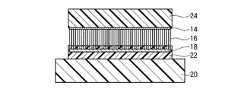
半導体素子58上には、半導体素子58を覆うように、半導体素子58からの熱を拡散するためのヒートスプレッダ62が形成されている。ヒートスプレッダ62は、例えば有機シーラント60によって回路基板54に接着されている。半導体素子58とヒートスプレッダ62との間には、本実施形態によるカーボンナノチューブシート10が形成されている。 A
このように、図1に示す電子機器では、半導体素子58とヒートスプレッダ62との間、すなわち発熱部と放熱部との間に、本実施形態によるカーボンナノチューブシート108が設けられている。 As described above, in the electronic apparatus shown in FIG. 1, the carbon nanotube sheet 108 according to the present embodiment is provided between the
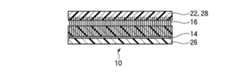
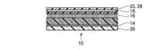
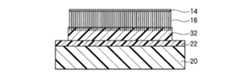
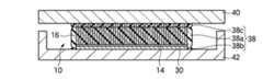
本実施形態によるカーボンナノチューブシート10は、図2(a)に示すように、シートの膜厚方向、すなわちシートの表面と交差する方向に配向した複数のカーボンナノチューブ16を有している。カーボンナノチューブ16の一端部側(図面において下側)には、カーボンナノチューブ16の間隙を埋め込むように充填層26が形成されている。カーボンナノチューブ16の他端部側(図面において上側)には、カーボンナノチューブ16の間隙を埋め込むように充填層28が形成されている。 As shown in FIG. 2A, the
カーボンナノチューブシート10は、例えば図2(b)に示すように、被着体40と被着体42との間に設けられ、被着体40と被着体42との間の熱伝導性や電気伝導性を向上するためのものである。被着体40,42は、例えば、発熱体(例えば、LSIチップ)や放熱体(例えば、ヒートスプレッダ)である。図1に示す電子機器の例では、発熱体は半導体素子106であり、放熱体はヒートスプレッダ110である。被着体40と被着体42との間に設けられる際、カーボンナノチューブシート10の充填層26,28は、被着体40,42の表面凹凸に応じて形状変化し、カーボンナノチューブシート10と被着体40,42との間の密着性を向上する。この形状変化に伴い、カーボンナノチューブ16の端部は、被着体40,42に接触される。 For example, as shown in FIG. 2B, the
カーボンナノチューブ16は、単層カーボンナノチューブ及び多層カーボンナノチューブのいずれでもよい。カーボンナノチューブ16の面密度は、特に限定されるものではないが、放熱性及び電気伝導性の観点からは、1×10¹⁰本/cm2以上の平面密度であることが望ましい。後述の製造方法を用いることにより、成長時の面密度を超えた高い面密度でカーボンナノチューブ16を形成することができる。The
カーボンナノチューブ12の長さ(シートの厚さ)は、カーボンナノチューブシート10の用途によって決まり、特に限定されるものではないが、好ましくは5μm〜500μm程度の値に設定することができる。 The length (sheet thickness) of the
充填層26,28は、カーボンナノチューブシート10を被着体40,42と接触した後にリフローが可能な材料であり、例えば、熱可塑性樹脂材料を用いることができる。なお、充填層26,28の具体的な構成材料については、後述する製造方法の説明の中で述べる。 The filling layers 26 and 28 are materials that can be reflowed after the
図2(a)において、充填層26と充填層28とが直に接していないが、充填層26と充填層28とは直に接していてもよい。また、充填層26,28は、必ずしもカーボンナノチューブ16の両端部に設ける必要はなく、充填層26,28の一方(例えば充填層26)だけを設けるようにしてもよい。 In FIG. 2A, the filling
次に、本実施形態によるカーボンナノチューブシートの製造方法について図3乃至図10を用いて説明する。 Next, the method for manufacturing the carbon nanotube sheet according to the present embodiment will be explained with reference to FIGS.
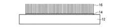
まず、カーボンナノチューブを形成するための土台として用いる基板12を用意する。基板12は、特に限定されるものではないが、シリコン基板などの半導体基板、アルミナ(サファイア)基板、MgO基板、ガラス基板などの絶縁体基板等を用いることができる。また、これら基板上に薄膜が形成されたものでもよい。例えば、シリコン基板上に膜厚300nm程度のシリコン酸化膜が形成されたものを用いることができる。 First, a
基板12はカーボンナノチューブの形成後に剥離されるものである。この目的のもと、基板12としては、カーボンナノチューブの形成温度において、変質しないこと、少なくともカーボンナノチューブに接する面が、カーボンナノチューブから容易に剥離できる材料によって構成されていること、又はカーボンナノチューブに対して選択的にエッチングできる材料によって構成されていることが望ましい。 The
次いで、基板12上に、例えばスパッタ法により、例えばFe(鉄)を堆積し、例えば膜厚2.5nmのFe膜の触媒金属膜14を形成する。 Next, for example, Fe (iron) is deposited on the
触媒金属膜14は、基板12上の全面に形成するようにしてもよいし、基板12上の特定の領域に選択的に形成するようにしてもよい。触媒金属膜14を基板12上の特定の領域に選択的に形成するには、メタルマスクを用いて触媒金属を堆積する方法や、フォトレジスト膜を用いたリフトオフ法等を適用することができる。触媒金属膜14の配置は、カーボンナノチューブシートの用途等に応じて適宜設定することができる。 The
触媒金属膜14を形成するための触媒金属としては、Feのほか、Co(コバルト)、Ni(ニッケル)、Au(金)、Ag(銀)、Pt(白金)又はこれらのうち少なくとも一の材料を含む合金を用いてもよい。触媒として、金属膜以外に微分型静電分級器(DMA:differential mobility analyzer)等を用い、あらかじめサイズを制御して作製した金属微粒子を用いてもよい。この場合も、金属種については薄膜と同様でよい。また、これら触媒金属の下地膜として、Mo(モリブデン)、Ti(チタン)、Hf(ハフニウム)、Zr(ジルコニウム)、Nb(ニオブ)、V(バナジウム)、TaN(窒化タンタル)、TiSix(チタンシリサイド)、Al(アルミニウム)、Al2O3(酸化アルミニウム)、TiOx(酸化チタン)、Ta(タンタル)、W(タングステン)、Cu(銅)、Au(金)、Pt(白金)、Pd(パラジウム)、若しくはTiN(チタンナイトライド)の膜、又はこれらのうち少なくとも一の材料を含む合金の膜を形成してもよい。例えば、Fe(2.5nm)/Al(10nm)の積層構造、Co(2.6nm)/TiN(5nm)の積層構造等を適用することができる。金属微粒子を用いる場合は、例えばCo(平均直径3.8nm)/TiN(5nm)の積層構造を適用することができる。As the catalyst metal for forming the
次いで、触媒金属膜14を形成した基板12上に、例えばホットフィラメントCVD法により、触媒金属膜14を触媒としてカーボンナノチューブ16を成長する。カーボンナノチューブ16の成長条件は、例えば、原料ガスとしてアセチレン・アルゴンの混合ガス(分圧比1:9)を用い、成膜室内の総ガス圧を1kPa、ホットフィラメント温度を1000℃、成長時間を20分とする。これにより、層数が3〜6層(平均4層程度)、直径が4〜8nm(平均6nm)、長さが80μm(成長レート:4μm/min)の多層カーボンナノチューブ16を成長することができる。 Next,
カーボンナノチューブ16は、熱CVD法やリモートプラズマCVD法などの他の成膜方法により形成してもよい。また、成長するカーボンナノチューブ14は、単層カーボンナノチューブでもよい。また、炭素原料としては、アセチレンのほか、メタン、エチレン等の炭化水素類や、エタノール、メタノール等のアルコール類などを用いてもよい。 The
こうして、基板12の触媒金属膜14が形成された領域上に、基板12の表面に対して垂直方向に配向した複数のカーボンナノチューブ16を形成する(図3)。なお、上記の成長条件で形成したカーボンナノチューブ16では、面密度は、1×10¹¹本/cm2程度であった。Thus, a plurality of
なお、基板12上にカーボンナノチューブ16を形成する方法は、上記の方法に限定されるものではない。例えば、基板12とは異なる他の基板上に形成したカーボンナノチューブを、接着剤等を用いて基板12上に転写するようにしてもよい。 The method for forming the
次いで、基板12とは別に、熱収縮性を有する基板(熱収縮性シート)20を用意し、この熱収縮性シート20上に接着剤を塗布する。 Next, apart from the
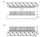
次いで、接着剤22を塗布した熱収縮性シート20をカーボンナノチューブ16上に熱圧着し、カーボンナノチューブ16上に熱収縮性シート20を接着剤22によって接着する(図4(a))。 Next, the heat-
熱収縮性を有する基板20は、加熱により収縮するものであれば特に限定されるものではなく、例えば、ポリ系合成樹脂シートなどの熱収縮性シートを適用することができる。ポリ系合成樹脂シートとしては、特に限定されるものではないが、例えば、株式会社トーヨー製「こうさくプラバン」、株式会社チクマプランニングシステム製「シュリンクシート」等が挙げられる。これら製品の熱収縮温度は、140℃〜150℃程度である。 The heat-
接着剤22は、カーボンナノチューブ16を熱収縮性シート20に接着できるものであり、融点が熱収縮性シート20の熱収縮温度よりも低いものであれば、特に限定されるものではない。接着剤22としては、例えば、ホットメルトワックス、水溶性糊、フォトレジスト等を適用することができる。ホットメルトワックスとしては、例えば、有限会社サンユウテクノ製「WT050T」(融点50℃)、SONNEBORN社製「W445」(融点60℃)等が挙げられる。水溶性糊としては、ポリビニルアルコールが挙げられる。 The adhesive 22 is not particularly limited as long as it can adhere the
次いで、熱収縮性シート20を、カーボンナノチューブ16とともに基板12から剥離する。これにより、カーボンナノチューブ16は、熱収縮性シート20側に転写される(図4(b))。 Next, the heat-
なお、本実施形態の一部の図面には、カーボンナノチューブ16の端部に触媒金属膜14が形成されている状態が示されている。触媒金属膜14は、カーボンナノチューブ16の成長の際に凝集化してカーボンナノチューブ内に取り込まれるため、実際には図示するような状態で残存してはおらず、シートの下面にはカーボンナノチューブ12が露出する。また、触媒金属膜14は、基板12を剥離する際に同時に除去されることもある。 A part of the drawings of this embodiment shows a state in which the
次いで、カーボンナノチューブ16を転写した熱収縮性シート20を、周囲から熱が均等に加わる加熱装置、例えば電気炉で、熱収縮性シート20の熱収縮温度よりも高い温度、例えば140℃で加熱する。 Next, the heat-
この熱処理により、熱収縮性シート20は収縮し、カーボンナノチューブ16が形成された領域も、熱収縮性シート20と同様に収縮する。結果として、カーボンナノチューブ16が形成された面積は元の面積に比べて約1/4〜1/6程度となり、面密度は約4〜6倍となる(図5)。 By this heat treatment, the heat-
この際、接着剤22の融点は熱収縮性シート20の収縮温度よりも低いため、熱収縮性シート20の熱収縮の際に接着剤22は溶解している。したがって、接着剤22が熱収縮性シート20の熱収縮を阻害することはない。また、溶解した接着剤22は、粘性を有しており、熱収縮性シート20の収縮の際に配向性を保持したままカーボンナノチューブ16を支持する役割をも果たす。 At this time, since the melting point of the adhesive 22 is lower than the contraction temperature of the heat-
次いで、カーボンナノチューブ16上に、熱可塑性樹脂フィルム24を載置する(図6)。熱可塑性樹脂フィルム24は、充填層26となるものである。 Next, the
熱可塑性樹脂フィルム24を形成する熱可塑性樹脂材料は、特に限定されるものではないが、例えば、以下に示すホットメルト樹脂を適用することができる。ポリアミド系ホットメルト樹脂としては、例えば、ヘンケルジャパン株式会社製の「Micromelt6239」(軟化点温度:140℃)、日本マタイ株式会社製の「エルファンOH501」(融点:80℃)、日本マタイ株式会社製の「エルファンNT120」(融点:120℃)が挙げられる。また、ポリエステル系ホットメルト樹脂としては、例えば、ノガワケミカル株式会社の「DH598B」(軟化点温度:133℃)が挙げられる。また、ポリウレタン系ホットメルト樹脂としては、例えば、ノガワケミカル株式会社製の「DH722B」が挙げられる。また、ポリオレフィン系ホットメルト樹脂としては、例えば、松村石油株式会社製の「EP−90」(軟化点温度:148℃)が挙げられる。また、エチレン共重合体ホットメルト樹脂としては、例えば、ノガワケミカル株式会社製の「DA574B」(軟化点温度:105℃)が挙げられる。また、SBR系ホットメルト樹脂としては、例えば、横浜ゴム株式会社製の「M−6250」(軟化点温度:125℃)が挙げられる。また、EVA系ホットメルト樹脂としては、例えば、住友スリーエム株式会社製の「3747」(軟化点温度:104℃)が挙げられる。また、ブチルゴム系ホットメルト樹脂としては、例えば、横浜ゴム株式会社製の「M−6158」が挙げられる。なお、軟化点温度は柔軟性が出てくる温度であり、融点は溶け始める温度である。 Although the thermoplastic resin material which forms the
熱可塑性樹脂フィルム24を形成する熱可塑性樹脂材料は、軟化温度が接着剤22の融点よりも高いこと、又は、接着剤22の溶剤に対する耐性があることが望ましい。 The thermoplastic resin material forming the
次いで、熱可塑性樹脂フィルム24を形成する熱可塑性樹脂材料の軟化温度よりも高い温度で加熱し、溶解した熱可塑性樹脂材料をカーボンナノチューブ16間に浸透させ、充填層26を形成する(図7)。熱可塑性樹脂フィルム24として例えば日本マタイ株式会社製の「エルファンNT120」を用いた場合には、例えば120℃で加熱することにより、熱可塑性樹脂フィルム24を浸透させることができる。 Next, heating is performed at a temperature higher than the softening temperature of the thermoplastic resin material forming the
次いで、接着剤22を溶解して熱収縮性シート20をカーボンナノチューブ16から剥離し、本実施形態によるカーボンナノチューブシート10を得る(図8)。 Next, the adhesive 22 is dissolved and the heat-
接着剤22としてホットメルトワックスを用いた場合には、例えば、ホットメルトワックスの融点よりも高く充填層26の熱可塑性樹脂材料の軟化温度よりも低い温度で熱処理を行ってホットメルトワックスを溶解することにより、熱収縮性シート20を剥離する。接着剤として水溶性糊を用いた場合には、例えば、充填層26の熱可塑性樹脂材料の軟化温度よりも低い温度の高温水蒸気を噴霧して水溶性糊を溶解することにより、熱収縮性シート20を剥離する。 When hot melt wax is used as the adhesive 22, for example, heat treatment is performed at a temperature higher than the melting point of the hot melt wax and lower than the softening temperature of the thermoplastic resin material of the
接着剤22として例えばSONNEBORN社製の「W445」を用いた場合には、例えば60℃で加熱することにより、熱収縮性シート20をカーボンナノチューブ16から剥離することができる。 For example, when “W445” manufactured by SONNEBORN is used as the adhesive 22, the heat-
接着剤22と充填層26とのエッチング特性が異なる場合には、接着剤22を、充填層26にダメージを与えることなく選択的にエッチングすることができる。 When the etching characteristics of the adhesive 22 and the
接着剤22は、必ずしも完全に除去する必要はなく、例えば図8に示すように、カーボンナノチューブ16間に残存してもよい。残存した接着剤22は、充填層28として用いることができる。接着剤22は、総て除去するようにしてもよい。 The adhesive 22 does not necessarily need to be completely removed, and may remain between the
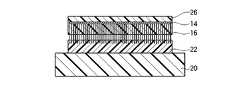
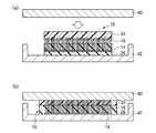
次いで、上述のようにして形成したカーボンナノチューブシート10を、LSIチップ40とヒートスプレッダ42との間に設置し、充填層26,28の軟化温度よりも高い温度で加熱圧着する(図9(a))。 Next, the
この熱処理により、充填層26,28が軟化し、LSIチップ40及びヒートスプレッダ42の表面凹凸に沿ってカーボンナノチューブシート10が変形する。また、カーボンナノチューブシート10内のカーボンナノチューブ16は、充填層26,28による拘束がゆるみ、その端部はLSIチップ40及びヒートスプレッダ42に直に接するようになる。この際、カーボンナノチューブ16はしなやかで柔軟性に富んだ材料であるため、LSIチップ40及びヒートスプレッダ42が有する凹凸形状に追従して撓むことができる。これにより、LSIチップ40及びヒートスプレッダ42に直に接するカーボンナノチューブ16が増加し、カーボンナノチューブシート10とLSIチップ40及びヒートスプレッダ42との間の接触熱抵抗を大幅に低減することができる(図9(b))。 By this heat treatment, the filling layers 26 and 28 are softened, and the
特に、本実施形態によるカーボンナノチューブシートの製造方法を用いることにより、成長時の面密度を超えた高い面密度でカーボンナノチューブ16を形成することができる。これにより、カーボンナノチューブシート10の熱伝導性及び導電性を大幅に向上することができる。 In particular, by using the carbon nanotube sheet manufacturing method according to the present embodiment, the
次いで、室温まで冷却し、充填層26、28を固化する。この際、充填層26を形成する熱可塑性樹脂及び充填層28を形成する接着剤22は接着性を発現し、LSIチップ40とヒートスプレッダ42との間をカーボンナノチューブシート10によって接着固定することができる。これにより、室温に冷却した後も、カーボンナノチューブシート10とLSIチップ42及びヒートスプレッダ44との間の低い接触熱抵抗を維持することができる。 Subsequently, it cools to room temperature and solidifies the filling layers 26 and 28. At this time, the thermoplastic resin forming the
このように、本実施形態によれば、熱収縮性を有する基板上にカーボンナノチューブを形成し、基板を熱収縮した後に充填層を形成してシート化するので、成長時の面密度を超えた高い面密度で形成されたカーボンナノチューブを有するカーボンナノチューブシートを製造することができる。これにより、カーボンナノチューブシートの熱伝導性及び導電性を大幅に向上することができる。 As described above, according to the present embodiment, the carbon nanotubes are formed on the heat-shrinkable substrate, the filling layer is formed after the substrate is heat-shrinked, and the sheet is formed, so that the surface density at the time of growth was exceeded. A carbon nanotube sheet having carbon nanotubes formed with a high surface density can be manufactured. Thereby, the thermal conductivity and conductivity of the carbon nanotube sheet can be greatly improved.
また、カーボンナノチューブを支持する充填層の材料として熱可塑性樹脂を用いることにより、充填層のリフローが可能であり被着体に対する接触熱抵抗及び接触抵抗の小さいカーボンナノチューブシートを容易に形成することができる。 In addition, by using a thermoplastic resin as a material for the filling layer that supports the carbon nanotubes, it is possible to reflow the filling layer and easily form a carbon nanotube sheet with low contact thermal resistance and contact resistance to the adherend. it can.
[第2実施形態]
第2実施形態によるカーボンナノチューブシート及びその製造方法について図10乃至図16を用いて説明する。なお、図1乃至図9に示す第1実施形態によるカーボンナノチューブシート及びその製造方法と同様の構成要素には同一の符号を付し説明を省略し又は簡潔にする。[Second Embodiment]
The carbon nanotube sheet and the manufacturing method thereof according to the second embodiment will be described with reference to FIGS. Components similar to those of the carbon nanotube sheet and the manufacturing method thereof according to the first embodiment shown in FIGS. 1 to 9 are denoted by the same reference numerals, and description thereof is omitted or simplified.
図10は、本実施形態によるカーボンナノチューブシートの構造を示す概略断面図である。図11乃至図16は、本実施形態によるカーボンナノチューブシートの製造方法を示す工程断面図である。 FIG. 10 is a schematic cross-sectional view showing the structure of the carbon nanotube sheet according to the present embodiment. 11 to 16 are process cross-sectional views illustrating the method of manufacturing the carbon nanotube sheet according to the present embodiment.
はじめに、本実施形態によるカーボンナノチューブシートの構造について図10を用いて説明する。 First, the structure of the carbon nanotube sheet according to the present embodiment will be explained with reference to FIG.
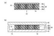
本実施形態によるカーボンナノチューブシートは、図10に示すように、カーボンナノチューブ16の充填層28側の端部に、被膜18が形成されているほかは、図2に示す第1実施形態によるカーボンナノチューブシートと同様である。 As shown in FIG. 10, the carbon nanotube sheet according to the present embodiment is the same as the carbon nanotube according to the first embodiment shown in FIG. 2, except that the
被膜18を形成する材料は、充填層26,28の構成材料よりも熱伝導率の高い材料であれば、特に限定されるものではない。 The material for forming the
熱伝導性の高い被膜18を設けることにより、被膜18を設けない場合と比較して、カーボンナノチューブシート10の被着体(例えば、放熱体や発熱体)に対する接触面積を増加することができる。これにより、カーボンナノチューブ16と被着体との間の接触熱抵抗が低減され、カーボンナノチューブシート10の熱伝導性を高めることができる。カーボンナノチューブシート10を導電性シートとしても用いる場合には、導電性を高めることができる。 By providing the
次に、本実施形態によるカーボンナノチューブシートの製造方法について図11乃至図16を用いて説明する。 Next, the method for manufacturing the carbon nanotube sheet according to the present embodiment will be explained with reference to FIGS.
まず、図3に示す第1実施形態によるカーボンナノチューブシートの製造方法と同様にして、基板12上に、カーボンナノチューブ16を成長する。 First, the
次いで、カーボンナノチューブ16上に、例えば蒸着法により、例えば膜厚数百nmのAuを形成し、Auの被膜18を形成する。 Next, Au having a film thickness of, for example, several hundreds of nanometers is formed on the
被膜18を形成する材料は、充填層26,28の構成材料よりも熱伝導率の高い材料であれば特に限定されるものではない。カーボンナノチューブシート10を電気伝導用途にも用いる場合には、導電性を有する材料、例えば、金属や合金等を適用することができる。被膜16の構成材料としては、例えば、銅(Cu)、ニッケル(Ni)、金(Au)等を用いることができる。また、被膜18は、単層構造である必要はなく、例えばチタン(Ti)と金(Au)との積層構造など、2層或いは3層以上の積層構造であってもよい。 The material for forming the
被膜18の膜厚は、接着剤22の浸透性、カーボンナノチューブシート10に要求される特性、被膜18の構成材料等に応じて適宜設定することが望ましい。 The film thickness of the
被膜18は、成長初期段階では、例えば図61(a)に示すように、各カーボンナノチューブ16の先端部分を覆うように形成される。成長膜厚が増加してくると、隣接する各カーボンナノチューブ16の先端部分に形成された被膜18が互いに接続される。これにより、被膜18は、例えば図61(b)に示すように、複数本の各カーボンナノチューブ16の先端部分を束ねるように形成される。被膜18の成長膜厚を更に増加すると、被膜18がシートの面に平行な2次元方向に完全に接続され、隙間のない完全な膜となる。後工程において接着剤22の浸透性を維持するためには、被膜18が完全な膜とならないように膜厚を制御することが望ましい。 In the initial stage of growth, the
次いで、被膜18を形成したカーボンナノチューブ16上に、図4(a)に示す第1実施形態によるカーボンナノチューブシートの製造方法と同様にして、熱収縮性シート20を接着する(図11(a))。 Next, the heat-
次いで、熱収縮性シート20を、カーボンナノチューブ16とともに基板12から剥離する。これにより、カーボンナノチューブ16は、熱収縮性シート20側に転写される(図11(b))。 Next, the heat-
次いで、上下から均等に熱が加わる加熱装置を用いて熱収縮性シート20を収縮させる。この熱処理により、熱収縮性シート20は収縮し、カーボンナノチューブ16が形成された領域も、熱収縮性シート20と同様に収縮する。結果として、カーボンナノチューブ16が形成された面積は元の面積に比べて約1/4程度となり、面密度は約4倍となる(図12)。 Next, the heat-
次いで、カーボンナノチューブ16上に、熱可塑性樹脂フィルム24を載置する(図13)。 Next, the
次いで、熱可塑性樹脂フィルム24を形成する熱可塑性樹脂材料の軟化温度よりも高い温度で加熱し、溶解した熱可塑性樹脂材料をカーボンナノチューブ16間に浸透させ、充填層26を形成する(図14)。 Next, heating is performed at a temperature higher than the softening temperature of the thermoplastic resin material forming the
次いで、接着剤22を溶解して熱収縮性シート20をカーボンナノチューブ16から剥離し、本実施形態によるカーボンナノチューブシート10を得る(図15)。 Next, the adhesive 22 is dissolved, and the heat-
次いで、上述のようにして形成したカーボンナノチューブシート10を、LSIチップ40とヒートスプレッダ42との間に設置し、充填層26,28の軟化温度よりも高い温度で加熱圧着する(図16(a))。これにより、圧着時に充填層26,28が液化し、端部のカーボンナノチューブ16のバネ性が得られる構造となる。 Next, the
次いで、室温まで冷却し、充填層26、28を固化する(図16(b))。これにより、室温に冷却した後も、カーボンナノチューブシート10とLSIチップ42及びヒートスプレッダ44との間の低い接触熱抵抗を維持することができる。 Subsequently, it cools to room temperature and solidifies the filling layers 26 and 28 (FIG.16 (b)). Thereby, even after cooling to room temperature, a low contact thermal resistance between the
このように、本実施形態によれば、カーボンナノチューブの端部に熱伝導性の高い被膜を形成するので、被着体に対する接触熱抵抗及び接触抵抗を低減することができる。これにより、カーボンナノチューブシートの熱伝導性及び導電性を更に向上することができる。 Thus, according to this embodiment, since the coating film having high thermal conductivity is formed at the end of the carbon nanotube, the contact thermal resistance and the contact resistance with respect to the adherend can be reduced. Thereby, the thermal conductivity and conductivity of the carbon nanotube sheet can be further improved.
[第3実施形態]
第3実施形態によるカーボンナノチューブシート及びその製造方法について図17乃至図23を用いて説明する。なお、図1乃至図16に示す第1及び第2実施形態によるカーボンナノチューブシート及びその製造方法と同様の構成要素には同一の符号を付し説明を省略し又は簡潔にする。[Third Embodiment]
A carbon nanotube sheet and a manufacturing method thereof according to the third embodiment will be described with reference to FIGS. Components similar to those in the carbon nanotube sheet and the manufacturing method thereof according to the first and second embodiments shown in FIGS. 1 to 16 are denoted by the same reference numerals, and description thereof is omitted or simplified.
図17は、本実施形態によるカーボンナノチューブシートの構造を示す概略断面図である。図18乃至図23は、本実施形態によるカーボンナノチューブシートの製造方法を示す工程断面図である。 FIG. 17 is a schematic cross-sectional view showing the structure of the carbon nanotube sheet according to the present embodiment. 18 to 23 are process cross-sectional views illustrating the method of manufacturing the carbon nanotube sheet according to the present embodiment.
はじめに、本実施形態によるカーボンナノチューブシートの構造について図17を用いて説明する。 First, the structure of the carbon nanotube sheet according to the present embodiment will be explained with reference to FIG.
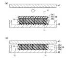
本実施形態によるカーボンナノチューブシートは、図17に示すように、カーボンナノチューブ16の充填層26側の端部に、被膜30が形成されているほかは、図2に示す第1実施形態によるカーボンナノチューブシートと同様である。 As shown in FIG. 17, the carbon nanotube sheet according to the present embodiment is the same as the carbon nanotube according to the first embodiment shown in FIG. 2 except that a
被膜30を形成する材料は、充填層26,28の構成材料よりも熱伝導率の高い材料であれば、特に限定されるものではない。被膜30には、第2実施形態において示した被膜18を形成するための材料と同様の材料を適用することができる。 The material for forming the
熱伝導性の高い被膜30を設けることにより、被膜30を設けない場合と比較して、カーボンナノチューブシート10の被着体(例えば、放熱体や発熱体)に対する接触面積を増加することができる。これにより、カーボンナノチューブ16と被着体との間の接触熱抵抗が低減され、カーボンナノチューブシート10の熱伝導性を高めることができる。カーボンナノチューブシート10を導電性シートとしても用いる場合には、導電性を高めることができる。 By providing the
次に、本実施形態によるカーボンナノチューブシートの製造方法について図18乃至図23を用いて説明する。 Next, the method for manufacturing the carbon nanotube sheet according to the present embodiment will be explained with reference to FIGS.
まず、図3に示す第1実施形態によるカーボンナノチューブシートの製造方法と同様にして、基板12上に、カーボンナノチューブ16を成長する。 First, the
次いで、図4(a)に示す第1実施形態によるカーボンナノチューブシートの製造方法と同様にして、カーボンナノチューブ16上に、熱収縮性シート20を接着する(図18(a))。 Next, the heat-
次いで、熱収縮性シート20を、カーボンナノチューブ16とともに基板12から剥離する。これにより、カーボンナノチューブ16は、熱収縮性シート20側に転写される(図18(b))。 Next, the heat-
次いで、上下から均等に熱が加わる加熱装置を用いて熱収縮性シート20を収縮させる。この熱処理により、熱収縮性シート20は収縮し、カーボンナノチューブ16が形成された領域も、熱収縮性シート20と同様に収縮する。結果として、カーボンナノチューブ16が形成された面積は元の面積に比べて約1/4程度となり、面密度は約4倍となる。 Next, the heat-
次いで、カーボンナノチューブ16上に、例えば蒸着法により、例えば膜厚数百nmのAuを形成し、Auの被膜30を形成する(図19)。 Next, on the
被膜30の膜厚は、後工程において熱可塑性樹脂フィルム24の浸透を阻害しない膜厚(被膜30が完全な膜とならない膜厚)であれば、特に限定されるものではない。被膜30の膜厚は、熱可塑性樹脂フィルム24の浸透性、カーボンナノチューブシート10に要求される特性、被膜30の構成材料等に応じて適宜設定することが望ましい。 The film thickness of the
次いで、被膜30を形成したカーボンナノチューブ16上に、熱可塑性樹脂フィルム24を載置する(図20)。 Next, the
次いで、熱可塑性樹脂フィルム24を形成する熱可塑性樹脂材料の軟化温度よりも高い温度で加熱し、溶解した熱可塑性樹脂材料をカーボンナノチューブ16間に浸透させ、充填層26を形成する(図21)。 Next, heating is performed at a temperature higher than the softening temperature of the thermoplastic resin material forming the
次いで、接着剤22を溶解して熱収縮性シート20をカーボンナノチューブ16から剥離し、本実施形態によるカーボンナノチューブシート10を得る(図22)。 Next, the adhesive 22 is dissolved and the heat-
次いで、上述のようにして形成したカーボンナノチューブシート10を、LSIチップ40とヒートスプレッダ42との間に設置し、充填層26,28の軟化温度よりも高い温度で加熱圧着する(図23(a))。これにより、圧着時に充填層26,28が液化し、端部のカーボンナノチューブ16のバネ性が得られる構造となる。 Next, the
次いで、室温まで冷却し、充填層26、28を固化する(図23(b))。これにより、室温に冷却した後も、カーボンナノチューブシート10とLSIチップ42及びヒートスプレッダ44との間の低い接触熱抵抗を維持することができる。 Subsequently, it cools to room temperature and solidifies the filling layers 26 and 28 (FIG.23 (b)). Thereby, even after cooling to room temperature, a low contact thermal resistance between the
このように、本実施形態によれば、カーボンナノチューブの端部に熱伝導性の高い被膜を形成するので、被着体に対する接触熱抵抗及び接触抵抗を低減することができる。これにより、カーボンナノチューブシートの熱伝導性及び導電性を更に向上することができる。 Thus, according to this embodiment, since the coating film having high thermal conductivity is formed at the end of the carbon nanotube, the contact thermal resistance and the contact resistance with respect to the adherend can be reduced. Thereby, the thermal conductivity and conductivity of the carbon nanotube sheet can be further improved.
[第4実施形態]
第4実施形態によるカーボンナノチューブシート及びその製造方法について図24乃至図30を用いて説明する。なお、図1乃至図23に示す第1乃至第3実施形態によるカーボンナノチューブシート及びその製造方法と同様の構成要素には同一の符号を付し説明を省略し又は簡潔にする。[Fourth Embodiment]
The carbon nanotube sheet and the manufacturing method thereof according to the fourth embodiment will be described with reference to FIGS. Components similar to those of the carbon nanotube sheet and the manufacturing method thereof according to the first to third embodiments shown in FIGS. 1 to 23 are denoted by the same reference numerals, and description thereof is omitted or simplified.
図24は、本実施形態によるカーボンナノチューブシートの構造を示す概略断面図である。図25乃至図30は、本実施形態によるカーボンナノチューブシートの製造方法を示す工程断面図である。 FIG. 24 is a schematic cross-sectional view showing the structure of the carbon nanotube sheet according to the present embodiment. 25 to 30 are process cross-sectional views illustrating the method of manufacturing the carbon nanotube sheet according to the present embodiment.
はじめに、本実施形態によるカーボンナノチューブシートの構造について図24を用いて説明する。 First, the structure of the carbon nanotube sheet according to the present embodiment will be explained with reference to FIG.
本実施形態によるカーボンナノチューブシートは、図24に示すように、カーボンナノチューブ16の両端部に、被膜18,30が形成されているほかは、図2に示す第1実施形態によるカーボンナノチューブシートと同様である。 The carbon nanotube sheet according to the present embodiment is the same as the carbon nanotube sheet according to the first embodiment shown in FIG. 2 except that the
熱伝導性の高い被膜18,30を設けることにより、被膜18,30を設けない場合と比較して、カーボンナノチューブシート10の被着体(例えば、放熱体や発熱体)に対する接触面積を増加することができる。これにより、カーボンナノチューブ16と被着体との間の接触熱抵抗が低減され、カーボンナノチューブシート10の熱伝導性を高めることができる。カーボンナノチューブシート10を導電性シートとしても用いる場合には、導電性を高めることができる。被膜18,30の一方を設ける場合と比較して、カーボンナノチューブ16と被着体との間の熱電導性及び導電性を更に高めることができる。 By providing the
次に、本実施形態によるカーボンナノチューブシートの製造方法について図25乃至図30を用いて説明する。 Next, the method for manufacturing the carbon nanotube sheet according to the present embodiment will be explained with reference to FIGS.
まず、図3に示す第1実施形態によるカーボンナノチューブシートの製造方法と同様にして、基板12上に、カーボンナノチューブ16を成長する。 First, the
次いで、例えば図11(a)に示す第2実施形態によるカーボンナノチューブシートの製造方法と同様にして、カーボンナノチューブ16上に、例えば蒸着法により、例えば膜厚数百nmのAuを形成し、Auの被膜18を形成する。 Next, for example, Au having a film thickness of several hundreds of nanometers is formed on the
次いで、被膜18を形成したカーボンナノチューブ16上に、図4(a)に示す第1実施形態によるカーボンナノチューブシートの製造方法と同様にして、熱収縮性シート20を接着する(図25(a))。 Next, the heat-
次いで、熱収縮性シート20を、カーボンナノチューブ16とともに基板12から剥離する。これにより、カーボンナノチューブ16は、熱収縮性シート20側に転写される(図25(b))。 Next, the heat-
次いで、上下から均等に熱が加わる加熱装置を用いて熱収縮性シート20を収縮させる。この熱処理により、熱収縮性シート20は収縮し、カーボンナノチューブ16が形成された領域も、熱収縮性シート20と同様に収縮する。結果として、カーボンナノチューブ16が形成された面積は元の面積に比べて約1/4程度となり、面密度は約4倍となる。 Next, the heat-
次いで、例えば図19に示す第3実施形態によるカーボンナノチューブシートの製造方法と同様にして、カーボンナノチューブ16上に、例えば蒸着法により、例えば膜厚数百nmのAuを形成し、Auの被膜30を形成する(図26)。 Next, for example, Au having a film thickness of several hundreds of nanometers is formed on the
次いで、被膜30を形成したカーボンナノチューブ16上に、熱可塑性樹脂フィルム24を載置する(図27)。 Next, the
次いで、熱可塑性樹脂フィルム24を形成する熱可塑性樹脂材料の軟化温度よりも高い温度で加熱し、溶解した熱可塑性樹脂材料をカーボンナノチューブ16間に浸透させ、充填層26を形成する(図28)。 Next, heating is performed at a temperature higher than the softening temperature of the thermoplastic resin material forming the
次いで、接着剤22を溶解して熱収縮性シート20をカーボンナノチューブ16から剥離し、本実施形態によるカーボンナノチューブシート10を得る(図29)。 Next, the adhesive 22 is dissolved and the heat-
次いで、上述のようにして形成したカーボンナノチューブシート10を、LSIチップ40とヒートスプレッダ42との間に設置し、充填層26,28の軟化温度よりも高い温度で加熱圧着する(図30(a))。これにより、圧着時に充填層26,28が液化し、端部のカーボンナノチューブ16のバネ性が得られる構造となる。 Next, the
次いで、室温まで冷却し、充填層26、28を固化する(図30(b))。これにより、室温に冷却した後も、カーボンナノチューブシート10とLSIチップ42及びヒートスプレッダ44との間の低い接触熱抵抗を維持することができる。 Subsequently, it cools to room temperature and solidifies the filling layers 26 and 28 (FIG.30 (b)). Thereby, even after cooling to room temperature, a low contact thermal resistance between the
このように、本実施形態によれば、カーボンナノチューブの端部に熱伝導性の高い被膜を形成するので、被着体に対する接触熱抵抗及び接触抵抗を低減することができる。これにより、カーボンナノチューブシートの熱伝導性及び導電性を更に向上することができる。 Thus, according to this embodiment, since the coating film having high thermal conductivity is formed at the end of the carbon nanotube, the contact thermal resistance and the contact resistance with respect to the adherend can be reduced. Thereby, the thermal conductivity and conductivity of the carbon nanotube sheet can be further improved.
[第5実施形態]
第5実施形態によるカーボンナノチューブシート及びその製造方法について図31乃至図37を用いて説明する。なお、図1乃至図30に示す第1乃至第4実施形態によるカーボンナノチューブシート及びその製造方法と同様の構成要素には同一の符号を付し説明を省略し又は簡潔にする。[Fifth Embodiment]
The carbon nanotube sheet and the manufacturing method thereof according to the fifth embodiment will be described with reference to FIGS. Components similar to those of the carbon nanotube sheet and the manufacturing method thereof according to the first to fourth embodiments shown in FIGS. 1 to 30 are denoted by the same reference numerals, and description thereof is omitted or simplified.
図31は、本実施形態によるカーボンナノチューブシートの構造を示す概略断面図である。図32乃至図37は、本実施形態によるカーボンナノチューブシートの製造方法を示す工程断面図である。 FIG. 31 is a schematic cross-sectional view showing the structure of the carbon nanotube sheet according to the present embodiment. 32 to 37 are process cross-sectional views illustrating the method of manufacturing the carbon nanotube sheet according to the present embodiment.
はじめに、本実施形態によるカーボンナノチューブシートの構造について図31を用いて説明する。 First, the structure of the carbon nanotube sheet according to the present embodiment will be explained with reference to FIG.
本実施形態によるカーボンナノチューブシートは、図31に示すように、充填層28の代わりに充填層34が形成されているほかは、図2に示す第1実施形態によるカーボンナノチューブシートと同様である。 The carbon nanotube sheet according to this embodiment is the same as the carbon nanotube sheet according to the first embodiment shown in FIG. 2 except that a
充填層34は、充填層26と同様、カーボンナノチューブシート10を被着体40,42と接触した後にリフローが可能な材料であり、例えば、熱可塑性樹脂材料を用いることができる。なお、充填層34の具体的な構成材料については、後述する製造方法の説明の中で述べる。 The filling
図31(a)において、充填層26と充填層34とが直に接していないが、充填層26と充填層34とは直に接していてもよい。 In FIG. 31A, the filling
次に、本実施形態によるカーボンナノチューブシートの製造方法について図32乃至図37を用いて説明する。 Next, the method for manufacturing the carbon nanotube sheet according to the present embodiment will be explained with reference to FIGS.
まず、図3に示す第1実施形態によるカーボンナノチューブシートの製造方法と同様にして、基板12上に、カーボンナノチューブ16を成長する。 First, the
次いで、熱収縮性シート20上に、接着剤22を形成する。 Next, an adhesive 22 is formed on the heat-
接着剤22は、融点が、後述する熱可塑性樹脂層32の溶解温度よりも低いものであれば、特に限定されるものではない。接着剤22としては、例えば、ホットメルトワックスや水溶性糊を適用することができる。ホットメルトワックスとしては、例えば、有限会社サンユウテクノ製「WT050T」(融点50℃)、SONNEBORN社製「W445」(融点60℃)等が挙げられる。水溶性糊としては、ポリビニルアルコールが挙げられる。 The adhesive 22 is not particularly limited as long as the melting point is lower than the melting temperature of the
次いで、接着剤22を形成した熱収縮性シート20上に、熱可塑性樹脂層32を形成する。 Next, a
熱可塑性樹脂層32は、充填層34となるものである。熱可塑性樹脂層32を形成する樹脂材料は、熱収縮性シート20の熱収縮温度よりも軟化温度が低いものであれば特に限定されるものではなく、例えば、充填層26を形成する熱可塑性樹脂材料と同様のホットメルト樹脂を適用することができる。熱収縮性シート20として熱収縮温度が140〜150℃程度の材料を用いる場合には、熱可塑性樹脂層32の樹脂材料として、例えば、日本マタイ株式会社製の「エルファンOH501」や「エルファンNT120」等を適用することができる。 The
次いで、接着剤22及び熱可塑性樹脂層32が形成された熱収縮性シート20をカーボンナノチューブ16上に熱圧着する(図32(a))。これにより、熱可塑性樹脂層32がカーボンナノチューブ16の上端部に浸透し、熱可塑性樹脂層32とカーボンナノチューブ16とが接着される。 Next, the heat-
次いで、熱収縮性シート20を、カーボンナノチューブ16とともに基板12から剥離する。これにより、カーボンナノチューブ16は、熱収縮性シート20側に転写される(図32(b))。 Next, the heat-
なお、前述の充填層26の形成方法と同様にして、熱可塑性樹脂材料をカーボンナノチューブ16の上端部に浸透させた後、その上に接着剤22を塗布した熱収縮性シート20を接着するようにしてもよい。 In the same manner as in the method for forming the
次いで、上下から均等に熱が加わる加熱装置を用い、熱収縮性シート20の熱収縮温度よりも高い温度、例えば140℃で加熱して、熱収縮性シート20を収縮させる。 Next, using a heating device that uniformly applies heat from above and below, the heat-
この熱処理により、熱収縮性シート20は収縮し、カーボンナノチューブ16が形成された領域も、熱収縮性シート20と同様に収縮する。結果として、カーボンナノチューブ16が形成された面積は元の面積に比べて約1/4程度となり、面密度は約4倍となる(図33)。 By this heat treatment, the heat-
この際、接着剤22及び熱可塑性樹脂層32の融点は熱収縮性シート20の収縮温度よりも低いため、熱収縮性シート20の熱収縮の際に接着剤22及び熱可塑性樹脂層32は溶解している。したがって、接着剤22及び熱可塑性樹脂層32が熱収縮性シート20の熱収縮を阻害することはない。また、溶解した熱可塑性樹脂層32は、粘性を有しており、熱収縮性シート20の収縮の際に配向性を保持したままカーボンナノチューブ16を支持する役割をも果たす。 At this time, since the melting points of the adhesive 22 and the
次いで、カーボンナノチューブ16上に、熱可塑性樹脂フィルム24を載置する(図134)。熱可塑性樹脂フィルム24は、充填層26となるものである。 Next, the
次いで、熱可塑性樹脂フィルム24を形成する熱可塑性樹脂材料の軟化温度よりも高い温度で加熱し、溶解した熱可塑性樹脂材料をカーボンナノチューブ16間に浸透させ、充填層26を形成する(図35)。熱可塑性樹脂フィルム24として例えば日本マタイ株式会社製の「エルファンNT120」を用いた場合には、例えば120℃で加熱することにより、熱可塑性樹脂フィルム24を浸透させることができる。 Next, heating is performed at a temperature higher than the softening temperature of the thermoplastic resin material forming the
次いで、接着剤22を溶解して熱収縮性シート20をカーボンナノチューブ16から剥離し、本実施形態によるカーボンナノチューブシート10を得る(図36)。熱可塑性樹脂層32は、充填層34としてカーボンナノチューブ16の端部に残存する。 Next, the adhesive 22 is dissolved and the heat-
接着剤22としてホットメルトワックスを用いた場合には、例えば、ホットメルトワックスの融点よりも高く充填層26の熱可塑性樹脂材料の軟化温度よりも低い温度で熱処理を行ってホットメルトワックスを溶解することにより、熱収縮性シート20を剥離する。接着剤として水溶性糊を用いた場合には、例えば、充填層26の熱可塑性樹脂材料の軟化温度よりも低い温度の高温水蒸気を噴霧して水溶性糊を溶解することにより、熱収縮性シート20を剥離する。 When hot melt wax is used as the adhesive 22, for example, heat treatment is performed at a temperature higher than the melting point of the hot melt wax and lower than the softening temperature of the thermoplastic resin material of the
接着剤22として例えば有限会社サンユウテクノ製「WT050T」を用いた場合には、例えば60℃〜70℃の湯で処理することにより、熱収縮性シート20をカーボンナノチューブ16から剥離することができる。 For example, when “WT050T” manufactured by Sanyu Techno Co., Ltd. is used as the adhesive 22, the heat-
次いで、上述のようにして形成したカーボンナノチューブシート10を、LSIチップ40とヒートスプレッダ42との間に設置し、充填層26,34の軟化温度よりも高い温度で加熱圧着する(図37(a))。これにより、圧着時に充填層26,34が液化し、端部のカーボンナノチューブ16のバネ性が得られる構造となる。 Next, the
次いで、室温まで冷却し、充填層26、34を固化する(図37(b))。これにより、室温に冷却した後も、カーボンナノチューブシート10とLSIチップ42及びヒートスプレッダ44との間の低い接触熱抵抗を維持することができる。 Subsequently, it cools to room temperature and solidifies the filling layers 26 and 34 (FIG. 37 (b)). Thereby, even after cooling to room temperature, a low contact thermal resistance between the
このように、本実施形態によれば、熱収縮性を有する基板上にカーボンナノチューブを形成し、基板を熱収縮した後に充填層を形成してシート化するので、成長時の面密度を超えた高い面密度で形成されたカーボンナノチューブを有するカーボンナノチューブシートを製造することができる。これにより、カーボンナノチューブシートの熱伝導性及び導電性を大幅に向上することができる。 As described above, according to the present embodiment, the carbon nanotubes are formed on the heat-shrinkable substrate, the filling layer is formed after the substrate is heat-shrinked, and the sheet is formed, so that the surface density at the time of growth was exceeded. A carbon nanotube sheet having carbon nanotubes formed with a high surface density can be manufactured. Thereby, the thermal conductivity and conductivity of the carbon nanotube sheet can be greatly improved.
また、カーボンナノチューブを支持する充填層の材料として熱可塑性樹脂を用いることにより、充填層のリフローが可能であり被着体に対する接触熱抵抗及び接触抵抗の小さいカーボンナノチューブシートを容易に形成することができる。 In addition, by using a thermoplastic resin as a material for the filling layer that supports the carbon nanotubes, it is possible to reflow the filling layer and easily form a carbon nanotube sheet with low contact thermal resistance and contact resistance to the adherend. it can.
[第6実施形態]
第6実施形態によるカーボンナノチューブシート及びその製造方法について図38を用いて説明する。なお、図1乃至図37に示す第1乃至第5実施形態によるカーボンナノチューブシート及びその製造方法と同様の構成要素には同一の符号を付し説明を省略し又は簡潔にする。[Sixth Embodiment]
The carbon nanotube sheet and the manufacturing method thereof according to the sixth embodiment will be described with reference to FIG. In addition, the same code | symbol is attached | subjected to the component similar to the carbon nanotube sheet and its manufacturing method by 1st thru | or 5th embodiment shown in FIG. 1 thru | or FIG. 37, and description is abbreviate | omitted or simplified.
図38は、本実施形態によるカーボンナノチューブシートの構造を示す概略断面図である。 FIG. 38 is a schematic cross-sectional view showing the structure of the carbon nanotube sheet according to the present embodiment.
はじめに、本実施形態によるカーボンナノチューブシートの構造について図38を用いて説明する。 First, the structure of the carbon nanotube sheet according to the present embodiment will be explained with reference to FIG.
本実施形態によるカーボンナノチューブシートは、図38に示すように、カーボンナノチューブ16の充填層34側の端部に、被膜18が形成されているほかは、図31に示す第5実施形態によるカーボンナノチューブシートと同様である。 As shown in FIG. 38, the carbon nanotube sheet according to the present embodiment is the same as the carbon nanotube according to the fifth embodiment shown in FIG. 31 except that the
被膜18を形成する材料は、充填層26,34の構成材料よりも熱伝導率の高い材料であれば特に限定されるものではない。 The material for forming the
熱伝導性の高い被膜18を設けることにより、被膜18を設けない場合と比較して、カーボンナノチューブシート10の被着体(例えば、放熱体や発熱体)に対する接触面積を増加することができる。これにより、カーボンナノチューブ16と被着体との間の接触熱抵抗が低減され、カーボンナノチューブシート10の熱伝導性を高めることができる。カーボンナノチューブシート10を導電性シートとしても用いる場合には、導電性を高めることができる。 By providing the
次に、本実施形態によるカーボンナノチューブシートの製造方法について説明する。なお、本実施形態は、第5実施形態によるカーボンナノチューブシートにおいて、第2実施形態によるカーボンナノチューブシートと同様の手法により被膜18を形成するものである。ここでは、新たな図面を使用せず、これら実施形態の図面を参照して説明するものとする。 Next, the method for manufacturing the carbon nanotube sheet according to the present embodiment will be described. In the present embodiment, in the carbon nanotube sheet according to the fifth embodiment, the
まず、図3に示す第1実施形態によるカーボンナノチューブシートの製造方法と同様にして、基板12上に、カーボンナノチューブ16を成長する。 First, the
次いで、カーボンナノチューブ16上に、例えば蒸着法により、例えば膜厚数百nmのAuを形成し、Auの被膜18を形成する(図11(a)参照)。 Next, Au having a film thickness of, for example, several hundreds of nanometers is formed on the
被膜18を形成する材料は、充填層26,34の構成材料よりも熱伝導率の高い材料であれば特に限定されるものではない。 The material for forming the
被膜18の膜厚は、後工程において充填層34となる熱可塑性樹脂の浸透を阻害しない膜厚であれば、特に限定されるものではない。被膜30の膜厚は、充填層34の熱可塑性樹脂の浸透性、カーボンナノチューブシート10に要求される特性、被膜18の構成材料等に応じて適宜設定することが望ましい。 The film thickness of the
次いで、被膜18を形成したカーボンナノチューブ16上に、第5実施形態によるカーボンナノチューブシートの製造方法と同様にして、接着剤22及び熱可塑性樹脂層32が形成された熱収縮性シート20を熱圧着する(図32(a)参照)。これにより、熱可塑性樹脂層32がカーボンナノチューブ16の上端部に浸透し、熱可塑性樹脂層32とカーボンナノチューブ16とが接着される。 Next, the heat-
次いで、熱収縮性シート20を、カーボンナノチューブ16とともに基板12から剥離する。これにより、カーボンナノチューブ16は、熱収縮性シート20側に転写される(図32(b)参照)。 Next, the heat-
次いで、上下から均等に熱が加わる加熱装置を用いて熱収縮性シート20を収縮させる。この熱処理により、熱収縮性シート20は収縮し、カーボンナノチューブ16が形成された領域も、熱収縮性シート20と同様に収縮する。結果として、カーボンナノチューブ16が形成された面積は元の面積に比べて約1/4程度となり、面密度は約4倍となる(図33参照)。 Next, the heat-
次いで、カーボンナノチューブ16上に、熱可塑性樹脂フィルム24を載置する(図34参照)。 Next, the
次いで、熱可塑性樹脂フィルム24を形成する熱可塑性樹脂材料の軟化温度よりも高い温度で加熱し、溶解した熱可塑性樹脂材料をカーボンナノチューブ16間に浸透させ、充填層26を形成する(図35参照)。 Next, heating is performed at a temperature higher than the softening temperature of the thermoplastic resin material forming the
次いで、接着剤22を溶解して熱収縮性シート20をカーボンナノチューブ16から剥離し、本実施形態によるカーボンナノチューブシート10を得る(図36参照)。熱可塑性樹脂層32は、充填層34としてカーボンナノチューブ16の端部に残存する。 Next, the adhesive 22 is dissolved and the heat-
次いで、上述のようにして形成したカーボンナノチューブシート10を、LSIチップ40とヒートスプレッダ42との間に設置し、充填層26,34の軟化温度よりも高い温度で加熱圧着する(図37(a)参照)。これにより、圧着時に充填層26,34が液化し、端部のカーボンナノチューブ16のバネ性が得られる構造となる。 Next, the
次いで、室温まで冷却し、充填層26、34を固化する(図38)。これにより、室温に冷却した後も、カーボンナノチューブシート10とLSIチップ42及びヒートスプレッダ44との間の低い接触熱抵抗を維持することができる。 Subsequently, it cools to room temperature and solidifies the filling layers 26 and 34 (FIG. 38). Thereby, even after cooling to room temperature, a low contact thermal resistance between the
このように、本実施形態によれば、カーボンナノチューブの端部に熱伝導性の高い被膜を形成するので、被着体に対する接触熱抵抗及び接触抵抗を低減することができる。これにより、カーボンナノチューブシートの熱伝導性及び導電性を更に向上することができる。 Thus, according to this embodiment, since the coating film having high thermal conductivity is formed at the end of the carbon nanotube, the contact thermal resistance and the contact resistance with respect to the adherend can be reduced. Thereby, the thermal conductivity and conductivity of the carbon nanotube sheet can be further improved.
[第7実施形態]
第7実施形態によるカーボンナノチューブシート及びその製造方法について図39を用いて説明する。なお、図1乃至図38に示す第1乃至第6実施形態によるカーボンナノチューブシート及びその製造方法と同様の構成要素には同一の符号を付し説明を省略し又は簡潔にする。[Seventh Embodiment]
The carbon nanotube sheet and the manufacturing method thereof according to the seventh embodiment will be described with reference to FIG. In addition, the same code | symbol is attached | subjected to the component similar to the carbon nanotube sheet and its manufacturing method by 1st thru | or 6th Embodiment shown to FIG. 1 thru | or 38, and description is abbreviate | omitted or simplified.
図39は、本実施形態によるカーボンナノチューブシートの構造を示す概略断面図である。 FIG. 39 is a schematic cross-sectional view showing the structure of the carbon nanotube sheet according to the present embodiment.
はじめに、本実施形態によるカーボンナノチューブシートの構造について図39を用いて説明する。 First, the structure of the carbon nanotube sheet according to the present embodiment will be explained with reference to FIG.
本実施形態によるカーボンナノチューブシートは、図39に示すように、カーボンナノチューブ16の充填層26側の端部に、被膜30が形成されているほかは、図31に示す第5実施形態によるカーボンナノチューブシートと同様である。 As shown in FIG. 39, the carbon nanotube sheet according to the present embodiment has the same structure as that of the carbon nanotube according to the fifth embodiment shown in FIG. 31 except that a
被膜30を形成する材料は、充填層26,34の構成材料よりも熱伝導率の高い材料であれば特に限定されるものではない。 The material for forming the
熱伝導性の高い被膜18を設けることにより、被膜18を設けない場合と比較して、カーボンナノチューブシート10の被着体(例えば、放熱体や発熱体)に対する接触面積を増加することができる。これにより、カーボンナノチューブ16と被着体との間の接触熱抵抗が低減され、カーボンナノチューブシート10の熱伝導性を高めることができる。カーボンナノチューブシート10を導電性シートとしても用いる場合には、導電性を高めることができる。 By providing the
次に、本実施形態によるカーボンナノチューブシートの製造方法について説明する。なお、本実施形態は、第5実施形態によるカーボンナノチューブシートにおいて、第3実施形態によるカーボンナノチューブシートと同様の手法により被膜18を形成するものである。ここでは、新たな図面を使用せず、これら実施形態の図面を参照して説明するものとする。 Next, the method for manufacturing the carbon nanotube sheet according to the present embodiment will be described. In the present embodiment, the
まず、図3に示す第1実施形態によるカーボンナノチューブシートの製造方法と同様にして、基板12上に、カーボンナノチューブ16を成長する。 First, the
次いで、カーボンナノチューブ16上に、第5実施形態によるカーボンナノチューブシートの製造方法と同様にして、接着剤22及び熱可塑性樹脂層32が形成された熱収縮性シート20を熱圧着する(図32(a)参照)。これにより、熱可塑性樹脂層32がカーボンナノチューブ16の上端部に浸透し、熱可塑性樹脂層32とカーボンナノチューブ16とが接着される。 Next, the heat-
次いで、熱収縮性シート20を、カーボンナノチューブ16とともに基板12から剥離する。これにより、カーボンナノチューブ16は、熱収縮性シート20側に転写される(図32(b)参照)。 Next, the heat-
次いで、上下から均等に熱が加わる加熱装置を用いて熱収縮性シート20を収縮させる。この熱処理により、熱収縮性シート20は収縮し、カーボンナノチューブ16が形成された領域も、熱収縮性シート20と同様に収縮する。結果として、カーボンナノチューブ16が形成された面積は元の面積に比べて約1/4程度となり、面密度は約4倍となる(図33参照)。 Next, the heat-
次いで、カーボンナノチューブ16上に、例えば蒸着法により、例えば膜厚数百nmのAuを形成し、Auの被膜30を形成する(図19参照)。 Next, Au having a film thickness of, for example, several hundred nm is formed on the
被膜30を形成する材料は、充填層26,34の構成材料よりも熱伝導率の高い材料であれば特に限定されるものではない。 The material for forming the
被膜30の膜厚は、後工程において充填層26となる熱可塑性樹脂の浸透を阻害しない膜厚であれば、特に限定されるものではない。被膜30の膜厚は、充填層34の熱可塑性樹脂の浸透性、カーボンナノチューブシート10に要求される特性、被膜18の構成材料等に応じて適宜設定することが望ましい。 The film thickness of the
次いで、被膜30を形成したカーボンナノチューブ16上に、熱可塑性樹脂フィルム24を載置する(図34参照)。 Next, the
次いで、熱可塑性樹脂フィルム24を形成する熱可塑性樹脂材料の軟化温度よりも高い温度で加熱し、溶解した熱可塑性樹脂材料をカーボンナノチューブ16間に浸透させ、充填層26を形成する(図35参照)。 Next, heating is performed at a temperature higher than the softening temperature of the thermoplastic resin material forming the
次いで、接着剤22を溶解して熱収縮性シート20をカーボンナノチューブ16から剥離し、本実施形態によるカーボンナノチューブシート10を得る(図36参照)。熱可塑性樹脂層32は、充填層34としてカーボンナノチューブ16の端部に残存する。 Next, the adhesive 22 is dissolved and the heat-
次いで、上述のようにして形成したカーボンナノチューブシート10を、LSIチップ40とヒートスプレッダ42との間に設置し、充填層26,34の軟化温度よりも高い温度で加熱圧着する(図37(a)参照)。これにより、圧着時に充填層26,34が液化し、端部のカーボンナノチューブ16のバネ性が得られる構造となる。 Next, the
次いで、室温まで冷却し、充填層26、34を固化する(図39)。これにより、室温に冷却した後も、カーボンナノチューブシート10とLSIチップ42及びヒートスプレッダ44との間の低い接触熱抵抗を維持することができる。 Subsequently, it cools to room temperature and solidifies the filling layers 26 and 34 (FIG. 39). Thereby, even after cooling to room temperature, a low contact thermal resistance between the
このように、本実施形態によれば、カーボンナノチューブの端部に熱伝導性の高い被膜を形成するので、被着体に対する接触熱抵抗及び接触抵抗を低減することができる。これにより、カーボンナノチューブシートの熱伝導性及び導電性を更に向上することができる。 Thus, according to this embodiment, since the coating film having high thermal conductivity is formed at the end of the carbon nanotube, the contact thermal resistance and the contact resistance with respect to the adherend can be reduced. Thereby, the thermal conductivity and conductivity of the carbon nanotube sheet can be further improved.
[第8実施形態]
第8実施形態によるカーボンナノチューブシート及びその製造方法について図40を用いて説明する。なお、図1乃至図39に示す第1乃至第7実施形態によるカーボンナノチューブシート及びその製造方法と同様の構成要素には同一の符号を付し説明を省略し又は簡潔にする。[Eighth Embodiment]
The carbon nanotube sheet and the manufacturing method thereof according to the eighth embodiment will be described with reference to FIG. In addition, the same code | symbol is attached | subjected to the component similar to the carbon nanotube sheet and its manufacturing method by 1st thru | or 7th Embodiment shown in FIG. 1 thru | or FIG. 39, and description is abbreviate | omitted or simplified.
図40は、本実施形態によるカーボンナノチューブシートの構造を示す概略断面図である。 FIG. 40 is a schematic cross-sectional view showing the structure of the carbon nanotube sheet according to the present embodiment.
はじめに、本実施形態によるカーボンナノチューブシートの構造について図40を用いて説明する。 First, the structure of the carbon nanotube sheet according to the present embodiment will be explained with reference to FIG.
本実施形態によるカーボンナノチューブシートは、図40に示すように、カーボンナノチューブ16の両端部に、被膜18,30が形成されているほかは、図31に示す第5実施形態によるカーボンナノチューブシートと同様である。 The carbon nanotube sheet according to the present embodiment is the same as the carbon nanotube sheet according to the fifth embodiment shown in FIG. 31 except that the
熱伝導性の高い被膜18,30を設けることにより、被膜18,30を設けない場合と比較して、カーボンナノチューブシート10の被着体(例えば、放熱体や発熱体)に対する接触面積を増加することができる。これにより、カーボンナノチューブ16と被着体との間の接触熱抵抗が低減され、カーボンナノチューブシート10の熱伝導性を高めることができる。カーボンナノチューブシート10を導電性シートとしても用いる場合には、導電性を高めることができる。被膜18,30の一方を設ける場合と比較して、カーボンナノチューブ16と被着体との間の熱電導性及び導電性を更に高めることができる。 By providing the
次に、本実施形態によるカーボンナノチューブシートの製造方法について説明する。なお、本実施形態は、第5実施形態によるカーボンナノチューブシートにおいて、第4実施形態によるカーボンナノチューブシートと同様の手法により被膜18,30を形成するものである。ここでは、新たな図面を使用せず、これら実施形態の図面を参照して説明するものとする。 Next, the method for manufacturing the carbon nanotube sheet according to the present embodiment will be described. In this embodiment, the coating
まず、図3に示す第1実施形態によるカーボンナノチューブシートの製造方法と同様にして、基板12上に、カーボンナノチューブ16を成長する。 First, the
次いで、カーボンナノチューブ16上に、例えば蒸着法により、例えば膜厚数百nmのAuを形成し、Auの被膜18を形成する(図11(a)参照)。 Next, Au having a film thickness of, for example, several hundreds of nanometers is formed on the
被膜18を形成する材料は、充填層26,34の構成材料よりも熱伝導率の高い材料であれば特に限定されるものではない。 The material for forming the
被膜18の膜厚は、後工程において充填層34となる熱可塑性樹脂の浸透を阻害しない膜厚であれば、特に限定されるものではない。被膜18の膜厚は、充填層34の熱可塑性樹脂の浸透性、カーボンナノチューブシート10に要求される特性、被膜18の構成材料等に応じて適宜設定することが望ましい。 The film thickness of the
次いで、被膜18を形成したカーボンナノチューブ16上に、第5実施形態によるカーボンナノチューブシートの製造方法と同様にして、接着剤22を介して熱可塑性樹脂層32が形成された熱収縮性シート20を熱圧着する(図32(a)参照)。これにより、熱可塑性樹脂層32がカーボンナノチューブ16の上端部に浸透し、熱可塑性樹脂層32とカーボンナノチューブ16とが接着される。 Next, the heat-
次いで、熱収縮性シート20を、カーボンナノチューブ16とともに基板12から剥離する。これにより、カーボンナノチューブ16は、熱収縮性シート20側に転写される(図32(b)参照)。 Next, the heat-
次いで、上下から均等に熱が加わる加熱装置を用いて熱収縮性シート20を収縮させる。この熱処理により、熱収縮性シート20は収縮し、カーボンナノチューブ16が形成された領域も、熱収縮性シート20と同様に収縮する。結果として、カーボンナノチューブ16が形成された面積は元の面積に比べて約1/4程度となり、面密度は約4倍となる(図33参照)。 Next, the heat-
次いで、カーボンナノチューブ16上に、例えば蒸着法により、例えば膜厚数百nmのAuを形成し、Auの被膜30を形成する(図19参照)。 Next, Au having a film thickness of, for example, several hundred nm is formed on the
被膜30を形成する材料は、充填層26,34の構成材料よりも熱伝導率の高い材料であれば特に限定されるものではない。 The material for forming the
被膜30の膜厚は、後工程において充填層26となる熱可塑性樹脂の浸透を阻害しない膜厚であれば、特に限定されるものではない。被膜30の膜厚は、充填層26の熱可塑性樹脂の浸透性、カーボンナノチューブシート10に要求される特性、被膜30の構成材料等に応じて適宜設定することが望ましい。 The film thickness of the
次いで、被膜30を形成したカーボンナノチューブ16上に、熱可塑性樹脂フィルム24を載置する(図34参照)。 Next, the
次いで、熱可塑性樹脂フィルム24を形成する熱可塑性樹脂材料の軟化温度よりも高い温度で加熱し、溶解した熱可塑性樹脂材料をカーボンナノチューブ16間に浸透させ、充填層26を形成する(図35参照)。 Next, heating is performed at a temperature higher than the softening temperature of the thermoplastic resin material forming the
次いで、接着剤22を溶解して熱収縮性シート20をカーボンナノチューブ16から剥離し、本実施形態によるカーボンナノチューブシート10を得る(図36参照)。熱可塑性樹脂層32は、充填層34としてカーボンナノチューブ16の端部に残存する。 Next, the adhesive 22 is dissolved and the heat-
次いで、上述のようにして形成したカーボンナノチューブシート10を、LSIチップ40とヒートスプレッダ42との間に設置し、充填層26,34の軟化温度よりも高い温度で加熱圧着する(図37(a)参照)。これにより、圧着時に充填層26,34が液化し、端部のカーボンナノチューブ16のバネ性が得られる構造となる。 Next, the
次いで、室温まで冷却し、充填層26、34を固化する(図40)。これにより、室温に冷却した後も、カーボンナノチューブシート10とLSIチップ42及びヒートスプレッダ44との間の低い接触熱抵抗を維持することができる。 Subsequently, it cools to room temperature and solidifies the filling layers 26 and 34 (FIG. 40). Thereby, even after cooling to room temperature, a low contact thermal resistance between the
このように、本実施形態によれば、カーボンナノチューブの端部に熱伝導性の高い被膜を形成するので、被着体に対する接触熱抵抗及び接触抵抗を低減することができる。これにより、カーボンナノチューブシートの熱伝導性及び導電性を更に向上することができる。 Thus, according to this embodiment, since the coating film having high thermal conductivity is formed at the end of the carbon nanotube, the contact thermal resistance and the contact resistance with respect to the adherend can be reduced. Thereby, the thermal conductivity and conductivity of the carbon nanotube sheet can be further improved.
[第9実施形態]
第9実施形態によるカーボンナノチューブシート及びその製造方法について図41乃至図47を用いて説明する。なお、図1乃至図40に示す第1乃至第8実施形態によるカーボンナノチューブシート及びその製造方法と同様の構成要素には同一の符号を付し説明を省略し又は簡潔にする。[Ninth Embodiment]
The carbon nanotube sheet and the manufacturing method thereof according to the ninth embodiment will be described with reference to FIGS. Components similar to those of the carbon nanotube sheet and the manufacturing method thereof according to the first to eighth embodiments shown in FIGS. 1 to 40 are denoted by the same reference numerals, and description thereof is omitted or simplified.
図41は、本実施形態によるカーボンナノチューブシートの構造を示す概略断面図である。図42乃至図47は、本実施形態によるカーボンナノチューブシートの製造方法を示す工程断面図である。 FIG. 41 is a schematic cross-sectional view showing the structure of the carbon nanotube sheet according to the present embodiment. 42 to 47 are process cross-sectional views illustrating the method of manufacturing the carbon nanotube sheet according to the present embodiment.
はじめに、本実施形態によるカーボンナノチューブシートの構造について図41を用いて説明する。 First, the structure of the carbon nanotube sheet according to the present embodiment will be explained with reference to FIG.
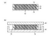
本実施形態によるカーボンナノチューブシート10は、図41(a)に示すように、シートの膜厚方向、すなわちシートの表面と交差する方向に配向した複数のカーボンナノチューブ16を有している。カーボンナノチューブ16の間隙には、充填層38が形成されている。充填層38は、シートの内部に設けられた支持層38aと、支持層38aを挟むようにシートの両表面側に形成された低融点材料層38b,38cとを有している。 As shown in FIG. 41A, the
カーボンナノチューブシート10は、例えば図41(b)に示すように、被着体40と被着体42との間に設けられ、被着体40と被着体42との間の熱伝導性や電気伝導性を向上するためのものである。被着体40,42は、例えば、発熱体や放熱体である。被着体40と被着体42との間に設けられる際、カーボンナノチューブシート10の低融点材料層38b,38cは、被着体40,42の表面凹凸に応じて形状変化し、カーボンナノチューブシート10と被着体40,42との間の密着性を向上する。 For example, as shown in FIG. 41B, the
カーボンナノチューブ16は、単層カーボンナノチューブ及び多層カーボンナノチューブのいずれでもよい。カーボンナノチューブ16の面密度は、特に限定されるものではないが、放熱性及び電気伝導性の観点からは、1×10¹⁰本/cm2以上の平面密度であることが望ましい。後述の製造方法を用いることにより、成長時の面密度を超えた高い面密度でカーボンナノチューブ16を形成することができる。The
カーボンナノチューブ12の長さ(シートの厚さ)は、カーボンナノチューブシート10の用途によって決まり、特に限定されるものではないが、好ましくは5μm〜500μm程度の値に設定することができる。 The length (sheet thickness) of the
支持層38aは、カーボンナノチューブシート10を使用する際にカーボンナノチューブ16が移動(例えば、傾斜したり凝集したりするなど)して配向性を失わないように支持するためのものである。この目的のもと、支持層38aは、少なくともカーボンナノチューブシート10が曝される温度において固体である材料により形成する。カーボンナノチューブシート10が曝される熱としては、カーボンナノチューブシート10を被着体40,42に熱圧着(リフロー)する際の加熱、半導体素子の駆動時の発熱、等が挙げられる。 The
支持層38aの材料は、形成する際に液状であり硬化することができ、少なくともカーボンナノチューブシート10が曝される温度において固体であれば、特に限定されるものではない。支持層38aの材料としては、例えば熱硬化性樹脂や熱可塑性樹脂を適用することができる。 The material of the
低融点材料層38b,38cは、カーボンナノチューブシート10を被着体に接したときに、カーボンナノチューブシート10と被着体40,42との間の隙間を充填するためのものである。この目的のもと、低融点材料層38b,38cは、熱圧着或いは圧着によって被着体40,42の表面形状に応じて形状変化しうる材料により形成する。低融点材料層38b,38cは、いずれか一方のみを設けるようにしてもよい。 The low melting point material layers 38b and 38c are for filling a gap between the
熱圧着によって被着体40,42の表面形状に応じて形状変化しうる材料としては、常温において固体であり、加熱により軟化して液状或いはゲル状となる物質を適用することができる。ただし、低融点材料層38b,38cの材料の融点が支持層38aの材料の融点以上では、低融点材料層38b,38cを熱圧着する際に支持層38aまでもが軟化してカーボンナノチューブ16を支持できなくなる。このため、低融点材料層38b,38cの材料の融点は、支持層38aの融点未満であることが望ましい。 As a material whose shape can be changed according to the surface shape of the adherends 40 and 42 by thermocompression bonding, a material that is solid at normal temperature and softens by heating to become liquid or gel can be applied. However, when the melting point of the material of the low melting point material layers 38b and 38c is equal to or higher than the melting point of the material of the
低融点材料層38b,38cは、カーボンナノチューブシート10と被着体40,42との間の密着性、すなわち接触熱抵抗をより低減する観点からは、カーボンナノチューブシート10が搭載される装置の駆動時の上限温度において固体の材料であることが望ましい。 The low-melting-point material layers 38b and 38c drive the device on which the
すなわち、低融点材料層38b,38cとしては、融点が、カーボンナノチューブシート10が搭載される装置の駆動時の上限温度(例えば、発熱体の発熱温度)よりも高く、支持層38aの材料の融点よりも低い材料が望ましい。特に、温度に応じて液体と固体との間で可逆的に状態変化するものであり、常温では固体であり、加熱すると液状に変化し、冷却すると接着性を発現しつつ固体に戻る熱可塑性樹脂が好適である。 That is, as the low melting point material layers 38b and 38c, the melting point is higher than the upper limit temperature at the time of driving the device on which the
低融点材料層38b,38cの融点の上限値は、支持層38aの融点未満であることに加え、被着体40,42の耐熱温度の下限値よりも低いことが望ましい。低融点材料層38b,38cの融点が被着体40,42の耐熱温度より高いと、被着体40,42にダメージを与えることなく熱圧着することが困難となるからである。 The upper limit value of the melting point of the low melting point material layers 38b and 38c is preferably lower than the lower limit value of the heat resistant temperature of the adherends 40 and 42 in addition to being lower than the melting point of the
次に、本実施形態によるカーボンナノチューブシートの製造方法について図42乃至図47を用いて説明する。 Next, the method for manufacturing the carbon nanotube sheet according to the present embodiment will be explained with reference to FIGS.
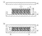
まず、図3に示す第1実施形態によるカーボンナノチューブシートの製造方法と同様にして、基板12上に、カーボンナノチューブ16を成長する。 First, the
次いで、カーボンナノチューブ16上に、膜厚6μm程度のフォトレジスト膜36を塗布した熱収縮性シート20を、フォトレジスト膜36の塗布面がカーボンナノチューブ16側に位置するように載置する。 Next, the heat-
次いで、例えば90℃の熱処理によりフォトレジスト膜36を硬化させる(図42(a))。これにより、カーボンナノチューブ16の端部はフォトレジスト膜36によって覆われ、カーボンナノチューブ16はフォトレジスト膜36によって熱収縮性シート20上に接着される。 Next, the
次いで、熱収縮性シート20を、カーボンナノチューブ16とともに基板12から剥離する。こうして、カーボンナノチューブ16を、熱収縮性シート20上に転写する(図42(b))。 Next, the heat-
フォトレジスト膜36は、基板12上に形成したカーボンナノチューブ16を熱収縮性シート20側に転写するために用いるものであるとともに、支持層38aを形成する際にカーボンナノチューブ16の端部が支持層38aで覆われるのを防止するためのレジスト膜である。フォトレジスト膜36の代わりに、第1乃至第8実施形態で使用した接着剤22を用いてもよい。 The
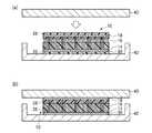
次いで、余分なフォトレジスト膜36を除去した後、上下から均等に熱が加わる加熱装置を用い、熱収縮性シート20の熱収縮温度よりも高い温度、例えば140℃で加熱して、熱収縮性シート20を収縮させる。 Next, after removing the
この熱処理により、熱収縮性シート20は収縮し、カーボンナノチューブ16が形成された領域も、熱収縮性シート20と同様に収縮する。結果として、カーボンナノチューブ16が形成された面積は元の面積に比べて約1/4程度となり、面密度は約4倍となる(図43参照)。フォトレジスト膜36の膜厚が6μm程度であれば、熱収縮性シート20の熱収縮がフォトレジスト膜36によって阻害されることはない。 By this heat treatment, the heat-
次いで、例えばスピンコート法により、支持層38aとなる充填材を塗布する。この際、カーボンナノチューブ16の端部上の充填材の厚さが数百nm以下になるように、塗布溶液の粘度やスピンコータの回転数を適宜設定する。 Next, a filler to be the
支持層38aとなる充填材は、その後に硬化できるものであり、後にカーボンナノチューブシート10が曝される温度において固体であれば、特に限定されるものではない。ここでは、支持層38aとなる充填材として、シリコーン系樹脂を用いるものとする。 The filler used as the
支持層38aとなる充填材は、例えば、有機系充填材としては、アクリル樹脂、エポキシ樹脂、シリコーン樹脂、ポリイミド樹脂などを適用することができる。また、無機系充填材としては、SOG(Spin On Glass)などの塗布型絶縁膜形成用組成物などを適用することができる。また、インジウム、はんだ、金属ペースト(例えば、銀ペースト)などの金属材料を適用することもできる。また、例えばポリアニリン、ポリチオフェンなどの導電性ポリマを適用することもできる。 As the filler used as the
次いで、充填材を硬化して、支持層38aを形成する(図44)。充填材の硬化方法は、特に限定されるものではなく、常温において長時間放置してもよいし、熱処理や紫外線照射等を用いてもよい。熱処理を行う場合、熱を加えすぎるとフォトレジスト膜36が過度に硬化してしまい、後に熱収縮性シート20からカーボンナノチューブ16を剥離しにくくなる。かかる観点から、支持層38aとなる充填材としては、フォトレジスト材料が硬化する温度(例えば90℃程度)よりも低い温度で硬化できる材料を適用することが好ましい。 Next, the filler is cured to form the
次いで、例えば有機溶剤によりフォトレジスト膜36を選択的に除去し、支持層38aに埋め込まれたカーボンナノチューブ16を、熱収縮性シート20から剥離する(図45)。この際、シリコーン系樹脂は有機溶剤に対して耐エッチング性を有しているため、フォトレジスト膜36の除去の際にシリコーン系樹脂の支持層38aがダメージを受けることはない。 Next, the
フォトレジスト膜36を除去することにより、フォトレジスト膜36により覆われていたカーボンナノチューブ16の一端部は、支持層38aによって覆われずに露出することになる。 By removing the
次いで、熱収縮性シート20から剥離したシートの両面に、フィルム状に加工した低融点材料層38b,38c形成用の熱可塑性樹脂を、支持層38aの形成材料の融点未満の温度で熱圧着し、熱可塑性樹脂の低融点材料層38b,38cを形成する。これにより、カーボンナノチューブ16の両端が低融点材料層38b,38cによって埋め込まれ、支持層38a及び低融点材料層38b,38cを有する充填層38が形成される。 Next, the thermoplastic resin for forming the low-melting-point material layers 38b and 38c processed into a film shape is thermocompression bonded to both surfaces of the sheet peeled from the heat-
低融点材料層38b,38cとして常温でも液状体やゲル状体の材料、例えば低粘度の放熱用グリース等を用いる場合、例えばスピンコート法により、低融点材料層38b,38cを形成することができる。 When a low-melting
低融点材料層38b,38cに好適な熱可塑性樹脂としては、例えば、上述の熱可塑性樹脂フィルム24に適用可能なホットメルト樹脂と同様のホットメルト樹脂を適用することができる。 As a thermoplastic resin suitable for the low melting point material layers 38b and 38c, for example, a hot melt resin similar to the hot melt resin applicable to the above-described
これらホットメルト樹脂の中から、融点が高いものを支持層38aの材料として、融点が低いものを低融点材料層38b,38cの材料として、選択してもよい。例えば、支持層38aの材料としてヘンケルジャパン株式会社製の「Micromelt6239」を用い、低融点材料層38b,38cの材料として日本マタイ株式会社製の「エルファンNT−120」を用いることができる。 Of these hot melt resins, one having a high melting point may be selected as the material for the
圧着によって被着体の表面形状に応じて形状変化しうる材料としては、常温において液状或いはゲル状の物質を適用することができる。低融点材料層14b,14cに適用可能な液状体やゲル状体の材料としては、例えば、低粘度の放熱用グリース等が挙げられる。 As a material whose shape can be changed depending on the surface shape of the adherend by pressure bonding, a liquid or gel substance can be applied at room temperature. Examples of the liquid or gel material that can be applied to the low-melting-point material layers 14b and 14c include low-viscosity grease for heat dissipation.
こうして、本実施形態によるカーボンナノチューブシート10を得る(図46)。 Thus, the
次いで、上述のようにして形成したカーボンナノチューブシート10を、LSIチップ40とヒートスプレッダ42との間に設置し、低融点材料層38b,38cの軟化温度よりも高い温度で加熱圧着する(図37(a)参照)。これにより、圧着時に低融点材料層38b,38cが液化し、端部のカーボンナノチューブ16のバネ性が得られる構造となる。 Next, the
次いで、室温まで冷却し、低融点材料層38b,38cを固化する(図40)。これにより、室温に冷却した後も、カーボンナノチューブシート10とLSIチップ42及びヒートスプレッダ44との間の低い接触熱抵抗を維持することができる。 Subsequently, it cools to room temperature and solidifies the low melting-point material layers 38b and 38c (FIG. 40). Thereby, even after cooling to room temperature, a low contact thermal resistance between the
このように、本実施形態によれば、熱収縮性を有する基板上にカーボンナノチューブを形成し、基板を熱収縮した後に充填層を形成してシート化するので、成長時の面密度を超えた高い面密度で形成されたカーボンナノチューブを有するカーボンナノチューブシートを製造することができる。これにより、カーボンナノチューブシートの熱伝導性及び導電性を大幅に向上することができる。 As described above, according to the present embodiment, the carbon nanotubes are formed on the heat-shrinkable substrate, the filling layer is formed after the substrate is heat-shrinked, and the sheet is formed, so that the surface density at the time of growth was exceeded. A carbon nanotube sheet having carbon nanotubes formed with a high surface density can be manufactured. Thereby, the thermal conductivity and conductivity of the carbon nanotube sheet can be greatly improved.
また、低融点材料層によってシートのリフロー性を確保することができるとともに、リフローによるカーボンナノチューブの配向性のみだれを支持層によって防止することができる。これにより、被着体に対する接触熱抵抗及び接触抵抗の小さいカーボンナノチューブシートを容易に形成することができる。また、カーボンナノチューブの端部を支持層の表面よりも突出させることにより、カーボンナノチューブのバネ性を発現することができ、被着体に対する接触熱抵抗及び接触抵抗を低減することができる。 Further, the reflowability of the sheet can be ensured by the low melting point material layer, and the orientation of the carbon nanotube due to the reflow can be prevented by the support layer. Thereby, a carbon nanotube sheet with low contact thermal resistance and contact resistance to the adherend can be easily formed. Further, by projecting the end portion of the carbon nanotube from the surface of the support layer, the spring property of the carbon nanotube can be expressed, and the contact thermal resistance and contact resistance to the adherend can be reduced.
[第10実施形態]
第10実施形態によるカーボンナノチューブシート及びその製造方法について図48を用いて説明する。なお、図1乃至図47に示す第1乃至第9実施形態によるカーボンナノチューブシート及びその製造方法と同様の構成要素には同一の符号を付し説明を省略し又は簡潔にする。[Tenth embodiment]
The carbon nanotube sheet and the manufacturing method thereof according to the tenth embodiment will be described with reference to FIG. Components similar to those of the carbon nanotube sheet and the manufacturing method thereof according to the first to ninth embodiments shown in FIGS. 1 to 47 are denoted by the same reference numerals, and description thereof is omitted or simplified.
図48は、本実施形態によるカーボンナノチューブシートの構造を示す概略断面図である。 FIG. 48 is a schematic cross-sectional view showing the structure of the carbon nanotube sheet according to the present embodiment.
はじめに、本実施形態によるカーボンナノチューブシートの構造について図48を用いて説明する。 First, the structure of the carbon nanotube sheet according to the present embodiment will be explained with reference to FIG.
本実施形態によるカーボンナノチューブシートは、図48に示すように、カーボンナノチューブ16の低融点材料層38c側の端部に、被膜18が形成されているほかは、図41に示す第9実施形態によるカーボンナノチューブシートと同様である。 As shown in FIG. 48, the carbon nanotube sheet according to the present embodiment is the same as that of the ninth embodiment shown in FIG. 41 except that the
被膜18を形成する材料は、充填層38の構成材料よりも熱伝導率の高い材料であれば、特に限定されるものではない。 The material for forming the
熱伝導性の高い被膜18を設けることにより、被膜18を設けない場合と比較して、カーボンナノチューブシート10の被着体(例えば、放熱体や発熱体)に対する接触面積を増加することができる。これにより、カーボンナノチューブ16と被着体との間の接触熱抵抗が低減され、カーボンナノチューブシート10の熱伝導性を高めることができる。カーボンナノチューブシート10を導電性シートとしても用いる場合には、導電性を高めることができる。 By providing the
次に、本実施形態によるカーボンナノチューブシートの製造方法について説明する。なお、本実施形態は、第9実施形態によるカーボンナノチューブシートにおいて、第2実施形態によるカーボンナノチューブシートと同様の手法により被膜18を形成するものである。ここでは、新たな図面を使用せず、これら実施形態の図面を参照して説明するものとする。 Next, the method for manufacturing the carbon nanotube sheet according to the present embodiment will be described. In the present embodiment, in the carbon nanotube sheet according to the ninth embodiment, the
まず、図3に示す第1実施形態によるカーボンナノチューブシートの製造方法と同様にして、基板12上に、カーボンナノチューブ16を成長する。 First, the
次いで、カーボンナノチューブ16上に、例えば蒸着法により、例えば膜厚数百nmのAuを形成し、Auの被膜18を形成する(図11(a)参照)。 Next, Au having a film thickness of, for example, several hundreds of nanometers is formed on the
被膜18を形成する材料は、充填層38の構成材料よりも熱伝導率の高い材料であれば特に限定されるものではない。 The material for forming the
被膜18の膜厚は、後工程においてフォトレジスト膜36の浸透を阻害しない膜厚であれば、特に限定されるものではない。被膜30の膜厚は、フォトレジスト膜36の浸透性、カーボンナノチューブシート10に要求される特性、被膜18の構成材料等に応じて適宜設定することが望ましい。 The film thickness of the
次いで、被膜18を形成したカーボンナノチューブ16上に、フォトレジスト膜36を塗布した熱収縮性シート20を、フォトレジスト膜36の塗布面がカーボンナノチューブ16側に位置するように載置する。 Next, the heat-
次いで、例えば90℃の熱処理によりフォトレジスト膜36を硬化させる(図42(a)参照)。これにより、カーボンナノチューブ16の端部はフォトレジスト膜36によって覆われ、カーボンナノチューブ16はフォトレジスト膜36によって熱収縮性シート20上に接着される。 Next, the
次いで、熱収縮性シート20を、カーボンナノチューブ16とともに基板12から剥離する。こうして、カーボンナノチューブ16を、熱収縮性シート20上に転写する(図42(b)参照)。 Next, the heat-
次いで、余分なフォトレジスト膜36を除去した後、上下から均等に熱が加わる加熱装置を用いて熱収縮性シート20を収縮させる。この熱処理により、熱収縮性シート20は収縮し、カーボンナノチューブ16が形成された領域も、熱収縮性シート20と同様に収縮する。結果として、カーボンナノチューブ16が形成された面積は元の面積に比べて約1/4程度となり、面密度は約4倍となる(図43参照)。 Next, after removing the
次いで、例えばスピンコート法により、支持層38aとなる充填材を塗布する。この際、カーボンナノチューブ16の端部上の充填材の厚さが数百nm以下になるように、塗布溶液の粘度やスピンコータの回転数を適宜設定する。 Next, a filler to be the
次いで、充填材を硬化して、支持層38aを形成する(図44参照)。 Next, the filler is cured to form the
次いで、例えば有機溶剤によりフォトレジスト膜36を選択的に除去し、支持層38aに埋め込まれたカーボンナノチューブ16を、熱収縮性シート20から剥離する(図45参照)。フォトレジスト膜36を除去することにより、フォトレジスト膜36により覆われていたカーボンナノチューブ16の一端部は、支持層38aによって覆われずに露出することになる。 Next, the
次いで、熱収縮性シート20から剥離したシートの両面に、フィルム状に加工した低融点材料層38b,38c形成用の熱可塑性樹脂を、支持層38aの形成材料の融点未満の温度で熱圧着し、熱可塑性樹脂の低融点材料層38b,38cを形成する。これにより、カーボンナノチューブ16の両端が低融点材料層38b,38cによって埋め込まれ、支持層38a及び低融点材料層38b,38cを有する充填層38が形成される。 Next, the thermoplastic resin for forming the low-melting-point material layers 38b and 38c processed into a film shape is thermocompression bonded to both surfaces of the sheet peeled from the heat-
こうして、本実施形態によるカーボンナノチューブシート10を得る(図46)。 Thus, the
次いで、上述のようにして形成したカーボンナノチューブシート10を、LSIチップ40とヒートスプレッダ42との間に設置し、低融点材料層38b,38cの軟化温度よりも高い温度で加熱圧着する(図37(a)参照)。これにより、圧着時に低融点材料層38b,38cが液化し、端部のカーボンナノチューブ16のバネ性が得られる構造となる。 Next, the
次いで、室温まで冷却し、低融点材料層38b,38cを固化する(図40)。これにより、室温に冷却した後も、カーボンナノチューブシート10とLSIチップ42及びヒートスプレッダ44との間の低い接触熱抵抗を維持することができる。 Subsequently, it cools to room temperature and solidifies the low melting-point material layers 38b and 38c (FIG. 40). Thereby, even after cooling to room temperature, a low contact thermal resistance between the
このように、本実施形態によれば、カーボンナノチューブの端部に熱伝導性の高い被膜を形成するので、被着体に対する接触熱抵抗及び接触抵抗を低減することができる。これにより、カーボンナノチューブシートの熱伝導性及び導電性を更に向上することができる。 Thus, according to this embodiment, since the coating film having high thermal conductivity is formed at the end of the carbon nanotube, the contact thermal resistance and the contact resistance with respect to the adherend can be reduced. Thereby, the thermal conductivity and conductivity of the carbon nanotube sheet can be further improved.
[第11実施形態]
第11実施形態によるカーボンナノチューブシート及びその製造方法について図49を用いて説明する。なお、図1乃至図48に示す第1乃至第10実施形態によるカーボンナノチューブシート及びその製造方法と同様の構成要素には同一の符号を付し説明を省略し又は簡潔にする。[Eleventh embodiment]
The carbon nanotube sheet and the manufacturing method thereof according to the eleventh embodiment will be described with reference to FIG. Components similar to those of the carbon nanotube sheet and the manufacturing method thereof according to the first to tenth embodiments shown in FIGS. 1 to 48 are denoted by the same reference numerals, and description thereof is omitted or simplified.
図49は、本実施形態によるカーボンナノチューブシートの構造を示す概略断面図である。 FIG. 49 is a schematic sectional view showing the structure of the carbon nanotube sheet according to the present embodiment.
はじめに、本実施形態によるカーボンナノチューブシートの構造について図49を用いて説明する。 First, the structure of the carbon nanotube sheet according to the present embodiment will be explained with reference to FIG.
本実施形態によるカーボンナノチューブシートは、図48に示すように、カーボンナノチューブ16の低融点材料層38b側の端部に、被膜30が形成されているほかは、図41に示す第9実施形態によるカーボンナノチューブシートと同様である。 As shown in FIG. 48, the carbon nanotube sheet according to the present embodiment is the same as that of the ninth embodiment shown in FIG. 41 except that the
被膜30を形成する材料は、充填層38の構成材料よりも熱伝導率の高い材料であれば、特に限定されるものではない。 The material for forming the
熱伝導性の高い被膜30を設けることにより、被膜30を設けない場合と比較して、カーボンナノチューブシート10の被着体(例えば、放熱体や発熱体)に対する接触面積を増加することができる。これにより、カーボンナノチューブ16と被着体との間の接触熱抵抗が低減され、カーボンナノチューブシート10の熱伝導性を高めることができる。カーボンナノチューブシート10を導電性シートとしても用いる場合には、導電性を高めることができる。 By providing the
次に、本実施形態によるカーボンナノチューブシートの製造方法について説明する。なお、本実施形態は、第9実施形態によるカーボンナノチューブシートにおいて、第3実施形態によるカーボンナノチューブシートと同様の手法により被膜30を形成するものである。ここでは、新たな図面を使用せず、これら実施形態の図面を参照して説明するものとする。 Next, the method for manufacturing the carbon nanotube sheet according to the present embodiment will be described. In the present embodiment, in the carbon nanotube sheet according to the ninth embodiment, the
まず、図3に示す第1実施形態によるカーボンナノチューブシートの製造方法と同様にして、基板12上に、カーボンナノチューブ16を成長する。 First, the
次いで、カーボンナノチューブ16上に、フォトレジスト膜36を塗布した熱収縮性シート20を、フォトレジスト膜36の塗布面がカーボンナノチューブ16側に位置するように載置する。 Next, the heat-
次いで、例えば90℃の熱処理によりフォトレジスト膜36を硬化させる(図42(a)参照)。これにより、カーボンナノチューブ16の端部はフォトレジスト膜36によって覆われ、カーボンナノチューブ16はフォトレジスト膜36によって熱収縮性シート20上に接着される。 Next, the
次いで、熱収縮性シート20を、カーボンナノチューブ16とともに基板12から剥離する。こうして、カーボンナノチューブ16を、熱収縮性シート20上に転写する(図42(b)参照)。 Next, the heat-
次いで、余分なフォトレジスト膜36を除去した後、上下から均等に熱が加わる加熱装置を用いて熱収縮性シート20を収縮させる。この熱処理により、熱収縮性シート20は収縮し、カーボンナノチューブ16が形成された領域も、熱収縮性シート20と同様に収縮する。結果として、カーボンナノチューブ16が形成された面積は元の面積に比べて約1/4程度となり、面密度は約4倍となる(図43参照)。 Next, after removing the
次いで、カーボンナノチューブ16上に、例えば蒸着法により、例えば膜厚数百nmのAuを形成し、Auの被膜30を形成する(図19参照)。 Next, Au having a film thickness of, for example, several hundred nm is formed on the
被膜30を形成する材料は、充填層38の構成材料よりも熱伝導率の高い材料であれば特に限定されるものではない。 The material for forming the
次いで、例えばスピンコート法により、支持層38aとなる充填材を塗布する。この際、カーボンナノチューブ16の端部上の充填材の厚さが数百nm以下になるように、塗布溶液の粘度やスピンコータの回転数を適宜設定する。 Next, a filler to be the
次いで、充填材を硬化して、支持層38aを形成する(図44参照)。 Next, the filler is cured to form the
次いで、例えば有機溶剤によりフォトレジスト膜36を選択的に除去し、支持層38aに埋め込まれたカーボンナノチューブ16を、熱収縮性シート20から剥離する(図45参照)。フォトレジスト膜36を除去することにより、フォトレジスト膜36により覆われていたカーボンナノチューブ16の一端部は、支持層38aによって覆われずに露出することになる。 Next, the
次いで、熱収縮性シート20から剥離したシートの両面に、フィルム状に加工した低融点材料層38b,38c形成用の熱可塑性樹脂を、支持層38aの形成材料の融点未満の温度で熱圧着し、熱可塑性樹脂の低融点材料層38b,38cを形成する。これにより、カーボンナノチューブ16の両端が低融点材料層38b,38cによって埋め込まれ、支持層38a及び低融点材料層38b,38cを有する充填層38が形成される。 Next, the thermoplastic resin for forming the low-melting-point material layers 38b and 38c processed into a film shape is thermocompression bonded to both surfaces of the sheet peeled from the heat-
こうして、本実施形態によるカーボンナノチューブシート10を得る(図46)。 Thus, the
次いで、上述のようにして形成したカーボンナノチューブシート10を、LSIチップ40とヒートスプレッダ42との間に設置し、低融点材料層38b,38cの軟化温度よりも高い温度で加熱圧着する(図37(a)参照)。これにより、圧着時に低融点材料層38b,38cが液化し、端部のカーボンナノチューブ16のバネ性が得られる構造となる。 Next, the
次いで、室温まで冷却し、低融点材料層38b,38cを固化する(図40)。これにより、室温に冷却した後も、カーボンナノチューブシート10とLSIチップ42及びヒートスプレッダ44との間の低い接触熱抵抗を維持することができる。 Subsequently, it cools to room temperature and solidifies the low melting-point material layers 38b and 38c (FIG. 40). Thereby, even after cooling to room temperature, a low contact thermal resistance between the
このように、本実施形態によれば、カーボンナノチューブの端部に熱伝導性の高い被膜を形成するので、被着体に対する接触熱抵抗及び接触抵抗を低減することができる。これにより、カーボンナノチューブシートの熱伝導性及び導電性を更に向上することができる。 Thus, according to this embodiment, since the coating film having high thermal conductivity is formed at the end of the carbon nanotube, the contact thermal resistance and the contact resistance with respect to the adherend can be reduced. Thereby, the thermal conductivity and conductivity of the carbon nanotube sheet can be further improved.
[第12実施形態]
第12実施形態によるカーボンナノチューブシート及びその製造方法について図50を用いて説明する。なお、図1乃至図49に示す第1乃至第11実施形態によるカーボンナノチューブシート及びその製造方法と同様の構成要素には同一の符号を付し説明を省略し又は簡潔にする。[Twelfth embodiment]
The carbon nanotube sheet and the manufacturing method thereof according to the twelfth embodiment will be described with reference to FIG. Components similar to those of the carbon nanotube sheet and the manufacturing method thereof according to the first to eleventh embodiments shown in FIGS. 1 to 49 are denoted by the same reference numerals, and description thereof is omitted or simplified.
図50は、本実施形態によるカーボンナノチューブシートの構造を示す概略断面図である。 FIG. 50 is a schematic cross-sectional view showing the structure of the carbon nanotube sheet according to the present embodiment.
はじめに、本実施形態によるカーボンナノチューブシートの構造について図50を用いて説明する。 First, the structure of the carbon nanotube sheet according to the present embodiment will be explained with reference to FIG.
本実施形態によるカーボンナノチューブシートは、図50に示すように、カーボンナノチューブ16の両端部に、被膜18,30が形成されているほかは、図41に示す第9実施形態によるカーボンナノチューブシートと同様である。 The carbon nanotube sheet according to the present embodiment is the same as the carbon nanotube sheet according to the ninth embodiment shown in FIG. 41 except that the
熱伝導性の高い被膜18,30を設けることにより、被膜18,30を設けない場合と比較して、カーボンナノチューブシート10の被着体(例えば、放熱体や発熱体)に対する接触面積を増加することができる。これにより、カーボンナノチューブ16と被着体との間の接触熱抵抗が低減され、カーボンナノチューブシート10の熱伝導性を高めることができる。カーボンナノチューブシート10を導電性シートとしても用いる場合には、導電性を高めることができる。被膜18,30の一方を設ける場合と比較して、カーボンナノチューブ16と被着体との間の熱電導性及び導電性を更に高めることができる。 By providing the
次に、本実施形態によるカーボンナノチューブシートの製造方法について説明する。なお、本実施形態は、第9実施形態によるカーボンナノチューブシートにおいて、第2実施形態によるカーボンナノチューブシートと同様の手法により被膜30を形成するものである。ここでは、新たな図面を使用せず、これら実施形態の図面を参照して説明するものとする。 Next, the method for manufacturing the carbon nanotube sheet according to the present embodiment will be described. In the present embodiment, in the carbon nanotube sheet according to the ninth embodiment, the
まず、図3に示す第1実施形態によるカーボンナノチューブシートの製造方法と同様にして、基板12上に、カーボンナノチューブ16を成長する。 First, the
次いで、カーボンナノチューブ16上に、例えば蒸着法により、例えば膜厚数百nmのAuを形成し、Auの被膜18を形成する(図11(a)参照)。 Next, Au having a film thickness of, for example, several hundreds of nanometers is formed on the
被膜18を形成する材料は、充填層38の構成材料よりも熱伝導率の高い材料であれば特に限定されるものではない。 The material for forming the
被膜18の膜厚は、後工程においてフォトレジスト膜36の浸透を阻害しない膜厚であれば、特に限定されるものではない。被膜30の膜厚は、フォトレジスト膜36の浸透性、カーボンナノチューブシート10に要求される特性、被膜18の構成材料等に応じて適宜設定することが望ましい。 The film thickness of the
次いで、被膜18を形成したカーボンナノチューブ16上に、フォトレジスト膜36を塗布した熱収縮性シート20を、フォトレジスト膜36の塗布面がカーボンナノチューブ16側に位置するように載置する。 Next, the heat-
次いで、例えば90℃の熱処理によりフォトレジスト膜36を硬化させる(図42(a)参照)。これにより、カーボンナノチューブ16の端部はフォトレジスト膜36によって覆われ、カーボンナノチューブ16はフォトレジスト膜36によって熱収縮性シート20上に接着される。 Next, the
次いで、熱収縮性シート20を、カーボンナノチューブ16とともに基板12から剥離する。こうして、カーボンナノチューブ16を、熱収縮性シート20上に転写する(図42(b)参照)。 Next, the heat-
次いで、余分なフォトレジスト膜36を除去した後、上下から均等に熱が加わる加熱装置を用いて熱収縮性シート20を収縮させる。この熱処理により、熱収縮性シート20は収縮し、カーボンナノチューブ16が形成された領域も、熱収縮性シート20と同様に収縮する。結果として、カーボンナノチューブ16が形成された面積は元の面積に比べて約1/4程度となり、面密度は約4倍となる(図43参照)。 Next, after removing the
次いで、カーボンナノチューブ16上に、例えば蒸着法により、例えば膜厚数百nmのAuを形成し、Auの被膜30を形成する(図19参照)。 Next, Au having a film thickness of, for example, several hundred nm is formed on the
被膜30を形成する材料は、充填層38の構成材料よりも熱伝導率の高い材料であれば特に限定されるものではない。 The material for forming the
次いで、例えばスピンコート法により、支持層38aとなる充填材を塗布する。この際、カーボンナノチューブ16の端部上の充填材の厚さが数百nm以下になるように、塗布溶液の粘度やスピンコータの回転数を適宜設定する。 Next, a filler to be the
次いで、充填材を硬化して、支持層38aを形成する(図44参照)。 Next, the filler is cured to form the
次いで、例えば有機溶剤によりフォトレジスト膜36を選択的に除去し、支持層38aに埋め込まれたカーボンナノチューブ16を、熱収縮性シート20から剥離する(図45参照)。フォトレジスト膜36を除去することにより、フォトレジスト膜36により覆われていたカーボンナノチューブ16の一端部は、支持層38aによって覆われずに露出することになる。 Next, the
次いで、熱収縮性シート20から剥離したシートの両面に、フィルム状に加工した低融点材料層38b,38c形成用の熱可塑性樹脂を、支持層38aの形成材料の融点未満の温度で熱圧着し、熱可塑性樹脂の低融点材料層38b,38cを形成する。これにより、カーボンナノチューブ16の両端が低融点材料層38b,38cによって埋め込まれ、支持層38a及び低融点材料層38b,38cを有する充填層38が形成される。 Next, the thermoplastic resin for forming the low-melting-point material layers 38b and 38c processed into a film shape is thermocompression bonded to both surfaces of the sheet peeled from the heat-
こうして、本実施形態によるカーボンナノチューブシート10を得る(図46)。 Thus, the
次いで、上述のようにして形成したカーボンナノチューブシート10を、LSIチップ40とヒートスプレッダ42との間に設置し、低融点材料層38b,38cの軟化温度よりも高い温度で加熱圧着する(図37(a)参照)。これにより、圧着時に低融点材料層38b,38cが液化し、端部のカーボンナノチューブ16のバネ性が得られる構造となる。 Next, the
次いで、室温まで冷却し、低融点材料層38b,38cを固化する(図40)。これにより、室温に冷却した後も、カーボンナノチューブシート10とLSIチップ42及びヒートスプレッダ44との間の低い接触熱抵抗を維持することができる。 Subsequently, it cools to room temperature and solidifies the low melting-point material layers 38b and 38c (FIG. 40). Thereby, even after cooling to room temperature, a low contact thermal resistance between the
このように、本実施形態によれば、カーボンナノチューブの端部に熱伝導性の高い被膜を形成するので、被着体に対する接触熱抵抗及び接触抵抗を低減することができる。これにより、カーボンナノチューブシートの熱伝導性及び導電性を更に向上することができる。 Thus, according to this embodiment, since the coating film having high thermal conductivity is formed at the end of the carbon nanotube, the contact thermal resistance and the contact resistance with respect to the adherend can be reduced. Thereby, the thermal conductivity and conductivity of the carbon nanotube sheet can be further improved.
[第13実施形態]
第13実施形態によるカーボンナノチューブシート及びその製造方法について図51乃至図60を用いて説明する。なお、図1乃至図50に示す第1乃至第12実施形態によるカーボンナノチューブシート及びその製造方法と同様の構成要素には同一の符号を付し説明を省略し又は簡潔にする。[Thirteenth embodiment]
The carbon nanotube sheet and the manufacturing method thereof according to the thirteenth embodiment will be described with reference to FIGS. Components similar to those in the carbon nanotube sheet and the manufacturing method thereof according to the first to twelfth embodiments shown in FIGS. 1 to 50 are denoted by the same reference numerals, and description thereof is omitted or simplified.
図51は、本実施形態によるカーボンナノチューブシートの構造を示す概略断面図である。図52乃至図60は、本実施形態によるカーボンナノチューブシートの製造方法を示す工程断面図である。 FIG. 51 is a schematic cross-sectional view showing the structure of the carbon nanotube sheet according to the present embodiment. 52 to 60 are process cross-sectional views illustrating the method of manufacturing the carbon nanotube sheet according to the present embodiment.
はじめに、本実施形態によるカーボンナノチューブシートの構造について図51を用いて説明する。 First, the structure of the carbon nanotube sheet according to the present embodiment will be explained with reference to FIG.
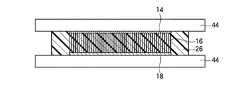
本実施形態によるカーボンナノチューブシートは、図51に示すように、カーボンナノチューブ16が、1層の充填層26によって支持されているほかは、図2に示す第1実施形態によるカーボンナノチューブシートと同様である。 The carbon nanotube sheet according to the present embodiment is the same as the carbon nanotube sheet according to the first embodiment shown in FIG. 2 except that the
次に、本実施形態によるカーボンナノチューブシートの製造方法について図52乃至図60を用いて説明する。 Next, the method for manufacturing the carbon nanotube sheet according to the present embodiment will be explained with reference to FIGS.
まず、図3に示す第1実施形態によるカーボンナノチューブシートの製造方法と同様にして、基板12上に、カーボンナノチューブ16を成長する(図52)。 First, the
次いで、カーボンナノチューブ16上に、例えば蒸着法により、例えば膜厚数百nmのAuを形成し、Auの被膜18を形成する(図53)。 Next, Au having a film thickness of, for example, several hundred nm is formed on the
次いで、被膜18を形成したカーボンナノチューブ16上に、熱可塑性樹脂フィルム24を載置する。なお、熱可塑性樹脂フィルム24を形成する熱可塑性樹脂材料としては、融点が、後述する熱収縮性シート20の収縮温度よりも低いものを適用する。 Next, the
次いで、熱可塑性樹脂フィルム24を形成する熱可塑性樹脂材料の軟化温度よりも高い温度で加熱し、溶解した熱可塑性樹脂材料をカーボンナノチューブ16の間隙に浸透させ、充填層26を形成する(図54)。なお、熱可塑性樹脂材料は、基板12の表面には達しない程度まで浸透させることが望ましい。これは、後工程においてカーボンナノチューブ16を基板12から剥離するのを容易にするためである。 Next, heating is performed at a temperature higher than the softening temperature of the thermoplastic resin material forming the
次いで、図4(a)に示す第1実施形態によるカーボンナノチューブシートの製造方法と同様にして、充填層26上に、接着剤22によって熱収縮性シート20を接着する。 Next, the heat-
次いで、図4(b)に示す第1実施形態によるカーボンナノチューブシートの製造方法と同様にして、カーボンナノチューブ16を、充填層26とともに基板12から剥離する(図55)。 Next, the
次いで、上下から均等に熱が加わる加熱装置を用いて熱収縮性シート20を収縮させる(図56)。この熱処理により、熱収縮性シート20は収縮し、カーボンナノチューブ16が形成された領域も、熱収縮性シート20と同様に収縮する。結果として、カーボンナノチューブ16が形成された面積は元の面積に比べて約1/4程度となり、面密度は約4倍となる。 Next, the heat-
この際、接着剤22及び充填層26の融点は熱収縮性シート20の収縮温度よりも低いため、熱収縮性シート20の熱収縮の際に接着剤22及び充填層26は溶解している。したがって、接着剤22及び充填層26が熱収縮性シート20の熱収縮を阻害することはない。また、溶解した接着剤22及び充填層26は、粘性を有しており、熱収縮性シート20の収縮の際に配向性を保持したままカーボンナノチューブ16を支持する役割をも果たす。 At this time, since the melting points of the adhesive 22 and the
次いで、接着剤22を溶解し、熱収縮性シート20を充填層26から剥離する(図57)。この際、接着剤22として、充填層26の熱可塑性樹脂材料よりも融点の低い材料を適用することにより、熱収縮性シート20を充填層26から容易に剥離することができる。例えば、充填層26の熱可塑性樹脂材料として、融点120℃程度のポリアミド系樹脂材料を用いた場合には、接着剤22として、融点60℃程度のワックスを適用することができる。 Next, the adhesive 22 is dissolved, and the heat-
なお、熱収縮性シート20の剥離は、熱収縮性シート20の収縮の際の余熱により行うことができる。界面に残る接着剤22のワックスは、お湯などで除去してもよいし、後工程の余分な熱可塑性樹脂を外側に追い出す工程で、熱可塑性樹脂材料と同様に外側に追い出すようにしてもよい。 In addition, peeling of the heat-
次いで、熱収縮性シート20から剥離したカーボンナノチューブ16及び充填層26のシートの両面を、剥離紙44に挟み、熱圧着する。これにより、充填層26を形成する熱可塑性樹脂材料は、カーボンナノチューブ16の間隙の全体に渡って充填され、余分な樹脂材料は周囲に追い出される(図58)。 Next, both surfaces of the
次いで、周囲の余分な充填層26を切断し、本実施形態によるカーボンナノチューブシートを得る(図59)。 Next, the surrounding
次いで、上述のようにして形成したカーボンナノチューブシート10を、LSIチップ40とヒートスプレッダ42との間に設置し、充填層26の軟化温度よりも高い温度で加熱圧着する(図60(a))。これにより、圧着時に充填層26が液化し、端部のカーボンナノチューブ16のバネ性が得られる構造となる。 Next, the
次いで、室温まで冷却し、充填層26を固化する(図60(b))。これにより、室温に冷却した後も、カーボンナノチューブシート10とLSIチップ42及びヒートスプレッダ44との間の低い接触熱抵抗を維持することができる。 Subsequently, it cools to room temperature and solidifies the filling layer 26 (FIG.60 (b)). Thereby, even after cooling to room temperature, a low contact thermal resistance between the
このように、本実施形態によれば、収縮性を有する基板上にカーボンナノチューブを形成し、基板を熱収縮した後に充填層を形成してシート化するので、成長時の面密度を超えた高い面密度で形成されたカーボンナノチューブを有するカーボンナノチューブシートを製造することができる。これにより、カーボンナノチューブシートの熱伝導性及び導電性を大幅に向上することができる。 Thus, according to the present embodiment, the carbon nanotubes are formed on the shrinkable substrate, and after the substrate is thermally shrunk, the filling layer is formed and formed into a sheet, so that the surface density at the time of growth is high. A carbon nanotube sheet having carbon nanotubes formed with an areal density can be produced. Thereby, the thermal conductivity and conductivity of the carbon nanotube sheet can be greatly improved.
また、カーボンナノチューブを支持する充填層の材料として熱可塑性樹脂を用いることにより、充填層のリフローが可能であり被着体に対する接触熱抵抗及び接触抵抗の小さいカーボンナノチューブシートを容易に形成することができる。 In addition, by using a thermoplastic resin as a material for the filling layer that supports the carbon nanotubes, it is possible to reflow the filling layer and easily form a carbon nanotube sheet with low contact thermal resistance and contact resistance to the adherend. it can.
なお、上記実施形態では、カーボンナノチューブ16の一端部に被膜18を形成したが、被膜18は、必ずしも形成する必要はない。また、カーボンナノチューブ16を基板12から剥離した後、カーボンナノチューブの他端部に被膜32を形成するようにしてもよい。被膜18を形成せず、被膜32だけを形成するようにしてもよい。
[変形実施形態]
本発明は上記実施形態に限らず種々の変形が可能である。In the above embodiment, the
[Modified Embodiment]
The present invention is not limited to the above embodiment, and various modifications can be made.
例えば、上記第1乃至第12実施形態では、カーボンナノチューブを用いたシート状構造体(カーボンナノチューブシート)を示したが、カーボンナノチューブの代わりに他の炭素元素の線状構造体を用いてもよい。炭素元素の線状構造体としては、カーボンナノチューブのほか、カーボンナノワイヤ、カーボンロッド、カーボンファイバが挙げられる。これら線状構造体は、サイズが異なるほかは、カーボンナノチューブと同様である。これら線状構造体を用いた放熱材料においても適用することができる。 For example, in the first to twelfth embodiments, the sheet-like structure (carbon nanotube sheet) using carbon nanotubes is shown, but a linear structure of another carbon element may be used instead of the carbon nanotube. . Examples of the carbon element linear structure include carbon nanowires, carbon rods, and carbon fibers in addition to carbon nanotubes. These linear structures are the same as the carbon nanotubes except that their sizes are different. The present invention can also be applied to a heat dissipation material using these linear structures.
また、上記実施形態に記載の構成材料や製造条件は、当該記載に限定されるものではなく、目的等に応じて適宜変更が可能である。 In addition, the constituent materials and manufacturing conditions described in the above embodiment are not limited to the descriptions, and can be appropriately changed according to the purpose and the like.
また、カーボンナノチューブシートの使用目的も、上記実施形態に記載のものに限定されるものではない。開示のカーボンナノチューブシートは、熱伝導シートとしては、例えば、CPUの放熱シート、無線通信基地局用高出力増幅器、無線通信端末用高出力増幅器、電気自動車用高出力スイッチ、サーバー、パーソナルコンピュータなどへの適用が考えられる。また、カーボンナノチューブの高い許容電流密度特性を利用して、縦型配線シートやこれを用いた種々のアプリケーションにも適用可能である。 Further, the purpose of using the carbon nanotube sheet is not limited to that described in the above embodiment. The disclosed carbon nanotube sheet is, for example, a CPU heat dissipation sheet, a radio communication base station high output amplifier, a radio communication terminal high output amplifier, an electric vehicle high output switch, a server, a personal computer, etc. Can be applied. Moreover, it is applicable to a vertical wiring sheet and various applications using the high allowable current density characteristic of carbon nanotubes.
以上の実施形態に関し、更に以下の付記を開示する。 Regarding the above embodiment, the following additional notes are disclosed.
(付記1) 第1の基板上に、炭素元素の複数の線状構造体を形成する工程と、
前記第1の基板上に形成した前記複数の線状構造体を、熱収縮性を有する第2の基板上に転写する工程と、
前記複数の線状構造体を転写した前記第2の基板を加熱して収縮させる工程と、
収縮した前記第2の基板上に形成された前記複数の線状構造体間に、前記複数の線状構造体を支持する充填層を形成する工程と、
前記充填層を形成後、前記第2の基板を除去する工程と
を有することを特徴とするシート状構造体の製造方法。(Appendix 1) Forming a plurality of linear structures of carbon elements on a first substrate;
Transferring the plurality of linear structures formed on the first substrate onto a second substrate having heat shrinkability;
Heating and contracting the second substrate to which the plurality of linear structures are transferred;
Forming a filling layer that supports the plurality of linear structures between the plurality of linear structures formed on the contracted second substrate;
And a step of removing the second substrate after forming the filling layer.
(付記2) 付記1記載のシート状構造体の製造方法において、
前記充填層を形成後、前記第2の基板を除去する工程を更に有する
ことを特徴とするシート状構造体の製造方法。(Additional remark 2) In the manufacturing method of the sheet-like structure of Additional remark 1,
The method for producing a sheet-like structure further comprising a step of removing the second substrate after forming the filling layer.
(付記3) 付記1又は2記載のシート状構造体の製造方法において、
前記複数の線状構造体を形成する工程の後、前記複数の線状構造体を前記第2の基板上に転写する工程の前に、前記複数の線状構造体の一端部に、前記充填層よりも熱伝導率の高い材料の第1の被膜を形成する工程を更に有する
ことを特徴とするシート状構造体の製造方法。(Additional remark 3) In the manufacturing method of the sheet-like structure of
After the step of forming the plurality of linear structures, and before the step of transferring the plurality of linear structures onto the second substrate, the one end of the plurality of linear structures is filled with the filling The manufacturing method of the sheet-like structure characterized by further including the process of forming the 1st film of a material whose heat conductivity is higher than a layer.
(付記4) 付記1乃至3のいずれか1項に記載のシート状構造体の製造方法において、
前記第2の基板を収縮する工程の後、前記充填層を形成する工程の前に、前記複数の線状構造体の他端部に、前記充填層よりも熱伝導率の高い材料の第2の被膜を形成する工程を更に有する
ことを特徴とするシート状構造体の製造方法。(Appendix 4) In the method for manufacturing a sheet-like structure according to any one of appendices 1 to 3,
After the step of shrinking the second substrate, before the step of forming the filling layer, a second material having a higher thermal conductivity than the filling layer is formed on the other end of the plurality of linear structures. A method for producing a sheet-like structure, further comprising the step of forming a film.
(付記5) 付記1乃至4のいずれか1項に記載のシート状構造体において、
前記複数の線状構造体は、前記充填層の膜厚方向に配向している
ことを特徴とするシート状構造体。(Supplementary note 5) In the sheet-like structure according to any one of supplementary notes 1 to 4,
The plurality of linear structures are oriented in the film thickness direction of the filling layer.
(付記6) 付記1乃至5のいずれか1項に記載のシート状構造体の製造方法において、
前記複数の線状構造体を前記第2の基板上に転写する工程は、前記第2の基板上に、接着性を有する接着層を形成する工程と、複数の前記線状構造体の上端部に、前記第2の基板上に形成された前記接着層を接着する工程と、前記第1の基板を除去する工程とを有する
ことを特徴とするシート状構造体の製造方法。(Appendix 6) In the method for manufacturing a sheet-like structure according to any one of appendices 1 to 5,
The step of transferring the plurality of linear structures onto the second substrate includes a step of forming an adhesive layer having adhesiveness on the second substrate, and upper ends of the plurality of linear structures. The method further includes the step of adhering the adhesive layer formed on the second substrate and the step of removing the first substrate.
(付記7) 付記6記載のシート状構造体の製造方法において、
前記接着層の融点は、前記第2の基板の熱収縮温度よりも低く、
前記第2の基板を収縮する工程では、前記接着層を溶融した状態で、前記第2の基板を収縮する
ことを特徴とするシート状構造体の製造方法。(Additional remark 7) In the manufacturing method of the sheet-like structure of Additional remark 6,
The melting point of the adhesive layer is lower than the heat shrink temperature of the second substrate,
In the step of shrinking the second substrate, the second substrate is shrunk in a state where the adhesive layer is melted. A method for manufacturing a sheet-like structure.
(付記8) 付記6又は7記載のシート状構造体の製造方法において、
前記接着層の融点は、前記充填層の融点よりも低く、
前記第1の基板を除去する工程では、前記接着層の融点よりも高く、前記充填層の融点よりも低い温度で加熱して前記接着層を溶解することにより、前記第1の基板を除去する
ことを特徴とするシート状構造体の製造方法。(Additional remark 8) In the manufacturing method of the sheet-like structure of Additional remark 6 or 7,
The melting point of the adhesive layer is lower than the melting point of the filling layer,
In the step of removing the first substrate, the first substrate is removed by heating at a temperature higher than the melting point of the adhesive layer and lower than the melting point of the filling layer to dissolve the adhesive layer. The manufacturing method of the sheet-like structure characterized by the above-mentioned.
(付記9) 付記8記載のシート状構造体の製造方法において、
前記接着層は、前記第2の基板上に形成され、融点が、前記充填層の融点よりも低い第1の層と、前記第1の層上に形成され、融点が、前記第1の層の融点及び前記充填層の融点よりも高い第2の層とを有し、
前記第1の基板を除去する工程では、前記第1の層の融点よりも高く、前記第2の層の融点よりも低い温度で加熱して前記第1の層を溶解することにより、前記第1の基板を除去し、
前記充填層を形成する工程では、前記第2の層を含む前記充填層を形成する
ことを特徴とするシート状構造体の製造方法。(Additional remark 9) In the manufacturing method of the sheet-like structure of Additional remark 8,
The adhesive layer is formed on the second substrate, has a melting point lower than that of the filling layer, and is formed on the first layer, and the melting point is the first layer. And a second layer higher than the melting point of the packed layer,
In the step of removing the first substrate, the first layer is dissolved by heating at a temperature higher than the melting point of the first layer and lower than the melting point of the second layer. 1 substrate is removed,
In the step of forming the filling layer, the filling layer including the second layer is formed.
(付記10) 付記6又は7記載のシート状構造体の製造方法において、
前記接着層と前記充填層は、エッチング特性が異なっており、
前記第1の基板を除去する工程では、前記接着層を前記充填層に対して選択的にエッチングすることにより、前記第1の基板を除去する
ことを特徴とするシート状構造体の製造方法。(Additional remark 10) In the manufacturing method of the sheet-like structure of Additional remark 6 or 7,
The adhesive layer and the filling layer have different etching characteristics,
In the step of removing the first substrate, the first substrate is removed by selectively etching the adhesive layer with respect to the filling layer. A method of manufacturing a sheet-like structure.
(付記11) 付記10記載のシート状構造体の製造方法において、
前記第2の基板を除去する工程の後、前記充填層の少なくとも一方の表面上に、前記充填層の材料よりも融点の低い材料の低融点材料層を形成する工程を更に有する
ことを特徴とするシート状構造体の製造方法。(Additional remark 11) In the manufacturing method of the sheet-like structure of
After the step of removing the second substrate, the method further comprises a step of forming a low melting point material layer of a material having a lower melting point than the material of the filling layer on at least one surface of the filling layer. A method for manufacturing a sheet-like structure.
(付記12) 付記1乃至10のいずれか1項に記載のシート状構造体の製造方法により、前記複数の線状構造体と、前記複数の線状構造体間に形成され、前記複数の線状構造体を支持する前記充填層とを有するシート状構造体を製造する工程と、
前記シート状構造体を、発熱体と放熱体との間に配置する工程と、
前記充填層の融点よりも高い温度で熱圧着し、前記発熱体と前記放熱体とを前記シート状構造体を介して接合する工程と
を有することを特徴とする電子機器の製造方法。(Additional remark 12) By the manufacturing method of the sheet-like structure of any one of Additional remarks 1 thru | or 10, it forms between these linear structures and these linear structures, and these lines A step of producing a sheet-like structure having the packed layer for supporting the structure,
Arranging the sheet-like structure between a heating element and a heat dissipation body;
A method of manufacturing an electronic device, comprising: thermocompression bonding at a temperature higher than a melting point of the filling layer, and joining the heat generating body and the heat radiating body via the sheet-like structure.
(付記13) 付記11記載のシート状構造体の製造方法により、前記複数の線状構造体と、前記複数の線状構造体間に形成され、前記複数の線状構造体を支持する前記充填層とを有するシート状構造体を製造する工程と、
前記シート状構造体を、発熱体と放熱体との間に配置する工程と、
前記充填層の融点よりも低く、前記低融点材料層の融点よりも高い温度で熱圧着し、前記発熱体と前記放熱体とを前記シート状構造体を介して接合する工程と
を有することを特徴とする電子機器の製造方法。(Additional remark 13) By the manufacturing method of the sheet-like structure of Additional remark 11, the said filling formed between these linear structures and these linear structures, and supporting these linear structures Producing a sheet-like structure having a layer;
Arranging the sheet-like structure between a heating element and a heat dissipation body;
Thermocompression bonding at a temperature lower than the melting point of the filling layer and higher than the melting point of the low-melting-point material layer, and joining the heating element and the heat dissipation body via the sheet-like structure. A method for manufacturing an electronic device.
(付記14) 付記11記載のシート状構造体の製造方法により、前記複数の線状構造体と、前記複数の線状構造体間に形成され、前記複数の線状構造体を支持する前記充填層とを有するシート状構造体を製造する工程と、
前記シート状構造体を、発熱体と放熱体との間に配置する工程と、
前記発熱体と前記放熱体とを前記シート状構造体を介して圧着する工程と
を有することを特徴とする電子機器の製造方法。(Additional remark 14) By the manufacturing method of the sheet-like structure of Additional remark 11, it is formed between the plurality of linear structures and the plurality of linear structures, and the filling that supports the plurality of linear structures. Producing a sheet-like structure having a layer;
Arranging the sheet-like structure between a heating element and a heat dissipation body;
And a step of pressure-bonding the heat generating body and the heat radiating body via the sheet-like structure.
10…カーボンナノチューブシート
12…基板
14…触媒金属膜
16…カーボンナノチューブ
18,30…被膜
20…熱収縮性シート
22…接着剤
24…熱可塑性樹脂フィルム
26,28,34,38…充填層
32…熱可塑性樹脂層
36…フォトレジスト膜
38a…支持層
38b,38c…低融点材料層
40…被着体(LSIチップ)
42…被着体(ヒートスプレッダ)
44…剥離紙
50…プリント配線基板
52,56…はんだバンプ
54…回路基板
58…半導体素子
60…有機シーラント
62…ヒートスプレッダDESCRIPTION OF
42 ... Substrate (heat spreader)
44 ...
Claims (6)
Translated fromJapanese前記第1の基板上に形成した前記複数の線状構造体を、熱収縮性を有する第2の基板上に転写する工程と、
前記複数の線状構造体を転写した前記第2の基板を加熱して収縮させる工程と、
収縮した前記第2の基板上に形成された前記複数の線状構造体間に、前記複数の線状構造体を支持する充填層を形成する工程と
を有することを特徴とするシート状構造体の製造方法。Forming a plurality of linear structures of carbon elements on a first substrate;
Transferring the plurality of linear structures formed on the first substrate onto a second substrate having heat shrinkability;
Heating and contracting the second substrate to which the plurality of linear structures are transferred;
Forming a filling layer for supporting the plurality of linear structures between the plurality of linear structures formed on the contracted second substrate. Manufacturing method.
前記複数の線状構造体を前記第2の基板上に転写する工程は、前記第2の基板上に、接着性を有する接着層を形成する工程と、複数の前記線状構造体の上端部に、前記第2の基板上に形成された前記接着層を接着する工程と、前記第1の基板を除去する工程とを有する
ことを特徴とするシート状構造体の製造方法。In the manufacturing method of the sheet-like structure of Claim 1,
The step of transferring the plurality of linear structures onto the second substrate includes a step of forming an adhesive layer having adhesiveness on the second substrate, and upper ends of the plurality of linear structures. The method further includes the step of adhering the adhesive layer formed on the second substrate and the step of removing the first substrate.
前記接着層の融点は、前記第2の基板の熱収縮温度よりも低く、
前記第2の基板を収縮する工程では、前記接着層を溶融した状態で、前記第2の基板を収縮する
ことを特徴とするシート状構造体の製造方法。In the manufacturing method of the sheet-like structure of Claim 2,
The melting point of the adhesive layer is lower than the heat shrink temperature of the second substrate,
In the step of shrinking the second substrate, the second substrate is shrunk in a state where the adhesive layer is melted. A method for manufacturing a sheet-like structure.
前記接着層の融点は、前記充填層の融点よりも低く、
前記第1の基板を除去する工程では、前記接着層の融点よりも高く、前記充填層の融点よりも低い温度で加熱して前記接着層を溶解することにより、前記第1の基板を除去する
ことを特徴とするシート状構造体の製造方法。In the manufacturing method of the sheet-like structure of Claim 2 or 3,
The melting point of the adhesive layer is lower than the melting point of the filling layer,
In the step of removing the first substrate, the first substrate is removed by heating at a temperature higher than the melting point of the adhesive layer and lower than the melting point of the filling layer to dissolve the adhesive layer. The manufacturing method of the sheet-like structure characterized by the above-mentioned.
前記接着層と前記充填層は、エッチング特性が異なっており、
前記第1の基板を除去する工程では、前記接着層を前記充填層に対して選択的にエッチングすることにより、前記第1の基板を除去する
ことを特徴とするシート状構造体の製造方法。In the manufacturing method of the sheet-like structure of Claim 2 or 3,
The adhesive layer and the filling layer have different etching characteristics,
In the step of removing the first substrate, the first substrate is removed by selectively etching the adhesive layer with respect to the filling layer. A method of manufacturing a sheet-like structure.
前記シート状構造体を、発熱体と放熱体との間に配置する工程と、
前記充填層の融点よりも高い温度で熱圧着し、前記発熱体と前記放熱体とを前記シート状構造体を介して接合する工程と
を有することを特徴とする電子機器の製造方法。
The sheet-like structure manufacturing method according to any one of claims 1 to 5, wherein the plurality of linear structures are formed between the plurality of linear structures and the plurality of linear structures. Producing a sheet-like structure having the filling layer supporting
Arranging the sheet-like structure between a heating element and a heat dissipation body;
A method of manufacturing an electronic device, comprising: thermocompression bonding at a temperature higher than a melting point of the filling layer, and joining the heat generating body and the heat radiating body via the sheet-like structure.
Priority Applications (1)
| Application Number | Priority Date | Filing Date | Title |
|---|---|---|---|
| JP2009116474AJP5212253B2 (en) | 2009-05-13 | 2009-05-13 | Manufacturing method of sheet-like structure |
Applications Claiming Priority (1)
| Application Number | Priority Date | Filing Date | Title |
|---|---|---|---|
| JP2009116474AJP5212253B2 (en) | 2009-05-13 | 2009-05-13 | Manufacturing method of sheet-like structure |
Publications (2)
| Publication Number | Publication Date |
|---|---|
| JP2010267706A JP2010267706A (en) | 2010-11-25 |
| JP5212253B2true JP5212253B2 (en) | 2013-06-19 |
Family
ID=43364453
Family Applications (1)
| Application Number | Title | Priority Date | Filing Date |
|---|---|---|---|
| JP2009116474AActiveJP5212253B2 (en) | 2009-05-13 | 2009-05-13 | Manufacturing method of sheet-like structure |
Country Status (1)
| Country | Link |
|---|---|
| JP (1) | JP5212253B2 (en) |
Families Citing this family (12)
| Publication number | Priority date | Publication date | Assignee | Title |
|---|---|---|---|---|
| JP5790023B2 (en)* | 2011-02-25 | 2015-10-07 | 富士通株式会社 | Manufacturing method of electronic parts |
| JP6127417B2 (en)* | 2012-09-18 | 2017-05-17 | 富士通株式会社 | Manufacturing method of heat dissipation material |
| JP6065724B2 (en)* | 2013-04-16 | 2017-01-25 | 富士通株式会社 | Sheet-like structure, electronic device, method for manufacturing sheet-like structure, and method for manufacturing electronic device |
| JP6244651B2 (en)* | 2013-05-01 | 2017-12-13 | 富士通株式会社 | Sheet-like structure and manufacturing method thereof, and electronic device and manufacturing method thereof |
| JP6191303B2 (en) | 2013-07-23 | 2017-09-06 | 富士通株式会社 | Electronic device and manufacturing method thereof |
| JP5878208B2 (en)* | 2014-02-28 | 2016-03-08 | ツィンファ ユニバーシティ | Nanostructure transfer method |
| JP6283293B2 (en)* | 2014-09-26 | 2018-02-21 | 新光電気工業株式会社 | Method for producing carbon nanotube sheet |
| JP6748408B2 (en)* | 2015-08-18 | 2020-09-02 | 富士通株式会社 | Heat dissipation sheet manufacturing method |
| JP6711208B2 (en) | 2016-08-25 | 2020-06-17 | 富士通株式会社 | Electronic device and method of manufacturing electronic device |
| WO2018156878A1 (en)* | 2017-02-24 | 2018-08-30 | Lintec Of America, Inc. | Nanofiber thermal interface material |
| JP7054734B2 (en) | 2017-12-07 | 2022-04-14 | リンテック・オヴ・アメリカ,インコーポレイテッド | Transfer of nanofiber forest between substrates |
| KR102283073B1 (en)* | 2021-01-08 | 2021-07-28 | 새빛이앤엘 (주) | Hybrid Heat Dissipation Assembly using Elastic Interlayer with CNT Layer and Fabrication Method Thereof |
Family Cites Families (3)
| Publication number | Priority date | Publication date | Assignee | Title |
|---|---|---|---|---|
| CN100358132C (en)* | 2005-04-14 | 2007-12-26 | 清华大学 | Thermal interface material producing method |
| CN100404242C (en)* | 2005-04-14 | 2008-07-23 | 清华大学 | Thermal interface material and method of manufacturing the same |
| WO2007116706A1 (en)* | 2006-03-27 | 2007-10-18 | Hitachi Zosen Corporation | Conductive material employing carbon nanotube, process for producing the same, and electric double layer capacitor utilizing the same |
- 2009
- 2009-05-13JPJP2009116474Apatent/JP5212253B2/enactiveActive
Also Published As
| Publication number | Publication date |
|---|---|
| JP2010267706A (en) | 2010-11-25 |
Similar Documents
| Publication | Publication Date | Title |
|---|---|---|
| JP5212253B2 (en) | Manufacturing method of sheet-like structure | |
| JP5239768B2 (en) | Heat dissipating material, electronic equipment and manufacturing method thereof | |
| JP6132768B2 (en) | Heat dissipation material and manufacturing method thereof | |
| JP5104688B2 (en) | Sheet-like structure, method for producing the same, and electronic device | |
| KR101051351B1 (en) | Sheet-like structure, manufacturing method thereof, and electronic device and manufacturing method thereof | |
| JP6127417B2 (en) | Manufacturing method of heat dissipation material | |
| JP5447069B2 (en) | Sheet-like structure, electronic device and method for manufacturing electronic device | |
| JP5790023B2 (en) | Manufacturing method of electronic parts | |
| JP5343620B2 (en) | Heat dissipation material and method for manufacturing the same, electronic device and method for manufacturing the same | |
| WO2011111112A1 (en) | Heat dissipating structure and production method therefor | |
| JP5447117B2 (en) | Manufacturing method of electronic equipment | |
| JP5636654B2 (en) | Carbon nanotube sheet structure, manufacturing method thereof, and semiconductor device | |
| JP2013115094A (en) | Heat radiating material and method for manufacturing the same | |
| JP2011035046A (en) | Sheet-like structure, and method of manufacturing the same | |
| JP5935302B2 (en) | Sheet-like structure, manufacturing method thereof, electronic device, and manufacturing method thereof | |
| JP5864486B2 (en) | Sheet-like structure and method for producing the same | |
| JP2010280528A (en) | Sheet-like structure and method for producing the same | |
| JP6123154B2 (en) | Manufacturing method of heat dissipation material |
Legal Events
| Date | Code | Title | Description |
|---|---|---|---|
| A621 | Written request for application examination | Free format text:JAPANESE INTERMEDIATE CODE: A621 Effective date:20120105 | |
| A977 | Report on retrieval | Free format text:JAPANESE INTERMEDIATE CODE: A971007 Effective date:20130121 | |
| TRDD | Decision of grant or rejection written | ||
| A01 | Written decision to grant a patent or to grant a registration (utility model) | Free format text:JAPANESE INTERMEDIATE CODE: A01 Effective date:20130129 | |
| A61 | First payment of annual fees (during grant procedure) | Free format text:JAPANESE INTERMEDIATE CODE: A61 Effective date:20130211 | |
| R150 | Certificate of patent or registration of utility model | Ref document number:5212253 Country of ref document:JP Free format text:JAPANESE INTERMEDIATE CODE: R150 Free format text:JAPANESE INTERMEDIATE CODE: R150 | |
| FPAY | Renewal fee payment (event date is renewal date of database) | Free format text:PAYMENT UNTIL: 20160308 Year of fee payment:3 |