JP5212155B2 - Head mounted display - Google Patents
Head mounted displayDownload PDFInfo
- Publication number
- JP5212155B2 JP5212155B2JP2009029086AJP2009029086AJP5212155B2JP 5212155 B2JP5212155 B2JP 5212155B2JP 2009029086 AJP2009029086 AJP 2009029086AJP 2009029086 AJP2009029086 AJP 2009029086AJP 5212155 B2JP5212155 B2JP 5212155B2
- Authority
- JP
- Japan
- Prior art keywords
- observer
- sleep
- image
- detected
- time
- Prior art date
- Legal status (The legal status is an assumption and is not a legal conclusion. Google has not performed a legal analysis and makes no representation as to the accuracy of the status listed.)
- Expired - Fee Related
Links
- 238000001514detection methodMethods0.000claimsdescription56
- 210000003128headAnatomy0.000claimsdescription5
- 238000000034methodMethods0.000description56
- 230000008569processEffects0.000description56
- 230000003287optical effectEffects0.000description32
- 230000006870functionEffects0.000description26
- 238000003384imaging methodMethods0.000description13
- 230000010365information processingEffects0.000description9
- 238000007726management methodMethods0.000description7
- 238000010586diagramMethods0.000description6
- 210000001747pupilAnatomy0.000description6
- 206010041349SomnolenceDiseases0.000description5
- 238000004891communicationMethods0.000description5
- 239000013307optical fiberSubstances0.000description5
- 101100347655Saccharomyces cerevisiae (strain ATCC 204508 / S288c) NAB3 geneProteins0.000description3
- 210000000744eyelidAnatomy0.000description3
- 230000010355oscillationEffects0.000description3
- 230000007704transitionEffects0.000description3
- 230000008878couplingEffects0.000description2
- 238000010168coupling processMethods0.000description2
- 238000005859coupling reactionMethods0.000description2
- 230000003601intercostal effectEffects0.000description2
- 239000004973liquid crystal related substanceSubstances0.000description2
- 230000004044responseEffects0.000description2
- 238000005070samplingMethods0.000description2
- 239000004065semiconductorSubstances0.000description2
- 230000009471actionEffects0.000description1
- 230000037007arousalEffects0.000description1
- 230000005540biological transmissionEffects0.000description1
- 230000008859changeEffects0.000description1
- 238000013500data storageMethods0.000description1
- 238000006073displacement reactionMethods0.000description1
- 230000009977dual effectEffects0.000description1
- 239000000284extractSubstances0.000description1
- 238000007562laser obscuration time methodMethods0.000description1
- 230000007246mechanismEffects0.000description1
- 239000012466permeateSubstances0.000description1
- 230000001172regenerating effectEffects0.000description1
- 230000008929regenerationEffects0.000description1
- 238000011069regeneration methodMethods0.000description1
- 230000000717retained effectEffects0.000description1
- 210000001525retinaAnatomy0.000description1
- 230000004622sleep timeEffects0.000description1
Images


Description
Translated fromJapanese本発明は、ヘッドマウントディスプレイに関するものであり、特に、画像情報に応じた画像光を観察者の眼に投射してその観察者に画像光に応じた画像を視認させるヘッドマウントディスプレイに関するものである。 The present invention relates to a head-mounted display, and more particularly, to a head-mounted display that projects image light according to image information onto the eyes of an observer and allows the observer to visually recognize an image according to the image light. .
従来より、動画ファイル、静止画ファイル、文章ファイル等の各種コンテンツ情報を記憶する記憶手段と、この記憶手段に記憶したコンテンツ情報を再生する再生手段とを備えた情報処理装置が知られている。 2. Description of the Related Art Conventionally, an information processing apparatus including a storage unit that stores various content information such as a moving image file, a still image file, and a text file and a playback unit that plays back the content information stored in the storage unit is known.
この情報処理装置の代表例としては、パーソナルコンピュータがある。一般にパーソナルコンピュータは、前記記憶手段や前記再生手段等を備えたコンピュータ本体と、このコンピュータ本体に所定の動作を行わせるために使用者が操作するキーボードやマウス等の機械的な操作手段と、再生手段により再生されたコンテンツ情報を画像として表示するディスプレイ等とから構成されている。 A typical example of this information processing apparatus is a personal computer. Generally, a personal computer has a computer main body provided with the storage means, the reproduction means, etc., a mechanical operation means such as a keyboard and a mouse operated by a user to cause the computer main body to perform a predetermined operation, and a reproduction. It is composed of a display or the like for displaying content information reproduced by the means as an image.
この画像情報を表示するディスプレイとしては、CRT(Cathode Ray Tube)ディスプレイや液晶ディスプレイ等の卓上に載置して使用する表示装置が一般的であったが、液晶表示素子を画像表示デバイスとして用い、観察者が頭部に装着した状態で画像を視認することができるヘッドマウントディスプレイ(以下、「HMD」と略す)等も開発されてきていた。 As a display for displaying this image information, a display device that is mounted on a desktop such as a CRT (Cathode Ray Tube) display or a liquid crystal display is generally used, but a liquid crystal display element is used as an image display device. A head-mounted display (hereinafter abbreviated as “HMD”) that allows an observer to visually recognize an image while wearing the head has also been developed.
このようなHMDにおいては、例えば、特許文献1に示すように、観察者が睡眠状態となったことを検知して、その時点で再生していた画像を停止させ、電源をオフするものが開示されている。また、例えば、特許文献2に示すように、睡眠状態から覚醒状態になったことを検知して、睡眠状態となった時点からの画像を再生するものも開示されている。 In such an HMD, for example, as shown in
ところが、観察者が画像を視認している最中に眠くなり、その後に完全に睡眠状態となった場合には、その睡眠状態が検知された以前において記憶が定かではないことが多く、その後に画像を再生する場合には、睡眠状態が検知される前の眠くなって以降の画像も再生したいと思われるが、上記従来の装置では眠くなって以降の画像を探して再生しなければならず、煩雑であった。 However, if the observer becomes sleepy while viewing the image and then becomes completely sleepy, the memory is often uncertain before the sleep state is detected. When playing back an image, you may want to play back the image after becoming sleepy before the sleep state is detected. However, in the above-mentioned conventional device, you must search for and play the image after going to sleep. It was cumbersome.
本発明は、上述したような課題に鑑みてなされたものであり、観察者が睡眠状態となった場合であっても、その後において睡眠状態ではなくなったときにおける煩雑さを抑制することができるヘッドマウントディスプレイを提供することを目的とする。 The present invention has been made in view of the above-described problems, and even if the observer is in a sleep state, the head that can suppress the complexity when the sleep state disappears thereafter. An object is to provide a mount display.
以上のような目的を達成するために、本発明は、以下のようなものを提供する。 In order to achieve the above object, the present invention provides the following.
すなわち、請求項1記載の本発明では、画像情報に応じた画像光を観察者の眼に投射して当該観察者に前記画像光に応じた画像を視認させる表示手段を備えたヘッドマウントディスプレイにおいて、観察者の眼の開閉状態を検知する開閉状態検知手段と、前記開閉状態検知手段によって検知された観察者の眼の開閉状態に基づいて、観察者の睡眠を検知する睡眠検知手段と、前記表示手段に画像を表示させる制御を行い、前記睡眠検知手段によって観察者の睡眠が検知された後に当該観察者の睡眠が検知されなくなった場合、少なくとも当該観察者の睡眠が検知された時点の所定時間前から、当該観察者の睡眠が検知された時点までに表示されていた画像を含む画像を表示させうる制御を行う表示制御手段と、を備え、前記所定時間は観察者の睡眠状態に応じて決定されることを特徴とするものである。That is, in the present invention described in
また、請求項2記載の本発明では、請求項1に記載の発明において、前記睡眠検知手段は、前記開閉状態検知手段によって検知された観察者の眼の開閉状態に基づいて、前記観察者の睡眠状態として、前記観察者の観察者の睡眠度合いを検知し、前記睡眠検知手段によって検知された観察者の睡眠度合いに基づいて、前記所定時間を決定する所定時間決定手段を備えたことを特徴とするものである。Further, in the present invention described in
また、請求項3記載の本発明では、請求項2に記載の発明において、前記睡眠検知手段は、前記開閉状態検知手段によって検知された観察者の眼の開閉時間の比に基づいて、観察者の睡眠度合いを検知することを特徴とするものである。 According to a third aspect of the present invention, in the invention according to the second aspect, the sleep detecting means is an observer based on the ratio of the open / close time of the observer's eyes detected by the open / closed state detecting means. The degree of sleep is detected.
また、請求項4記載の本発明では、請求項2に記載の発明において、前記睡眠検知手段は、前記開閉状態検知手段によって検知された観察者の眼の開閉周期又は開閉量に基づいて、観察者の睡眠度合いを検知することを特徴とするものである。 According to a fourth aspect of the present invention, in the invention according to the second aspect, the sleep detecting means performs an observation based on an opening / closing period or an opening / closing amount of an observer's eye detected by the opening / closing state detecting means. It is characterized by detecting the sleep level of a person.
また、請求項5記載の本発明では、請求項1から4のいずれかに記載の発明において、観察者によって操作可能な操作手段と、前記操作手段の操作に応じて、前記所定時間の基準を設定する所定時間設定手段と、を備えたことを特徴とするものである。 Further, in the present invention according to claim 5, in the invention according to any one of
また、請求項6記載の本発明では、請求項1から4のいずれかに記載の発明において、観察者によって操作可能な操作手段と、前記操作手段の操作に応じて、前記睡眠検知手段によって観察者の睡眠が検知される基準を設定する睡眠検知設定手段と、を備えたことを特徴とするものである。 According to a sixth aspect of the present invention, in the invention according to any one of the first to fourth aspects, the operation means that can be operated by an observer, and the observation by the sleep detection means according to the operation of the operation means. And a sleep detection setting means for setting a reference for detecting a person's sleep.
また、請求項7記載の本発明では、請求項1から6のいずれかに記載の発明において、前記睡眠検知手段によって観察者の睡眠が検知された時点の所定時間前に表示されていた画像から、当該観察者の睡眠が検知された時点までの画像の情報を少なくとも記憶する画像記憶手段を備えたことを特徴とするものである。 Moreover, in this invention of Claim 7, in the invention in any one of
また、請求項8記載の本発明では、請求項1から6のいずれかに記載の発明において、ネットワークを介して通信可能な外部装置から画像の情報を受信する受信手段と、前記外部装置に対して、前記睡眠検知手段によって観察者の睡眠が検知された時点の所定時間前に表示されていた画像から、当該観察者の睡眠が検知された時点までの画像の情報を少なくとも記憶する旨の指示を行う画像記憶指示手段と、を備えたことを特徴とするものである。 According to the present invention of
本発明によれば、観察者が画像の視認中に睡眠状態となった場合であっても、その後、睡眠状態ではなくなったときに、睡眠状態となった時に視認できなかった画像、特に眠くなり始めた頃の画像を改めて視認するときの煩雑さを抑制することができる。 According to the present invention, even when the observer is in the sleep state while viewing the image, the image that is not visible when the sleep state is entered when the sleep state disappears afterwards, particularly sleepy. It is possible to reduce the complexity of visually revisiting the initial image.
以下、本発明の一実施形態について、図面を参照して具体的に説明する。図1及び図2は、本実施形態に係るヘッドマウントディスプレイ(以下、「HMD」ということがある。)を示す説明図である。 Hereinafter, an embodiment of the present invention will be specifically described with reference to the drawings. 1 and 2 are explanatory views showing a head mounted display (hereinafter, also referred to as “HMD”) according to the present embodiment.
[HMD概観]
図1に示すように、本実施形態に係るHMD1は、観察者Pが頭部に装着した状態で、動画、静止画、文章等の各種コンテンツ情報を画像としてその観察者Pに視認可能に表示する。[HMD overview]
As shown in FIG. 1, the
このHMD1は、内部又は外部に記憶されている各種コンテンツ情報を画像信号に変換し、この画像信号に基づいて生成した光(以下、「画像光」という。)を観察者Pの眼に導いて走査する光走査部10(図3参照)を備え、観察者Pが頭部に装着した状態で光走査部10を動作させることによって、画像光を観察者の網膜上で2次元方向に走査させることにより、観察者Pにコンテンツ情報に対応する画像(以下、単に「コンテンツ」という。)を視認させることができるように構成している。なお、このHMD1の具体的構成については、後に詳述する。 The HMD 1 converts various content information stored inside or outside into an image signal, and guides light generated based on the image signal (hereinafter referred to as “image light”) to the eyes of the observer P. An
また、このHMD1は、コンテンツを表示している最中であっても、観察者Pの視野の中で、そのコンテンツを表示している領域以外の領域では、観察者Pが外界を視認できるように構成している。 Further, even when the content is being displayed, the HMD 1 allows the viewer P to visually recognize the outside world in a region other than the region displaying the content in the field of view of the viewer P. It is configured.
すなわち、このHMD1は、外光を透過しつつ、コンテンツ情報に応じた画像光を観察者Pの眼に投射するシースルー型のヘッドマウントディスプレイであるが、これに限らない。 That is, the HMD 1 is a see-through type head mounted display that projects image light according to content information onto the eyes of the observer P while transmitting external light, but is not limited thereto.
また、本実施形態のHMD1は、図2に示すように、観察者Pの眼を含む範囲を撮像する撮像手段としてのCCD(Charge Coupled Devices)センサ2を備えており、観察者Pの眼の画像を検出するように構成されている。 In addition, as shown in FIG. 2, the
具体的には、HMD1の内部には、画像光Aを出射する光路上にハーフミラー96が配置されている。また、HMD1の外部にもハーフミラー97が配置されている。ハーフミラー96は、画像光Aをハーフミラー97に向かって透過させる。また、ハーフミラー97は、HMD1から出射された画像光Aを観察者Pの眼Eに向かって反射させる。これによって、画像光Aが観察者Pに視認されることとなる。また、観察者Pの眼E近傍の像は、ハーフミラー97、ハーフミラー96の順に反射され、CCDセンサ2に撮像光Bとして入射する。このため、CCDセンサ2は、観察者Pの眼Eの近傍を含む範囲を撮像可能となる。 Specifically, a
なお、図3に示すように、HMD1は、外界の明るさを検出する輝度センサ8と、CCDセンサ2の撮像領域を照らす照明手段としてのLED(Light Emitting Diode)3と、を備えており、輝度センサ8により外界の明るさが所定の明るさを下回ったことが検知されたときに、LED3がCCDセンサ2の撮像領域を照らすこととなる。 As shown in FIG. 3, the HMD 1 includes a
[HMD電気的構成]
ここで、本実施形態に係るHMD1の電気的構成等について、図3を参照して説明する。図3は、本実施形態に係るHMD1の電気的及び光学的構成を示す説明図である。[HMD electrical configuration]
Here, the electrical configuration of the
図3に示すように、このHMD1は、当該HMD1全体の動作を統括制御する制御部110と、この制御部110から供給される画像信号に基づいて生成した画像光を2次元的に走査することにより画像を表示することによって、画像信号に応じた画像を視認させる光走査部10と、を備えている。 As shown in FIG. 3, the
光走査部10は、この制御部110から供給される画像信号をドットクロック毎に読み出し、読み出した映像信号に応じて強度変調されたレーザビーム(画像光)を生成して出射する画像光生成部20を備え、さらに、その画像光生成部20と観察者Pの眼Eとの間には、画像光生成部20で生成され、光ファイバ100を介して出射される画像光を平行光化するコリメート光学系61と、このコリメート光学系61で平行光化された画像光を画像表示のために水平方向(第1方向)に走査する第1光走査部として機能する水平走査部70と、水平走査部70で水平方向に走査された画像光を垂直方向(第1方向と略直交する第2方向)に走査する第2光走査部として機能する垂直走査部80と、水平走査部70と垂直走査部80との間に設けられたリレー光学系75と、このように水平方向と垂直方向に走査(2次元的に走査)された画像光を瞳孔Eaへ出射するためのリレー光学系90と、を備えている。 The
また、画像光生成部20には、パーソナルコンピュータ(図示略)等の外部装置から供給される画像信号が、インターフェース104と制御部110とを介して入力され、それに基づいて画像光を出力するための要素となる各信号等を発生する信号処理回路21が設けられ、この信号処理回路21において、青(B)、緑(G)、赤(R)の各画像信号22a〜22cが生成され、出力される。また、信号処理回路21は、水平走査部70で使用される水平駆動信号23と、垂直走査部80で使用される垂直駆動信号24とをそれぞれ出力する。 The
さらに、画像光生成部20は、信号処理回路21からドットクロック毎に出力される3つの画像信号(B,G,R)22a〜22cをそれぞれ画像光にする画像光出力部として機能する光源部30と、これらの3つの画像光を1つの画像光に結合して任意の画像光を生成するための光合成部40を備えている。 Further, the image
光源部30は、青色の画像光を発生させるBレーザ34及びBレーザ34を駆動するBレーザドライバ31と、緑色の画像光を発生させるGレーザ35及びGレーザ35を駆動するGレーザドライバ32と、赤色の画像光を発生させるRレーザ36及びRレーザ36を駆動するRレーザドライバ33とを備えている。なお、各レーザ34、35、36は、例えば、半導体レーザや高調波発生機構付き固体レーザとして構成することが可能である。なお、半導体レーザを用いる場合は駆動電流を直接変調して、画像光の強度変調を行うことができるが、固体レーザを用いる場合は、各レーザそれぞれに外部変調器を備えて画像光の強度変調を行う必要がある。 The light source unit 30 includes a
光合成部40は、光源部30から入射する画像光を平行光にコリメートするように設けられたコリメート光学系41、42、43と、このコリメートされた画像光を合成するためのダイクロイックミラー44、45、46と、合成された画像光を光ファイバ100に導く結合光学系47とを備えている。 The light combining unit 40 is provided with collimating optical systems 41, 42, and 43 provided to collimate image light incident from the light source unit 30 into parallel light, and
各レーザ34、35、36から出射した画像光は、コリメート光学系41、42、43によってそれぞれ平行化された後に、ダイクロイックミラー44、45、46に入射される。その後、これらのダイクロイックミラー44、45、46により、各画像光が波長に関して選択的に反射・透過される。 Image lights emitted from the
具体的には、Bレーザ34から出射した青色画像光は、コリメート光学系41によって平行光化された後に、ダイクロイックミラー44に入射される。Gレーザ35から出射した緑色画像光は、コリメート光学系42を経てダイクロイックミラー45に入射される。Rレーザ36から出射した赤色画像光は、コリメート光学系43を経てダイクロイックミラー46に入射される。 Specifically, the blue image light emitted from the
それら3つのダイクロイックミラー44、45、46にそれぞれ入射した3原色の画像光は、波長選択的に反射または透過して結合光学系47に達し、集光され光ファイバ100へ出力される。 The three primary color image lights respectively incident on the three
水平走査部70及び垂直走査部80は、光ファイバ100から入射された画像光を画像として投影可能な状態にするために、水平方向と垂直方向に走査して走査画像光とするものである。 The
水平走査部70は、画像光を水平方向に走査するための反射面を有する共振型偏向素子71と、この共振型偏向素子71を共振させ、共振型偏向素子71の反射面を揺動させる駆動信号を発生する駆動信号発生器としての水平走査駆動回路72と、共振型偏向素子71から出力される変位信号に基づいて、共振型偏向素子71の反射面の揺動範囲及び揺動周波数等の揺動状態を検出する水平走査角検出回路73とを有している。 The
本実施形態において、水平走査角検出回路73は、検出した共振型偏向素子71の揺動状態を示す信号を制御部110へ入力するようにしている。 In the present embodiment, the horizontal scanning
垂直走査部80は、画像光を垂直方向に走査するための偏向素子81と、この偏向素子81を駆動させる垂直走査制御回路82と、この垂直走査制御回路82による反射面の揺動範囲及び揺動周波数等の揺動状態を検出する垂直走査角検出回路83とを備えている。 The
また、水平走査駆動回路72と垂直走査制御回路82は、信号処理回路21から出力される水平駆動信号23と垂直駆動信号24に基づいてそれぞれ駆動し、垂直走査角検出回路83は、検出した偏向素子81の揺動状態を示す信号を制御部110へ入力するようにしている。 The horizontal
そして、後に詳述する制御部110は、信号処理回路21の動作を制御することによって、これら水平駆動信号23と垂直駆動信号24とを調整することによって、水平方向の走査と垂直方向の走査を同期させて、適正に2次元走査が行われる。 The
また、水平走査部70と垂直走査部80との間での画像光を中継するリレー光学系75を備えており、共振型偏向素子71によって水平方向に走査された光は、リレー光学系75によって偏向素子81の反射面に収束され、偏向素子81によって垂直方向に走査されて、2次元的に走査された走査画像光として、リレー光学系90へ出射される。 Further, a relay
リレー光学系90は、正の屈折力を持つレンズ系91、94を有している。垂直走査部80から出射された表示用の走査画像光は、レンズ系91によって、それぞれの画像光がその画像光の中心線を相互に略平行にされ、かつそれぞれ収束画像光に変換される。そして、レンズ系94によってそれぞれほぼ平行な画像光となると共に、これらの画像光の中心線が観察者の瞳孔Eaに収束するように変換される。なお、このリレー光学系90と観察者の瞳孔Eaとの間には、上述したハーフミラー96、97が配置されている。 The relay
なお、本実施形態においては、光ファイバ100から入射された画像光を、水平走査部70で水平方向に走査した後、垂直走査部80によって垂直方向に走査することとしたが、水平走査部70と垂直走査部80との配置を入れ替え、垂直走査部80によって垂直方向に走査した後、水平走査部70で水平方向に走査するようにしてもよい。 In the present embodiment, the image light incident from the
また、制御部110は、CPU(Central Processing Unit)101と、ROM(Read Only Memory)としての不揮発性メモリであるフラッシュメモリ(図中においてはFlash Memoryと示す)102と、RAM(Random Access Memory)103と、表示させる画像データを記憶しておくVRAM(Video Random Access Memory)105とを備えている。 In addition, the
そして、これらCPU101、フラッシュメモリ102、RAM103、VRAM105は、データ通信用のバスにそれぞれ接続されており、このデータ通信用のバスを介して各種情報の送受信を行う。 The
また、この制御部110は、当該HMD1の電源スイッチSW、観察者Pの眼を含む画像を撮像するCCDセンサ2、外界の明るさ(輝度)を検知する輝度センサ8(例えば、受光センサ、フォトセンサなど)、輝度センサ8により外界の明るさが所定の明るさを下回ったことが検知されたときに、CCDセンサ2の撮像領域を照らすLED3、観察者によって操作可能な操作スイッチ7、他の装置との通信を制御するための通信制御回路9、パーソナルコンピュータ等の外部装置と接続可能なインターフェース104とも接続されている。なお、このCCDセンサ2と観察者Pの眼との間には、上述したハーフミラー97、ハーフミラー96が配置されている。 The
CPU101は、フラッシュメモリ102に記憶されている各種情報処理プログラムを実行することにより、HMD1を構成する図示しない各種回路を動作させて、HMD1が備える各種機能を実行させる演算処理装置である。 The
フラッシュメモリ102は、HMD1により表示するコンテンツの再生、停止、早送り、巻き戻し等の表示制御を行う際に画像光生成部20、水平走査部70、垂直走査部80等を動作させるための情報処理プログラム等、制御部110がHMD1全体の動作を統括制御するためにCPU101により実行される各種情報処理プログラムを記憶している。 The
さらに、このフラッシュメモリ102には、制御部110がインターフェース104を介して他の装置から供給される画像等が記憶されるが、処理速度や容量の関係上、画像圧縮して記憶される場合が多い。 Further, the
また、制御部110は、画像信号をインターフェース104から受信し、受信した信号に基づく画像データをVRAM105の所定領域に展開して一時記憶する。VRAM105は、表示などの高速処理に用い、数フレーム程度の画像しか記憶できないものが一般的であるので、制御部110は、VRAM105に展開された画像データを順次RAM103、又は、RAM103を介して更に大容量のフラッシュメモリ102に記憶する。これによって、制御部110は、画像信号を外部から受信し、RAM103又はフラッシュメモリ102に画像データとして記憶することとなる。 In addition, the
また、制御部110は、受信した画像信号に基づく画像を表示させる場合には、VRAM105に展開した画像データに応じた画像信号を光走査部10に供給する。これによって、制御部110は、外部から受信した画像信号を光走査部10に送信することとなる。 In addition, when displaying an image based on the received image signal, the
一方、制御部110は、フラッシュメモリ102に記憶した画像データに基づく画像を表示させる場合には、記憶した画像データをRAM103を介してVRAM105の所定領域に展開して一時記憶し、その画像データに応じた画像信号を光走査部10に供給する。これによって、制御部110は、フラッシュメモリ102に記憶した画像データに基づく画像信号を光走査部10に送信することとなる。なお、長時間の画像を記憶することを想定しているため、フラッシュメモリ102には画像データを圧縮して記憶している。 On the other hand, when displaying an image based on the image data stored in the
なお、本実施形態においては、画像信号を受信し、その画像信号に基づく画像データを記憶し、再度、画像信号を光走査部10に送信したが、これに限らず、例えば、MPEG(Moving Picture Experts Group)のようなデジタル信号で送受信してもよい。 In the present embodiment, an image signal is received, image data based on the image signal is stored, and the image signal is transmitted to the
また、VRAM105など、一時的に画像を記憶するメモリとしては、FIFO(First In First OUT)型メモリやデュアルポートRAMなどの画像の読み書きを同時に行えるタイプのRAMで構成することが好ましい。 Further, the memory that temporarily stores the image, such as the
[HMD機能構成]
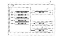
ここで、本実施形態に係るHMD1の機能構成等について、図4を参照して説明する。図4は、本実施形態に係るHMD1の機能構成を示す説明図である。[HMD function configuration]
Here, a functional configuration and the like of the
図4に示すように、このHMD1におけるCCDセンサ2は、撮像手段201を有している。この撮像手段201は、観察者Pの眼のうち少なくとも一部を撮像する。そして、撮像手段201は、制御部110にその撮像データを供給することとなる。 As shown in FIG. 4, the
そして、HMD1における制御部110は、開閉状態検知手段202と、睡眠検知手段203と、所定時間決定手段204と、画像記憶手段205と、表示制御手段206と、を有している。HMD1の制御部110において、後述のCPU101が所定の情報処理プログラムを実行することによって、開閉状態検知手段202、睡眠検知手段203、所定時間決定手段204、画像記憶手段205、表示制御手段206として制御部110が機能することとなる。 The
開閉状態検知手段202は、撮像手段201による撮像領域内における画像データに基づいて、観察者の眼の開閉状態を検知する。 The open / closed
睡眠検知手段203は、開閉状態検知手段202によって検知された観察者の眼の開閉状態(開閉時間の比)に基づいて、観察者の睡眠を検知する。 The
所定時間決定手段204は、睡眠検知手段203によって検知された観察者の睡眠状態に応じた所定時間を決定する。 The predetermined
画像記憶手段205は、上述したように所定の情報処理プログラムを実行するCPU101とRAM103とVRAM105とフラッシュメモリ102が相当し、表示手段207に表示されている画像を主にフラッシュメモリ102に記憶する。特に、画像記憶手段205は、表示されている入力画像を逐次記憶することとなり、睡眠検知手段203によって観察者Pの睡眠が検知された時点の所定時間前から睡眠検知時点までに表示されていた画像を少なくとも事前に記憶する。 The
表示制御手段206は、表示手段207に画像を表示させる制御を行う。特に、表示制御手段206は、睡眠検知手段203によって観察者の睡眠が検知された後にその観察者の睡眠が検知されなくなったときには、少なくともその観察者の睡眠が検知された時点の所定時間前から当該観察者の睡眠が検知された時点までに表示された画像を含む画像を表示手段207に表示させる制御を行う。 The
このHMD1における操作スイッチ7は、観察者によって操作可能な操作手段208を有している。 The operation switch 7 in the
また、このHMD1における光走査部10は、表示手段207として機能する。この表示手段207は、外光を透過しつつ、画像情報(表示情報)に応じた画像光を観察者の眼に投射してその観察者に画像光に応じた画像を視認させる。 The
ここで、本実施形態に係るHMD1における機能について、図5及び図6を参照して説明する。図5及び図6は、本実施形態に係るHMD1の機能を示す説明図である。 Here, functions of the
このHMD1においては、観察者Pの眼の開閉状態によって観察者Pが睡眠状態であるか否かが判定可能である。図5(A)に示すように、観察者Pの眼の開閉時間の比が所定比以上である場合には、覚醒状態と判定され、観察者Pの眼の開閉時間の比が所定比未満である場合には、睡眠状態と判定される。 In this HMD1, it is possible to determine whether or not the observer P is in a sleep state based on the open / closed state of the eyes of the observer P. As shown in FIG. 5A, when the ratio of the opening and closing times of the eyes of the observer P is equal to or greater than a predetermined ratio, it is determined that the person is awake and the ratio of the opening and closing times of the eyes of the observer P is less than the predetermined ratio. If it is, it is determined to be a sleep state.
また、本実施形態においては、撮像した画像から上下の瞼間の距離又は上下の瞼に挟まれた瞳の面積に基づいて睡眠状態であるか否かを判定するが、これに限らず、例えば、この瞼間の距離や瞳の面積を、各個人のそれらの最大値と比較した情報に基づいて、睡眠状態であるか否かを判定してもよく、その瞼の距離や瞳の面積などに個人差がある場合であっても睡眠状態を正確に検知し易く、更には、眼の細い(小さい)人に対して睡眠状態を正確に検知し易くなる。 Further, in the present embodiment, it is determined whether or not a sleeping state is based on the distance between the upper and lower eyelids or the area of the pupil sandwiched between the upper and lower eyelids from the captured image. You may decide whether you are sleeping or not based on information comparing the distance between the intercostals and the area of the pupils with their maximum values for each individual, such as the distance of the intercostals and the area of the pupils, etc. Even if there is a difference between individuals, it is easy to accurately detect the sleep state, and furthermore, it becomes easy to accurately detect the sleep state for a person with small eyes (small).
また、上述した実施形態においては、観察者Pの眼が開いている時間と閉じている時間との比が所定比未満である場合に睡眠状態となったと検知したが、これに限らず、例えば、観察者Pの眼の開閉周期や開閉量によって睡眠状態となったと検知してもよい。特に、詳しく第二の実施形態で説明する睡眠状態1(うとうと状態)となったことを検知するのに用いてもよい。また、観察者Pの眼を半開きにして睡眠状態に入る場合もあるため、観察者Pの眼がある程度閉じた状態(所定の開閉面積の比であり、所謂「半開き」の状態)でその開閉周期が極端に長い場合も睡眠状態としてもよい。 In the above-described embodiment, the sleep state is detected when the ratio between the time when the eyes of the observer P are open and the time when the eyes are closed is less than a predetermined ratio. The sleep state may be detected based on the opening / closing period and the opening / closing amount of the eyes of the observer P. In particular, it may be used to detect that the sleep state 1 (final state) described in detail in the second embodiment is reached. In addition, since the observer P's eyes may be half-opened to enter a sleeping state, the observer P's eyes are closed to some extent (a ratio of a predetermined opening / closing area, a so-called “half-open” state). It is good also as a sleep state also when a period is extremely long.
また、このように検知された状態に応じて、以下のように画像が記憶され、再生されることとなる。即ち、図6(A)左図に示すように、まず覚醒状態であると判定された状態で、所定の動画像(映像)コンテンツの画像(信号、情報、データ)が入力されるとその画像の記憶が開始され、所定時間Taまで順次入力される画像の記憶が継続して行われる。その後、所定時間Taの経過後が覚醒状態であれば、図6(A)右図に示すように、古い画像から逐次消去されることで、所定時間Ta前から現在までの記憶が少なくとも保持される。なお、現在の所定時間Ta前よりも前に表示されていた画像が記憶されるようにしてもよく、その場合は、所定時間Ta前の画像に関する情報(記憶位置)が記憶され、この情報に基づいて、改めて、この動画像コンテンツを再生する場合に前記所定時間Ta前からの画像再生が容易となる。 Further, according to the state detected in this way, an image is stored and reproduced as follows. That is, as shown in the left diagram of FIG. 6A, when an image (signal, information, data) of a predetermined moving image (video) content is input in a state where it is first determined to be an awakened state, the image is displayed. Is started, and images that are sequentially input until a predetermined time Ta are continuously stored. After that, if the predetermined time Ta has elapsed, as shown in the right figure of FIG. 6 (A), at least the memory from the predetermined time Ta to the present is retained by sequentially deleting old images. The Note that an image displayed before the current predetermined time Ta may be stored. In this case, information (storage position) regarding the image before the predetermined time Ta is stored, and this information is stored in this information. Based on this, when this moving image content is reproduced again, it becomes easier to reproduce the image from the predetermined time Ta.
また、覚醒状態から睡眠状態になったと判定された場合には、図6(B)に示すように、睡眠状態となったと検知された時点から所定時間Ta前までの時間に記憶された画像の消去が禁止され、その後、図6(C)に示すように、時間が経過し、睡眠状態が継続されても、睡眠状態となったと検知された時点の所定時間Ta前から睡眠状態となったと検知された時点まで表示された画像の記憶が維持される。そして、睡眠状態から覚醒状態となった時点以降に、自動的に又は画像の再生指示により、その睡眠状態となったと検知された時点の所定時間Ta前からの画像が順次再生されることとなる。なお、睡眠状態となったと検知されてからの画像は、フラッシュメモリ102等の記憶手段の残りの容量に応じて引き続き記憶しても、記憶を止めても構わない。睡眠状態となったと検知されてからの画像を引き続き記憶する場合には、睡眠状態から覚醒状態となった時点以降に、改めて睡眠状態時に視聴できなかった画像も含めた再生指示があれば、その睡眠状態となったと検知された時点の所定時間Ta前の画像から睡眠状態となった後に記憶された画像まで順次再生されることとなる。 In addition, when it is determined that the sleep state is changed from the awake state, as shown in FIG. 6B, the image stored in the time from when the sleep state is detected until the predetermined time Ta is detected. After the erasure is prohibited, as shown in FIG. 6 (C), even if the time has elapsed and the sleep state is continued, the sleep state has been entered from a predetermined time Ta before the sleep time is detected. The memory of the displayed image is maintained until the detected time. Then, after the time point when the sleep state is changed to the awake state, the images from the predetermined time Ta before the time point when the sleep state is detected automatically or by the image reproduction instruction are sequentially reproduced. . It should be noted that the image after it is detected that the sleeping state is detected may be continuously stored or stopped depending on the remaining capacity of the storage means such as the
[制御動作]
次に、図7及び図8のフローチャートを参照して、HMD1の動作について説明する。図7及び図8は、HMD1において実行される処理の動作を示すフローチャートである。特に、図7に示すメイン処理は、HMD1の電源がオンされた際に制御部110によって実行される。[Control action]
Next, the operation of the
本実施形態のHMD1において、制御部110は、フラッシュメモリ102内に記憶している情報処理プログラムを実行することによって、上記した開閉状態検知手段202、睡眠検知手段203、所定時間決定手段204、画像記憶手段205、表示制御手段206等として機能することとなる。 In the
[メイン処理]
最初に、図7に示すように、HMD1に電源が投入されると、制御部110は、初期設定を行う(ステップS11)。この処理において、制御部110は、RAMアクセス許可、作業領域の初期化等を実行する。この処理が終了した場合には、ステップS12に処理を移す。[Main processing]
First, as shown in FIG. 7, when the
ステップS12において、制御部110は、再生中であるか否かを判定する。この処理において、制御部110は、インターフェース104を介する画像信号の入力の有無に応じて、HMD1において動画像コンテンツを再生している最中であるか否かを判定する。制御部110は、再生中であると判定すると(ステップS12:YES)、ステップS13に処理を移す。一方、制御部110は、再生中ではないと判定すると(ステップS12:NO)、ステップS13、ステップS14を実行することなく、ステップS15に処理を移す。 In step S12, the
ステップS13において、制御部110は、今現在再生している画像を保存(記憶)する。具体的には、制御部110は、逐次、インターフェース104から画像信号を受信し、一度VRAM105に画像データとして展開し、その画像データに応じた画像信号を光走査部10に送信する一方で、この画像データを、VRAM105からフラッシュメモリ102又はRAM103に記憶する。制御部110は、このような処理を実行することによって、画像記憶手段205、表示制御手段206として機能する。この処理が終了した場合には、ステップS14に処理を移す。 In step S13, the
また、本実施形態においては、覚醒状態から睡眠状態となった場合でも、入力されている画像の記憶を継続するとともに、その画像の再生を一時停止しない構成であったが、これに限らず、例えば、画像の記憶や再生を一時停止してもよい。 Further, in the present embodiment, even when the sleep state is changed from the awake state, the input image is continuously stored and the reproduction of the image is not paused. For example, image storage and playback may be paused.
ステップS14において、制御部110は、睡眠検知処理を実行する。詳しくは図8を用いて後述するが、制御部110は、観察者Pの眼の開閉状態を一定時間毎にサンプリングし、検知することによって、観察者Pが睡眠状態となっているか否かを検知することとなる。この処理が終了した場合には、ステップS15に処理を移す。 In step S14, the
ステップS15において、制御部110は、操作検知処理を実行する。この処理において、制御部110は、操作手段208としての操作スイッチ7の操作に応じた制御を行う。具体的には、制御部110は、操作スイッチ7の操作に応じて画像を再生する場合には、その指定された画像を再生し、同じように、制御部110は、操作スイッチ7の操作に応じて、再生を停止する場合には、その指定された画像の再生を停止することとなる。この処理が終了した場合には、ステップS16に処理を移す。 In step S15, the
ステップS16において、制御部110は、その他制御処理を実行する。そして、制御部110は、電源オフであるか否かを判定する(ステップS20)。この処理において、制御部110は、電源スイッチSWの操作等に応じて、電源オフであるか否かを判定することとなる。制御部110は、電源オフであると判定すると(ステップS20:YES)、メイン処理を終了する。一方、制御部110は、電源オフではないと判定すると(ステップS20:NO)、再度、ステップS12に処理を移す。これによって、制御部110は、電源オフとなるまで、ステップS12からステップS16を繰り返し実行することとなる。 In step S16, the
[睡眠検知処理]
図7のステップS14において実行されるサブルーチンについて図8を用いて説明する。[Sleep detection processing]
The subroutine executed in step S14 in FIG. 7 will be described with reference to FIG.
最初に、図8に示すように、制御部110は、瞬き情報サンプリング処理を実行する(ステップS31)。この処理において、制御部110は、撮像手段201としてのCCDセンサ2から観察者Pの眼を撮像した画像信号を受け取り、観察者Pの眼の画像データを抽出し、取得する。そして、制御部110は、観察者Pの眼の画像データから観察者Pの眼が開放状態であるか閉鎖状態であるかを例えば画像1フレームにおいて判定する。そして、詳しく後述するように、制御部110は、十分な時間が経過するまで一定時間毎に、繰り返し上述した判定を行い、観察者Pの眼の開閉時間の比を計数し、RAM103の所定領域にセットすることとなる。この処理が終了した場合には、ステップS32に処理を移す。 First, as shown in FIG. 8, the
そして、制御部110は、上述した判定を行うのに十分な時間が経過されたか否かを判定する(ステップS32)。この処理において、制御部110は、上述した判定を行うのに十分な時間が経過されたと判定すると(ステップS32:YES)、ステップS33に処理を移す。一方、制御部110は、上述した判定を行うのに十分な時間が経過されていないと判定すると(ステップS32:NO)、本サブルーチンの処理を終了する。 Then, the
このように、制御部110は、観察者Pの眼の開閉状態を検知することとなる。制御部110は、このような処理を実行することによって、開閉状態検知手段202として機能する。 Thus, the
ステップS33において、制御部110は、観察者Pの眼の開閉時間の比が所定比以上であるか否かを判定する。この処理において、制御部110は、ステップS31においてサンプリングした観察者Pの眼の開閉時間の比と、予め設定されている所定比とを読み出し、比較することによって、観察者Pの眼の開閉時間の比が所定比以上であるか否かを判定することとなる。なお、この開閉時間の比は、大きくなると眼を開いている比率が長くなるように設定されており、所定比以上であると判定されると、観察者Pが覚醒状態であると認識され、所定比未満であると判定されると、観察者Pが睡眠状態であると認識される。 In step S <b> 33, the
制御部110は、観察者Pの眼の開閉時間の比が所定比以上であると判定すると(ステップS33:YES)、ステップS34に処理を移す。一方、制御部110は、観察者Pの眼の開閉時間の比が所定比未満であると判定すると(ステップS33:NO)、ステップS36に処理を移す。 If the
このように、制御部110は、検知された観察者Pの眼の開閉状態(開閉時間の比)に基づいて、観察者Pの睡眠を検知することとなる。制御部110は、このような処理を実行することによって、睡眠検知手段203として機能する。 As described above, the
ステップS34において、制御部110は、所定時間Ta前より前の画像を記憶済みであるか否かを判定する。すなわち、制御部110は、所定時間Ta前より前に再生された画像データがフラッシュメモリ102又はRAM103に記憶されているか否かを判定する。この処理において、所定時間Ta前より前の画像を記憶済みであると判定すると(ステップS34:YES)、制御部110は、所定時間Ta前より前に再生された画像データをフラッシュメモリ102又はRAM103にから消去して、その画像を消去する(ステップS35)。このステップS35の処理が終了したとき、又は所定時間Ta前より前の画像を記憶済みではないと判定したとき(ステップS34:NO)、本サブルーチンを終了する。 In step S34, the
このように、制御部110は、所定時間Ta前から現在までに表示された画像を記憶する。制御部110は、このような処理を実行することによって、画像記憶手段205として機能する。 As described above, the
なお、本実施形態においては、再生されている画像を逐次記憶し、一方で現在再生している時点の所定時間Ta前よりも前の画像を消去するようにしたが、これに限らず、例えば、現在再生している時点の所定時間Ta前よりも前の画像を消去せずに記憶しておくようにしてもよい。 In the present embodiment, the images being reproduced are sequentially stored, and on the other hand, the images before a predetermined time Ta before the current reproduction are erased. Alternatively, an image before a predetermined time Ta before the current playback time may be stored without being erased.
一方、ステップS36において、制御部110は、観察者Pの眼の開閉時間の比が所定比未満の状態で所定時間以上継続しているか否かを判定する。この処理において、この所定比未満の状態が所定時間以上継続していると判定すると(ステップS36:YES)、制御部110は、動画像コンテンツの再生を中止する(ステップS37)。このステップS37の処理、又は所定比未満の状態が所定時間以上継続していないと判定したとき(ステップS36:NO)、本サブルーチンを終了する。 On the other hand, in step S <b> 36, the
このように、制御部110は、観察者Pの睡眠が検知された時点の所定時間Ta前に表示されていた画像から、その観察者Pの睡眠が検知された時点までの画像を少なくとも含む画像を記憶する。制御部110は、このような処理を実行することによって、画像記憶手段205として機能する。 As described above, the
また、制御部110は、睡眠状態から覚醒状態を検知したり、再生指示があったりした場合には、このように記憶が維持された画像データが再生されることとなり、観察者が画像の視認中に睡眠状態となった場合であっても、その後、睡眠状態ではなくなったときに、睡眠状態となった時に視認できなかった画像、特に眠くなり始めた頃の画像を改めて視認するときの煩雑さを抑制することができる。 In addition, when the
[第二の実施形態]
上述した実施形態においては、観察者Pの眼の開閉状態に基づいて、覚醒状態と睡眠状態との2段階の検知を行ったが、これに限らず、例えば、睡眠状態でも睡眠度合いを検知してもよい。また、この睡眠度合いによって、再生を開始させる時間を変化させてもよい。[Second Embodiment]
In the above-described embodiment, the two-stage detection of the awake state and the sleep state is performed based on the open / closed state of the eyes of the observer P. However, the present invention is not limited to this. May be. Moreover, you may change the time which starts reproduction | regeneration according to this sleep degree.
また、上述した実施形態においては、再生を開始させる時間の基準や、観察者Pの睡眠が検知される基準が予め一定の値に設定されていたが、これに限らず、例えば、観察者Pの操作に応じて変化可能に設定してもよい。 In the above-described embodiment, the reference for the time to start reproduction and the reference for detecting the sleep of the observer P are set to a predetermined value in advance. It may be set to be changeable in accordance with the operation.
このような構成の具体的な一実施形態について図5、図6、図9及び図10を用いて以下に説明する。なお、本実施形態においては、発明の理解を容易とするために、異なる構成、処理について主に説明をし、同じような構成、処理については説明を省略する。 A specific embodiment of such a configuration will be described below with reference to FIGS. 5, 6, 9 and 10. In the present embodiment, in order to facilitate understanding of the invention, different configurations and processes are mainly described, and descriptions of similar configurations and processes are omitted.
[HMD機能構成]
ここで、本実施形態に係るHMD1の機能構成等について、図9を参照して説明する。図9は、本実施形態に係るHMD1の機能構成を示す説明図である。[HMD function configuration]
Here, a functional configuration and the like of the
図9に示すように、HMD1における制御部110は、上述した実施形態以外に、所定時間設定手段209と、睡眠検知設定手段210と、を有している。HMD1の制御部110において、後述のCPU101が所定の情報処理プログラムを実行することによって、上述した実施形態以外に、所定時間設定手段209、睡眠検知設定手段210として制御部110が機能することとなる。 As illustrated in FIG. 9, the
睡眠検知手段203は、開閉状態検知手段202によって検知された観察者の眼の開閉状態(開閉時間の比)に基づいて、観察者の睡眠度合いを検知する。 The
所定時間決定手段204は、睡眠検知手段203によって検知された観察者の睡眠度合いに基づいて所定時間を決定する。 The predetermined
所定時間設定手段209は、操作手段208の操作に応じて所定時間の基準を設定する。 The predetermined
睡眠検知設定手段210は、操作手段208の操作に応じて、睡眠検知手段203によって観察者の睡眠や睡眠度合いが検知される基準を設定する。 The sleep
ここで、本実施形態に係るHMD1における機能について、図5及び図6を参照して説明する。図5及び図6は、本実施形態に係るHMD1の機能を示す説明図である。 Here, functions of the
このHMD1においては、図5(B)に示すように、観察者Pの眼の開閉時間の比が第一比以上である場合には、覚醒状態と判定され、観察者Pの眼の開閉時間の比が第一比未満第二比以上である場合には、睡眠状態1(うとうと状態)と判定され、観察者Pの眼の開閉時間の比が第二比未満である場合には、睡眠状態2(熟睡状態)と判定される。 In this HMD1, as shown in FIG. 5B, when the ratio of the opening / closing time of the eyes of the observer P is equal to or higher than the first ratio, it is determined that the eyes are awake and the opening / closing time of the eyes of the observer P If the ratio is less than the first ratio and greater than or equal to the second ratio, it is determined that the sleep state is 1 (the final state), and if the ratio of the eye open / close time of the observer P is less than the second ratio, It is determined as state 2 (deep sleep state).
また、睡眠状態2(熟睡状態)から覚醒状態になったと判定された場合には、図6(D)に示すように、その睡眠状態2となったと検知された時点の第一時間Tb前から画像から再生される。一方、睡眠状態1(うとうと状態)から覚醒状態になったと判定された場合には、図6(E)に示すように、覚醒状態となった時点から、睡眠状態1となった時点の第二時間Tc前の画像から再生が行われる。この第二時間Tcは、第一時間Tbよりも短く、睡眠状態1(うとうと状態)から覚醒状態となった場合には、睡眠状態2(熟睡状態)から覚醒状態となった場合よりも遡って再生する時間が短くなる。 When it is determined that the sleep state 2 (deep sleep state) has changed to the awake state, as shown in FIG. 6D, from the time before the first time Tb when the
さらに、睡眠状態2となったと検知された時点からこの検知状態が所定時間T2だけ経過したとき(図6(D)参照)、動画像コンテンツの再生を停止する。同様に睡眠状態1なったと検知された時点からこの検知状態が所定時間T1だけ経過したとき(図6(E)参照)、動画像コンテンツの再生を停止する。所定時間T1,T2は、睡眠状態が継続するか否かを判定するための期間であり、この期間が経過したときに睡眠状態から覚醒状態へ移行する可能性が低いと判断して動画像コンテンツの再生を停止している。また、熟睡状態(睡眠状態2)から覚醒状態になるよりもうとうと状態(睡眠状態1)から覚醒状態になる可能性が高いため、所定時間T1を所定時間T2よりも長くしている。なお、動画像コンテンツの再生を停止した後に電源オフを行うようにしてもよい。また、所定時間T1,T2は同一時間として、処理を簡素化することもできる。 Furthermore, when this detection state has elapsed for a predetermined time T2 from the time when it is detected that the
また、第一時間Tbは、動画像コンテンツを記憶するフラッシュメモリ102やRAM103の記憶容量の状態に応じて可変にすることが望ましい。また、睡眠状態1,2を検知した後は、再生の停止まで又は電源オフまで再生中の画像を記憶することが望ましいが、所定時間後まで記憶するようにしてもよく、また、フラッシュメモリ102の記憶容量の残量や電池残量(HMD1を電池で動かした場合)に応じた時間だけ記憶するようにしてもよい。 The first time Tb is preferably variable according to the storage capacity of the
[メイン処理]
ステップS15において、制御部110は、操作検知処理を実行する。この処理において、制御部110は、操作手段208としての操作スイッチ7の操作に応じた制御を行う。具体的には、制御部110は、操作スイッチ7の操作に応じて、睡眠度合いの検知を行う基準となる観察者Pの眼の開閉時間の比や、その睡眠度合いに対応して覚醒時となってから再生の基準となる時間(第一時間Tb又は第二時間Tc)の設定を行う。これによって、制御部110は、操作手段208の操作に応じて、覚醒時において再生するための所定時間の基準と、観察者Pの睡眠や睡眠度合いが検知される基準とを設定することとなる。制御部110は、このような処理を実行することによって、所定時間設定手段209、睡眠検知設定手段210として機能する。この処理が終了した場合には、ステップS16に処理を移す。[Main processing]
In step S15, the
このように、観察者Pの操作に応じて、所定時間、睡眠の検知、睡眠度合いの検知の基準を、観察者Pの意図するように設定することができ、簡便である。 Thus, according to the operation of the observer P, the reference for detecting the sleep and the sleep degree for a predetermined time can be set as intended by the observer P, which is convenient.
[睡眠検知処理]
図7のステップS14において実行されるサブルーチンについて図10を用いて説明する。[Sleep detection processing]
The subroutine executed in step S14 in FIG. 7 will be described with reference to FIG.
図10に示すように、制御部110は、ステップS32においてサンプリングするのに十分な時間が経過されたと判定されると(ステップS32:YES)、ステップS40に処理を移す。 As shown in FIG. 10, when it is determined that the time sufficient for sampling has elapsed in step S32 (step S32: YES), the
ステップS40において、制御部110は、観察者Pの眼の開閉時間の比が第一比以上であるか否かを判定する。この処理において、制御部110は、ステップS31においてサンプリングした観察者Pの眼の開閉時間の比と、観察者Pの操作に応じて予め設定されている第一比とを読み出し、比較することによって、観察者Pの眼の開閉時間の比が第一比以上であるか否かを判定することとなる。なお、この開閉時間の比は、大きくなると眼を開いている比率が長くなるように設定されており、第一比以上であると判定されると、観察者Pが覚醒状態であると認識され、第一比未満であると判定されると、観察者Pが睡眠状態であると認識される。 In step S40, the
制御部110は、観察者Pの眼の開閉時間の比が第一比以上であると判定すると(ステップS40:YES)、ステップS41に処理を移す。一方、制御部110は、観察者Pの眼の第一比が所定比未満であると判定すると(ステップS40:NO)、ステップS43に処理を移す。 If the
ステップS41において、制御部110は、第一時間Tb前より前の画像を記憶済みであるか否かを判定する。すなわち、制御部110は、第一時間Tb前より前に再生された画像データがフラッシュメモリ102又はRAM103に記憶されているか否かを判定する。この処理において、制御部110は、第一時間Tb前より前の画像を記憶済みであると判定すると(ステップS41:YES)、第一時間Tb前より前に再生された画像データをフラッシュメモリ102又はRAM103にから消去して、その画像を消去する(ステップS42)。このステップS42の処理が終了したとき、又は第一時間Tb前より前の画像を記憶済みはでないと判定したとき(ステップS41:NO)、制御部110は、本サブルーチンを終了する。 In step S41, the
一方、ステップS43において、制御部110は、観察者Pの眼の開閉時間の比が第二比以上であるか否かを判定する。この処理において、制御部110は、ステップS31においてサンプリングした観察者Pの眼の開閉時間の比と、観察者Pの操作に応じて予め設定されている第二比とを読み出し、比較することによって、観察者Pの眼の開閉時間の比が第二比以上であるか否かを判定することとなる。なお、この開閉時間の比は、大きくなると眼を開いている比率が長くなるように設定されており、第一比未満第二比以上であると判定されると、観察者Pが睡眠状態1(うとうと状態)であると認識され、第二比未満であると判定されると、観察者Pが睡眠状態2(熟睡状態)であると認識される。 On the other hand, in step S43, the
制御部110は、観察者Pの眼の開閉時間の比が第二比以上であると判定すると(ステップS43:YES)、ステップS47に処理を移す。一方、制御部110は、観察者Pの眼の第二比が所定比未満であると判定すると(ステップS43:NO)、ステップS44に処理を移す。 If the
ステップS44において、制御部110は、観察者Pの眼の開閉時間の比が第一比未満の状態が時間T1継続したか否かを判定する。すなわち、観察者Pが睡眠状態1(うとうと状態)であると判定してから所定時間T1を経過したか否かを判定する。この処理において、所定時間T1を経過していないと判定すると(ステップS44:NO)、制御部110は、ステップS45に処理を移す。一方、ステップS44において、所定時間T1を経過したと判定すると(ステップS44:YES)、制御部110は、動画像コンテンツの再生を中止し(ステップS48)、本サブルーチンを終了する。 In step S44, the
ステップS45の処理において、制御部110は、睡眠状態1に移行した時点の第二時間Tc前よりも前の画像を記憶済みであるか否かを判定する(ステップS45)。すなわち、観察者Pの眼の開閉時間の比が第一比未満になったことを検知した時点の第二時間Tc前よりも前に再生された画像データがフラッシュメモリ102又はRAM103に記憶されているか否かを判定する。第二時間Tc前よりも前の画像を記憶済みであると判定すると(ステップS45:YES)、制御部110は、睡眠状態2に移行した時点の第二時間Tc前よりも前に再生された画像データをフラッシュメモリ102又はRAM103から消去し、その画像を消去する(ステップS46)。このステップS46の処理が終了したとき、又は第二時間Tc前よりも前の画像を記憶済みではないと判定すると(ステップS45:NO)、本サブルーチンを終了する。 In the process of step S45, the
ステップS47において、制御部110は、観察者Pの眼の開閉時間の比が第二比未満の状態が時間T2継続したか否かを判定する。すなわち、観察者Pが睡眠状態2(熟睡状態)に移行した時点から所定時間T2を経過したか否かを判定する。この処理において、所定時間T2を経過したと判定すると(ステップS47:YES)、制御部110は、動画像コンテンツの再生を中止する(ステップS48)。このステップS48の処理が終了したとき、又は所定時間T2を経過したと判定したとき(ステップS47:NO)、本サブルーチンを終了する。なお、再生停止後、フラッシュメモリ102又はRAM103に画像データを記憶した状態で、電源オフの処理を行うようにしてもよい。その際、制御部110は、睡眠状態のために電源オフを行った旨の情報もフラッシュメモリ102等に記憶するようにし、次回の電源オン時に、睡眠状態によって電源オフが行われた旨を表示するようにしてもよい。 In step S47, the
このように、制御部110は、睡眠検知手段203として機能して、検知された観察者Pの眼の開閉状態(開閉時間の比)に基づいて、観察者Pの睡眠や睡眠度合いを検知することとなる。 As described above, the
開閉時間の比が第一比以上のとき、制御部110は、睡眠状態ではないことを検知し、画像記憶手段205として機能して、第一時間Tb(所定時間)前から現在までに表示された画像を記憶する。 When the ratio of the open / close time is equal to or higher than the first ratio, the
また、開閉時間の比が第一比未満でかつ第二比以上のとき、制御部110は、観察者Pが睡眠状態1であることを検知し、画像記憶手段205として機能として、睡眠状態1であると検知された時点の第二時間Tc前に表示されていた画像から、その観察者Pの睡眠が検知された時点までの画像を少なくとも含む画像を記憶する。 When the ratio of the opening and closing times is less than the first ratio and greater than or equal to the second ratio, the
また、開閉時間の比が第二比未満のとき、制御部110は、観察者Pが睡眠状態2であることを検知し、画像記憶手段205として機能として、睡眠状態2であると検知された時点の第一時間Tb(>第二時間Tc)前に表示されていた画像から、その観察者Pの睡眠が検知された時点までの画像を少なくとも含む画像を記憶する。 In addition, when the ratio of the open / close time is less than the second ratio, the
このように、制御部110は、検知された観察者の睡眠度合いに基づいて、所定時間(第一時間Tbにするか第二時間Tcにするか)を決定することとなる。制御部110は、このような処理を実行することによって、所定時間決定手段204として機能する。このため、観察者Pの睡眠度合いに応じた位置から再生開始することとなり、簡便である。 As described above, the
例えば、制御部110は、睡眠状態から覚醒状態への移行を検知したり、再生指示を検知した場合には、このように記憶が維持された画像が再生されることとなり、観察者は画像を視認している途中で睡眠状態となった場合であっても、その後、睡眠状態ではなくなったときに、睡眠状態となった時に視認できなかった画像、特に眠くなり始めた頃の画像を改めて視認するときの煩雑さを抑制することができる。 For example, when the
[その他の実施形態]
なお、本実施形態においては、睡眠状態1、睡眠状態2から覚醒状態となったときに、それらの睡眠状態となったと検知した時点の所定時間(第一時間Tb又は第二時間Tc)前に表示されていた画像から、自動的に、又は、表示指示に応じて順次表示されるようにしたが、これに限らず、例えば、睡眠状態から覚醒状態となった場合には、その後一定時間が経過してから画像の再生を開始してもよい。具体的には、熟睡が推測される睡眠状態2から覚醒状態となった場合には、すぐに画像が表示されるよりも、観察者Pの再生指示の操作に応じて、又は、一定時間経過した後に、再生されたほうが好ましい。一方、睡眠状態2となることなく、睡眠状態1から覚醒状態となった場合には、その睡眠状態1となった時点の第二時間Tc前(所定時間前)に表示されていた画像から再生を開始させるようにしてもよい。[Other Embodiments]
In the present embodiment, when the
また、上述した実施形態においては、睡眠状態となった場合に再生していた画像を停止させることなく、継続して再生させていたが、これに限らず、例えば、睡眠状態2(熟睡状態)となった場合には、即座に覚醒状態となる可能性が相対的に低いため、例えば、記憶可能な一定時間だけ再生させるとともに、その一定時間の画像も記憶し、未だ睡眠状態2が続く場合には、HMD1の電源などを停止(スタンバイ)させても好適である。一方、睡眠状態2となることなく、睡眠状態1となった場合には、即座に覚醒状態となる可能性が相対的に高いため、覚醒状態となったらすぐ再生できるように画像の再生を一時停止させても好適である。 Further, in the above-described embodiment, the image that has been reproduced when the sleep state is reached is continuously reproduced without being stopped. However, the present invention is not limited thereto, and for example, the sleep state 2 (deep sleep state) In such a case, since it is relatively unlikely to immediately become an awakened state, for example, the image is reproduced only for a predetermined period of time that can be memorized, and the image for the predetermined period is also stored, and the
また、上述した実施形態においては、睡眠状態1、睡眠状態2等の睡眠度合いの種類に基づいて、睡眠状態を検知した時点から遡って再生する所定時間を、第一時間Tb、第二時間Tcのいずれかとしたが、これに限らず、例えば、睡眠状態1の長さに基づいて、睡眠状態を検知した時点から遡って再生する所定時間を決定してもよい。また、例えば、睡眠状態2の期間に基づいて第一時間Tbを変更可能に決定してもよい。もちろん、それらの組合せであってもよい。また、例えば、睡眠検知時以前の睡眠度合い判定期間、又は、睡眠状態1(うとうと状態)の期間において、眼の開閉面積の比の平均値に応じて所定時間を決めてもよい。具体的には、上述した期間において眼の開き具合が小さいほど所定時間を長くするように構成してもよい。また、例えば、目の開閉周期や上下の瞼の間の距離の平均などに基づいて所定時間を変更可能に決定してもよい。つまり、制御部110は、観察者Pの眼の開閉周期や開閉量などに基づいて、観察者Pの睡眠度合いを検知できればよい。 Moreover, in embodiment mentioned above, based on the kind of sleep degree, such as the
また、上述した実施形態においては、睡眠状態1と睡眠状態2とを相互に独立して制御を行ったが、これに限らず、例えば、覚醒状態、睡眠状態1、睡眠状態2が相関する制御を行ってもよい。 Moreover, in embodiment mentioned above, although the
なお、上述した実施形態においては、HMD1自体に画像データ自体を保存したが、これに限らず、例えば、HMD1自体に次に再生する時間を記憶してもよい。この場合においては、睡眠状態となったことを検知したときには、画像の再生を一時停止し、睡眠状態となっているか否かの検知が継続され、一定時間後、まだ睡眠状態ならば、画像の再生を停止し、電源など装置も停止又はスタンバイとしてもよい。また、睡眠状態2から睡眠状態1となった場合には、画像の再生を再開し、その再生している画像を記憶するが、睡眠状態2から覚醒状態となった場合に、睡眠状態2となった時点の所定時間前(第一時間Tb前)に表示されていた画像から再生を開始するため、画像の記憶を停止させてもよい。 In the above-described embodiment, the image data itself is stored in the
また、例えば、HMD1以外の外部装置に画像データ自体が記憶されており、HMD1から再生箇所(例えば、再生時間等)を指示することによって、画像データがHMD1に供給されるように構成してもよい。 Further, for example, the image data itself is stored in an external device other than the
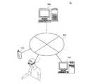
この場合においては、例えば、図11に示すように、HMD1が情報閲覧システムS1に含まれた構成であり、その他に管理サーバ300、パーソナルコンピュータ310及び携帯型端末装置312が、ネットワーク網302に接続され、相互に通信可能に構成する。 In this case, for example, as shown in FIG. 11, the
HMD1は、図9に示すように、画像記憶指示手段213を有しており、管理サーバ300(外部装置)に対して、睡眠検知手段203によって観察者の睡眠が検知された時点において表示させていた画像よりも所定時間前における画像の情報を一定時間記憶する旨の指示を行う。 As shown in FIG. 9, the
また、このHMD1における通信制御回路9は、受信手段211と、送信手段212とを有している。この受信手段211は、ネットワーク網302を介して通信可能な管理サーバ300(外部装置)から画像の情報を受信する。一方、送信手段212は、画像記憶指示手段213によって指示された指示を管理サーバ300に送信する。 Further, the
管理サーバ300は、各種のコンテンツに関する情報を管理する装置である。特に、管理サーバ300は、コンテンツに対応する画像データや再生する時間などを観察者毎に記憶する。 The
これによって、画像データ自体や再生開始する時間などを管理サーバ300等の外部装置に記憶することができ、HMD1のデータ記憶領域の節約を行うことができる。 As a result, the image data itself and the playback start time can be stored in an external device such as the
また、上述した実施形態においては、外光を透過しつつ、コンテンツ情報に応じた画像光を観察者Pの眼に投射するシースルー型のヘッドマウントディスプレイを採用したが、これに限らず、例えば、外光を透過しないヘッドマウントディスプレイを採用してもよい。 In the above-described embodiment, a see-through head mounted display that projects image light according to content information onto the eyes of the observer P while transmitting external light is used. You may employ | adopt the head mounted display which does not permeate | transmit outside light.
1 HMD
2 CCDセンサ
110 制御部1 HMD
2
Claims (8)
Translated fromJapanese観察者の眼の開閉状態を検知する開閉状態検知手段と、
前記開閉状態検知手段によって検知された観察者の眼の開閉状態に基づいて、観察者の睡眠を検知する睡眠検知手段と、
前記表示手段に画像を表示させる制御を行い、前記睡眠検知手段によって観察者の睡眠が検知された後に当該観察者の睡眠が検知されなくなった場合、少なくとも当該観察者の睡眠が検知された時点の所定時間前から、当該観察者の睡眠が検知された時点までに表示されていた画像を含む画像を表示させうる制御を行う表示制御手段と、を備え、前記所定時間は観察者の睡眠状態に応じて決定されることを特徴とするヘッドマウントディスプレイ。In a head mounted display provided with display means for projecting image light according to image information onto the eyes of an observer and allowing the observer to visually recognize an image according to the image light,
Open / closed state detecting means for detecting the open / closed state of the eyes of the observer;
Sleep detection means for detecting the sleep of the observer based on the open / closed state of the eye of the observer detected by the open / close state detection means;
When displaying the image on the display means, and when the sleep of the observer is no longer detected after the sleep of the observer is detected by the sleep detection means, at least when the sleep of the observer is detectedDisplay control means for performing control that can display an image including an image that has been displayed from the predetermined time before the point in time when the sleep of the observer is detected, and the predetermined time is in the sleep state of the observer A head-mounted display characterizedby being determined accordingly .
前記睡眠検知手段によって検知された観察者の睡眠度合いに基づいて、前記所定時間を決定する所定時間決定手段を備えたことを特徴とする請求項1に記載のヘッドマウントディスプレイ。The sleep detection means, based on the closed state of the eyes of the observer sensed by the open-close state detecting means,a sleep state ofthe observerto detect sleep degreeof the observer,
The head-mounted display according to claim 1, further comprising a predetermined time determination unit that determines the predetermined time based on a sleep level of the observer detected by the sleep detection unit.
前記操作手段の操作に応じて、前記所定時間の基準を設定する所定時間設定手段と、を備えたことを特徴とする請求項1から4のいずれかに記載のヘッドマウントディスプレイ。Operation means that can be operated by an observer;
5. The head mounted display according to claim 1, further comprising predetermined time setting means for setting a reference for the predetermined time in accordance with an operation of the operation means.
前記操作手段の操作に応じて、前記睡眠検知手段によって観察者の睡眠が検知される基準を設定する睡眠検知設定手段と、を備えたことを特徴とする請求項1から4のいずれかに記載のヘッドマウントディスプレイ。Operation means that can be operated by an observer;
The sleep detection setting means which sets the reference | standard by which the observer's sleep is detected by the sleep detection means according to the operation of the operation means is provided. Head mounted display.
前記外部装置に対して、前記睡眠検知手段によって観察者の睡眠が検知された時点の所定時間前に表示されていた画像から、当該観察者の睡眠が検知された時点までの画像の情報を少なくとも記憶する旨の指示を行う画像記憶指示手段と、を備えたことを特徴とする請求項1から6のいずれかに記載のヘッドマウントディスプレイ。Receiving means for receiving image information from an external device capable of communicating via a network;
At least information on images from the image displayed for a predetermined time before the time when the sleep of the observer is detected by the sleep detection unit to the time when the sleep of the observer is detected is provided to the external device. 7. The head mounted display according to claim 1, further comprising image storage instruction means for instructing storage.
Priority Applications (1)
| Application Number | Priority Date | Filing Date | Title |
|---|---|---|---|
| JP2009029086AJP5212155B2 (en) | 2009-02-10 | 2009-02-10 | Head mounted display |
Applications Claiming Priority (1)
| Application Number | Priority Date | Filing Date | Title |
|---|---|---|---|
| JP2009029086AJP5212155B2 (en) | 2009-02-10 | 2009-02-10 | Head mounted display |
Publications (2)
| Publication Number | Publication Date |
|---|---|
| JP2010187132A JP2010187132A (en) | 2010-08-26 |
| JP5212155B2true JP5212155B2 (en) | 2013-06-19 |
Family
ID=42767521
Family Applications (1)
| Application Number | Title | Priority Date | Filing Date |
|---|---|---|---|
| JP2009029086AExpired - Fee RelatedJP5212155B2 (en) | 2009-02-10 | 2009-02-10 | Head mounted display |
Country Status (1)
| Country | Link |
|---|---|
| JP (1) | JP5212155B2 (en) |
Families Citing this family (10)
| Publication number | Priority date | Publication date | Assignee | Title |
|---|---|---|---|---|
| JP5953714B2 (en)* | 2011-11-24 | 2016-07-20 | セイコーエプソン株式会社 | Device, head-mounted display device, device control method, and head-mounted display device control method |
| JP5482712B2 (en)* | 2011-04-08 | 2014-05-07 | ブラザー工業株式会社 | Image display device |
| JP5482711B2 (en)* | 2011-04-08 | 2014-05-07 | ブラザー工業株式会社 | Image display device |
| JP5936379B2 (en)* | 2012-02-07 | 2016-06-22 | シャープ株式会社 | Image display device |
| JP6376807B2 (en)* | 2014-04-02 | 2018-08-22 | キヤノン株式会社 | Display device, display control method, and program |
| JP6322659B2 (en)* | 2016-02-17 | 2018-05-09 | 株式会社コーエーテクモゲームス | Information processing program and information processing apparatus |
| AU2017225977C1 (en) | 2016-03-04 | 2023-08-03 | Magic Leap, Inc. | Current drain reduction in AR/VR display systems |
| US10698215B2 (en) | 2016-03-25 | 2020-06-30 | Magic Leap, Inc. | Virtual and augmented reality systems and methods |
| US11966055B2 (en) | 2018-07-19 | 2024-04-23 | Magic Leap, Inc. | Content interaction driven by eye metrics |
| KR20250052652A (en)* | 2023-10-12 | 2025-04-21 | 삼성전자주식회사 | Head mounted display device and control method thereof |
Family Cites Families (5)
| Publication number | Priority date | Publication date | Assignee | Title |
|---|---|---|---|---|
| JPH0934424A (en)* | 1995-07-21 | 1997-02-07 | Mitsubishi Electric Corp | Display system |
| JPH11249064A (en)* | 1998-03-04 | 1999-09-17 | Omron Corp | Head mounted display device |
| JP2004109995A (en)* | 2003-08-12 | 2004-04-08 | Toshiba Corp | Wearable information presenting apparatus and method, and storage medium |
| JP3862027B2 (en)* | 2005-01-25 | 2006-12-27 | 船井電機株式会社 | Broadcast signal reception system |
| JP4690301B2 (en)* | 2006-12-20 | 2011-06-01 | Necカシオモバイルコミュニケーションズ株式会社 | Television broadcast reception output device and program |
- 2009
- 2009-02-10JPJP2009029086Apatent/JP5212155B2/ennot_activeExpired - Fee Related
Also Published As
| Publication number | Publication date |
|---|---|
| JP2010187132A (en) | 2010-08-26 |
Similar Documents
| Publication | Publication Date | Title |
|---|---|---|
| JP5212155B2 (en) | Head mounted display | |
| JP5272827B2 (en) | Head mounted display | |
| US9652036B2 (en) | Device, head mounted display, control method of device and control method of head mounted display | |
| JP6602911B2 (en) | Display system and method | |
| JP5168161B2 (en) | Head mounted display | |
| JP5293025B2 (en) | Head mounted display | |
| JP5481890B2 (en) | Head mounted display device, image control method, and image control program | |
| WO2010073879A1 (en) | Head-mounted display | |
| JP6231541B2 (en) | Image projection device | |
| JP2009245392A (en) | Head mount display and head mount display system | |
| JP5742271B2 (en) | Head-mounted display device and method for controlling head-mounted display device | |
| JP2013110662A (en) | Device, head-mounted display device, control method for device, and control method for head-mounted display device | |
| JP2010151997A (en) | Presentation system and program for the same | |
| US20180184042A1 (en) | Video display device and control method | |
| JP2013114123A (en) | Transmission type display device, display method and display program | |
| JP2017122775A (en) | Image projection device | |
| JP2012203127A (en) | Head mounted display, method for controlling head mounted display and computer program for controlling head mounted display | |
| JP5742270B2 (en) | Head-mounted display device and method for controlling head-mounted display device | |
| JP2008089931A (en) | Image display device and image size changing method | |
| JP5272813B2 (en) | Head mounted display | |
| JP2010136263A (en) | Head-mounted display | |
| US20250220293A1 (en) | Head mount type information processing device, information processing method, and storage medium | |
| JP2010134152A (en) | Head-mounted display | |
| JP5482712B2 (en) | Image display device | |
| JP2010062715A (en) | Electronic still camera |
Legal Events
| Date | Code | Title | Description |
|---|---|---|---|
| A621 | Written request for application examination | Free format text:JAPANESE INTERMEDIATE CODE: A621 Effective date:20110921 | |
| A977 | Report on retrieval | Free format text:JAPANESE INTERMEDIATE CODE: A971007 Effective date:20121029 | |
| A131 | Notification of reasons for refusal | Free format text:JAPANESE INTERMEDIATE CODE: A131 Effective date:20121106 | |
| A521 | Request for written amendment filed | Free format text:JAPANESE INTERMEDIATE CODE: A523 Effective date:20121226 | |
| TRDD | Decision of grant or rejection written | ||
| A01 | Written decision to grant a patent or to grant a registration (utility model) | Free format text:JAPANESE INTERMEDIATE CODE: A01 Effective date:20130129 | |
| A61 | First payment of annual fees (during grant procedure) | Free format text:JAPANESE INTERMEDIATE CODE: A61 Effective date:20130211 | |
| R150 | Certificate of patent or registration of utility model | Ref document number:5212155 Country of ref document:JP Free format text:JAPANESE INTERMEDIATE CODE: R150 Free format text:JAPANESE INTERMEDIATE CODE: R150 | |
| FPAY | Renewal fee payment (event date is renewal date of database) | Free format text:PAYMENT UNTIL: 20160308 Year of fee payment:3 | |
| LAPS | Cancellation because of no payment of annual fees |