JP5209603B2 - Methods and apparatus for the treatment of functional uterine bleeding, endometrial pathologies, and cervical neoplasia by use of high intensity focused ultrasound energy - Google Patents
Methods and apparatus for the treatment of functional uterine bleeding, endometrial pathologies, and cervical neoplasia by use of high intensity focused ultrasound energyDownload PDFInfo
- Publication number
- JP5209603B2 JP5209603B2JP2009505639AJP2009505639AJP5209603B2JP 5209603 B2JP5209603 B2JP 5209603B2JP 2009505639 AJP2009505639 AJP 2009505639AJP 2009505639 AJP2009505639 AJP 2009505639AJP 5209603 B2JP5209603 B2JP 5209603B2
- Authority
- JP
- Japan
- Prior art keywords
- hifu
- probe
- patient
- energy
- tissue
- Prior art date
- Legal status (The legal status is an assumption and is not a legal conclusion. Google has not performed a legal analysis and makes no representation as to the accuracy of the status listed.)
- Expired - Fee Related
Links
- 238000011282treatmentMethods0.000titleclaimsdescription120
- 230000002357endometrial effectEffects0.000titleclaimsdescription47
- 238000002604ultrasonographyMethods0.000titleclaimsdescription38
- 238000000034methodMethods0.000titledescription71
- 206010028980NeoplasmDiseases0.000titledescription9
- 230000009826neoplastic cell growthEffects0.000titledescription6
- 230000007170pathologyEffects0.000titledescription6
- 206010046788Uterine haemorrhageDiseases0.000titledescription5
- 239000000523sampleSubstances0.000claimsdescription138
- 239000007788liquidSubstances0.000claimsdescription108
- 238000003384imaging methodMethods0.000claimsdescription106
- 210000003679cervix uteriAnatomy0.000claimsdescription98
- 210000004291uterusAnatomy0.000claimsdescription45
- 239000000463materialSubstances0.000claimsdescription28
- 210000001215vaginaAnatomy0.000claimsdescription25
- 238000003780insertionMethods0.000claimsdescription18
- 230000037431insertionEffects0.000claimsdescription18
- 239000002245particleSubstances0.000claimsdescription15
- 230000001225therapeutic effectEffects0.000claimsdescription15
- 239000003814drugSubstances0.000claimsdescription13
- 230000035515penetrationEffects0.000claimsdescription12
- 238000010521absorption reactionMethods0.000claimsdescription4
- 230000003444anaesthetic effectEffects0.000claimsdescription4
- OKTJSMMVPCPJKN-UHFFFAOYSA-NCarbonChemical compound[C]OKTJSMMVPCPJKN-UHFFFAOYSA-N0.000claimsdescription2
- 239000010439graphiteSubstances0.000claimsdescription2
- 229910002804graphiteInorganic materials0.000claimsdescription2
- 239000002480mineral oilSubstances0.000claimsdescription2
- 235000010446mineral oilNutrition0.000claimsdescription2
- 230000004044responseEffects0.000claimsdescription2
- 229940124597therapeutic agentDrugs0.000claims1
- 210000001519tissueAnatomy0.000description126
- 238000002560therapeutic procedureMethods0.000description109
- 230000003902lesionEffects0.000description24
- 210000004696endometriumAnatomy0.000description21
- 238000002271resectionMethods0.000description19
- 229910001285shape-memory alloyInorganic materials0.000description16
- 238000010438heat treatmentMethods0.000description14
- 230000006378damageEffects0.000description13
- 230000007246mechanismEffects0.000description13
- 230000017074necrotic cell deathEffects0.000description13
- 238000002679ablationMethods0.000description12
- 229940079593drugDrugs0.000description11
- 230000000694effectsEffects0.000description11
- 201000010260leiomyomaDiseases0.000description10
- 238000012285ultrasound imagingMethods0.000description10
- 230000005611electricityEffects0.000description9
- 206010046798Uterine leiomyomaDiseases0.000description8
- 230000008878couplingEffects0.000description8
- 238000010168coupling processMethods0.000description8
- 238000005859coupling reactionMethods0.000description8
- 239000012530fluidSubstances0.000description8
- 229910045601alloyInorganic materials0.000description6
- 239000000956alloySubstances0.000description6
- 230000008901benefitEffects0.000description5
- 239000010410layerSubstances0.000description5
- 210000000754myometriumAnatomy0.000description5
- 238000007789sealingMethods0.000description5
- 239000000126substanceSubstances0.000description5
- 238000012800visualizationMethods0.000description5
- 230000000202analgesic effectEffects0.000description4
- 239000002344surface layerSubstances0.000description4
- 239000012809cooling fluidSubstances0.000description3
- 238000005516engineering processMethods0.000description3
- 230000006870functionEffects0.000description3
- 238000002690local anesthesiaMethods0.000description3
- 230000002175menstrual effectEffects0.000description3
- 238000012544monitoring processMethods0.000description3
- 230000001613neoplastic effectEffects0.000description3
- 210000000056organAnatomy0.000description3
- 230000001850reproductive effectEffects0.000description3
- 230000000717retained effectEffects0.000description3
- 201000007954uterine fibroidDiseases0.000description3
- 230000000007visual effectEffects0.000description3
- 208000037853Abnormal uterine bleedingDiseases0.000description2
- 241000701806Human papillomavirusSpecies0.000description2
- PXHVJJICTQNCMI-UHFFFAOYSA-NNickelChemical compound[Ni]PXHVJJICTQNCMI-UHFFFAOYSA-N0.000description2
- FAPWRFPIFSIZLT-UHFFFAOYSA-MSodium chlorideChemical compound[Na+].[Cl-]FAPWRFPIFSIZLT-UHFFFAOYSA-M0.000description2
- 210000001015abdomenAnatomy0.000description2
- 238000013459approachMethods0.000description2
- 230000005540biological transmissionEffects0.000description2
- 230000017531blood circulationEffects0.000description2
- 201000011510cancerDiseases0.000description2
- 238000001816coolingMethods0.000description2
- 238000000315cryotherapyMethods0.000description2
- 230000008021depositionEffects0.000description2
- 230000005284excitationEffects0.000description2
- 238000002695general anesthesiaMethods0.000description2
- 238000002347injectionMethods0.000description2
- 239000007924injectionSubstances0.000description2
- 230000001788irregularEffects0.000description2
- 230000003211malignant effectEffects0.000description2
- -1microbubblesSubstances0.000description2
- 230000000737periodic effectEffects0.000description2
- 238000011002quantificationMethods0.000description2
- 230000008929regenerationEffects0.000description2
- 238000011069regeneration methodMethods0.000description2
- 239000005060rubberSubstances0.000description2
- 239000011780sodium chlorideSubstances0.000description2
- 238000012546transferMethods0.000description2
- 238000011277treatment modalityMethods0.000description2
- 208000010579uterine corpus leiomyomaDiseases0.000description2
- XLYOFNOQVPJJNP-UHFFFAOYSA-NwaterSubstancesOXLYOFNOQVPJJNP-UHFFFAOYSA-N0.000description2
- 208000005641AdenomyosisDiseases0.000description1
- 206010002091AnaesthesiaDiseases0.000description1
- 206010004446Benign prostatic hyperplasiaDiseases0.000description1
- 229920002799BoPETPolymers0.000description1
- 206010008342Cervix carcinomaDiseases0.000description1
- 201000009273EndometriosisDiseases0.000description1
- 206010055690Foetal deathDiseases0.000description1
- 208000032843HemorrhageDiseases0.000description1
- 239000005041Mylar™Substances0.000description1
- 208000031481Pathologic ConstrictionDiseases0.000description1
- 206010061336Pelvic neoplasmDiseases0.000description1
- 206010060862Prostate cancerDiseases0.000description1
- 208000004403Prostatic HyperplasiaDiseases0.000description1
- 208000000236Prostatic NeoplasmsDiseases0.000description1
- 206010039491SarcomaDiseases0.000description1
- RTAQQCXQSZGOHL-UHFFFAOYSA-NTitaniumChemical compound[Ti]RTAQQCXQSZGOHL-UHFFFAOYSA-N0.000description1
- 208000006105Uterine Cervical NeoplasmsDiseases0.000description1
- 206010053648Vascular occlusionDiseases0.000description1
- 230000004913activationEffects0.000description1
- 239000000853adhesiveSubstances0.000description1
- 230000001070adhesive effectEffects0.000description1
- 230000001919adrenal effectEffects0.000description1
- 230000037005anaesthesiaEffects0.000description1
- 229940035676analgesicsDrugs0.000description1
- 239000000730antalgic agentSubstances0.000description1
- 238000011888autopsyMethods0.000description1
- 239000000560biocompatible materialSubstances0.000description1
- 238000001574biopsyMethods0.000description1
- 230000015572biosynthetic processEffects0.000description1
- 230000000740bleeding effectEffects0.000description1
- 210000004204blood vesselAnatomy0.000description1
- 210000000746body regionAnatomy0.000description1
- 210000000988bone and boneAnatomy0.000description1
- 210000000748cardiovascular systemAnatomy0.000description1
- 201000010881cervical cancerDiseases0.000description1
- 230000008859changeEffects0.000description1
- 238000013461designMethods0.000description1
- 238000011161developmentMethods0.000description1
- 230000018109developmental processEffects0.000description1
- 230000004064dysfunctionEffects0.000description1
- 201000003511ectopic pregnancyDiseases0.000description1
- 201000006828endometrial hyperplasiaDiseases0.000description1
- 208000016018endometrial polypDiseases0.000description1
- 201000009274endometriosis of uterusDiseases0.000description1
- 230000002708enhancing effectEffects0.000description1
- 210000000981epitheliumAnatomy0.000description1
- 238000000605extractionMethods0.000description1
- 210000004996female reproductive systemAnatomy0.000description1
- 230000035558fertilityEffects0.000description1
- 210000001035gastrointestinal tractAnatomy0.000description1
- 210000004392genitaliaAnatomy0.000description1
- 210000004907glandAnatomy0.000description1
- 239000007770graphite materialSubstances0.000description1
- 208000028867ischemiaDiseases0.000description1
- 210000003734kidneyAnatomy0.000description1
- 238000000608laser ablationMethods0.000description1
- 210000004185liverAnatomy0.000description1
- 239000003589local anesthetic agentSubstances0.000description1
- 229960005015local anestheticsDrugs0.000description1
- 238000007726management methodMethods0.000description1
- 238000002483medicationMethods0.000description1
- 239000012528membraneSubstances0.000description1
- 230000005906menstruationEffects0.000description1
- 239000007769metal materialSubstances0.000description1
- 230000001394metastastic effectEffects0.000description1
- 208000037819metastatic cancerDiseases0.000description1
- 208000011575metastatic malignant neoplasmDiseases0.000description1
- 206010061289metastatic neoplasmDiseases0.000description1
- 238000002324minimally invasive surgeryMethods0.000description1
- 239000000203mixtureSubstances0.000description1
- 230000002632myometrial effectEffects0.000description1
- 229910052759nickelInorganic materials0.000description1
- 239000013307optical fiberSubstances0.000description1
- 208000025661ovarian cystDiseases0.000description1
- 230000036407painEffects0.000description1
- 210000004197pelvisAnatomy0.000description1
- 239000004033plasticSubstances0.000description1
- 229920001296polysiloxanePolymers0.000description1
- 230000035935pregnancyEffects0.000description1
- 230000008569processEffects0.000description1
- 230000002035prolonged effectEffects0.000description1
- 230000005855radiationEffects0.000description1
- 210000004994reproductive systemAnatomy0.000description1
- 210000002345respiratory systemAnatomy0.000description1
- 239000010703siliconSubstances0.000description1
- 229910052710siliconInorganic materials0.000description1
- 239000002904solventSubstances0.000description1
- 230000036262stenosisEffects0.000description1
- 208000037804stenosisDiseases0.000description1
- 238000001356surgical procedureMethods0.000description1
- 230000001360synchronised effectEffects0.000description1
- 239000010936titaniumSubstances0.000description1
- 229910052719titaniumInorganic materials0.000description1
- 230000007704transitionEffects0.000description1
- 238000011269treatment regimenMethods0.000description1
- 210000001635urinary tractAnatomy0.000description1
- 206010046811uterine polypDiseases0.000description1
- 208000021331vascular occlusion diseaseDiseases0.000description1
- 230000003612virological effectEffects0.000description1
- 238000003466weldingMethods0.000description1
Images


Classifications
- A—HUMAN NECESSITIES
- A61—MEDICAL OR VETERINARY SCIENCE; HYGIENE
- A61N—ELECTROTHERAPY; MAGNETOTHERAPY; RADIATION THERAPY; ULTRASOUND THERAPY
- A61N7/00—Ultrasound therapy
- A61N7/02—Localised ultrasound hyperthermia
- A61N7/022—Localised ultrasound hyperthermia intracavitary
- A—HUMAN NECESSITIES
- A61—MEDICAL OR VETERINARY SCIENCE; HYGIENE
- A61B—DIAGNOSIS; SURGERY; IDENTIFICATION
- A61B1/00—Instruments for performing medical examinations of the interior of cavities or tubes of the body by visual or photographical inspection, e.g. endoscopes; Illuminating arrangements therefor
- A61B1/303—Instruments for performing medical examinations of the interior of cavities or tubes of the body by visual or photographical inspection, e.g. endoscopes; Illuminating arrangements therefor for the vagina, i.e. vaginoscopes
- A—HUMAN NECESSITIES
- A61—MEDICAL OR VETERINARY SCIENCE; HYGIENE
- A61B—DIAGNOSIS; SURGERY; IDENTIFICATION
- A61B17/00—Surgical instruments, devices or methods
- A61B17/22—Implements for squeezing-off ulcers or the like on inner organs of the body; Implements for scraping-out cavities of body organs, e.g. bones; for invasive removal or destruction of calculus using mechanical vibrations; for removing obstructions in blood vessels, not otherwise provided for
- A61B17/22004—Implements for squeezing-off ulcers or the like on inner organs of the body; Implements for scraping-out cavities of body organs, e.g. bones; for invasive removal or destruction of calculus using mechanical vibrations; for removing obstructions in blood vessels, not otherwise provided for using mechanical vibrations, e.g. ultrasonic shock waves
- A61B2017/22005—Effects, e.g. on tissue
- A61B2017/22007—Cavitation or pseudocavitation, i.e. creation of gas bubbles generating a secondary shock wave when collapsing
- A61B2017/22008—Cavitation or pseudocavitation, i.e. creation of gas bubbles generating a secondary shock wave when collapsing used or promoted
- A—HUMAN NECESSITIES
- A61—MEDICAL OR VETERINARY SCIENCE; HYGIENE
- A61B—DIAGNOSIS; SURGERY; IDENTIFICATION
- A61B17/00—Surgical instruments, devices or methods
- A61B17/42—Gynaecological or obstetrical instruments or methods
- A61B2017/4216—Operations on uterus, e.g. endometrium
- A—HUMAN NECESSITIES
- A61—MEDICAL OR VETERINARY SCIENCE; HYGIENE
- A61B—DIAGNOSIS; SURGERY; IDENTIFICATION
- A61B90/00—Instruments, implements or accessories specially adapted for surgery or diagnosis and not covered by any of the groups A61B1/00 - A61B50/00, e.g. for luxation treatment or for protecting wound edges
- A61B90/36—Image-producing devices or illumination devices not otherwise provided for
- A61B90/37—Surgical systems with images on a monitor during operation
- A61B2090/378—Surgical systems with images on a monitor during operation using ultrasound
- A—HUMAN NECESSITIES
- A61—MEDICAL OR VETERINARY SCIENCE; HYGIENE
- A61B—DIAGNOSIS; SURGERY; IDENTIFICATION
- A61B8/00—Diagnosis using ultrasonic, sonic or infrasonic waves
- A61B8/12—Diagnosis using ultrasonic, sonic or infrasonic waves in body cavities or body tracts, e.g. by using catheters
Landscapes
- Health & Medical Sciences (AREA)
- Engineering & Computer Science (AREA)
- Biomedical Technology (AREA)
- Nuclear Medicine, Radiotherapy & Molecular Imaging (AREA)
- Radiology & Medical Imaging (AREA)
- Life Sciences & Earth Sciences (AREA)
- Animal Behavior & Ethology (AREA)
- General Health & Medical Sciences (AREA)
- Public Health (AREA)
- Veterinary Medicine (AREA)
- Surgical Instruments (AREA)
- Thermotherapy And Cooling Therapy Devices (AREA)
Description
Translated fromJapanese (関連出願の引用)
本発明は、2006年4月13日に出願された米国仮特許出願第60/791,654号の出願日の利益を主張し、さらに、2007年1月16日に出願された米国特許出願第11/623,705号の一部継続であり、米国特許出願第11/623,705号は、2006年1月13日に出願された米国仮特許出願第60/758,797号の利益を主張する。(Citation of related application)
The present invention claims the benefit of the filing date of US Provisional Patent Application No. 60 / 791,654, filed on April 13, 2006, and further, US Patent Application No. No. 11 / 623,705, US patent application No. 11 / 623,705 claims the benefit of US Provisional Patent Application No. 60 / 758,797, filed January 13, 2006 To do.
本出願は、高密度焦点式超音波エネルギーを使用して、内部の病状の治療処置を提供する方法および装置に関する。 The present application relates to methods and apparatus for providing therapeutic treatment of internal medical conditions using high intensity focused ultrasound energy.
子宮内膜の周期性のはがれが、月経の原因である。機能性子宮出血と称される長引く、不規則な、または過度の月経による出血は、20%を超える罹患率を有する(非特許文献1)。最初にレーザを使用することによって、次にローラボール子宮内膜の切除によって普及した子宮鏡による子宮内膜切除は、20年以上もの間、婦人科医によって使用されている。湯、バルーン内を循環する湯、寒冷療法、RFエネルギー、およびマイクロ波を含む様々なエネルギーモダリティも、機能性子宮出血の治療において、子宮内膜を切除するために使用されている。しかしながら、これらすべての治療モダリティは、侵襲性の手段を含む。すなわち、それらのすべては、治療を実行するために、子宮頸部を通して子宮腔のなかに器具が挿入されることを必要とする。すべての場合において、侵襲性の処置を達成するために、全身、局所、または局部麻酔が必要とされる。 Periodic flaking of the endometrium is the cause of menstruation. Prolonged, irregular or excessive menstrual bleeding, called functional uterine bleeding, has a morbidity of over 20% (Non-Patent Document 1). Hysteroscopic endometrial resection, which was first spread by using a laser and then rollerball endometrial resection, has been used by gynecologists for over 20 years. Various energy modalities including hot water, hot water circulating in the balloon, cryotherapy, RF energy, and microwaves are also used to remove the endometrium in the treatment of functional uterine bleeding. However, all these treatment modalities include invasive means. That is, all of them require an instrument to be inserted through the cervix and into the uterine cavity to perform the treatment. In all cases, general, local, or local anesthesia is required to achieve an invasive procedure.
さらに、子宮頸部における子宮頸部の上皮内の新形成(CIN)およびHPV関連の病変は、若年時においてさえも女性の間で非常に高い罹患率を有する。治療せずに放置された場合、子宮頸部の病変の割合は、侵襲性の子宮頸部の癌と関係し得る。CIN病変、特に子宮頸部内の管を含むものは、罹患した組織すべてを除去するために治療される必要がある。従来、コールドナイフ円錐バイオプシーが、治療のために子宮頸部組織を切除するために使用されている。レーザ切除および蒸気療法、寒冷療法、電気焼灼およびLEEP切除が、他の治療モダリティである。これらの治療方法の1つの懸念は、CIN病変の全体的エリアにおける子宮頸部組織の非選択的破壊である。CIN病変は、組織の表面層だけを含むが、上記の治療モダリティは、病変の除去の目的で、必要以上にはるかに多くの下にある正常な子宮頸部組織を破壊する。過度の組織破壊の結果は、子宮頸部の機能不全、子宮頸部の狭窄症、子宮頸部の変形につながり得、すべては可能性として、将来の受胎率および妊娠喪失率に影響を及ぼし得る。 In addition, cervical epithelial neoplasia (CIN) and HPV-related lesions in the cervix have a very high prevalence among women, even at a young age. If left untreated, the percentage of cervical lesions may be associated with invasive cervical cancer. CIN lesions, particularly those involving ducts in the cervix, need to be treated to remove all affected tissue. Traditionally, a cold knife conical biopsy has been used to excise cervical tissue for treatment. Laser ablation and vapor therapy, cryotherapy, electrocautery and LEEP ablation are other treatment modalities. One concern with these treatment methods is the non-selective destruction of cervical tissue in the overall area of the CIN lesion. Although CIN lesions include only the surface layer of tissue, the above therapeutic modalities destroy much more underlying normal cervical tissue than is necessary for lesion removal purposes. The consequences of excessive tissue destruction can lead to cervical dysfunction, cervical stenosis, cervical deformity, all potentially affecting future fertility and pregnancy loss rates .
さらに最近は、高密度焦点式超音波(HIFU)が、良性および悪性の腫瘍に対する精密で、非外科的な、最少に侵襲性の治療として現れている。(例えば、非特許文献2を参照)。診断用の超音波(通常、約0.1W/cm2)よりも大きい焦点強度4〜5オーダーの大きさで、HIFU(通常、約1000〜10,000W/cm2)が、組織の狭くて深い場所において、病変のまたは組織の壊死を誘発し得、一方、超音波源と焦点との間の組織には害を及ぼさずにおく。組織の壊死は、比較的短い間隔のHIFU放射によって生じ得る通常70°Cを超える焦点温度の結果である。HIFUは、前立腺癌および良性の前立腺の過形成、ならびに悪性の骨腫瘍および軟部肉腫の治療に対して臨床的に現在使用されている。乳腺維腺腫および腎臓および肝臓の様々な段階4の一次性および転移性の癌腫瘍のHIFU治療に対する臨床的試行が進行している。More recently, high intensity focused ultrasound (HIFU) has emerged as a precise, non-surgical, minimally invasive treatment for benign and malignant tumors. (For example, refer nonpatent literature 2). Diagnostic ultrasound (typically, about 0.1 W / cm2) with a large focal intensity 4-5 orders than the size, HIFU (usually about 1000~10,000W / cm2) is narrow tissue At deeper locations, it can induce lesional or tissue necrosis, while leaving the tissue between the ultrasound source and focus intact. Tissue necrosis is the result of a focal temperature typically exceeding 70 ° C. that can be caused by relatively short intervals of HIFU radiation. HIFU is currently used clinically for the treatment of prostate cancer and benign prostatic hyperplasia, as well as malignant bone and soft tissue sarcomas. Clinical trials are ongoing for HIFU treatment of mammary fibroids and various stage 4 primary and metastatic cancer tumors of the kidney and liver.
女性の骨盤における病状の別の例は、子宮フィブロイドであり、子宮フィブロイドは、生殖適齢の女性における最も普通の骨盤腫瘍である。子宮フィブロイドまたは平滑筋腫は、異常な子宮出血を引き起こす良性の腫瘍である。フィブロイドの発生率は、生殖期間における女性において、20〜25%と推定されているが、検死研究は、75%より高い発生率を示している。これらのうちの女性の約三分の一が、治療の必要を示す腫瘍を有する。 Another example of a condition in a female pelvis is uterine fibroid, which is the most common pelvic tumor in reproductive age women. Uterine fibroids or leiomyomas are benign tumors that cause abnormal uterine bleeding. The incidence of fibroids is estimated to be 20-25% in women in the reproductive period, but autopsy studies have shown an incidence higher than 75%. About one third of these women have tumors that indicate a need for treatment.
子宮の病状の経膣的なHIFU治療に対する大きな難問大は、十分な大きさのアパーチャを有するHIFU療法トランスデューサの展開である。一般的に、より大きなHIFUアパーチャを備えるデバイスは、HIFUビームの焦点距離および焦点式超音波エネルギーの治療効果を最適化する傾向がある。しかしながら、HIFUアパーチャの大きさおよび構成は一般的に、子宮腔の大きさおよび形状ならびに子宮頸部および膣の円蓋の位置によって制限される。
産科学および婦人科学、ならびに医学的試みの他の分野において、HIFU療法を提供する方法および装置のさらなる開発が望まれる。特に、異常な子宮出血状態および他の産科学的および婦人科学的病状の非侵襲性の治療処置を提供し得る改良された方法および装置が必要とされる。そのような治療は、子宮内膜ならびに子宮頸部のCINおよびHPV関連の病変の切除を含む。 In obstetrics and gynecology and other areas of medical trials, further development of methods and devices that provide HIFU therapy is desired. In particular, there is a need for improved methods and devices that can provide non-invasive therapeutic treatment of abnormal uterine bleeding conditions and other obstetric and gynecological conditions. Such treatment includes excision of CIN and HPV related lesions of the endometrium and cervix.
(概要)
以下の記述は、本開示の特定の局面を簡潔に要約する。この概要は、本明細書に開示されたすべての特徴および実装を特定するようには意図されておらず、また重要な特徴を特定したり、主張される発明の範囲を画定したりするようにも意図されていない。(Overview)
The following description briefly summarizes certain aspects of the present disclosure. This summary is not intended to identify all features and implementations disclosed herein, nor is it intended to identify key features or define the scope of the claimed invention. Also not intended.
子宮内膜の切除は、周期性の月経の流れを減少または停止させ得る。本明細書に記述されるように、HIFUエネルギーは、非侵襲的に子宮内膜を切除し、機能性子宮出血の問題を治療するために使用され得る。本発明の実施形態は、近くの正常な組織への付随的な損傷を制限しながら、HIFUエネルギーの正確な適用により病変を治療することによって、子宮頸部の上皮内の新形成およびヒト乳頭部ウイルス(HPV)関連の病変を含む、子宮頸部の新形成を治療するためにも開発された。経膣的アプローチを使用して、リアルタイム超音波画像化により、HIFU治療を案内する方法およびデバイスが本明細書に記述される。最適の治療モダリティを達成するために、画像化トランスデューサおよびHIFUトランスデューサならびにアパーチャの様々な構成が使用され得る。本明細書においてさらに記述されるように、子宮腔、子宮内膜、子宮頸部内の管および/または子宮膣部の組織の画像化を向上させ、標的病変の構造および病状を視覚化するために、ゲルを含む液体媒体が使用され得る。液体媒体は、HIFUエネルギーの治療効果を高めるためにも使用され得る。物理的な粒子、マイクロバブル、および薬品を含むがこれらに限定されない物質が、液体媒体に添加され得、例えば機能性子宮出血、子宮内膜の病状、および子宮頸部の新形成などの子宮の病状の治療における画像化とHIFU効果の両方を高める得る。 Endometrial resection may reduce or stop periodic menstrual flow. As described herein, HIFU energy can be used to non-invasively remove the endometrium and treat functional uterine bleeding problems. Embodiments of the present invention treat neoplasia in the cervical epithelium and the human papillae by treating the lesion with precise application of HIFU energy while limiting incidental damage to nearby normal tissue It has also been developed to treat cervical neoplasia, including viral (HPV) related lesions. Described herein are methods and devices for guiding HIFU treatment by real-time ultrasound imaging using a transvaginal approach. Various configurations of imaging and HIFU transducers and apertures can be used to achieve optimal therapeutic modalities. As described further herein, to improve imaging of tissue in the uterine cavity, endometrium, uterine cervix and / or uterine vagina and visualize the structure and pathology of the target lesion Alternatively, a liquid medium containing a gel can be used. Liquid media can also be used to enhance the therapeutic effect of HIFU energy. Substances including but not limited to physical particles, microbubbles, and drugs can be added to the liquid medium, such as functional uterine bleeding, endometrial pathologies, and cervical neoplasia It can enhance both imaging and HIFU effects in the treatment of medical conditions.
女性患者の組織の切除のために、高密度焦点式超音波エネルギーを使用する方法が本明細書に記述される。実施形態に従って、トランスデューサを有するプローブが、患者に位置決めされる。トランスデューサが、子宮頸部および子宮腔の外側の患者の膣内において展開され、患者の子宮内の治療部位にHIFUエネルギーを方向付けるように構成される。方法は、患者に対して画像化構成要素を位置決めし、治療部位を含む患者の子宮の一部分を画像化し、治療部位へのHIFUエネルギーの送達を案内することを助けることを包含する。液体媒体が、患者の子宮腔に注入され、この液体媒体は、画像化およびHIFU療法の送達の間、子宮腔に維持される。HIFUトランスデューサは、治療部位内の焦点において組織の加熱を生み出し、組織の壊死を開始させる。焦点の位置は、画像化構成要素によって取得された画像に従って制御される。 Described herein are methods of using high intensity focused ultrasound energy for excision of tissue in female patients. According to an embodiment, a probe with a transducer is positioned on a patient. A transducer is deployed in the patient's vagina outside the cervix and uterine cavity and is configured to direct HIFU energy to a treatment site within the patient's uterus. The method includes positioning an imaging component relative to the patient, imaging a portion of the patient's uterus including the treatment site, and assisting in guiding delivery of HIFU energy to the treatment site. A liquid medium is injected into the patient's uterine cavity and the liquid medium is maintained in the uterine cavity during imaging and delivery of HIFU therapy. The HIFU transducer creates tissue heating at the focal point within the treatment site and initiates tissue necrosis. The position of the focal point is controlled according to the image acquired by the imaging component.
別の実施形態に従って、HIFUトランスデューサを有するプローブが、子宮頸部の外側の患者の膣において展開され、そこでトランスデューサは、HIFUエネルギーを患者の子宮頸部における、または子宮頸部内の治療部位に方向付けるように構成される。HIFUトランスデューサに電気が通されるとき、治療部位内の焦点において、組織の加熱が生じ、この加熱が組織の壊死を開始させる。方法は、子宮頸部の一部分を画像化し、治療部位を含む画像を生み出すことをさらに含む。画像は、焦点を制御するために使用され、このようにして、切除されている子宮頸部組織にHIFUエネルギーを方向付ける。 In accordance with another embodiment, a probe having a HIFU transducer is deployed in the patient's vagina outside the cervix, where the transducer directs HIFU energy to a treatment site in or within the patient's cervix. Configured to be attached. When electricity is passed through the HIFU transducer, tissue heating occurs at the focal point within the treatment site and this heating initiates tissue necrosis. The method further includes imaging a portion of the cervix and producing an image that includes the treatment site. The image is used to control focus and thus directs HIFU energy to the cervical tissue being excised.
高密度焦点式超音波エネルギーを使用して、女性患者における組織の切除のために使用され得る装置が、本明細書にさらに開示される。実施形態に従って、装置は、プローブ、画像化構成要素、および液体媒体を搬送する輸送ラインを含む。プローブの遠位端は、患者の子宮頸部および/または子宮内の治療部位に向かってHIFUエネルギーを放出するように構成されるトランスデューサを含む。トランスデューサは、子宮頸部および子宮の外側の患者の膣において展開可能である。画像化構成要素は、治療部位を含む患者の子宮頸部および/または子宮の一部分を画像化し、トランスデューサから治療部位へのHIFUエネルギーの送達を案内することを助けるように構成される。 Further disclosed herein are devices that can be used for tissue ablation in female patients using high intensity focused ultrasound energy. According to embodiments, the apparatus includes a probe, an imaging component, and a transport line that carries the liquid medium. The distal end of the probe includes a transducer configured to emit HIFU energy toward the patient's cervix and / or treatment site within the uterus. The transducer can be deployed in the patient's vagina outside the cervix and uterus. The imaging component is configured to image a portion of the patient's cervix and / or uterus, including the treatment site, to help guide the delivery of HIFU energy from the transducer to the treatment site.
輸送ラインは、少なくとも子宮頸部へ液体媒体を搬送するために、膣を通して挿入されるように適合される。輸送ラインは、患者の子宮頸部内の管および/または子宮腔の中に液体媒体を注入することができ、液体媒体は、患者の子宮頸部内の管および/または子宮腔の中で、画像化および治療部位へのHIFUエネルギーの送達の間、維持される。方法実施形態と同じように、HIFUトランスデューサは、治療部位内のHIFUエネルギーの焦点において、組織の加熱を生み出し、組織の壊死を開始させる。焦点の位置は、画像化構成要素によって取得された画像に従って制御可能であり、このようにして、プローブからのHIFU療法の送達を案内する。 The transport line is adapted to be inserted through the vagina to carry a liquid medium at least to the cervix. The transport line can inject a liquid medium into a tube and / or uterine cavity in the patient's cervix, the liquid medium being in the tube and / or uterine cavity in the patient's cervix, Maintained during imaging and delivery of HIFU energy to the treatment site. As with the method embodiments, the HIFU transducer creates tissue heating and initiates tissue necrosis at the focus of the HIFU energy within the treatment site. The position of the focal point can be controlled according to the image acquired by the imaging component, thus guiding the delivery of HIFU therapy from the probe.
さらに別の実施形態に従って、HIFUトランスデューサは、子宮腔の外側の患者の膣において展開され、トランスデューサは、HIFUエネルギーを子宮腔の中に方向付け、患者のある量の子宮内膜組織を切除するように構成される。HIFUトランスデューサに電気が通され、該量の子宮内膜組織の壊死を開始させる加熱を生み出す。切除されている該量の子宮内膜組織を含む子宮の少なくとも一部分の画像が取得され、該画像に基づいて、HIFUエネルギーの送達が制御され、患者の子宮内膜を切除する。
例えば、本発明は、以下の項目を提供する。
(項目1)
女性患者の組織の切除のための高密度焦点式超音波(HIFU)エネルギーを使用する方法であって、
該患者にプローブを位置決めすることであって、該プローブは、子宮頸部および子宮腔の外側の該患者の膣において展開されるトランスデューサを含み、該トランスデューサは、該患者の子宮内の治療部位にHIFUエネルギーを方向付けるように構成される、ことと、
該患者に対して画像化構成要素を位置決めし、該治療部位を含む該患者の子宮の一部分を画像化し、該トランスデューサから該治療部位へのHIFUエネルギーの送達を案内することを助けることと、
該患者の子宮腔に液体媒体を注入し、画像化およびHIFU療法の送達の間、該子宮腔に該液体媒体を維持することと、
該HIFUトランスデューサに電気を通し、該治療部位内の該HIFUエネルギーの焦点において、組織の加熱を生み出し、該組織の壊死を開始させることと、
該画像化構成要素によって取得された画像に従って該焦点の位置を制御し、切除される該子宮の組織に該HIFUエネルギーを方向付けることと
を包含する方法。
(項目2)
上記焦点の位置を制御することは、上記HIFUトランスデューサに電気が通されている間に生じる、項目1に記載の方法。
(項目3)
上記子宮内で上記焦点を動かし、HIFUエネルギーをある量の組織全体に方向付け、該組織を切除することをさらに包含する、項目1に記載の方法。
(項目4)
上記子宮内で上記治療部位を動かし、該子宮のさらなる量の組織にHIFUエネルギーを方向付けることをさらに包含する、項目3に記載の方法。
(項目5)
上記量の組織は、上記患者の子宮内膜の組織を含む、項目4に記載の方法。
(項目6)
HIFUエネルギーが適用されながら、上記画像化構成要素は、超音波エネルギーを使用し、上記治療部位のリアルタイムの視覚化のために上記患者の子宮の一部分を画像化する、項目1に記載の方法。
(項目7)
上記子宮頸部および子宮腔の外側の上記膣内に上記画像化構成要素を位置決めすることをさらに包含する、項目6に記載の方法。
(項目8)
上記画像化構成要素は、上記プローブと該画像化構成要素との合同位置決めのために、該プローブに対して固定された関係に位置決めされる、項目6に記載の方法。
(項目9)
上記画像化構成要素を上記患者の腹部の上に位置決めすることをさらに包含する、項目6に記載の方法。
(項目10)
該患者の子宮腔に注入された上記液体媒体は、上記画像化構成要素による上記治療部位の画像化を向上させるように適合される、項目1に記載の方法。
(項目11)
該患者の子宮腔に注入された上記液体媒体は、上記プローブから上記治療部位へのHIFUエネルギーの送達を高めるように適合される、項目1に記載の方法。
(項目12)
上記液体媒体はゲルである、項目1に記載の方法。
(項目13)
上記液体媒体は、上記治療部位において、上記HIFUエネルギーと相互作用するように構成される物理的な粒子を含む、項目1に記載の方法。
(項目14)
上記液体媒体は、マイクロバブルを含む、項目1に記載の方法。
(項目15)
上記液体媒体は薬品を含む、項目1に記載の方法。
(項目16)
上記薬品は、麻酔薬または鎮痛薬である、項目15に記載の方法。
(項目17)
上記液体媒体は、上記子宮腔において陽圧を維持する項目1に記載の方法であって、該方法は、該液体媒体の圧力を制御し、該腔の組織の形状を修正することをさらに包含する、項目1に記載の方法。
(項目18)
上記液体媒体の圧力を高め、上記子宮の組織を圧縮することをさらに包含する、項目17に記載の方法。
(項目19)
上記液体媒体の陽圧は、該液体媒体中の物質が、上記治療部位の組織への貫入を促進するように構成される、項目17に記載の方法。
(項目20)
上記子宮頸管にシールを位置決めし、上記子宮腔に上記液体媒体を維持することを助けることをさらに包含する、項目17に記載の方法。
(項目21)
女性患者の組織の切除のための高密度焦点式超音波(HIFU)エネルギーを使用する方法であって、
子宮頸部の外側の該患者の膣において、HIFUトランスデューサを備えたプローブを展開することであって、該トランスデューサは、該患者の子宮頸部における、または子宮頸部内の治療部位にHIFUエネルギーを方向付けるように構成される、ことと、
該子宮頸部の一部分を画像化し、該治療部位を含む画像を生み出すことと、
該HIFUトランスデューサに電気を通し、該治療部位内の該HIFUエネルギーの焦点において、組織の加熱を生み出し、該組織の壊死を開始させることと、
該子宮頸部の一部分の該画像を使用して該焦点を制御し、切除される該子宮頸部の組織にHIFUエネルギーを方向付けることと
を包含する、方法。
(項目22)
上記HIFUエネルギーの焦点が制御され、上記患者の子宮頸部内の管の組織を切除する、項目21に記載の方法。
(項目23)
上記HIFUエネルギーの焦点は、上記患者の子宮膣部の組織を切除するために方向付けられる、項目21に記載の方法。
(項目24)
上記患者の子宮頸部内の管に液体媒体を注入すること、および、上記画像化および上記HIFUエネルギーの送達の間、該子宮頸部内の管に該液体媒体を維持することをさらに包含する、項目21に記載の方法。
(項目25)
上記液体媒体はゲルである、項目24に記載の方法。
(項目26)
上記液体媒体は、上記治療部位において、上記HIFUエネルギーと相互作用するように構成される物理的な粒子を含む、項目24に記載の方法。
(項目27)
上記液体媒体は、マイクロバブルを含む、項目24に記載の方法。
(項目28)
上記液体媒体は薬品を含む、項目24に記載の方法。
(項目29)
上記薬品は、麻酔薬または鎮痛薬である、項目28に記載の方法。
(項目30)
上記HIFUエネルギーの焦点は、子宮頸部の新形成の病変を切除するように制御される、項目21に記載の方法。
(項目31)
上記HIFUエネルギーの焦点は、子宮頸部のヒト乳頭腫ウイルス関連の病変を切除するために制御される、項目21に記載の方法。
(項目32)
上記子宮頸部内の管に液体媒体を維持することを助けるためにシールを位置決めすることをさらに包含する、項目21に記載の方法。
(項目33)
上記液体媒体の陽圧を使用し、該液体媒体中の物質が、上記治療部位の組織へ貫入することを促進することをさらに包含する、項目32に記載の方法。
(項目34)
高密度焦点式超音波(HIFU)エネルギーを使用する、女性患者における組織の切除のための装置であって、
近位端および遠位端を有するプローブであって、該プローブの遠位端は、該患者の子宮頸部および/または子宮内の治療部位に向かってHIFUエネルギーを放出するように構成されたトランスデューサを含み、該トランスデューサは、該子宮頸部および子宮の外側の該患者の膣において展開可能である、プローブと、
該治療部位を含む該患者の該子宮頸部および/または子宮の一部分を画像化し、該トランスデューサから該治療部位へのHIFUエネルギーの送達を案内することを助けるように構成された画像化構成要素と、
少なくとも子宮頸部へ液体媒体を搬送するために、膣を通して挿入するように適合された輸送ラインであって、該輸送ラインは、画像化および該患者の該子宮頸部内の管および/または子宮腔に該液体媒体を注入し、かつ該治療部位へのHIFUエネルギーの送達の間、該液体媒体を該子宮頸部内の管および/または子宮腔に維持することができる、輸送ラインと
を備え、該HIFUトランスデューサは、該治療部位内のHIFUエネルギーの焦点において、組織の加熱を生み出し、該組織の壊死を開始させるように構成され、該焦点の位置は、該画像化構成要素によって取得された画像に従って、制御可能である、装置。
(項目35)
上記膣への、上記子宮頸部内の管の中の液体媒体の通過から該子宮頸部内の管を封鎖するように構成されたシール構造をさらに包含する、項目34に記載の装置。
(項目36)
上記シール構造は、輸送ライン上に担持される、項目35に記載の装置。
(項目37)
上記輸送ラインは、上記子宮頸部内の管を通して患者の子宮腔へ挿入されるようにさらに適合される、項目34に記載の装置。
(項目38)
上記子宮頸部内の管への、上記子宮腔の液体媒体の通過から該子宮頸部内の管を封鎖するように構成された上記輸送ライン上にシール構造をさらに備えている、項目37に記載の装置。
(項目39)
上記輸送ラインは、上記患者の上記膣を通す挿入のために上記プローブと一体化される、項目37に記載の装置。
(項目40)
上記HIFUトランスデューサは、該トランスデューサが展開され、上記子宮頸部に適用されるとき、上記子宮頸部内の管を封鎖するように構成される、項目39に記載の装置。
(項目41)
女性患者の組織の切除のための高密度焦点式超音波(HIFU)エネルギーを使用する方法であって、
子宮腔の外側の該患者の膣において、HIFUトランスデューサを備えたプローブを展開することであって、該トランスデューサは、HIFUエネルギーを該子宮腔の中に方向付け、該患者のある量の子宮内膜組織を切除するように構成される、ことと、
該HIFUトランスデューサに電気を通し、該量の子宮内膜組織の壊死を開始させる加熱を生み出すことと、
切除されている該量の子宮内膜組織を含む子宮の少なくとも一部分の画像を取得することと、
該画像に基づいて、HIFUエネルギーの送達を制御し、該患者の子宮内膜を切除することと
を包含する、方法。
(項目42)
液体媒体を上記患者の子宮腔に注入することをさらに包含する、項目41に記載の方法。
(項目43)
上記液体媒体は、上記治療部位においてHIFUエネルギーと相互作用するように構成された物質を含む、項目42に記載の方法。
(項目44)
上記子宮腔に上記液体媒体を維持することを助けるために、シールを位置決めすることをさらに包含する、項目42に記載の方法。
(項目45)
上記子宮腔の上記液体媒体の圧力を高めることをさらに包含する、項目42に記載の方法。In accordance with yet another embodiment, the HIFU transducer is deployed in the patient's vagina outside the uterine cavity so that the transducer directs HIFU energy into the uterine cavity and ablate the patient's amount of endometrial tissue. Configured. Electricity is passed through the HIFU transducer, creating heat that initiates the amount of endometrial tissue necrosis. An image of at least a portion of the uterus including the amount of endometrial tissue being excised is acquired, and based on the image, delivery of HIFU energy is controlled to ablate the patient's endometrium.
For example, the present invention provides the following items.
(Item 1)
A method of using high intensity focused ultrasound (HIFU) energy for excision of tissue in a female patient comprising:
Locating a probe in the patient, the probe including a transducer deployed in the patient's vagina outside the cervix and uterine cavity, the transducer at a treatment site in the patient's uterus Being configured to direct HIFU energy;
Locating an imaging component relative to the patient, imaging a portion of the patient's uterus including the treatment site, and guiding the delivery of HIFU energy from the transducer to the treatment site;
Injecting a liquid medium into the patient's uterine cavity and maintaining the liquid medium in the uterine cavity during imaging and delivery of HIFU therapy;
Passing electricity through the HIFU transducer to create tissue heating at the focus of the HIFU energy within the treatment site and to initiate necrosis of the tissue;
Controlling the position of the focal point according to the image acquired by the imaging component and directing the HIFU energy to the tissue of the uterus to be resected
Including the method.
(Item 2)
The method of item 1, wherein controlling the position of the focal point occurs while electricity is passed through the HIFU transducer.
(Item 3)
2. The method of item 1, further comprising moving the focus within the uterus, directing HIFU energy across an amount of tissue and excising the tissue.
(Item 4)
4. The method of item 3, further comprising moving the treatment site within the uterus and directing HIFU energy to an additional amount of tissue in the uterus.
(Item 5)
5. The method of item 4, wherein the amount of tissue comprises endometrial tissue of the patient.
(Item 6)
The method of item 1, wherein the imaging component uses ultrasound energy to image a portion of the patient's uterus for real-time visualization of the treatment site while HIFU energy is applied.
(Item 7)
The method of claim 6, further comprising positioning the imaging component within the vagina outside the cervix and uterine cavity.
(Item 8)
7. The method of item 6, wherein the imaging component is positioned in a fixed relationship with respect to the probe for joint positioning of the probe and the imaging component.
(Item 9)
The method of item 6, further comprising positioning the imaging component on the patient's abdomen.
(Item 10)
The method of item 1, wherein the liquid medium injected into the uterine cavity of the patient is adapted to enhance imaging of the treatment site by the imaging component.
(Item 11)
The method of claim 1, wherein the liquid medium injected into the uterine cavity of the patient is adapted to enhance delivery of HIFU energy from the probe to the treatment site.
(Item 12)
Item 2. The method according to Item 1, wherein the liquid medium is a gel.
(Item 13)
The method of claim 1, wherein the liquid medium comprises physical particles configured to interact with the HIFU energy at the treatment site.
(Item 14)
The method of item 1, wherein the liquid medium comprises microbubbles.
(Item 15)
Item 2. The method of item 1, wherein the liquid medium comprises a drug.
(Item 16)
(Item 17)
The method of item 1, wherein the liquid medium maintains a positive pressure in the uterine cavity, the method further comprising controlling the pressure of the liquid medium and modifying the shape of the tissue in the cavity. The method according to item 1, wherein:
(Item 18)
18. The method of item 17, further comprising increasing the pressure of the liquid medium and compressing the uterine tissue.
(Item 19)
18. The method of item 17, wherein the positive pressure of the liquid medium is configured such that a substance in the liquid medium facilitates penetration of the treatment site into tissue.
(Item 20)
18. The method of item 17, further comprising positioning a seal on the cervical canal and helping maintain the liquid medium in the uterine cavity.
(Item 21)
A method of using high intensity focused ultrasound (HIFU) energy for excision of tissue in a female patient comprising:
Deploying a probe with a HIFU transducer in the patient's vagina outside the cervix, the transducer delivering HIFU energy to a treatment site in or within the patient's cervix Being configured to orient,
Imaging a portion of the cervix and producing an image including the treatment site;
Passing electricity through the HIFU transducer to create tissue heating at the focus of the HIFU energy within the treatment site and to initiate necrosis of the tissue;
Using the image of a portion of the cervix to control the focus and direct HIFU energy to the cervical tissue to be resected;
Including the method.
(Item 22)
22. The method of item 21, wherein the focus of the HIFU energy is controlled and the tissue of the tube in the cervix of the patient is resected.
(Item 23)
22. The method of item 21, wherein the focus of the HIFU energy is directed to ablate tissue in the uterine vagina of the patient.
(Item 24)
Injecting a liquid medium into a tube in the cervix of the patient, and maintaining the liquid medium in the tube in the cervix during the imaging and delivery of the HIFU energy The method according to item 21.
(Item 25)
25. A method according to
(Item 26)
25. A method according to
(Item 27)
25. A method according to
(Item 28)
25. A method according to
(Item 29)
29. A method according to item 28, wherein the drug is an anesthetic or analgesic.
(Item 30)
22. A method according to item 21, wherein the focus of the HIFU energy is controlled to remove a neoplastic lesion of the cervix.
(Item 31)
22. The method of item 21, wherein the focus of the HIFU energy is controlled to excise a human papilloma virus-related lesion in the cervix.
(Item 32)
22. The method of item 21, further comprising positioning a seal to help maintain a liquid medium in the cervical canal.
(Item 33)
33. The method of item 32, further comprising using positive pressure of the liquid medium to facilitate penetration of a substance in the liquid medium into the tissue at the treatment site.
(Item 34)
An apparatus for excision of tissue in a female patient using high intensity focused ultrasound (HIFU) energy comprising:
A probe having a proximal end and a distal end, wherein the distal end of the probe is configured to emit HIFU energy toward the patient's cervix and / or treatment site within the uterus A probe that is deployable in the cervix and the patient's vagina outside the uterus;
An imaging component configured to image the cervix and / or portion of the uterus of the patient including the treatment site and to assist in the delivery of HIFU energy from the transducer to the treatment site; ,
A transport line adapted to be inserted through the vagina to carry a liquid medium at least to the cervix, the transport line comprising imaging and a tube and / or uterus in the cervix of the patient A transport line capable of injecting the liquid medium into a cavity and maintaining the liquid medium in a tube and / or uterine cavity within the cervix during delivery of HIFU energy to the treatment site;
The HIFU transducer is configured to generate tissue heating and initiate necrosis of the tissue at a focus of HIFU energy within the treatment site, the position of the focus being acquired by the imaging component A device that is controllable according to the rendered image.
(Item 35)
35. The apparatus of
(Item 36)
36. An apparatus according to item 35, wherein the sealing structure is carried on a transportation line.
(Item 37)
35. The apparatus of
(Item 38)
Item 37, further comprising a sealing structure on the transport line configured to seal the tube in the cervix from passage of the liquid medium in the uterine cavity to the tube in the cervix. The device described.
(Item 39)
40. The apparatus of item 37, wherein the transport line is integrated with the probe for insertion through the vagina of the patient.
(Item 40)
40. The apparatus of item 39, wherein the HIFU transducer is configured to seal a tube within the cervix when the transducer is deployed and applied to the cervix.
(Item 41)
A method of using high intensity focused ultrasound (HIFU) energy for excision of tissue in a female patient comprising:
Deploying a probe with a HIFU transducer in the patient's vagina outside the uterine cavity, which directs HIFU energy into the uterine cavity and the patient's amount of endometrium Being configured to excise tissue;
Passing electricity through the HIFU transducer to produce heating that initiates necrosis of the amount of endometrial tissue;
Obtaining an image of at least a portion of the uterus including the amount of endometrial tissue being resected;
Based on the images, controlling the delivery of HIFU energy and excising the endometrium of the patient;
Including the method.
(Item 42)
42. The method of item 41, further comprising injecting a liquid medium into the uterine cavity of the patient.
(Item 43)
43. A method according to item 42, wherein the liquid medium comprises a substance configured to interact with HIFU energy at the treatment site.
(Item 44)
43. The method of item 42, further comprising positioning a seal to help maintain the liquid medium in the uterine cavity.
(Item 45)
43. The method of item 42, further comprising increasing the pressure of the liquid medium in the uterine cavity.
(詳細な説明)
本発明の前記の局面および付随する利点の多くは、添付の図面と共に、以下の詳細な記述を参照することによってよりよく理解されるとき、さらに容易に理解される。(Detailed explanation)
Many of the foregoing aspects and attendant advantages of the present invention will be more readily understood when the same is better understood by reference to the following detailed description, taken in conjunction with the accompanying drawings, in which:
本明細書に記述された方法および装置は、患者の身体内部の治療部位に高密度焦点式超音波(HIFU)エネルギーを送達するように設計されている。特に、様々な実装が、女性の病状、例えば子宮の病状を治療するために有用である。HIFUエネルギーを使用する、子宮内膜および/またはCINもしくはHPV−関連の病変を含む子宮組織の切除は、キャビテーション効果を含む熱および機械的エネルギーの堆積に基づき、標的組織の細胞を破壊する。治療される標的組織の範囲は通常、例えば病変の性質および輪郭、子宮内膜の量、およびHIFU切除に対する組織の応答などの要因を考慮して、臨床医によって決定される。標的組織のHIFU治療のために必要とされる努力および時間は、治療が意図されている組織の量と相互に関連する。 The methods and apparatus described herein are designed to deliver high intensity focused ultrasound (HIFU) energy to a treatment site within a patient's body. In particular, various implementations are useful for treating female medical conditions, such as uterine medical conditions. Ablation of endometrium and / or uterine tissue, including CIN or HPV-related lesions, using HIFU energy destroys the cells of the target tissue based on the deposition of heat and mechanical energy, including cavitation effects. The range of target tissue to be treated is usually determined by the clinician taking into account factors such as the nature and contour of the lesion, the amount of endometrium, and the tissue's response to HIFU resection. The effort and time required for HIFU treatment of the target tissue correlates with the amount of tissue intended for treatment.
本明細書に記述される装置の様々な実装は、人体の様々な空洞への狭い開口部を通して、HIFU療法トランスデューサを備えるプローブを挿入することを容易にするようにも設計される。これらの実装は、尿路、胃腸管、心臓血管系、呼吸器系、および生殖器系を含むがこれらに限定されない身体の孔および空洞に適用され得、かつ身体の様々な部分における最小侵襲性の手術に対する内視鏡および腹腔鏡を通して適用され得る。本明細書における例示の目的のために、様々な実装が、女性の生殖器系においてHIFU療法を提供するという背景で示され、論じられる。 Various implementations of the devices described herein are also designed to facilitate the insertion of probes with HIFU therapy transducers through narrow openings into various cavities of the human body. These implementations can be applied to bodily holes and cavities including but not limited to the urinary tract, gastrointestinal tract, cardiovascular system, respiratory system, and genital system, and are minimally invasive in various parts of the body Can be applied through an endoscope and laparoscope for surgery. For the purposes of illustration herein, various implementations are shown and discussed in the context of providing HIFU therapy in the female reproductive system.
好ましくは、本発明の実施形態は、使用時において非侵襲性である。少なくとも1つの実施形態において、経膣画像化およびHIFUプローブは、治療の間、子宮頸部および子宮腔の外側の膣内に位置決めされる。この実施形態の非侵襲性の性質により、例えば子宮内膜の切除などの処置を、全身麻酔または局所麻酔なしで、オフィスで実行することが可能となる。さらに、本明細書に記述されたHIFUモダリティは、標的組織のリアルタイムの超音波映像化および精密治療効果というさらなる利点を有し、より高い効力および安全性を提供する。組織への付随的損傷が限定され、標的組織のより正確な切除が達成され得る。 Preferably, embodiments of the present invention are non-invasive in use. In at least one embodiment, transvaginal imaging and HIFU probes are positioned in the vagina outside the cervix and uterine cavity during treatment. The non-invasive nature of this embodiment allows procedures such as endometrial resection to be performed in the office without general or local anesthesia. Furthermore, the HIFU modality described herein has the added benefit of real-time ultrasound imaging of the target tissue and precision treatment effects, providing higher efficacy and safety. Incidental damage to the tissue is limited and more accurate excision of the target tissue can be achieved.
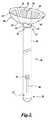
図1は、HIFU療法トランスデューサ2を備えるプローブ1を例示し、このHIFU療法トランスデューサ2は、女性患者3の膣腔に導入されている。この特定の実装において、HIFU療法トランスデューサは子宮頸部に結合され、点線によって示されるHIFUエネルギーの高密度焦点式ビームを、子宮内の治療部位に送達するように設計される。この例示において、治療部位は、子宮フィブロイド4である。図11および図12に関して後で本明細書において記述されるように、治療部位は、子宮腔の子宮内膜組織および/または子宮頸部のCINもしくはHPV関連の病変を含み得る。HIFU療法トランスデューサ2は、一定の子宮組織溶剤を通して超音波放出を方向付けることができ、それによって超音波エネルギーの治療効果、および可能性として、診断上の効果を高める。 FIG. 1 illustrates a probe 1 comprising a HIFU therapy transducer 2 that has been introduced into the vaginal cavity of a female patient 3. In this particular implementation, a HIFU therapy transducer is coupled to the cervix and is designed to deliver a dense focused beam of HIFU energy, indicated by the dotted line, to a treatment site in the uterus. In this illustration, the treatment site is uterine fibroid 4. As described later herein with respect to FIGS. 11 and 12, the treatment site may include endometrial tissue in the uterine cavity and / or CIN or HPV related lesions in the cervix. The HIFU therapy transducer 2 can direct ultrasound emission through certain uterine tissue solvents, thereby enhancing the therapeutic effect of ultrasound energy and possibly the diagnostic effect.
さらなる結合デバイスが、トランスデューサ2と子宮頸部との間で使用され得、超音波放出を最適化し得る。結合は、冷却構成要素も含み得る。流体で満たされた様々なピロー(pillow)が当技術分野で公知であり、これら様々なピローは、HIFUトランスデューサとある量の組織との間に冷却された結合を提供し得る。図1に示されたプローブ1は、外部の源への結合5をさらに含み、外部の源は、循環する冷却流体およびプローブの構成要素を動作させるための、プローブ1へのエネルギーを送達し得る。冷却流体は、HIFUトランスデューサ、および子宮頸部を含むがこれに限定されないトランスデューサを取り囲む組織の温度を下げ、焦点式HIFUビームからの熱による付随的な損傷のリスクを少なくするために使用される。トランスデューサ2を子宮頸部に結合することは、臨床医が、子宮頸部および子宮の位置を操作して、HIFU治療を最適化することをさらに可能にする。 Additional coupling devices can be used between the transducer 2 and the cervix to optimize ultrasound emission. The coupling may also include a cooling component. Various pillows filled with fluid are known in the art, and these various pillows may provide a cooled bond between the HIFU transducer and an amount of tissue. The probe 1 shown in FIG. 1 further includes a coupling 5 to an external source, which can deliver energy to the probe 1 for operating the circulating cooling fluid and probe components. . The cooling fluid is used to lower the temperature of the tissue surrounding the HIFU transducer and the transducer, including but not limited to the cervix, and to reduce the risk of collateral damage due to heat from the focused HIFU beam. Coupling the transducer 2 to the cervix further allows the clinician to manipulate the position of the cervix and uterus to optimize HIFU treatment.
本明細書に論じられるHIFU療法トランスデューサは、膣腔への挿入を容易にする小型の状態を有し、挿入の後、HIFU療法トランスデューサは、より大きな状態に広げられ、この状態でトランスデューサは、身体の標的組織へHIFU療法を送達する。 The HIFU therapy transducers discussed herein have a compact state that facilitates insertion into the vaginal cavity, and after insertion, the HIFU therapy transducer is expanded to a larger state, where the transducer is HIFU therapy is delivered to the target tissue.
必要ならば、プローブ1は、様々な骨盤器官および病状を視覚化するように動作可能である画像化構成要素をさらに含み得る。画像化構成要素は、関心のある組織および/または組織の血流の二次元または三次元のビジュアル画像を生み出すように、かつ見えている組織の温度の定量化を提供するように設計され得る。さらに、画像化システムは、超音波エネルギーを使用するように設計されているが、画像化技術は、そのようなエネルギーモダリティに限定されない。 If necessary, the probe 1 can further include an imaging component operable to visualize various pelvic organs and pathologies. The imaging component can be designed to produce a two-dimensional or three-dimensional visual image of the tissue of interest and / or blood flow of the tissue and provide quantification of the temperature of the visible tissue. Furthermore, although imaging systems are designed to use ultrasonic energy, imaging techniques are not limited to such energy modalities.
図示されるように、HIFUトランスデューサの療法構成要素は、様々な構成で構成され得、最適の焦点距離ならびにアパーチャの大きさおよび形状を達成し、治療目的に対する最適のエネルギー送達を達成する。本明細書に記述されるように、本発明の実装は、例えば子宮のフィブロイド腫瘍ならびに子宮内膜組織および子宮頸部組織などの意図された標的への最適のエネルギー送達を提供し、一方、近くの組織への付随的な損傷を限定するようにも構成され得る。トランスデューサの励起の高調波ならびにエネルギー放出の位相および方向を管理することによって、HIFU伝送の焦点の形状および位置は、調節され得る。本発明の実装に対する適切なHIFUトランスデューサの選択は、HIFU技術における当業者の知識の範囲内に充分にある。 As shown, the therapy component of the HIFU transducer can be configured in a variety of configurations to achieve optimal focal length and aperture size and shape to achieve optimal energy delivery for therapeutic purposes. As described herein, implementations of the present invention provide optimal energy delivery to intended targets such as fibroid tumors of the uterus and endometrial and cervical tissue, while nearby It may also be configured to limit incidental damage to the tissue. By managing the harmonics of the excitation of the transducer and the phase and direction of the energy emission, the shape and position of the focus of the HIFU transmission can be adjusted. The selection of an appropriate HIFU transducer for implementation of the present invention is well within the knowledge of those skilled in the art of HIFU technology.
HIFUエネルギーを生成するための素子は、当技術分野において充分に周知である。HIFUトランスデューサは、例えば、焦点範囲の制御を可能にし得る環状のアレイで配列されたHIFU生成素子で構成され得る。あるいは、HIFU生成素子は、直線状のアレイで配列され得、直線状のアレイは、焦点範囲の制御と操縦の制御の両方を可能にし得る。さらに他の実装において、素子は、二次元のアレイで配列され得、二次元のアレイは、三次元での焦点範囲の制御および操縦の制御を可能にし得る。後者の配列は好ましくは、三次元の超音波視覚化を可能にする二次元の画像化アレイと連携して使用される。複数の素子が使用される場合、素子は、位相を変えて調節され得、身体の様々な標的に対して、HIFUトランスデューサの焦点を正しくあわせることを可能にし得る。あるいは、複数の素子からのHIFU放出は調整されて、あたかも単一の素子から来るかのようなビームを生み出す。本明細書に開示されたようなHIFU療法を提供するように適合され得るHIFUトランスデューサの例は、例えば、「Image Guided High Intensity Focused Utrasound Device for Therapy in Obstetrics and Gynecology」と題し、その開示は本明細書に参考として援用された米国特許出願公開第2005/0203399号において、Shahram Vaezyらによって開示されている。 Elements for generating HIFU energy are well known in the art. The HIFU transducer can be composed of, for example, HIFU generating elements arranged in an annular array that can allow control of the focal range. Alternatively, the HIFU generating elements may be arranged in a linear array, which may allow both focal range control and steering control. In yet other implementations, the elements can be arranged in a two-dimensional array, which can allow for focus range control and steering control in three dimensions. The latter arrangement is preferably used in conjunction with a two-dimensional imaging array that allows three-dimensional ultrasound visualization. If multiple elements are used, the elements can be adjusted out of phase to allow the HIFU transducer to be correctly focused on various targets in the body. Alternatively, HIFU emissions from multiple elements are adjusted to produce a beam as if it came from a single element. Examples of HIFU transducers that may be adapted to provide HIFU therapy as disclosed herein include, for example, “Image Guided High Intensity Focused Devices for Therapeutics in Obstetrics and the G U.S. Patent Application Publication No. 2005/0203399, incorporated herein by reference, as disclosed by Shahram Vaezy et al.
図1に示されるようなHIFU療法を送達するための装置は、図2により詳細に示される。装置は、近位端12および遠位端14を有する細長いプローブ10を含む。プローブ10が、孔を通して患者の身体に挿入されるとき、プローブ10の近位端12は好ましくは、体腔内の所望の位置に遠位端14を位置決めするために適合された区間を有する。この実装において、プローブ10の遠位端14は、それに結合されたHIFU療法トランスデューサ16を有する。HIFU療法トランスデューサ16は、複数のリーフ18を含む。示されるように各リーフ18は、近位端20および遠位端22、ならびに以下により詳細に論じられる展開メカニズムを有する。各リーフ18の近位端20は、プローブ10の遠位端14に結合される。 A device for delivering HIFU therapy as shown in FIG. 1 is shown in more detail in FIG. The apparatus includes an
各リーフ18は、HIFU療法トランスデューサ16が展開するとき、患者の身体の治療部位にHIFUエネルギーを方向付けるように適合されたフロント表面24を有する。図2に示される実装において、リーフのうちの少なくとも1つのリーフのフロント表面24は、その上に配置された能動素子26を含む。能動素子26は、例えば図1に示されるフィブロイドなどの治療部位にトランスデューサ16によって方向付けられるHIFUエネルギーを生成するように動作可能である。HIFUエネルギーを生成するために能動素子を動作させるために必要なHIFU生成素子ならびに信号およびシステムは、当技術分野において周知であり、本明細書において論じられる必要はない。例えば、圧電技術を使用するHIFU素子は、当技術分野において公知であり、本明細書で論じられる実装において使用され得る。 Each
HIFU療法トランスデューサ16のリーフ18を構成するために使用される材料およびリーフ18の寸法によっては、リーフ18は各々、互いから分離して、独立的にプローブ10に結合され得る。トランスデューサ16の安定性のために、リーフ18は、必要であれば、相互に接続されることもあり得る。図2においては、リーフ18は、スライドして互いに重なり合うことによって、より小さな状態に折りたたまれるように構成され、このようにして、図2に示されるような展開した状態から、体腔へのプローブ10の挿入を容易にするより小型の状態に、HIFU療法トランスデューサ16の寸法を低減する。 Depending on the materials used to construct the
リーフ18の各々は、プローブ10が患者に挿入された後、図2に示されるような状態に、HIFU療法トランスデューサ16を展開するために使用される展開メカニズムを有する。展開メカニズムは、作動するとき、半径方向外向きにリーフ18の遠位端22を方向付けることによってリーフ18を展開するように構成される。このようにしてリーフは展開し、プローブ10の直径よりも大きい直径を有する外側エッジ28を有する、碗状のHIFU療法トランスデューサ16を全体として提供する。HIFU療法トランスデューサ16は、展開したとき、患者の治療部位にHIFUエネルギーの高密度焦点式ビームを方向付けるために十分なサイズのアパーチャを有する。展開メカニズムが作動しないとき、折りたたまれたリーフ18は、リーフ18が展開したときのトランスデューサ16の外側エッジ28の直径よりも小さな直径を有するスペースを占める。 Each of the
図2に示された実装、および本明細書に開示された特定の他の実装において、プローブ10は、シャフト32の周りに配置されたスリーブ30を含む。スリーブ30は、近位端34、遠位端36、およびその間に延びる長手方向の軸を有する。シャフト32は、プローブ10の長手方向の軸に沿って、引込められた位置から延長された位置へスリーブ30内をスライドするように構成される。 In the implementation shown in FIG. 2 and certain other implementations disclosed herein, the
引込められた位置から延長された位置へシャフトがスライドすることを補佐するために、例えばボタン38のようなアクチュエータが提供され得る。図2において、ボタン38は、シャフト32に接続され、スリーブ30の溝40内をスライドする。プローブを操作する臨床医は、ボタン38を把持し、ボタン38を図2に示される位置へ溝40内でスライドさせ、シャフトを延長された位置に置き得る。 An actuator, such as a
ボタン38が、溝40の中をプローブの近位端34に向かってスライドするとき、シャフト32は、スリーブ30の中に引き込まれる。シャフト32が、内側に向かってスライドするとき、リーフ18は、スリーブ30の遠位端36と接触し、内側に向かって収縮し、スリーブ30の中に引き込まれる。図示の実施形態において、シャフト32がスリーブ30内に引き込まれ、リーフ18が収縮するとき、各リーフ18の一部分は、隣接するリーフ18の前でスライドするように設計される。 As the
図2は、プローブ10の遠位端14におけるヒンジ42をさらに例示する。この実装において、HIFU療法トランスデューサ16は、ヒンジ42を介して、プローブ10の遠位端14に結合される。ヒンジ42は軸を有し、トランスデューサ16は、その軸回りに回転し得、例えば図1に示されるように、患者の身体の治療部位に向かってHIFUエネルギーのねらいを定め得る。 FIG. 2 further illustrates a hinge 42 at the distal end 14 of the
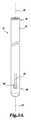
図1および図2に示されるプローブ10と同様に、図3A〜図3Cは、引込み可能なリーフ54から構成されるHIFU療法トランスデューサ52を有する細長いプローブ50の実装を例示する。プローブ50は、スリーブ内のシャフト70(図4)の周りに配置されたスリーブ56を含む。スリーブ56は、近位端58、遠位端60、およびその間に延びる長手方向の軸62を有する。シャフトは、長手方向の軸62に沿って、図3Aに示されるような引込められた位置から、図3Cに示されるような延長された位置へスリーブ56の内側をスライドするように構成される。図3Bは、引込められた位置と延長された位置との間の中間段階におけるシャフトを例示する。 Similar to the
図1および図2に示される実装と同様に、各リーフ54は、プローブ50が患者の身体に挿入されているとき、治療部位にHIFUエネルギーを方向付けるように適合された正面64を有している。フロント表面64に配置された能動素子66は、治療部位に方向付けられるHIFUエネルギーを生成するように動作可能である。図3A〜図3Cにおける実装は、能動素子66を備えているフロント表面64を有する複数のリーフ54を示すが、リーフ54のうちのすべてが能動素子を有する必要はない。実際、少なくとも一部の実装においては、フロント表面64は、HIFUエネルギーを生成するための能動素子を備えないように設計し得る。その代わりに、リーフ54のうちの少なくとも1つのフロント表面64は、治療部位の方に向けてHIFUエネルギーを反射させるように構成され、その治療部位において、HIFUエネルギーは、リーフから遠い源から受取られる。例えば、HIFUエネルギー源は、HIFU療法トランスデューサ52に対しては中央であるが、リーフ54からは離れている位置においてプローブと結合され得る。あるいは、HIFUエネルギー源は、プローブ50とは別個に位置し得る。いずれの場合においても、リーフ54のうちの少なくとも1つのフロント表面64には、表面64に入射するHIFUエネルギーを反射するミラー状の材料が提供される。入射エネルギーを反射することで知られている特性を有する材料は、容易に入手可能であり、当業者によって認識される。リーフ54の幾何学的形状は、展開した状態で、患者の意図された治療部位における焦点にHIFUエネルギーを方向付けるように構成される。 Similar to the implementation shown in FIGS. 1 and 2, each leaf 54 has a front face 64 adapted to direct HIFU energy to the treatment site when the probe 50 is inserted into the patient's body. Yes. An active element 66 disposed on the front surface 64 is operable to generate HIFU energy that is directed to the treatment site. The implementation in FIGS. 3A-3C shows a plurality of leaves 54 having a front surface 64 with active elements 66, but not all of the leaves 54 need to have active elements. Indeed, in at least some implementations, the front surface 64 may be designed to include no active elements for generating HIFU energy. Instead, the front surface 64 of at least one of the leaves 54 is configured to reflect HIFU energy toward the treatment site, where the HIFU energy is received from a source remote from the leaf. . For example, the HIFU energy source may be coupled to the probe at a location that is central to the HIFU therapy transducer 52 but remote from the leaf 54. Alternatively, the HIFU energy source may be located separately from the probe 50. In either case, the front surface 64 of at least one of the leaves 54 is provided with a mirror-like material that reflects HIFU energy incident on the surface 64. Materials having properties known to reflect incident energy are readily available and will be recognized by those skilled in the art. The leaf 54 geometry is configured to direct HIFU energy to a focal point at the intended treatment site of the patient in the deployed state.
図4は、図3Bに示されるプローブ50の側面断面図を例示する。図4において、スリーブ56は、シャフト70の周りに配置された状態で示される。リーフ54の各々は、近位端72および遠位端74を有する。各リーフ54の近位端72は、例えばピン、接着剤、溶接などにより、シャフト70の遠位端76に結合される。リーフ54が、能動HIFU生成素子を含む場合、結合は、例えばワイヤなど、プローブ50から能動素子にエネルギーを伝達する手段をさらに含む。 FIG. 4 illustrates a side cross-sectional view of the probe 50 shown in FIG. 3B. In FIG. 4, the
各リーフ54は展開メカニズムを含み、この展開メカニズムは、作動するとき、半径方向外向きにリーフの遠位端72を方向付けることによって、リーフ54を展開させる。図3A〜図3Cおよび図4に示される実装において、各リーフの展開メカニズムは、スリーブ56の遠位端60に結合されるピン78を含む。ピン78は、リーフ54に画定された溝80(図3Bおよび図3C)内をスライドするように構成される。 Each leaf 54 includes a deployment mechanism that, when activated, deploys the leaf 54 by directing the distal end 72 of the leaf radially outward. In the implementation shown in FIGS. 3A-3C and 4, the deployment mechanism of each leaf includes a
この実装における展開メカニズムの作動は、図3Cに示される延長された位置に向かって、スリーブ56内でシャフト70をスライドさせることを含む。シャフト70が、スリーブ56の中を上に向かってスライドするとき、各リーフ54は、スリーブ56の遠位端60から外向きに押される。図3Cに示されるように、各リーフは外向きに押されるとき、各それぞれのリーフ54に対するピン78は、溝80の中をスライドし、リーフの遠位端74を半径方向外向きの所望の位置に方向付け、その位置において、リーフは全体として、碗状のHIFUトランスデューサ52を提供する。 Activation of the deployment mechanism in this implementation involves sliding the
例示された実装において、シャフト70が延長された位置にスライドするとき、リーフ54は、横向き、かつ外向きに方向付けられるように、溝80は、長手方向の軸62に対してある角度で画定される。同様に、シャフト70が、図3Aに示される引込められた位置に引かれるとき、各リーフ54に対するピン78は溝80内をスライドし、リーフが、スリーブ56に引き込まれるにつれて、リーフを横方向、かつ半径方向内向きに案内する。図3Bに示されるように、リーフが、スリーブ56内に引込められて保持されるとき、複数のリーフにおけるリーフ54の少なくとも一部分は、別のリーフ54の少なくとも一部分と重なるように構成される。図3A〜図3Cに示されるように、シャフト70を引込める、または延長することを補佐するために、例えばボタン82のようなアクチュエータがシャフト70に取り付けられ得る。図1および図2に示される実装と同様に、ボタン82は、スリーブ56に画定された溝84内をスライドし得る。スリーブ56の遠位端60の方に向かうか、またはこれから離れる方向にボタン82に対して及ぼされる力は、シャフト70をスリーブ内で動かすためにシャフト70に伝えられる。 In the illustrated implementation, the
必要ならば、ピン78は、各それぞれのリーフの溝80内にピンを固定するように構成された戻り止を含み得る。さらに、必要ならば、シャフトが延長された位置にあり、従ってシャフト70の遠位端76を、スリーブ56の外に露出させる場合に、プローブ50は、シャフト70の遠位端76が、スリーブ56の遠位端60を越えて延びるように構成され得る。この後者の特徴は、プローブ50が、シャフト70の遠位端76における画像化構成要素86と共に構成されるとき、有利であり得る。画像化構成要素86をシャフトの遠位端、またはプローブの遠位端に結合することは、患者にHIFU療法を送達する過程を補佐する。 If desired, the
画像化構成要素86は好ましくは、HIFUエネルギーを受取る治療部位を含む患者の身体の一部分の画像を生み出すように適合される。従来の画像化技術が使用され得る。画像は、治療部位へのHIFUエネルギーの送達を案内することに役立つ。一局面において、画像化構成要素は、反射された超音波エネルギーを使用して、患者の身体の該一部分の画像を生み出すように構成され得る。診断用の超音波は、組織に損傷を与えないように、はるかにより低い出力密度で超音波エネルギーを使用する。 The
あるいは、画像化構成要素86は、反射された光を使用して、患者の身体の一部分のビジュアル画像を生み出すように構成され得る。光ベースの画像化技術は、例えば、光の光ファイバー伝送および受光、レンズ(必要に応じて)、および/または画像を生み出すために反射光を受光し、測定し得る電荷結合素子(CCD)などの素子を含み得る。反射された超音波エネルギーが好まれる。なぜならば、患者の身体における様々な深さでの組織の形および密度が、観察され得るからである。 Alternatively, the
反射された超音波エネルギーが、画像を生み出すために使用される場合、診断用の超音波エネルギーの放出および受け取りは、画像化構成要素86によって取得された画像をぼかさないために、HIFUエネルギーの伝送と同期させられるべきである。画像化およびHIFUパルスを同期させるための技術は、当技術分野において利用可能である。例えば、Shahram Vaezyらによる、「Interference−Free Ultrasound Imaging During HIFU Therapy,Using Software Tools」と題し、その開示が本明細書に参考として援用された米国特許出願公開第2006/0264748号を参照されたい。 When the reflected ultrasound energy is used to produce an image, the emission and reception of diagnostic ultrasound energy does not blur the image acquired by the
さらに、画像化技術は、HIFUトランスデューサまたは画像化構成要素のいずれかから取得された超音波後方散乱情報を使用して、標的部位の二次元または三次元のリアルタイムの観察、ならびに標的組織の血流カラー画像化(Doppler)および温度変化の数量化を提供するために使用され得る。 In addition, imaging techniques use ultrasound backscatter information obtained from either HIFU transducers or imaging components to provide two-dimensional or three-dimensional real-time observation of the target site, as well as blood flow of the target tissue. It can be used to provide color imaging (Doppler) and quantification of temperature changes.
図5Aおよび図5Bは、展開され、全体として、碗状のHIFUトランスデューサ104を提供し得る複数のリーフ102を含んで、図1〜図4に関して示され、記述された特徴と同様な特徴を備えるプローブ100の実装を例示する。既に記述された実装と同じく、プローブ100は、スリーブ内でシャフトの周りに配置されたスリーブ106をさらに含む。例えばボタン108のようなアクチュエータが、シャフトに接続され、図5Aに示されるような引込められた位置から、図5Bに示されるような延長された位置へ、シャフトをスライドさせることを補佐する。 5A and 5B include features similar to those shown and described with respect to FIGS. 1-4, including a plurality of
既に記述された実装とは対照的に、リーフ102は、スリーブ106に結合される。さらに詳細には、各リーフ102は、近位端110および遠位端112を有する。各リーフの近位端110は、スリーブ106の遠位端114に結合される。さらに、スリーブ104の近位端116は、プローブ100が患者に挿入されたとき、患者の身体内の所望の位置に、遠位端114を位置決めするように適合された区間を有し得る。 In contrast to the previously described implementation,
図5Aにおいて点線でさらに示されるように、複数のスパイン118は、スリーブ106内で、シャフトの遠位端120に結合され得る。図5Aに示されるように、シャフトが引込められた位置にあるとき、スパイン118は、スリーブ106内に保持される。リーフ102は、図示されるように、折りたたまれた構成で互いに重なり合い得るように構成され、この場合、リーフ102は、共にまとめられてより狭い空間を占めることができる。例えば、図5Aに示されるように、リーフ102の群は、スリーブ106の直径に等しいか、またはこれよりも小さい直径を有する空間を占め得る。折りたたまれた状態のリーフを有することは、プローブ100を患者の身体に挿入することを容易にする。プローブ100が、患者の身体の意図された空洞に挿入された後、リーフ102が展開され得るが、この際、展開メカニズム、すなわち、スパイン118を使用して、各リーフの遠位端112を、半径方向外向きの所望に位置に方向付け、碗状のHIFUトランスデューサ104を提供する。 As further indicated by the dotted lines in FIG. 5A, a plurality of
従って、動作において、図5Aおよび図5Bに対する展開メカニズムの作動は、図5Bに示されるように、延長された位置に向かってスリーブ106内でシャフトをスライドさせることを含む。シャフトが、スリーブ内でスライドするとき、スパイン118が、スリーブ106から現れ、リーフ102の各々に画定された溝122内をスライドする。スパイン118が、漸進的に溝122に入るとき、スパイン118は、各リーフ102の遠位端を、半径方向外向きに方向付ける。スパイン118は、複数のリーフが展開されるとき、リーフ102に支持を提供もする。シャフトを引込められた位置に向かってスリーブ106の中に引込めることは、溝122からスパイン118を取り下げることになり、これによって、リーフ102は、図5Aに示された状態に折りたたむことができる。 Accordingly, in operation, actuation of the deployment mechanism with respect to FIGS. 5A and 5B includes sliding the shaft within the
スパイン118は、シャフトが、延長され、リーフが展開されたとき、リーフ102に支持を提供することができる適切な材料で構成され得る。シャフトが延長され、スパイン118が溝122を満たすとき、スパイン118は、リーフ102に対して外向きの付勢力を及ぼすように構成され得る。図5Bに示されるように、スパイン118は、リーフ104を展開された状態に保持するように構成される。必要ならば、1つ以上のストップが、スリーブ106の遠位端114に画定され得、一旦リーフが展開された位置に達すると、リーフ102と係合し得る。スパイン118の外向きの付勢力は、スパインを構成するために使用される材料の自然な特徴から生じ得、そのようなスパインの例としては、スリーブ106の外側で着座した状態で外向に湾曲した材料で形成されるスパインがあり、この材料は柔軟であり、スリーブ106の内側で真っ直ぐな着座していない状態に曲がる。あるいは、例えばばねのようなメカニズムが、スパイン118に対して構成され得、スパイン118を圧し、展開されたとき、半径方向外向きにリーフを方向付ける。
別の代替の実装においては、第1の端がシャフトに結合され、第2の端がリーフ内に配置されたばねから成る展開メカニズムが使用され得る。図3A〜図3Cの図面を使用して、展開のためにばねを使用する実装が視覚化され得、この場合、溝80は、スリーブ56のピン78によって案内される代わりに、記述されたように、ばねの第2の端で満たされる。この場合、ばねの第2の端は、溝80が示されるようなある角度で配置される必要はない。図3Cに示されるように、スリーブ56内のシャフトが、延長された位置へ上向きにスライドさせられるとき、ばねの第2の端は、スリーブ56から現れ、外向きの付勢を及ぼし、半径方向外向きにリーフ54の遠位端を方向付ける。同様に、図3Aに示されるように、シャフトをスリーブ56内に引込めることは、リーフ54をばねと共にスリーブ56の中に引込めることになり、そこでリーフとばねは保持される。 In another alternative implementation, a deployment mechanism consisting of a spring with a first end coupled to the shaft and a second end disposed within the leaf may be used. Using the drawings of FIGS. 3A-3C, an implementation using a spring for deployment can be visualized, where the
さらに別の実装において、例えば図5Bに示されるリーフ102のようなリーフの一部分は、エネルギー作動型形状記憶合金で形成され得る。この実装におけるリーフ102の展開メカニズムは、形状記憶合金をエネルギー源に接続する結合を含む。展開メカニズムの作動は、エネルギー源から各リーフの形状記憶合金へエネルギーを送達することを含み、このエネルギーは、形状記憶合金に所定の形状を取らせ、リーフ102の遠位端は、半径方向外向きに方向付けられ、碗状のHIFUトランスデューサ104を提供する。 In yet another implementation, a portion of a leaf, such as
通常の形状記憶合金は、ニッケルおよびチタンで作られ、その柔軟性および形状を変化させる特性で知られている。合金は、特定の温度でその内部構造を動的に変化させる。例えばリーフ102のような形状記憶合金で形成された構造は、室温で変形させられ得、形状記憶合金が加熱されるとき、合金は、構造を所定の形状に推移させる。例えば、形状記憶合金は、加熱されたとき収縮し得、元の温度に戻るとき再び容易に伸展し得る。形状記憶合金のエネルギー駆動加熱および冷却は、かなり速やかに達成され得る。 Conventional shape memory alloys are made of nickel and titanium and are known for their flexibility and shape changing properties. An alloy dynamically changes its internal structure at a specific temperature. For example, a structure formed of a shape memory alloy, such as
本発明の状況下では、例えば、図5Bに示されるプローブ100(図5Aに示されるスパイン118を備えていない)は、プローブに結合された近位端110を有する複数のリーフ102を含み得る。各リーフ102の一部またはすべては、形状記憶合金で形成され得る。プローブ内のエネルギー源からのエネルギーが、リーフの形状記憶合金に送達されるとき、リーフは、半径方向外向きに曲がり、図示のようなHIFU療法トランスデューサ104を提供する。スパイン118が使用されるような実装において、スパインは、形状記憶合金で形成され得、形状記憶合金は、合金へエネルギーが適用されることによって作動させられ、スパイン118の各々が、半径方向外向きに曲がるようにし、このようにして、リーフ102を展開された状態に置く。そのような実装において、スパイン118は、図5Aに示されるように、溝122内に引込むか、または引込まないことがあり得る。スパイン118が引込まない場合にも、スパイン118の形状記憶合金が、エネルギー源によって作動させられていない場合には、リーフ102は、なおも折りたたまれて群になることができる。 In the context of the present invention, for example, the
図6Aおよび図6Bをここで参照して、別の実装は、近位端132、遠位端134、およびその間に延びる長手方向の軸136を有する細長いプローブ130を含む。本明細書における他の実装と同じように、プローブ130の近位端132は、プローブ130が患者に挿入されるとき、患者の身体内の所望の位置にプローブの遠位端134を位置決めするように適合された区間を有する。 Referring now to FIGS. 6A and 6B, another implementation includes an
プローブ130の遠位端134は、HIFU療法トランスデューサ140をプローブ130に結合する柔軟な材料138と継がれる。HIFU療法トランスデューサ140は、患者の治療部位に治療用HIFUエネルギーを方向付けるために十分な大きさのアパーチャを有する。参照の目的で、HIFU療法トランスデューサ140は、その面を横断する主軸142を有する。 The
着座の状態においては、図6Bに示されるように、柔軟な材料138は、トランスデューサ140を治療位置にあるプローブ130に結合し、この治療位置においては、トランスデューサの主軸142は、プローブの長手方向の軸136に対して非平行である。例えば、膣口を通して、患者の身体にプローブ130を挿入することを容易にするために、柔軟な材料138が伸びて、トランスデューサ140が、図6Aに示されるように、プローブ130の側の挿入位置へと引かれることを可能にするように構成される。挿入位置において、トランスデューサ140の主軸142は、プローブ130の長手方向の軸136と概ね平行である。これは、トランスデューサ140の最大の寸法が、膣口の矢状軸方向にあることを可能にする。柔軟な材料138(つまり、伸びた材料)は、図6Bに示されるようなその着座状態に向かって戻る付勢を発揮する。プローブ130が、例えば膣腔など、患者の身体の意図された空洞に挿入された後、トランスデューサ140は、挿入位置から解放され、図6Bに示される療法位置に戻ることが可能となる。 In the seated state, the
必要ならば、アクチュエータが、HIFU療法トランスデューサ140と結合され得、プローブが、患者に挿入されるか、または患者から引き抜かれる間に、プローブ130の側にトランスデューサ140を引き得る。アクチュエータは、図6Bに示される療法位置にトランスデューサ140を展開させるためにも操作され得る。適切なアクチュエータは、図6Aに示されるような挿入位置に、または図6Bに示されるような療法位置にトランスデューサを引き、押し、かつ/または保持し得るケーブルおよび/またはラッチを含むが、これらに限定されない。少なくとも1つの実装において、トランスデューサ140を展開させるためにアクチュエータを操作することは、単に、トランスデューサを解放し、柔軟な材料138がトランスデューサを療法位置に配置することを可能にすることを含み得る。別の実装において、アクチュエータは、トランスデューサ140を所望の療法位置に能動的に動かし得る。 If necessary, an actuator can be coupled to the
既に記述された他の実装と同様に、プローブ130の遠位端134は、プローブ130が患者に挿入されたとき、患者の身体の一部分の画像を生み出すように適合された画像化構成要素144を含み得る。好ましくは、画像化構成要素によって生み出された画像は、トランスデューサ140からHIFUエネルギーを受取る治療部位を含み、HIFUエネルギーの治療部位への送達を案内することを助ける。一実装において、画像化構成要素は、反射された超音波エネルギーを使用して、患者の身体の一部分の画像を生み出すように構成され得る。代替の実装において、画像化構成要素は、反射光を使用して画像を生み出すように構成され得る。いずれの場合においても、画像化構成要素によって生み出された画像は、HIFU療法トランスデューサ140の一部分をさらに含み得、患者の身体内にトランスデューサ140を位置づけて治療部位で生じるHIFU療法を監視することを補佐し得る。 As with the other implementations already described, the
適切な実装において、柔軟な材料138は、例えば医療用プラスチック、ゴム、またはシリコンなどの弾力性の非金属材料で構成され得る。代替の実装において、柔軟な材料138は、合金のエネルギー作動次第で、伸展された状態、または着座状態を有する形状記憶合金で構成され得る。形状記憶合金は、合金に供給されるエネルギーに基づいて予め画定された形状をとるように作動させられ得、供給されるエネルギーは、通常合金を加熱して形状を変化させる。形状記憶合金の構造および使用に関する詳細は、本明細書において既に論じられた。 In a suitable implementation, the
さらに、既に記述された実装と同じように、能動素子146が、HIFU療法トランスデューサ140に配置され得、この場合、能動構成要素は、トランスデューサ140が治療部位に方向付けるHIFUエネルギーを生成するように動作可能である。あるいは、HIFU療法トランスデューサ140は、治療部位に向かってHIFUエネルギーを反射させる表面と共に構成され得る。この後者の実装におけるHIFUエネルギーは、トランスデューサ140から遠く離れた源から受取られ得る。例えば反射マイラーなどの材料は、それに入射する超音波エネルギーを反射することができ、当技術分野で公知である。 Further, similar to the implementation described previously, an
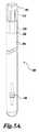
本発明に従って構成される装置のさらに別の実装において、図7Aおよび図7Bに示されるようなプローブ160は、患者の身体の病状を治療するために使用され得る。患者にプローブ160を挿入することを容易にするために、プローブ160は、1つ以上の膨張式ブラダーで形成されたHIFU療法トランスデューサと共に構成される。 In yet another implementation of an apparatus constructed in accordance with the present invention, a
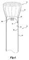
前の実装と同じように、細長いプローブ160は、近位端164および遠位端166を有する。近位端164は好ましくは、プローブ160が患者の身体に挿入されるとき、所望の位置にプローブの遠位端166を位置決めするように適合された区間を有する。プローブ160の遠位端166は、1つ以上の膨張式ブラダーを有する柔軟な材料と継がれ、1つ以上の膨張式ブラダーは、膨張されたとき、HIFU療法トランスデューサ162を提供する。トランスデューサ162は、患者の治療部位へ治療用のHIFUエネルギーの集中されたビームを方向付けるために十分な大きさのアパーチャを有する。膨張式ブラダーは、例えばゴムまたはシリコンなど(しかしこれらに限定されず)、拡張可能な材料で構成され得る。 Similar to the previous implementation, the
1つ以上の膨張式ブラダー168は、プローブ160の遠位端166から半径方向外向きに延びる。ブラダー168は、例えば膣口を通して膣腔など、患者の身体の意図された空洞にプローブが挿入されるあとまでは、膨張させられない。挿入のあと、ブラダー168は、膨張させられ、HIFU療法トランスデューサ162を形成し、患者の身体内で、HIFU療法トランスデューサ162に横方向の支持を提供する。膨張させられたとき、トランスデューサ162は、プローブ160の直径よりも大きいアパーチャを有する。膨張式ブラダー168に、例えば液体または気体など加圧された流体を送達するための適切な導管が、プローブ160内に提供され、ブラダー168に結合される。同様に、ブラダーがしぼむとき、ブラダー168から流体を導き出すために、導管が提供される。必要ならば、HIFU療法が適用されるとき、流体(液体または気体)が、ブラダー168を往復して循環させられて冷却され得、トランスデューサ162および/またはトランスデューサ162の近くの組織の温度を管理することを助ける。 One or more
図7Bにさらに示されるように、HIFU療法トランスデューサ162を形成する柔軟な材料は、プローブ160が挿入され、ブラダー168が膨張されたとき、HIFUエネルギーを患者の治療部位に方向付けるように適合されるフロント表面170を有する。 As further shown in FIG. 7B, the flexible material forming the
図7Aおよび図7Bに例示された実装において、ブラダー168は、プローブ160の遠位端166から半径方向外向きに延びる1つ以上の膨張式チャンネルを含む。柔軟な材料のフロント表面170は、膨張式のチャンネル168の間に延びる。 In the implementation illustrated in FIGS. 7A and 7B, the
必要ならば、膨張式チャンネル168は、HIFU療法トランスデューサ162の外側エッジ174を形成する膨張式リング172で終端し得る。リング170は、膨張させられたとき、HIFU療法トランスデューサ162にさらなる支持を提供し、患者へHIFU療法を送達するためのトランスデューサのアパーチャを維持する。膨張させられたとき、リングの断面で測定されるリング172の直径は、プローブの遠位端166において測定されるプローブ160の直径よりも大きい。 If desired, the
図7Bにおいて、柔軟な材料のフロント表面170は、1つ以上の能動素子176と共に示され、1つ以上の能動素子176は、トランスデューサ162によって患者の治療部位に方向付けられるHIFUエネルギーを生成するように動作可能である。既に述べられたように、HIFU生成素子は、当技術分野で公知である。能動素子176にエネルギーを提供する導管は、プローブ160内に提供される。あるいは、フロント表面170は、HIFUエネルギーを治療部位に向けて反射させる材料で構成され得る。本明細書に記述された他の実装と同じように、HIFUエネルギーは、柔軟な材料から遠い源から受取られ得る。 In FIG. 7B, a flexible material
さらに、本明細書に記述された他の実装と同じように、プローブ160の遠位端166は、画像化構成要素178をさらに含み得、画像化構成要素178は、治療部位を含む患者の身体の一部分の画像を生み出すように適合される。この態様での患者の画像化は、治療部位へのHIFUエネルギーの送達を案内することを助け得る。既に本明細書で記述されたように、画像化構成要素178は、反射された超音波エネルギーまたは反射光を使用して、画像を生み出すように構成され得る。画像化構成要素178によって生み出された画像は、HIFU療法トランスデューサ162の一部分をさらに含み得、患者の身体内にトランスデューサを位置づけること、および治療部位で送達されるHIFU療法を監視することを補佐し得る。 Further, as with other implementations described herein, the
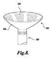
図8は、プローブ180の実装を例示し、プローブ180は同様に、膨張式ブラダーを有する柔軟な材料と継がれ、膨張式ブラダーは、膨張されたとき、HIFU療法トランスデューサ182を提供する。トランスデューサ182は、図示されるように、1つ以上の能動素子184を含み得るか、またはHIFUエネルギーを治療部位に向かって反射させる反射ミラー表面を提供し得る。図7Aおよび図7Bに示される膨張式チャンネル168に対する実装とは対照的に、図8は、単一の膨張式ブラダー186に対する実装を示し、単一の膨張式ブラダー186は、膨張させられたとき、患者にHIFU療法を提供することができる。患者の身体にプローブ180を挿入することを容易にするために、ブラダー186は、プローブが、患者の身体の意図された空洞に挿入されるあとまでは、膨張させられない。ブラダー186は、膨張させられたとき、横方向の支持を形成し、これをHIFU療法トランスデューサ182に提供する。 FIG. 8 illustrates an implementation of the
ここで、図9Aおよび図9Bを参照し、患者の身体内の治療部位へHIFUエネルギーを送達する装置が、本発明の別の実装に従って示される。装置は、近位端202、遠位端204、およびその間に延びる長手方向の軸206を有する細長いプローブ200を含む。プローブ200の近位端202は好ましくは、患者の身体内の所望の位置にプローブの遠位端204を位置決めするように適合される区間を有する。 Referring now to FIGS. 9A and 9B, an apparatus for delivering HIFU energy to a treatment site within a patient's body is shown in accordance with another implementation of the present invention. The device includes an
図9Aおよび図9Bには、画像化構成要素210およびその上に配置されたHIFU療法トランスデューサ212を有する支持構造208が示されている。ヒンジ216は、支持構造208をプローブ200の遠位端204に接続する。 9A and 9B show a
画像化構成要素210は、治療部位を含む患者の身体の一部分の画像を生み出すように適合され、一方、HIFU療法トランスデューサは、治療部位にHIFUエネルギーを送達するように適合されている。HIFU療法トランスデューサは、HIFUエネルギーを治療部位に方向付けるために充分な大きさのアパーチャを有し、画像化構成要素210に対して画定された関係で支持構造208に配置される。示される特定の実装において、HIFU療法トランスデューサ212は、碗状であり、画像化構成要素210は、療法トランスデューサの内部に配置されている。 The
例えば膣口の縦の軸を通して、患者の身体にプローブ200を挿入することを容易にするために、支持構造208は、図9Bに示されるように、プローブ200の長手方向の軸206に対して概ね平行な挿入位置までヒンジ214回りに回転することができる。少なくとも1つの実装においては、その挿入位置であって、プローブの長手方向の軸206に対して垂直に測定された療法トランスデューサ212の寸法は、長手方向の軸206に対して平行に測定されたトランスデューサ212の寸法よりも小さい。ヒンジ214は、画像化および療法トランスデューサ210、212が、ユニットとして患者の身体の治療部位に対して配置されることを可能にする関節運動を提供する。この実装において、画像化とHIFU療法との整列は維持され、従って、画像平面の同じ領域にHIFU療法フィールドの焦点範囲が維持される。有利にも、この領域は、工場において決定、かつ較正され得る。その後、結果として、HIFUトランスデューサのソフトウエア制御は、より簡単となる。 To facilitate the insertion of the
患者の身体にプローブ200の遠位端204を挿入した後、支持構造208は、療法トランスデューサ212から患者の治療部位へのHIFUエネルギーを望まれるように効果的にねらいを定めるように、プローブ200の長手方向の軸206に対して非平行である位置まで、ヒンジ214回りに回転することができる。回転によって、HIFU療法トランスデューサ212は、例えば女性患者の子宮頸部などの身体構造に結合するためにより良い位置に配置されることもできる。 After inserting the
最後に、図10Aおよび図10Bは、図9Aおよび図9Bのプローブ200に示されるものと同様な特徴を有する細長いプローブ220を示す。プローブ220は、近位端222、遠位端224、およびその間に延びる長手方向の軸226を有する。画像化構成要素230およびHIFU療法トランスデューサ232を支える支持構造228は、プローブ220の遠位端224に接続されたヒンジ234回りに回転可能である。 Finally, FIGS. 10A and 10B show an
図9Aおよび図9Bに示されるプローブ200とは対照的に、図10Aおよび図10Bに示される画像化構成要素230は、HIFU療法トランスデューサ232の外側の支持構造228に配置されている。一部の状況においては、療法トランスデューサの外部に画像化トランスデューサを有することは、治療部位の画像化および治療部位に送達されるHIFU療法の効果に対してより有利な角度を提供し得る。 In contrast to the
適切な実装において、画像化構成要素230および画像化構成要素210は、反射された超音波エネルギーを使用して、患者の身体の一部分の画像を生み出すように構成され得る。他の適切な実装において、画像化構成要素230および/または画像化構成要素210は、反射光を使用して、ビジュアル画像を生み出すように構成され得る。反射された超音波エネルギーが画像を生み出すために使用される場合、本発明の実装は、同じトランスデューサ、例えばトランスデューサ212および/または232を使用し得、画像化とHIFU療法の送達の両方を実行し得る。画像化パルスおよびHIFUパルスの適切な同期が望まれる。しかし、そのような場合でも、療法トランスデューサ212、232とは別個の画像化構成要素210、230は、必要ではない。HIFU療法トランスデューサの一部分が、画像に示される場合、画像は、患者の身体内にHIFU療法トランスデューサを位置決めすること、および治療部位におけるHIFU療法の送達を監視することを補佐する。 In a suitable implementation, the
上述のプローブに対する全体的な制御システムは、コンピュータハードウエアおよび/またはソフトウエアを使用して実装され得る。制御システムは、身体の関心のある特定の領域に対する治療方策を臨床医がプログラムするためのツールを提供し得る。ツールは、様々な焦点距離を設定して、組織の二次元または三次元の領域を治療すること、HIFUトランスデューサと焦点との間の組織に関する予想される減衰に基づき、HIFUトランスデューサの励起に対する適切な電力レベルを設定して、焦点(単一素子HIFUまたは複数素子HIFUトランスデューサいずれかに対する)における所望の強さを取得すること、HIFU適用の持続時間を設定すること、それを超えるとシステムが安全の目的のために停止する電力に対する閾値を設定すること、超音波画像取得に関するHIFU露光のデューティサイクルを設定することを含む。インターフェースは、臨床医が、その裁量に基づき、コンピュータ計画を無効にし、治療計画を設計するためのツールも提供する。有利にも、このインターフェースは、治療される必要のある身体の領域を二次元または三次元で画定するためのツールを提供し得、焦点距離の変化(機械的または電子的な)に関する情報を使用して、その領域の治療に対する可能なアプローチを適切に提供し得る。インターフェースは、治療の段階および取るべき次のステップについて臨床医に最新情報を持続的に与え得、かつ計画が進むべきか、または変更されるべきかについて助言し得る。最後に、インターフェースは、組織への望んでいない潜在的な損傷につながる過度のエネルギー堆積を潜在的に生じ得る骨と気体との界面に対する音響経路(前および後焦点)に持続的に問い合わせ得る。 The overall control system for the probes described above can be implemented using computer hardware and / or software. The control system may provide a tool for the clinician to program a treatment strategy for a particular area of interest in the body. The tool sets various focal lengths to treat a 2D or 3D region of tissue, and based on the expected attenuation for the tissue between the HIFU transducer and the focus, Set the power level to get the desired strength at the focus (for either single-element HIFU or multi-element HIFU transducer), set the duration of HIFU application, beyond which the system is safe Including setting a threshold for power to stop for purposes, and setting a duty cycle for HIFU exposure for ultrasound image acquisition. The interface also provides tools for clinicians to override computer plans and design treatment plans based on their discretion. Advantageously, this interface can provide a tool for defining in two or three dimensions the body region that needs to be treated, using information about changes in focal length (mechanical or electronic) Thus, it can adequately provide a possible approach to the treatment of the area. The interface may continuously provide the clinician with up-to-date information about the stage of treatment and the next step to be taken, and may advise whether the plan should proceed or change. Finally, the interface can continually query the acoustic path (front and back focus) to the bone-gas interface that can potentially cause excessive energy deposition that can lead to undesired potential damage to the tissue.
HIFUおよび画像化トランスデューサの動作は、HIFUおよび画像化パルスの正しい同期を可能にする電子的制御システムに基づき得る。HIFU駆動電子機器は、関数発生器から取得される励起信号によって駆動される無線周波数(RF)増幅器に基づき得る。増幅器および関数発生器は、潜在的に一ユニットで実装され得る。HIFU適用の同期は、関数発生器またはRF増幅器段階いずれかでなされ得る。複数素子HIFUトランスデューサの場合に対しては、複数チャンネルHIFUシステムが使用され得る。複数チャンネルシステムの各チャンネルは好ましくは、変化する位相と共に駆動されることができ、身体の様々なスポットでHIFUトランスデューサの焦点を正しく合わせることを可能にする。 The operation of the HIFU and imaging transducer may be based on an electronic control system that allows correct synchronization of the HIFU and imaging pulses. HIFU driving electronics may be based on a radio frequency (RF) amplifier driven by an excitation signal obtained from a function generator. The amplifier and function generator can potentially be implemented in one unit. Synchronization of HIFU application can be done either in the function generator or RF amplifier stage. For the case of a multi-element HIFU transducer, a multi-channel HIFU system can be used. Each channel of the multi-channel system can preferably be driven with varying phases, allowing the HIFU transducer to be correctly focused at various spots on the body.
一部の適用において、HIFUエネルギーは、複数の標的エリアの組織を破壊して、例えば子宮における子宮内膜組織など、ある量の組織を切除するように方向付けられる。標的のエリア内での最大の組織破壊が、必要とされる最小の努力、エネルギー、および時間で達成され得、一方、標的エリアを取り囲む組織に対する潜在的な付随的損傷を最小にもし得る。特に、患者の子宮内膜組織層全体および子宮筋層表面を切除するとき、または子宮頸部の新形成の場合に、患者の病変全体を切除するときは、標的組織内での骨盤器官およびHIFU病変の直接的なリアルタイム視覚化が有用である。これらの適用の例が、以下に記述される。 In some applications, HIFU energy is directed to destroy tissue in multiple target areas and ablate a quantity of tissue, such as endometrial tissue in the uterus. Maximum tissue destruction within the target area can be achieved with the minimum effort, energy, and time required while minimizing potential incidental damage to the tissue surrounding the target area. In particular, when excising the patient's entire endometrial tissue layer and myometrial surface, or in the case of cervical neoplasia, when excising the patient's entire lesion, the pelvic organs and HIFU in the target tissue Direct real-time visualization of the lesion is useful. Examples of these applications are described below.
(子宮内膜の切除)
一例示的な方法は、HIFUエネルギーを使用し、底部の層を貫いて下にある子宮筋層の表面層に入る子宮内膜の全厚を含む子宮内膜表面の一部またはその全部を標的とする。この方法は、子宮内膜の切除を生じる。HIFUエネルギーはまた、治療されるエリアの血管が閉塞され、これによって虚血による子宮内膜の破壊がさらに進む。これは、さらなる子宮内膜組織の再生を防ぎ得る。子宮腺筋腫症の患者において、本明細書に記述された方法は、特に脈管閉塞効果の観点から、子宮腺筋腫症ポケットの閉塞をさらに生じ得、子宮筋層のそれら子宮腺筋腫症ポケットからの子宮内膜組織の再生を防ぎ得る。望ましくは、子宮内膜の切除のための処置は、リアルタイム経膣超音波画像案内HIFU療法を提供する装置を使用して実行され得る。(Resection of endometrium)
One exemplary method uses HIFU energy to target part or all of the endometrial surface, including the total thickness of the endometrium that enters the surface layer of the underlying myometrium through the bottom layer And This method results in endometrial resection. HIFU energy also occludes the blood vessels in the area to be treated, which further promotes endometrial destruction due to ischemia. This may prevent further regeneration of endometrial tissue. In patients with uterine adenomyomatosis, the methods described herein may further result in occlusion of the uterine adenomyomatosis pocket, particularly in terms of vascular occlusion effects, Can prevent regeneration of endometrial tissue. Desirably, the procedure for endometrial resection can be performed using a device that provides real-time transvaginal ultrasound image-guided HIFU therapy.
子宮内膜組織を切除するとき、HIFUエネルギーの適用範囲と貫通の深さの両方に対処し、最適の結果を達成する。適用範囲に関しては、子宮内膜表面全体が切除され、子宮内膜を破壊する。これは、例えばフィブロイドによって生じた、通常の大きさよりも大きい子宮腔、不規則な形状の子宮腔および/または不規則な輪郭の子宮内膜表面を備えた腔を有する患者の場合に特に重要である。貫通の深さに関しては、底部の層および好ましくは下にある子宮筋層の表面層を含む、子宮内膜の全厚が、破壊される。 When ablating endometrial tissue, both HIFU energy coverage and penetration depth are addressed to achieve optimal results. For coverage, the entire endometrial surface is excised and destroys the endometrium. This is particularly important for patients with uterine cavities larger than normal, cavities with irregular shapes and / or cavities with irregularly contoured endometrial surfaces, for example caused by fibroids. is there. With regard to penetration depth, the entire thickness of the endometrium is destroyed, including the bottom layer and preferably the surface layer of the underlying myometrium.
通常は、約6mmの深さでの子宮内膜組織の切除が、底部の層および子宮筋層の表面層を含む、子宮内膜の全厚に及ぶ。HIFU焦点のスポットの大きさが、様々な大きさ、形状、および向きに対して調節され得、6mmの範囲での均一な厚さの組織切除の層を提供し得る。さらに、リアルタイム超音波画像案内を使用することによって、HIFU焦点の大きさ、形状、および向きは、効力および安全に関する配慮により、特定のエリアにおいては、厚くなるか、または薄くなるように調節されることもあり得る。例えば、角状のエリアにおいて、子宮筋層は薄くあり得、その結果、リアルタイム超音波画像化によって指示されるように、より薄くなるように調節され得る。一方、厚くなった子宮内膜のエリアにおいては、切除の厚さは上向きに調節され得る。 Usually, resection of endometrial tissue at a depth of about 6 mm extends to the full thickness of the endometrium, including the bottom layer and the surface layer of the myometrium. The spot size of the HIFU focus can be adjusted for various sizes, shapes, and orientations to provide a uniform thickness tissue ablation layer in the 6 mm range. Furthermore, by using real-time ultrasound image guidance, the size, shape, and orientation of the HIFU focus are adjusted to be thicker or thinner in certain areas with efficacy and safety considerations. It can happen. For example, in the horny area, the myometrium can be thin and, as a result, can be adjusted to be thinner as indicated by real-time ultrasound imaging. On the other hand, in the thickened endometrial area, the thickness of the ablation can be adjusted upward.
経膣HIFU治療を案内するために、リアルタイム超音波画像化を使用して、子宮内膜腔が、HIFUエネルギーが適用されながら、同時に視覚化され得る。従来技術での大抵の子宮内膜全体の切除技術に対する1つの大きな欠点は、治療中における子宮内膜腔の視覚化の欠如である。通常の大きさよりも大きい子宮腔、または不規則な輪郭の子宮腔を治療することは、大抵の子宮内膜全体の切除技術にとって特に難しい。リアルタイム超音波画像化を使用することによって、子宮内膜の表面は、HIFU治療全体を通して視覚化され得、このようにして、治療は、子宮内膜腔全体の輪郭に従い得、子宮腔の大きさおよび形状に関わりなく、表面エリア全体を治療し得る。 To guide transvaginal HIFU treatment, using real-time ultrasound imaging, the endometrial cavity can be visualized simultaneously while HIFU energy is applied. One major drawback to most prior art endometrial resection techniques in the prior art is the lack of visualization of the endometrial cavity during treatment. Treating uterine cavities larger than normal or irregularly contoured uterus is particularly difficult for most complete endometrial ablation techniques. By using real-time ultrasound imaging, the surface of the endometrium can be visualized throughout the HIFU treatment, and thus the treatment can follow the outline of the entire endometrial cavity and the size of the uterine cavity And the entire surface area can be treated regardless of the shape.
高密度焦点式超音波エネルギーを使用して、子宮内膜切除を実行するために、経膣プローブは患者の膣内に配置され、プローブの遠位端は、子宮の近くに配置される。本明細書において既に記述されたように、プローブは、子宮頸部および子宮腔の外側での患者の膣で展開可能であるトランスデューサを含む。この特定の例において、トランスデューサは、患者の子宮内の治療部位にHIFUエネルギーを方向付けるように構成される。 In order to perform endometrial resection using high intensity focused ultrasound energy, a transvaginal probe is placed in the patient's vagina and the distal end of the probe is placed near the uterus. As already described herein, the probe includes a transducer that is deployable in the patient's vagina outside the cervix and uterine cavity. In this particular example, the transducer is configured to direct HIFU energy to a treatment site within the patient's uterus.
HIFUトランスデューサに電気が通されるとき、トランスデューサから放出されるエネルギーは、焦点において組織の加熱を生み出し、組織の壊死を開始させる。HIFUエネルギーを切除されるべき子宮内の組織に方向付けるために、焦点の位置は、画像化構成要素から取得された1つ以上の画像に従って制御され得る。画像化構成要素は、患者に対して位置決めされ、治療部位を含む患者の子宮の一部分を画像化する。プローブとほとんど同じように、画像化構成要素は、子宮頸部および子宮腔の外側での膣内で、位置決めされ得る。 When electricity is passed through the HIFU transducer, the energy released from the transducer creates tissue heating at the focal point and initiates tissue necrosis. In order to direct HIFU energy to the tissue in the uterus to be ablated, the position of the focus can be controlled according to one or more images acquired from the imaging component. The imaging component is positioned relative to the patient and images a portion of the patient's uterus including the treatment site. In much the same way as a probe, the imaging component can be positioned in the cervix and in the vagina outside the uterine cavity.
理想的には、焦点の位置は、HIFUトランスデューサに電気が通される間、リアルタイムに制御される。画像化構成要素は、治療部位におけるHIFU療法の効果のリアルタイムの視覚化を提供する。焦点を子宮内のある量の組織を通して動かすことは、HIFUエネルギーに、該量の組織を切除させることになる。さらに、子宮内で治療部位を動かすことは、HIFUエネルギーに、子宮内のさらなる量の組織を切除させることになる。該量の組織が、患者の子宮内膜組織を含むとき、子宮内膜切除に対して、最少に侵襲性の処置が達成される。 Ideally, the position of the focus is controlled in real time while electricity is passed through the HIFU transducer. The imaging component provides real-time visualization of the effect of HIFU therapy at the treatment site. Moving the focal point through an amount of tissue in the uterus causes HIFU energy to ablate that amount of tissue. Furthermore, moving the treatment site within the uterus will cause the HIFU energy to excise an additional amount of tissue within the uterus. When the amount of tissue includes the patient's endometrial tissue, a minimally invasive procedure is achieved for endometrial resection.
ソフトウエアおよび/またはハードウエア制御が、HIFU焦点が、プログラムされたエリアの大きさおよび形状さらには貫通の深さにも対して、標的エリアを体系的にカバーするような方法で、HIFU焦点を動かすために使用され得る。適用範囲は、子宮腔または子宮頸部の限定されたエリアをカバーする小さなエリアから、例えば子宮内膜または子宮頸部の病変など、標的の表面エリア全体へと、大きさが変化し得る。適用範囲の様々なポイントでのプログラムされた切除のエリアおよび貫通の深さに対する入力は、表面エリア、輪郭、存在する病状、および組織切除要件の観点から取得されたリアルタイムの超音波画像情報と連携して、オペレータによって設定され得る。そのような方法を実装するための技術は現在、例えば飛行に対する地形標高案内(ground contour guidance)のための使用、およびレーザ剥皮プログラムによる使用に際して利用可能であり、本明細書に提供された記述に従って、本発明において使用されるように適合され得る。 Software and / or hardware control may be used in such a way that the HIFU focus systematically covers the target area with respect to the size and shape of the programmed area as well as the depth of penetration. Can be used to move. Coverage can vary in size from a small area covering a limited area of the uterine cavity or cervix to the entire surface area of the target, eg, endometrial or cervical lesions. Inputs for programmed ablation area and penetration depth at various points of coverage work with real-time ultrasound image information acquired in terms of surface area, contour, existing medical condition, and tissue ablation requirements And can be set by the operator. Techniques for implementing such methods are currently available for use, for example, for ground control guidance for flight, and for use with laser skinning programs, and in accordance with the description provided herein Can be adapted for use in the present invention.
画像化構成要素は、プローブと相対的に、あるいはプローブに対して固定された関係で位置決めされ得る。固定された関係においては、画像化構成要素またはプローブいずれかの位置の調節は、他方の位置も調節されるようにする。このようにして、プローブと画像化構成要素との合同位置決めが達成され得る。相対的な関係においては、画像化構成要素またはプローブの位置は、必ずしも他方の位置に影響を与えることなく調節され得る。一部の場合、画像化構成要素は、膣腔の外に、プローブから別個に位置決めされ得る。例えば、画像化構成要素は、患者の腹部の上に位置決めされ得る。 The imaging component can be positioned relative to the probe or in a fixed relationship to the probe. In a fixed relationship, adjustment of the position of either the imaging component or the probe will cause the other position to be adjusted. In this way, joint positioning of the probe and the imaging component can be achieved. In relative relationship, the position of the imaging component or probe can be adjusted without necessarily affecting the other position. In some cases, the imaging component may be positioned separately from the probe outside the vaginal cavity. For example, the imaging component may be positioned on the patient's abdomen.
画像化構成要素およびプローブの位置決めが相対的である実施形態において、画像化構成要素またはプローブの位置が調節されるとき、オペレータが、相対的位置を観察できるようにする1つ以上のセンサが、画像化構成要素またはプローブに含まれ得る。例えば、画像化構成要素およびプローブの小電力RFエミッタ/受信器間で交換された信号が、2つの器具の相対的位置を検知するために使用され得る。あるいは、別個の電子器具が、画像化構成要素およびプローブの相対的位置を検知するために使用され得る。 In embodiments where the positioning of the imaging component and probe is relative, one or more sensors that allow the operator to observe the relative position when the position of the imaging component or probe is adjusted, It can be included in an imaging component or probe. For example, signals exchanged between the imaging component and the probe's low power RF emitter / receiver can be used to sense the relative position of the two instruments. Alternatively, separate electronics can be used to sense the relative position of the imaging component and the probe.
有利にも、液体媒体を子宮頸部内の管および/または子宮腔に注入することは、画像化構成要素による子宮内膜の超音波画像化を向上させることが発見されている。液体媒体は、プローブから治療部位に送達されるHIFU療法の治療効果を高めもし得る。例えば、画像化およびHIFU療法の送達の間、子宮腔への液体媒体の注入を維持することは、子宮内膜の切除に対して、子宮腔および子宮内膜の表面の輪郭を明瞭に描くことを助け得る。様々な適用に対して望まれ得るように、液体媒体は、媒体の流体流れを高めるより低い粘度、またはゲルの粘度のようなより高い粘度を有し得る。 Advantageously, it has been discovered that injecting a liquid medium into a tube and / or uterine cavity within the cervix improves the ultrasound imaging of the endometrium by the imaging component. The liquid medium may also enhance the therapeutic effect of HIFU therapy delivered from the probe to the treatment site. For example, maintaining the injection of a liquid medium into the uterine cavity during imaging and delivery of HIFU therapy clearly outlines the surface of the uterine cavity and endometrium for endometrial resection Get help. As may be desired for various applications, the liquid medium may have a lower viscosity that enhances the fluid flow of the medium, or a higher viscosity such as the viscosity of the gel.
一部の場合において、特に粒子またはマイクロバブルが、治療部位において、HIFUエネルギーと相乗作用的に相互に作用するように構成される場合、液体媒体は、画像化および/または超音波エネルギーの治療効果を高める物理的な粒子またはマイクロバブルを含み得る。例えば一実施形態において、液体媒体中のグラファイト粒子またはマイクロバブルが、適用されるHIFUエネルギーの周波数に従った大きさとされ得る。この態様で、粒子および/またはマイクロバブルは、HIFUビームの焦点において、エネルギーの吸収を最大とするために調整され得、このようにして、焦点における加熱に対してより大きなエネルギーの伝達を可能にし得る。 In some cases, particularly when the particles or microbubbles are configured to interact synergistically with HIFU energy at the treatment site, the liquid medium may provide imaging and / or therapeutic effects of ultrasound energy. Physical particles or microbubbles that enhance For example, in one embodiment, the graphite particles or microbubbles in the liquid medium can be sized according to the frequency of the applied HIFU energy. In this manner, the particles and / or microbubbles can be tuned to maximize energy absorption at the focus of the HIFU beam, thus allowing greater energy transfer to heating at the focus. obtain.
液体媒体が、焦点において、エネルギーの伝達を高めることができるようにすることによって、HIFUビームにおいて必要とされるエネルギーの量は、低減され得る。そのような実施形態は、HIFUビームが標的を定める際に、より低い精度を必要とすることもあり得、従ってプローブのオペレータにとって必要とされる技術レベルを低減する可能性がある。さらに、焦点において、HIFUエネルギーのより大きな量を吸収することによって、液体媒体は、エネルギーの後焦点の散乱を最小にすることを助け得、従って、近くの組織に対する付随的な損傷のリスクを低減し得る。さらに、組織の様々な側面が近づき合う子宮腔および/または子宮頸部内の管においては、空洞または管の中の液体媒体の局限化された加熱は、空洞または管の両側を同時に切除するようにし得、より速やかな切除処置を生じ得る。 By allowing the liquid medium to enhance energy transfer at the focal point, the amount of energy required in the HIFU beam can be reduced. Such an embodiment may require less accuracy when the HIFU beam targets, and thus may reduce the level of skill required for the probe operator. In addition, by absorbing a greater amount of HIFU energy at the focus, the liquid medium can help minimize back focus scattering of energy, thus reducing the risk of collateral damage to nearby tissue. Can do. Further, in tubes in the uterine cavity and / or cervix where various aspects of the tissue are approached, localized heating of the liquid medium in the cavity or tube will cause the cavity or both sides of the tube to be resected simultaneously. And can result in a faster ablation procedure.
液体媒体が子宮腔または子宮頸部内の管に注入されるに先立ち、例えばグラファイト材料のような物理的な粒子が、液体媒体に追加され得る。同様に、液体媒体が、子宮腔または子宮頸部内の管に注入されるに先立ち、マイクロバブルが、液体媒体に追加されるか、または液体媒体の中で生成され得る。後者に関しては、一例において、攪拌された生理食塩水が、マイクロバブルを提供するために使用され得る。使用される特定の処置次第で、様々な大きさのマイクロバブルが、液体媒体の中で生成され得る。適用されるHIFUエネルギー次第で、様々な大きさのマイクロバブルが、様々な効果を有し得る。さらに他の実施形態は、適用されるHIFUエネルギーおよび所望の加熱効果次第で、例えば生理食塩水および鉱油など液体の混合から成る液体媒体を注入し得、子宮腔または子宮頸部内の管におけるHIFUエネルギーの局限化された選択的吸収を増加させ得る。 Prior to the liquid medium being injected into a tube in the uterine cavity or cervix, physical particles such as graphite material may be added to the liquid medium. Similarly, microbubbles can be added to or generated in the liquid medium prior to the liquid medium being injected into a tube in the uterine cavity or cervix. With regard to the latter, in one example, agitated saline can be used to provide microbubbles. Depending on the particular procedure used, microbubbles of various sizes can be generated in the liquid medium. Depending on the applied HIFU energy, different sizes of microbubbles can have different effects. Still other embodiments may inject a liquid medium consisting of a mixture of liquids, such as saline and mineral oil, depending on the applied HIFU energy and the desired heating effect, such as HIFU in a tube in the uterine cavity or cervix It can increase the localized selective absorption of energy.
一部の場合においては、液体媒体(さらなる粒子またはマイクロバブルの有無に関わらず)を子宮腔および/または子宮頸部内の管に注入することが必要または適切ではないことがあり得る。一部の場合においては、HIFUエネルギーの集中が、子宮内膜の側面間に液体を注入することなく、子宮内膜の側面間のインターフェースにおいて自然に生じ得る。これは一部、切除される組織の近さにより生じる。さらに、子宮内膜のインターフェースにおける組織密度または減衰のわずかな変化が、HIFUエネルギーを選択的に反射または吸収する傾向があり得る。従って、本発明の一部の実施形態は、流体媒体が子宮に追加されることなく、効果的な子宮組織の切除を生み出し得る。 In some cases, it may not be necessary or appropriate to inject a liquid medium (with or without additional particles or microbubbles) into the uterine cavity and / or a tube within the cervix. In some cases, the concentration of HIFU energy may occur naturally at the interface between the endometrial sides without injecting liquid between the endometrial sides. This is caused in part by the proximity of the tissue to be excised. Furthermore, slight changes in tissue density or attenuation at the endometrial interface may tend to selectively reflect or absorb HIFU energy. Thus, some embodiments of the present invention may produce effective uterine tissue resection without the addition of a fluid medium to the uterus.
液体媒体は、局所麻酔薬または鎮痛薬を含むがこれらに限定されず、薬品または薬剤を取り込むこともあり得、子宮腔および/または子宮頸部内の管に注入されるか、または子宮頸部に適用され得る。液体媒体中のこれらの薬品は、HIFU治療処置の前に、その最中に、かつその後に麻酔および鎮痛効果を患者に提供し得、全身麻酔または局所麻酔の有無に関わらず、受ける処置をより我慢しやすくする。液体媒体中の薬品が、麻酔薬または鎮痛薬である状況においては、HIFU療法の適用の結果として患者が感じ得る局所的な痛みは、緩和され得る。 Liquid media include, but are not limited to, local anesthetics or analgesics, and may contain drugs or medications that are injected into the uterine cavity and / or cervical canal or cervical Can be applied to. These drugs in liquid media can provide the patient with anesthesia and analgesic effect before, during and after the HIFU treatment procedure, and more receive the treatment with or without general or local anesthesia. Make it easy to endure. In situations where the drug in the liquid medium is an anesthetic or analgesic, the local pain that the patient can feel as a result of applying HIFU therapy can be alleviated.
前端または後端いずれかにおいて、子宮頸管にシールを位置決めすることは、子宮に液体媒体を維持することを助け得る。液体媒体が、子宮において陽圧で維持され得るとき、シールは、特に有利である。液体媒体の圧力を制御することによって、子宮腔における組織の輪郭および/または形状が修正され、これは、HIFU治療を補佐し得る。 Positioning the seal in the cervical canal at either the front end or the back end can help maintain a liquid medium in the uterus. Sealing is particularly advantageous when the liquid medium can be maintained at positive pressure in the uterus. By controlling the pressure of the liquid medium, the contour and / or shape of the tissue in the uterine cavity is modified, which may aid in HIFU treatment.
例えば、子宮内膜のHIFU切除を最適化するために、子宮における子宮内膜組織の厚さが変えられ得る。液体媒体の圧力を高めることは、子宮腔における子宮内膜組織を圧縮し得る。一般的に、圧縮された組織は、HIFUエネルギーの貫通の深さをより少なく必要とし、可能性として、組織の切除に対してより少ない時間を必要とする。液体媒体の圧力を調節することによって、子宮腔における組織の形状を修正することは、HIFUトランスデューサを動かすことなく、またはHIFUパルスのパラメータを調節することなく、HIFU療法の焦点の位置を調節する手段も提供し得る。 For example, the thickness of endometrial tissue in the uterus can be varied to optimize HIFU resection of the endometrium. Increasing the pressure of the liquid medium can compress the endometrial tissue in the uterine cavity. In general, compressed tissue requires less depth of penetration of HIFU energy and potentially requires less time for tissue ablation. Modifying the shape of the tissue in the uterine cavity by adjusting the pressure of the liquid medium is a means of adjusting the position of the focus of the HIFU therapy without moving the HIFU transducer or adjusting the parameters of the HIFU pulse Can also be provided.
一部の状況においては、子宮頸部内の管および/または子宮腔に陽圧で液体媒体を維持することは、液体媒体中の材料が、治療部位の組織を貫通するようにし得る。換言すれば、注入される液体媒体の圧力を高めることは、粒子、マイクロバブル、または薬品が子宮内膜/子宮筋層を貫通することを促進し、HIFU切除を高める。 In some situations, maintaining a liquid medium at a positive pressure in a tube and / or uterine cavity within the cervix may allow material in the liquid medium to penetrate the tissue at the treatment site. In other words, increasing the pressure of the injected liquid medium facilitates the penetration of particles, microbubbles, or drugs through the endometrium / myometrium and increases HIFU resection.
図11は、子宮腔246を有する子宮240を例示する。子宮240の下には、膣腔242がある。子宮腔246は、子宮頸部244を介して、膣腔242に接続されている。子宮腔246は、子宮内膜組織248で内張りされている。 FIG. 11 illustrates a
図11は、液体媒体を子宮腔246に注入するために使用され得る輸送ライン250の実施形態をさらに示す。上述のように、液体媒体は、子宮内膜および/または子宮頸部の切除処置に対して、画像化およびHIFU療法効果を高めるために使用され得る。輸送ライン250は、適切な口径の薄い柔軟であるか、または硬いカテーテルを含み得、好ましくは、生体適合性の材料で作られ得る。輸送ライン250は、液体媒体を少なくとも子宮頸部244に搬送するために、膣242を通して挿入されるように適合される。本明細書において理解されるように、画像化および治療部位へのHIFUエネルギーの送達の間、輸送ライン250は、患者の子宮頸部244の子宮頸部内の管および/または子宮腔246に液体媒体を注入することができ、かつ液体媒体を子宮頸部内の管および/または子宮腔に維持することができる。 FIG. 11 further illustrates an embodiment of a
図11において、輸送ライン250は、子宮頸部244を通して、子宮腔246の下部に挿入されている。輸送ライン250の液体媒体はその後、子宮腔を満たすことが可能とされる。あるいは、輸送ライン250の開口部は最初、子宮腔246の上部近くに位置決めされ得、そこで液体媒体が注射され、上部から下部へ腔246を満たし、このようにして子宮頸部に存在する任意の気体または流体を押し出し、これと取って代る。輸送ライン250の開口部が、子宮頸部244の入り口に位置決めされる場合、液体媒体は、子宮頸部内の管を通して、子宮に注入され得る。 In FIG. 11, the
輸送ライン250の様々な構成が、液体媒体を子宮に注入するために使用され得る。例えば、輸送ライン250は、液体媒体の注射と抽出の両方に対して、単一の管腔を有し得、あるいは輸送ライン内にまたは輸送ラインの円周の周りに第2の管腔があり得る。 Various configurations of the
シール252は、子宮頸部内の管の前および/または後端に提供され得、特に子宮において、液体媒体の陽圧が望まれるとき、子宮に液体媒体を維持することを補佐し得る。シールの様々な構成が使用され得る。例えば、1つ以上のバルーンが、輸送ラインの長さに沿った1つ以上の方策的位置において、輸送ライン250の表面に組み込まれ得る。輸送ライン250のバルーンまたはバルーン(複数)の膨張は、子宮腔および/または子宮頸部内の管に輸送ラインを安定、または固定させ得る。さらに、バルーンまたはバルーン(複数)は、子宮腔または子宮頸部内の管の空間内での流体流れまたは圧力管理のために、子宮腔または子宮頸部内の管の孔を封鎖し得る。図11において、シール252が、子宮腔246に向かって、後側で子宮頸部内の管を封鎖している様子が示されている。本発明に対して使用されるように適合され得るシール構造は、例えば、それらの両方が本明細書に参考として援用されている、Marsellaら、米国特許出願公開第2007/0066990号、およびHibler、米国特許第7,105,007号によって開示されたような既存の技術から引かれ得る。 A
この実施形態または他の実施形態の別の繰り返しは、経膣プローブの中に輸送ライン250を組み込むことを含み、超音波トランスデューサは、プローブの遠位端にあり、それによって、輸送ラインが、超音波画像化および/またはトランスデューサによるHIFU療法に対して、最適の位置に子宮頸部内の管または子宮を操作し、動かすことを可能にする。この実施形態は、輸送ラインが、より硬い材料で構成される場合、特に有用である。さらに、輸送ライン250が、図1に示されるプローブ1と一体化されるとき、例えば、図1に示される結合5は、液体媒体を搬送するために使用され得るか、またはそれは、別個の管腔または管を組み込み得、液体媒体を輸送ライン250に搬送し得る。この例での液体媒体は好ましくは(必ずしもではないが)、HIFUトランスデューサ2を子宮組織に結合するために使用される冷却流体とは別個である。 Another iteration of this or other embodiments includes incorporating a
(子宮頸部の新形成)
経膣リアルタイム超音波画像化を使用して、子宮頸部内の管を含む子宮頸部は、同時にHIFUエネルギーを局限化された病変に対して適用しながら視覚化され得る。HIFUエネルギーは、表面適用範囲と貫通の深さの両方の観点から罹患した組織を正確に切除するために効果的であるとわかっている。子宮頸部の中への組織切除の貫通の正確な深さが、子宮頸部内の腺に関係するものを含んで、すべての新形成の病変が、正常な子宮頸部の組織に対する付随的な損傷を限定しながら破壊されることを保証する。(New formation of cervix)
Using transvaginal real-time ultrasound imaging, the cervix, including the tube in the cervix, can be visualized while simultaneously applying HIFU energy to the localized lesion. HIFU energy has been found to be effective for accurately excising affected tissue in terms of both surface coverage and penetration depth. All neoplastic lesions are incidental to normal cervical tissue, including the precise depth of penetration of tissue resection into the cervix, including those related to glands within the cervix Guaranteed to be destroyed with limited damage.
図12は、上述のような経膣画像案内HIFU療法を使用して切除される画定された量の組織260、262を有する子宮頸部244を例示する。所望の場合は、さらに、液体媒体が子宮頸部に適用され得、子宮頸部と超音波トランスデューサとの間の結合を補佐し得る。液体媒体が、子宮頸部に適用され得、かつ/または内子宮口264に対して子宮頸部内の管266に注入され得、超音波イメージングを向上させ、特に子宮頸部内の組織260および/または子宮膣部内の組織262における病変に適用されるHIFU療法を向上させ得る。子宮内膜の切除に対して上に論じられた実施形態と同じく、子宮頸部244に対して、または子宮頸部244の中に適用される液体媒体は、物理的な粒子、マイクロバブルおよび/または薬品を含み得、子宮頸部の組織に対する超音波画像化および/またはHIFUエネルギーの療法的効果を高め得る。所望の場合は、液体媒体は、ゲルの粘度のような高い粘度を有し得る。 FIG. 12 illustrates a cervix 244 having a defined amount of
従って、上記の観点から、高密度焦点式超音波(HIFU)エネルギーは、女性の患者の子宮頸部における組織、または子宮頸部内の組織の切除のために使用され得る。HIFUトランスデューサを備えたプローブは、子宮頸部の外で患者の膣において展開され得る。HIFUトランスデューサに電気を通すことは、プローブが、HIFUエネルギーの焦点で組織の加熱を生み出し、治療部位で組織の壊死を開始させることを可能にする。有利にも、子宮頸部のリアルタイムの画像化は、治療部位を含む画像を生み出し得、焦点の場所を制御することを助け、HIFUエネルギーを切除される子宮頸部の組織に方向付け得る。 Thus, in view of the above, high intensity focused ultrasound (HIFU) energy can be used for excision of tissue in or within the cervix of a female patient. A probe with a HIFU transducer can be deployed in the patient's vagina outside the cervix. Passing electricity through the HIFU transducer allows the probe to generate tissue heating at the focus of the HIFU energy and initiate tissue necrosis at the treatment site. Advantageously, real-time imaging of the cervix may produce an image that includes the treatment site, helping to control the location of the focus and directing HIFU energy to the cervical tissue to be ablated.
提供される治療によっては、HIFUエネルギーの焦点は、患者の子宮頸部内の管における組織260を切除するために制御され得る。HIFUエネルギーの焦点は、患者の子宮膣部262を切除するためにも方向付けられ得る。例えば、HIFUエネルギーの焦点は、子宮頸部における新形成の病変またはヒト乳頭腫ウイルス関連の病変を切除するために制御され得る。 Depending on the treatment provided, the focus of HIFU energy may be controlled to ablate
子宮頸部内の管に液体媒体を維持することを助けるために、シールが、子宮頸部内の管266の入り口、または内子宮口264に位置決めされ得る。図11に関して既に論じられたシール構成の例は、この目的のために適合され得る。所望の場合は、液体媒体中の物質が治療部位の組織を貫通することを促進するために、液体媒体の陽圧が維持され得る。図11に示されるシール252と同じように、シールが内子宮口264に位置決めされる場合、輸送ライン250は蓋をされ、その代わりに、輸送ラインの中の液体媒体が、子宮頸部内の管内の輸送ラインの長さに沿って画定された1つ以上の孔を通して、子宮頸部内の管に注入され得る。 A seal may be positioned at the entrance of the tube 266 in the cervix, or the internal
一領域の組織の壊死が治療的効果を有する、女性の生殖系の病状の治療に対して、様々な実装が、単に例としての目的で上述された。限定ではなく、例として、これらの実装は、子宮フィブロイド、子宮の腺筋腫、子宮の腺筋症、子宮内膜のポリープ、月経の流れを低減するかまたはなくすることを達成するための子宮内膜の切除、子宮内膜の過形成、副角妊娠、良性の卵巣嚢腫、骨盤の子宮内膜症、異所妊娠、および一次性、転移性を問わない骨盤器官の悪性の病変、を治療するために使用され得る。別の代替の実施形態は、経膣画像案内HIFUプローブと連携して働き、HIFU療法の最適焦点距離を取得し、子宮の様々な部分の子宮内膜の内張りおよび他の意図された骨盤の病状も治療するための経腹のHIFUトランスデューサアプリケータを含む。 Various implementations have been described above by way of example only for the treatment of female reproductive conditions where necrosis of a region of tissue has a therapeutic effect. By way of example and not limitation, these implementations can be achieved by reducing or eliminating uterine fibroids, uterine adenomyomas, uterine adenomyosis, endometrial polyps, menstrual flow Treat membrane resection, endometrial hyperplasia, adrenal pregnancy, benign ovarian cyst, pelvic endometriosis, ectopic pregnancy, and malignant lesions of pelvic organs, whether primary or metastatic Can be used for. Another alternative embodiment works in conjunction with a transvaginal image-guided HIFU probe to obtain optimal focal length for HIFU therapy, endometrial lining of various parts of the uterus and other intended pelvic conditions Also includes a transabdominal HIFU transducer applicator for treatment.
本発明の実施形態は、特定の図示された実装との関連で記述されたが、当業者は、本明細書に記述された特定の実装の1つ以上の特徴は、別の実装において使用され得、同様な利点があることを認識する。従って、本発明の範囲はいかなる意味においても、上述の厳密な形式によって限定されるとは意図されておらず、請求項およびその均等物への参照によって決定されることが意図されている。 While embodiments of the invention have been described in the context of a particular illustrated implementation, those skilled in the art will recognize that one or more features of a particular implementation described herein may be used in another implementation. Recognize that there are similar advantages. Accordingly, the scope of the invention is not intended in any way to be limited by the precise form described above, but is intended to be determined by reference to the claims and their equivalents.
独占的な財産権または特権が主張される本発明の実施形態は、以下のように定義される。 Embodiments of the invention in which an exclusive property right or privilege is claimed are defined as follows.
Claims (13)
Translated fromJapaneseHIFUトランスデューサを含むプローブであって、該HIFUトランスデューサは、子宮の外側に位置決め可能であり、該患者の子宮頸部および/または子宮内の治療部位において標的組織に向けてHIFUエネルギーを放出するように構成されている、プローブと、
HIFUエネルギーの送達のガイドを助けるために、該治療部位を含む該患者の子宮頸および/または子宮の一部分を画像化するように構成されている画像化構成要素と、
該HIFUエネルギーの治療効果を高めるために、該治療部位において該HIFUエネルギーと相互作用するように構成されている物理的な粒子またはマイクロバブルを有する液体媒体と、
膣を通る挿入のために適合された輸送ラインであって、該輸送ラインは、画像化およびHIFUエネルギーの該治療部位への送達の間に、子宮頸部内の管および/または子宮腔に該液体媒体を注入し、維持することが可能である、輸送ラインと
を備え、
該HIFUトランスデューサは、その焦点または焦点近くで、該標的組織を切除するように構成されており、該焦点の位置は、該画像化構成要素によって取得された画像に応答して制御されることが可能である、装置。An apparatusforablating female patient tissueusing thehigh-density focused ultrasound (HIFU) energy,the apparatus comprising
A probeincluding a HIFU transducer ,wherein the HIFU transducer is positionable outside the uterus and emits HIFU energy toward a target tissue at a treatment site within the patient's cervix and / or uterus. Ru configuredTei, and the probe,
To help guide the delivery of HIFU energy, and the imaging componentthat is configured to image a portion of the cervix and / or uterus of the patient, including the treatment site,
A liquid medium having physical particles or microbubbles configured to interact with the HIFU energy at the treatment site to enhance the therapeutic effect of the HIFU energy;
A adapted transport line for insertion through the vagina, the transport line is, during delivery to the treatment site imaging and HIFU energy,said the tube and / or uterine cavity endocervical A transport line capable of injecting and maintaining a liquid medium, and
The HIFU transducer, with its focus or focal point near,is configured to ablate the targettissue, location of the focalpoint, to be controlledin response to an image acquired by the imaging component Device possible.
Applications Claiming Priority (5)
| Application Number | Priority Date | Filing Date | Title |
|---|---|---|---|
| US79165406P | 2006-04-13 | 2006-04-13 | |
| US60/791,654 | 2006-04-13 | ||
| US11/623,705US20070239011A1 (en) | 2006-01-13 | 2007-01-16 | Apparatus for delivering high intensity focused ultrasound energy to a treatment site internal to a patient's body |
| US11/623,705 | 2007-01-16 | ||
| PCT/US2007/066635WO2007143281A2 (en) | 2006-01-13 | 2007-04-13 | Methods and apparatus for the treatment of menometrorrhagia, endometrial pathology, and cervical neoplasia using high intensity focused ultrasound energy |
Publications (3)
| Publication Number | Publication Date |
|---|---|
| JP2009533188A JP2009533188A (en) | 2009-09-17 |
| JP2009533188A5 JP2009533188A5 (en) | 2011-05-06 |
| JP5209603B2true JP5209603B2 (en) | 2013-06-12 |
Family
ID=40028959
Family Applications (1)
| Application Number | Title | Priority Date | Filing Date |
|---|---|---|---|
| JP2009505639AExpired - Fee RelatedJP5209603B2 (en) | 2006-04-13 | 2007-04-13 | Methods and apparatus for the treatment of functional uterine bleeding, endometrial pathologies, and cervical neoplasia by use of high intensity focused ultrasound energy |
Country Status (5)
| Country | Link |
|---|---|
| US (1) | US8277379B2 (en) |
| EP (1) | EP2004062A4 (en) |
| JP (1) | JP5209603B2 (en) |
| CA (1) | CA2649119A1 (en) |
| WO (1) | WO2007143281A2 (en) |
Cited By (1)
| Publication number | Priority date | Publication date | Assignee | Title |
|---|---|---|---|---|
| KR20180077845A (en)* | 2016-12-29 | 2018-07-09 | 주식회사 인트로메딕 | Catheter |
Families Citing this family (142)
| Publication number | Priority date | Publication date | Assignee | Title |
|---|---|---|---|---|
| US8241274B2 (en) | 2000-01-19 | 2012-08-14 | Medtronic, Inc. | Method for guiding a medical device |
| US7617005B2 (en) | 2002-04-08 | 2009-11-10 | Ardian, Inc. | Methods and apparatus for thermally-induced renal neuromodulation |
| US8347891B2 (en) | 2002-04-08 | 2013-01-08 | Medtronic Ardian Luxembourg S.A.R.L. | Methods and apparatus for performing a non-continuous circumferential treatment of a body lumen |
| US7756583B2 (en) | 2002-04-08 | 2010-07-13 | Ardian, Inc. | Methods and apparatus for intravascularly-induced neuromodulation |
| US8150519B2 (en) | 2002-04-08 | 2012-04-03 | Ardian, Inc. | Methods and apparatus for bilateral renal neuromodulation |
| GB2403148C2 (en) | 2003-06-23 | 2013-02-13 | Microsulis Ltd | Radiation applicator |
| DE202004021953U1 (en) | 2003-09-12 | 2013-06-19 | Vessix Vascular, Inc. | Selectable eccentric remodeling and / or ablation of atherosclerotic material |
| US8396548B2 (en) | 2008-11-14 | 2013-03-12 | Vessix Vascular, Inc. | Selective drug delivery in a lumen |
| US9713730B2 (en) | 2004-09-10 | 2017-07-25 | Boston Scientific Scimed, Inc. | Apparatus and method for treatment of in-stent restenosis |
| US8277379B2 (en)* | 2006-01-13 | 2012-10-02 | Mirabilis Medica Inc. | Methods and apparatus for the treatment of menometrorrhagia, endometrial pathology, and cervical neoplasia using high intensity focused ultrasound energy |
| US8019435B2 (en) | 2006-05-02 | 2011-09-13 | Boston Scientific Scimed, Inc. | Control of arterial smooth muscle tone |
| US20080039746A1 (en) | 2006-05-25 | 2008-02-14 | Medtronic, Inc. | Methods of using high intensity focused ultrasound to form an ablated tissue area containing a plurality of lesions |
| JP5559539B2 (en) | 2006-10-18 | 2014-07-23 | べシックス・バスキュラー・インコーポレイテッド | System that induces desirable temperature effects on body tissue |
| EP2076198A4 (en) | 2006-10-18 | 2009-12-09 | Minnow Medical Inc | Inducing desirable temperature effects on body tissue |
| EP2455036B1 (en) | 2006-10-18 | 2015-07-15 | Vessix Vascular, Inc. | Tuned RF energy and electrical tissue characterization for selective treatment of target tissues |
| US8088072B2 (en) | 2007-10-12 | 2012-01-03 | Gynesonics, Inc. | Methods and systems for controlled deployment of needles in tissue |
| US20090318914A1 (en)* | 2008-06-18 | 2009-12-24 | Utley David S | System and method for ablational treatment of uterine cervical neoplasia |
| US20090326372A1 (en)* | 2008-06-30 | 2009-12-31 | Darlington Gregory | Compound Imaging with HIFU Transducer and Use of Pseudo 3D Imaging |
| EP2355737B1 (en) | 2008-11-17 | 2021-08-11 | Boston Scientific Scimed, Inc. | Selective accumulation of energy without knowledge of tissue topography |
| US20100160781A1 (en)* | 2008-12-09 | 2010-06-24 | University Of Washington | Doppler and image guided device for negative feedback phased array hifu treatment of vascularized lesions |
| US8632534B2 (en) | 2009-04-03 | 2014-01-21 | Angiodynamics, Inc. | Irreversible electroporation (IRE) for congestive obstructive pulmonary disease (COPD) |
| WO2010138919A2 (en) | 2009-05-28 | 2010-12-02 | Angiodynamics, Inc. | System and method for synchronizing energy delivery to the cardiac rhythm |
| US9895189B2 (en) | 2009-06-19 | 2018-02-20 | Angiodynamics, Inc. | Methods of sterilization and treating infection using irreversible electroporation |
| CA2805706A1 (en)* | 2009-08-07 | 2011-02-10 | Dignity Health | Cervical, fetal-membrane, and amniotic examination and assessment device and method |
| WO2011126580A2 (en) | 2010-04-09 | 2011-10-13 | Minnow Medical, Inc. | Power generating and control apparatus for the treatment of tissue |
| US9192790B2 (en) | 2010-04-14 | 2015-11-24 | Boston Scientific Scimed, Inc. | Focused ultrasonic renal denervation |
| US8473067B2 (en) | 2010-06-11 | 2013-06-25 | Boston Scientific Scimed, Inc. | Renal denervation and stimulation employing wireless vascular energy transfer arrangement |
| US9358365B2 (en) | 2010-07-30 | 2016-06-07 | Boston Scientific Scimed, Inc. | Precision electrode movement control for renal nerve ablation |
| US9084609B2 (en) | 2010-07-30 | 2015-07-21 | Boston Scientific Scime, Inc. | Spiral balloon catheter for renal nerve ablation |
| US9155589B2 (en) | 2010-07-30 | 2015-10-13 | Boston Scientific Scimed, Inc. | Sequential activation RF electrode set for renal nerve ablation |
| US9463062B2 (en) | 2010-07-30 | 2016-10-11 | Boston Scientific Scimed, Inc. | Cooled conductive balloon RF catheter for renal nerve ablation |
| US9408661B2 (en) | 2010-07-30 | 2016-08-09 | Patrick A. Haverkost | RF electrodes on multiple flexible wires for renal nerve ablation |
| EP2627274B1 (en) | 2010-10-13 | 2022-12-14 | AngioDynamics, Inc. | System for electrically ablating tissue of a patient |
| US8974451B2 (en) | 2010-10-25 | 2015-03-10 | Boston Scientific Scimed, Inc. | Renal nerve ablation using conductive fluid jet and RF energy |
| US9220558B2 (en) | 2010-10-27 | 2015-12-29 | Boston Scientific Scimed, Inc. | RF renal denervation catheter with multiple independent electrodes |
| US9028485B2 (en) | 2010-11-15 | 2015-05-12 | Boston Scientific Scimed, Inc. | Self-expanding cooling electrode for renal nerve ablation |
| US9089350B2 (en) | 2010-11-16 | 2015-07-28 | Boston Scientific Scimed, Inc. | Renal denervation catheter with RF electrode and integral contrast dye injection arrangement |
| US9668811B2 (en) | 2010-11-16 | 2017-06-06 | Boston Scientific Scimed, Inc. | Minimally invasive access for renal nerve ablation |
| US9326751B2 (en) | 2010-11-17 | 2016-05-03 | Boston Scientific Scimed, Inc. | Catheter guidance of external energy for renal denervation |
| US9060761B2 (en) | 2010-11-18 | 2015-06-23 | Boston Scientific Scime, Inc. | Catheter-focused magnetic field induced renal nerve ablation |
| US9192435B2 (en) | 2010-11-22 | 2015-11-24 | Boston Scientific Scimed, Inc. | Renal denervation catheter with cooled RF electrode |
| US9023034B2 (en) | 2010-11-22 | 2015-05-05 | Boston Scientific Scimed, Inc. | Renal ablation electrode with force-activatable conduction apparatus |
| US20120157993A1 (en) | 2010-12-15 | 2012-06-21 | Jenson Mark L | Bipolar Off-Wall Electrode Device for Renal Nerve Ablation |
| JP5770469B2 (en)* | 2010-12-28 | 2015-08-26 | テルモ株式会社 | Uterus insertion aid |
| US9220561B2 (en) | 2011-01-19 | 2015-12-29 | Boston Scientific Scimed, Inc. | Guide-compatible large-electrode catheter for renal nerve ablation with reduced arterial injury |
| JP5759615B2 (en) | 2011-04-08 | 2015-08-05 | コヴィディエン リミテッド パートナーシップ | Iontophoretic catheter system and method for renal sympathetic denervation and iontophoretic drug delivery |
| WO2012148969A2 (en) | 2011-04-25 | 2012-11-01 | Brian Kelly | Apparatus and methods related to constrained deployment of cryogenic balloons for limited cryogenic ablation of vessel walls |
| CN103813745B (en) | 2011-07-20 | 2016-06-29 | 波士顿科学西美德公司 | In order to visualize, be directed at and to melt transcutaneous device and the method for nerve |
| EP2734264B1 (en) | 2011-07-22 | 2018-11-21 | Boston Scientific Scimed, Inc. | Nerve modulation system with a nerve modulation element positionable in a helical guide |
| US8974478B2 (en) | 2011-09-20 | 2015-03-10 | Covidien Lp | Ultrasonic surgical system having a fluid cooled blade and related cooling methods therefor |
| US9078665B2 (en) | 2011-09-28 | 2015-07-14 | Angiodynamics, Inc. | Multiple treatment zone ablation probe |
| WO2013055826A1 (en) | 2011-10-10 | 2013-04-18 | Boston Scientific Scimed, Inc. | Medical devices including ablation electrodes |
| EP2765940B1 (en) | 2011-10-11 | 2015-08-26 | Boston Scientific Scimed, Inc. | Off-wall electrode device for nerve modulation |
| US9420955B2 (en) | 2011-10-11 | 2016-08-23 | Boston Scientific Scimed, Inc. | Intravascular temperature monitoring system and method |
| US9364284B2 (en) | 2011-10-12 | 2016-06-14 | Boston Scientific Scimed, Inc. | Method of making an off-wall spacer cage |
| EP3689250B1 (en) | 2011-10-17 | 2022-12-07 | BFLY Operations, Inc. | Transmissive imaging and related apparatus and methods |
| EP2768568B1 (en) | 2011-10-18 | 2020-05-06 | Boston Scientific Scimed, Inc. | Integrated crossing balloon catheter |
| US9162046B2 (en) | 2011-10-18 | 2015-10-20 | Boston Scientific Scimed, Inc. | Deflectable medical devices |
| US8951251B2 (en) | 2011-11-08 | 2015-02-10 | Boston Scientific Scimed, Inc. | Ostial renal nerve ablation |
| WO2013074813A1 (en) | 2011-11-15 | 2013-05-23 | Boston Scientific Scimed, Inc. | Device and methods for renal nerve modulation monitoring |
| US9119632B2 (en) | 2011-11-21 | 2015-09-01 | Boston Scientific Scimed, Inc. | Deflectable renal nerve ablation catheter |
| US9265969B2 (en) | 2011-12-21 | 2016-02-23 | Cardiac Pacemakers, Inc. | Methods for modulating cell function |
| US9028472B2 (en) | 2011-12-23 | 2015-05-12 | Vessix Vascular, Inc. | Methods and apparatuses for remodeling tissue of or adjacent to a body passage |
| EP2797534A1 (en) | 2011-12-28 | 2014-11-05 | Boston Scientific Scimed, Inc. | Device and methods for nerve modulation using a novel ablation catheter with polymeric ablative elements |
| US9050106B2 (en) | 2011-12-29 | 2015-06-09 | Boston Scientific Scimed, Inc. | Off-wall electrode device and methods for nerve modulation |
| US9414881B2 (en) | 2012-02-08 | 2016-08-16 | Angiodynamics, Inc. | System and method for increasing a target zone for electrical ablation |
| US10660703B2 (en) | 2012-05-08 | 2020-05-26 | Boston Scientific Scimed, Inc. | Renal nerve modulation devices |
| RU2537779C2 (en)* | 2012-06-14 | 2015-01-10 | Государственное бюджетное образовательное учреждение высшего профессионального образования "Уральская государственная медицинская академия Министерства здравоохранения и социального развития Российской Федерации (ГБОУ ВПО УГМА Минздравсоцразвития России) | Method for local treatment of inflammatory diseases of uterine cavity and device for implementing it |
| US20140073907A1 (en) | 2012-09-12 | 2014-03-13 | Convergent Life Sciences, Inc. | System and method for image guided medical procedures |
| US10321946B2 (en) | 2012-08-24 | 2019-06-18 | Boston Scientific Scimed, Inc. | Renal nerve modulation devices with weeping RF ablation balloons |
| CN104780859B (en) | 2012-09-17 | 2017-07-25 | 波士顿科学西美德公司 | Self-positioning electrode systems and methods for renal neuromodulation |
| US10398464B2 (en) | 2012-09-21 | 2019-09-03 | Boston Scientific Scimed, Inc. | System for nerve modulation and innocuous thermal gradient nerve block |
| US10549127B2 (en) | 2012-09-21 | 2020-02-04 | Boston Scientific Scimed, Inc. | Self-cooling ultrasound ablation catheter |
| CN104869930B (en) | 2012-10-10 | 2020-12-25 | 波士顿科学国际有限公司 | Renal neuromodulation apparatus and methods |
| US9289188B2 (en)* | 2012-12-03 | 2016-03-22 | Liposonix, Inc. | Ultrasonic transducer |
| US20150306429A1 (en)* | 2012-12-10 | 2015-10-29 | Arizona Board Of Regents On Behalf Of Arizona State University | Methods and Apparatus for Treating a Cervix with Ultrasound Energy |
| US10182838B2 (en) | 2012-12-26 | 2019-01-22 | Tohoku University | Shock wave focusing device, shock wave generation apparatus, and shock wave ablation system |
| WO2014163987A1 (en) | 2013-03-11 | 2014-10-09 | Boston Scientific Scimed, Inc. | Medical devices for modulating nerves |
| WO2014143571A1 (en) | 2013-03-11 | 2014-09-18 | Boston Scientific Scimed, Inc. | Medical devices for modulating nerves |
| US9808311B2 (en) | 2013-03-13 | 2017-11-07 | Boston Scientific Scimed, Inc. | Deflectable medical devices |
| US10265122B2 (en) | 2013-03-15 | 2019-04-23 | Boston Scientific Scimed, Inc. | Nerve ablation devices and related methods of use |
| EP2967734B1 (en) | 2013-03-15 | 2019-05-15 | Boston Scientific Scimed, Inc. | Methods and apparatuses for remodeling tissue of or adjacent to a body passage |
| EP2968919B1 (en) | 2013-03-15 | 2021-08-25 | Medtronic Ardian Luxembourg S.à.r.l. | Controlled neuromodulation systems |
| CN105228546B (en) | 2013-03-15 | 2017-11-14 | 波士顿科学国际有限公司 | Medical devices and methods for treating hypertension utilizing impedance compensation |
| US9667889B2 (en) | 2013-04-03 | 2017-05-30 | Butterfly Network, Inc. | Portable electronic devices with integrated imaging capabilities |
| CN105473091B (en) | 2013-06-21 | 2020-01-21 | 波士顿科学国际有限公司 | Renal denervation balloon catheter with co-movable electrode supports |
| CN105473092B (en) | 2013-06-21 | 2019-05-17 | 波士顿科学国际有限公司 | The medical instrument for renal nerve ablation with rotatable shaft |
| US9707036B2 (en) | 2013-06-25 | 2017-07-18 | Boston Scientific Scimed, Inc. | Devices and methods for nerve modulation using localized indifferent electrodes |
| CN105358084B (en) | 2013-07-01 | 2018-11-09 | 波士顿科学国际有限公司 | Medical instrument for renal nerve ablation |
| CN105377169B (en) | 2013-07-11 | 2019-04-19 | 波士顿科学国际有限公司 | Devices and methods for neuromodulation |
| US10413357B2 (en) | 2013-07-11 | 2019-09-17 | Boston Scientific Scimed, Inc. | Medical device with stretchable electrode assemblies |
| US9925001B2 (en) | 2013-07-19 | 2018-03-27 | Boston Scientific Scimed, Inc. | Spiral bipolar electrode renal denervation balloon |
| US10342609B2 (en) | 2013-07-22 | 2019-07-09 | Boston Scientific Scimed, Inc. | Medical devices for renal nerve ablation |
| US10695124B2 (en) | 2013-07-22 | 2020-06-30 | Boston Scientific Scimed, Inc. | Renal nerve ablation catheter having twist balloon |
| CN105473093B (en) | 2013-08-22 | 2019-02-05 | 波士顿科学国际有限公司 | Flexible circuit with improved adhesion to renal neuromodulation balloon |
| US9895194B2 (en) | 2013-09-04 | 2018-02-20 | Boston Scientific Scimed, Inc. | Radio frequency (RF) balloon catheter having flushing and cooling capability |
| EP3043733A1 (en) | 2013-09-13 | 2016-07-20 | Boston Scientific Scimed, Inc. | Ablation balloon with vapor deposited cover layer |
| EP3057488B1 (en) | 2013-10-14 | 2018-05-16 | Boston Scientific Scimed, Inc. | High resolution cardiac mapping electrode array catheter |
| US11246654B2 (en) | 2013-10-14 | 2022-02-15 | Boston Scientific Scimed, Inc. | Flexible renal nerve ablation devices and related methods of use and manufacture |
| US9770606B2 (en) | 2013-10-15 | 2017-09-26 | Boston Scientific Scimed, Inc. | Ultrasound ablation catheter with cooling infusion and centering basket |
| US9962223B2 (en) | 2013-10-15 | 2018-05-08 | Boston Scientific Scimed, Inc. | Medical device balloon |
| EP3057521B1 (en) | 2013-10-18 | 2020-03-25 | Boston Scientific Scimed, Inc. | Balloon catheters with flexible conducting wires |
| CN105658163B (en) | 2013-10-25 | 2020-08-18 | 波士顿科学国际有限公司 | Embedded thermocouple in denervation flexible circuit |
| EP3091922B1 (en) | 2014-01-06 | 2018-10-17 | Boston Scientific Scimed, Inc. | Tear resistant flex circuit assembly |
| US11000679B2 (en) | 2014-02-04 | 2021-05-11 | Boston Scientific Scimed, Inc. | Balloon protection and rewrapping devices and related methods of use |
| CN106572881B (en) | 2014-02-04 | 2019-07-26 | 波士顿科学国际有限公司 | Alternative placement of thermal sensors on bipolar electrodes |
| GB201404614D0 (en)* | 2014-03-14 | 2014-04-30 | Univ Liverpool | Device for compressing the uterus |
| CN205235196U (en) | 2014-03-18 | 2016-05-18 | 海罗尼克株式会社 | High Intensity Focused Ultrasound Surgical Device |
| KR101896565B1 (en) | 2014-07-26 | 2018-09-07 | 주식회사 하이로닉 | High intensity focused ultrasound operating apparatus |
| US10709490B2 (en) | 2014-05-07 | 2020-07-14 | Medtronic Ardian Luxembourg S.A.R.L. | Catheter assemblies comprising a direct heating element for renal neuromodulation and associated systems and methods |
| US12114911B2 (en) | 2014-08-28 | 2024-10-15 | Angiodynamics, Inc. | System and method for ablating a tissue site by electroporation with real-time pulse monitoring |
| JP2018500075A (en) | 2014-11-26 | 2018-01-11 | アティーブ ビューティー カンパニー リミテッドATTIBE Beauty CO. LTD. | Ultrasonic generator and treatment method using the same |
| KR101822539B1 (en) | 2015-02-25 | 2018-03-08 | 주식회사 아띠베뷰티 | Ultrasound apparatus |
| KR101750015B1 (en) | 2014-11-26 | 2017-06-22 | 주식회사 아띠베뷰티 | Ultrasound apparatus |
| KR101742957B1 (en) | 2014-11-26 | 2017-06-02 | 주식회사 아띠베뷰티 | Ultrasound apparatus |
| KR101886673B1 (en) | 2014-12-19 | 2018-08-08 | 주식회사 하이로닉 | High intensity focused ultrasound operating apparatus and operating method thereof |
| KR102428353B1 (en) | 2014-12-29 | 2022-08-02 | 주식회사 하이로닉 | High intensity focused ultrasound operating apparatus and operating method thereof |
| KR101732649B1 (en) | 2015-06-01 | 2017-05-04 | 주식회사 하이로닉 | High intensity focused ultrasound operating apparatus |
| KR102043455B1 (en) | 2015-04-27 | 2019-11-11 | 주식회사 하이로닉 | Operating method for improving function of vagina contract |
| JP6804095B2 (en) | 2015-06-10 | 2020-12-23 | 学校法人帝京大学 | Bubble formulation (TB) for seranostics and how to use it |
| KR101676012B1 (en) | 2015-07-30 | 2016-11-15 | 주식회사 아띠베뷰티 | Operating apparatus for skin treatment |
| KR102581952B1 (en) | 2015-09-02 | 2023-09-22 | 주식회사 하이로닉 | Focused ultrasound operating apparatus |
| KR102591566B1 (en) | 2015-12-22 | 2023-10-19 | 주식회사 하이로닉 | Intensity focused ultrasound operating apparatus |
| KR102591570B1 (en) | 2015-12-22 | 2023-10-19 | 주식회사 하이로닉 | Intensity focused ultrasound operating apparatus |
| US10772655B2 (en)* | 2016-02-23 | 2020-09-15 | Koninklijke Philips N.V. | Ultrasound ablation device |
| US20170281982A1 (en)* | 2016-03-31 | 2017-10-05 | Family Health International | Methods and systems for generating an occlusion using ultrasound |
| KR20160075388A (en) | 2016-05-02 | 2016-06-29 | 주식회사 하이로닉 | High intensity focused ultrasound apparatus and operating method thereof |
| KR102184524B1 (en) | 2016-11-08 | 2020-11-30 | 주식회사 아띠베뷰티 | Operating apparatus for skin treatment |
| CN115715689B (en) | 2016-11-11 | 2025-01-17 | 杰尼索尼克斯公司 | Tissue controlled treatment and dynamic interaction and comparison with tissue and/or treatment data |
| US10905492B2 (en) | 2016-11-17 | 2021-02-02 | Angiodynamics, Inc. | Techniques for irreversible electroporation using a single-pole tine-style internal device communicating with an external surface electrode |
| FR3061424A1 (en)* | 2016-12-31 | 2018-07-06 | Childerix Technologies | METHOD AND DEVICE FOR MEASURING THE ENDOMETER |
| KR102151264B1 (en) | 2017-01-31 | 2020-09-02 | 주식회사 하이로닉 | High intensity focused ultrasound operating apparatus |
| KR101987164B1 (en) | 2017-03-23 | 2019-09-30 | 주식회사 하이로닉 | Intensity focused ultrasound operating apparatus |
| KR102105146B1 (en) | 2017-04-07 | 2020-05-29 | 주식회사 하이로닉 | Operating apparatus for skin treatment |
| EP3691510A4 (en)* | 2017-10-04 | 2021-06-09 | Duke University | COLPOSCOPES, MAMMOSCOPES, AND INSERTION AIDS WITH CURVED ENDS AND RELATED PROCEDURES |
| US11246644B2 (en) | 2018-04-05 | 2022-02-15 | Covidien Lp | Surface ablation using bipolar RF electrode |
| US12073559B2 (en) | 2018-10-04 | 2024-08-27 | Duke University | Methods for automated detection of cervical pre-cancers with a low-cost, point-of-care, pocket colposcope |
| KR102149062B1 (en) | 2018-12-17 | 2020-08-28 | 주식회사 하이로닉 | Intensity focused ultrasound operating apparatus |
| CN109646823A (en)* | 2018-12-24 | 2019-04-19 | 张东丽 | A kind of clinical obstetrics ultrasonic therapeutic apparatus |
| SG10202003167YA (en)* | 2020-04-06 | 2021-11-29 | Ultrasound Assisted Medtech Pte Ltd | High intensity focused ultrasound (hifu) probe |
| WO2022086445A1 (en)* | 2020-10-21 | 2022-04-28 | Magnext Life Science Pte. Ltd. | Medical device |
| USD1084316S1 (en) | 2023-11-20 | 2025-07-15 | Angiodynamics, Inc. | Ferrule |
Family Cites Families (117)
| Publication number | Priority date | Publication date | Assignee | Title |
|---|---|---|---|---|
| DE1289617B (en) | 1964-06-06 | 1969-02-20 | Siemens Ag | Ultrasound diagnostic device |
| US3480002A (en) | 1967-01-24 | 1969-11-25 | Magnaflux Corp | Medical ultrasonic scanning system |
| US3676584A (en) | 1970-07-13 | 1972-07-11 | Chris J Plakas | Echo coincidence ultrasonic scanning |
| FR2234797A5 (en) | 1973-06-22 | 1975-01-17 | Ducellier & Cie | |
| US4059098A (en) | 1975-07-21 | 1977-11-22 | Stanford Research Institute | Flexible ultrasound coupling system |
| US4097835A (en) | 1976-09-20 | 1978-06-27 | Sri International | Dual transducer arrangement for ultrasonic imaging system |
| US4185502A (en) | 1977-10-11 | 1980-01-29 | Ralph Frank | Transducer coupling apparatus |
| US4282755A (en) | 1979-12-05 | 1981-08-11 | Technicare Corporation | Transducer drive and control |
| US4347850A (en) | 1980-03-19 | 1982-09-07 | Indianapolis Center For Advanced Research, Inc. | Direct water coupling device for ultrasound breast scanning in a supine position |
| US4484569A (en) | 1981-03-13 | 1984-11-27 | Riverside Research Institute | Ultrasonic diagnostic and therapeutic transducer assembly and method for using |
| US5143073A (en) | 1983-12-14 | 1992-09-01 | Edap International, S.A. | Wave apparatus system |
| US4865042A (en) | 1985-08-16 | 1989-09-12 | Hitachi, Ltd. | Ultrasonic irradiation system |
| US4742829A (en) | 1986-08-11 | 1988-05-10 | General Electric Company | Intracavitary ultrasound and biopsy probe for transvaginal imaging |
| US4756313A (en) | 1986-11-05 | 1988-07-12 | Advanced Diagnostic Medical Systems, Inc. | Ultrasonic probe |
| DE3704909A1 (en) | 1987-02-17 | 1988-08-25 | Wolf Gmbh Richard | DEVICE FOR SPACIOUS LOCATION AND DESTRUCTION OF INTERIOR OBJECTS WITH ULTRASOUND |
| US4928672A (en) | 1987-07-31 | 1990-05-29 | Siemens Aktiengesellschaft | Shockwave source having a centrally disposed ultrasound locating system |
| US4835689A (en) | 1987-09-21 | 1989-05-30 | General Electric Company | Adaptive coherent energy beam formation using phase conjugation |
| US4858613A (en) | 1988-03-02 | 1989-08-22 | Laboratory Equipment, Corp. | Localization and therapy system for treatment of spatially oriented focal disease |
| US5036855A (en) | 1988-03-02 | 1991-08-06 | Laboratory Equipment, Corp. | Localization and therapy system for treatment of spatially oriented focal disease |
| US4893624A (en) | 1988-06-21 | 1990-01-16 | Massachusetts Institute Of Technology | Diffuse focus ultrasound hyperthermia system |
| US5080660A (en) | 1990-05-11 | 1992-01-14 | Applied Urology, Inc. | Electrosurgical electrode |
| US5117832A (en) | 1990-09-21 | 1992-06-02 | Diasonics, Inc. | Curved rectangular/elliptical transducer |
| US5316000A (en) | 1991-03-05 | 1994-05-31 | Technomed International (Societe Anonyme) | Use of at least one composite piezoelectric transducer in the manufacture of an ultrasonic therapy apparatus for applying therapy, in a body zone, in particular to concretions, to tissue, or to bones, of a living being and method of ultrasonic therapy |
| US5993389A (en) | 1995-05-22 | 1999-11-30 | Ths International, Inc. | Devices for providing acoustic hemostasis |
| WO1993016641A1 (en) | 1992-02-21 | 1993-09-02 | Diasonics, Inc. | Ultrasound intracavity system for imaging therapy planning and treatment of focal disease |
| DE4207463C2 (en) | 1992-03-10 | 1996-03-28 | Siemens Ag | Arrangement for the therapy of tissue with ultrasound |
| US5271402A (en) | 1992-06-02 | 1993-12-21 | Hewlett-Packard Company | Turbine drive mechanism for steering ultrasound signals |
| US5234429A (en) | 1992-07-06 | 1993-08-10 | Goldhaber Neil G | Cauterization instrument and associated surgical method |
| DE4302537C1 (en) | 1993-01-29 | 1994-04-28 | Siemens Ag | Ultrasound imaging and therapy device - generates imaging waves and focussed treatment waves having two differing frequencies for location and treatment of e.g tumours |
| JP3860227B2 (en) | 1993-03-10 | 2006-12-20 | 株式会社東芝 | Ultrasonic therapy device used under MRI guide |
| WO1994027502A1 (en) | 1993-05-25 | 1994-12-08 | Boston Scientific Corporation | Medical acoustic imaging catheter and guidewire |
| DE4323585A1 (en) | 1993-07-14 | 1995-01-19 | Delma Elektro Med App | Bipolar high-frequency surgical instrument |
| ATE172370T1 (en) | 1993-07-26 | 1998-11-15 | Technomed Medical Systems | ENDOSCOPIC IMAGING AND THERAPY PROBE AND ITS TREATMENT SYSTEM |
| US5471988A (en) | 1993-12-24 | 1995-12-05 | Olympus Optical Co., Ltd. | Ultrasonic diagnosis and therapy system in which focusing point of therapeutic ultrasonic wave is locked at predetermined position within observation ultrasonic scanning range |
| JP2925036B2 (en) | 1994-01-31 | 1999-07-26 | ヴァリーラブ・インコーポレーテッド | Telescopic telescopic bipolar electrode for non-invasive therapy |
| US5492126A (en) | 1994-05-02 | 1996-02-20 | Focal Surgery | Probe for medical imaging and therapy using ultrasound |
| US5520188A (en) | 1994-11-02 | 1996-05-28 | Focus Surgery Inc. | Annular array transducer |
| US5984881A (en) | 1995-03-31 | 1999-11-16 | Kabushiki Kaisha Toshiba | Ultrasound therapeutic apparatus using a therapeutic ultrasonic wave source and an ultrasonic probe |
| US5558092A (en) | 1995-06-06 | 1996-09-24 | Imarx Pharmaceutical Corp. | Methods and apparatus for performing diagnostic and therapeutic ultrasound simultaneously |
| US7179255B2 (en) | 1995-06-07 | 2007-02-20 | Arthrocare Corporation | Methods for targeted electrosurgery on contained herniated discs |
| US6293942B1 (en) | 1995-06-23 | 2001-09-25 | Gyrus Medical Limited | Electrosurgical generator method |
| KR19990028365A (en) | 1995-06-23 | 1999-04-15 | 니겔 마크 고블 | Electrosurgical surgical instruments |
| US5810007A (en) | 1995-07-26 | 1998-09-22 | Associates Of The Joint Center For Radiation Therapy, Inc. | Ultrasound localization and image fusion for the treatment of prostate cancer |
| US6002251A (en) | 1995-12-15 | 1999-12-14 | Sun; Yu-Shi | Electromagnetic-field-focusing remote-field eddy-current probe system and method for inspecting anomalies in conducting plates |
| US5619999A (en) | 1995-12-28 | 1997-04-15 | Siemens Medical Systems, Inc. | Body surface position locator for ultrasound transducer |
| US6840936B2 (en) | 1996-10-22 | 2005-01-11 | Epicor Medical, Inc. | Methods and devices for ablation |
| US5769790A (en) | 1996-10-25 | 1998-06-23 | General Electric Company | Focused ultrasound surgery system guided by ultrasound imaging |
| US6258084B1 (en) | 1997-09-11 | 2001-07-10 | Vnus Medical Technologies, Inc. | Method for applying energy to biological tissue including the use of tumescent tissue compression |
| US6050943A (en) | 1997-10-14 | 2000-04-18 | Guided Therapy Systems, Inc. | Imaging, therapy, and temperature monitoring ultrasonic system |
| US6007499A (en) | 1997-10-31 | 1999-12-28 | University Of Washington | Method and apparatus for medical procedures using high-intensity focused ultrasound |
| WO1999022644A1 (en) | 1997-11-03 | 1999-05-14 | Barzell Whitmore Maroon Bells, Inc. | Ultrasound interface control system |
| FR2778573B1 (en) | 1998-05-13 | 2000-09-22 | Technomed Medical Systems | FREQUENCY ADJUSTMENT IN A HIGH INTENSITY FOCUSED ULTRASOUND TREATMENT APPARATUS |
| US6740082B2 (en) | 1998-12-29 | 2004-05-25 | John H. Shadduck | Surgical instruments for treating gastro-esophageal reflux |
| US5976092A (en) | 1998-06-15 | 1999-11-02 | Chinn; Douglas O. | Combination stereotactic surgical guide and ultrasonic probe |
| US6390973B1 (en) | 1998-06-25 | 2002-05-21 | Asahi Kogaku Kogyo Kabushiki Kaisha | Endoscope for ultrasonic examination and surgical treatment associated thereto |
| US6042556A (en) | 1998-09-04 | 2000-03-28 | University Of Washington | Method for determining phase advancement of transducer elements in high intensity focused ultrasound |
| US7722539B2 (en) | 1998-09-18 | 2010-05-25 | University Of Washington | Treatment of unwanted tissue by the selective destruction of vasculature providing nutrients to the tissue |
| US6425867B1 (en)* | 1998-09-18 | 2002-07-30 | University Of Washington | Noise-free real time ultrasonic imaging of a treatment site undergoing high intensity focused ultrasound therapy |
| US7686763B2 (en)* | 1998-09-18 | 2010-03-30 | University Of Washington | Use of contrast agents to increase the effectiveness of high intensity focused ultrasound therapy |
| US6196972B1 (en) | 1998-11-11 | 2001-03-06 | Spentech, Inc. | Doppler ultrasound method and apparatus for monitoring blood flow |
| US6254601B1 (en) | 1998-12-08 | 2001-07-03 | Hysterx, Inc. | Methods for occlusion of the uterine arteries |
| CN1338909A (en)* | 1999-02-02 | 2002-03-06 | 外科器械股份有限公司 | Intrabody HIFU applicator |
| US6210408B1 (en) | 1999-02-24 | 2001-04-03 | Scimed Life Systems, Inc. | Guide wire system for RF recanalization of vascular blockages |
| US6217530B1 (en) | 1999-05-14 | 2001-04-17 | University Of Washington | Ultrasonic applicator for medical applications |
| US6666835B2 (en) | 1999-05-14 | 2003-12-23 | University Of Washington | Self-cooled ultrasonic applicator for medical applications |
| US20030060736A1 (en) | 1999-05-14 | 2003-03-27 | Martin Roy W. | Lens-focused ultrasonic applicator for medical applications |
| FR2794018B1 (en) | 1999-05-26 | 2002-05-24 | Technomed Medical Systems | ULTRASONIC LOCATION AND TREATMENT APPARATUS |
| JP2001061847A (en)* | 1999-08-27 | 2001-03-13 | Olympus Optical Co Ltd | Treatment apparatus for organism tissue |
| US7520856B2 (en)* | 1999-09-17 | 2009-04-21 | University Of Washington | Image guided high intensity focused ultrasound device for therapy in obstetrics and gynecology |
| US6626855B1 (en)* | 1999-11-26 | 2003-09-30 | Therus Corpoation | Controlled high efficiency lesion formation using high intensity ultrasound |
| WO2001045550A2 (en) | 1999-12-23 | 2001-06-28 | Therus Corporation | Ultrasound transducers for imaging and therapy |
| US6595934B1 (en) | 2000-01-19 | 2003-07-22 | Medtronic Xomed, Inc. | Methods of skin rejuvenation using high intensity focused ultrasound to form an ablated tissue area containing a plurality of lesions |
| US6692450B1 (en) | 2000-01-19 | 2004-02-17 | Medtronic Xomed, Inc. | Focused ultrasound ablation devices having selectively actuatable ultrasound emitting elements and methods of using the same |
| US6451013B1 (en) | 2000-01-19 | 2002-09-17 | Medtronic Xomed, Inc. | Methods of tonsil reduction using high intensity focused ultrasound to form an ablated tissue area containing a plurality of lesions |
| US6633658B1 (en) | 2000-03-17 | 2003-10-14 | Senorx, Inc. | System and method for managing intermittent interference on imaging systems |
| US6613004B1 (en) | 2000-04-21 | 2003-09-02 | Insightec-Txsonics, Ltd. | Systems and methods for creating longer necrosed volumes using a phased array focused ultrasound system |
| CN1241658C (en) | 2000-07-13 | 2006-02-15 | 普罗里森姆股份有限公司 | A device for applying energy within the body of a living subject |
| JP2004520865A (en) | 2000-07-25 | 2004-07-15 | リタ メディカル システムズ インコーポレイテッド | Apparatus for tumor detection and treatment using localized impedance measurements |
| US6679855B2 (en) | 2000-11-07 | 2004-01-20 | Gerald Horn | Method and apparatus for the correction of presbyopia using high intensity focused ultrasound |
| US6645162B2 (en) | 2000-12-27 | 2003-11-11 | Insightec - Txsonics Ltd. | Systems and methods for ultrasound assisted lipolysis |
| US20030069502A1 (en) | 2001-05-29 | 2003-04-10 | Makin Inder Raj. S. | Ultrasound feedback in medically-treated patients |
| JPWO2002100486A1 (en)* | 2001-06-07 | 2004-09-24 | 崇 岡井 | Uterine fibroid treatment method and apparatus |
| US6537224B2 (en) | 2001-06-08 | 2003-03-25 | Vermon | Multi-purpose ultrasonic slotted array transducer |
| US7135029B2 (en) | 2001-06-29 | 2006-11-14 | Makin Inder Raj S | Ultrasonic surgical instrument for intracorporeal sonodynamic therapy |
| US7175596B2 (en) | 2001-10-29 | 2007-02-13 | Insightec-Txsonics Ltd | System and method for sensing and locating disturbances in an energy path of a focused ultrasound system |
| AU2003219843B2 (en) | 2002-02-20 | 2009-04-23 | Medicis Technologies Corporation | Ultrasonic treatment and imaging of adipose tissue |
| AU2003232433A1 (en) | 2002-05-30 | 2003-12-19 | University Of Washington | Solid hydrogel coupling for ultrasound imaging and therapy |
| US20040082859A1 (en) | 2002-07-01 | 2004-04-29 | Alan Schaer | Method and apparatus employing ultrasound energy to treat body sphincters |
| AU2003295853A1 (en) | 2002-11-21 | 2004-06-18 | Timothy B. Hibler | Cervical medical device, system and method |
| FR2849781B1 (en)* | 2003-01-14 | 2005-03-25 | Edap S A | THERAPY PROBE |
| JP2006518646A (en) | 2003-02-20 | 2006-08-17 | マノア メディカル, インコーポレイテッド | Bendable cutting device |
| US7297116B2 (en)* | 2003-04-21 | 2007-11-20 | Wisconsin Alumni Research Foundation | Method and apparatus for imaging the cervix and uterine wall |
| US7377900B2 (en) | 2003-06-02 | 2008-05-27 | Insightec - Image Guided Treatment Ltd. | Endo-cavity focused ultrasound transducer |
| US7311701B2 (en) | 2003-06-10 | 2007-12-25 | Cierra, Inc. | Methods and apparatus for non-invasively treating atrial fibrillation using high intensity focused ultrasound |
| US7303555B2 (en) | 2003-06-30 | 2007-12-04 | Depuy Products, Inc. | Imaging and therapeutic procedure for carpal tunnel syndrome |
| US7358226B2 (en)* | 2003-08-27 | 2008-04-15 | The Regents Of The University Of California | Ultrasonic concentration of drug delivery capsules |
| US20050101854A1 (en) | 2003-11-10 | 2005-05-12 | Sonotech, Inc. | Medical ultrasound transducer UV sterilization device |
| KR20060113930A (en) | 2003-12-30 | 2006-11-03 | 리포소닉스 인코포레이티드 | Systems and devices for the destruction of adipose tissue |
| US7699782B2 (en) | 2004-03-09 | 2010-04-20 | Angelsen Bjoern A J | Extended, ultrasound real time 3D image probe for insertion into the body |
| US20050256405A1 (en) | 2004-05-17 | 2005-11-17 | Makin Inder Raj S | Ultrasound-based procedure for uterine medical treatment |
| JP4755186B2 (en) | 2004-09-16 | 2011-08-24 | ユニヴァーシティ オブ ワシントン | Incoherent ultrasound imaging during HIFU treatment using software tools |
| US7452357B2 (en) | 2004-10-22 | 2008-11-18 | Ethicon Endo-Surgery, Inc. | System and method for planning treatment of tissue |
| US7918795B2 (en)* | 2005-02-02 | 2011-04-05 | Gynesonics, Inc. | Method and device for uterine fibroid treatment |
| GB0504988D0 (en) | 2005-03-10 | 2005-04-20 | Emcision Ltd | Device and method for the treatment of diseased tissue such as tumors |
| FR2883190B1 (en) | 2005-03-15 | 2007-08-10 | Edap S A | ENDO-CAVITARY THERAPEUTIC PROBE COMPRISING AN INTEGRATED IMAGING TRANSDUCER WITHIN THE ULTRASONIC THERAPY TRANSDUCER |
| EP1726267B1 (en) | 2005-05-25 | 2008-08-06 | Fujinon Corporation | High frequency treatment tool |
| WO2007009118A2 (en) | 2005-07-13 | 2007-01-18 | Acoustx Corporation | Systems and methods for performing acoustic hemostasis of deep bleeding trauma in limbs |
| US20070066990A1 (en)* | 2005-09-19 | 2007-03-22 | Andrew Marsella | Device for forming a fluid tight seal during a procedure within a hollow organ |
| WO2007084508A2 (en)* | 2006-01-13 | 2007-07-26 | Mirabilis Medica, Inc. | Apparatus for delivering high intensity focused ultrasound energy to a treatment site internal to a patient's body |
| US8277379B2 (en)* | 2006-01-13 | 2012-10-02 | Mirabilis Medica Inc. | Methods and apparatus for the treatment of menometrorrhagia, endometrial pathology, and cervical neoplasia using high intensity focused ultrasound energy |
| US8920320B2 (en) | 2006-03-10 | 2014-12-30 | Liposonix, Inc. | Methods and apparatus for coupling a HIFU transducer to a skin surface |
| US20080039724A1 (en) | 2006-08-10 | 2008-02-14 | Ralf Seip | Ultrasound transducer with improved imaging |
| FR2905277B1 (en) | 2006-08-29 | 2009-04-17 | Centre Nat Rech Scient | DEVICE FOR THE VOLUMIC TREATMENT OF BIOLOGICAL TISSUES |
| US7914452B2 (en) | 2006-10-10 | 2011-03-29 | Cardiac Pacemakers, Inc. | Method and apparatus for controlling cardiac therapy using ultrasound transducer |
| US20080125771A1 (en) | 2006-11-27 | 2008-05-29 | Michael Lau | Methods and apparatuses for contouring tissue by selective application of energy |
| US20080221647A1 (en) | 2007-02-23 | 2008-09-11 | The Regents Of The University Of Michigan | System and method for monitoring photodynamic therapy |
| WO2008147603A2 (en) | 2007-04-19 | 2008-12-04 | S.D.M.H.Pty. Ltd. | Devices and methods for thermal ablation of biological tissue using geometric ablation patterns |
- 2007
- 2007-04-13USUS11/735,279patent/US8277379B2/ennot_activeExpired - Fee Related
- 2007-04-13CACA002649119Apatent/CA2649119A1/ennot_activeAbandoned
- 2007-04-13EPEP07811847Apatent/EP2004062A4/ennot_activeWithdrawn
- 2007-04-13WOPCT/US2007/066635patent/WO2007143281A2/enactiveApplication Filing
- 2007-04-13JPJP2009505639Apatent/JP5209603B2/ennot_activeExpired - Fee Related
Cited By (1)
| Publication number | Priority date | Publication date | Assignee | Title |
|---|---|---|---|---|
| KR20180077845A (en)* | 2016-12-29 | 2018-07-09 | 주식회사 인트로메딕 | Catheter |
Also Published As
| Publication number | Publication date |
|---|---|
| CA2649119A1 (en) | 2007-12-13 |
| WO2007143281A2 (en) | 2007-12-13 |
| EP2004062A2 (en) | 2008-12-24 |
| WO2007143281A3 (en) | 2008-10-16 |
| EP2004062A4 (en) | 2010-03-31 |
| JP2009533188A (en) | 2009-09-17 |
| US20070232913A1 (en) | 2007-10-04 |
| US8277379B2 (en) | 2012-10-02 |
Similar Documents
| Publication | Publication Date | Title |
|---|---|---|
| JP5209603B2 (en) | Methods and apparatus for the treatment of functional uterine bleeding, endometrial pathologies, and cervical neoplasia by use of high intensity focused ultrasound energy | |
| US8057391B2 (en) | Apparatus for delivering high intensity focused ultrasound energy to a treatment site internal to a patient's body | |
| US11179187B2 (en) | Methods for delivering energy into a target tissue of a body | |
| US20220000553A1 (en) | Methods and devices for applying energy to bodily tissues | |
| EP1139899B1 (en) | Devices for occlusion of the uterine arteries | |
| US6425867B1 (en) | Noise-free real time ultrasonic imaging of a treatment site undergoing high intensity focused ultrasound therapy | |
| US7686763B2 (en) | Use of contrast agents to increase the effectiveness of high intensity focused ultrasound therapy | |
| EP1397074B1 (en) | Tissue-retaining system for ultrasound medical treatment | |
| US6626855B1 (en) | Controlled high efficiency lesion formation using high intensity ultrasound | |
| US20040242999A1 (en) | Endo-cavity focused ultrasound transducer | |
| JP2005516663A (en) | Apparatus and method for treating gynecological disease using ultrasonic medical device operating in transverse mode | |
| JP2007527769A (en) | Intrabody ultrasound medical system and method | |
| AU2002312083B2 (en) | Treatment of lung lesions using ultrasound |
Legal Events
| Date | Code | Title | Description |
|---|---|---|---|
| A521 | Request for written amendment filed | Free format text:JAPANESE INTERMEDIATE CODE: A523 Effective date:20100323 | |
| A621 | Written request for application examination | Free format text:JAPANESE INTERMEDIATE CODE: A621 Effective date:20100323 | |
| A521 | Request for written amendment filed | Free format text:JAPANESE INTERMEDIATE CODE: A523 Effective date:20110310 | |
| A131 | Notification of reasons for refusal | Free format text:JAPANESE INTERMEDIATE CODE: A131 Effective date:20120312 | |
| A977 | Report on retrieval | Free format text:JAPANESE INTERMEDIATE CODE: A971007 Effective date:20120315 | |
| A601 | Written request for extension of time | Free format text:JAPANESE INTERMEDIATE CODE: A601 Effective date:20120608 | |
| A602 | Written permission of extension of time | Free format text:JAPANESE INTERMEDIATE CODE: A602 Effective date:20120615 | |
| A521 | Request for written amendment filed | Free format text:JAPANESE INTERMEDIATE CODE: A523 Effective date:20120912 | |
| TRDD | Decision of grant or rejection written | ||
| A01 | Written decision to grant a patent or to grant a registration (utility model) | Free format text:JAPANESE INTERMEDIATE CODE: A01 Effective date:20130204 | |
| A61 | First payment of annual fees (during grant procedure) | Free format text:JAPANESE INTERMEDIATE CODE: A61 Effective date:20130221 | |
| FPAY | Renewal fee payment (event date is renewal date of database) | Free format text:PAYMENT UNTIL: 20160301 Year of fee payment:3 | |
| R150 | Certificate of patent or registration of utility model | Free format text:JAPANESE INTERMEDIATE CODE: R150 | |
| LAPS | Cancellation because of no payment of annual fees |