JP5208732B2 - Control means for pressurized bag in patient support device - Google Patents
Control means for pressurized bag in patient support deviceDownload PDFInfo
- Publication number
- JP5208732B2 JP5208732B2JP2008516011AJP2008516011AJP5208732B2JP 5208732 B2JP5208732 B2JP 5208732B2JP 2008516011 AJP2008516011 AJP 2008516011AJP 2008516011 AJP2008516011 AJP 2008516011AJP 5208732 B2JP5208732 B2JP 5208732B2
- Authority
- JP
- Japan
- Prior art keywords
- pressure
- bag
- patient support
- fluid pressure
- value
- Prior art date
- Legal status (The legal status is an assumption and is not a legal conclusion. Google has not performed a legal analysis and makes no representation as to the accuracy of the status listed.)
- Expired - Fee Related
Links
- 239000012530fluidSubstances0.000claimsdescription198
- 238000000034methodMethods0.000claimsdescription27
- 230000008859changeEffects0.000claimsdescription20
- 238000004891communicationMethods0.000claimsdescription18
- 238000001514detection methodMethods0.000claimsdescription18
- 238000012544monitoring processMethods0.000claimsdescription4
- 230000001105regulatory effectEffects0.000claimsdescription4
- XLYOFNOQVPJJNP-UHFFFAOYSA-NwaterSubstancesOXLYOFNOQVPJJNP-UHFFFAOYSA-N0.000claimsdescription4
- 230000004913activationEffects0.000claimsdescription2
- 239000003570airSubstances0.000description30
- 230000036544postureEffects0.000description20
- 238000005452bendingMethods0.000description7
- 239000006260foamSubstances0.000description5
- 230000007306turnoverEffects0.000description5
- 238000009530blood pressure measurementMethods0.000description4
- 210000001217buttockAnatomy0.000description4
- 238000011161developmentMethods0.000description4
- 230000004044responseEffects0.000description4
- 230000008602contractionEffects0.000description3
- 230000003111delayed effectEffects0.000description2
- 230000000977initiatory effectEffects0.000description2
- 210000002414legAnatomy0.000description2
- 238000005259measurementMethods0.000description2
- 230000008569processEffects0.000description2
- 238000005096rolling processMethods0.000description2
- 230000001225therapeutic effectEffects0.000description2
- 210000000689upper legAnatomy0.000description2
- 238000012935AveragingMethods0.000description1
- 208000004210Pressure UlcerDiseases0.000description1
- 230000009471actionEffects0.000description1
- 230000006978adaptationEffects0.000description1
- 210000004712air sacAnatomy0.000description1
- 239000012080ambient airSubstances0.000description1
- 230000015572biosynthetic processEffects0.000description1
- 238000004364calculation methodMethods0.000description1
- 244000309466calfSpecies0.000description1
- 238000012937correctionMethods0.000description1
- 238000009429electrical wiringMethods0.000description1
- 239000007789gasSubstances0.000description1
- 239000007788liquidSubstances0.000description1
- 238000004519manufacturing processMethods0.000description1
- 230000007246mechanismEffects0.000description1
- 238000004091panningMethods0.000description1
- 210000004197pelvisAnatomy0.000description1
- 238000013519translationMethods0.000description1
- 230000001960triggered effectEffects0.000description1
Images


Classifications
- A—HUMAN NECESSITIES
- A47—FURNITURE; DOMESTIC ARTICLES OR APPLIANCES; COFFEE MILLS; SPICE MILLS; SUCTION CLEANERS IN GENERAL
- A47C—CHAIRS; SOFAS; BEDS
- A47C27/00—Spring, stuffed or fluid mattresses or cushions specially adapted for chairs, beds or sofas
- A47C27/08—Fluid mattresses
- A—HUMAN NECESSITIES
- A61—MEDICAL OR VETERINARY SCIENCE; HYGIENE
- A61G—TRANSPORT, PERSONAL CONVEYANCES, OR ACCOMMODATION SPECIALLY ADAPTED FOR PATIENTS OR DISABLED PERSONS; OPERATING TABLES OR CHAIRS; CHAIRS FOR DENTISTRY; FUNERAL DEVICES
- A61G7/00—Beds specially adapted for nursing; Devices for lifting patients or disabled persons
- A61G7/05—Parts, details or accessories of beds
- A61G7/057—Arrangements for preventing bed-sores or for supporting patients with burns, e.g. mattresses specially adapted therefor
- A61G7/05769—Arrangements for preventing bed-sores or for supporting patients with burns, e.g. mattresses specially adapted therefor with inflatable chambers
- A—HUMAN NECESSITIES
- A61—MEDICAL OR VETERINARY SCIENCE; HYGIENE
- A61G—TRANSPORT, PERSONAL CONVEYANCES, OR ACCOMMODATION SPECIALLY ADAPTED FOR PATIENTS OR DISABLED PERSONS; OPERATING TABLES OR CHAIRS; CHAIRS FOR DENTISTRY; FUNERAL DEVICES
- A61G2203/00—General characteristics of devices
- A61G2203/30—General characteristics of devices characterised by sensor means
- A61G2203/34—General characteristics of devices characterised by sensor means for pressure
- A—HUMAN NECESSITIES
- A61—MEDICAL OR VETERINARY SCIENCE; HYGIENE
- A61G—TRANSPORT, PERSONAL CONVEYANCES, OR ACCOMMODATION SPECIALLY ADAPTED FOR PATIENTS OR DISABLED PERSONS; OPERATING TABLES OR CHAIRS; CHAIRS FOR DENTISTRY; FUNERAL DEVICES
- A61G2203/00—General characteristics of devices
- A61G2203/30—General characteristics of devices characterised by sensor means
- A61G2203/42—General characteristics of devices characterised by sensor means for inclination
- Y—GENERAL TAGGING OF NEW TECHNOLOGICAL DEVELOPMENTS; GENERAL TAGGING OF CROSS-SECTIONAL TECHNOLOGIES SPANNING OVER SEVERAL SECTIONS OF THE IPC; TECHNICAL SUBJECTS COVERED BY FORMER USPC CROSS-REFERENCE ART COLLECTIONS [XRACs] AND DIGESTS
- Y10—TECHNICAL SUBJECTS COVERED BY FORMER USPC
- Y10T—TECHNICAL SUBJECTS COVERED BY FORMER US CLASSIFICATION
- Y10T137/00—Fluid handling
- Y10T137/8593—Systems
- Y10T137/85978—With pump
- Y10T137/86035—Combined with fluid receiver
- Y—GENERAL TAGGING OF NEW TECHNOLOGICAL DEVELOPMENTS; GENERAL TAGGING OF CROSS-SECTIONAL TECHNOLOGIES SPANNING OVER SEVERAL SECTIONS OF THE IPC; TECHNICAL SUBJECTS COVERED BY FORMER USPC CROSS-REFERENCE ART COLLECTIONS [XRACs] AND DIGESTS
- Y10—TECHNICAL SUBJECTS COVERED BY FORMER USPC
- Y10T—TECHNICAL SUBJECTS COVERED BY FORMER US CLASSIFICATION
- Y10T137/00—Fluid handling
- Y10T137/8593—Systems
- Y10T137/86389—Programmer or timer
Landscapes
- Health & Medical Sciences (AREA)
- Nursing (AREA)
- Life Sciences & Earth Sciences (AREA)
- Animal Behavior & Ethology (AREA)
- General Health & Medical Sciences (AREA)
- Public Health (AREA)
- Veterinary Medicine (AREA)
- Invalid Beds And Related Equipment (AREA)
- Accommodation For Nursing Or Treatment Tables (AREA)
Description
Translated fromJapanese本発明は、与圧袋と、その袋の圧力を調節するための制御部とを備える患者支持面に関する。 The present invention relates to a patient support surface including a pressurizing bag and a control unit for adjusting the pressure of the bag.
病院ベッドは、多くの場合、空気が充填されたマットレスを備えている。これらのマットレスは、空気袋内の圧力が活発に調節される動力を備えたマットレスであってもよい。例えば、幾つかの動力を備えたシステムは、圧力センサからの信号を受信し、空気供給源の動作を制御して空気マットレスの複数の袋内の圧力を調節する制御部を備えている。 Hospital beds often include mattresses that are filled with air. These mattresses may be mattresses having power that actively adjusts the pressure in the air bladder. For example, some powered systems include a controller that receives a signal from a pressure sensor and controls the operation of the air supply to regulate the pressure in the plurality of bags of the air mattress.
《関連する出願への相互参照》
本出願は、2005年06月10日付で出願した米国仮特許出願第60/689,340号(Atty. Docket No. 8266-1405)と、2005年07月26日付で出願した米国仮特許出願第60/702,645号(Atty. Docket No. 7175-76253)との利益を主張する同一の譲受人に譲渡する通常の特許出願である。これら両方の出願を本明細書に援用する。《Cross-reference to related applications》
This application includes US Provisional Patent Application No. 60 / 689,340 (Atty. Docket No. 8266-1405) filed on June 10, 2005, and US Provisional Patent Application No. 8266-1405 filed on July 26, 2005. No. 60 / 702,645 (Atty. Docket No. 7175-76253) is a common patent application assigned to the same assignee claiming the benefits. Both of these applications are incorporated herein.
本発明の一つの実施形態は、患者支持面と、流体が入った1つ以上の袋と、圧力制御システムとを備える患者を支持するための装置である。該1つ以上の袋が、該患者支持面の少なくとも一部の上に患者が位置している時に、該患者を支えるよう配置されている。該圧力制御システムは該1つ以上の袋に動作可能に結合され、該1つ以上の袋内の流体圧を調節する。圧力制御システムは、該1つ以上の袋内の流体圧の検知された圧力値群を監視し、該1つ以上の袋内の流体圧を調整するようプログラムされたプログラム可能な制御部を備える。圧力値の許容範囲が規定され、該検知された圧力値群の1つが該許容範囲外にあり、その1つの圧力値の検知に続く長さが可変である期間が、該1つ以上の袋内の流体圧が該許容範囲に戻ることなく経過した時、該制御部は該1つ以上の袋内の流体圧の調整を開始するようプログラムされている。 One embodiment of the present invention is an apparatus for supporting a patient comprising a patient support surface, one or more bags containing fluid, and a pressure control system. The one or more bags are positioned to support the patient when the patient is positioned over at least a portion of the patient support surface. The pressure control system is operably coupled to the one or more bags and regulates the fluid pressure within the one or more bags. The pressure control system includes a programmable controller that is programmed to monitor a sensed pressure value group of fluid pressure in the one or more bags and adjust the fluid pressure in the one or more bags. . A period during which a tolerance range of pressure values is defined, one of the detected pressure value groups is outside the tolerance range, and the length following the detection of the one pressure value is variable is the one or more bags. The controller is programmed to initiate adjustment of the fluid pressure within the one or more bags when the fluid pressure within has elapsed without returning to the acceptable range.
例えば、第1の袋は、患者支持面上に横たわっている患者の頭及び/又は胴体上部を支え、第2の袋はその患者の骨盤部分を支えてもよい。 For example, the first bag may support the patient's head and / or upper torso lying on the patient support surface, and the second bag may support the patient's pelvic portion.
前記期間の長さは、前記1つの圧力値と前記許容圧力範囲との差の関数であってもよい。前記期間の長さは、複数の異なるアルゴリズムのうち選択された1つによって決定され、該アルゴリズムの選択は、前記1つの圧力値と前記許容圧力範囲との差の関数であってもよい。 The length of the period may be a function of the difference between the one pressure value and the allowable pressure range. The length of the period is determined by a selected one of a plurality of different algorithms, and the selection of the algorithm may be a function of the difference between the one pressure value and the allowable pressure range.
第1のアルゴリズムは、前記1つの圧力値と前記許容圧力範囲との差が第1のウィンドウ値を超えていない場合に選択されてもよい。第2のアルゴリズムは、前記1つの圧力値と前記許容圧力範囲との差が前記第1のウィンドウ値を超えている場合に選択され、前記第1のアルゴリズムによって決定された前記期間は第1の最大値を有し、前記第2のアルゴリズムによって決定された前記期間は第2の最大値を有し、該第1の最大値は該第2の最大値より大きくてもよい。前記第1のアルゴリズムによって決定された前記期間は可変の長さを有し、前記第2のアルゴリズムによって決定された前記期間はほぼ一定の長さを有してもよい。前記第2のアルゴリズムは、前記1つの圧力値と前記許容圧力範囲との差が前記第1のウィンドウ値を超えていることを検出した後、ほぼ直ちに前記1つ以上の袋内の流体圧の調整を開始してもよい。 The first algorithm may be selected when the difference between the one pressure value and the allowable pressure range does not exceed a first window value. The second algorithm is selected when the difference between the one pressure value and the allowable pressure range exceeds the first window value, and the period determined by the first algorithm is the first The period having a maximum value and determined by the second algorithm may have a second maximum value, and the first maximum value may be greater than the second maximum value. The period determined by the first algorithm may have a variable length, and the period determined by the second algorithm may have a substantially constant length. The second algorithm detects fluid pressure in the one or more bags almost immediately after detecting that the difference between the one pressure value and the allowable pressure range exceeds the first window value. Adjustment may be started.
前記第1のアルゴリズムによって決定された前記期間は、前記検知された圧力値群の安定性の関数であってもよい。前記検知された圧力値群の前記安定性は、現在の検知圧力値を表す第1の変数と最新の検知圧力値の組みの変動する平均を表す第2の変数との差の関数であってもよい。前記期間は前記検知された圧力値群の安定性の関数であってもよい。前記検知された圧力値群の前記安定性は、現在の検知圧力値を表す第1の変数と最新の検知圧力値の組みの変動する平均を表す第2の変数との差の関数であってもよい。該第1の変数と第2の変数との差は、所定の期間、所定の最大値以下であってよい。該所定の期間経過後、前記制御部は前記1つ以上の袋内の流体圧の調整を開始してもよい。 The period determined by the first algorithm may be a function of the stability of the detected pressure value group. The stability of the detected pressure value group is a function of a difference between a first variable representing a current detected pressure value and a second variable representing a fluctuating average of a set of latest detected pressure values. Also good. The period may be a function of the stability of the detected pressure value group. The stability of the detected pressure value group is a function of a difference between a first variable representing a current detected pressure value and a second variable representing a fluctuating average of a set of latest detected pressure values. Also good. The difference between the first variable and the second variable may be equal to or less than a predetermined maximum value for a predetermined period. After the predetermined period, the control unit may start adjusting the fluid pressure in the one or more bags.
前記所定の最大値は、前記1つ以上の袋内の約0.5inAq(inches of water)の圧力差に相当し、前記所定の期間は約30秒以上であってもよい。前記許容圧力範囲は可変であり、前記制御部は該許容圧力範囲を前記患者の体重の関数として計算してもよい。 The predetermined maximum value may correspond to a pressure difference of about 0.5 inAq (inches of water) in the one or more bags, and the predetermined period may be about 30 seconds or more. The allowable pressure range may be variable, and the controller may calculate the allowable pressure range as a function of the patient's weight.
前記患者支持面は複数の構成を有する曲げ伸ばし可能な面であり、前記許容圧力範囲は可変であり、前記制御部は該許容圧力範囲を該患者支持面の構成の関数として計算してもよい。 The patient support surface is a bendable and stretchable surface having a plurality of configurations, the allowable pressure range is variable, and the controller may calculate the allowable pressure range as a function of the configuration of the patient support surface. .
前記圧力制御システムは、前記1つ以上の袋と選択的に流体連通している圧縮機を備え、該圧縮機は該1つ以上の袋に加圧された流体を制御可能な送り方で送り、それにより選択的に該1つ以上の袋内の流体圧を調整してもよい。該圧力制御システムは該1つ以上の袋と連通し流体の流れを調節するための1つ以上のバルブを更に備え、該1つ以上のバルブの動作は前記制御部によって制御されてもよい。 The pressure control system includes a compressor in selective fluid communication with the one or more bags, the compressor feeding the pressurized fluid in the one or more bags with a controllable feed. , Thereby selectively adjusting the fluid pressure within the one or more bags. The pressure control system may further comprise one or more valves in communication with the one or more bags to regulate fluid flow, and the operation of the one or more valves may be controlled by the controller.
前記制御部は動作の就寝モードを規定し、該就寝モードの起動は、前記許容圧力範囲を広げ、該制御部は、前記流体圧の調整後、該就寝モードに留まってもよい。 The control unit may define a sleep mode of operation, and the activation of the sleep mode widens the allowable pressure range, and the control unit may remain in the sleep mode after adjusting the fluid pressure.
前記患者支持体は、前記患者支持面の頭端の近くに配置され、患者が該患者支持面の該頭端に近い部分上にいる時に該患者を支えるよう配置された流体が入った第1の袋と、該患者支持体の該頭端と足端との間のほぼ中央に配置され、患者が該患者支持体の該頭端と該足端との間の中心点の近くの部分上にいる時に該患者を支えるよう配置された流体が入った第2の袋とを備えてもよい。前記圧力制御システムは該第1の袋と該第2の袋とに動作可能に結合され、該第1の袋内の第1流体圧と該第2の袋内の第2流体圧とを調節してもよい。該圧力制御システムは、該第1流体圧と該第2流体圧との検知された圧力値群を監視して、該第1流体圧と該第2流体圧とを個別に調整するようプログラムされたプログラム可能な制御部を備えてもよい。圧力値の許容範囲が該第1の袋と該第2の袋それぞれに対して規定され、該検知された圧力値群の1つが対応する該許容範囲外にあり、その1つの圧力値の検知に続く長さが可変である期間が、対応する一方の袋内の流体圧が対応する該許容範囲に戻ることなく経過した時、該制御部は該第1流体圧と該第2流体圧とのうち対応する流体圧の調整を開始する。 The patient support is disposed near the head end of the patient support surface and includes a first fluid containing fluid disposed to support the patient when the patient is on a portion of the patient support surface near the head end. On the portion of the patient support near the center point between the head end and the foot end of the patient support. And a second bag containing fluid arranged to support the patient when in bed. The pressure control system is operably coupled to the first bag and the second bag to regulate a first fluid pressure in the first bag and a second fluid pressure in the second bag. May be. The pressure control system is programmed to monitor a group of detected pressure values of the first fluid pressure and the second fluid pressure and individually adjust the first fluid pressure and the second fluid pressure. A programmable control unit may be provided. An allowable range of pressure values is defined for each of the first bag and the second bag, and one of the detected pressure value groups is outside the corresponding allowable range, and the detection of the one pressure value is performed. When the fluid pressure in one of the corresponding bags elapses without returning to the corresponding allowable range, the control unit determines that the first fluid pressure, the second fluid pressure, The adjustment of the corresponding fluid pressure is started.
前記患者支持体は、前記患者支持体の足端の近くに配置され、患者が該患者支持体の該足端に近い部分上にいる時に該患者を支えるよう配置された流体が入った第3の袋を更に備えてもよい。前記圧力制御システムは、該第3の袋に動作可能に結合され、該第3の袋内の第3流体圧を調節し、前記制御部は該第3流体圧の検知された圧力値群を監視し、該第3流体圧を独立に調整するようプログラムされる。圧力値の第3の許容範囲が該第3の袋に対して規定され、該検知された第3流体圧値群の1つが該第3の許容範囲外にあり、その1つの流体圧値の検知に続く長さが可変である第3の期間が、該第3の袋内の該流体圧が該第3の許容範囲に戻ることなく経過した時、該制御部は該第3流体圧の調整を開始する。 The patient support is disposed near the foot end of the patient support and includes a third fluid containing fluid disposed to support the patient when the patient is on a portion of the patient support close to the foot end. The bag may be further provided. The pressure control system is operably coupled to the third bag and adjusts a third fluid pressure in the third bag, and the control unit determines a detected pressure value group of the third fluid pressure. It is programmed to monitor and adjust the third fluid pressure independently. A third tolerance range of pressure values is defined for the third bag, one of the sensed third fluid pressure value groups is outside the third tolerance range, and the one fluid pressure value When the third period in which the length following the detection is variable has elapsed without the fluid pressure in the third bag returning to the third tolerance, the control unit controls the third fluid pressure. Start adjustment.
前記患者支持体は、曲げ伸ばし可能な面であり、前記頭端の近くに配置された第1部分と、該患者支持面の中央に配置された第2部分と、前記足端の近くに配置された第3部分とを備えてもよい。該第1部分と該第2部分と該第3部分とは相対的に曲げ伸ばし可能であり、前記第1の袋は該第1部分に配置され、前記第2の袋は該第2部分に配置され、前記第3の袋は該第3部分に配置されている。前記第1の袋と前記第2の袋とに対するそれぞれの前記許容圧力範囲は、前記患者の体重及び/又は前記第1部分の姿勢の関数であり、前記第3の許容圧力範囲は、前記患者の体重の関数であり、該第1部分の姿勢が変化する時、変化しても変化しなくてもよい。 The patient support is a bendable and extendable surface, and is disposed near the foot end, a first portion disposed near the head end, a second portion disposed in the center of the patient support surface, and the foot end. And a third portion. The first portion, the second portion, and the third portion are relatively bendable and stretchable, the first bag is disposed on the first portion, and the second bag is disposed on the second portion. Disposed, and the third bag is disposed in the third portion. The allowable pressure ranges for the first bag and the second bag are a function of the patient's weight and / or the posture of the first portion, and the third allowable pressure range is the patient. When the posture of the first portion changes, it may or may not change.
前記患者支持体は、前記制御部に動作可能に結合された体重検知デバイスを備え、前記第1の袋と前記第2の袋それぞれの前記許容圧力範囲は、前記患者の体重の関数であってもよい。前記患者支持体の前記第1部分は前記第2部分に対して角度が可変である。該第1部分の所定の角度量の回転を検出すると、前記制御部は、前記第2の袋を対応する前記許容圧力範囲より高い値に膨張させることを開始し、次に該第2の袋を該許容圧力範囲に戻してもよい。 The patient support includes a weight sensing device operably coupled to the controller, wherein the allowable pressure ranges for each of the first bag and the second bag are a function of the patient's weight. Also good. The angle of the first part of the patient support relative to the second part is variable. When detecting the rotation of the first portion by a predetermined angular amount, the control unit starts to inflate the second bag to a value higher than the corresponding allowable pressure range, and then the second bag. May be returned to the allowable pressure range.
前記第1部分はほぼ水平な軸の周りに概ね回動可能であり、該水平な軸の周りに回動により上げ下げ可能であってもよい。前記所定の角度量は、該水平な軸の周りの該第1部分の回動による上げ下げに関する方向を持っていなくてもよい。1つの実施形態では、前記所定の角度量は、前記水平な軸の周りの約3度の角度回転以下であってもよい。 The first portion may be pivotable about a substantially horizontal axis and may be raised and lowered by pivoting about the horizontal axis. The predetermined angular amount does not have to have a direction for raising and lowering by turning the first portion around the horizontal axis. In one embodiment, the predetermined angular amount may be no more than about 3 degrees of angular rotation about the horizontal axis.
前記第2の袋の前記許容圧力範囲は、前記折り曲げ可能な患者支持面の前記第1部分の姿勢の関数であり、該第1部分の動きにより該第2の袋の該許容圧力範囲が変化した時に、前記制御部によって膨張が開始されてもよい。前記第2の袋の前記許容圧力範囲は、前記折り曲げ可能な患者支持面の前記第1部分の姿勢の関数であり、前記所定の角度量は、該第2の袋の該許容圧力範囲の変化なしに、前記制御部による膨張の開始が可能なように設定されてもよい。前記第1の袋と前記第2の袋の前記許容圧力範囲は、異なる範囲を規定してもよい。 The allowable pressure range of the second bag is a function of the posture of the first portion of the foldable patient support surface, and the allowable pressure range of the second bag varies with movement of the first portion. Then, the control unit may start the expansion. The allowable pressure range of the second bag is a function of the posture of the first portion of the bendable patient support surface, and the predetermined angular amount is a change in the allowable pressure range of the second bag. Without being set, the control unit may be set so that expansion can be started. The allowable pressure ranges of the first bag and the second bag may define different ranges.
前記第1の袋と前記第2の袋それぞれに対して、前記1つの圧力値と前記許容圧力範囲との差が第1のウィンドウ値を超えていない場合、第1のアルゴリズムが選択され、該1つの圧力値と該許容圧力範囲との差が該第1のウィンドウ値を超えている場合、第2のアルゴリズムが選択されてもよい。該第1のアルゴリズムによって決定される前記期間は第1の最大値を有し、該第2のアルゴリズムによって決定される前記期間は第2の最大値を有し、該第1の最大値は該第2の最大値より大きくてもよい。前記第1の最大値は約10分以上であってもよい。 If the difference between the one pressure value and the allowable pressure range does not exceed a first window value for each of the first bag and the second bag, a first algorithm is selected, If the difference between one pressure value and the allowable pressure range exceeds the first window value, the second algorithm may be selected. The period determined by the first algorithm has a first maximum value, the period determined by the second algorithm has a second maximum value, and the first maximum value is It may be larger than the second maximum value. The first maximum value may be about 10 minutes or more.
前記第1のアルゴリズムによって決定される前記期間の長さは可変であり、前記第2のアルゴリズムは、前記1つの圧力値と対応する前記許容圧力範囲との差が前記第1のウィンドウ値を超えていることを検出した後、ほぼ直ちに前記第1流体圧と前記第2流体圧のうち対応する流体圧の調整を開始してもよい。 The length of the period determined by the first algorithm is variable, and the second algorithm is such that the difference between the one pressure value and the corresponding allowable pressure range exceeds the first window value. After the detection, the adjustment of the corresponding fluid pressure of the first fluid pressure and the second fluid pressure may be started almost immediately.
前記患者支持面は曲げ伸ばし可能な面であり、前記頭端の近くに配置された第1部分と、該患者支持面の中央に配置された第2部分とを備えてもよい。該第1部分と該第2部分とは相対的に曲げ伸ばし可能であり、前記第1の袋は該第1部分に配置され、前記第2の袋は該第2部分に配置される。前記第2の袋の前記許容圧力範囲は、前記曲げ伸ばし可能な患者支持面の前記第1部分の姿勢の関数であってもよい。前記第1の袋と前記第2の袋それぞれの前記許容圧力範囲は、前記曲げ伸ばし可能な患者支持面の前記第1部分の姿勢の関数である。 The patient support surface is a bendable and extendable surface, and may include a first portion disposed near the head end and a second portion disposed in the center of the patient support surface. The first portion and the second portion can be bent and stretched relatively, the first bag is disposed in the first portion, and the second bag is disposed in the second portion. The allowable pressure range of the second bag may be a function of the attitude of the first portion of the bendable and extendable patient support surface. The allowable pressure range of each of the first and second bags is a function of the posture of the first portion of the bendable and extendable patient support surface.
前記圧力制御システムは、前記第1の袋と前記第2の袋とに選択的に流体連通している圧縮機を備えてもよい。該圧縮機は該第1の袋と該第2の袋とに加圧された流体を制御可能な送り方で送り、それにより選択的に該第1の袋と該第2の袋内の流体圧を増加させる。前記圧力制御システムは前記第1の袋と前記第2の袋とに連通し流体の流れを調節するための1つ以上のバルブを更に備えてもよい。該1つ以上のバルブの動作は前記制御部によって制御される。前記制御部は動作の就寝モードを規定し、該就寝モードは、前記許容圧力範囲を広げ、該制御部は、流体圧の調整後、該就寝モードに留まってもよい。 The pressure control system may include a compressor that is selectively in fluid communication with the first bag and the second bag. The compressor feeds pressurized fluid to the first bag and the second bag in a controllable manner, thereby selectively fluid in the first bag and the second bag. Increase pressure. The pressure control system may further comprise one or more valves in communication with the first bag and the second bag for regulating fluid flow. The operation of the one or more valves is controlled by the controller. The controller may define a sleep mode of operation, the sleep mode may extend the allowable pressure range, and the controller may remain in the sleep mode after adjusting the fluid pressure.
本発明の別の実施形態は、患者を支持する方法である。その方法は、該患者の体重の少なくとも一部を支えるための流体が入った1つ以上の袋を提供することと、該1つ以上の袋内の流体圧を監視することと、許容流体圧範囲を規定し、1つの流体圧値が該許容流体圧範囲外であると検出され、その流体圧値の検知に続く長さが可変である期間が、該1つ以上の袋内の流体圧が該許容流体圧範囲に戻ることなく経過した時にだけ、該1つ以上の袋内の流体圧を調整することで該1つ以上の袋内の流体圧を調節することとを含む。 Another embodiment of the invention is a method of supporting a patient. The method includes providing one or more bags containing fluid to support at least a portion of the patient's weight, monitoring fluid pressure in the one or more bags, and an acceptable fluid pressure. A period in which one fluid pressure value is detected to be outside of the allowable fluid pressure range and the length following the detection of the fluid pressure value is variable is the fluid pressure within the one or more bags. Adjusting the fluid pressure in the one or more bags by adjusting the fluid pressure in the one or more bags only when it has passed without returning to the allowable fluid pressure range.
前記期間の長さは、前記1つの流体圧値と前記許容流体圧範囲との差の関数であってもよい。前記期間の長さは、複数の異なるアルゴリズムのうち選択された1つによって決定され、該アルゴリズムの選択は、前記1つの流体圧値と前記許容流体圧範囲との差の関数であってもよい。 The length of the period may be a function of the difference between the one fluid pressure value and the allowable fluid pressure range. The length of the period is determined by a selected one of a plurality of different algorithms, and the selection of the algorithm may be a function of the difference between the one fluid pressure value and the allowable fluid pressure range. .
第1のアルゴリズムは、前記1つの流体圧値と前記許容流体圧範囲との差が第1のウィンドウ値を超えていない場合に選択されてもよい。第2のアルゴリズムは、前記1つの流体圧値と前記許容流体圧範囲との差が前記第1のウィンドウ値を超えている場合に選択されてもよい。前記第1のアルゴリズムによって決定された前記期間は第1の最大値を有し、前記第2のアルゴリズムによって決定された前記期間は第2の最大値を有し、該第1の最大値は該第2の最大値より大きくてもよい。 The first algorithm may be selected when the difference between the one fluid pressure value and the allowable fluid pressure range does not exceed a first window value. The second algorithm may be selected when a difference between the one fluid pressure value and the allowable fluid pressure range exceeds the first window value. The period determined by the first algorithm has a first maximum value, the period determined by the second algorithm has a second maximum value, and the first maximum value is It may be larger than the second maximum value.
前記第1のアルゴリズムによって決定された前記期間は可変の長さを有し、前記第2のアルゴリズムによって決定された前記期間はほぼ一定の長さを有してもよい。前記第2のアルゴリズムは、前記1つの流体圧値と前記許容流体圧範囲との差が前記第1のウィンドウ値を超えていることを検出した後、ほぼ直ちに前記袋内の流体圧の調整を開始してもよい。 The period determined by the first algorithm may have a variable length, and the period determined by the second algorithm may have a substantially constant length. The second algorithm adjusts the fluid pressure in the bag almost immediately after detecting that the difference between the one fluid pressure value and the allowable fluid pressure range exceeds the first window value. You may start.
前記第1のアルゴリズムによって決定された前記期間は、前記検出された流体圧値群の安定性の関数であってもよい。前記検出された流体圧値群の前記安定性は、現在の検出流体圧値を表す第1の変数と最新の検出流体圧値の組みの変動する平均を表す第2の変数との差の関数であってもよい。前記第1の変数と前記第2の変数との差は、所定の期間、所定の最大値以下であってよい。その所定の期間後、前記制御部は前記袋内の流体圧の調整を開始してもよい。 The period determined by the first algorithm may be a function of the stability of the detected fluid pressure value group. The stability of the detected fluid pressure value group is a function of the difference between a first variable representing a current detected fluid pressure value and a second variable representing a varying average of a set of latest detected fluid pressure values. It may be. The difference between the first variable and the second variable may be equal to or less than a predetermined maximum value for a predetermined period. After the predetermined period, the control unit may start adjusting the fluid pressure in the bag.
前記所定の最大値は、前記袋内の約0.5inAq(inches of water)の圧力差に相当し、前記所定の期間は約30秒以上であってもよい。 The predetermined maximum value may correspond to a pressure difference of about 0.5 inAq (inches of water) in the bag, and the predetermined period may be about 30 seconds or more.
本発明の更に別の実施形態は、患者支持体の袋内の流体圧を調節する圧力制御システムである。この圧力制御システムは、袋内の流体圧を時間に亘って検知するよう動作可能なセンサと、検知された圧力を監視し、検知された圧力が上限と下限とを有する許容圧力範囲外か否かを判定し、圧力の検知に続く所望の期間が、該袋内の流体圧が該許容圧力範囲に戻ることなく経過した後、該袋内の流体圧の調整を開始し、該患者支持体の動作モードと、該患者支持体の構成と、該袋によって少なくとも部分的に支えられる人の特性とのうち少なくとも1つに基づいて該許容圧力範囲の該上限と下限とのうち少なくとも1つを変更し、検知された圧力と該許容圧力範囲との差と、検知された圧力と該許容圧力範囲との該差に基づいて選択されたアルゴリズムとのうち少なくとも1つに基づいて該所望の期間を決定するようプログラムされたプログラム可能な制御部とを備える。 Yet another embodiment of the present invention is a pressure control system that regulates fluid pressure within a patient support bag. The pressure control system is operable to detect a fluid pressure in the bag over time, monitor the detected pressure, and whether the detected pressure is outside an allowable pressure range having an upper limit and a lower limit. And after a desired period of time following the detection of pressure has elapsed without the fluid pressure in the bag returning to the allowable pressure range, the adjustment of the fluid pressure in the bag is started, and the patient support At least one of the upper and lower limits of the allowable pressure range based on at least one of the following modes of operation, the configuration of the patient support, and the characteristics of the person at least partially supported by the bag: Changing the desired time period based on at least one of a difference between the detected pressure and the allowable pressure range and an algorithm selected based on the detected pressure and the difference between the allowable pressure range Pro programmed to determine And a ram capable controller.
この圧力制御システムは、前記検知された圧力と前記許容圧力範囲との差が第1のウィンドウ値を超えていない場合に、第1のアルゴリズムを選択してもよい。該圧力制御システムは、前記検知された圧力と前記許容圧力範囲との差が前記第1のウィンドウ値を超えている場合に、第2のアルゴリズムを選択してもよい。前記第1のアルゴリズムによって決定された前記期間は第1の最大値を有し、前記第2のアルゴリズムによって決定された前記期間は第2の最大値を有し、該第1の最大値は該第2の最大値より大きくてもよい。前記第1のアルゴリズムによって決定された前記期間は可変の長さを有し、前記第2のアルゴリズムによって決定された前記期間はほぼ一定の長さを有してもよい。前記期間は、前記検知された圧力値群の安定性の関数であってもよい。前記検知された圧力値群の前記安定性は、現在の検知圧力値を表す第1の変数と最新の検知圧力値の組みの変動する平均を表す第2の変数との差の関数であってもよい。 The pressure control system may select the first algorithm when the difference between the detected pressure and the allowable pressure range does not exceed a first window value. The pressure control system may select a second algorithm when a difference between the detected pressure and the allowable pressure range exceeds the first window value. The period determined by the first algorithm has a first maximum value, the period determined by the second algorithm has a second maximum value, and the first maximum value is It may be larger than the second maximum value. The period determined by the first algorithm may have a variable length, and the period determined by the second algorithm may have a substantially constant length. The period may be a function of the stability of the detected pressure value group. The stability of the detected pressure value group is a function of a difference between a first variable representing a current detected pressure value and a second variable representing a fluctuating average of a set of latest detected pressure values. Also good.
該圧力制御システムは、前記制御部に結合された空気供給源と、該空気供給源に結合された多岐管と、前記袋に選択的に加圧空気を提供するために該多岐管と該袋とに結合されたバルブとを更に備えてもよい。前記センサは前記バルブと前記袋と間に動作可能に結合されてもよい。或いは、又は追加して前記センサは前記制御部と前記袋と間に動作可能に結合されてもよい。前記センサは前記袋内に配置されてもよい。 The pressure control system includes an air supply coupled to the controller, a manifold coupled to the air supply, and the manifold and the bag to selectively provide pressurized air to the bag. And a valve coupled to each other. The sensor may be operatively coupled between the valve and the bag. Alternatively or additionally, the sensor may be operably coupled between the controller and the bag. The sensor may be disposed in the bag.
本発明の更に別の実施形態は、膨張可能な支持ゾーンを備える患者支持体のための空気供給システムである。この空気供給システムは、空気供給源と、該空気供給源に結合されたバルブと、該支持ゾーンの空気圧を示す圧力信号を生成するよう動作可能な圧力センサと、該支持ゾーンの目標圧力を決定し、該圧力信号を受信し、該支持ゾーン内の圧力が該目標圧力からずれているか否かを該圧力信号に基づいて判定し、該支持ゾーン内の圧力を調整する前に経過するべき期間を決定し、該期間が経過した後、該支持ゾーン内の圧力を調整するようプログラムされた空気システム制御部とを備える。 Yet another embodiment of the present invention is an air supply system for a patient support comprising an inflatable support zone. The air supply system determines an air supply source, a valve coupled to the air supply source, a pressure sensor operable to generate a pressure signal indicative of the air pressure in the support zone, and a target pressure in the support zone. Receiving the pressure signal, determining whether the pressure in the support zone deviates from the target pressure based on the pressure signal, and a period of time before adjusting the pressure in the support zone And an air system controller programmed to adjust the pressure in the support zone after the period has elapsed.
前記目標圧力は許容誤差を含んでもよい。前記目標圧力は患者の体重に少なくとも部分的に基づいて決定されてもよい。該空気供給システムは、前記支持ゾーンの縦軸に対する該支持ゾーンの角度を示す角度信号を生成するよう動作可能な角度センサを更に備え、前記目標圧力は該角度信号に少なくとも部分的に基づいて決定されてもよい。 The target pressure may include a tolerance. The target pressure may be determined based at least in part on the patient's weight. The air supply system further comprises an angle sensor operable to generate an angle signal indicative of an angle of the support zone relative to a longitudinal axis of the support zone, and the target pressure is determined based at least in part on the angle signal. May be.
前記制御部は、前記圧力信号と前記角度信号とのうち少なくとも1つに基づいて、前記支持ゾーンによって少なくとも部分的に支持されている人が姿勢を変えたか否かを判定するようプログラムされてもよい。前記期間の長さは調整可能であり、前記制御部は、該期間の所望の長さを決定するようプログラムされてもよい。 The controller may be programmed to determine whether a person at least partially supported by the support zone has changed posture based on at least one of the pressure signal and the angle signal. Good. The length of the period may be adjustable and the controller may be programmed to determine a desired length of the period.
他の実施形態では、前記制御部は、圧力センサからの圧力信号に応答し、時間に亘る圧力信号を使用して袋内の圧力変化率を検出してもよい。該制御部は、その袋の目標圧力を袋内の圧力変化率に基づいて調整してもよい。 In another embodiment, the controller may detect the rate of pressure change in the bag using the pressure signal over time in response to the pressure signal from the pressure sensor. The control unit may adjust the target pressure of the bag based on the pressure change rate in the bag.
幾つかの実施形態では、膨張可能な該患者支持体は、追加の袋と該追加の袋と連通する追加の圧力センサとを更に備えてもよい。前記制御部は、該追加の袋内の圧力変化率に応答してもよい。 In some embodiments, the inflatable patient support may further comprise an additional bag and an additional pressure sensor in communication with the additional bag. The controller may be responsive to the rate of pressure change in the additional bag.
幾つかの実施形態では、該制御部は圧力信号に応答し、膨張可能な該患者支持体上の患者の皮膚への損傷の可能性の計量法として袋内の圧力の目標圧力からのずれを時間に亘って積算してもよい。該制御部は、積算された損傷の可能性が所定の値を超えた場合、袋の目標圧力を調整してもよい。 In some embodiments, the controller is responsive to a pressure signal to deviate the pressure in the bag from the target pressure as a measure of the potential for damage to the patient's skin on the inflatable patient support. You may integrate over time. The control unit may adjust the target pressure of the bag when the integrated possibility of damage exceeds a predetermined value.
他の実施形態では、該制御部は袋内の圧力変化率に応答し、膨張可能な該患者支持体上の患者の姿勢が横になっている姿勢と座っている姿勢との間で変化したか否かを判定してもよい。 In another embodiment, the control is responsive to the rate of pressure change in the bag and the patient's posture on the inflatable patient support has changed between lying and sitting postures. It may be determined whether or not.
本発明の上記特徴と他の特徴及びそれらの達成方法とが、例示の実施形態の下記の説明と添付の図面とを参照することによってより明らかになるであろう。 These and other features of the present invention and how they are accomplished will become more apparent by referring to the following description of exemplary embodiments and the accompanying drawings.
本明細書において実施形態が例示されているが、下記で開示される実施形態は、全てを網羅したものではなく、本発明の範囲を開示された形態に限定していると解釈されるよう意図したものではない。 While embodiments are illustrated herein, the embodiments disclosed below are not exhaustive and are intended to be construed as limiting the scope of the invention to the disclosed embodiments. It was n’t.
図1は、ベッド枠22とマットレス構造体23とを備える病院ベッド20を示す。マットレス又は患者支持体23は患者を受け止めて支える上部患者支持面24を有している。患者支持面24は、頭端26と反対側の足端28とを有する。患者支持体23と患者支持面24とは、曲げ伸ばし可能である。患者支持体23は、患者支持面24が従来の曲げ伸ばし可能でないマットレスと同様にうつ伏せ姿勢の患者を支持するための平面支持面を形成するように、ほぼ平面状の構成(不図示)にすることが可能である。 FIG. 1 shows a hospital bed 20 comprising a
患者支持体23と患者支持面24とは、少なくとも3つの互いに対して可動な別れた部分を有する。第1部分30は頭端26の近くに位置し、第2部分32は患者支持面24の中央に位置し、第3部分34は足端28の近くに位置している。患者が患者支持面24上に横たわっている時、第1部分30は通常、患者の頭と上部胴体を支持し、第2部分32は、体の中央部分と骨盤部と大腿とを支持し、第3部分34は脚と足とを支持する。第1部分30は、第1部分30と第2部分32の間の継目に位置する水平軸36の周りに第2部分32に対して回動可能である。同様に、第3部分34は、第2部分32と第3部分34の間の継目に位置する水平軸38の周りに第2部分32に対して回動可能である。
図1において、第1部分30は水平軸36の周りに持上げられ、第3部分34は水平軸38の周りに下げられて、患者支持面24は椅子状構成になっている。第1部分30、第2部分32、及び第3部分34の移動は、ベッド枠22に対する限定された平行移動と傾斜移動とを含む。平面状構成と椅子状構成との間のマットレス及び患者支持面の曲げ伸ばしは、周知である。本発明と共に使用するのに適切な椅子ベッド構造体が米国特許第5,479,666号、発明の名称「FOOT EGRESS CHAIR BED」に開示されている。この特許の開示を本明細書に援用する。 In FIG. 1, the
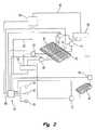
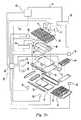
患者支持体23の典型的な実施形態が、図2、図2a、図2b、図2cの概略展開図に示されている。患者支持体23は、袋40、42、44、46、48を含む与圧袋又は支持ゾーン群を備える。図2、図2a、図2b、図2cに、袋40、42、44、46、48内の流体圧を調節する圧力制御システム又は流体供給システム50が概略的に示されている。袋40、42、44は患者と患者支持面24との間の界面圧を低減し、圧力潰瘍の形成を防ぐように設計されている。袋40、42、44は従来知られている治療目的に使用してもよい。図2cに示すように、袋46、48は、患者を移動させるか、又はベッドリネンを交換する等の際に介護者が患者を寝返りさせるのを助けるために使用されるよう設けられている。袋46、48は、通常、収縮されているが、患者を寝返りさせたい場合に、2つの袋46、48のうち一方を、膨張させればよい。 An exemplary embodiment of the
第1袋40は第1部分30内で頭端26の近くに配置され、患者支持面24上の患者の頭端26に近い部分を支える。第1袋40は通常、患者の頭と上部胴体を支持する。第2袋42は第2部分32内で頭端26と足端28の間のほぼ中央に配置され、患者支持面24上の患者の頭端26と足端28の間の中央に近い部分を支える。第2袋42は通常、患者の骨盤部又は中央部分を支持する。第3袋44は第3部分44内で足端28の近くに配置され、患者支持面24上の患者の足端28に近い部分を支える。第3袋44は通常、患者の下肢と踵を支持する。 The
図2cの実施形態において、圧縮可能又は伸長可能な発泡支持体52が、第3部分34内で第2袋42と第3袋44の間に配置されている。発泡体52が伸長収縮することで第3部分44の伸長収縮が可能であるので、第3部分34の長さは、第3袋44が患者の踵を支持する位置になるよう調整できる。発泡体52は、通常、患者支持面24上で大きな界面圧を発生しない患者の両方の大腿と上部ふくらはぎの一部を支持するよう配置される。発泡トッパー(不図示)が袋40、42、44と伸長可能な発泡体52との上に掛けられ、患者支持体23のほぼ連続的な上部層を形成する。患者支持体23として使用する他の適切な構造体が米国特許第6,378,152B1号、発明の名称「MATTRESS STRUCTURE」と米国特許第6,505,368B1号、発明の名称「MATTRESS ASSEMBLY」に開示されている。これら両方の特許の開示を本明細書に援用する。 In the embodiment of FIG. 2 c, a compressible or extensible foam support 52 is disposed in the
例示の本実施形態では、袋40、42、44、46、48は膨張可能な空気袋であるが、別の実施形態は、他の流体、即ち気体又は液体が充填されている与圧可能な袋を使用してもよい。図2は、圧力制御システム50を概略的に示す。圧力制御システム50は、袋40、42、44内の流体圧を調節し、第1、第2、第3袋40、42、44のうち1つ以上の袋内の流体圧を監視するための圧力変換器等の第1、第2、第3圧力検知デバイス54、56、58のうち1つ以上を含む。図2の実施形態において、センサ54、56、58は上記複数の袋内に設置される。即ち、デバイス54は、第1袋40内の流体圧を測定するために第1袋40内に設置される。デバイス56は、第2袋42内の流体圧を測定するために第2袋42内に設置される。デバイス58は、第3袋44内の流体圧を測定するために第3袋44内に設置される。例示の本実施形態では、圧力検知デバイス54、56、58の測定値が配線を介して制御部60に送信される。 In this exemplary embodiment, the
他の実施形態では、センサ54、56、58は袋内に配置されていない。図2aに示した実施形態では、センサは制御部と袋との間にあり、1つ以上の袋と制御部60とに流体連通線と電気配線55、57、59を介して結合され、当分野で知られた末端検知機構を提供する。末端検知システムの例は、本発明の譲受人により製造されるVersaCare(登録商標)製品とZonecare(登録商標)製品に見ることができる。 In other embodiments, the
図2bに示す別の実施形態では、センサ54、56、58のうちの1つ以上は、バルブ66、68、70と直線上に並び、当分野で知られた基部検知システムを提供する。基部検知システムの例は、本発明の譲受人により製造されるTotalCare(登録商標)製品に見ることができる。 In another embodiment shown in FIG. 2b, one or more of the
より高い検知精度を提供し、及び/又は検知と制御部応答の間の時間遅延を低減するために、これらのセンサを袋内に配置することが望ましい場合がある。製造コストを削減するために、又は他の理由により、これらのセンサを例えば末端又は基部検知構成で袋外に配置することが望ましい場合がある。図2cに示すように、追加の圧力検知デバイス(不図示)が寝返り袋46、48内の圧力を監視するために配置されてもよい。 It may be desirable to place these sensors in a bag to provide higher detection accuracy and / or reduce the time delay between detection and controller response. In order to reduce manufacturing costs or for other reasons, it may be desirable to place these sensors outside the bag, for example in a terminal or base sensing configuration. As shown in FIG. 2c, an additional pressure sensing device (not shown) may be arranged to monitor the pressure in the rollover bags 46,48.
図示のように、袋40、42、44は互いに直接流体連通はしていない。各袋40、42、44は異なる流体圧を有していてよい。例示の本実施形態では、病院ベッド20の電源ボックス内に設置された圧縮機62等の空気供給源を、各袋40、42、44に加圧空気(周囲空気より高い圧力の空気)を選択的に供給するために使用する。或いは、加圧空気を袋40、42、44に供給するために送風機又は他の適切な装置を使用することができる。様々な空気取扱い回路を圧縮機62から放出された加圧空気を袋40、42、44へ送るために使用することができる。これによりこれら袋内の圧力を増加させることが出来る。例示の本実施形態では、空気圧縮機62は多岐管64に繋がる放出線63を有する。多岐管64から第1袋40への加圧空気の流れは、バルブ66により調節される。バルブ68は多岐管64から袋42への加圧空気の流れを調節し、バルブ70は多岐管64から袋44への加圧空気の流れを調節する。各バルブ66、68、70の動作は、制御部60によって制御される。 As shown, the
袋40、42、44には、圧縮機62によって多岐管64とバルブ66、68、70とを介して加圧空気を選択的に供給することができるだけでなく、袋40、42、44のうちの1つ以上の袋の流体圧を下げたい場合、選択的にかつ独立に排気することができる。この目的のために、排気バルブ72が第1袋40と流体連通し、排気バルブ74が第2袋42と流体連通し、排気バルブ76が第3袋44と流体連通している。各排気バルブ72、74、76の動作は制御部60によって制御される。図2において、各排気バルブ72、74、76がボックス78へ排気するよう描かれている。同様に、図示のように圧縮機62の取込み線61がボックス78と連通している。例示の本実施形態では、ボックス78は真空多岐管を表すが、別の実施形態では、バルブ72、74、76は、周囲環境へ排気し、取込み線61は周囲環境から空気を取込んでもよい。その場合、ボックス78は周囲環境を表す。袋40、42の出口に真空を適用する能力は、袋群の圧力の比較的急な変更を必要とする治療目的のために袋群を使用する場合に有利である場合がある。 The
下記においてより詳細に説明するように、圧力制御システム又は空気供給システム50は、第1袋40、第2袋42、第3袋44の流体圧を独立に調節する。これらの各袋は、異なる目標圧力を有してもよい。各袋の流体圧が個別、独立に目標圧力へ調整される。しかし、袋40、42、44の圧力調整は、同時に、又は異なる時間に、又は一定の時間間隔で発生してよい。 As will be described in more detail below, the pressure control system or
袋又は支持ゾーン40、42、44はそれぞれ、単一の比較的大きな袋の形態を取ってもよいし、互いに流体連通している複数のより小さな袋を有し、取込み又は充填バルブと排気バルブとを有する袋システムの形態を取ってもよい。例えば、袋システム40が、互いに流体連通しほぼ同じ流体圧となる一連の小さな袋によって構成されてもよい。しかし、袋システム40の各小さな袋は、袋システム42、44の小さな袋とは連通していない。 Each bag or
或いは、袋40は、取込み又は充填バルブと排気バルブとをそれぞれ有し、独立に制御部60によって制御される小さな袋から成るシステムであってもよい。この種類の袋システムの場合、袋システム40の各小さな袋は、共通の目標圧力を持つ共通のプログラムに従って制御され、一方、袋システム42の各小さな袋は、袋システム40の小さな袋とは異なる目標圧力を持つ別の共通のプログラムに従って制御される。 Alternatively, the
例示の本実施形態では、袋又は支持ゾーン40、42、44はそれぞれ、互いに流体連通している小さな袋から成るシステムであり、バルブ66、68、70がそれぞれ、袋集合40、42、44への加圧流体の流入を調節し、バルブ72、74、76がそれぞれ、袋集合40、42、44からの流体の放出を調節する。図2の破線41は、袋40と袋42との分割を示す。本実施形態では、各バルブ66、68、70、72、74、76は通常のDC12Vソレノイド弁である。 In the illustrated embodiment, the bags or
また、ベッド20は、患者支持体23が搭載される重量枠とベッド枠との間に配置された複数の負荷セル80を備える。負荷セル80は制御部60と連通し、患者の体重を監視するのを可能にする。患者の体重を検出するための病院ベッド上におけるこのような負荷セルの使用は、当分野においてよく知られている。 The bed 20 includes a plurality of
ベッド20は、ベッドの縦軸に対する第1部分30又は第1袋40の高さの変化を監視する角度センサ等の頭部角度モニター31を備えてもよい。1つの実施形態では、第1部分30を曲げることで第1袋40が枠22に対して持上げられる。直線アクチュエータ29が第1部分30の曲げ伸ばしを駆動する。直線アクチュエータ29は、モーター(不図示)によって駆動される電位差計31を備える。電位差計31の駆動輪の回転が電位差計31の抵抗値を変化させ、直線アクチュエータ29の長さの表示を提供する。直線アクチュエータ29の長さを、制御部60が枠22の縦軸に対する第1部分30の曲げ角度と第1袋40の曲げ角度とに相関させる。第1袋40の曲げ角度を検出する他の適切な手段、例えばボールスイッチを使用してもよい。ボールスイッチは第1部分30又は第1袋40に結合されるか又は一体化されてよい。 The bed 20 may include a head angle monitor 31 such as an angle sensor for monitoring a change in the height of the
プログラム可能な制御部60はデバイス54、56、58によって検知された圧力値を監視し、圧縮機62及びバルブ66、68、70、72、74、76の動作を制御することで袋40、42、44内の流体の圧力を個別に調節するよう構成されている。空気システム制御部60はまた、負荷セル80と、第1部分30に結合された頭部モーター電位差計とから入力を受信し、それにより患者体重と第1部分30の位置を、袋又は支持ゾーン40、42、44内の流体圧を調節するために使用することができる。袋40、42、44内の流体圧を調節するために任意の適切なコントローラ又は複数のコントローラを使用することができる。本実施形態では、制御部60は、米国Atmel社製の8051系CMOSコントローラであるAtmel・T89C51CC01コントローラである。 The
ベッド20は、米国ヒル‐ロム社製VersaCare(登録商標)ベッドに概ね類似した構造を有していてもよい。本発明を使用するのに容易に適合させることができる別のベッド構造が、米国特許第5,715,548号、発明の名称「CHAIR BED」に開示されている。この特許の開示を本明細書に援用する。 The bed 20 may have a structure that is generally similar to a VersaCare® bed manufactured by Hill-Rom, USA. Another bed structure that can be easily adapted to use the present invention is disclosed in US Pat. No. 5,715,548, entitled “CHAIR BED”. The disclosure of this patent is incorporated herein by reference.
袋40、42、44、46、48内の流体圧を調節する圧力制御システム又は空気供給システム50の動作を説明する。これらの袋に対して6つの主要な動作モードが存在する。(1)第1に右寝返り補助、(2)第2に左寝返り補助、(3)最大膨張モード、(4)圧力緩和モード、(5)就寝、(6)オフの6つである。 The operation of the pressure control system or
<寝返り補助モード>
寝返り袋46、48は、右寝返り補助モードと左寝返り補助モードを除く各モードにおいて収縮されている。右寝返り補助モードでは、袋46は膨張され、袋48は収縮される。左寝返り補助モードでは、袋48は膨張され、袋46は収縮される。これら寝返り補助モードのいずれかに入ると、患者が回転し患者支持面24によって画定される主要面に対して約20度になるよう選択された袋が膨張される。膨張した寝返り袋は10秒間静止し、警報を鳴らした後、急速に収縮する。寝返り袋の膨張は、例えばリネン交換、衣類交換、ベッドパニング、背中の介護、及び他の介護処置において患者を回転させる時に、介護者を助けるために使用される。<Rolling assist mode>
The turnover bags 46 and 48 are contracted in each mode except the right turnover assist mode and the left turnover assist mode. In the right turn assist mode, the bag 46 is inflated and the bag 48 is deflated. In the left turn assist mode, the bag 48 is inflated and the bag 46 is deflated. Upon entering either of these turn assist modes, the patient is rotated and the selected bag is inflated to be approximately 20 degrees relative to the major surface defined by the
<最大膨張モード>
最大膨張モードは、第1袋40、第2袋42、第3袋43のそれぞれを最大動作圧力まで与圧し、硬い患者支持面を提供する。最大膨張モードは、例えば患者がベッドに入るか又は出る時、又は食事をする時、短い時間の間だけ使用される。本実施形態では、袋40、42内の圧力は、25〜29inAqの圧力範囲内に維持される。同様に、ベッドをCPR状態にした時、袋40、42内の流体圧は20〜30inAqの圧力範囲内に維持される。<Maximum expansion mode>
The maximum inflation mode pressurizes each of the
<圧力緩和モード>
圧力緩和モードは、各袋40、42、44の圧力を目標圧力に、又は許容圧力範囲内に、又は目標圧力の許容誤差内に維持することにより患者支持面24と患者との間の界面圧を低減することを試みるモードである。下記により詳細に説明するように、袋又は支持ゾーン40、42、44のそれぞれに対して別々の目標圧力又は許容圧力範囲が規定される。これらの目標圧力又は許容圧力範囲は、患者体重の関数として決定される。袋40、42の場合、許容圧力範囲はベッド20の縦軸に対する第1部分30の姿勢、又は頭角度の関数でもある。<Pressure relaxation mode>
The pressure relaxation mode is the interface pressure between the
袋40、42、44のうちの1つの袋内の圧力が目標圧力又は許容圧力範囲からずれると、時間遅延経過前に目標圧力又は許容範囲に戻っていなければ、その袋内の流体圧は圧力制御システム50の動作によって調整される。袋内圧力の調整の前に経過しなければならないこの期間又は時間遅延は、予め決められた長さを持っていない。この長さは検知された圧力の許容圧力範囲からのずれに関連する幾つかの変数によって変わる。 If the pressure in one of the
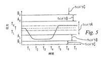
袋40、42、44のうちの1つの袋の圧力の調整に関連する時間遅延は、図5〜図7を参照すると、容易に理解できる。図5〜図7はそれぞれ、袋40、42、44のうちの1つの袋内の検知された圧力を示す時間チャートである。図5〜図7は、圧力値の検出に続く、異なる長さの期間の経過後に調整動作を開始する3つの代表的な圧力調整シナリオを例示する。図5〜図7は、個別、独立に監視され調整される袋40、42、44のうちの1つだけの圧力に関している。従って、他の2つの袋の圧力は、それぞれの圧力測定値に基づいて、図5〜図7のチャートに示された監視及び調整方法に従って監視され調整される。 The time delay associated with adjusting the pressure of one of the
袋40、42、44内の圧力は個別、独立に調整されるが、これらの袋の幾つか又は全部の圧力調整は、同時に又は一定の時間間隔で行われてもよい。例えば、これらの袋の2つ以上が許容範囲外であり、収縮させる必要がある場合、両方の袋の収縮が同時又はほぼ同時に起こってもよい。しかし、2つ以上の袋を膨張させる必要がある場合、それらの袋を同時ではなく順次膨張させる必要がある場合がある。袋を順次膨張させる場合、各袋に膨張の順番を決める優先度を割当ててもよい。例えば、最も短い時間において、検知された値と計算された値との差が最も大きい(即ち、最少時間における最大の圧力変化があった)袋に、最も高い優先度を割当ててもよい。また、ベッド20の頭部の曲げ伸ばしが優先度に影響してもよい。例えば、頭部が30度を超えて曲げられた場合、座部袋に、頭部袋より高い優先度を割当て、先に膨張させてもよい。袋の位置(即ち、足部、頭部、座部)を含む他の要因を調整の優先度を決定するために使用してもよい。 Although the pressure in the
図5〜図7において、圧力Tは袋の圧力を維持することが望まれる目標圧力である。圧力AL及びAUは、それぞれ許容圧力範囲、即ちウィンドウAの下限と上限とを表す。袋内の流体圧が、ウィンドウAを画定する圧力AL及びAUによって画定された圧力範囲内にある時、その圧力は許容され、許容範囲内にある限り圧力調整は行われない。例示の本実施形態では、目標圧力Tは、ウィンドウAの中心点である。しかし、別の実施形態では、ウィンドウAを画定する許容範囲の上限と下限は目標圧力値から等距離でなくてもよい。5-7, the pressure T is the target pressure that is desired to maintain the bag pressure. The pressures AL and AU represent the allowable pressure range, that is, the lower limit and the upper limit of window A, respectively. When the fluid pressure in the bag is within the pressure range defined by the pressures AL and AU defining window A, the pressure is allowed and no pressure adjustment is made as long as it is within the tolerance range. In the illustrated embodiment, the target pressure T is the center point of window A. However, in another embodiment, the upper and lower tolerance limits defining window A may not be equidistant from the target pressure value.
ベッド20上の患者は、患者支持面24上で自身の姿勢を時々変えるであろう。自身の姿勢を変える時、袋40、42、44のうち1つ以上の袋内の流体圧の変動を多分引き起こす。患者が姿勢を変えようとすることによる圧力変動によって、袋40、42、44のうち1つ以上の袋内の流体圧が、ウィンドウAによって画定された許容圧力範囲外の値になる場合がある。しかし、患者が新しい姿勢となり患者支持面24上での動きを止めた後、袋40、42、44内の圧力測定値は再び安定するであろう。患者がどう姿勢を変えたかに依って、新しく安定した流体圧が、ウィンドウAによって画定された許容圧力範囲内にある場合とない場合がある。 Patients on the bed 20 will sometimes change their posture on the
患者が姿勢を変えている間に1つの袋内の流体圧を積極的に調整すると、患者支持面24上で患者が新しい姿勢となり袋内の流体圧が再安定した後、調整を元に戻す必要がある場合がある。また、姿勢変更時、患者が袋40、42、44の膨張及び/又は収縮に反応し、それにより圧力変動と応答した調整の期間が長くなる場合がある。圧力値がウィンドウAの許容範囲外にあることを最初に検出した後、流体圧の調整を遅延させることで、これらの不要な流体圧調整の幾つかを避けることができる。 If the fluid pressure in one bag is positively adjusted while the patient is changing posture, the patient is in a new posture on the
袋内の流体圧が許容圧力範囲からかなりずれる場合は、流体圧を許容できる値に戻す時の遅延は望ましくない場合がある。例えば、圧力が許容範囲から上にかなりずれると、袋が損傷する場合がある。一方、圧力が許容範囲から下にかなりずれると、患者が「底打ち」し袋の下の構造体に直接受止められる場合がある。このような結果の可能性を制限するために、第2のウィンドウ又は圧力値範囲が、上記許容圧力範囲の直ぐ外の上と下両側に規定される。この第2の範囲の組み、即ちウィンドウBはウィンドウAの下、圧力値ALとBLの間と、ウィンドウAの上、圧力値AUとBUの間である。If the fluid pressure in the bag deviates significantly from the allowable pressure range, a delay in returning the fluid pressure to an acceptable value may not be desirable. For example, the bag can be damaged if the pressure deviates significantly from an acceptable range. On the other hand, if the pressure deviates significantly from an acceptable range, the patient may “bottom” and be received directly by the structure under the bag. In order to limit the possibility of such a result, a second window or pressure value range is defined on both the upper and lower sides just outside the allowable pressure range. This second set of ranges, window B, is below window A, between pressure values AL and BL and above window A, between pressure values AU and BU.
AUとALの値は、袋内の圧力がウィンドウA内にある時、患者と患者支持面の間の予期される界面圧がベッド20上の患者に圧力緩和を提供するように選択される。BLとBUの値は、袋内の圧力がウィンドウA外になりウィンドウBに入った時、当該袋と患者の間の予期される界面圧が、直ちに圧力を調整する必要がなく、短時間の間許容できるように選択される。例えば、本実施形態のウィンドウBを規定する圧力値は、ウィンドウBの条件から結果として予期される界面圧が約30分〜約2時間の間許容できるように選択される。下記により詳細に説明するように、袋40、42、44のうち1つの袋内の圧力がウィンドウBに入ると、可変期間の間に圧力がウィンドウAに戻らない場合にだけ積極的な圧力調整を開始する。この期間の長さは可変であるが、本実施形態では最大約5分の制限を設けている。もしウィンドウB内の圧力値を検出した後、この最大時間経過後にまだウィンドウAに戻っていない場合で圧力調整が開始されていない場合は、圧力制御システム50は圧力調整を開始する。 AUAnd ALThe value of is selected such that when the pressure in the bag is within window A, the expected interface pressure between the patient and the patient support surface provides pressure relief to the patient on the bed 20. BLAnd BUThe value of is that when the pressure inside the bag goes out of window A and enters window B, the expected interfacial pressure between the bag and the patient does not need to be adjusted immediately and is acceptable for a short time. Selected as. For example, the pressure value defining window B of this embodiment is selected such that the interface pressure expected as a result of the window B condition is acceptable for about 30 minutes to about 2 hours. As will be described in more detail below, when the pressure in one of the
なお、例えば、異なる許容時間を有する異なる範囲外条件に対応して、多数のこのようなウィンドウB(即ち、B1、B2、B3等)が存在してもよい。この場合、調整期間の遅延時間は各ウィンドウB1〜BNごとに異なる。即ち、遅延時間は測定された圧力がどのウィンドウB1〜BNにあるかに依って異なる。Note that, for example, there may be a large number of such windows B (ie, B1 , B2 , B3, etc.) corresponding to different out-of-range conditions with different permissible times. In this case, the delay time of the adjustment period is different for each of the windows B1 to BN. That is, the delay time varies depending on which window B1 -BN the measured pressure is in.
BUより上の圧力値とBLより下の圧力値は、圧力値の追加の範囲、即ちウィンドウCを規定する。袋の圧力がウィンドウC内に入ると、通常、効果的な圧力緩和を患者に提供しない。袋の圧力は、ウィンドウC内に入ると、より小さな圧力ずれのウィンドウBの場合の時間遅延より短い時間内に調整される。例えば、ウィンドウC内の圧力値の検出と当該袋内の圧力調整の開始との間の時間が0〜60秒の範囲内としてもよい。例示の本実施形態では、ウィンドウC内の圧力値が検出された後、当該袋内の圧力調整が約30秒以内に開始される。Pressure values above BU and pressure values below BL define an additional range of pressure values, ie window C. Once the bag pressure enters window C, it typically does not provide effective pressure relief to the patient. Once in the window C, the bag pressure is adjusted in a time shorter than the time delay for window B with a smaller pressure differential. For example, the time between the detection of the pressure value in the window C and the start of pressure adjustment in the bag may be in the range of 0 to 60 seconds. In the present exemplary embodiment, after the pressure value in the window C is detected, the pressure adjustment in the bag is started within about 30 seconds.
図5と図6のチャートを比較すると許容圧力範囲からのずれ量の差により、圧力調整の応答時間が異なることが分かる。図5は流体圧が、時間T1からT2の間に目標圧力からウィンドウB内へ下方へずれるがウィンドウC内には達していない場合を示す。この場合、圧力制御システム50は、圧力調整を直ちに開始せず、時間T4までに圧力が許容圧力範囲に戻っていない場合に圧力調整を開始する。一方、図6は圧力が、ウィンドウAから上方へかなりずれ、ウィンドウBを通ってウィンドウC内の圧力に達している場合を示す。圧力BUより上のウィンドウC内のこの値が検出されると、袋内の圧力調整が時間遅延なしで開始される。図6は圧力オーバーシュートをウィンドウA内の所望の圧力に修正する前にウィンドウAより僅かに低い値に修正することを示す。Comparing the charts of FIG. 5 and FIG. 6, it can be seen that the response time of the pressure adjustment differs depending on the difference in deviation from the allowable pressure range. Figure 5 shows the case where the fluid pressure, but deviates from the target pressure during the time T1 of the T2 downwards into the window B does not reach the window C. In this case, the
本実施形態では、初期調整又は修正動作(例えば、加圧空気の当該袋への制御された導入又は部分排気)後、測定された圧力がウィンドウA内にない場合、第2の調整が行われる。この場合、圧力値に関係なく短い遅延期間、例えば約20秒が必要となる。現在の圧力値に基づいて次の調整が行われる。 In this embodiment, after the initial adjustment or correction action (eg, controlled introduction or partial evacuation of pressurized air into the bag), the second adjustment is made if the measured pressure is not in window A. . In this case, a short delay period, for example, about 20 seconds is required regardless of the pressure value. The following adjustments are made based on the current pressure value.
圧力が積極的に調整され、ウィンドウAの許容圧力範囲内に戻った時、調整によって戻そうとした目標圧力は、図6の場合のように実際の中心目標圧力Tではないことに注意されたい。Tより僅かに低いTLとTより僅かに高いTUの2つの境界値が使用される。圧力は、図5に示すように、これら2つの値のうちの1つに戻される。ウィンドウAの許容範囲に戻すために圧力を下げる場合、圧力はTLに戻され、ウィンドウAの許容範囲に戻すために圧力を上げる場合、圧力はTUに戻される。従って、圧力がウィンドウAの下方にずれた図5において、調整を開始するために、圧力はTUに戻され、圧力がウィンドウAの上方にずれた図6において、調整を開始するために、圧力はTLに戻される。図6及び図7は簡略化されており、圧力値TUとTLの線を圧力値Tの線と分けて示していない。同様に、図の明確さのために、ウィンドウA、B、及びCは図5だけにおいてラベル付けされている。It should be noted that when the pressure is positively adjusted and returned to within the allowable pressure range of window A, the target pressure to be returned by adjustment is not the actual central target pressure T as in FIG. . Two boundary values slightly higher TU slightly below TL and T from T is used. The pressure is returned to one of these two values, as shown in FIG. When lowering the pressure to return to the acceptable range of the window A, the pressure is returned to TL, if raising the pressure to return to the acceptable range of the window A, the pressure is returned to TU. Thus, in FIG. 5 the pressure shifted downward of the window A, to initiate the adjustment, the pressure is returned to TU, 6 the pressure deviation above the window A, to initiate an adjustment, The pressure is returned toTL . 6 and 7 are simplified, not shown separately from the line pressure value T a line pressure value TU and TL. Similarly, for clarity of illustration, windows A, B, and C are labeled only in FIG.
許容圧力範囲からのずれがより大きい場合に、圧力調整の開始に関連する時間遅延が2つの異なる固定値のいずれかでありその結果、時間遅延が短くなるシステムが提供される。例えば、固定の時間遅延、圧力がウィンドウB内へずれた時は例えば5分又は10分を、圧力がウィンドウC内へずれた時は例えば30秒又は1分を使用することで、可変の時間遅延を有するシステムが提供される。しかし、ずっと大きな柔軟性を提供するためにより洗練されたシステムを使用することができる。 When the deviation from the allowable pressure range is greater, a system is provided in which the time delay associated with initiating pressure regulation is one of two different fixed values, resulting in a shorter time delay. For example, using a fixed time delay, eg 5 minutes or 10 minutes when the pressure is shifted into window B, and 30 seconds or 1 minute when the pressure is shifted into window C, for a variable time. A system with delay is provided. However, more sophisticated systems can be used to provide much greater flexibility.
例示の本実施形態は、検出された圧力がウィンドウCに入った場合に、短い固定の時間遅延を使用するが、圧力がウィンドウBに入った場合は、圧力測定値の安定性の関数である時間遅延を使用する。図5と図7から分かるように、袋内の圧力がウィンドウBに入った場合、圧力が所定の期間ウィンドウB内で比較的安定であった時に、又はウィンドウAに戻ることなく最大時間が経過した時にだけ、ウィンドウAへ圧力を戻す積極的圧力調整が行われる。 This exemplary embodiment uses a short fixed time delay when the detected pressure enters window C, but if the pressure enters window B, it is a function of the stability of the pressure measurement. Use time delay. As can be seen from FIGS. 5 and 7, when the pressure in the bag enters the window B, the maximum time elapses when the pressure is relatively stable within the window B for a predetermined period of time or without returning to the window A. Only when this is done will the positive pressure adjustment be made to return pressure to window A.
図5は、圧力がウィンドウB内へずれ、およそ時間T2から時間T4までウィンドウB内で安定であり、時間T4で圧力調整が開始される場合を示す。図7の場合は、圧力がウィンドウB内へずれ、時間T2から時間T4後までウィンドウB内で変動する。そして、圧力はウィンドウB内で安定しおよそ時間T5から時間T7まで比較的安定であり、時間T7で圧力が積極的に調整されウィンドウAへ戻される。5, shift pressure to the window B, are stable within the window B from approximately time T2 to time T4, showing a case where the pressure adjusting is started at time T4. In the case of FIG. 7, the pressure shifts into the window B and fluctuates in the window B from time T2 to time T4 . The pressure is relatively stable from a stable approximately time T5 in the window B to time T7, the pressure at time T7 is returned to be adjusted actively window A.
図から分かるように、図7の場合にウィンドウB内での初期の圧力変動は、圧力調整を遅らせ、ウィンドウB内で安定した後に行われる。圧力がウィンドウB内に留まり不規則に変動する場合、最大時間遅延期間、本実施形態では約10分が経過した後、調整が行われる。なお、図5〜図7に示された圧力軌跡は、本システムの動作を説明するために選択された理想化した軌跡であり、「安定な」圧力測定値は、図に示した一貫性のある特性を通常、有していないであろう。圧力の安定性は様々な方法で判定することができる。例えば、現在の圧力値を最新の圧力測定値の変動する平均値と比較し、現在の圧力値がその変動する平均値の周りの所定の範囲内に所定の期間留まる場合に、その圧力は安定したと考えることができる。例示の本実施形態で圧力の安定性を評価するために使用するプロセスを下記により詳細に説明する。 As can be seen from FIG. 7, in the case of FIG. 7, the initial pressure fluctuation in the window B is performed after the pressure adjustment is delayed and stabilized in the window B. If the pressure stays in window B and fluctuates irregularly, the adjustment is made after the maximum time delay period, about 10 minutes in this embodiment, has elapsed. Note that the pressure trajectories shown in FIGS. 5-7 are idealized trajectories selected to explain the operation of the system, and the “stable” pressure measurements are consistent with the consistency shown in the figures. It will usually not have certain properties. Pressure stability can be determined in various ways. For example, if the current pressure value is compared to the changing average value of the latest pressure measurement and the current pressure value stays within a specified range around the changing average value, the pressure is stable. Can be considered. The process used to assess pressure stability in this exemplary embodiment is described in more detail below.
図5〜図7において、境界値T、TU、TL、AU、AL、BU、BLはすべて、時間経過に対して一定である。しかし、本実施形態では、下記により詳細に説明するように、これらの境界値は、患者体重、第1部分30の角度、及びマットレス上の患者の位置を含む他の変数の関数として決定されてもよい。これらの境界値は、例えばセンサが患者の姿勢が仰向け又はうつ伏せから座っているに変わったことを、又は患者がベッドの中央から端に又はその逆に移動したことを検出すると、変化してもよい。従って、境界値は時間とともに変化する場合がある。5 to 7, the boundary values T, TU , TL , AU , AL , BU , and BL are all constant over time. However, in this embodiment, these boundary values are determined as a function of other variables including patient weight, angle of
また、患者体重測定値を袋40、42、44内の流体圧の調整を遅延させるのに使用することができる。例えば、5ポンド以上の検出された患者体重の変化は、ベッド上の患者の移動を示唆することが多い。従って、5ポンド以上の患者体重の変化が検出された時はいつでも、袋圧力の調整を所定の期間、例えば30秒か60秒遅延させ、不要な圧力調整を制限することができる。 Patient weight measurements can also be used to delay adjustment of fluid pressure in the
<就寝モード>
就寝モードは、患者へのじゃまを最小限にするよう設計されている。袋圧力の調整に伴う空気圧縮機ノイズと患者支持面24の持上げ持下げは、患者の眠りを妨げる可能性がある。このようなじゃまを最小限にするために、8時間の長さの就寝モードが提供される。就寝モードは圧力緩和モードと同様に動作するが、圧力がウィンドウB内にある時に調整を開始するための最大遅延期間が約5分から約10分に増加され、ウィンドウC内にある時に調整を開始するための最大遅延期間が約30秒から約1分に増加される。また、就寝モードに入った時に、袋40、42、44内の圧力を調整する回数を最小にするために、許容圧力範囲であるウィンドウAを広げることも可能である。例示の本実施形態では、袋内の圧力の調整後、就寝モードに留まり、8時間が経過した後にのみ、通常の圧力緩和モードに戻る。或いは制御部の他の動作、例えば本システムをCPR(最大膨張)モードにすること、又は手動で制御部を通常の圧力緩和モードに戻すことにより就寝モードは終了する。<Sleeping mode>
The sleep mode is designed to minimize disruption to the patient. Air compressor noise and lifting and lowering of the
<オフモード>
オフモードは、本システムを停止させ、ベッド20の清掃又は保守を行う時、或いはベッド20が不使用の場合に使用される。オフモードは患者がベッド20を使用している時は、使用されない。本システムをオフモードから起動した時、本システムは圧力緩和モードで始まる。<Off mode>
The off mode is used when the system is stopped and the bed 20 is cleaned or maintained, or when the bed 20 is not used. The off mode is not used when the patient is using the bed 20. When the system is started from off mode, the system starts in pressure relief mode.
<座持上げ動作>
本マットレスが圧力緩和モードにあり、第1部分30の姿勢が約3度を超えて変化した時、座袋すなわち袋42に対して座持上げ手順が実行される。この手順では、袋42内の圧力が比較的高い圧力に増加され、次にウィンドウA内の目標圧力に戻される。袋42が特定の圧力値に対して2つの異なる容積を持つことができるので、この手順が使用される。座持上げ動作は、袋が目標圧力に対して所望の容積となっていることを保証する。このような座持上げ手順は当該分野で既知であり、ベッドの頭部である第1部分30が、この座袋の境界圧力値を変更するのに十分な量だけ持上げられる時に、使用される。しかし、例示の本実施形態は、第1部分30の角度が約3度以上変化する毎に、持上げか持下げかによらず、また袋40、42、44のいずれかの目標圧力が第1部分30の姿勢の変化によって変更されたか否かによらず、座持上げ手順を使用する。同様の座持上げ手順は、代わりに又は追加してマットレス上の患者の位置又は姿勢の変化によって起動されてもよい。例えば、センサが患者の姿勢が仰向け又はうつ伏せから座っているに変わったことを、又は患者がベッドの中央から端に又はその逆に移動したことを検出すると、袋42内の圧力を上記手順に従って調整してもよい。<Sitting lifting operation>
When the mattress is in the pressure relief mode and the attitude of the
<計算とフローチャート>
例示の本実施形態で使用される例としての式の組み、及び圧力制御システム50の動作の基礎となる命令論理を、図4、図4a、図4b、図5、図5a、図5b、図6のフローチャートを使って説明する。<Calculation and flowchart>
The example formula sets used in this exemplary embodiment and the instruction logic underlying the operation of the
第1部分30の姿勢が境界値を定義する公式のうちの幾つかによって使用される。次の領域が第1部分30の姿勢、即ち「頭部持上げ」に関して定義される。
圧力緩和モードにおける第1袋40の境界値に関して、次の公式を使用する。
頭部圧力=(患者体重/49.70)+((頭部持上げ/−77.4)+3.4)
ここで、「患者体重」は、ポンドの10分の1を単位とし、少数点を付けない患者の体重値であり、「頭部持上げ」は角度(°)である。「頭部圧力」の得られた値は、第1袋40の目標圧力値T(単位はinAq)である。次に、第1袋40のウィンドウAを画定する境界値が、次の表に従って決定される。
Head pressure = (patient weight / 49.70) + ((head lift / −77.4) +3.4)
Here, “patient weight” is a weight value of a patient without a decimal point in units of 1 / 10th of a pound, and “head lifting” is an angle (°). The obtained value of “head pressure” is the target pressure value T (unit is inAq) of the
第1袋40のウィンドウBのパラメータは、次の式に従って決定される。
頭部圧力=((患者体重/100)+1)*3
ここで、「患者体重」は、ポンドの10分の1を単位とし、少数点を付けない患者の体重値である。「頭部圧力」の得られた値は、ウィンドウBのパラメータを次の表に従って決定するために使用される。
Head pressure = ((patient weight / 100) +1) * 3
Here, the “patient weight” is a weight value of a patient without a decimal point in units of 1 / 10th of a pound. The obtained value of “head pressure” is used to determine the parameters of window B according to the following table.
圧力緩和モードにおける第2袋42の境界値に関して、次の公式を使用する。
頭部持上げが55°未満の場合、
座部圧力=(患者体重/31.10)+((頭部持上げ/12.2)+1.8)
頭部持上げが55°を超える場合、
座部圧力=((患者体重/50)+4)*((頭部持上げ/12.2)+1)
ここで、「患者体重」は、ポンドの10分の1を単位とし、少数点を付けない患者の体重値であり、「頭部持上げ」は角度(°)である。「座部圧力」の得られた値は、第2袋42の目標圧力値T(単位はinAq)である。次に、第2袋42のウィンドウAを画定する境界値は、次の表に従って決定される。
If the head lift is less than 55 °,
Seat pressure = (patient weight / 31.10) + ((head lift / 12.2) +1.8)
If the head lift exceeds 55 °,
Seat pressure = ((patient weight / 50) +4) * ((head lift / 12.2) +1)
Here, “patient weight” is a weight value of a patient without a decimal point in units of 1 / 10th of a pound, and “head lifting” is an angle (°). The obtained value of the “seat portion pressure” is the target pressure value T (unit: inAq) of the
第2袋42のウィンドウBのパラメータは、次の式に従って決定される。
座部圧力=((患者体重/50)+4)*((頭部持上げ/60)+1)
ここで、「患者体重」は、ポンドの10分の1を単位とし、少数点を付けない患者の体重値であり、「頭部持上げ」は角度(°)である。「座部圧力」の得られた値は、ウィンドウBのパラメータを次の表に従って決定するために使用される。
Seat pressure = ((patient weight / 50) +4) * ((head lift / 60) +1)
Here, “patient weight” is a weight value of a patient without a decimal point in units of 1 / 10th of a pound, and “head lifting” is an angle (°). The obtained value of “seat pressure” is used to determine the parameters of window B according to the following table.
圧力緩和モードにおける第3袋44の境界値に関して、次の公式を使用する。
踵部圧力=((患者体重/200)+1)
ここで、「患者体重」は、ポンドの10分の1を単位とし、少数点を付けない患者の体重値である。「踵部圧力」の得られた値は、第3袋44の目標圧力値T(単位はinAq)である。次に、第3袋44のウィンドウAを画定する境界値は、次の表に従って決定される。
Buttocks pressure = ((patient weight / 200) +1)
Here, the “patient weight” is a weight value of a patient without a decimal point in units of 1 / 10th of a pound. The obtained value of the “buttock pressure” is the target pressure value T (unit: inAq) of the
第3袋44のウィンドウBのパラメータは、次の式に従って決定される。
踵部圧力=((患者体重/200)+1)
ここで、「患者体重」は、ポンドの10分の1を単位とし、少数点を付けない患者の体重値である。「踵部圧力」の得られた値は、ウィンドウBのパラメータを次の表に従って決定するために使用される。
Buttocks pressure = ((patient weight / 200) +1)
Here, the “patient weight” is a weight value of a patient without a decimal point in units of 1 / 10th of a pound. The obtained value of “buttock pressure” is used to determine the parameters of window B according to the following table.
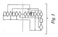
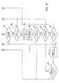
図3のフローチャートが、図3aと図3bとに詳細に示されており、袋40、42、44のうち1つに対する圧力制御システム50の自動遅延機能を説明している。自動遅延機能は、ボックス90、96、108、116によって表わされる4つの異なるステートを有している。ステート1、ボックス90は圧力がウィンドウA内にある状態に概ね対応する。ステート2は圧力がウィンドウB内にある状態に概ね対応する。ステート3は圧力がウィンドウC内にある状態に概ね対応する。ステート4は当該袋内の圧力の積極的調整の開始に対応する。 The flowchart of FIG. 3 is shown in detail in FIGS. 3a and 3b and describes the automatic delay function of the
図3に示すアルゴリズムによって使用される「MS」又は主要サンプル圧力値は、関連する圧力検知デバイスから得た5つの最新の圧力値を平均することで得られる。これらの値はそれぞれ100msに亘る圧力測定値を表わす。従って、例示の本実施形態では、MS値は直前の500msの間の当該袋内の圧力を表わす。 The “MS” or primary sample pressure value used by the algorithm shown in FIG. 3 is obtained by averaging the five most recent pressure values obtained from the associated pressure sensing device. Each of these values represents a pressure measurement over 100 ms. Thus, in the present exemplary embodiment, the MS value represents the pressure in the bag for the previous 500 ms.
ボックス90において、タイムアウトAは0にリセットされる(本システムがウィンドウA、ステート1から出た場合、タイムアウトAは圧力がウィンドウAから出た後、経過した時間を表わす)。ボックス92において、MS値を調べてウィンドウCに入ったか否かを判定する。ウィンドウCに入っている場合、本システムはボックス106へ進み、ウィンドウCのタイマーInCが起動される。ボックス92でMS値がウィンドウC内にない場合は、本システムはボックス94へ進み、MS値がウィンドウB内にあるか否かを判定する。MS値がウィンドウB内にない場合は、圧力はウィンドウA内にあるはずであり、本システムはボックス90へ戻る。ボックス94でMS値がウィンドウB内にあると判定した場合は、本システムはボックス96へ進み、ステート2に入る。ボックス98では、現在MS値を調べてMS値がウィンドウAに戻ったか否かを判定する。戻っている場合は、本システムは圧力調整を開始することなくボックス90へ戻る。現在MS値がウィンドウAの外にある場合は、本システムはボックス100へ進み、タイムアウトAを調べて圧力がウィンドウA外に出て5分を超えたか否かを判定する(就寝モードでは、この値は10分である)。5分を超えていれば、本システムはボックス116へ進み、圧力調整開始のフラグをセットする。圧力がウィンドウA外に出て5分未満である場合は、本システムはボックス102へ進み、圧力値の安定性を調べる(図4は後述のように圧力値の安定性の判定を説明している)。圧力が最近30秒間安定であった場合は、本システムはボックス116へ進み、袋の圧力調整を開始する。圧力が最近30秒間安定でなかった場合は、本システムはボックス104へ進み、現在MS値がウィンドウC内にあるか否かを判定する。現在MS値がウィンドウC内にない場合は、本システムはボックス96へ戻りステート2に留まる。現在MS値がウィンドウC内にある場合は、本システムはボックス106へ進み、ウィンドウCタイマーが起動される。 In box 90, timeout A is reset to 0 (if the system exits window A, state 1, timeout A represents the time elapsed since pressure exited window A). In
ウィンドウCタイマーを起動した後、ボックス108は、本システムがステート3にあることを示し、本システムは次にボックス110へ進む。ボックス110では、現在MS値を調べてウィンドウA内にあるか否かを判定する。ウィンドウA内にあれば、本システムは積極的な圧力調整をすることなくボックス90、ステート1へ戻る。ウィンドウA内になければ、本システムはボックス112へ進み、現在MS値がウィンドウB内にあるか否かを判定する。ウィンドウB内にあれば、本システムはボックス96、ステート2へ戻る。ウィンドウB内になければ、本システムはボックス114へ進み、本システムがステート3、ウィンドウCに15秒を超えているか否かを判定する。本システムがステート3になって15秒未満の場合は、本システムはボックス108を経由してボックス110へ戻る。本システムがステート3、ウィンドウCに15秒を超えている場合は、本システムはボックス116へ進みステート4に入り、調整レディーフラグをセットして圧力調整を開始する。調整レディーフラグをセットした後、本システムはボックス118へ進む。圧力調整手順が完了し調整レディーフラグがクリアされたか否かを判定する。調整レディーフラグがクリアされていれば、本システムはボックス90、ステート1へ戻る。調整レディーフラグがクリアされていなければ、本システムはボックス116へ戻りステート4に留まる。 After starting the window C timer,
図4には明示していないが、袋の圧力を積極的に調整する時、第1の調整を行った2秒後に圧力がウィンドウA内にあれば、調整レディーフラグがクリアされ、本システムはボックス90へ戻る。第1の調整を行った2秒後に圧力がウィンドウA内になければ、第2の調整を行う。第2の調整を行った後、調整レディーフラグがクリアされると、本システムはボックス90へ戻る。第2の調整後、20秒が経過すると袋圧力の追加の調整が許可される。 Although not explicitly shown in FIG. 4, when the bag pressure is positively adjusted, if the pressure is within the window A two seconds after the first adjustment, the adjustment ready flag is cleared and the system Return to box 90. If the pressure is not in
上記で説明したように、図3bの自動遅延フローチャートにおいて、ボックス102では、直前の30秒間、圧力が安定であったか否かを判定する。図4は、この判定を行うプロセスを表すフローチャートを示している。ボックス120では、袋40、42、44のうち1つに対する最新の圧力値群(少なくとも最新の5つの主要サンプル値を含む)を取得する。次に、本システムはボックス122へ進み、カウントに1を加算する。ボックス124では、カウントが5に達したか否かを判定する。達していなければ、カウントが5に達しボックス126へ進めるまで、本システムはボックス120へ戻る。ボックス126において、最新の5つの主要サンプル値の平均、即ち変動する平均値が計算される。ボックス128において、直前のMS値が、最新の5つの主要サンプル値の平均値と比較される。ボックス128においてその差が0.5inAqを超えている場合は、圧力が安定でないとして、安定性カウントを0に戻す。ボックス128においてその差が0.5inAq未満である場合は、圧力が安定であるとして、安定性カウントに1を加算する。従って、安定性カウントの値は、圧力が安定であった期間を表し、安定性カウント値が大きいほど、安定した圧力値の期間が長い。ボックス134では、上記平均値が現在のMS値として設定され、本システムはボックス120へ戻る。 As described above, in the automatic delay flowchart of FIG. 3b,
本発明を典型的な構成があるとして説明したが、本発明は、本開示の思想及び範囲内で更に変更されてもよい。従って、本出願は本発明の原理を使用するいかなる本発明の変更、使用、又は改作も含むよう意図されている。 While this invention has been described as having a typical configuration, this invention may be further modified within the spirit and scope of this disclosure. Accordingly, this application is intended to cover any variations, uses, or adaptations of the invention using its principles.
Claims (66)
Translated fromJapanese該患者支持体の少なくとも一部の上に患者が位置している時に、該患者を支えるよう配置された流体が入った1つ以上の袋と、
該1つ以上の袋に動作可能に結合され該1つ以上の袋内の流体圧を調節する圧力制御システムであって、該1つ以上の袋内の流体圧の検知された圧力値群を監視し、該1つ以上の袋内の流体圧を調整するようプログラムされたプログラム可能な制御部を備える圧力制御システムと、を備え、
圧力値の許容範囲が規定され、該検知された圧力値群の1つが該許容範囲外にあり、その1つの圧力値の検知に続く長さが可変である期間が、該1つ以上の袋内の流体圧が該許容範囲に戻ることなく経過した時に、該制御部は該1つ以上の袋内の流体圧の調整を開始し、
前記期間の長さは、前記1つの圧力値と前記許容圧力範囲との差の関数であり、
前記期間の長さは、複数の異なるアルゴリズムのうち選択された1つによって決定され、
該アルゴリズムは、前記1つの圧力値と前記許容圧力範囲との差の関数により選択される患者支持体。A patient support,
One or more bags containing fluid arranged to support the patient when the patient is positioned on at least a portion of the patient support;
A pressure control system operably coupled to the one or more bags to regulate fluid pressure in the one or more bags, wherein the sensed pressure values of the fluid pressure in the one or more bags are A pressure control system comprising a programmable controller programmed to monitor and regulate fluid pressure within the one or more bags;
A period during which a tolerance range of pressure values is defined, one of the detected pressure value groups is outside the tolerance range, and the length following the detection of the one pressure value is variable is the one or more bags. When the fluid pressure within has elapsed without returning to the allowable range, the controller initiates adjustment of the fluid pressure within the one or more bags,
The length of the period is a function of the difference between the one pressure value and the allowable pressure range,
The length of the period is determined by a selected one of a plurality of different algorithms;
The patient support is selected by a function of a difference between the one pressure value and the allowable pressure range.
前記第1のアルゴリズムによって決定された前記期間は、第1の最大値を有し、
前記第2のアルゴリズムによって決定された前記期間は、第2の最大値を有し、
該第1の最大値は該第2の最大値より大きい請求項2に記載の患者支持体。The second algorithm is selected when the difference between the one pressure value and the allowable pressure range exceeds the first window value;
The time period determined by the first algorithm has a first maximum value;
The time period determined by the second algorithm has a second maximum value;
3. A patient support according to claim 2, wherein the first maximum value is greater than the second maximum value.
前記第2のアルゴリズムによって決定された前記期間は、一定の長さを有する請求項3に記載の患者支持体。The period determined by the first algorithm has a variable length;
The patient support according to claim 3, wherein the period determined by the second algorithm has acertain length.
前記所定の期間は、30秒以上である請求項10に記載の患者支持体。The predetermined maximum value corresponds to a pressure difference of0.5 inAq (inches of water) in the one or more bags,
The patient support according to claim 10, wherein the predetermined period is30 seconds or more.
前記許容圧力範囲は、可変であり、
前記制御部は、該許容圧力範囲を該患者支持面の構成の関数として計算する請求項1に記載の患者支持体。The patient support surface is a connected surface having a plurality of configurations;
The allowable pressure range is variable,
The patient support according to claim 1, wherein the controller calculates the allowable pressure range as a function of the configuration of the patient support surface.
該圧縮機は該1つ以上の袋に加圧された流体を制御可能な送り方で送り、それにより選択的に該1つ以上の袋内の流体圧を調整し、
該圧力制御システムは、該1つ以上の袋と連通し流体の流れを調節するための1つ以上のバルブを更に備え、
該1つ以上のバルブの動作は、前記制御部によって制御される請求項1に記載の患者支持体。The pressure control system comprises a compressor in selective fluid communication with the one or more bags;
The compressor feeds the pressurized fluid into the one or more bags in a controllable manner, thereby selectively adjusting the fluid pressure within the one or more bags;
The pressure control system further comprises one or more valves in communication with the one or more bags for regulating fluid flow;
The patient support according to claim 1, wherein operation of the one or more valves is controlled by the controller.
該就寝モードの起動は、前記許容圧力範囲を広げ、
該制御部は、前記流体圧の調整後、該就寝モードに留まる請求項1に記載の患者支持体。The controller further defines a sleep mode of operation;
Activation of the sleep mode widens the allowable pressure range,
The patient support according to claim 1, wherein the control unit remains in the sleeping mode after the fluid pressure is adjusted.
該患者支持体の該頭端と足端との間のほぼ中央に配置され、患者が該患者支持体の該頭端と該足端との間の中心点の近くの部分上にいる時に該患者を支えるよう配置された流体が入った第2の袋と、を備え、
前記圧力制御システムは、該第1の袋と該第2の袋とに動作可能に結合され、該第1の袋内の第1流体圧と該第2の袋内の第2流体圧とを調節し、
該圧力制御システムは、該第1流体圧と該第2流体圧との検知された圧力値群を監視して、該第1流体圧と該第2流体圧とを個別に調整するようプログラムされたプログラム可能な制御部を備え、
圧力値の許容範囲が該第1の袋と該第2の袋それぞれに対して規定され、
該検知された圧力値群の1つが対応する該許容範囲外にあり、その1つの圧力値の検知に続く長さが可変である期間が、対応する一方の袋内の流体圧が対応する該許容範囲に戻ることなく経過した時に、該制御部は該第1流体圧と該第2流体圧とのうち対応する流体圧の調整を開始する請求項1に記載の患者支持体。A first bag containing fluid disposed near the head end of the patient support surface and disposed to support the patient when the patient is on a portion of the patient support surface close to the head end;
Positioned approximately midway between the head and foot ends of the patient support and the patient is on a portion of the patient support near the center point between the head and foot ends. A second bag containing fluid arranged to support the patient;
The pressure control system is operably coupled to the first bag and the second bag, and provides a first fluid pressure in the first bag and a second fluid pressure in the second bag. Adjust
The pressure control system is programmed to monitor a group of detected pressure values of the first fluid pressure and the second fluid pressure and individually adjust the first fluid pressure and the second fluid pressure. With programmable control units,
An acceptable range of pressure values is defined for each of the first bag and the second bag,
The period during which one of the detected pressure value groups is outside the corresponding allowable range and the length following detection of the one pressure value is variable, corresponds to the fluid pressure in the corresponding one of the bags. 2. The patient support according to claim 1, wherein the control unit starts adjusting the fluid pressure corresponding to the first fluid pressure and the second fluid pressure when the time has elapsed without returning to the allowable range.
前記圧力制御システムは、該第3の袋に動作可能に結合され、該第3の袋内の第3流体圧を調節し、
前記制御部は、該第3流体圧の検知された圧力値群を監視し、該第3流体圧を独立に調整するようプログラムされ、
圧力値の第3の許容範囲が、該第3の袋に対して規定され、
該検知された第3流体圧値群の1つが該第3の許容範囲外にあり、その1つの流体圧値の検知に続く長さが可変である第3の期間が、該第3の袋内の該流体圧が該第3の許容範囲に戻ることなく経過した時に、
該制御部は、該第3流体圧の調整を開始する請求項16に記載の患者支持体。A third bag disposed near the foot end of the patient support and containing a fluid disposed to support the patient when the patient is on a portion of the patient support close to the foot end;
The pressure control system is operably coupled to the third bag and regulates a third fluid pressure in the third bag;
The controller is programmed to monitor a group of detected pressure values of the third fluid pressure and independently adjust the third fluid pressure;
A third tolerance range of pressure values is defined for the third bag;
A third period in which one of the detected third fluid pressure value groups is out of the third tolerance range and the length following detection of the one fluid pressure value is variable is the third bag. When the fluid pressure within has elapsed without returning to the third tolerance range,
The patient support according to claim 16, wherein the control unit starts adjusting the third fluid pressure.
該第1部分と該第2部分と該第3部分とは相対的に曲げ伸ばし可能であり、前記第1の袋は該第1部分に配置され、前記第2の袋は該第2部分に配置され、前記第3の袋は該第3部分に配置されている請求項17に記載の患者支持体。The patient support is a bendable and extendable surface, and is disposed near the foot end, a first portion disposed near the head end, a second portion disposed in the center of the patient support surface, and the foot end. And a third part
The first portion, the second portion, and the third portion are relatively bendable and stretchable, the first bag is disposed on the first portion, and the second bag is disposed on the second portion. 18. A patient support according to claim 17, wherein the patient support is disposed and the third bag is disposed in the third portion.
前記第3の許容圧力範囲は、前記患者の体重の関数であり、該第1部分の姿勢が変化しても変化しない請求項18に記載の患者支持体。Each allowable pressure range for the first bag and the second bag is a function of the weight of the patient and the posture of the first portion;
19. The patient support according to claim 18, wherein the third allowable pressure range is a function of the patient's weight and does not change when the posture of the first portion changes.
前記第1の袋と前記第2の袋それぞれの前記許容圧力範囲は、更に前記患者の体重の関数である請求項19に記載の患者支持体。The patient support comprises a weight sensing device operably coupled to the controller;
20. A patient support according to claim 19, wherein the allowable pressure range for each of the first and second bags is further a function of the patient's weight.
前記第2部分に対して角度が可変であり、
該第1部分の所定の角度量の回転を検出すると、前記制御部は前記第2の袋を対応する前記許容圧力範囲より高い値に膨張させることを開始し、
次に該第2の袋を該許容圧力範囲に戻す請求項18に記載の患者支持体。The first part is
The angle with respect to the second part is variable;
When detecting the rotation of the first portion by a predetermined angular amount, the control unit starts to inflate the second bag to a value higher than the corresponding allowable pressure range,
19. A patient support according to claim 18, wherein the second bag is then returned to the allowable pressure range.
前記所定の角度量は、該水平な軸の周りの該第1部分の回動による上げ下げに関する方向を持っていない請求項21に記載の患者支持体。The first portion is generally rotatable around a substantially horizontal axis, and can be raised and lowered by turning around the horizontal axis;
The patient support according to claim 21, wherein the predetermined angular amount does not have a direction for raising and lowering due to rotation of the first portion about the horizontal axis.
該第1部分の動きにより該第2の袋の該許容圧力範囲が変化した時に、前記制御部によって膨張が開始される請求項23に記載の患者支持体。The allowable pressure range of the second bag is a function of the posture of the first portion of the foldable patient support surface;
24. The patient support according to claim 23, wherein when the allowable pressure range of the second bag changes due to the movement of the first portion, the control unit starts inflation.
前記所定の角度量は、該第2の袋の該許容圧力範囲の変化なしに、前記制御部による膨張の開始が可能なように設定されている請求項21に記載の患者支持体。The allowable pressure range of the second bag is a function of the posture of the first portion of the foldable patient support surface;
The patient support according to claim 21, wherein the predetermined angular amount is set so that the control unit can start inflation without changing the allowable pressure range of the second bag.
前記1つの圧力値と前記許容圧力範囲との差が第1のウィンドウ値を超えていない場合に、第1のアルゴリズムが選択され、
該1つの圧力値と該許容圧力範囲との差が該第1のウィンドウ値を超えている場合に、第2のアルゴリズムが選択され、
該第1のアルゴリズムによって決定される前記期間は、第1の最大値を有し、
該第2のアルゴリズムによって決定される前記期間は第2の最大値を有し、
該第1の最大値は、該第2の最大値より大きい請求項16に記載の患者支持体。For each of the first bag and the second bag,
A first algorithm is selected if the difference between the one pressure value and the allowable pressure range does not exceed a first window value;
A second algorithm is selected if the difference between the one pressure value and the allowable pressure range exceeds the first window value;
The time period determined by the first algorithm has a first maximum value;
The time period determined by the second algorithm has a second maximum value;
17. A patient support according to claim 16, wherein the first maximum value is greater than the second maximum value.
前記第2のアルゴリズムは、前記1つの圧力値と対応する前記許容圧力範囲との差が前記第1のウィンドウ値を超えていることを検出した後、直ちに前記第1流体圧と前記第2流体圧のうち対応する流体圧の調整を開始する請求項27に記載の患者支持体。The length of the period determined by the first algorithm is variable;
The second algorithmimmediately detects that the difference between the one pressure value and the corresponding allowable pressure range exceeds the first window value, andimmediately after that, the first fluid pressure and the second fluid. 28. A patient support according to claim 27, which starts adjusting the corresponding fluid pressure of the pressure.
該第1部分と該第2部分とは相対的に曲げ伸ばし可能であり、
前記第1の袋は該第1部分に配置され、前記第2の袋は該第2部分に配置されている請求項16に記載の患者支持体。The patient support surface is a bendable and extendable surface, and includes a first portion disposed near the head end and a second portion disposed in the center of the patient support surface;
The first part and the second part are relatively bendable and stretchable;
17. A patient support according to claim 16, wherein the first bag is disposed in the first portion and the second bag is disposed in the second portion.
該圧縮機は、該第1の袋と該第2の袋とに加圧された流体を制御可能な送り方で送り、それにより選択的に該第1の袋と該第2の袋内の流体圧を増加させる請求項16に記載の患者支持体。The pressure control system includes a compressor in selective fluid communication with the first bag and the second bag;
The compressor feeds pressurized fluid to the first bag and the second bag in a controllable manner of delivery, thereby selectively in the first bag and the second bag. 17. A patient support according to claim 16, which increases fluid pressure.
該1つ以上のバルブの動作は、前記制御部によって制御される請求項23に記載の患者支持体。The pressure control system further comprises one or more valves in communication with the first bag and the second bag for regulating fluid flow;
24. A patient support according to claim 23, wherein operation of the one or more valves is controlled by the controller.
該就寝モードは、前記許容圧力範囲を広げ、
該制御部は、流体圧の調整後、該就寝モードに留まる請求項16に記載の患者支持体。The controller further defines a sleep mode of operation;
The sleep mode extends the allowable pressure range,
The patient support according to claim 16, wherein the control unit remains in the sleeping mode after adjusting the fluid pressure.
該患者の体重の少なくとも一部を支えるための流体が入った1つ以上の袋を提供することと、
該1つ以上の袋内の流体圧を監視することと、
許容流体圧範囲を規定し、1つの流体圧値が該許容流体圧範囲外であると検出され、その流体圧値の検知に続く長さが可変である期間が、該1つ以上の袋内の流体圧が該許容流体圧範囲に戻ることなく経過した時にだけ、該1つ以上の袋内の流体圧を調整することで該1つ以上の袋内の流体圧を調節することと
を含み、
前記期間の長さは、前記1つの流体圧値と前記許容流体圧範囲との差の関数であり、
前記期間の長さは、複数の異なるアルゴリズムのうち選択された1つによって決定され、
該アルゴリズムは、前記1つの流体圧値と前記許容流体圧範囲との差の関数により選択される方法。A method of supporting a patient,
Providing one or more bags containing fluid to support at least a portion of the patient's weight;
Monitoring the fluid pressure in the one or more bags;
A range in which an allowable fluid pressure range is defined, one fluid pressure value is detected to be outside the allowable fluid pressure range, and the length following detection of the fluid pressure value is variable is within the one or more bags. Adjusting the fluid pressure in the one or more bags by adjusting the fluid pressure in the one or more bags only when the fluid pressure of the fluid has passed without returning to the allowable fluid pressure range. ,
The length of the period is a function of the difference between the one fluid pressure value and the allowable fluid pressure range;
The length of the period is determined by a selected one of a plurality of different algorithms;
The algorithm is selected by a function of a difference between the one fluid pressure value and the allowable fluid pressure range.
前記第1のアルゴリズムによって決定された前記期間は第1の最大値を有し、
前記第2のアルゴリズムによって決定された前記期間は第2の最大値を有し、
該第1の最大値は該第2の最大値より大きい請求項37に記載の方法。The second algorithm is selected when the difference between the one fluid pressure value and the allowable fluid pressure range exceeds the first window value;
The time period determined by the first algorithm has a first maximum value;
The time period determined by the second algorithm has a second maximum value;
38. The method of claim 37, wherein the first maximum value is greater than the second maximum value.
前記第2のアルゴリズムによって決定された前記期間は、一定の長さを有する請求項38に記載の方法。The period determined by the first algorithm has a variable length;
The method of claim 38, wherein the time period determined by the second algorithm has aconstant length.
前記所定の期間は、30秒以上である請求項45に記載の方法。The predetermined maximum value corresponds to a pressure difference of0.5 inAq (inches of water) in the bag,
46. The method of claim 45, wherein the predetermined period is30 seconds or longer.
前記許容流体圧範囲は可変であり、
該曲げ伸ばし可能な面の該構成の関数である請求項36に記載の患者支持体。The patient is supported on a bendable surface having a plurality of configurations;
The allowable fluid pressure range is variable,
37. A patient support according to claim 36, which is a function of the configuration of the bendable surface.
前記調節するステップは、該第1の袋と該第2の袋内の流体圧を同時に調整することを含む請求項36に記載の方法。The providing step includes providing a first bag and a second bag;
The method of claim 36, including adjusting the fluid pressure in the first bag and the second bagsimultaneously to the regulation.
前記調節するステップは、該第1の袋と該第2の袋内の流体圧を一定の時間間隔で調整することを含む請求項36に記載の方法。The providing step includes providing a first bag and a second bag;
38. The method of claim 36, wherein the adjusting step includes adjusting fluid pressure in the first bag and the second bag atregular time intervals.
袋内の流体圧を時間に亘って検知するよう動作可能なセンサと、
検知された圧力を監視し、
検知された圧力が上限と下限とを有する許容圧力範囲外か否かを判定し、
圧力の検知に続く所望の期間が、該袋内の流体圧が該許容圧力範囲に戻ることなく経過した後、該袋内の流体圧の調整を開始し、
該患者支持体の動作モードと、該患者支持体の構成と、該袋によって少なくとも部分的に支えられる人の特性とのうち少なくとも1つに基づいて該許容圧力範囲の該上限と下限とのうち少なくとも1つを変更し、
検知された圧力と該許容圧力範囲との差と、検知された圧力と該許容圧力範囲との該差に基づいて選択されたアルゴリズムとのうち少なくとも1つに基づいて該所望の期間を決定するようプログラムされたプログラム可能な制御部と、
を備える圧力制御システム。A pressure control system for adjusting fluid pressure within a patient support bag, comprising:
A sensor operable to detect fluid pressure in the bag over time;
Monitor the detected pressure,
Determine whether the detected pressure is outside the allowable pressure range having an upper limit and a lower limit,
After the desired period following pressure detection has elapsed without the fluid pressure in the bag returning to the allowable pressure range, the adjustment of the fluid pressure in the bag is started,
The upper and lower limits of the allowable pressure range based on at least one of an operating mode of the patient support, a configuration of the patient support, and a characteristic of the person at least partially supported by the bag Change at least one,
Determining the desired time period based on at least one of a difference between a sensed pressure and the allowable pressure range and an algorithm selected based on the difference between the sensed pressure and the allowable pressure range. A programmable control unit, programmed to
With pressure control system.
前記第1のアルゴリズムによって決定された前記期間は、第1の最大値を有し、
前記第2のアルゴリズムによって決定された前記期間は、第2の最大値を有し、
該第1の最大値は該第2の最大値より大きい請求項52に記載の圧力制御システム。A second algorithm is selected when the difference between the sensed pressure and the allowable pressure range exceeds the first window value;
The time period determined by the first algorithm has a first maximum value;
The time period determined by the second algorithm has a second maximum value;
53. The pressure control system of claim 52, wherein the first maximum value is greater than the second maximum value.
前記第2のアルゴリズムによって決定された前記期間は、一定の長さを有する請求項53に記載の圧力制御システム。The period determined by the first algorithm has a variable length;
54. The pressure control system of claim 53, wherein the period determined by the second algorithm has acertain length.
該空気供給源に結合された多岐管と、
前記袋に選択的に加圧空気を提供するために該多岐管と該袋とに結合されたバルブと、
を更に備える請求項51に記載の圧力制御システム。An air supply coupled to the controller;
A manifold coupled to the air source;
A valve coupled to the manifold and the bag to selectively provide pressurized air to the bag;
52. The pressure control system of claim 51, further comprising:
膨張可能な支持ゾーンを備える患者支持体のための空気供給システムを備え、
前記空気供給システムは、
空気供給源と、
該空気供給源に結合されたバルブと、
該支持ゾーンの空気圧を示す圧力信号を生成するよう動作可能な圧力センサと、
該支持ゾーンの目標圧力を決定し、該圧力信号を受信し、該支持ゾーン内の圧力が該目標圧力からずれているか否かを該圧力信号に基づいて判定し、該支持ゾーン内の圧力を調整する前に経過するべき期間を決定し、該期間が経過した後に該支持ゾーン内の圧力を調整するようプログラムされた空気システム制御部と、
を備える患者支持体。A patient support according to claim 1, comprising:
An air supply system for a patient support including an inflatable support zone,
The air supply system includes:
An air supply,
A valve coupled to the air source;
A pressure sensor operable to generate a pressure signal indicative of the air pressure of the support zone;
Determining a target pressure in the support zone, receiving the pressure signal, determining whether the pressure in the support zone deviates from the target pressure, and determining the pressure in the support zone An air system controller programmed to determine a period of time to elapse before adjusting and to adjust the pressure in the support zone after the period has elapsed;
Apatient support comprising:
前記目標圧力は該角度信号に少なくとも部分的に基づいて決定される請求項62に記載の患者支持体。An angle sensor operable to generate an angle signal indicative of an angle of the support zone relative to a longitudinal axis of the support zone;
64. Apatient support according to claim 62, wherein the target pressure is determined based at least in part on the angle signal.
前記制御部は、該期間の所望の長さを決定するよう更にプログラムされている請求項61に記載の患者支持体。The length of the period is adjustable,
62. Apatient support according to claim 61, wherein the controller is further programmed to determine a desired length of the period.
Applications Claiming Priority (5)
| Application Number | Priority Date | Filing Date | Title |
|---|---|---|---|
| US68934005P | 2005-06-10 | 2005-06-10 | |
| US60/689,340 | 2005-06-10 | ||
| US70264505P | 2005-07-26 | 2005-07-26 | |
| US60/702,645 | 2005-07-26 | ||
| PCT/US2006/022732WO2006135845A2 (en) | 2005-06-10 | 2006-06-12 | Control for pressurized bladder in a patient support apparatus |
Publications (3)
| Publication Number | Publication Date |
|---|---|
| JP2008545513A JP2008545513A (en) | 2008-12-18 |
| JP2008545513A6 JP2008545513A6 (en) | 2010-05-06 |
| JP5208732B2true JP5208732B2 (en) | 2013-06-12 |
Family
ID=37532864
Family Applications (1)
| Application Number | Title | Priority Date | Filing Date |
|---|---|---|---|
| JP2008516011AExpired - Fee RelatedJP5208732B2 (en) | 2005-06-10 | 2006-06-12 | Control means for pressurized bag in patient support device |
Country Status (5)
| Country | Link |
|---|---|
| US (3) | US8090478B2 (en) |
| EP (1) | EP1893822A4 (en) |
| JP (1) | JP5208732B2 (en) |
| AU (1) | AU2006257880B2 (en) |
| WO (1) | WO2006135845A2 (en) |
Families Citing this family (65)
| Publication number | Priority date | Publication date | Assignee | Title |
|---|---|---|---|---|
| WO2006135845A2 (en) | 2005-06-10 | 2006-12-21 | Hill-Rom Services, Inc. | Control for pressurized bladder in a patient support apparatus |
| US20080077020A1 (en) | 2006-09-22 | 2008-03-27 | Bam Labs, Inc. | Method and apparatus for monitoring vital signs remotely |
| US20110301432A1 (en) | 2010-06-07 | 2011-12-08 | Riley Carl W | Apparatus for supporting and monitoring a person |
| US8525680B2 (en) | 2009-09-18 | 2013-09-03 | Hill-Rom Services, Inc. | Apparatuses for supporting and monitoring a condition of a person |
| US8531307B2 (en)* | 2009-09-18 | 2013-09-10 | Hill-Rom Services, Inc. | Patient support surface index control |
| US20110083271A1 (en)* | 2009-10-09 | 2011-04-14 | Bhai Aziz A | Head of bed angle mounting, calibration, and monitoring system |
| US9420895B2 (en)* | 2009-12-17 | 2016-08-23 | Stryker Corporation | Patient support |
| CN103974681B (en) | 2010-09-01 | 2017-12-26 | 亨特莱技术有限公司 | Patient support and method |
| US8973186B2 (en) | 2011-12-08 | 2015-03-10 | Hill-Rom Services, Inc. | Optimization of the operation of a patient-support apparatus based on patient response |
| US9655795B2 (en)* | 2012-04-10 | 2017-05-23 | Hill-Rom Services, Inc. | Occupant support with a migration sensitive bladder and method for migration detection |
| EP2666406A3 (en) | 2012-05-22 | 2013-12-04 | Hill-Rom Services, Inc. | Occupant egress prediction systems, methods and devices |
| EP2667313B1 (en) | 2012-05-22 | 2021-08-04 | Hill-Rom Services, Inc. | Adverse condition detection, assessment, and response system |
| US9468307B2 (en) | 2012-09-05 | 2016-10-18 | Stryker Corporation | Inflatable mattress and control methods |
| US8839473B1 (en) | 2012-11-13 | 2014-09-23 | Alex Catala | Air mattress comfort adjustment system |
| US9333136B2 (en) | 2013-02-28 | 2016-05-10 | Hill-Rom Services, Inc. | Sensors in a mattress cover |
| US9801767B2 (en)* | 2013-03-14 | 2017-10-31 | Kap Medical, Inc. | Patient support apparatus and method |
| US8984687B2 (en) | 2013-03-14 | 2015-03-24 | Select Comfort Corporation | Partner snore feature for adjustable bed foundation |
| JP6110008B2 (en) | 2013-03-14 | 2017-04-05 | セレクト コンフォート コーポレーションSelect Comfort Corporation | Inflatable air mattress snoring detection and response |
| EP2967223B1 (en) | 2013-03-14 | 2017-11-15 | SleepIQ Labs Inc. | Inflatable air mattress with light controls |
| WO2014143634A1 (en) | 2013-03-14 | 2014-09-18 | Nunn Rob | Inflatable air mattress system with detection techniques |
| US8893339B2 (en) | 2013-03-14 | 2014-11-25 | Select Comfort Corporation | System and method for adjusting settings of a bed with a remote control |
| CA2906038C (en) | 2013-03-14 | 2018-02-13 | Select Comfort Corporation | Inflatable air mattress alert and monitoring system |
| WO2014152793A1 (en) | 2013-03-14 | 2014-09-25 | Nunn Rob | Inflatable air mattress system architecture |
| US9635953B2 (en) | 2013-03-14 | 2017-05-02 | Sleepiq Labs Inc. | Inflatable air mattress autofill and off bed pressure adjustment |
| DE102013104538B4 (en) | 2013-05-03 | 2015-05-21 | MAQUET GmbH | Operating table and method for controlling an operating table |
| US9504416B2 (en) | 2013-07-03 | 2016-11-29 | Sleepiq Labs Inc. | Smart seat monitoring system |
| US9445751B2 (en) | 2013-07-18 | 2016-09-20 | Sleepiq Labs, Inc. | Device and method of monitoring a position and predicting an exit of a subject on or from a substrate |
| CA2945694C (en) | 2013-12-30 | 2022-10-25 | Select Comfort Corporation | Inflatable air mattress with integrated control |
| US10674832B2 (en) | 2013-12-30 | 2020-06-09 | Sleep Number Corporation | Inflatable air mattress with integrated control |
| WO2016011403A1 (en) | 2014-07-18 | 2016-01-21 | Select Comfort Corporation | Automatic sensing and adjustment of a bed system |
| US9504620B2 (en)* | 2014-07-23 | 2016-11-29 | American Sterilizer Company | Method of controlling a pressurized mattress system for a support structure |
| EP2995242B1 (en) | 2014-09-11 | 2023-11-15 | Hill-Rom S.A.S. | Patient support apparatus |
| US10448749B2 (en) | 2014-10-10 | 2019-10-22 | Sleep Number Corporation | Bed having logic controller |
| EP3242576A4 (en) | 2015-01-05 | 2018-07-25 | Select Comfort Corporation | Bed with user occupancy tracking |
| US20160242561A1 (en)* | 2015-02-25 | 2016-08-25 | Rapid Air Llc | Airbed control system for simultaneous articulation and pressure adjustment |
| US11058227B2 (en) | 2015-04-23 | 2021-07-13 | Sealy Technology, Llc | Systems and methods for adjusting the firmness and profile of a mattress assembly |
| US10413464B2 (en)* | 2015-05-05 | 2019-09-17 | Hill-Rom Services, Inc. | Multi-mode sacral unloading pressure relief in a patient support surface |
| EP3482734B1 (en)* | 2015-06-15 | 2020-12-09 | Allen Medical Systems, Inc. | Spine table positioner pad with pressure sensing and cooling features |
| US10504353B2 (en) | 2015-07-27 | 2019-12-10 | Hill-Rom Services, Inc. | Customized bed exit warnings to modify patient behavior |
| US10149549B2 (en) | 2015-08-06 | 2018-12-11 | Sleep Number Corporation | Diagnostics of bed and bedroom environment |
| EP3205268B1 (en) | 2016-02-11 | 2023-10-25 | Hill-Rom Services, Inc. | Hospital bed |
| US11173085B2 (en) | 2017-12-28 | 2021-11-16 | Stryker Corporation | Mattress cover for a mattress providing rotation therapy to a patient |
| CN111770706B (en) | 2017-12-28 | 2023-06-02 | 数眠公司 | A bed with a snore detection feature |
| US11737938B2 (en) | 2017-12-28 | 2023-08-29 | Sleep Number Corporation | Snore sensing bed |
| US11246775B2 (en) | 2017-12-28 | 2022-02-15 | Stryker Corporation | Patient turning device for a patient support apparatus |
| US11071668B1 (en)* | 2018-06-04 | 2021-07-27 | Encompass Group, Llc. | Hospital bed with inflatable bladders with random inflation and related methods |
| USD877915S1 (en) | 2018-09-28 | 2020-03-10 | Stryker Corporation | Crib assembly |
| USD888962S1 (en) | 2018-09-28 | 2020-06-30 | Stryker Corporation | Cover assembly for a patient support |
| USD888963S1 (en) | 2018-09-28 | 2020-06-30 | Stryker Corporation | Cover assembly for a patient support |
| USD977109S1 (en) | 2018-09-28 | 2023-01-31 | Stryker Corporation | Crib assembly for a patient support |
| USD901940S1 (en) | 2018-09-28 | 2020-11-17 | Stryker Corporation | Patient support |
| USD879966S1 (en) | 2018-09-28 | 2020-03-31 | Stryker Corporation | Crib assembly |
| USD888964S1 (en) | 2018-09-28 | 2020-06-30 | Stryker Corporation | Crib assembly for a patient support |
| USD894956S1 (en) | 2018-10-31 | 2020-09-01 | Stryker Corporation | Display screen or portion thereof with graphical user interface |
| USD892159S1 (en) | 2018-10-31 | 2020-08-04 | Stryker Corporation | Display screen with animated graphical user interface |
| USD894226S1 (en) | 2018-10-31 | 2020-08-25 | Stryker Corporation | Display screen or portion thereof with graphical user interface |
| USD890914S1 (en) | 2018-10-31 | 2020-07-21 | Stryker Corporation | Pump |
| USD894223S1 (en) | 2018-10-31 | 2020-08-25 | Stryker Corporation | Display screen with animated graphical user interface |
| USD893543S1 (en) | 2018-10-31 | 2020-08-18 | Stryker Corporation | Display screen with graphical user interface |
| USD894957S1 (en) | 2018-10-31 | 2020-09-01 | Stryker Corporation | Display screen or portion thereof with graphical user interface |
| CN111200573B (en)* | 2018-11-16 | 2022-02-22 | 迈普通信技术股份有限公司 | RPC request calling method and device |
| US11660242B2 (en) | 2019-06-17 | 2023-05-30 | Morgan Leigh Miller | Portable patient turning device |
| US12064383B2 (en) | 2019-08-08 | 2024-08-20 | Sizewise Rentals, L.L.C. | Method for reducing tissue interface pressure |
| US20210227991A1 (en)* | 2020-01-24 | 2021-07-29 | Patientech Llc | Controllable beds |
| US20230000261A1 (en)* | 2021-06-30 | 2023-01-05 | Karen D. Webster | Pressurized Vertical Cylinder Air Chamber Mattress |
Family Cites Families (143)
| Publication number | Priority date | Publication date | Assignee | Title |
|---|---|---|---|---|
| US2719986A (en) | 1950-12-16 | 1955-10-11 | Air Mass Inc | Hollow mattress and inflation control therefor |
| US3462778A (en) | 1966-02-25 | 1969-08-26 | Gaymar Ind Inc | Inflatable mattress and pressure system |
| US3879776A (en) | 1974-01-10 | 1975-04-29 | Morris Solen | Variable tension fluid mattress |
| US4224706A (en) | 1978-10-16 | 1980-09-30 | Dial-A-Firm, Inc. | Pneumatic bed |
| US4394784A (en) | 1981-07-08 | 1983-07-26 | Dial-A-Firm International, Inc. | Air bed with firmness control |
| US7415126B2 (en)* | 1992-05-05 | 2008-08-19 | Automotive Technologies International Inc. | Occupant sensing system |
| JPS5925709A (en) | 1982-07-31 | 1984-02-09 | アイシン精機株式会社 | Air lamber support apparatus |
| JPS5993524U (en) | 1982-12-15 | 1984-06-25 | 狩野 千世子 | Air mat type bed operated by computer |
| US4829616A (en) | 1985-10-25 | 1989-05-16 | Walker Robert A | Air control system for air bed |
| US4897890A (en) | 1983-01-05 | 1990-02-06 | Walker Robert A | Air control system for air bed |
| US4700180A (en) | 1983-05-04 | 1987-10-13 | Vance Dwight A | Apparatus to indicate when a patient has evacuated a bed |
| US4694409A (en) | 1984-06-25 | 1987-09-15 | Monorail, Inc. | Microprocessor based air inflation control system |
| NL8502789A (en) | 1985-10-11 | 1987-05-04 | Auping Bv | MATTRESS. |
| GB8529809D0 (en) | 1985-12-04 | 1986-01-15 | Dermalex Co Ltd | Air supply & control apparatus |
| US4768249A (en) | 1985-12-30 | 1988-09-06 | Ssi Medical Services, Inc. | Patient support structure |
| US4745647A (en) | 1985-12-30 | 1988-05-24 | Ssi Medical Services, Inc. | Patient support structure |
| US4694520A (en) | 1986-01-15 | 1987-09-22 | Ssi Medical Services, Inc. | Patient support apparatus |
| JPS62238142A (en) | 1986-04-08 | 1987-10-19 | Ikeda Bussan Co Ltd | Centralized control device for vehicle loaded device |
| US4797962A (en) | 1986-11-05 | 1989-01-17 | Air Plus, Inc. | Closed loop feedback air supply for air support beds |
| US4949412A (en) | 1986-11-05 | 1990-08-21 | Air Plus, Inc. | Closed loop feedback air supply for air support beds |
| US4751754A (en) | 1987-04-02 | 1988-06-21 | Hill-Rom Company, Inc. | Dual hydraulic hospital bed with emergency bypass circuit |
| JPS63305864A (en) | 1987-06-05 | 1988-12-13 | Matsushita Electric Works Ltd | Controller for bedsore preventing mat |
| US4852195A (en) | 1987-10-16 | 1989-08-01 | Schulman David A | Fluid pressurized cushion |
| US4833457A (en) | 1987-11-23 | 1989-05-23 | Graebe Jr William F | Immersion control device and associated alarm system |
| US4804052A (en) | 1987-11-30 | 1989-02-14 | Toledo Scale Corporation | Compensated multiple load cell scale |
| US4793428A (en) | 1988-02-29 | 1988-12-27 | Cobe Asdt, Inc. | Hospital bed with an integrated scale |
| GB8805961D0 (en) | 1988-03-14 | 1988-04-13 | Huntleigh Technology Plc | Pressure controller |
| WO1989009590A1 (en)* | 1988-03-23 | 1989-10-19 | Robert Ferrand | Patient support system |
| US4864671A (en) | 1988-03-28 | 1989-09-12 | Decubitus, Inc. | Controllably inflatable cushion |
| US4907845A (en) | 1988-09-16 | 1990-03-13 | Salomon Sa | Bed patient monitoring system |
| US4982466A (en) | 1988-10-12 | 1991-01-08 | Leggett & Platt, Incorporated | Body support system |
| US4995124A (en) | 1988-10-20 | 1991-02-26 | Sustena, Inc. | Constant pressure load bearing air chamber |
| US5251349A (en)* | 1989-03-09 | 1993-10-12 | Ssi Medical Services, Inc. | Multi-modal patient support system |
| US5606754A (en) | 1989-03-09 | 1997-03-04 | Ssi Medical Services, Inc. | Vibratory patient support system |
| US4993920A (en) | 1989-04-07 | 1991-02-19 | Harkleroad Barry A | Air mattress pumping and venting system |
| US4989283A (en) | 1989-06-12 | 1991-02-05 | Research Development Foundation | Inflation control for air supports |
| US4974692A (en) | 1989-06-26 | 1990-12-04 | Ssi Medical Services, Inc. | Weigh bed |
| US5020176A (en) | 1989-10-20 | 1991-06-04 | Angel Echevarria Co., Inc. | Control system for fluid-filled beds |
| US5060174A (en) | 1990-04-18 | 1991-10-22 | Biomechanics Corporation Of America | Method and apparatus for evaluating a load bearing surface such as a seat |
| US5672849A (en) | 1994-03-31 | 1997-09-30 | Hill-Rom Company, Inc. | Patient weigh scale |
| US5170364A (en)* | 1990-12-06 | 1992-12-08 | Biomechanics Corporation Of America | Feedback system for load bearing surface |
| US5209126A (en) | 1991-01-04 | 1993-05-11 | Bonneville Scientific | Force sensor |
| US5140309A (en) | 1991-03-12 | 1992-08-18 | Gaymar Industries, Inc. | Bed signalling apparatus |
| US5253656A (en) | 1991-05-23 | 1993-10-19 | Rincoe Richard G | Apparatus and method for monitoring contact pressure between body parts and contact surfaces |
| US5184112A (en) | 1991-09-11 | 1993-02-02 | Gaymar Industries, Inc. | Bed patient position monitor |
| US5269388A (en) | 1991-11-12 | 1993-12-14 | Stress-Tek, Inc. | Weighing bed |
| US5232064A (en) | 1991-11-27 | 1993-08-03 | Intercomp Company | Weighing scale assembly |
| US5276432A (en) | 1992-01-15 | 1994-01-04 | Stryker Corporation | Patient exit detection mechanism for hospital bed |
| GB2290958B (en) | 1992-03-09 | 1996-03-13 | Huntleigh Technology Plc | A pressure controlled inflatable pad apparatus |
| CH687905A5 (en) | 1992-05-06 | 1997-03-27 | Airlux Ag | Air supply device for a mattress or cushion with an air chamber. |
| US5235319A (en) | 1992-05-11 | 1993-08-10 | Joseph C. Hill | Patient monitoring system |
| US5353012A (en) | 1992-05-14 | 1994-10-04 | Bartronix, Inc. | Bed position and activity sensing apparatus |
| US5325551A (en) | 1992-06-16 | 1994-07-05 | Stryker Corporation | Mattress for retarding development of decubitus ulcers |
| US5410297A (en) | 1993-01-11 | 1995-04-25 | R. F. Technologies, Inc. | Capacitive patient presence monitor |
| FR2700849B1 (en) | 1993-01-28 | 1995-03-24 | Stephanois Rech Mec | Weighing device for a bedridden person. |
| AU4237393A (en) | 1993-05-06 | 1994-12-12 | Bio Clinic Corporation | In-bed patient scale |
| GB9311069D0 (en) | 1993-05-23 | 1993-07-14 | British Astec Medical | Alternating pressure pad |
| US5494046A (en) | 1993-07-07 | 1996-02-27 | Senior Technologies, Inc. | Patient monitoring system |
| US5393935A (en) | 1993-07-09 | 1995-02-28 | Ch Administration, Inc. | Portable scale |
| US5523742A (en) | 1993-11-18 | 1996-06-04 | The United States Of America As Represented By The Secretary Of The Army | Motion sensor |
| US5539942A (en) | 1993-12-17 | 1996-07-30 | Melou; Yves | Continuous airflow patient support with automatic pressure adjustment |
| EP0671145B1 (en) | 1994-03-09 | 1999-05-19 | John Alan Hall Jackson | Sensing Device for a Bed, and Beds wit Sensing Devices |
| US5611772A (en) | 1994-03-15 | 1997-03-18 | Kabushiki Kaisha Fuji Iryoki | Air massage device |
| FR2718347B1 (en) | 1994-04-06 | 1996-06-28 | Support Systems International | Method and apparatus for supporting an element to be supported, in particular the body of a patient allowing support at a controlled depth of penetration. |
| US5611096A (en) | 1994-05-09 | 1997-03-18 | Kinetic Concepts, Inc. | Positional feedback system for medical mattress systems |
| US5652985A (en) | 1994-06-03 | 1997-08-05 | Span-America Medical Systems, Inc. | Self-adjusting pressure relief support system and methodology |
| SE508285C2 (en) | 1994-06-07 | 1998-09-21 | Biosys Ab | Method and apparatus for assessing wakefulness and drowsiness at various stages between wakefulness and sleep in a way that is not monitored non-interfering |
| US5588811A (en) | 1994-07-14 | 1996-12-31 | Price Manufacturing, Inc. | Air bed diaphragm pump |
| US5664270A (en) | 1994-07-19 | 1997-09-09 | Kinetic Concepts, Inc. | Patient interface system |
| US5554835A (en) | 1994-07-27 | 1996-09-10 | Bed-Check Corporation | Traversing conductor pressure sensitive switch |
| US5633627A (en) | 1994-09-23 | 1997-05-27 | Bed-Check Corporation | Hard-wired monitoring system for hospital bed or short term care patients |
| US5640145A (en) | 1994-10-11 | 1997-06-17 | Bed-Check Corporation | Remote controlled system for monitoring the occupancy of an infant bearing device |
| US5654694A (en) | 1994-09-23 | 1997-08-05 | Bed-Check Corporation | Mobile battery powered patient bed and chair occupancy monitoring system |
| US5542136A (en) | 1994-08-05 | 1996-08-06 | Stryker Corporation | Portable mattress for treating decubitus ulcers |
| US5831221A (en) | 1994-10-13 | 1998-11-03 | Future Sysems, Inc. | Caster mounted weighing system |
| US5823278A (en) | 1994-10-13 | 1998-10-20 | Future Systems, Inc. | Caster mounted weighing system |
| US5509154A (en) | 1994-11-01 | 1996-04-23 | Select Comfort Corporation | Air control system for an air bed |
| US5584084A (en) | 1994-11-14 | 1996-12-17 | Lake Medical Products, Inc. | Bed system having programmable air pump with electrically interlocking connectors |
| US5747745A (en) | 1995-07-26 | 1998-05-05 | Tedea-Huntleigh Intl. Ltd. | Weighting device for bedridden patients |
| US5630238A (en) | 1995-08-04 | 1997-05-20 | Hill-Rom, Inc. | Bed with a plurality of air therapy devices, having control modules and an electrical communication network |
| US6047424A (en) | 1995-08-04 | 2000-04-11 | Hill-Rom, Inc. | Bed having modular therapy devices |
| CA2156685C (en) | 1995-08-22 | 1997-12-23 | Yu Chun Hsia | Temperature and pressure control means for water bed |
| US5815865A (en) | 1995-11-30 | 1998-10-06 | Sleep Options, Inc. | Mattress structure |
| US5861582A (en) | 1996-01-23 | 1999-01-19 | Synapse Technology, Inc. | Patient weighing system |
| US5625914A (en) | 1996-02-01 | 1997-05-06 | Schwab; Patrick R. | Automatic mattress surface contour and support changing apparatus with wave sensors |
| US5848450A (en) | 1996-03-05 | 1998-12-15 | L&P Property Management Company | Air bed control |
| US5815864A (en)* | 1996-04-02 | 1998-10-06 | Sytron Corporation | Microprocessor controller and method of initializing and controlling low air loss floatation mattress |
| JP3959116B2 (en) | 1996-05-28 | 2007-08-15 | デカ・プロダクツ・リミテッド・パートナーシップ | Steady pressure seat system |
| US5699570A (en) | 1996-06-14 | 1997-12-23 | Span-America Medical Systems, Inc. | Pressure relief valve vent line mattress system and method |
| FR2751743B1 (en) | 1996-07-23 | 1998-10-23 | Support Systems International | SELF INTEGRATED METHOD AND DEVICE IN A MEASUREMENT BRIDGE |
| US6025782A (en) | 1996-09-04 | 2000-02-15 | Newham; Paul | Device for monitoring the presence of a person using proximity induced dielectric shift sensing |
| GB2318392B (en) | 1996-10-17 | 2000-12-20 | Huntleigh Technology Plc | Pressure control system |
| US5859390A (en) | 1996-10-23 | 1999-01-12 | Hill-Rom, Inc. | Hospital bed scale mounting apparatus |
| GB2319721A (en) | 1996-11-28 | 1998-06-03 | Huntleigh Technology Plc | Inflatable pad for bedridden patients |
| GB2320892B (en) | 1996-12-04 | 1999-07-28 | Huntleigh Technology Plc | Alternating pad |
| FR2757377B1 (en) | 1996-12-23 | 1999-03-12 | Support Systems International | METHOD AND APPARATUS FOR SUPPORTING A SUPPORTING ELEMENT, IN PARTICULAR THE BODY OF A PATIENT ALLOWING SUPPORT FOR A PREDETERMINED FLOAT LINE |
| FR2757378B1 (en) | 1996-12-23 | 1999-03-12 | Support Systems International | METHOD AND APPARATUS FOR SUPPORTING A SUPPORTING ELEMENT, IN PARTICULAR THE BODY OF A PATIENT, HAVING A SUPPORT DEVICE INDEPENDENT OF A CONTROL DEVICE |
| GB9626860D0 (en) | 1996-12-24 | 1997-02-12 | Pegasus Airwave Ltd | Patient movement detection |
| FR2758259B1 (en) | 1997-01-13 | 1999-04-02 | Support Systems International | METHOD AND APPARATUS FOR QUICK INFLATION OF AN INFLATABLE CHAMBER, IN PARTICULAR A CHAMBER OF A SUPPORT DEVICE, SUCH AS A MATTRESS |
| FR2760967B1 (en) | 1997-03-19 | 1999-08-06 | Support Systems International | METHOD AND APPARATUS FOR RAPID DEFLECTION AND SUBSTANTIALLY TOTAL EMPTYING OF AN INFLATABLE CHAMBER, IN PARTICULAR A CHAMBER OF A SUPPORT DEVICE SUCH AS A MATTRESS |
| US5963997A (en) | 1997-03-24 | 1999-10-12 | Hagopian; Mark | Low air loss patient support system providing active feedback pressure sensing and correction capabilities for use as a bed mattress and a wheelchair seating system |
| JPH10277100A (en)* | 1997-04-07 | 1998-10-20 | Kenichiro Yamagishi | Mat for bedsore prevention |
| JPH10313981A (en) | 1997-05-15 | 1998-12-02 | Aihou:Kk | Air bed |
| US5869788A (en) | 1997-05-30 | 1999-02-09 | Circuits And Systems, Inc. | Weighing scale with EMI/RFI shielding |
| US5774917A (en) | 1997-06-20 | 1998-07-07 | Liu; Antony Ching-Fong | Turn mattress inherently formed with side guards |
| GB2327874B (en) | 1997-08-09 | 2000-02-02 | Huntleigh Technology Plc | Inflatable support |
| US5926883A (en) | 1997-08-13 | 1999-07-27 | Gaymar Industries, Inc. | Apparatus and method for controlling a patient positioned upon a cushion |
| DE903707T1 (en) | 1997-09-17 | 1999-12-09 | Matsushita Electric Industrial Co., Ltd. | Bed occupancy detection system |
| US6223369B1 (en) | 1997-11-14 | 2001-05-01 | Span-America Medical Systems, Inc. | Patient support surfaces |
| FR2774573B1 (en) | 1998-02-09 | 2000-04-28 | Support Systems International | METHOD AND APPARATUS FOR SUPPORTING A SUPPORTING ELEMENT, IN PARTICULAR THE BODY OF A PATIENT, WITH AN INTEGRATED DYNAMIC AND AUTOMATIC PRESSURE BALANCE SYSTEM |
| US6784797B2 (en) | 1998-02-26 | 2004-08-31 | Bed-Check Corporation | Microprocessor based bed patient monitor |
| US6111509A (en) | 1998-02-26 | 2000-08-29 | Bed-Check Corporation | Microprocessor based bed patient monitor |
| US6058537A (en) | 1998-07-13 | 2000-05-09 | Larson; Lynn D. | Pressure control apparatus for air mattresses |
| WO2000003627A2 (en) | 1998-07-15 | 2000-01-27 | Rostra Precision Controls, Inc. | Electronic control system for a variable support mechanism |
| US6166644A (en) | 1998-09-10 | 2000-12-26 | Senior Technologies, Inc. | Patient monitoring system |
| US6058538A (en) | 1998-10-07 | 2000-05-09 | Huntleigh Technology, Plc | Patient support |
| US6014784A (en) | 1998-10-19 | 2000-01-18 | Taylor; Rex E. | Portable system for generating variable pressure point body support |
| JP2000189472A (en)* | 1998-10-22 | 2000-07-11 | Denso Corp | Bedsore prevention apparatus |
| US6721980B1 (en)* | 1998-10-28 | 2004-04-20 | Hill-Fom Services, Inc. | Force optimization surface apparatus and method |
| US6180893B1 (en) | 1999-03-03 | 2001-01-30 | Peter Salgo | Patient weighing apparatus |
| US6252512B1 (en) | 1999-03-05 | 2001-06-26 | Hill-Rom, Inc. | Monitoring system and method |
| US6307476B1 (en) | 1999-04-02 | 2001-10-23 | Bed-Check Corporation | Smart binary switch for use with an electronic patient monitor |
| US6273863B1 (en) | 1999-10-26 | 2001-08-14 | Andante Medical Devices, Ltd. | Adaptive weight bearing monitoring system for rehabilitation of injuries to the lower extremities |
| WO2001063579A2 (en) | 2000-02-23 | 2001-08-30 | Bed-Check Corporation | Pressure sensitive mat with breathing tube |
| US6362439B1 (en) | 2000-04-21 | 2002-03-26 | Stress-Tek, Inc. | Load-cell mounting assembly |
| US6646556B1 (en) | 2000-06-09 | 2003-11-11 | Bed-Check Corporation | Apparatus and method for reducing the risk of decubitus ulcers |
| US7656299B2 (en)* | 2007-01-17 | 2010-02-02 | Hoana Medical, Inc. | Bed exit and patient detection system |
| US6412129B1 (en) | 2000-09-18 | 2002-07-02 | Race Wu | Inflation device capable of periodic inflation and deflation |
| US6686711B2 (en) | 2000-11-15 | 2004-02-03 | Comfortaire Corporation | Air mattress control system and method |
| GB2369775B (en) | 2000-12-09 | 2003-05-28 | Huntleigh Technology Plc | Inflatable support |
| TW526056B (en) | 2001-03-15 | 2003-04-01 | Huntleigh Technology Plc | Inflatable support |
| US6698046B1 (en)* | 2001-03-26 | 2004-03-02 | Sunflower Medical, L.L.C. | Air mattress control unit |
| EP1392143B1 (en)* | 2001-06-07 | 2008-09-10 | Select Comfort Corporation | Interactive air bed |
| JP2003000553A (en) | 2001-06-25 | 2003-01-07 | Nippon Colin Co Ltd | Patient detector |
| US6544200B1 (en) | 2001-08-31 | 2003-04-08 | Bed-Check Corporation | Electronic patient monitor with automatically configured alarm parameters |
| US6820283B2 (en)* | 2002-01-07 | 2004-11-23 | Salus Corporation | Hair washing shower cap and method of manufacture |
| CA2477724A1 (en)* | 2002-03-18 | 2003-10-02 | Hill-Rom Services, Inc. | Hospital bed with controlled inflatable portion of patient support |
| EP1492434A1 (en)* | 2002-04-11 | 2005-01-05 | CHAFFEE, Robert B. | Body support surface comfort device |
| US6917293B2 (en)* | 2002-05-17 | 2005-07-12 | Tactilitics, Inc. | Integral, flexible, electronic patient sensing and monitoring system |
| US6910238B2 (en) | 2003-06-25 | 2005-06-28 | Lydia Biggie | Apparatus and method for exact control of cross over pressures, including high and low pressures, by dynamically varying the compressor pump output in alternating pressure support surfaces |
| US7165280B2 (en)* | 2004-08-26 | 2007-01-23 | Chao-Jan Wang | Fluid-control medical mattress |
| WO2006135845A2 (en) | 2005-06-10 | 2006-12-21 | Hill-Rom Services, Inc. | Control for pressurized bladder in a patient support apparatus |
| EP2937070B1 (en)* | 2005-07-26 | 2017-02-22 | Hill-Rom Services, Inc. | System and method of controlling an air mattress |
- 2006
- 2006-06-12WOPCT/US2006/022732patent/WO2006135845A2/enactiveApplication Filing
- 2006-06-12EPEP06772871.7Apatent/EP1893822A4/ennot_activeWithdrawn
- 2006-06-12AUAU2006257880Apatent/AU2006257880B2/ennot_activeCeased
- 2006-06-12USUS11/916,766patent/US8090478B2/enactiveActive
- 2006-06-12JPJP2008516011Apatent/JP5208732B2/ennot_activeExpired - Fee Related
- 2011
- 2011-12-22USUS13/335,373patent/US8620477B2/enactiveActive
- 2013
- 2013-12-18USUS14/132,761patent/US9107511B2/enactiveActive
Also Published As
| Publication number | Publication date |
|---|---|
| JP2008545513A (en) | 2008-12-18 |
| EP1893822A2 (en) | 2008-03-05 |
| WO2006135845A3 (en) | 2009-04-23 |
| US20120174322A1 (en) | 2012-07-12 |
| AU2006257880B2 (en) | 2012-02-09 |
| US8620477B2 (en) | 2013-12-31 |
| US8090478B2 (en) | 2012-01-03 |
| US20140102567A1 (en) | 2014-04-17 |
| WO2006135845A2 (en) | 2006-12-21 |
| WO2006135845A8 (en) | 2010-01-14 |
| US20100063638A1 (en) | 2010-03-11 |
| AU2006257880A1 (en) | 2006-12-21 |
| US9107511B2 (en) | 2015-08-18 |
| EP1893822A4 (en) | 2013-07-03 |
Similar Documents
| Publication | Publication Date | Title |
|---|---|---|
| JP5208732B2 (en) | Control means for pressurized bag in patient support device | |
| JP2008545513A6 (en) | Control means for pressurized bag in patient support device | |
| JP3004304B2 (en) | Modular low air loss patient support and automatic patient rotation and compression point removal method | |
| EP2286782B1 (en) | Hospital bed control apparatus | |
| EP2611408B1 (en) | Patient support apparatuses and methods | |
| EP1912537B1 (en) | System and method of controlling an air mattress | |
| US10238566B2 (en) | Mattress bladder boosting during chair egress | |
| US10413464B2 (en) | Multi-mode sacral unloading pressure relief in a patient support surface | |
| US20080005843A1 (en) | Body Support Apparatus Having Automatic Pressure Control and Related Methods | |
| EP2289476A1 (en) | Lateral tilt device | |
| US20220347027A1 (en) | Devices and Methods to Help Prevent Decubitus Ulcers | |
| JP2015528349A (en) | Inflatable mattress and its control method | |
| US20130104312A1 (en) | Mattress with capacitive immersion control | |
| CN111053396B (en) | Soft and hard adjustable bed cushion and adjustment method thereof | |
| EP2189140A2 (en) | Boost feature for a bed | |
| JP2004016521A (en) | Air pressure regulator of airbag | |
| CN116019651B (en) | An intelligent anti-pressure sore air mattress system | |
| KR102406794B1 (en) | Mat for bedsore prevention | |
| WO2025185779A1 (en) | A mattress having an automatic pressure adjustment | |
| GB2594135A (en) | Seat pad system |
Legal Events
| Date | Code | Title | Description |
|---|---|---|---|
| A621 | Written request for application examination | Free format text:JAPANESE INTERMEDIATE CODE: A621 Effective date:20090604 | |
| A977 | Report on retrieval | Free format text:JAPANESE INTERMEDIATE CODE: A971007 Effective date:20110714 | |
| A131 | Notification of reasons for refusal | Free format text:JAPANESE INTERMEDIATE CODE: A131 Effective date:20110719 | |
| A521 | Request for written amendment filed | Free format text:JAPANESE INTERMEDIATE CODE: A523 Effective date:20111018 | |
| A131 | Notification of reasons for refusal | Free format text:JAPANESE INTERMEDIATE CODE: A131 Effective date:20120424 | |
| A521 | Request for written amendment filed | Free format text:JAPANESE INTERMEDIATE CODE: A523 Effective date:20120720 | |
| TRDD | Decision of grant or rejection written | ||
| A01 | Written decision to grant a patent or to grant a registration (utility model) | Free format text:JAPANESE INTERMEDIATE CODE: A01 Effective date:20130122 | |
| A61 | First payment of annual fees (during grant procedure) | Free format text:JAPANESE INTERMEDIATE CODE: A61 Effective date:20130220 | |
| FPAY | Renewal fee payment (event date is renewal date of database) | Free format text:PAYMENT UNTIL: 20160301 Year of fee payment:3 | |
| R150 | Certificate of patent or registration of utility model | Ref document number:5208732 Country of ref document:JP Free format text:JAPANESE INTERMEDIATE CODE: R150 Free format text:JAPANESE INTERMEDIATE CODE: R150 | |
| R250 | Receipt of annual fees | Free format text:JAPANESE INTERMEDIATE CODE: R250 | |
| R250 | Receipt of annual fees | Free format text:JAPANESE INTERMEDIATE CODE: R250 | |
| R250 | Receipt of annual fees | Free format text:JAPANESE INTERMEDIATE CODE: R250 | |
| R250 | Receipt of annual fees | Free format text:JAPANESE INTERMEDIATE CODE: R250 | |
| R250 | Receipt of annual fees | Free format text:JAPANESE INTERMEDIATE CODE: R250 | |
| R250 | Receipt of annual fees | Free format text:JAPANESE INTERMEDIATE CODE: R250 | |
| R250 | Receipt of annual fees | Free format text:JAPANESE INTERMEDIATE CODE: R250 | |
| LAPS | Cancellation because of no payment of annual fees |