JP5208154B2 - Valve timing control device for internal combustion engine - Google Patents
Valve timing control device for internal combustion engineDownload PDFInfo
- Publication number
- JP5208154B2 JP5208154B2JP2010096581AJP2010096581AJP5208154B2JP 5208154 B2JP5208154 B2JP 5208154B2JP 2010096581 AJP2010096581 AJP 2010096581AJP 2010096581 AJP2010096581 AJP 2010096581AJP 5208154 B2JP5208154 B2JP 5208154B2
- Authority
- JP
- Japan
- Prior art keywords
- output shaft
- rotor
- motor output
- rotating body
- fixed
- Prior art date
- Legal status (The legal status is an assumption and is not a legal conclusion. Google has not performed a legal analysis and makes no representation as to the accuracy of the status listed.)
- Expired - Fee Related
Links
- 238000002485combustion reactionMethods0.000titleclaimsdescription33
- 238000001514detection methodMethods0.000claimsdescription50
- 230000002093peripheral effectEffects0.000claimsdescription45
- 230000007246mechanismEffects0.000claimsdescription39
- 230000009467reductionEffects0.000claimsdescription22
- 239000000463materialSubstances0.000claimsdescription8
- 239000007787solidSubstances0.000claimsdescription3
- 238000006243chemical reactionMethods0.000description31
- 239000003921oilSubstances0.000description17
- 230000008859changeEffects0.000description13
- 239000010687lubricating oilSubstances0.000description11
- 239000002131composite materialSubstances0.000description9
- 238000000034methodMethods0.000description9
- XEEYBQQBJWHFJM-UHFFFAOYSA-NIronChemical compound[Fe]XEEYBQQBJWHFJM-UHFFFAOYSA-N0.000description8
- 230000008569processEffects0.000description8
- 238000005265energy consumptionMethods0.000description5
- 230000006870functionEffects0.000description5
- 238000005096rolling processMethods0.000description5
- 239000000843powderSubstances0.000description4
- 230000001105regulatory effectEffects0.000description4
- 230000000694effectsEffects0.000description3
- 230000004907fluxEffects0.000description3
- 238000003780insertionMethods0.000description3
- 230000037431insertionEffects0.000description3
- 239000002184metalSubstances0.000description3
- 229910052751metalInorganic materials0.000description3
- 229920005989resinPolymers0.000description3
- 239000011347resinSubstances0.000description3
- 229920003002synthetic resinPolymers0.000description3
- 239000000057synthetic resinSubstances0.000description3
- 238000010586diagramMethods0.000description2
- 239000000446fuelSubstances0.000description2
- 229910052742ironInorganic materials0.000description2
- 238000004519manufacturing processMethods0.000description2
- 230000004044responseEffects0.000description2
- 230000000630rising effectEffects0.000description2
- CWYNVVGOOAEACU-UHFFFAOYSA-NFe2+Chemical compound[Fe+2]CWYNVVGOOAEACU-UHFFFAOYSA-N0.000description1
- 238000005299abrasionMethods0.000description1
- 230000004323axial lengthEffects0.000description1
- 238000005452bendingMethods0.000description1
- 230000015572biosynthetic processEffects0.000description1
- 230000003139buffering effectEffects0.000description1
- 230000000295complement effectEffects0.000description1
- 230000006835compressionEffects0.000description1
- 238000007906compressionMethods0.000description1
- 230000006837decompressionEffects0.000description1
- 230000003247decreasing effectEffects0.000description1
- 230000005674electromagnetic inductionEffects0.000description1
- 238000002347injectionMethods0.000description1
- 239000007924injectionSubstances0.000description1
- 239000000696magnetic materialSubstances0.000description1
- 239000007769metal materialSubstances0.000description1
- 238000003672processing methodMethods0.000description1
- 230000004043responsivenessEffects0.000description1
- 238000007789sealingMethods0.000description1
- 238000003786synthesis reactionMethods0.000description1
- 229920003051synthetic elastomerPolymers0.000description1
- 239000005061synthetic rubberSubstances0.000description1
- XLYOFNOQVPJJNP-UHFFFAOYSA-NwaterSubstancesOXLYOFNOQVPJJNP-UHFFFAOYSA-N0.000description1
Images


Classifications
- F—MECHANICAL ENGINEERING; LIGHTING; HEATING; WEAPONS; BLASTING
- F01—MACHINES OR ENGINES IN GENERAL; ENGINE PLANTS IN GENERAL; STEAM ENGINES
- F01L—CYCLICALLY OPERATING VALVES FOR MACHINES OR ENGINES
- F01L1/00—Valve-gear or valve arrangements, e.g. lift-valve gear
- F01L1/34—Valve-gear or valve arrangements, e.g. lift-valve gear characterised by the provision of means for changing the timing of the valves without changing the duration of opening and without affecting the magnitude of the valve lift
- F01L1/344—Valve-gear or valve arrangements, e.g. lift-valve gear characterised by the provision of means for changing the timing of the valves without changing the duration of opening and without affecting the magnitude of the valve lift changing the angular relationship between crankshaft and camshaft, e.g. using helicoidal gear
- F01L1/352—Valve-gear or valve arrangements, e.g. lift-valve gear characterised by the provision of means for changing the timing of the valves without changing the duration of opening and without affecting the magnitude of the valve lift changing the angular relationship between crankshaft and camshaft, e.g. using helicoidal gear using bevel or epicyclic gear
- H—ELECTRICITY
- H02—GENERATION; CONVERSION OR DISTRIBUTION OF ELECTRIC POWER
- H02K—DYNAMO-ELECTRIC MACHINES
- H02K11/00—Structural association of dynamo-electric machines with electric components or with devices for shielding, monitoring or protection
- H02K11/20—Structural association of dynamo-electric machines with electric components or with devices for shielding, monitoring or protection for measuring, monitoring, testing, protecting or switching
- H02K11/21—Devices for sensing speed or position, or actuated thereby
- H02K11/215—Magnetic effect devices, e.g. Hall-effect or magneto-resistive elements
Landscapes
- Engineering & Computer Science (AREA)
- Mechanical Engineering (AREA)
- General Engineering & Computer Science (AREA)
- Microelectronics & Electronic Packaging (AREA)
- Power Engineering (AREA)
- Valve Device For Special Equipments (AREA)
- Connection Of Motors, Electrical Generators, Mechanical Devices, And The Like (AREA)
Description
Translated fromJapanese本発明は、内燃機関の吸気弁または排気弁の例えば開閉タイミングを、電動モータによる位相変更機構を用いて可変制御する内燃機関のバルブタイミング制御装置に関する。 The present invention relates to a valve timing control device for an internal combustion engine that variably controls, for example, an opening / closing timing of an intake valve or an exhaust valve of the internal combustion engine using a phase change mechanism using an electric motor.
近時、内燃機関のバルブタイミング制御装置にあっては、電動モータを駆動することによって制御応答性や制御性を向上させるものが提供されており、その一つとして以下の特許文献1に記載されているものが知られている。 Recently, a valve timing control device for an internal combustion engine has been provided which improves control responsiveness and controllability by driving an electric motor, one of which is described in Patent Document 1 below. What is known.
このバルブタイミング制御装置は、遊星歯車タイプの減速機を用いて電動モータであるブラシレスDCモータのロータの回転をカムシャフトに伝達すると共に、該カムシャフトの回転数が単位時間当たりの回転数が多い前記ロータの回転位置を検出することによって前記カムシャフトの高精度な回転位置を検出することができる。特に、機関始動時などの機関低回転域でもカムシャフトの細かな回転位置を検出することが可能になることから、例えば、アイドルストップ機能を備えた車両や、ハイブリッド型の車両における機関の始動性を向上させることができるようになっている。 This valve timing control device transmits rotation of a rotor of a brushless DC motor, which is an electric motor, to a camshaft using a planetary gear type reduction gear, and the rotation speed of the camshaft is high per unit time. By detecting the rotational position of the rotor, a highly accurate rotational position of the camshaft can be detected. In particular, since it is possible to detect the detailed rotational position of the camshaft even in a low engine speed range such as when starting the engine, for example, engine startability in a vehicle with an idle stop function or a hybrid type vehicle. Can be improved.
しかしながら、前記特許文献1に記載したバルブタイミング制御装置にあっては、電動モータとしてブラシレスDCモータを用いており、ステータが内燃機関に固定されている一方、前記ロータが減速機を介してクランクシャフトから回転力が伝達されるスプロケットと共に回転している。したがって、機関の駆動中は常にロータが回転していることから、機関の消費エネルギーが大きくなってしまうといった問題がある。 However, in the valve timing control device described in Patent Document 1, a brushless DC motor is used as the electric motor, and the stator is fixed to the internal combustion engine, while the rotor is connected to the crankshaft via the reduction gear. Rotating with a sprocket to which rotational force is transmitted from. Therefore, there is a problem that the energy consumption of the engine increases because the rotor is always rotating while the engine is being driven.
本発明は、前記カムシャフトの回転位置の検出精度を向上させつつ機関の消費エネルギーを低減できる内燃機関のバルブタイミング制御装置を提供する。 The present invention provides a valve timing control device for an internal combustion engine that can reduce the energy consumption of the engine while improving the detection accuracy of the rotational position of the camshaft.
本願請求項1に係る発明は、ブラシ付きタイプの電動モータを前提構成として、被検出部を、モータ出力軸の先端側に設けると共に、前記スリップリングと給電用ブラシの当接箇所より内周側に配置し、また、検出部を、前記固定部材に設け、この検出部によって前記被検出部の位置を検出して前記モータ出力軸の回転位置を検出することを特徴としている。Invention, given configuration the electric motor of the brush type, a part to be detected,Rutotomoni providedon the distal endside of the motor outputshaft, the inner periphery than the contact portion of the slip ring and power supply brushes according to the present claim 1and arranged on theside, also, a detection unit, providedin the frontStories solid toughmaterial is characterized by detecting a rotational position of the motor output shaft to detect the position of the detected portion by the detecting unit.
本願請求項2に係る発明は、同じくブラシ付きタイプの電動モータを前提構成として、被検出部を、モータ出力軸の先端側に設けると共に、コミュテータと通電切換用ブラシの当接箇所より内周側に配置し、また、検出部を、前記固定部材に設け、この検出部によって前記被検出部の位置を検出して前記モータ出力軸の回転位置を検出することを特徴としている。The invention according to
本願請求項3に係る発明は、スリップリングと給電用ブラシの当接箇所及びコミュテータと通電切換用ブラシの当接箇所よりも内周側で、前記モータ出力軸の回転位置を、前記固定部材に設けた検出部によって検出することを特徴としている。
In the invention according to
この発明によれば、カムシャフトの回転位置検出精度を向上させつつ機関の消費エネルギーを低減させることが可能になる。 According to the present invention, it is possible to reduce the energy consumption of the engine while improving the rotational position detection accuracy of the camshaft.
以下、本発明に係る内燃機関のバルブタイミング制御装置(VTC)の実施形態を図面に基づいて説明する。なお、この実施形態では、内燃機関の吸気側の動弁装置に適用したものであるが、排気側の動弁装置に同様に適用することも可能である。 Embodiments of a valve timing control device (VTC) for an internal combustion engine according to the present invention will be described below with reference to the drawings. In this embodiment, the present invention is applied to the valve operating device on the intake side of the internal combustion engine, but it can also be similarly applied to the valve operating device on the exhaust side.
このバルブタイミング制御装置は、図1〜図5に示すように、内燃機関のクランクシャフトによって回転駆動する駆動回転体であるタイミングスプロケット1と、図外のシリンダヘッド上に軸受44を介して回転自在に支持され、前記タイミングスプロケット1から伝達された回転力によって回転するカムシャフト2と、該タイミングスプロケット1の前方位置に配置されて、チェーンカバー40にボルトによって取り付け固定された固定部材であるカバー部材3と、前記タイミングスプロケット1とカムシャフト2の間に配置されて、機関運転状態に応じて両者1,2の相対回転位相を変更する位相変更機構4と、を備えている。なお、前記チェーンカバー40は、シリンダヘッドにボルトによって取り付け固定されている。 As shown in FIGS. 1 to 5, the valve timing control device is rotatable via a
前記タイミングスプロケット1は、全体が鉄系金属によって一体に形成され、内周面が段差径状の円環状のスプロケット本体1aと、該スプロケット本体1aの外周に一体に設けられて、巻回されたタイミングチェーン42を介してクランクシャフトからの回転力を受けるギア部1bと、から構成されている。また、タイミングスプロケット1は、前記スプロケット本体1aの内周側に形成された円形溝1cと前記カムシャフト2の前端部に一体に設けられた肉厚なフランジ部2aの外周との間に介装された第3軸受である第2ボールベアリング43によってカムシャフト2に回転自在に支持されている。 The timing sprocket 1 is integrally formed of an iron-based metal, and the inner peripheral surface is integrally provided on the outer periphery of the
前記スプロケット本体1aの前端部外周縁には、環状突起1bが一体に形成されている。このスプロケット本体1aの前端部には、前記環状突起1bの内周側に同軸に位置決めされ、内周に波形状の噛み合い部である内歯19aが形成された環状部材19と、大径円環状のプレート6がボルト7によって軸方向から共締め固定されている。また、前記スプロケット本体1aの内周面の一部には、図3に示すように、円弧状の係合部であるストッパ凸部1dが周方向に沿って所定長さ範囲まで形成されている。 An
前記プレート6の前端側外周には、前記位相変更機構4の後述する電動モータ12の一部を構成する円筒状のハウジング5がボルト11によって固定されている。 A
前記ハウジング5は、鉄系金属によって横断面ほぼコ字形状(カップ状)に形成されてヨークとして機能し、前端側に円環プレート状の保持部5aを一体に有していると共に、該保持部5aを含めた外周側全体が前記カバー部材3によって所定の隙間をもって覆われた形で配置されている。 The
前記カムシャフト2は、外周に図外の吸気弁を開作動させる一気筒当たり2つの駆動カムを有していると共に、前端部に従動回転体である従動部材9がカムボルト10によって軸方向から結合されている。 The
また、カムシャフト2の前記フランジ部2aには、図3に示すように、前記スプロケット本体1aのストッパ凸部1dが係入するストッパ凹溝2bが円周方向に沿って形成されている。このストッパ凹溝2bは、円周方向へ所定長さの円弧状に形成されて、カムシャフト2がこの長さ範囲で回動してストッパ凸部1dの両端縁に周方向の対向縁2c、2dがそれぞれ当接することによって、タイミングスプロケット1に対するカムシャフト2の最大進角側あるいは最大遅角側の相対回転位置を規制するようになっている。この両ストッパ凸部1dとストッパ凹溝2bによってストッパ機構が構成されている。 Further, as shown in FIG. 3, the
前記カムボルト10は、頭部10aの軸部10b側の端縁にフランジ状の座面部10cが一体に形成されていると共に、軸部10bの外周に前記カムシャフト2の先端縁から内部軸方向に形成された雌ねじ部に螺着する雄ねじ部が形成されている。 The
前記従動部材9は、鉄系金属材によって一体に形成され、図1に示すように、前端側に形成された円板部9aと、後端側に一体に形成された円筒状の円筒部9bと、から構成されている。 The driven member 9 is integrally formed of an iron-based metal material, and as shown in FIG. 1, a
前記円板部9aは、後端面の径方向ほぼ中央位置に前記カムシャフト2のフランジ部2aとほぼ同じ外径の環状段差突起9cが一体に設けられ、この段差突起9cの外周面と前記フランジ部2aの外周面が対峙しながら前記第2ボールベアリング43の内輪43aの内周に挿通配置されている。これによって、組付時におけるカムシャフト2と従動部材9との軸芯作業が容易になる。 The
なお、前記第2ボールベアリング43の外輪43bは、前記スプロケット本体1aの円形溝1cの内周面に圧入固定されている。 The outer ring 43b of the second ball bearing 43 is press-fitted and fixed to the inner peripheral surface of the
また、前記円板部9aの外周部には、図1、図2に示すように、後述する複数のローラ34を保持する保持器41が一体に設けられている。この保持器41は、前記円板部9aの外周部から前記円筒部9bと同じ方向へ突出して形成され、円周方向へほぼ等間隔の位置に所定の隙間をもった複数の細長い突起部41aによって形成されている。 Further, as shown in FIGS. 1 and 2, a
前記円筒部9bは、図1に示すように、中央に前記カムボルト10の軸部10bが挿通される挿通孔9dが貫通形成されていると共に、外周側に後述するニードルベアリング28が設けられている。 As shown in FIG. 1, the
前記カバー部材3は、図1及び図5に示すように、比較的に肉厚な合成樹脂材(非磁性材)によって一体に形成され、カップ状に膨出したカバー本体3aと、該カバー本体3aの後端部外周に一体に有するブラケット3bと、から構成されている。 As shown in FIGS. 1 and 5, the
前記カバー本体3aは、前記位相変更機構4の前端側を覆う、つまり前記ハウジング5の前端側の保持部5aから後端部側のほぼ全体を、所定隙間をもって覆うように配置されていると共に、前端壁のほぼ中央位置には作業用孔3cが貫通形成されている。この作業用孔3cは、カムシャフト2にカムボルト10を介して各構成部品を組み付ける際に、前記カムボルト10を挿通するためのもので、組付完了後は、横断面ほぼコ字形状の第1栓体29が嵌着固定されて、内部が閉塞されるようになっている。一方、前記ブラケット3bには、ほぼ円環状に形成された6つのボス部にそれぞれボルト挿通孔が貫通形成されている。 The
また、前記カバー部材3は、図1に示すように、前記ブラケット3bのボルト挿通孔3fを挿通した複数のボルト47によって前記チェーンカバー40に固定されていると共に、前記カバー本体3aの前端部の内周面に内外2重のスリップリング48a,48bが各内端面を露出した状態で一体的に埋設固定されている。さらにカバー部材3の上端部には、コネクタ部49が設けられ、このコネクタ部49の内部に、前記スリップリング48a、48bと導電部材を介して接続されたコネクタ端子49aが固定されている。このコネクタ端子49aには、コントロールユニット21を介して図外のバッテリー電源から通電あるいは通電が遮断されるようになっている。 Further, as shown in FIG. 1, the
そして、前記カバー本体3aの後端部側の内周面と前記ハウジング5の外周面との間には、図1及び図4に示すように、シール部材である大径な第1オイルシール50が介装されている。この第1オイルシール50は、横断面ほぼコ字形状に形成されて、合成ゴムの基材の内部に芯金が埋設されていると共に、外周側の円環状基部50aが前記カバー部材3a後端部の内周面に形成された円形溝3d内に嵌着固定されている。また、円環状基部50aの内周側には、前記ハウジング5の外周面に当接するシール面50bが一体に形成されている。 And between the inner peripheral surface of the rear end side of the cover
前記位相変更機構4は、前記カムシャフト2のほぼ同軸上前端側に配置されたアクチュエータである電動モータ12と、該電動モータ12の回転速度を減速してカムシャフト2に伝達する前記減速機構8と、から構成されている。 The
前記電動モータ12は、図1に示すように、ブラシ付きのDCモータであって、前記タイミングスプロケット1と一体に回転するヨークである前記ハウジング5と、該ハウジング5の内部に回転自在に設けられたモータ出力軸13と、ハウジング5の内周面に固定された半円弧状の一対の永久磁石14,15と、ハウジング保持部5aの内底面側に設けられた固定子であるステータ16と、を備えている。 As shown in FIG. 1, the
前記モータ出力軸13は、筒状に形成されてアーマチュアとして機能し、軸方向のほぼ中央位置の外周に、複数の極を持つ鉄心ロータ17が固定されていると共に、該鉄心ロータ17の外周には電磁コイル18が巻回されている。また、モータ出力軸17の前端部外周には、コミュテータ20が圧入固定されており、このコミュテータ20の前記鉄心ロータ17の極数と同数に分割された各セグメントに、前記電磁コイル18がハーネスによって接続されている。さらに、前記モータ出力軸13の内部には、前記カムボルト10が締結された後に内部を閉塞する横断面ほぼコ字形状の第2栓体31が圧入固定されている。 The
前記ステータ16は、図5に示すように、前記保持部5aの内底壁に4本のビス22aによって固定された円環板状の樹脂ホルダー22と、該樹脂ホルダー22と保持部5aに軸方向から貫通配置されて、各先端面が前記一対のスリップリング48a、48bに摺接して給電される周方向内外2つの給電用ブラシである第1ブラシ23a,23bと、樹脂ホルダー22の内周側に内方へ進退自在に保持されて、円弧状の先端部が前記コミュテータ20の外周面に摺接する通電切換用ブラシである第2ブラシ24a、24bと、から主として構成されている。 As shown in FIG. 5, the
前記第1ブラシ23a、23bと第2ブラシ24a、24bは、ピッグテールハーネス25a、25bによって接続されていると共に、それぞれに弾接した捩りばね26a、27aのばね力によって前記スリップリング48a、48b方向やコミュテータ20方向へそれぞれ付勢されている。 The
前記モータ出力軸13は、図1に示すように、前記従動部材9の円筒部9bの外周側に設けられたニードルベアリング28と、カムボルト10の座面部10c側の軸部10bの外周側に設けられた第3ボールベアリング35を介して回転自在に支持されている。また、前記モータ出力軸13のカムシャフト2側の後端部には、減速機構8の一部を構成する円筒状の偏心軸部30が一体に設けられている。 As shown in FIG. 1, the
前記ニードルベアリング28は、図2に示すように、前記偏心軸部30の内周面に圧入された円筒状のリテーナ28aと、該リテーナ28aの内部に回転自在に保持された複数の転動体であるニードルローラ28bとから構成されている。このニードルローラ28bは、前記従動部材9の円筒部9bの外周面を転動している。 As shown in FIG. 2, the
前記第3ボールベアリング35は、内輪35aが前記従動部材9の円筒部9bの前端縁とカムボルト10の座面部10cとの間に挟持状態に固定されている一方、外輪35bがモータ出力軸13の内周に形成された段差部と抜け止めリングであるスナップリング36との間に軸方向から挟持された状態で位置決め支持されている。 In the
また、前記モータ出力軸13(偏心軸部30)の外周面と前記プレート6の内周面との間には、減速機構8の内部から電動モータ12内への潤滑油のリークを阻止する第2オイルシール32が設けられている。この第2オイルシール32は、シール機能の他に、内周部が前記モータ出力軸13の外周面に弾接していることによって、該モータ出力軸13の回転に対して摩擦抵抗を付与するようになっている。 In addition, between the outer peripheral surface of the motor output shaft 13 (eccentric shaft portion 30) and the inner peripheral surface of the plate 6, there is prevented a leakage of lubricating oil from the inside of the
前記コントロールユニット21は、前記クランクシャフトの回転位置を検出する図外のクランク角センサや、吸入空気量を検出するエアーフローメータ、水温センサ、アクセル開度センサなど各種のセンサ類から情報信号に基づいて現在の機関運転状態を検出して、点火時期や燃料噴射量などを制御している。 The
また、前記コントロールユニット21は、機関の低回転以上の通常運転時には、前記クランク角センサと、前記カムシャフト2の回転位置を検出する図外のカム角センサから出力された検出信号によって前記クランクシャフトとカムシャフト2の相対回転角度位相を検出し、これらの検出信号に基づいて前記電動モータ12の電磁コイル18に通電してモータ出力軸13の正逆回転制御を行い、減速機構8を介してタイミングスプロケット1に対するカムシャフト2の相対回転位相を制御するようになっている。 Further, the
さらに、前記コントロールユニット21は、図1に示すように、別途、カムシャフト2の回転位置を検出する回転検出機構51によって機関の停止時や始動時から低回転域におけるカムシャフト2の回転角度の検出信号を入力して前記電動モータ12を介してタイミングスプロケット1に対するカムシャフト2のさらに高精度な相対回転位相制御を行っている。前記回転検出機構51の具体的な構造や検出方法については後述する。 Further, as shown in FIG. 1, the
前記減速機構8は、図1、図2に示すように、偏心回転運動を行う前記偏心軸部30と、該偏心軸部30の外周に設けられた第2軸受である第1ボールベアリング33と、該第1ボールベアリング33の外周に設けられた前記ローラ34と、該ローラ34を転動方向に保持しつつ径方向の移動を許容する前記保持器41と、該保持器41と一体の前記従動部材9と、から主として構成されている。 As shown in FIGS. 1 and 2, the
前記偏心軸部30は、外周面に形成されたカム面の軸心Yがモータ出力軸13の軸心Xから径方向へ僅かに偏心している。なお、前記第1ボールベアリング33とローラ34などが遊星噛み合い部として構成されている。 In the
前記第1ボールベアリング33は、大径状に形成されて、前記ニードルベアリング28の径方向位置で全体がほぼオーバラップする状態に配置され、内輪33aが前記偏心軸部30の外周面に圧入固定されていると共に、外輪33bの外周面には前記ローラ34が常時当接している。また、外輪33bの外周側には、図2にも示すように、円環状の隙間Cが形成されて、この隙間Cを介して第1ボールベアリング33全体が前記偏心軸部30の偏心回転に伴って径方向へ移動可能、つまり偏心動可能になっている。 The
前記各ローラ34は、前記第1ボールベアリング33の偏心動に伴って径方向へ移動しつつ前記環状部材19の内歯19aに嵌入すると共に、保持器41の突起部41aによって周方向にガイドされつつ径方向に揺動運動させるようになっている。 The
前記減速機構8の内部には、潤滑油供給手段によって潤滑油が供給されるようになっている。この潤滑油供給手段は、図1に示すように、前記シリンダヘッドの軸受44に軸受されるカムシャフト2のジャーナルの外周に形成されて、図外のメインオイルギャラリーから潤滑油が供給される油供給通路45と、前記カムシャフト2の内部軸方向に形成されて、前記油供給通路45に連通した油供給孔46と、前記従動部材9の内部軸方向に貫通形成されて、一端が該油供給孔46に開口し、他端が前記ニードルベアリング28と第1ボールベアリング33の付近に開口した前記小径なオイル供給孔46aと、同じく従動部材9に貫通形成された前記大径な3つの図外のオイル排出孔とから構成されている。 Lubricating oil is supplied into the
以下、本実施形態の基本的な作用について説明すると、まず、機関のクランクシャフトが回転駆動するとタイミングチェーン42を介してタイミングスプロケット1が回転して、その回転力が環状部材19とプレート6を介して電動モータ12のハウジング5に伝達されて永久磁石14,15やステータ16が同期回転する。一方、前記環状部材19の回転力が、ローラ34から保持器41及び従動部材9を経由してカムシャフト2に伝達される。これによって、カムシャフト2は、クランクシャフトの1/2の回転速度で回転しつつ外周側のカムが吸気弁をバルブスプリングのばね力に抗して開作動させる。 Hereinafter, the basic operation of this embodiment will be described. First, when the crankshaft of the engine is rotationally driven, the timing sprocket 1 is rotated via the
そして、機関始動後の通常運転時には、前記コントロールユニット21の制御信号によってバッテリー電源からスリップリング48a、48bなどを介して電動モータ12の電磁コイル17に通電される。これによって、モータ出力軸13が正逆回転制御され、この回転力が減速機構8を介してカムシャフト2に伝達されて前記タイミングスプロケット1に対する相対回転位相が制御されるようになっている。 During normal operation after the engine is started, the
すなわち、前記モータ出力軸13の回転に伴い偏心軸部30が偏心回転すると、各ローラ34がモータ出力軸13の1回転毎に保持器41の突起部41aに径方向へガイドされながら前記環状部材19の一の内歯19aを乗り越えて隣接する他の内歯19aに転動しながら移動し、これを順次繰り返しながら円周方向へ転接する。この各ローラ34の転接によって前記モータ出力軸13の回転が減速されつつ前記従動部材9に回転力が伝達される。このときの減速比は、前記ローラ34の個数などによって任意に設定することが可能である。 That is, when the
これにより、カムシャフト2がタイミングスプロケット1に対して正逆相対回転して相対回転位相が変換されて、吸気弁の開閉タイミングを進角側あるいは遅角側に変換制御するのである。 As a result, the
そして、前記タイミングスプロケット1に対するカムシャフト2の正逆相対回転の最大位置規制(角度位置規制)は、前記ストッパ凸部1dの各側面が前記ストッパ凹溝2bの各対向面2c、2dのいずれか一方に当接することによって行われる。 The maximum position restriction (angular position restriction) of the forward and reverse relative rotation of the
つまり、前記従動部材9が、前記偏心軸部30の偏心回動に伴ってタイミングスプロケット1の回転方向と同方向に回転することによって、ストッパ凸部1dの一側面がストッパ凹溝2bの一方側の対向面1cに当接してそれ以上の同方向の回転が規制される。これにより、カムシャフト2は、タイミングスプロケット1に対する相対回転位相が進角側へ最大に変更される。 That is, the driven member 9 rotates in the same direction as the rotation direction of the timing sprocket 1 as the
一方、従動部材9がタイミングスプロケット1の回転方向と逆方向に回転することによって、ストッパ凸部1dの他側面がストッパ凹溝2bの他方側の対向面2dに当接してそれ以上の同方向の回転が規制される。これにより、カムシャフト2は、タイミングスプロケット1に対する相対回転位相が遅角側へ最大に変更される。 On the other hand, when the driven member 9 rotates in the direction opposite to the rotation direction of the timing sprocket 1, the other side surface of the stopper
この結果、吸気弁の開閉タイミングが進角側あるいは遅角側へ最大に変換されて、機関の燃費や出力の向上が図れる。 As a result, the opening / closing timing of the intake valve is converted to the maximum on the advance side or the retard side, and the fuel efficiency and output of the engine can be improved.
このように、本実施形態では、ストッパ凸部1dとストッパ凹溝2bのストッパ機構によってカムシャフト2の相対回転位置を確実に規制することができる。 Thus, in this embodiment, the relative rotational position of the
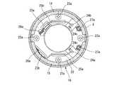
そして、前記回転検出機構51は、電磁誘導形の回転センサであって、図1及び図6に示すように、前記モータ出力軸13の前端内周に一体的に設けられた被検出部である磁性ロータ52と、前記カバー本体3aの第1栓体29の外周側に埋設状態に配置された検出部である2つの第1、第2検出器53、54と、から構成されている。 The
したがって、前記回転検出機構51は、前記一対のスリップリング48a、48bと第1ブラシ23a,23bの摺接位置及びコミュテータ20と第2ブラシ24a、24bの摺接位置よりも内周側に配置されている。 Therefore, the
前記磁性ロータ52は、内周の円周方向のほぼ等間隔位置に軸心方向へ突出した6つのパルス発生歯であるターゲット52a〜52fを有している。 The
一方、前記第1、第2検出器53、54は、内部にヨークと磁束変化を検出する検出コイルを備え、前記磁性ロータ52の回転に伴って各ターゲット52a〜52fが通過する際における磁束変化を検出コイルが検出して図7に示すパルス信号をそれぞれ出力するようになっている。 On the other hand, the first and
前記各ターゲット52a〜52fは、第1、第2検出器53,54で発生するパルス信号P1,P2のHi、Loの幅Wがそれぞれ同一幅となるように周方向へ等間隔に配置されている。 The
前記第1検出器53は、図6に示すように、モータ出力軸13の軸心からの垂線Q上に配置されているのに対して、第2検出器54は、前記垂線Q上のモータ出力軸13の軸心から円周方向へ所定角度θずれた位置に配置されている。この特異な配置によって、図7に示すように、両検出器53、54の第1,第2パルス信号P1,P2は、第1検出器53の第1パルス信号P1のHi信号に第2検出器54の第2パルス信号P2のHi信号がオーバラップすると共に、検出周期が1/4となるように設定されている。 As shown in FIG. 6, the
つまり、図7に示す第1検出器53の第1パルス信号P1における最初のHi信号の上りエッジeから次のHi信号の上りエッジe’までの検出周期を1周期とすると、この1周期の範囲内で、前記第1パルス信号P1と第2パルス信号P2は1/4周期分だけずれた状態になるように配置されている。 That is, assuming that the detection period from the rising edge e of the first Hi signal to the rising edge e ′ of the next Hi signal in the first pulse signal P1 of the
そして、前記コントロールユニット21による検出波形処理方法としては、図8Aに示すように、前記第1、第2検出器53,54の第1、第2パルス信号(Hi,loの組み合わせ)に基づいて、a、b、c、dの領域を判別して電動モータ12の正逆回転の判別を行う。つまり、例えば、b→cの信号を検出した場合にはモータ出力軸13が正回転していると判別し、逆に、b→aの信号を検出した場合にはモータ出力軸13が逆回転していると判別する。 Then, as a detection waveform processing method by the
また、前記各a、b、c、d・・・の信号の出力、つまり切り換わるタイミングにおいてパルスを出力することによって、図8Bに示すように、前記6つのターゲット52a〜52fから24パルスの合成パルス信号が得られる。したがって、前記モータ出力軸13の回転角の分解能が増加する。この図8Bに示すパルス信号出力状態は、タイミングスプロケット1とカムシャフト2の相対回転位相角が一定角度で保持されている状態を示し、図8Cに示すパルス信号出力状態は、前記タイミングスプロケット1に対してカムシャフト2の相対回転位相角が変換中の状態を示している。この相対回転位相の変換中では、図示のように、前記保持中(図8B)の場合に対して高頻度なパルス検出が可能になる。 Further, by outputting a pulse at the timing of switching of the signals a, b, c, d..., That is, switching timing, synthesis of 24 pulses from the six
図8Dは前記カムセンサから出力されたカム角の基準パルス(カムパルス)、図8Eはクランク角センサから出力されたクランク角の基準パルス(クランクパルス)であって、前記2つの検出器53,54からの合成パルスと前記クランクパルスとの相関関係で前記両者1,2の相対回転位相が検出される。 8D is a cam angle reference pulse (cam pulse) output from the cam sensor, and FIG. 8E is a crank angle reference pulse (crank pulse) output from the crank angle sensor. The relative rotational phases of the above-mentioned 1 and 2 are detected by the correlation between the synthesized pulse and the crank pulse.
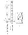
前記タイミングスプロケット1とカムシャフト2の相対回転位相角が一定に保持されている場合と、相対回転位相角を変換している場合を、図9、図10に基づいて具体的に説明する。 The case where the relative rotational phase angle between the timing sprocket 1 and the
まず、前記相対回転位相が一定に保持されている場合は、図9Aに示すように、前記両検出器53,54から出力された合成パルスを検出する毎に、この合成パルスの周波数と、クランク角センサから出力されたクランクパルスの周波数とを比較する。そして、図9Bに示す前記両検出器53,54の合成パルスの周波数とクランクパルスの周波数の相関値を照らし合わせ、両者の周波数相関値が一致していれば、前記相対回転位相角が一定角度に保持された状態にあると検出できる。 First, when the relative rotational phase is kept constant, as shown in FIG. 9A, every time the combined pulse output from the
なお、図中、矢印Zはクランクパルスとカムパルスとの検出タイミングであって、通常の機関中回転域から高回転域においてピックアップされて前記両者1,2の相対回転角(位相変換角)を検出するようになっている。 In the figure, the arrow Z indicates the detection timing of the crank pulse and the cam pulse, and the relative rotation angle (phase conversion angle) of the both 1 and 2 is detected by being picked up from the normal engine rotation range to the high rotation range. It is supposed to be.
次に、前記相対回転位相が変換中の場合は、図10Aに示すように、クランクパルスは変化なく一定に出力されているが、前記両検出器53,54から出力された合成パルス信号は、前記モータ出力軸13の回転速度が大きくなることから前記保持制御の場合に比較して高頻度でかつ細かに出力される。 Next, when the relative rotational phase is being converted, as shown in FIG. 10A, the crank pulse is output without change, but the combined pulse signal output from both
そして、図10Bに示すように、クランクパルス周波数F1に対して前記合成パルスの周波数F2が変化した量を前記相対回転位相角に換算することによって位相変換角Dを検出することができる。すなわち、クランクパルス周波数F1に対して合成パルス周波数F2が高くなる場合(三角山F2A)は、位相変換角Dが進角側に変化したことが検出でき、例えばこの状態からクランクパルス周波数F1に対して一定の場合(平行F2H)はその進角状態が保持されていることが検出できる。さらにこの保持状態からクランクパルス周波数F1に対して合成パルス周波数F2が低くなる場合(逆三角山F2B)は、位相変換角Dが遅角側に変化したことを検出できる。つまり、クランクパルス周波数F1に対して合成パルス周波数F2が変化した量を位相変換角Dに換算することによって、該位相変換角Dを検出するのである。 Then, as shown in FIG. 10B, the phase conversion angle D can be detected by converting the amount of change of the composite pulse frequency F2 with respect to the crank pulse frequency F1 into the relative rotational phase angle. That is, when the composite pulse frequency F2 is higher than the crank pulse frequency F1 (triangular mountain F2A), it can be detected that the phase conversion angle D has changed to the advance side. If the distance is constant (parallel F2H), it can be detected that the advance angle state is maintained. Furthermore, when the composite pulse frequency F2 becomes lower than the crank pulse frequency F1 from this held state (inverted triangular mountain F2B), it can be detected that the phase conversion angle D has changed to the retard side. That is, the phase conversion angle D is detected by converting the amount of change of the composite pulse frequency F2 with respect to the crank pulse frequency F1 into the phase conversion angle D.
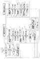
図11は機関運転時と停止時における前記コントロールユニット21による位相変換角Dの検出方法を示すフローチャート図である。
〔機関低回転時の検出方法〕
ステップ1では、機関のクランキング後(始動後)の運転中か否かを判別し、運転中であると判別した場合はステップ2に移行し、このステップ2では、前記クランク角センサからクランクパルスの基準位置を検出する。FIG. 11 is a flowchart showing a method of detecting the phase conversion angle D by the
[Detection method at low engine speed]
In step 1, it is determined whether or not the engine is in operation after cranking (after start-up). If it is determined that the engine is in operation, the process proceeds to step 2. The reference position is detected.
ステップ3では、前記カム角センサによってカムパルスが検出されたか否かを判別し、カムパルスが検出されたと判別した場合は、ステップ4に移行する。このステップ4では、前記クランクパルスとカムパルスに基づく一般的な検出方法によって前記位相変換角Dを検出すると共に、これを更新してリターンする。斯かるステップ1〜4までの検出処理は、機関の中回転域から高回転域の範囲において行われる。 In
前記ステップ3でカムパルスが検出されないと判別した場合は、現在の機関運転状態がクランキング時または所定の低回転域であるとして、ステップ5に移行する。ここでは、この検出ルーチンが開始される直前に予め前記一般的な検出方法で検出されていた位相変換角D1を初期値として記憶する。 If it is determined in
ステップ6では、前記クランクパルス信号から図10Bに示すクランクパルス周波数F1を検出し、ステップ7では、前記第1検出器53から出力されたパルス信号を検出し、さらにステップ8では前記第2検出器54から出力されたパルス信号を検出する。 In step 6, the crank pulse frequency F1 shown in FIG. 10B is detected from the crank pulse signal, in
ステップ9では、図8Aに記載したように、前記第1、第2検出器53,54の両パルス信号から電動モータ12の回転方向を判別する。 In step 9, as described in FIG. 8A, the rotational direction of the
次に、ステップ10で前記両検出器53,54の両パルス信号から合成パルス信号を作成し、ステップ11で図10Bに示した合成パルス周波数F2(電動モータ12のパルス周波数)を算出する。 Next, in
ステップ12では、前記クランクパルス周波数F1と合成パルス周波数F2の相関値が一致したか否かを判別する。この「一致」は完全一致でなくともほぼ一致していれば一致したと認識する。 In
ここで相関値が一致したと判別した場合は、ステップ13に移行し、ここでは、位相変換角Dが一定の角度に保持中であるとして該位相変換角Dを更新せずにステップ1にリターンする。 If it is determined that the correlation values match, the process proceeds to step 13 where the phase conversion angle D is maintained at a constant angle and the process returns to step 1 without updating the phase conversion angle D. To do.
前記ステップ12でクランクパルス周波数F1と合成パルス周波数F2の相関値が一致していないと判別した場合は、ステップ14に移行し、ここでは、位相変換角Dを変換中であると判断し、クランクパルス周波数F1との相関係数からずれた合成パルス周波数F2の変化量を位相角補正値(補完値)Sとして算出する。 If it is determined in
次に、ステップ15では、前記ステップ5で記憶しておいた初期の位相変換角D1に前記位相角補正値Sを加算して現在の位相変換角Dを算出し、これを更新して出力する。 Next, in
なお、本実施形態では、前記合成パルス信号を用いてクランキング直後から低回転域までの位相変換角を求めるようになっているが、これらを通常の機関中回転域や高回転域の検出方法として用いることも可能である。
〔機関停止時の検出方法〕
次に、ステップ16以下では、機関停止時における検出方法を示している。前記ステップ1において機関の停止中であると判別した場合は、ステップ16に移行する。In the present embodiment, the phase conversion angle from immediately after cranking to the low engine speed range is obtained using the composite pulse signal. Can also be used.
[Detection method when the engine is stopped]
Next, steps 16 and thereafter show a detection method when the engine is stopped. If it is determined in step 1 that the engine is stopped, the process proceeds to step 16.
このステップ16では、機関停止直前に検出した相対回転位相角D2、つまり、イグニッションスイッチをオフした後に、惰性で回転したクランクシャフトのクランク角センサと前記カム角センサの各情報信号から算出した相対回転位相角D2をメモリーに記憶しておく。 In
ステップ17では前記第1検出器53から出力されたパルス信号を検出し、さらにステップ18では前記第2検出器54から出力されたパルス信号を検出する。 In
ステップ19では、図8Aに記載したように、前記第1、第2検出器53,54の両パルス信号から電動モータ12(モータ回転軸13)の回転方向を判別する。 In
次に、ステップ20で前記両検出器53,54の両パルス信号から合成パルス信号を作成する。 Next, in
ステップ21では、前記両検出器53,54の合成パルスのカウント数と前記検出されたモータ回転軸13の回転方向の値から、進角側あるいは遅角側の変換方向と位相変換角の変化量(補正値)Dxを算出する。ここでは、通常、機関温度に応じて良好な再始動性を確保するために設定された位相変換角であって、本実施形態では、再始動時の機関温度が所定温度よりも高い場合に対応している。この場合は、最進角側と最遅角側の中間位置から遅角側へ所定角度の位相変換角となるように設定されている。 In
なお、この位相変換角Dは、任意に設定することが可能であり、例えば、暖機始動時には、デコンプ効果(低圧縮効果)によって自己着火現象を回避するために、前記位相変換角Dを最遅角側に設定することも可能であり、また、機関運転状態に応じて最進角と最遅角の中間位置となるように設定することも可能である。 The phase conversion angle D can be arbitrarily set. For example, at the start of warm-up, the phase conversion angle D is maximized in order to avoid a self-ignition phenomenon by a decompression effect (low compression effect). It is also possible to set to the retard side, and it is also possible to set the intermediate position between the most advanced angle and the most retarded angle according to the engine operating state.
次に、ステップ22において、前記ステップ16で予め記憶しておいた相対回転位相角D2に、ステップ21で算出した位相変換角の補正値Dxを加算した値を現在の位相変換角Dとして更新してこれを出力した後、リターンする。 Next, in
以上のように、本実施形態は、ブラシ付きの電動モータ12を用いていることから、前記電動モータ12のハウジング5のみをタイミングスプロケット1と一緒に回転させるだけで、ロータ自体は常時回転させることがないので、前記従来技術に比較して機関の消費エネルギーを低減させることが可能になる。 As described above, since this embodiment uses the
また、タイミングスプロケット1とカムシャフト2の相対回転位相角Dを、クランク角センサとカム角センサの一般的な検出の他に、前記クランク角センサと回転検出機構51の第1、第2検出器53、54を用いて現在の位相変換角Dを高頻度で検出することができるため、より高精度な検出が可能になる。 The relative rotational phase angle D between the timing sprocket 1 and the
特に、機関クランキング時の極低回転域や低回転域では、前記一般的な検出方法では検出頻度が少ないことから検出精度が低くなるが、本実施形態では、前記回転検出機構51を機関クランキング時の極低回転域から低回転域において用いるようにしたため、かかる回転領域での高頻度な検出によって位相変換角Dの高精度な検出が可能になる。この結果、吸気弁のバルブタイミングの制御の安定化と制御応答性の向上が図れる。 In particular, in the extremely low rotation range and low rotation range during engine cranking, the detection accuracy is low because the detection frequency is low in the general detection method. However, in the present embodiment, the
しかも、前記回転検出機構51は、前記一対のスリップリング48a、48bと各ブラシ23a,23bの配設位置よりも内周側に配置されていることから、機関運転時に前記各ブラシ23a、23bとスリップリング48a、48bの摺動によって発生する種々の影響を回避することが可能になる。 In addition, since the
すなわち、前記回転検出機構51の各検出器53,54を、各ブラシ23a、23bや各スリップリング48a、48bの外周側に配置した場合は、各ブラシ23a、23bと各スリップリング48a、48bの内周との摺動によって発生する摩耗粉がハウジング5の回転遠心力によって飛散して各検出器53,54に付着して検出精度が低下するおそれがある。しかし、本実施形態では、各検出器53,54を、各ブラシ23a、23bと各スリップリング48a、48bの内周側に配置したことから、前記摩耗粉が各スリップリング48a、48bの外周方向へ飛散するため、該摩耗粉による回転検出機構51の検出精度の低下を抑制できる。 That is, when the
また、前記摩耗粉による電動モータ12が発生する磁界への影響や前記各ブラシ23a、23bとスリップリング48a、48bとの摺動部で発生する電磁ノイズの影響を抑制することが可能になる。 In addition, it is possible to suppress the influence of the abrasion powder on the magnetic field generated by the
また、前記回転検出機構51の磁性ロータ52を、モータ出力軸13と一体に形成したことから、構造の簡素化が図れ、組付作業や製造作業が容易になってコストの低減化が図れる。 Further, since the
さらに、前記カバー部材3を非磁性の合成樹脂材によって形成したことから、前記第1、第2検出器53,54をカバー部材3内に埋設することができるため、装置の軸方向の長さを短尺化できると共に、この点でもコストの低減化が図れる。 Further, since the
しかも、前記カバー部材3を合成樹脂材によって形成したことによって機関の全体の軽量化が図れると共に、前記各スリップリング48a、48bやコネクタ端子49aなどを一体的に設けることができるので、これらの製造作業が容易になる。 Moreover, the overall weight of the engine can be reduced by forming the
本実施形態は、前記減速機構8のニードルベアリング28と第1ボールベアリング33を径方向のほぼ同一位置に配置し、特に、ニードルベアリング28と同じ径方向位置に前記環状部材19とローラ34を配置したことから、装置の軸方向の長さを十分に短くすることが可能になる。この結果、装置の小型化と軽量化が図れる。 In this embodiment, the
しかも、前記減速機構8の構造が簡素化されるため、製造作業や組立作業が容易になり、これらのコストを十分に低減することができる。 In addition, since the structure of the
また、前記環状部材19の内歯19aの歯面とローラ34が噛み合う位置の径方向内周側に前記ニードルベアリング28が配置されていることから、環状部材19側から径方向内側へ作用する大きな荷重を前記ニードルベアリング28によって受けることができる。このため、前記荷重による曲げモーメントが前記モータ出力軸13に殆ど作用しない。したがって、モータ出力軸13の常時スムーズな回転が得られる。 Further, since the
さらに、前記減速機構8内には、オイル供給孔46aから潤滑油が強制的に供給されることから、減速機構8の各部の潤滑性が向上すると共に、内歯19aとローラ34との間や、ニードルベアリング28、第1ボールベアリング33に潤滑油が供給されて、各ローラ、28b、34や各ボールとの間の潤滑性も向上して減速機構8による常時滑らかな位相変換が行われることは勿論のこと、この潤滑油が緩衝機能を発揮するため、前記打音の発生をより効果的に抑制することが可能になる。 Further, since the lubricating oil is forcibly supplied into the
特に、機関の駆動中はオイルポンプから圧送された潤滑油が前記潤滑油供給手段を介して常時供給されて浸漬された状態になるため、前記各転動体の油膜切れの発生が抑制できる。これにより、電動モータ12の初期駆動負荷を十分に低減でき、バルブタイミングの制御応答性の向上と消費エネルギーの減少化が図れる。 In particular, during the driving of the engine, the lubricating oil pumped from the oil pump is constantly supplied and immersed through the lubricating oil supply means, so that the occurrence of oil film breakage of each rolling element can be suppressed. Thereby, the initial driving load of the
また、前記減速機構8内部から前記各オイル排出孔を介して外部に排出された潤滑油は、遠心力によって前記第2ボールベアリング43に付着すると共に、タイミングスプロケット1の各ギア部1bに付着して、これらの部位を効率良く潤滑する。 The lubricating oil discharged from the inside of the
さらに、前記モータ出力軸13と偏心軸部30を、ニードルベアリング28と第3ボールベアリング35を介してカムボルト10に支持したため、別途支持軸を設ける必要がなくなり、部品点数の削減が図れると共に、カムシャフト2に軸方向から直接結合されているので、カムシャフト2に対して径方向の倒れが抑制されて高い同軸性が得られる。 Further, since the
また、ハウジング5によって減速機構8と電動モータ12との一体化が図れると共に、スプロケット本体1aを介してタイミングスプロケット1との一体化も図れることから、これら各構成部品全体のユニット化が図れる。したがって、装置の軸方向の他に径方向の小型化が図れると共に、製品管理が容易になる。 In addition, the
また、前記第2オイルシール32は、前記モータ出力軸13に摩擦抵抗を付与することから、バルブスプリングのばね力などによって前記カムシャフト2に発生する交番トルクを吸収して電動モータ12の負荷を抑制することができる。 Further, since the
また、前記モータ出力軸13と偏心軸部30とを一体化したことによって、分割した場合に比較して部品点数の削減が図れると共に、組付、製造作業が容易になり、この点でもコストの低減化が図れる。 Further, by integrating the
本発明は、前記実施形態の構成に限定されるものではなく、例えば、前記磁性ローラ52をモータ出力軸13と別体に形成することも可能であり、また、各ターゲット52a〜52fの数をさらに増加するか、あるいは減少することも可能である。
前記実施形態から把握される前記請求項以外の発明の技術的思想について以下に説明する。
〔請求項a〕請求項1に記載の内燃機関のバルブタイミング制御装置において、前記被検出部を、前記モータ出力軸の先端側に設ける一方、前記検出部を前記固定部材に設けたことを特徴とする内燃機関のバルブタイミング制御装置。
〔請求項b〕請求項aに記載の内燃機関のバルブタイミング制御装置において、前記被検出部を、前記モータ出力軸の先端に設けたことを特徴とする内燃機関のバルブタイミング制御装置。
〔請求項c〕請求項1に記載の内燃機関のバルブタイミング制御装置において、前記被検出部は、周方向のほぼ等間隔位置に複数突設されてなるパルス発生歯によって構成されている一方、前記検出部は、磁束を計測できる磁気センサによって構成されていることを特徴とする内燃機関のバルブタイミング制御装置。
〔請求項d〕請求項1に記載の内燃機関のバルブタイミング制御装置において、前記駆動回転体に対する従動回転体の相対回転位相は所定角度範囲内に規制されていると共に、機関の停止時には、前記駆動回転体に対する従動回転体の相対回転位相を最遅角側に制御し、機関の再始動のクランキング時には、少なくとも機関温度状態に応じて前記電動モータを駆動させて所望の相対回転位相に制御することを特徴とする内燃機関のバルブタイミング制御装置。
〔請求項e〕請求項1に記載の内燃機関のバルブタイミング制御装置において、機関の停止時に、前記駆動回転体に対する従動回転体の相対回転角度を制御回路のメモリーに記憶しておき、
機関の再始動のクランキング時に、機関が始動可能なバルブタイミングとなるように前記電動モータを駆動させることを特徴とする内燃機関のバルブタイミング制御装置。
〔請求項f〕請求項1に記載の内燃機関のバルブタイミング制御装置において、機関の暖機始動のクランキング時に、前記電動モータを前記カムシャフトの回転方向と逆回転させることによって駆動回転体と従動回転体の相対回転位相を遅角側に制御したことを特徴とする内燃機関のバルブタイミング制御装置。
〔請求項g〕請求項1に記載の内燃機関のバルブタイミング制御装置において、前記コイルを前記ロータに設けると共に、コミュテータと該コミュテータに当接する通電切換用ブラシによって前記コイルへの通電状態を切り換えることを特徴とする内燃機関のバルブタイミング制御装置。
〔請求項h〕請求項gに記載の内燃機関のバルブタイミング制御装置において、前記ステータは、異なる磁極が交互に形成された永久磁石によって構成されていることを特徴とする内燃機関のバルブタイミング制御装置。
〔請求項i〕請求項gに記載の内燃機関のバルブタイミング制御装置において、前記被検出部と検出部を、前記コミュテータと通電切換用ブラシの当接箇所より内周側に設けたことを特徴とする内燃機関のバルブタイミング制御装置。
〔請求項j〕請求項1に記載の内燃機関のバルブタイミング制御装置において、前記固定部材は、前記駆動回転体の少なくとも一部を覆うように配置されたカバー部材によって構成され、該カバー部材が内燃機関のシリンダヘッドに固定されていることを特徴とする内燃機関のバルブタイミング制御装置。
〔請求項k〕請求項jに記載の内燃機関のバルブタイミング制御装置において、前記カバー部材は、非磁性体によって形成されていることを特徴とする内燃機関のバルブタイミング制御装置。
〔請求項l〕請求項jに記載の内燃機関のバルブタイミング制御装置において、前記検出部は、前記カバー部材に一体的に固定されていることを特徴とする内燃機関のバルブタイミング制御装置。The present invention is not limited to the configuration of the above-described embodiment. For example, the
The technical ideas of the invention other than the claims ascertained from the embodiment will be described below.
[Claim a] The valve timing control apparatus for an internal combustion engine according to claim 1, wherein the detected portion is provided on a front end side of the motor output shaft, and the detecting portion is provided on the fixing member. A valve timing control device for an internal combustion engine.
[B] A valve timing control device for an internal combustion engine according to claim a, wherein the detected portion is provided at a tip of the motor output shaft.
[Claim c] In the valve timing control apparatus for an internal combustion engine according to claim 1, the detected portion is constituted by a plurality of pulse generating teeth provided in a plurality of positions at substantially equal intervals in the circumferential direction. The valve timing control device for an internal combustion engine, wherein the detection unit is configured by a magnetic sensor capable of measuring magnetic flux.
[Claim d] In the valve timing control apparatus for an internal combustion engine according to claim 1, the relative rotational phase of the driven rotor relative to the drive rotor is regulated within a predetermined angle range, and when the engine is stopped, The relative rotation phase of the driven rotor relative to the drive rotor is controlled to the most retarded angle side, and at the time of engine restart cranking, the electric motor is driven at least according to the engine temperature state to control the desired relative rotation phase. A valve timing control device for an internal combustion engine.
[Claim e] In the valve timing control apparatus for an internal combustion engine according to claim 1, when the engine is stopped, the relative rotation angle of the driven rotor with respect to the drive rotor is stored in the memory of the control circuit,
A valve timing control device for an internal combustion engine, wherein the electric motor is driven so as to have a valve timing at which the engine can be started during cranking of restarting the engine.
[Claim f] The valve timing control apparatus for an internal combustion engine according to claim 1, wherein the electric motor is rotated reversely to the rotational direction of the camshaft when cranking for warm-up of the engine. A valve timing control device for an internal combustion engine, wherein the relative rotational phase of the driven rotor is controlled to the retard side.
[Claim g] In the valve timing control apparatus for an internal combustion engine according to claim 1, the coil is provided in the rotor, and the energization state of the coil is switched by a commutator and an energization switching brush in contact with the commutator. An internal combustion engine valve timing control device.
[Claim h] The valve timing control device for an internal combustion engine according to claim g, wherein the stator is constituted by a permanent magnet in which different magnetic poles are alternately formed. apparatus.
[Claim i] The valve timing control apparatus for an internal combustion engine according to claim g, wherein the detected portion and the detecting portion are provided on an inner peripheral side from a contact portion between the commutator and the energization switching brush. A valve timing control device for an internal combustion engine.
[Claim j] In the valve timing control apparatus for an internal combustion engine according to claim 1, the fixing member is constituted by a cover member disposed so as to cover at least a part of the drive rotating body, and the cover member includes A valve timing control device for an internal combustion engine, being fixed to a cylinder head of the internal combustion engine.
[Claim k] The valve timing control device for an internal combustion engine according to claim j, wherein the cover member is made of a non-magnetic material.
[Claim 1] The valve timing control apparatus for an internal combustion engine according to claim j, wherein the detection unit is integrally fixed to the cover member.
1…タイミングスプロケット(駆動回転体)
2…カムシャフト
3…カバー部材
3a…カバー本体
4…位相変更機構
5…ハウジング
6…プレート
8…減速機構
9…従動部材(従動回転体)
10…カムボルト
12…電動モータ
13…モータ出力軸
17…鉄心ロータ
18…電磁コイル
19…環状部材
19a…内歯
23a、23b…第1ブラシ(給電用ブラシ)
24a、24b…第2ブラシ(通電切換用ブラシ)
28…ニードルベアリング
30…偏心軸部
32…第2オイルシール
33…第1ボールベアリング
34…ローラ
35…第3ボールベアリング
43…第2ボールベアリング
48a、48b…スリップリング
51…回転検出機構
52…磁性ローラ(被検出部)
52a〜52f…ターゲット(パルス発生歯)
53・54…第1、第2検出器(検出部)1. Timing sprocket (rotating drive)
2 ...
DESCRIPTION OF
24a, 24b ... second brush (energization switching brush)
28 ... Needle bearing 30 ...
52a-52f ... Target (pulse generation tooth)
53.54. First and second detectors (detection units)
Claims (3)
Translated fromJapaneseカムシャフトに固定された従動回転体と、
前記駆動回転体に固定されたステータと、該ステータに対して相対回転するロータと、前記ステータ及びロータの少なくとも一方に設けられ、通電することによって前記ステータに対して前記ロータを回転させるコイルと、前記ロータに固定されたモータ出力軸と、を備えた電動モータと、
前記モータ出力軸の回転を減速して前記従動回転体に伝達する減速機構と、
前記駆動回転体または該駆動回転体と対向する固定部材のいずれか一方に設けられ、前記コイルに給電するスリップリングと、
前記駆動回転体と固定部材のいずれか他方に設けられて、前記スリップリングに当接する給電用ブラシと、
前記モータ出力軸の先端側に設けられ、前記スリップリングと給電用ブラシの当接箇所より内周側に配置された被検出部と、
前記固定部材に設けられ、前記被検出部の位置を検出して前記モータ出力軸の回転位置を検出する検出部と、を備えたことを特徴とする内燃機関のバルブタイミング制御装置。A driving rotating body to which rotational force is transmitted from the crankshaft;
A driven rotating body fixed to the camshaft;
A stator fixed to the drive rotor, a rotor that rotates relative to the stator, and a coil that is provided in at least one of the stator and the rotor and rotates the rotor relative to the stator by energization; An electric motor provided with a motor output shaft fixed to the rotor;
A speed reduction mechanism for decelerating the rotation of the motor output shaft and transmitting it to the driven rotor;
A slip ring that is provided on either the drive rotator or a fixed member facing the drive rotator and that feeds power to the coil;
A power supply brush that is provided on the other side of the drive rotator and the fixed member and abuts against the slip ring;
A detected portion providedon the tipside of the motor output shaft and disposed on the inner peripheral side from the contact portion of the slip ring and the power supply brush;
It providedin frontSymbol solid toughmaterial, the valve timing control apparatus for an internal combustion engine characterized by comprising a detecting section for detecting a rotational position of the motor output shaft to detect the position of the detected portion.
カムシャフトに固定された従動回転体と、
前記駆動回転体に固定されたステータと、該ステータに対して相対回転するロータと、該ロータと一体的に回転するように設けられ、通電することによって周方向に異なる磁極を形成する複数のコイルと、該コイルへの通電状態を切り換えるコミュテータと、前記駆動回転体に設けられ、前記コミュテータに当接する通電切換用ブラシと、前記ロータに固定されたモータ出力軸と、を備え、前記通電切換用ブラシとコミュテータを介して前記コイルに通電することによって前記モータ出力軸を回転させる電動モータと、
前記モータ出力軸の回転を減速して前記従動回転体に伝達する減速機構と、
前記モータ出力軸の先端側に設けられ、前記コミュテータと通電切換用ブラシの当接箇所より内周側に配置された被検出部と、
前記固定部材に設けられ、前記被検出部の位置を検出して前記モータ出力軸の回転位置を検出する検出部と、を備えたことを特徴とする内燃機関のバルブタイミング制御装置。A driving rotating body to which rotational force is transmitted from the crankshaft;
A driven rotating body fixed to the camshaft;
A stator fixed to the drive rotating body, a rotor that rotates relative to the stator, and a plurality of coils that are provided so as to rotate integrally with the rotor and that form different magnetic poles in the circumferential direction when energized. A commutator for switching the energization state of the coil, an energization switching brush provided on the drive rotating body and in contact with the commutator, and a motor output shaft fixed to the rotor. An electric motor that rotates the motor output shaft by energizing the coil through a brush and a commutator;
A speed reduction mechanism for decelerating the rotation of the motor output shaft and transmitting it to the driven rotor;
A detected portion thatis providedon the tipside of the motor output shaft and is arranged on the inner peripheral side from the contact point between the commutator and the energization switching brush;
BeforeSL providedfixed member, the valve timing control apparatus for an internal combustion engine characterized by comprising a detecting section for detecting a rotational position of the motor output shaft to detect the position of the detected portion.
カムシャフトに固定された従動回転体と、
前記駆動回転体に固定されたステータと、該ステータに対して相対回転するロータと、該ロータと一体的に回転するように設けられ、通電することによって周方向に異なる磁極を形成する複数のコイルと、該コイルへの通電状態を切り換えるコミュテータと、前記駆動回転体に設けられ、前記コミュテータに当接する通電切換用ブラシと、前記ロータに固定されたモータ出力軸と、を備え、前記通電切換用ブラシとコミュテータを介して前記コイルに通電することによって前記モータ出力軸を回転させる電動モータと、
前記モータ出力軸の回転を減速して前記従動回転体に伝達する減速機構と、
前記駆動回転体または該駆動回転体と対向する固定部材のいずれか一方に設けられ、前記通電切換用ブラシに給電するスリップリングと、
前記駆動回転体と固定部材のいずれか他方に設けられて、前記スリップリングに当接する給電用ブラシと、
前記スリップリングと給電用ブラシの当接箇所及び前記コミュテータと通電切換用ブラシの当接箇所よりも内周側で、前記モータ出力軸の回転位置を、前記固定部材に設けられた検出部によって検出することを特徴とする内燃機関のバルブタイミング制御装置。A driving rotating body to which rotational force is transmitted from the crankshaft;
A driven rotating body fixed to the camshaft;
A stator fixed to the drive rotating body, a rotor that rotates relative to the stator, and a plurality of coils that are provided so as to rotate integrally with the rotor and that form different magnetic poles in the circumferential direction when energized. A commutator for switching the energization state of the coil, an energization switching brush provided on the drive rotating body and in contact with the commutator, and a motor output shaft fixed to the rotor. An electric motor that rotates the motor output shaft by energizing the coil through a brush and a commutator;
A speed reduction mechanism for decelerating the rotation of the motor output shaft and transmitting it to the driven rotor;
A slip ring that is provided on either the drive rotator or a fixed member facing the drive rotator, and supplies power to the energization switching brush;
A power supply brush that is provided on the other side of the drive rotator and the fixed member and abuts against the slip ring;
The rotation position of the motor output shaftis detectedby a detection unit provided on the fixing member, on the inner peripheral side of the contact point between the slip ring and the power supply brush and the contact point between the commutator and the energization switching brush. A valve timing control device for an internal combustion engine.
Priority Applications (3)
| Application Number | Priority Date | Filing Date | Title |
|---|---|---|---|
| JP2010096581AJP5208154B2 (en) | 2010-04-20 | 2010-04-20 | Valve timing control device for internal combustion engine |
| CN201110066339.8ACN102235194B (en) | 2010-04-20 | 2011-03-18 | Valve-timing control apparatus for internal combustion engine |
| US13/078,016US8899197B2 (en) | 2010-04-20 | 2011-04-01 | Valve-timing control apparatus for internal combustion engine |
Applications Claiming Priority (1)
| Application Number | Priority Date | Filing Date | Title |
|---|---|---|---|
| JP2010096581AJP5208154B2 (en) | 2010-04-20 | 2010-04-20 | Valve timing control device for internal combustion engine |
Publications (2)
| Publication Number | Publication Date |
|---|---|
| JP2011226372A JP2011226372A (en) | 2011-11-10 |
| JP5208154B2true JP5208154B2 (en) | 2013-06-12 |
Family
ID=44787190
Family Applications (1)
| Application Number | Title | Priority Date | Filing Date |
|---|---|---|---|
| JP2010096581AExpired - Fee RelatedJP5208154B2 (en) | 2010-04-20 | 2010-04-20 | Valve timing control device for internal combustion engine |
Country Status (3)
| Country | Link |
|---|---|
| US (1) | US8899197B2 (en) |
| JP (1) | JP5208154B2 (en) |
| CN (1) | CN102235194B (en) |
Families Citing this family (33)
| Publication number | Priority date | Publication date | Assignee | Title |
|---|---|---|---|---|
| JP5208154B2 (en)* | 2010-04-20 | 2013-06-12 | 日立オートモティブシステムズ株式会社 | Valve timing control device for internal combustion engine |
| JP5530877B2 (en)* | 2010-09-14 | 2014-06-25 | 日立オートモティブシステムズ株式会社 | Valve timing control device for internal combustion engine |
| CN103229398B (en)* | 2010-12-10 | 2016-03-30 | 三菱电机株式会社 | Electric rotating machine |
| JP2013167181A (en)* | 2012-02-15 | 2013-08-29 | Hitachi Automotive Systems Ltd | Valve timing control apparatus for internal combustion engine |
| KR101710251B1 (en)* | 2012-07-12 | 2017-02-24 | 히다치 오토모티브 시스템즈 가부시키가이샤 | Variable valve device for internal combustion engine |
| JP5976505B2 (en)* | 2012-11-07 | 2016-08-23 | 日立オートモティブシステムズ株式会社 | Valve timing control device for internal combustion engine |
| JP5953423B2 (en)* | 2013-03-08 | 2016-07-20 | 本田技研工業株式会社 | Generator / motor unit, power output engine, and vehicle |
| JP6096611B2 (en)* | 2013-07-04 | 2017-03-15 | 日立オートモティブシステムズ株式会社 | Valve timing control device for internal combustion engine and power feeding mechanism used for the valve timing control device |
| WO2015045542A1 (en)* | 2013-09-26 | 2015-04-02 | 日立オートモティブシステムズ株式会社 | Valve timing control device for internal combustion engine |
| KR101490945B1 (en)* | 2013-11-12 | 2015-02-09 | 현대자동차 주식회사 | Continuously variable valve timing device |
| JP6235413B2 (en)* | 2014-06-03 | 2017-11-22 | 日立オートモティブシステムズ株式会社 | Valve timing control device for internal combustion engine |
| JP6236362B2 (en) | 2014-06-30 | 2017-11-22 | 日立オートモティブシステムズ株式会社 | Valve timing control device and variable valve operating device for internal combustion engine |
| JPWO2016009790A1 (en)* | 2014-07-15 | 2017-04-27 | 日立オートモティブシステムズ株式会社 | Variable valve operating device for internal combustion engine |
| JP6174262B2 (en)* | 2014-07-15 | 2017-08-02 | 日立オートモティブシステムズ株式会社 | Variable valve operating device and valve timing control device for internal combustion engine |
| US9708940B2 (en)* | 2014-07-31 | 2017-07-18 | Delphi Technologies, Inc. | Internal combustion engine with a camshaft phaser |
| JP2016048053A (en)* | 2014-08-28 | 2016-04-07 | 日立オートモティブシステムズ株式会社 | Valve timing control device and valve timing control system for internal combustion engine |
| JP6326333B2 (en)* | 2014-09-17 | 2018-05-16 | 日立オートモティブシステムズ株式会社 | Valve timing control device for internal combustion engine |
| JP6263462B2 (en)* | 2014-10-16 | 2018-01-17 | 日立オートモティブシステムズ株式会社 | Valve timing control device for internal combustion engine |
| JP6295181B2 (en) | 2014-11-04 | 2018-03-14 | 日立オートモティブシステムズ株式会社 | Valve timing control device for internal combustion engine |
| JP6283599B2 (en)* | 2014-11-26 | 2018-02-21 | 日立オートモティブシステムズ株式会社 | Valve timing control system for internal combustion engine |
| JP6381785B2 (en)* | 2015-03-30 | 2018-08-29 | 日立オートモティブシステムズ株式会社 | Valve timing control device for internal combustion engine |
| JP6339042B2 (en)* | 2015-04-15 | 2018-06-06 | 日立オートモティブシステムズ株式会社 | Valve timing control device for internal combustion engine |
| US10180088B2 (en) | 2015-05-29 | 2019-01-15 | Borgwarner Inc. | Tapered roller drive for electric VCT phaser |
| JP6488519B2 (en)* | 2015-07-27 | 2019-03-27 | 日立オートモティブシステムズ株式会社 | Actuator of link mechanism for internal combustion engine |
| JPWO2017047254A1 (en)* | 2015-09-15 | 2018-06-28 | 日立オートモティブシステムズ株式会社 | Valve timing control device for internal combustion engine |
| KR101655225B1 (en)* | 2015-12-09 | 2016-09-22 | 현대자동차 주식회사 | Valve timing control device of internal combustion engine |
| JP6542661B2 (en)* | 2015-12-28 | 2019-07-10 | 日立オートモティブシステムズ株式会社 | Valve timing control system for internal combustion engine |
| WO2017150089A1 (en)* | 2016-03-04 | 2017-09-08 | 日立オートモティブシステムズ株式会社 | Internal-combustion engine valve timing control device |
| USD793970S1 (en)* | 2016-04-21 | 2017-08-08 | RB Distribution, Inc. | Magnetic actuator |
| FR3051835B1 (en)* | 2016-05-27 | 2018-05-11 | Sonceboz Automotive Sa | DIRECT SHAFT ELECTRIC CAM SHAFT DEEPER |
| CN105927308A (en)* | 2016-05-31 | 2016-09-07 | 绵阳富临精工机械股份有限公司 | Belt type cam phaser |
| DE102018102880A1 (en)* | 2017-02-16 | 2018-08-16 | Borgwarner Inc. | Method for start-up control of an electric camshaft adjuster |
| JP7366827B2 (en)* | 2020-03-31 | 2023-10-23 | 本田技研工業株式会社 | Detection device and control device |
Family Cites Families (28)
| Publication number | Priority date | Publication date | Assignee | Title |
|---|---|---|---|---|
| JP3535827B2 (en)* | 1997-10-01 | 2004-06-07 | カヤバ工業株式会社 | Electric motor for electric power steering device |
| JP3985305B2 (en)* | 1997-10-07 | 2007-10-03 | マツダ株式会社 | Rotation phase controller |
| US6302073B1 (en)* | 1999-03-23 | 2001-10-16 | Tcg Unitech Aktiengesellschaft | Device for adjusting the phase angle of a camshaft of an internal combustion engine |
| JP3566677B2 (en)* | 2001-08-20 | 2004-09-15 | 三菱電機株式会社 | Rotating electric machine |
| JP3546866B2 (en)* | 2001-08-20 | 2004-07-28 | 三菱電機株式会社 | Starting charging rotary electric machine for vehicles |
| DE10248355A1 (en)* | 2002-10-17 | 2004-04-29 | Ina-Schaeffler Kg | Camshaft adjuster with electric drive |
| JP4097145B2 (en)* | 2003-11-20 | 2008-06-11 | 三菱電機株式会社 | Rotating electric machine for vehicles |
| JP4179192B2 (en)* | 2004-03-08 | 2008-11-12 | 株式会社デンソー | Combustion state detection device for internal combustion engine |
| JP4468033B2 (en)* | 2004-03-22 | 2010-05-26 | アスモ株式会社 | Electric motor for variable valve timing device of vehicle engine |
| JP4327681B2 (en)* | 2004-08-04 | 2009-09-09 | トヨタ自動車株式会社 | Resin cylinder head cover |
| JP2006257958A (en)* | 2005-03-17 | 2006-09-28 | Hitachi Ltd | Cam phase sensor, variable valve timing mechanism control device, and variable valve timing mechanism control method |
| JP4767096B2 (en)* | 2006-06-09 | 2011-09-07 | トヨタ自動車株式会社 | Variable valve timing device |
| JP4957191B2 (en)* | 2006-11-03 | 2012-06-20 | 株式会社デンソー | Motor driver and manufacturing method thereof |
| JP2008141917A (en)* | 2006-12-05 | 2008-06-19 | Mitsuba Corp | Motor |
| JP2009091928A (en)* | 2007-10-05 | 2009-04-30 | Hitachi Ltd | Valve timing control device for internal combustion engine |
| DE102008008117A1 (en)* | 2008-02-08 | 2009-08-13 | Schaeffler Kg | Method for adjusting a camshaft of an internal combustion engine and internal combustion engine with an adjustable camshaft |
| JP5102071B2 (en)* | 2008-03-03 | 2012-12-19 | 日鍛バルブ株式会社 | Phase variable device for automobile engine |
| JP5047356B2 (en)* | 2008-04-23 | 2012-10-10 | 日鍛バルブ株式会社 | Phase variable device for automobile engine |
| JP2009293576A (en)* | 2008-06-09 | 2009-12-17 | Hitachi Automotive Systems Ltd | Valve timing control device of internal combustion engine |
| JP2010223068A (en)* | 2009-03-23 | 2010-10-07 | Hitachi Automotive Systems Ltd | Control device for internal combustion engine |
| JP4760953B2 (en)* | 2009-05-18 | 2011-08-31 | 株式会社デンソー | Valve timing adjustment device |
| EP2295741A1 (en)* | 2009-08-31 | 2011-03-16 | Delphi Technologies, Inc. | Valve train with variable cam phaser |
| US20110100312A1 (en)* | 2009-11-02 | 2011-05-05 | Denso Corporation | Control system for variable valve timing apparatus |
| EP2360358A1 (en)* | 2010-02-24 | 2011-08-24 | Delphi Technologies, Inc. | Electrical camshaft phaser with energy recovery |
| JP5208154B2 (en)* | 2010-04-20 | 2013-06-12 | 日立オートモティブシステムズ株式会社 | Valve timing control device for internal combustion engine |
| US8800513B2 (en)* | 2011-05-20 | 2014-08-12 | Delphi Technologies, Inc. | Axially compact coupling for a camshaft phaser actuated by electric motor |
| US8726865B2 (en)* | 2011-06-08 | 2014-05-20 | Delphi Technologies, Inc. | Harmonic drive camshaft phaser using oil for lubrication |
| US8677961B2 (en)* | 2011-07-18 | 2014-03-25 | Delphi Technologies, Inc. | Harmonic drive camshaft phaser with lock pin for selectivley preventing a change in phase relationship |
- 2010
- 2010-04-20JPJP2010096581Apatent/JP5208154B2/ennot_activeExpired - Fee Related
- 2011
- 2011-03-18CNCN201110066339.8Apatent/CN102235194B/ennot_activeExpired - Fee Related
- 2011-04-01USUS13/078,016patent/US8899197B2/ennot_activeExpired - Fee Related
Also Published As
| Publication number | Publication date |
|---|---|
| US8899197B2 (en) | 2014-12-02 |
| CN102235194B (en) | 2015-07-01 |
| CN102235194A (en) | 2011-11-09 |
| JP2011226372A (en) | 2011-11-10 |
| US20110253085A1 (en) | 2011-10-20 |
Similar Documents
| Publication | Publication Date | Title |
|---|---|---|
| JP5208154B2 (en) | Valve timing control device for internal combustion engine | |
| JP4987031B2 (en) | Valve timing control device for internal combustion engine | |
| JP5538053B2 (en) | Variable valve operating device for internal combustion engine | |
| JP5654950B2 (en) | Valve timing control device for internal combustion engine | |
| JP5978080B2 (en) | Valve timing control device for internal combustion engine and controller for the valve timing control device | |
| JP5379669B2 (en) | Variable valve operating device for internal combustion engine | |
| JP6295181B2 (en) | Valve timing control device for internal combustion engine | |
| JP5411066B2 (en) | Variable valve operating device for internal combustion engine | |
| JP6236362B2 (en) | Valve timing control device and variable valve operating device for internal combustion engine | |
| US20130206087A1 (en) | Valve timing control apparatus for internal combustion engine | |
| JP5978111B2 (en) | Valve timing control device for internal combustion engine | |
| US9115611B2 (en) | Variable valve operating apparatus for internal combustion engine | |
| JP5823769B2 (en) | Valve timing control device for internal combustion engine | |
| JP5719008B2 (en) | Variable valve operating device for internal combustion engine | |
| JP5693312B2 (en) | Valve timing control device for internal combustion engine | |
| JP5530877B2 (en) | Valve timing control device for internal combustion engine | |
| JP6263462B2 (en) | Valve timing control device for internal combustion engine | |
| JP5687727B2 (en) | Variable valve operating device for internal combustion engine | |
| JP5718764B2 (en) | Valve timing control device for internal combustion engine | |
| JP6311044B2 (en) | Variable valve operating device for internal combustion engine | |
| JP2022018675A (en) | Valve timing control device and roller reduction gear of internal combustion engine | |
| JP7038000B2 (en) | Internal combustion engine valve timing controller | |
| JP2017120183A (en) | Valve timing control device for internal combustion engine | |
| JP2014214723A (en) | Variable valve device of internal combustion engine | |
| JP2019049207A (en) | Valve timing control device of internal combustion engine |
Legal Events
| Date | Code | Title | Description |
|---|---|---|---|
| A521 | Request for written amendment filed | Free format text:JAPANESE INTERMEDIATE CODE: A523 Effective date:20120221 | |
| A621 | Written request for application examination | Free format text:JAPANESE INTERMEDIATE CODE: A621 Effective date:20120221 | |
| A977 | Report on retrieval | Free format text:JAPANESE INTERMEDIATE CODE: A971007 Effective date:20120611 | |
| A131 | Notification of reasons for refusal | Free format text:JAPANESE INTERMEDIATE CODE: A131 Effective date:20120619 | |
| A521 | Request for written amendment filed | Free format text:JAPANESE INTERMEDIATE CODE: A523 Effective date:20120810 | |
| TRDD | Decision of grant or rejection written | ||
| A01 | Written decision to grant a patent or to grant a registration (utility model) | Free format text:JAPANESE INTERMEDIATE CODE: A01 Effective date:20130205 | |
| A61 | First payment of annual fees (during grant procedure) | Free format text:JAPANESE INTERMEDIATE CODE: A61 Effective date:20130219 | |
| FPAY | Renewal fee payment (event date is renewal date of database) | Free format text:PAYMENT UNTIL: 20160301 Year of fee payment:3 | |
| R150 | Certificate of patent or registration of utility model | Ref document number:5208154 Country of ref document:JP Free format text:JAPANESE INTERMEDIATE CODE: R150 Free format text:JAPANESE INTERMEDIATE CODE: R150 | |
| R250 | Receipt of annual fees | Free format text:JAPANESE INTERMEDIATE CODE: R250 | |
| R250 | Receipt of annual fees | Free format text:JAPANESE INTERMEDIATE CODE: R250 | |
| R250 | Receipt of annual fees | Free format text:JAPANESE INTERMEDIATE CODE: R250 | |
| R250 | Receipt of annual fees | Free format text:JAPANESE INTERMEDIATE CODE: R250 | |
| R250 | Receipt of annual fees | Free format text:JAPANESE INTERMEDIATE CODE: R250 | |
| LAPS | Cancellation because of no payment of annual fees | ||
| S533 | Written request for registration of change of name | Free format text:JAPANESE INTERMEDIATE CODE: R313533 | |
| R350 | Written notification of registration of transfer | Free format text:JAPANESE INTERMEDIATE CODE: R350 |