JP5207145B2 - Head mounted display - Google Patents
Head mounted displayDownload PDFInfo
- Publication number
- JP5207145B2 JP5207145B2JP2009292164AJP2009292164AJP5207145B2JP 5207145 B2JP5207145 B2JP 5207145B2JP 2009292164 AJP2009292164 AJP 2009292164AJP 2009292164 AJP2009292164 AJP 2009292164AJP 5207145 B2JP5207145 B2JP 5207145B2
- Authority
- JP
- Japan
- Prior art keywords
- entry operation
- entry
- user
- coordinates
- input
- Prior art date
- Legal status (The legal status is an assumption and is not a legal conclusion. Google has not performed a legal analysis and makes no representation as to the accuracy of the status listed.)
- Expired - Fee Related
Links
- 238000001514detection methodMethods0.000claimsabstractdescription110
- 238000006243chemical reactionMethods0.000claimsabstractdescription9
- 238000000926separation methodMethods0.000claimsdescription5
- 238000000034methodMethods0.000description92
- 230000008569processEffects0.000description92
- 210000003128headAnatomy0.000description7
- 230000008859changeEffects0.000description4
- 238000010586diagramMethods0.000description3
- 230000006870functionEffects0.000description2
- 230000002207retinal effectEffects0.000description2
- 230000009466transformationEffects0.000description2
- 125000002066L-histidyl groupChemical group[H]N1C([H])=NC(C([H])([H])[C@](C(=O)[*])([H])N([H])[H])=C1[H]0.000description1
- 238000001994activationMethods0.000description1
- 210000005252bulbus oculiAnatomy0.000description1
- 238000005401electroluminescenceMethods0.000description1
- 239000011521glassSubstances0.000description1
- 230000001771impaired effectEffects0.000description1
- 239000004973liquid crystal related substanceSubstances0.000description1
- 239000011159matrix materialSubstances0.000description1
Images


Classifications
- G—PHYSICS
- G02—OPTICS
- G02B—OPTICAL ELEMENTS, SYSTEMS OR APPARATUS
- G02B27/00—Optical systems or apparatus not provided for by any of the groups G02B1/00 - G02B26/00, G02B30/00
- G02B27/01—Head-up displays
- G02B27/017—Head mounted
- G—PHYSICS
- G02—OPTICS
- G02B—OPTICAL ELEMENTS, SYSTEMS OR APPARATUS
- G02B27/00—Optical systems or apparatus not provided for by any of the groups G02B1/00 - G02B26/00, G02B30/00
- G02B27/01—Head-up displays
- G02B27/0101—Head-up displays characterised by optical features
- G02B2027/014—Head-up displays characterised by optical features comprising information/image processing systems
Landscapes
- Physics & Mathematics (AREA)
- General Physics & Mathematics (AREA)
- Optics & Photonics (AREA)
- User Interface Of Digital Computer (AREA)
- Position Input By Displaying (AREA)
Abstract
Description
Translated fromJapanese本発明は、ユーザーの記入操作を表示することができるヘッドマウントディスプレイに関する。 The present invention relates to a head mounted display capable of displaying a user's entry operation.
従来から、特許文献1に示されるように、ユーザーの記入操作の軌跡を電子的に生成し、保存することができる電子ペンが提案されている。
一方で、特許文献2に示されるように、ヘッドマウントディスプレイが表示する虚像に対して、ユーザーがペンを用いて入力を行うことができるヘッドマウントディスプレイが提案されている。Conventionally, as shown in Patent Document 1, there has been proposed an electronic pen capable of electronically generating and storing a trace of a user's entry operation.
On the other hand, as shown in Patent Document 2, a head mounted display that allows a user to input a virtual image displayed by the head mounted display using a pen has been proposed.
特許文献1に示される電子ペンは、2次元の入力面に記入するため、ハンズフリーとならず、モバイル性に優れないという問題がある。一方で、特許文献2に示されるヘッドマウントディスプレイでは、ユーザーが虚像に対してペンを用いて入力する構成であることから、ハンズフリーとなり、モバイル性に優れる。しかしながら、ユーザーが、虚像に対する距離感を把握し難いことから、ユーザーにとって虚像に対する入力が難しいという問題があった。
この問題の解決方法として、ユーザーの記入操作を検出する入力面をユーザーの腰等の身体に装着し、更に、ユーザーの記入操作をヘッドマウントディスプレイに表示するような構成にすることが考えられる。このような構成であれば、ユーザーは前記入力面を直接視認することができなくても、自己の記入操作をヘッドマウントディスプレイで確認することができ、なおかつ、電子ペンのモバイル性が損なわれることがない。
しかしながら、ユーザーが入力面に記入を行う際に、ユーザーは体勢的に入力面を視認することが難しく、ユーザーが望む入力面の書き込み開始位置を探すことが困難であり、ユーザーの所望どおりに、記入操作の軌跡を電子的に生成することができないという問題があった。
本発明は、上記問題を解決し、ユーザーの所望する記入操作の軌跡を電子的に生成することができるヘッドマウントディスプレイを提供する。The electronic pen disclosed in Patent Document 1 has a problem that it does not become hands-free and is not excellent in mobility because it fills in a two-dimensional input surface. On the other hand, the head-mounted display disclosed in Patent Document 2 is configured to allow a user to input a virtual image using a pen, and thus becomes hands-free and excellent in mobility. However, there is a problem that it is difficult for the user to input the virtual image because it is difficult for the user to grasp the sense of distance to the virtual image.
As a solution to this problem, it is conceivable that an input surface for detecting a user's entry operation is attached to the body such as the user's waist and the user's entry operation is displayed on a head-mounted display. With such a configuration, even if the user cannot directly see the input surface, the user can check his / her entry operation on the head mounted display, and the mobility of the electronic pen is impaired. There is no.
However, when the user fills in the input surface, it is difficult for the user to visually check the input surface, and it is difficult to find the writing start position of the input surface that the user desires. There was a problem that the locus of the entry operation could not be generated electronically.
The present invention solves the above problems and provides a head-mounted display that can electronically generate a trajectory of a writing operation desired by a user.
上記課題を解決するためになされた請求項1に記載の発明は、
ユーザーの頭部に装着され、ユーザーに画像を視認させる画像生成部と、
ユーザーの身体に装着され、2次元である検出領域上のユーザーの記入操作の座標である記入操作座標を検出する記入操作検出手段と、
前記記入操作座標に基づいて、記入操作の軌跡画像を生成し、前記画像生成部に出力する記入軌跡画像生成手段と、
前記記入操作座標に基づき、ユーザーによる記入操作の前記検出領域上の開始位置座標を検出するとともに、当該開始位置座標を前記画像生成部の表示領域上の初期位置座標に変換し、更に、前記初期位置座標と、前記記入操作座標と前記開始位置座標との位置関係を用いて、前記表示領域上の記入軌跡座標を決定する座標変換手段と、
前記記入軌跡画像生成手段は、前記記入軌跡座標に基づいて記入操作の軌跡画像を生成することを特徴とする。The invention according to claim 1, which has been made to solve the above problems,
An image generator mounted on the user's head and allowing the user to visually recognize the image;
An entry operation detection means for detecting entry operation coordinates, which is a coordinate of the entry operation of the user on a detection area which is two-dimensionally attached to the user's body;
Based on the entry operation coordinates, an entry locus image generation means for generating a locus image of the entry operation and outputting it to the image generation unit;
Based on the entry operation coordinates, the start position coordinates on the detection area of the entry operation by the user are detected, the start position coordinates are converted into initial position coordinates on the display area of the image generation unit, and the initial position coordinates are further converted. Coordinate conversion means for determining the entry trajectory coordinates on the display area using the position coordinates and the positional relationship between the entry operation coordinates and the start position coordinates;
The entry trajectory image generation means generates an entry operation trajectory image based on the entry trajectory coordinates.
請求項2に記載の発明は、ユーザーの記入操作の検出領域外への近接又は離脱を検出する記入操作エラー検出手段を更に有するとともに、
前記記入操作エラー検出手段が、ユーザーの記入操作の検出領域外への近接又は離脱を検出した場合において、記入操作検出手段がユーザーの記入操作を再び検出した場合に、
座標変換手段は、前記記入操作エラー検出手段がユーザーの記入操作の検出領域外への近接又は離脱を検出した時点の記入軌跡座標に、記入操作検出手段が再び検出した記入操作座標と開始位置座標との位置関係を用いて記入軌跡座標を決定することを特徴とする。
これにより、途切れることなく、記入軌跡座標が算出される。The invention according to claim 2 further includes an entry operation error detection means for detecting approach or departure from the detection area of the entry operation of the user, and
In the case where the entry operation error detection means detects the proximity or separation of the user entry operation outside the detection area, and the entry operation detection means detects the user entry operation again,
The coordinate conversion means includes the entry operation coordinates and the start position coordinates detected again by the entry operation detection means in the entry trajectory coordinates when the entry operation error detection means detects approaching or leaving the detection area of the entry operation of the user. The entry trajectory coordinates are determined using the positional relationship between
Thereby, the entry locus coordinates are calculated without interruption.
請求項3に記載の発明は、請求項1又は請求項2に記載の発明において、ユーザーの記入操作の検出領域外への近接を検出する検出領域外近接検出手段を更に有するとともに、
前記検出領域外近接検出手段が、ユーザーの記入操作の検出領域外への近接を検出した場合に、ユーザーに警告を報知する警告報知手段を更に有することを特徴とする。
これにより、ユーザーが記入操作の検出領域外への近接を知ることが可能となる。このため、ユーザーの記入操作が検出領域外へ離脱する前に、ユーザーが記入操作を検出領域内に戻すことが可能となる。The invention described in
When the proximity detection means outside the detection area detects proximity of the user's entry operation outside the detection area, it further includes warning notification means for notifying the user of a warning.
As a result, the user can know the proximity of the entry operation outside the detection area. For this reason, before the user's entry operation leaves the detection area, the user can return the entry operation to the detection area.
請求項4に記載の発明は、請求項1〜請求項3に記載の発明において、
ユーザーの記入操作が文字入力か否かを判断するモード選択手段と、
モード選択手段は、ユーザーの記入操作が文字入力であると判断した場合には、座標変換手段を起動させ、前記モード選択手段がユーザーの記入操作が文字入力でないと判断した場合には、座標変換手段を起動させない制御を行い、
記入軌跡画像生成手段は、前記モード選択手段がユーザーの記入操作が文字入力でないと判断した場合には、記入操作検出手段が検出した記入操作座標に基づいて、記入操作の軌跡画像を生成することを特徴とする。
これにより、ユーザーの希望により、文字入力か描画入力かを選択することができる。このため、文字入力の場合には、座標変換手段が起動して、ユーザーが所望の書き込み開始位置から記入したとしても、表示領域上の初期位置座標から記入が開始されたように表示される、一方で、描画入力の場合には、ユーザーが検知領域上に記入した内容がそのまま画像生成部の表示領域に表示される。The invention according to claim 4 is the invention according to claims 1 to 3,
Mode selection means for determining whether or not the user's entry operation is a character input;
The mode selection means activates the coordinate conversion means when it is determined that the user's entry operation is a character input, and the coordinate selection means when the mode selection means determines that the user's entry operation is not a character input. Control that does not start the means,
The entry trajectory image generating means generates a trajectory image of the entry operation based on the entry operation coordinates detected by the entry operation detecting means when the mode selecting means determines that the user's entry operation is not a character input. It is characterized by.
Thereby, it is possible to select character input or drawing input according to the user's request. For this reason, in the case of character input, even if the coordinate conversion means is activated and the user has entered from the desired writing start position, it is displayed as if entry has been started from the initial position coordinates on the display area. On the other hand, in the case of drawing input, the contents entered by the user on the detection area are displayed as they are in the display area of the image generation unit.
請求項5に記載の発明は、請求項1〜請求項4に記載の発明において、
記入操作検出手段が、所定時間以上ユーザーの記入操作を検出しない場合には、モード選択手段は、ユーザーの記入操作が文字入力であるか否かの判断を再び行うことを特徴とする。
これにより、文字入力と描画入力を切り替える際に、わざわざ操作ボタンを押して変更する必要がなく、モバイル性を維持したまま自由に文字・描画の入力ができる。また、手袋などを装着してボタンが押せない状況でも文字・描画の変更を行うことが出来る。The invention according to claim 5 is the invention according to claims 1 to 4,
When the entry operation detection unit does not detect the entry operation of the user for a predetermined time or longer, the mode selection unit again determines whether or not the entry operation of the user is a character input.
Thus, when switching between character input and drawing input, it is not necessary to bother to press and change the operation button, and characters and drawing can be freely input while maintaining mobility. In addition, characters and drawings can be changed even when gloves are worn and buttons cannot be pressed.
本発明によれば、座標変換手段が、ユーザーによる記入操作の検出領域上の開始位置座標を検出するとともに、当該開始位置座標を画像生成部の表示領域上の初期位置座標に変換し、前記初期位置座標と、前記記入操作座標と前記開始位置座標との位置関係を用いて、前記表示領域上の記入軌跡座標を決定するので、ユーザーが所望の書き込み開始位置から記入したとしても、表示領域上の初期位置座標から記入が開始されたように表示され、また、ユーザーの所望する記入操作の軌跡を電子的に生成することができるヘッドマウントディスプレイを提供することが可能となる。 According to the present invention, the coordinate conversion means detects the start position coordinates on the detection area of the entry operation by the user, converts the start position coordinates to the initial position coordinates on the display area of the image generation unit, and Since the entry locus coordinates on the display area are determined using the position coordinates and the positional relationship between the entry operation coordinates and the start position coordinates, even if the user has entered from the desired writing start position, Thus, it is possible to provide a head mounted display that is displayed as if the entry was started from the initial position coordinates, and that the locus of the entry operation desired by the user can be electronically generated.
(ヘッドマウントディスプレイの概要)
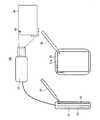
以下に図面を参照しつつ、本発明の好ましい実施の形態を示す。図1に示されるように、ヘッドマウントディスプレイ100は、ユーザーの頭部に装着されるヘッドマウントディスプレイ部50とユーザーの腰等の身体に装着される制御部30とから構成されている。ヘッドマウントディスプレイ部50は、頭部装着部51、画像生成部52とから構成されている。頭部装着部51は、図1に示される実施形態では、眼鏡のフレーム形状であるが、ヘルメット形状等であってもよく、ユーザーの頭部に装着される構造のものであれはすべて含まれる。(Overview of head mounted display)
Hereinafter, preferred embodiments of the present invention will be described with reference to the drawings. As shown in FIG. 1, the head-mounted
画像生成部52は、頭部装着部51の側前部に取り付けられている。画像生成部52は、画像を生成し、当該画像をユーザーに視認させるものである。本実施形態では、画像生成部52は、レーザ光を直接ユーザーの眼球に走査することにより、ユーザーに画像を視認させる網膜走査型ディスプレイを用いて構成される。このように、網膜走査型ディスプレイを用いて画像生成部52を構成すると、ユーザーは画像生成部52が生成する画像を視認することができると同時に、外界もまた視認することができる。なお、画像生成部52は、液晶ディスプレイ、有機EL(Organic Electroluminescence)ディスプレイなど、その他の装置を用いた構成であっても差し支えない。 The
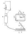
制御部30は、ユーザーの記入操作を検出する装置である。制御部30は、画像生成部52と接続している。制御部30には、ヘッドマウントディスプレイ100を操作するための操作部35が設けられている。また、図2に示されるように、制御部30には、記入操作検出部31が設けられている。記入操作検出部31は、2次元である検出領域31a上の、ユーザーの記入操作の座標を検出する装置である。本実施形態では、ユーザーが入力ペン80で検出領域31a上に記入操作を行うと、この記入操作による検出領域31a上の座標が「記入操作座標」として、記入操作検出部31で検出されるようになっている。 The
検出領域31aの絶対座標と、画像生成部52の表示領域90の絶対座標は一致している。ところが、本発明では、ユーザーが検出領域31a上で文字を記入する場合には、制御部30が記入操作検出部31で検知された開始位置座標91を、画像生成部52の表示領域90上の所望の初期位置座標99に変換する。従って、図2に示されるように、ユーザーが、検出領域31a上の任意の開始位置座標91からペン入力を始めた場合であっても、表示領域90の所望の初期位置から、ユーザーの記入による軌跡が表示される。
以下、このような機能を実現するヘッドマウントディスプレイ100について詳細に説明する。The absolute coordinates of the
Hereinafter, the head mounted
(ヘッドマウントディスプレイのブロック図)
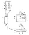
図3を用いて、ヘッドマウントディスプレイ100のブロック図を説明する。制御部30には、ヘッドマウントディスプレイ100の各種制御を行う制御基板20を有している。制御基板20は、CPU10、RAM11、ROM12、補助記憶装置13、画像生成コントローラ16、VRAM17、インターフェース19を有している。これらの構成は、相互にバス9で接続されている。画像生成コントローラ16とVRAM17も相互に接続している。(Block diagram of head-mounted display)
A block diagram of the head mounted
CPU(Central Processing Unitの略)10は、RAM(Random Access Memoryの略)11、ROM(Read Only Memoryの略)12と協動して、各種演算、処理を行うものである。 A CPU (abbreviation of central processing unit) 10 performs various calculations and processes in cooperation with a RAM (abbreviation of random access memory) 11 and a ROM (abbreviation of read only memory) 12.
RAM11は、CPU10で処理されるプログラムや、CPU10が処理するデータを、そのアドレス空間に一時的に記憶するものである。RAM11は、記入操作座標記憶領域11a、初期位置座標記憶領域11b、開始位置座標記憶領域11c、記入軌跡座標記憶領域11dを有している。
記入操作座標記憶領域11aには、バス9に入力された「記入操作座標」が記憶される。
初期位置座標記憶領域11bには、後述する初期位置座標決定プログラム12cが決定した画像生成部52の表示領域90上の「初期位置座標」が記憶される。
開始位置座標記憶領域11cには、ユーザーの入力ペン80による検出領域31aへの記入操作の開始位置の座標である「開始位置座標」が記憶される。
記入軌跡座標記憶領域11dには、座標変換プログラム12eにより生成された「記入軌跡座標」が記憶される。The RAM 11 temporarily stores programs processed by the
In the entry operation coordinate
In the initial position coordinate
The start position coordinate
In the entry locus coordinate
ROM12には、ヘッドマウントディスプレイ100を制御する各種プログラムやパラメータが記憶されている。当該各種プログラムが、CPU10で処理されることにより、各種機能を実現している。ROM12には、モード選択画面表示プログラム12a、モード選択プログラム12b、初期位置座標決定プログラム12c、開始位置座標検出プログラム12d、座標変換プログラム12e、記入軌跡画像生成プログラム12f、記入操作エラー検出プログラム12g、警告報知プログラム12hが記憶されている。なお、補助記憶装置13に、これらプログラムやデータを記憶することにしても差し支えない。 The
モード選択画面表示プログラム12aは、「文字入力モード」であるか「描画入力モード」であるかを選択させる「入力モード選択画面」(図5に示す)を、画像生成部52の表示領域90上に表示させる命令を、画像生成コントローラ16に出力する。
モード選択プログラム12bは、ユーザーの選択操作により、「文字入力モード」又は「描画入力モード」のいずれかが選択されたかを判断するプログラムである。
初期位置座標決定プログラム12cは、画像生成部52の表示領域90上の初期位置座標99(図7〜図11に示す)を決定するプログラムである。
開始位置座標検出プログラム12dは、「記入操作座標」から、ユーザーによる書き始め位置である開始位置座標91(図7〜図11に示す)を検出するプログラムである。
座標変換プログラム12eは、ユーザーによる記入操作の開始位置座標91を、画像生成部52の表示領域90上の初期位置座標99に変換し、初期位置座標99と、「記入操作座標」と開始位置座標91との位置関係を用いて、順次「記入軌跡座標」を算出するプログラムである。
記入軌跡画像生成プログラム12fは、前記算出された「記入軌跡座標」に基づいて、画像生成部52に出力する「記入軌跡画像」を生成するプログラムである。
記入操作エラー検出プログラム12gは、ユーザーの記入操作の検出領域31a外への近接又は離脱を検出するプログラムである。
警告報知プログラム12hは、ユーザーの記入操作の検出領域31a外への近接又は離脱を検出した場合に、画像生成部52に警告画像を表示させ、ユーザーに警告を報知するプログラムである。
なお、モード選択画面表示プログラム12a、モード選択プログラム12b、初期位置座標決定プログラム12c、開始位置座標検出プログラム12d、座標変換プログラム12e、記入軌跡画像生成プログラム12f、記入操作エラー検出プログラム12g、警告報知プログラム12hを、ASIC(Application Specific IntegratedCircuit)として構成することとしても差し支えない。The mode selection screen display program 12 a displays an “input mode selection screen” (shown in FIG. 5) on the
The
The initial position coordinate
The start position coordinate
The coordinate
The entry trajectory image generation program 12f is a program that generates an “entry trajectory image” to be output to the
The entry operation
The
It should be noted that the mode selection screen display program 12a, the
補助記憶装置13は、例えば、不揮発性メモリーやハードディスクである。補助記憶装置13には、記入軌跡座標保存領域13a、記入操作座標保存領域13bを有している。記入軌跡座標保存領域13aには、「文字入力モード」の場合に、ユーザーの検出領域31a上の記入操作により生成された「記入軌跡座標」が記憶される。記入操作座標保存領域13bには、「描画入力モード」の場合に、ユーザーの検出領域31a上の記入操作により生成された「記入操作座標」が記憶される。 The auxiliary storage device 13 is, for example, a nonvolatile memory or a hard disk. The auxiliary storage device 13 has an entry trajectory coordinate
画像生成コントローラ16は、GPU(Graphics Processing Unit)を有している。画像生成コントローラ16は、記入軌跡画像生成プログラム12cからの描画命令により、「記入操作軌跡画像」を生成し、VRAM17に記憶させる。VRAM17に記憶された「記入操作軌跡画像」は、「画像信号」として画像生成部52に出力される。 The
インターフェース19は、信号の物理的、論理的な形式を変換するものである。インターフェース19は、記入操作検出部31や操作部35と接続している。操作部35は、ボタンやタッチパネルで構成されている。操作部35は、ユーザーの操作により、ヘッドマウントディスプレイ100をON状態(電源が投入された状態)やOFF状態(電源が遮断された状態)にし、ヘッドマウントディスプレイ100の各種操作を行うためのものである。 The
本実施形態では、入力ペン80の先端は交番磁界を発し、記入操作検出部31には前記交番磁界を検知する検知コイルがマトリックス状に配設されている。このような構成により、記入操作検出部31で、2次元である検出領域31a上の、ユーザーの記入操作の座標である「記入操作座標」が生成される。この「記入操作座標」は、所定時間(数ミリ秒)をおいて生成される。但し、ユーザーが入力ペン80を、記入操作検出部31の検出領域31aから離した場合には、「記入操作座標」は生成されない。生成された「記入操作座標」は、インターフェース19を介して、バス9に出力される。 In the present embodiment, the tip of the
(ヘッドマウントディスプレイのフローの説明)
図4を用いて、ヘッドマウントディスプレイ100の処理フローについて説明する。ユーザーが操作部35を操作することにより、ヘッドマウントディスプレイ100に電源が投入されると、ヘッドマウントディスプレイ100の処理フローが開始し、S11の処理に進む。
S11「起動処理」において、ヘッドマウントディスプレイ100の各種プログラムが起動する。S11の処理が終了すると、S12の処理に進む。(Explanation of head-mounted display flow)
A processing flow of the head mounted
In S11 “activation process”, various programs of the head mounted
S12「入力モード選択画面を表示」の処理において、モード選択画面表示プログラム12aは、「文字入力モード」であるか「描画入力モード」であるかを選択させる「入力モード選択画面」を、画像生成部52に表示させる命令を、画像生成コントローラ16に出力する。すると、図5に示されるように、「文字入力モード」及び「描画入力モード」のボタンからなる「入力モード選択画面」が画像生成部52に表示される。更に、モード選択プログラム12bは、画像生成部52の表示領域90上に、ポインター97を表示される命令を、画像生成コントローラ16に出力する。すると、図5に示されるように、ポインター97が画像生成部52の表示領域90上に表示される。なお、ポインター97が、画像生成部52の表示領域90上に、表示されている状態で、ユーザーが入力ペン80の先端を、記入操作検出部31の検出領域31aに押し当てたまま所定の位置まで移動させる「ドラッグ操作」を行うと、ポインター97が前記「ドラッグ操作」に伴って移動する。S12の処理が終了すると、S13の判断処理に進む。 In the process of S12 “display input mode selection screen”, the mode selection screen display program 12a generates an “input mode selection screen” for selecting “character input mode” or “drawing input mode”. A command to be displayed on the
S13「文字入力モードか?」の判断処理において、モード選択プログラム12bは、ユーザーの入力ペン80の操作により、「文字入力モード」が選択されたか否かを判断する。ユーザーが、入力ペン80の操作することによりポインター97を「文字入力モード」のボタン上まで移動した後に、「選択操作」を行った場合には、モード選択プログラム12bは、「文字入力モード」が選択されたと判断し(S13の判断処理がYES)、S14の判断処理に進む。
一方で、ユーザーが、入力ペン80の操作することによりポインター97を「描画入力モード」のボタン上まで移動した後に、「選択操作」を行った場合には、モード選択プログラム12bは、「描画入力モード」が選択されたと判断し(S13の判断処理がNO)、S51の処理に進む。なお、「選択操作」としては、例えばユーザーが選択ペン80の先端を検出領域31a上で離しては着ける動作を2回繰り返すダブルクリック操作などが含まれる。In the determination process of S13 “character input mode?”, The
On the other hand, when the user performs the “selection operation” after moving the
S14「初期位置入力あり?」の判断処理において、初期位置座標決定プログラム12cは、初期位置入力があったか否かを判断する。具体的には、ユーザーが入力ペン80の先端を、記入操作検出部31の検出領域31aに接触させると、初期位置座標決定プログラム12cは、初期位置入力があったと判断し(S14の判断処理がYES)、S15の処理に進む。一方で、初期位置座標決定プログラム12cが、初期位置入力があったと判断しない場合には(S14の判断処理がNO)、S15の処理に進まない。 In the determination process of S14 “Is there an initial position input?”, The initial position coordinate
S15「絶対座標で初期位置マークを表示」の処理において、初期位置座標決定プログラム12cは、S14の処理で検出された検出領域31a上の操作ペン80先端の絶対座標に対応する、表示領域90上の位置に初期位置マーク98を表示する描画命令を、画像生成コントローラ16に出力する。すると、図6に示されるように、画像生成部52の表示領域90上に初期位置マーク98が表示される。S15の処理が終了すると、S16の処理に進む。 In the process of S15 “display initial position mark with absolute coordinates”, the initial position coordinate
S16「初期位置決定入力あり?」の判断処理において、初期位置座標決定プログラム12cは、初期位置決定入力があったか否かを判断する。具体的には、ユーザーが操作部35を操作することにより、初期位置座標決定プログラム12cが、初期位置決定入力があったと判断した場合には(S16の判断処理がYES)、初期位置座標決定プログラム12cは、画像生成部52の表示領域90の初期位置マーク98が表示されている座標を「初期位置座標」として、RAM11の初期位置座標記憶領域11bに記憶させて、S17の判断処理に進む。一方で、初期位置座標決定プログラム12cが、初期位置決定入力があったと判断しない場合には(S16の判断処理がNO)、S17の判断処理に進まない。このように、本発明では、ユーザーが「初期位置座標」として画像生成部52の表示領域90上の任意の位置を選択することができる。 In the determination process of S16 “Is there an initial position determination input?”, The initial position coordinate
S17「記入操作有り?」の判断処理において、CPU10は、ユーザーによる記入操作があったか否かを判断する。具体的には、ユーザーが入力ペン80で、記入操作検出部31の検出領域31a上に記入操作を行うことにより、「記入操作座標」がインターフェース19を介してバス9に入力されたと、CPU10が判断した場合には(S17の判断処理がYES)、S18の処理に進む。この際に、開始位置座標検出プログラム12dは、時系列的に最も古い「記入操作座標」を「開始位置座標」としてRAM11の開始位置座標記憶領域11cに記憶させる。一方で、CPU10が、「記入操作座標」がインターフェース19を介してバス9に入力されたと判断しない場合には(S17の判断処理がNO)、S18の処理に進まない。 In the determination process of S17 “Is there an entry operation?”, The
S18「記入操作座標の記憶開始」の処理において、CPU10は、バスに入力された「記入操作座標」を、RAM11の記入操作座標記憶領域11aに記憶させる処理を開始させる。S18の処理が終了すると、S19の処理に進む。 In the process of S18 “start storage of entry operation coordinates”, the
S19「記入軌跡座標算出開始」の処理において、座標変換プログラム12eは、画像生成部52の表示領域90に表示される、ユーザー記入操作の軌跡座標である「記入軌跡座標」の算出を開始させる。座標変換プログラム12eが、「記入軌跡座標」を算出する処理について次に説明する。
座標変換プログラム12eは、RAM12の初期位置座標記憶領域11bと開始位置座標記憶領域11cを参照することにより、「初期位置座標」及び「開始位置座標」を認識する。そして、図7に示されるように、座標変換プログラム12eは、ユーザーによる記入操作の開始位置座標91を、画像生成部52の表示領域90上の初期位置座標99に変換する。
次に、座標変換プログラム12eは、RAM11の記入操作座標記憶領域11aを参照することにより、「記入操作座標」を認識する。そして、座標変換プログラム12eは、初期位置座標99と、「記入操作座標」と開始位置座標91との位置関係を用いて、順次「記入軌跡座標」を算出する。本実施形態では、座標変換プログラム12eは、初期位置座標99に、「記入操作座標」と開始位置座標91との差分値(図8に示されるX’、Y’)を加算することにより、順次「記入軌跡座標」を算出する。算出された「記入軌跡座標」は、RAM11の記入軌跡座標記憶領域11dに記憶される。
S19の処理が終了すると、S20の処理に進む。In the process of S19 “start entry locus coordinate calculation”, the coordinate
The coordinate
Next, the coordinate
When the process of S19 ends, the process proceeds to S20.
S20「画像表示部への表示開始」の処理において、記入軌跡画像生成プログラム12fは、記入軌跡座標記憶領域11dに記憶されている「記入軌跡座標」に基づいて、「表示領域軌跡画像」を生成する。具体的には、記入軌跡画像生成プログラム12fは、時系列的に隣接する「記入軌跡座標」同士を結ぶ線を生成する描画命令を、画像生成コントローラ16に出力する。但し、時系列的に隣接する「記入軌跡座標」が所定距離以上離れている場合には、ユーザーが入力ペン80を、記入操作検出部31の検出領域31aから離しているので、時系列的に隣接する「記入軌跡座標」は結ばない。
時系列的に隣接する「記入軌跡座標」同士を結ぶ線を生成する描画命令が、画像生成コントローラ16に入力されると、図8に示されるように、画像生成部52の表示領域90上に文字である「表示領域軌跡画像」が表示される。S20の処理が終了すると、S21の判断処理に進む。In the process of S20 “Start display on image display unit”, the entry locus image generation program 12f generates a “display area locus image” based on the “entry locus coordinates” stored in the entry locus coordinate
When a drawing command for generating a line connecting adjacent “entry trajectory coordinates” in time series is input to the
S21「検出領域外に近接?」の判断処理において、記入操作エラー検出プログラム12gは、ユーザーの記入操作(入力ペン80の先端)の、検出領域31a外へ近接又は離脱を検出したか否かを判断する。なお、図9に示されるように、記入操作検出部31は、検出領域31aの外縁から当該外縁からやや内側位置まで近接警告領域31bを有している。そして、ユーザーの記入操作が、近接警告領域31bに侵入した場合には、記入操作エラー検出プログラム12gは、ユーザーの記入操作が検出領域31a外へ近接したと判断する。また、ユーザーの記入操作が、近接警告領域31bに侵入した後に、検出領域31aからユーザーの記入操作が検出されなくなった場合には、記入操作エラー検出プログラム12gは、ユーザーの記入操作が検出領域31a外へ離脱したと判断する。
記入操作エラー検出プログラム12gが、ユーザーの記入操作の検出領域31a外へ近接又は離脱を検出した場合には(S21の判断処理YES)、S31の処理に進む。
一方で、記入操作エラー検出プログラム12gが、ユーザーの記入操作の検出領域31a外へ近接又は離脱を検出しない場合には(S21の判断処理NO)、S41の処理に進むIn the determination processing of S21 “proximity outside detection area?”, The entry operation
If the entry operation
On the other hand, when the entry operation
S31「警告を報知」の処理において、警告報知プログラム12hは、画像生成部52で警告を表示する描画命令を画像生成コントローラ16に出力する。すると、図10に示されるように、画像生成部52に警告が表示される。
或いは、ヘッドマウントディスプレイ100にスピーカを設け、当該スピーカで警告音を再生して、ユーザーに警告を報知する実施形態であっても差し支えない。
S31の処理が終了すると、S32の判断処理に進む。In the processing of S31 “notify warning”, the
Alternatively, an embodiment in which a speaker is provided in the head mounted
When the process of S31 ends, the process proceeds to the determination process of S32.
S32「記入操作座標が所定以上変化?」の判断処理において、記入操作エラー検出プログラム12gは、RAM11の記入操作座標記憶領域11aを参照することにより、「記入操作座標」が所定以上変化したか否かを判断する。つまり、ユーザーがS31の処理で報知される警告を知覚することにより、入力ペン80を検出領域31aの内側に移動させた場合には、「記入操作座標」が所定以上変化する。記入操作エラー検出プログラム12gが、「記入操作座標」が所定以上変化したと判断した場合には(S32の判断処理がYES)、S33の処理に進む。一方で、記入操作エラー検出プログラム12gが、「記入操作座標」が所定以上変化したと判断しない場合には(S32の判断処理がNO)、S33の処理に進まない。 In the determination process of S32 “change in input operation coordinates by more than a predetermined value?”, The input operation
S33「記入軌跡座標再算出」の処理において、座標変換プログラム12eは、S21の判断処理において記入操作エラー検出プログラム12gがユーザーの記入操作の検出領域外への近接又は離脱を検出した時点の記入軌跡座標92(図10や図11に示す)と、記入操作検出部31が再び検出した後の、開始位置座標93と記入操作座標94(図11に示す)との位置関係を用いて記入軌跡座標95(図11に示す)を算出する。本実施形態では、座標変換プログラム12eは、前記記入軌跡座標92に、前記記入操作座標94と開始位置座標93との差分値(図11に示されるX’’、Y’’)を加算して、記入軌跡座標95を算出している。算出された「記入軌跡座標」は、RAM11の記入軌跡座標記憶領域11dに記憶される。更に、図11に示されるように、再算出された「記入軌跡座標」に基づいて、画像生成部52の表示領域90に「表示領域軌跡画像」が表示される。
このように、ユーザーが検出領域31aの外側に離脱しそうになった入力ペン80を、検出領域31aの内側に移動させた場合には、S33の処理において、「記入軌跡座標」が再算出されるので、途切れなく「記入軌跡座標」が算出され、画像生成部52の表示領域90に「表示領域軌跡画像」が表示される。S33の処理が終了すると、S41の判断処理に進む。In the process of S33 "Recalculation of entry locus coordinates", the coordinate
In this way, when the
S41「文字入力モード解除?」の判断処理において、CPU10は、ユーザーが操作部35を操作することにより、「文字入力モード」を解除する信号がバス9に入力されたか否かを判断する。CPU10が、「文字入力モード」を解除する信号がバス9に入力されたと判断した場合には(S41の判断処理がYES)、S44の処理に進む。一方で、CPU10が、「文字入力モード」を解除する信号がバス9に入力されていないと判断した場合には(S41の判断処理がNO)、S42の判断処理に進む。 In the determination process of S41 “character input mode cancel?”, The
S42「所定時間記入操作無し?」の判断処理において、CPU10は、所定時間(例えば数分)以上、ユーザーによる記入操作検出部31の検出領域31aへの記入操作が無かったか否かを判断する。具体的には、CPU10が、所定時間以上、バス9に「記入操作座標」が入力されなかったと判断した場合には(S42の判断処理がYES)、S44の処理に進む。一方で、CPU10が、所定時間内に、バス9に「記入操作座標」が入力された判断した場合には(S42の判断処理がNO)、S46の処理に進む。 In the determination process of S42 “no entry operation for a predetermined time?”, The
S44「記入軌跡座標を保存」の処理において、CPU10は、RAM11の記入軌跡座標記憶領域11dに記憶されている「記入軌跡座標」を、補助記憶装置13の記入軌跡座標保存領域13aに保存させる。このように、記入軌跡座標保存領域13aに「記入軌跡座標」を保存させることにより、事後的に、ユーザーの記入内容を利用することができる。S44の処理が終了すると、S12の処理に戻る。 In the process of S44 “Save entry locus coordinates”, the
S46「終了?」の判断処理において、CPU10は、ユーザーが操作部35を操作することにより、「終了信号」がバス9に入力されたか否かを判断する。CPU10が、「終了信号」がバス9に入力されたと判断した場合には(S46の判断処理がYES)、S47の処理に進む。CPU10が、「終了信号」がバス9に入力されていないと判断した場合には(S46の判断処理がNO)、S21の判断処理に戻る。 In the determination process of S46 “End?”, The
S47「記入軌跡座標を保存」の処理において、CPU10は、RAM11の記入軌跡座標記憶領域11dに記憶されている「記入軌跡座標」を、補助記憶装置13の記入軌跡座標保存領域13aに保存させる。S47の処理が終了すると、ヘッドマウントディスプレイ100がOFF状態となり、一連のフローが終了する。 In the process of S47 “Save entry locus coordinates”, the
S51「記入操作座標の記憶開始」の処理において、CPU10は、バスに入力された「記入操作座標」を、RAM11の記入操作座標記憶領域11aに記憶させる処理を開始させる。S51の処理が終了すると、S52の処理に進む。 In the process of S51 “start of entry operation coordinates”, the
S52「記入操作軌跡の表示開始」の処理において、記入軌跡画像生成プログラム12fは、RAM11の記入操作座標記憶領域11aに記憶されている「記入操作座標」に基づいて、「表示領域軌跡画像」を生成する。具体的には、記入軌跡画像生成プログラム12fは、時系列的に隣接する「記入操作座標」同士を結ぶ線を生成する描画命令を、画像生成コントローラ16に出力する。但し、時系列的に隣接する「記入操作座標」が所定距離以上離れている場合には、ユーザーが入力ペン80を、記入操作検出部31の検出領域31aから離していると考えられるので、時系列的に隣接する「記入操作座標」は結ばない。時系列的に隣接する「記入操作座標」同士を結ぶ線を生成する描画命令が、画像生成コントローラ16に入力されると、画像生成部52の表示領域90上に「表示領域軌跡画像」が表示される。つまり、入力モードが「描画入力モード」である場合には、ユーザーが入力ペン80で検出領域31aに記入した内容がそのまま画像生成部52の表示領域90に表示される。S52の処理が終了すると、S53の判断処理に進む。 In the processing of S52 “start display of entry operation locus”, the entry locus image generation program 12f creates a “display area locus image” based on the “entry operation coordinates” stored in the entry operation coordinate
S53「描画入力モード解除?」の判断処理において、CPU10は、ユーザーが操作部35を操作することにより、「描画入力モード」を解除する信号がバス9に入力されたか否かを判断する。CPU10が、「描画入力モード」を解除する信号がバス9に入力されたと判断した場合には(S53の判断処理がYES)、S55の処理に進む。一方で、CPU10が、「描画入力モード」を解除する信号がバス9に入力されていないと判断した場合には(S53の判断処理がNO)、S54の判断処理に進む。 In the determination process of S53 “drawing input mode?”, The
S54「所定時間記入操作無し?」の判断処理において、CPU10は、所定時間(例えば数分)以上、ユーザーによる記入操作検出部31の検出領域31aへの記入操作が無かったか否かを判断する。具体的には、CPU10が、所定時間以上、バス9に「記入操作座標」が入力されなかったと判断した場合には(S54の判断処理がYES)、S55の処理に進む。一方で、CPU10が、所定時間内に、バス9に「記入操作座標」が入力された判断した場合には(S54の判断処理がNO)、S56の判断処理に進む。 In the determination process of S54 “no entry operation for a predetermined time?”, The
S55「記入操作座標を保存」の処理において、CPU10は、RAM11の記入操作座標記憶領域11aに記憶されている「記入操作座標」を、補助記憶装置13の記入操作座標保存領域13bに記憶させる。S55の処理が終了すると、S12の処理に戻る。 In the process of S55 “Save entry operation coordinates”, the
S56「終了?」の判断処理において、CPU10は、ユーザーが操作部35を操作することにより、「終了信号」がバス9に入力されたか否かを判断する。CPU10が、「終了信号」がバス9に入力されたと判断した場合には(S56の判断処理がYES)、S47の処理に進む。CPU10が、「終了信号」がバス9に入力されていないと判断した場合には(S56の判断処理がNO)、S53の判断処理に戻る。 In the determination process of S <b> 56 “end?”, The
S57「記入操作座標を保存」の処理において、CPU10は、RAM11の記入操作座標記憶領域11aに記憶されている「記入操作座標」を、補助記憶装置13の記入操作座標保存領域13bに記憶させる。S57の処理が終了すると、ヘッドマウントディスプレイ100がOFF状態となり、一連のフローが終了する。 In the process of S57 “Save entry operation coordinates”, the
入力ペン80を、赤外線や超音波を発生する構成とし、入力検出部31は前記赤外線や超音波を受信する構成とし、入力検出部31でユーザーの記入操作を検出することにしても差し支えない。
或いは、検出領域31aを撮像して、ユーザーの記入操作を検出する構成にしても差し支えない。
また、入力検出部31を感圧式や静電容量式のタッチパネルで構成しても差し支えない。
以上説明した実施形態では、ユーザーが入力ペン80を用いて、入力検出部31の検出領域31aに記入操作を行っているが、入力検出部31をタッチパネルで構成するか、もしくは、入力検出部31を撮像する構成とすることにより、ユーザーが指で検出領域31aに記入操作を行い、入力検出部31が前記記入操作を検出する実施形態であっても差し支えない。The
Alternatively, the
Further, the
In the embodiment described above, the user performs an entry operation in the
以上、現時点において、もっとも、実践的であり、かつ好ましいと思われる実施形態に関連して本発明を説明したが、本発明は、本願明細書中に開示された実施形態に限定されるものではなく、請求の範囲および明細書全体から読み取れる発明の要旨あるいは思想に反しない範囲で適宜変更可能であり、そのような変更を伴うヘッドマウントディスプレイもまた技術的範囲に包含されるものとして理解されなければならない。 Although the present invention has been described above in connection with the most practical and preferred embodiments at the present time, the present invention is not limited to the embodiments disclosed herein. However, the present invention can be appropriately changed without departing from the gist or concept of the invention that can be read from the claims and the entire specification, and a head-mounted display accompanying such a change should also be understood as being included in the technical scope. I must.
9 バス
10 CPU
11 RAM
11a 記入操作座標記憶領域
11b 初期位置座標記憶領域
11c 開始位置座標記憶領域
11d 記入軌跡座標記憶領域
12 ROM
12a モード選択画面表示プログラム
12b モード選択プログラム
12c 初期位置座標決定プログラム
12d 開始位置座標検出プログラム
12e 座標変換プログラム
12f 記入軌跡画像生成プログラム
12g 記入操作エラー検出プログラム
12h 警告報知プログラム
13 補助記憶装置
13a 記入軌跡座標保存領域
13b 記入操作座標保存領域
16 画像生成コントローラ
17 VRAM
19 インターフェース
30 制御部
31 記入操作検出部
31a 検出領域
31b 近接警告領域
35 操作部
50 ヘッドマウントディスプレイ部
51 頭部装着部
52 画像生成部
80 入力ペン
90 表示領域
91 開始位置座標
92 記入軌跡座標
93 開始位置座標
94 記入操作座標
95 記入軌跡座標
96 警告
97 ポインター
98 初期位置マーク
99 初期位置座標
100 ヘッドマウントディスプレイ9
11 RAM
11a Entry operation coordinate
12a mode selection
DESCRIPTION OF
Claims (5)
Translated fromJapaneseユーザーの身体に装着され、2次元である検出領域上のユーザーの記入操作の座標である記入操作座標を検出する記入操作検出手段と、
前記記入操作座標に基づいて、記入操作の軌跡画像を生成し、前記画像生成部に出力する記入軌跡画像生成手段と、
前記記入操作座標に基づき、ユーザーによる記入操作の前記検出領域上の開始位置座標を検出するとともに、当該開始位置座標を前記画像生成部の表示領域上の初期位置座標に変換し、更に、前記初期位置座標と、前記記入操作座標と前記開始位置座標との位置関係を用いて、前記表示領域上の記入軌跡座標を決定する座標変換手段とを有し、
前記記入軌跡画像生成手段は、前記記入軌跡座標に基づいて記入操作の軌跡画像を生成することを特徴とするヘッドマウントディスプレイ。An image generator mounted on the user's head and allowing the user to visually recognize the image;
An entry operation detection means for detecting entry operation coordinates, which is a coordinate of the entry operation of the user on a detection area which is two-dimensionally attached to the user's body;
Based on the entry operation coordinates, an entry locus image generation means for generating a locus image of the entry operation and outputting it to the image generation unit;
Based on the entry operation coordinates, the start position coordinates on the detection area of the entry operation by the user are detected, the start position coordinates are converted into initial position coordinates on the display area of the image generation unit, and the initial position coordinates are further converted. Coordinate conversion means for determining the entry locus coordinates on the display area using the position coordinates and the positional relationship between the entry operation coordinates and the start position coordinates,
The entry locus image generation means generates an entry locus image based on the entry locus coordinates.
前記記入操作エラー検出手段が、ユーザーの記入操作の検出領域外への近接又は離脱を検出した場合において、記入操作検出手段がユーザーの記入操作を再び検出した場合に、
座標変換手段は、前記記入操作エラー検出手段がユーザーの記入操作の検出領域外への近接又は離脱を検出した時点の記入軌跡座標に、記入操作検出手段が再び検出した記入操作座標と開始位置座標との位置関係を用いて記入軌跡座標を決定することを特徴とする請求項1に記載のヘッドマウントディスプレイ。It further has an entry operation error detection means for detecting approaching or leaving the detection area of the entry operation of the user, and
In the case where the entry operation error detection means detects the proximity or separation of the user entry operation outside the detection area, and the entry operation detection means detects the user entry operation again,
The coordinate conversion means includes the entry operation coordinates and the start position coordinates detected again by the entry operation detection means in the entry trajectory coordinates when the entry operation error detection means detects approaching or leaving the detection area of the entry operation of the user. The head-mounted display according to claim 1, wherein the entry locus coordinates are determined using a positional relationship between the head-mounted display and the head-mounted display.
前記検出領域外近接検出手段が、ユーザーの記入操作の検出領域外への近接を検出した場合に、ユーザーに警告を報知する警告報知手段を更に有することを特徴とする請求項1又は請求項2に記載のヘッドマウントディスプレイ。In addition to having a detection area proximity detection means for detecting the proximity of the user's entry operation outside the detection area,
The warning detection means for notifying the user of a warning when the proximity detection means outside the detection area detects the proximity of the user's entry operation outside the detection area. The head mounted display as described in.
モード選択手段は、ユーザーの記入操作が文字入力であると判断した場合には、座標変換手段を起動させ、前記モード選択手段がユーザーの記入操作が文字入力でないと判断した場合には、座標変換手段を起動させない制御を行い、
記入軌跡画像生成手段は、前記モード選択手段がユーザーの記入操作が文字入力でないと判断した場合には、記入操作検出手段が検出した記入操作座標に基づいて、記入操作の軌跡画像を生成することを特徴とする請求項1〜請求項3のいずれかに記載のヘッドマウントディスプレイ。Mode selection means for determining whether or not the user's entry operation is a character input;
The mode selection means activates the coordinate conversion means when it is determined that the user's entry operation is a character input, and the coordinate selection means when the mode selection means determines that the user's entry operation is not a character input. Control that does not start the means,
The entry trajectory image generating means generates a trajectory image of the entry operation based on the entry operation coordinates detected by the entry operation detecting means when the mode selecting means determines that the user's entry operation is not a character input. The head mounted display in any one of Claims 1-3 characterized by these.
Priority Applications (2)
| Application Number | Priority Date | Filing Date | Title |
|---|---|---|---|
| JP2009292164AJP5207145B2 (en) | 2009-12-24 | 2009-12-24 | Head mounted display |
| US12/967,518US20110157005A1 (en) | 2009-12-24 | 2010-12-14 | Head-mounted display |
Applications Claiming Priority (1)
| Application Number | Priority Date | Filing Date | Title |
|---|---|---|---|
| JP2009292164AJP5207145B2 (en) | 2009-12-24 | 2009-12-24 | Head mounted display |
Publications (2)
| Publication Number | Publication Date |
|---|---|
| JP2011134054A JP2011134054A (en) | 2011-07-07 |
| JP5207145B2true JP5207145B2 (en) | 2013-06-12 |
Family
ID=44186863
Family Applications (1)
| Application Number | Title | Priority Date | Filing Date |
|---|---|---|---|
| JP2009292164AExpired - Fee RelatedJP5207145B2 (en) | 2009-12-24 | 2009-12-24 | Head mounted display |
Country Status (2)
| Country | Link |
|---|---|
| US (1) | US20110157005A1 (en) |
| JP (1) | JP5207145B2 (en) |
Families Citing this family (14)
| Publication number | Priority date | Publication date | Assignee | Title |
|---|---|---|---|---|
| US8194036B1 (en)* | 2011-06-29 | 2012-06-05 | Google Inc. | Systems and methods for controlling a cursor on a display using a trackpad input device |
| US20130021269A1 (en)* | 2011-07-20 | 2013-01-24 | Google Inc. | Dynamic Control of an Active Input Region of a User Interface |
| US9483086B2 (en) | 2012-07-30 | 2016-11-01 | Sap Se | Business object detail display |
| US9123030B2 (en) | 2012-07-30 | 2015-09-01 | Sap Se | Indication of off-screen calendar objects |
| US9658672B2 (en) | 2012-07-30 | 2017-05-23 | Sap Se | Business object representations and detail boxes display |
| US20140059455A1 (en)* | 2012-08-22 | 2014-02-27 | Sap Ag | System and method for efficiently selecting data entities represented in a graphical user interface |
| US8832583B2 (en) | 2012-08-31 | 2014-09-09 | Sap Se | Visualizing entries in a calendar using the third dimension |
| US9081466B2 (en) | 2012-09-10 | 2015-07-14 | Sap Se | Dynamic chart control that triggers dynamic contextual actions |
| US9250781B2 (en) | 2012-10-17 | 2016-02-02 | Sap Se | Method and device for navigating time and timescale using movements |
| US8972883B2 (en) | 2012-10-19 | 2015-03-03 | Sap Se | Method and device for display time and timescale reset |
| JP6160154B2 (en) | 2013-03-22 | 2017-07-12 | セイコーエプソン株式会社 | Information display system using head-mounted display device, information display method using head-mounted display device, and head-mounted display device |
| JP6237000B2 (en)* | 2013-08-29 | 2017-11-29 | セイコーエプソン株式会社 | Head-mounted display device |
| CA3027407A1 (en)* | 2014-02-18 | 2015-08-27 | Merge Labs, Inc. | Head mounted display goggles for use with mobile computing devices |
| CN104063092B (en)* | 2014-06-16 | 2016-12-07 | 青岛歌尔声学科技有限公司 | A kind of touch screen control method and device |
Family Cites Families (10)
| Publication number | Priority date | Publication date | Assignee | Title |
|---|---|---|---|---|
| JPH07306747A (en)* | 1994-05-12 | 1995-11-21 | Canon Inc | Input coordinate conversion method and apparatus |
| US5757368A (en)* | 1995-03-27 | 1998-05-26 | Cirque Corporation | System and method for extending the drag function of a computer pointing device |
| US6552719B2 (en)* | 1999-01-07 | 2003-04-22 | Microsoft Corporation | System and method for automatically switching between writing and text input modes |
| JP2001273087A (en)* | 2000-03-23 | 2001-10-05 | Olympus Optical Co Ltd | Video display unit |
| US7688306B2 (en)* | 2000-10-02 | 2010-03-30 | Apple Inc. | Methods and apparatuses for operating a portable device based on an accelerometer |
| JP2004094653A (en)* | 2002-08-30 | 2004-03-25 | Nara Institute Of Science & Technology | Information input system |
| WO2005116939A1 (en)* | 2004-05-27 | 2005-12-08 | Canon Kabushiki Kaisha | Information processing method, information processing apparatus, and image sensing apparatus |
| US20070220108A1 (en)* | 2006-03-15 | 2007-09-20 | Whitaker Jerry M | Mobile global virtual browser with heads-up display for browsing and interacting with the World Wide Web |
| JP2008009490A (en)* | 2006-06-27 | 2008-01-17 | Konica Minolta Holdings Inc | Information input device |
| US8341556B2 (en)* | 2007-04-30 | 2012-12-25 | Hewlett-Packard Development Company, L.P. | Method and system for attention-free user input on a computing device |
- 2009
- 2009-12-24JPJP2009292164Apatent/JP5207145B2/ennot_activeExpired - Fee Related
- 2010
- 2010-12-14USUS12/967,518patent/US20110157005A1/ennot_activeAbandoned
Also Published As
| Publication number | Publication date |
|---|---|
| JP2011134054A (en) | 2011-07-07 |
| US20110157005A1 (en) | 2011-06-30 |
Similar Documents
| Publication | Publication Date | Title |
|---|---|---|
| JP5207145B2 (en) | Head mounted display | |
| JP5146845B2 (en) | Head mounted display | |
| KR102362741B1 (en) | Flexible display device and displaying method thereof | |
| JP4351599B2 (en) | Input device | |
| JP5362092B1 (en) | Electronic apparatus and drawing method | |
| JP5857255B2 (en) | Information processing apparatus, processing control method, program, and recording medium | |
| US10642381B2 (en) | Vehicular control unit and control method thereof | |
| JP2009193423A5 (en) | ||
| JP2012064075A (en) | Character input device | |
| JP2010231609A (en) | Tactile sensation presentation apparatus and method | |
| US20110254784A1 (en) | Controlling method and information processing apparatus | |
| JP5733634B2 (en) | Power management apparatus, power management method, and power management program | |
| JP2016218774A (en) | program | |
| JP2010067139A5 (en) | INFORMATION PROCESSING APPARATUS AND INFORMATION PROCESSING METHOD | |
| KR102094886B1 (en) | Display device and controlling method thereof for outputing tactile and visual feedback selectively | |
| JP5718402B2 (en) | Input device | |
| JP2016126363A (en) | Touch screen input method, mobile electronic device, and computer program | |
| JP5852514B2 (en) | Touch sensor | |
| JP2009237746A (en) | Operation device for vehicle | |
| JP2012108647A (en) | Touch panel system | |
| JP4786292B2 (en) | Information processing apparatus, hierarchical information output method, and program | |
| JP6074403B2 (en) | System, program, and method capable of pointer operation on head mounted display by touch panel type device | |
| JP2010049318A (en) | Movement control program | |
| JP2009157448A (en) | Handwritten information input display system | |
| JP4757132B2 (en) | Data input device |
Legal Events
| Date | Code | Title | Description |
|---|---|---|---|
| A621 | Written request for application examination | Free format text:JAPANESE INTERMEDIATE CODE: A621 Effective date:20120306 | |
| A977 | Report on retrieval | Free format text:JAPANESE INTERMEDIATE CODE: A971007 Effective date:20121219 | |
| TRDD | Decision of grant or rejection written | ||
| A01 | Written decision to grant a patent or to grant a registration (utility model) | Free format text:JAPANESE INTERMEDIATE CODE: A01 Effective date:20130125 | |
| A61 | First payment of annual fees (during grant procedure) | Free format text:JAPANESE INTERMEDIATE CODE: A61 Effective date:20130207 | |
| FPAY | Renewal fee payment (event date is renewal date of database) | Free format text:PAYMENT UNTIL: 20160301 Year of fee payment:3 | |
| R150 | Certificate of patent or registration of utility model | Free format text:JAPANESE INTERMEDIATE CODE: R150 Ref document number:5207145 Country of ref document:JP Free format text:JAPANESE INTERMEDIATE CODE: R150 | |
| LAPS | Cancellation because of no payment of annual fees |