JP5206957B2 - Vehicle intake structure - Google Patents
Vehicle intake structureDownload PDFInfo
- Publication number
- JP5206957B2 JP5206957B2JP2008253174AJP2008253174AJP5206957B2JP 5206957 B2JP5206957 B2JP 5206957B2JP 2008253174 AJP2008253174 AJP 2008253174AJP 2008253174 AJP2008253174 AJP 2008253174AJP 5206957 B2JP5206957 B2JP 5206957B2
- Authority
- JP
- Japan
- Prior art keywords
- air cleaner
- frame
- vehicle
- width direction
- cleaner chamber
- Prior art date
- Legal status (The legal status is an assumption and is not a legal conclusion. Google has not performed a legal analysis and makes no representation as to the accuracy of the status listed.)
- Expired - Fee Related
Links
Images


Classifications
- B—PERFORMING OPERATIONS; TRANSPORTING
- B60—VEHICLES IN GENERAL
- B60K—ARRANGEMENT OR MOUNTING OF PROPULSION UNITS OR OF TRANSMISSIONS IN VEHICLES; ARRANGEMENT OR MOUNTING OF PLURAL DIVERSE PRIME-MOVERS IN VEHICLES; AUXILIARY DRIVES FOR VEHICLES; INSTRUMENTATION OR DASHBOARDS FOR VEHICLES; ARRANGEMENTS IN CONNECTION WITH COOLING, AIR INTAKE, GAS EXHAUST OR FUEL SUPPLY OF PROPULSION UNITS IN VEHICLES
- B60K13/00—Arrangement in connection with combustion air intake or gas exhaust of propulsion units
- B60K13/02—Arrangement in connection with combustion air intake or gas exhaust of propulsion units concerning intake
- B—PERFORMING OPERATIONS; TRANSPORTING
- B60—VEHICLES IN GENERAL
- B60Y—INDEXING SCHEME RELATING TO ASPECTS CROSS-CUTTING VEHICLE TECHNOLOGY
- B60Y2200/00—Type of vehicle
- B60Y2200/10—Road Vehicles
- B60Y2200/11—Passenger cars; Automobiles
- B60Y2200/114—Racing vehicles, e.g. Formula one, Karts
Landscapes
- Engineering & Computer Science (AREA)
- Chemical & Material Sciences (AREA)
- Combustion & Propulsion (AREA)
- Transportation (AREA)
- Mechanical Engineering (AREA)
- Body Structure For Vehicles (AREA)
- Cooling, Air Intake And Gas Exhaust, And Fuel Tank Arrangements In Propulsion Units (AREA)
Description
Translated fromJapanese本発明は、改良された車両の吸気構造に関する。 The present invention relates to an improved vehicle intake structure.
従来、エアクリーナがリヤフレーム部に配置された構造を有する車両構造が知られている(例えば、特許文献1参照。)。特許文献1に記載の車両の車体フレーム構造は、フロントフレーム部と、センタフレーム部と、リヤフレーム部とを備え、リヤフレーム部のリヤロアフレームとサイドフレームとで囲まれた空間内にエアクリーナが配置されている。
ところで、エアクリーナ容量は、エンジン性能を良好に維持するため、一定量以上の容量が確保される必要がある。しかしながら、車体を小型化するとエアクリーナの配置位置が制約されて、必要容量が確保されたエアクリーナを配置することが困難となる問題があった。 By the way, the air cleaner capacity needs to be secured to a certain amount or more in order to maintain the engine performance satisfactorily. However, when the vehicle body is downsized, the arrangement position of the air cleaner is restricted, and there is a problem that it is difficult to arrange the air cleaner having a required capacity.
本発明は、前述した課題に鑑みてなされたものであり、その目的は、車両が小型化されてスペースが制約されたリヤフレーム部に、一定量以上の容量が確保されたエアクリーナを配設することができる車両の吸気構造を提供することにある。 The present invention has been made in view of the above-described problems, and an object of the present invention is to arrange an air cleaner in which a capacity of a certain amount or more is secured in a rear frame portion in which a vehicle is downsized and space is restricted. An object of the present invention is to provide an intake structure for a vehicle.
上記目的を達成するために、請求項1に係る発明は、車体フレームと、車体フレームに車幅方向に並んで配置されて運転席および助手席を構成する一対の乗員用シートと、動力を発生する内燃機関と、空気を浄化して内燃機関に供給するエアクリーナと、を備える車両の吸気構造であって、車体フレームは、車体の左右下部に配置されて前後方向に延びる一対のロアフレームと、ロアフレームの後端から上方に延びた後、内燃機関を覆うように屈曲して前方に延設される左右一対のリヤアッパフレームと、各リヤアッパフレームと各ロアフレームとをそれぞれ連結する一対のリヤ起立フレームと、を備え、内燃機関は、乗員用シート後方の略車体中心線上に配置され、エアクリーナは、空気中の塵埃を除去するエアクリーナエレメントを内蔵する第1エアクリーナ室と、内燃機関へ浄化された空気を供給する第2エアクリーナ室と、第1エアクリーナ室と第2エアクリーナ室とを連通させる接続チューブと、を備え、第1エアクリーナ室がロアフレーム、またはリヤアッパフレーム、またはリヤ起立フレームの車幅方向外側に位置すると共に、第2エアクリーナ室がロアフレーム、またはリヤアッパフレーム、またはリヤ起立フレームの車幅方向内側に位置するように、第1エアクリーナ室および第2エアクリーナ室が、ロアフレーム、またはリヤアッパフレーム、またはリヤ起立フレームの一部を車幅方向に跨いで配置されることを特徴とする。In order to achieve the above object, an invention according to
請求項1の発明によれば、エアクリーナは、第1エアクリーナ室と第2エアクリーナ室とから構成され、第1エアクリーナ室および第2エアクリーナ室が、車体フレームの一部を跨ぐように配置されているので、車体フレームで囲まれた空間が狭い場合でも、必要とされる所定容量が確保されたエアクリーナをコンパクトに配置することができる。 According to the first aspect of the present invention, the air cleaner is composed of a first air cleaner chamber and a second air cleaner chamber, and the first air cleaner chamber and the second air cleaner chamber are disposed so as to straddle a part of the vehicle body frame. Therefore, even when the space surrounded by the vehicle body frame is narrow, the air cleaner having a required predetermined capacity can be arranged in a compact manner.
また、エアクリーナは、運転席または助手席の後方、且つリヤフレーム部の略車体中心線上に位置する内燃機関の側方に配置されており、第1エアクリーナ室および第2エアクリーナ室が、ロアフレーム、またはリヤアッパフレーム、またはリヤ起立フレームの一部を車幅方向に跨いで配置されているので、低床化、コンパクト化されてスペースが制限されたリヤフレーム部に、エアクリーナをコンパクトに配置して、必要とされる所定容量を確保することができる。The air cleaner is disposed behind the driver seat or the passenger seat and on the side of the internal combustion engine located substantially on the vehicle body center line of the rear frame, and the first air cleaner chamber and the second air cleaner chamber are arranged on the lower frame,Or, because the rear upper frame or part of the rear standing frame is placed across the vehicle width direction, the air cleaner is placed compactly in the rear frame part where space is limited due to low flooring and compactness. The required predetermined capacity can be ensured.
また、ロアフレーム、またはリヤアッパフレーム、またはリヤ起立フレームの車幅方向外側に配置された第1エアクリーナ室にエアクリーナエレメントが配置されているので、エアクリーナのメンテナンススペースを広くとることができ、良好な整備性が確保される。また、第2エアクリーナ室がロアフレーム、またはリヤアッパフレーム、またはリヤ起立フレームの車幅方向内側に配置されているので、第1エアクリーナ室とともに必要とされる所定容量を確保することができる。Further, since the lower frameor the rear upper frame or the air cleaner element in the first air cleaner chamber which is disposed in the vehicle width direction outer side of the rear upright frame, are arranged, it is possible to widen the maintenance space of the air cleaner, better Serviceability is ensured. Further, since the second air cleaner chamber is arranged lower framesor the rear upper frame or in the vehicle width direction inner side of the rear upright frame, it is possible to ensure a predetermined capacity required together with the first air cleaner chamber.
以下、本発明の車両のフレーム構造に係る一実施形態について、MUV(マルチ・ユーティリティ・ビークル)を例にとって説明する。なお、図面は符号の向きに見るものとする。 Hereinafter, an embodiment of the frame structure of a vehicle according to the present invention will be described by taking MUV (multi-utility vehicle) as an example. The drawings are viewed in the direction of the reference numerals.
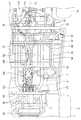
図1〜図3に示すように、本実施形態に係る車両1は、フロントフレーム部2と、センタフレーム部3と、リヤフレーム部4とを有して車体Bを構成する車体フレーム30を備える。フロントフレーム部2には、左右の前輪5を懸架する前輪用懸架装置(図示せず)が取り付けられ、フロントディファレンシャルギヤユニット81、フロントドライブシャフト82等の前輪駆動系や、前輪5を操舵する操舵部材(ステアリングシャフト6、このステアリングシャフト6の上端に取り付けたハンドル7を含む)等が支持されている。 As shown in FIGS. 1 to 3, the
センタフレーム部3には、車幅方向に並んで配置された運転席9および助手席10を構成する一対の乗員用シート11が取り付けられており、乗員の居住空間を構成する。助手席10の下部空間には、燃料タンク12が配設されると共に、運転席9と助手席10との間には、パワーユニットPとフロントディファレンシャルギヤユニット81とを連結するフロントプロペラシャフト83が配置されている。 A pair of
リヤフレーム部4には、左右の後輪15を懸架する後輪用懸架装置(図示せず)が取り付けられ、内燃機関13および変速機14を含むパワーユニットPに加え、リヤプロペラシャフト86、リヤディファレンシャルギヤユニット、リヤドライブシャフト85等の後輪駆動系等が支持されている。 A rear wheel suspension device (not shown) for suspending the left and right
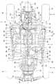
図3に示すように、リヤフレーム部4に支持されたパワーユニットPは、内燃機関13のクランクシャフト16が車体前後方向に向けて配置された縦置きレイアウトとされている。クランクシャフト16から動力が伝達される出力軸80は、略車体中心線CL上に配置され、その前端は、フロントプロペラシャフト83に連結され、後端はリヤプロペラシャフト86に連結されている。 As shown in FIG. 3, the power unit P supported by the rear frame portion 4 has a vertical layout in which the
リヤプロペラシャフト86は、略車体中心線CL上に配置されたリヤディファレンシャルギヤユニット84に接続されており、内燃機関13の駆動力は、リヤプロペラシャフト86、リヤディファレンシャルギヤユニット84、及び、リヤディファレンシャルギヤユニット84に接続されたリヤドライブシャフト85を介して左右の後輪15に伝達される。 The
フロントプロペラシャフト83には、その中間部にリダクションギヤ90が設けられており、フロントプロペラシャフト83は、リダクションギヤ90より後方に配置された第1プロペラシャフト87と、リダクションギヤ90より前方に配置された第2プロペラシャフト88とで構成される。リダクションギヤ90は、前輪5と後輪15を同一方向に回転させるため、第1プロペラシャフト87の回転方向を逆方向に変換して第2プロペラシャフト88に伝達する。これにより、内燃機関13の駆動力は、第1プロペラシャフト87、リダクションギヤ90、第2プロペラシャフト88、フロントディファレンシャルギヤユニット81、及び、フロントディファレンシャルギヤユニット81に接続されたフロントドライブシャフト82を介して左右の前輪5に伝達される。The
図8に拡大して示すように、内燃機関13のシリンダヘッド18の後部には、スロットルバルブユニット19がインテークマニホールド20を通じて接続されており、シリンダヘッド18の前部には、後述する排気管120が接続されている。スロットルバルブユニット19の後部には、後述する第1及び第2エアクリーナ室111、112を備えたエアクリーナ110がコネクティングチューブ117を介して接続される。また、スロットルバルブユニット19には、燃料タンク12から延びる燃料配管21と、バッテリケース22やECU26等を備えたバッテリケース22から配索されたワイヤハーネス23が接続されている。 As shown in an enlarged view in FIG. 8, a
さらに、図2及び図4に示すように、内燃機関13には、フロントフレーム部2に配置されたラジエータ24が2本の水配管25によって接続されており、内燃機関13を冷却する冷却水は、水配管25を介してラジエータ24との間を循環する。 Further, as shown in FIGS. 2 and 4, the
なお、図1中、26はフロントカバー、27はインストルメントパネル、28は、中央のカバー部材28aと左右一対のカバー部材28bとからなるセンターコンソールカバーである。 In FIG. 1, 26 is a front cover, 27 is an instrument panel, and 28 is a center console cover comprising a
図4及び図5に示すように、車体フレーム30は、車体Bの左右下部に配置されて前後方向に延び、車体Bの前方から、フロントロアフレーム31と、センターロアフレーム32と、リヤロアフレーム33とを構成する一対のロアフレーム34を有する。 As shown in FIGS. 4 and 5, the
フロントフレーム部2では、フロントロアフレーム31の先端から、左右一対のフロントアッパフレーム70が上方に向かって延びた後、更に後方に延設されて前アッパクロスメンバ44に連結されて、車体Bの前部上方を覆っている。フロントロアフレーム31およびフロントアッパフレーム70は、コの字型フレーム71によって互いに結合されている。 In the front frame portion 2, a pair of left and right front
また、コの字型フレーム71とフロントアッパフレーム70の立上り部同士は、略L字型に形成されたフロントサスペンション支持パイプ72によって連結されている。フロントロアフレーム31およびフロントサスペンション支持パイプ72にそれぞれ2個ずつ固定されたブラケット63には、左右の前輪5を回転自在に懸架する前輪用懸架装置が揺動自在に配設されている。 The rising portions of the U-shaped
一方、リヤフレーム部4では、左右一対のリヤアッパフレーム75がリヤロアフレーム33の後端から上方に延びた後、内燃機関13を含むパワーユニットPを覆うように屈曲して前方に延設され、センターロアフレーム32の乗員用シート11の後方から上方に延びる一対のセンター起立フレーム40に連結されている。リヤアッパフレーム75の水平部とリヤロアフレーム33とは、下方に向かうにつれて前方に傾斜するリヤ起立フレーム76によって上下方向に連結されている。また、リヤアッパフレーム75の垂直部とリヤ起立フレーム76とは、リヤサスペンション支持パイプ77によって連結されている。 On the other hand, in the rear frame portion 4, a pair of left and right rear
リヤロアフレーム33及びリヤサスペンション支持パイプ77に、それぞれ前後に2個ずつ固定された合計4個のブラケット78には、左右の後輪15を回転自在に懸架する後輪用懸架装置が揺動自在に配設されている。 A total of four
センタフレーム部3では、センターロアフレーム32の車幅方向外側に、センターロアフレーム32の前方に結合された結合パイプ66と、センター起立フレーム40の中間部に連結された結合パイプ67よって各ロアフレーム34とそれぞれ連結される左右一対のサイドフレーム51が前後方向に延びて配置されている。 In the center frame portion 3, each lower frame is connected to the outer side in the vehicle width direction of the center
サイドフレーム51は、前立上り部51aと、後立上り部51bと、前立上り部51aと後立上り部51bとを連結する水平部51cとによって下方に凸の略コの字型に形成されている。 The
略コの字型のサイドフレーム51は、サイドパイプ52によって前立上り部51aと後立上り部51bとが、前後方向に連結されている。一対のサイドフレーム51の前立上り部51aの端部同士は、前アッパクロスメンバ44によって車幅方向に連結されている。後立上り部51bの中間部と水平部51cの中間部とは、略L字型のシート支持用パイプ53によって連結されている。 In the substantially U-shaped
一対のサイドフレーム51の前立上り部51aおよび後立上り部51bには、略コの字型に形成された一対のサイドアッパフレーム55が、上方に凸とされて連結されている。一対のサイドアッパフレーム55は、一対のセンター起立フレーム40の上端部が結合される第1アッパクロスメンバ54、2本のルーフクロスメンバ56、57、及び、第1アッパクロスメンバ54とも中間部で連結されるヘッドレスト用クロスメンバ58によって車幅方向に連結されている。 A pair of side
一対のシート支持用パイプ53には、ブラケットを介して第1シートクロスメンバ61が掛け渡されている。また、各サイドフレーム51の後立上り部51bには、1対のセンター起立フレーム40の中間部下方同士を車幅方向に連結する後クロスメンバ64とそれぞれ結合される一対の第2シートクロスメンバ62がブラケットを介して連結されている。これにより、第1及び第2シートクロスメンバ61,62と、これら第1及び第2シートクロスメンバ61、62とを前後方向に連結する連結フレーム65とはシートフレームを構成し、運転席9および助手席10のシートパイプ60(図9参照)はこれらシートフレーム上に取り付けられる。 A first
また、センタフレーム部3には、運転席9と助手席10との間を通り、ロアフレーム34の上方において略車体中心線CL上に前後方向に配置されたセンターパイプ35が設けられる。従って、センタフレーム部3は、車幅方向中央部にセンターパイプ35とロアフレーム34とが上下に配置され、サイド部にサイドパイプ52とサイドフレーム51とが上下に配置された構造となる。これにより、センタフレーム部3の剛性が向上すると共に、低床化、低重心化が可能となる。 Further, the center frame portion 3 is provided with a
図7にも拡大して示すように、センターパイプ35は、アッパセンターパイプ36と、ダウンセンターパイプ37と、起立センターパイプ38と、フロントセンターパイプ39と、を備え、各部材36,37,38,39は乗員用シート11より前方の結合点Jで交わり互いに結合されている。 7, the
アッパセンターパイプ36は、一対のセンター起立フレーム40同士を連結する後アッパクロスメンバ41の中央に一端が結合されて前方に延びる。ダウンセンターパイプ37は、センターロアフレーム32の乗員用シート11より下方に設けられた後ロアクロスメンバ42の中央に一端が結合されて前上方に延びる。 The
起立センターパイプ38は、センターロアフレーム32の乗員用シート11前方に設けられた前ロアクロスメンバ43の中央に一端が結合されて後上方に延びる。また、フロントセンターパイプ39は、結合点Jを基点として前方に向かって左右二股に形成された略V字型のパイプ部材であり、左右二股の端部は、フロントアッパフレーム70と前アッパクロスメンバ44との連結部近傍で前アッパクロスメンバ44に連結される。 The standing
このように構成されるセンターパイプ35では、剛性が高くなった結合点J近傍の上方に、シフトレバー105が取り付けられ、また、アッパセンターパイプ36の中間部上方には、サイドブレーキレバー106が取り付けられている。なお、前アッパクロスメンバ44には、サブフレーム107を介して操舵部材であるステアリングシャフト6が取り付けられており、これらシフトレバー105、サイドブレーキレバー106、ステアリングシャフト6に加え、運転席9側に配置されたブレーキペダルやアクセルペダル等の足操作子91等から延びる各配線は、電気接続箱103に集約された後、一本のワイヤハーネス104として束ねられて運転席9の後方に設けられたバッテリケース22に接続される。 In the
また、図2、図3、及び図7に示すように、第1プロペラシャフト87は、センターパイプ35の下方で、センターパイプ35に沿って略車体中心線CL上に位置し、側面視において燃料タンク12と重なるように、換言すれば、燃料タンク12と車幅方向に並んで配置されている。リダクションギヤ90に接続された第2プロペラシャフト88は、第1プロペラシャフト87に対して車幅方向助手席10側にオフセットして配置されている。さらに、第2プロペラシャフト88は、フロントロアフレーム31の略車体中心線CL上に配設されたフロントディファレンシャルギヤユニット81に助手席10側で連結されている。 As shown in FIGS. 2, 3, and 7, the
このように、フロントプロペラシャフト83は、ほぼセンターパイプ35に沿って配置されているので、車両1の捩れ力がフロントプロペラシャフト83に作用し難い構造となっている。また、第2プロペラシャフト88が車幅方向助手席10側にオフセットして配置されているので、低床化されても乗員の居住空間を大きくとることができると共に、足操作子91のレイアウトの自由度が向上し、操作性のよい位置に配置することができる。 Thus, since the
また、リダクションギヤ90は、運転席9側に配置されたブレーキペダルやアクセルペダル等の足操作子91より後方、且つ一対の乗員用シート11より前方に位置し、ダウンセンターパイプ37と起立センターパイプ38との間に配置されている。 The
ラジエータ24と内燃機関13とを接続する2本の水配管25や電気接続箱103とバッテリケース22とを電気的に接続するワイヤハーネス104も、フロントプロペラシャフト83と同様に、起立センターパイプ38より前方では車幅方向助手席10側にオフセットして配置されている。 The two
このため、運転席9と助手席10との間に設けられたセンターコンソールカバー28は、その前部が助手席側にオフセットされた状態で、これらセンターパイプ35、フロントプロペラシャフト83、リダクションギヤ90、水配管25、ワイヤハーネス104、シフトレバー105、サイドブレーキレバー106を収容する。 For this reason, the
これにより、水配管25、およびワイヤハーネス104は、デッドスペースを利用してコンパクトに配置され、乗員の居住空間を大きくとることができると共に、足操作子91のレイアウトの自由度が向上し、操作性のよい位置に配置することができる。 As a result, the
また、車体フレーム30が左右対称形に配置され、且つ主な重量物であるフロントディファレンシャルギヤユニット81、リダクションギヤ90、内燃機関13、リヤディファレンシャルギヤユニット84等が略車体中心線CL上に配置されているので、左右の重量バランスが良好となり、車両1の安定性が増大する。 The
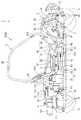
図8〜図11に示すように、吸気装置であるエアクリーナ110は、助手席10の後方、且つ内燃機関13の右側方に配置されており、第1エアクリーナ室111と第2エアクリーナ室112とを備える。 As shown in FIGS. 8 to 11, the
第1エアクリーナ室111には、助手席10の後方に配置され、開口を覆うカバー114を備えたシュノーケル113が、その車幅方向外側面に取り付けられたシュノーケルダクト170を介して接続される。第1エアクリーナ室111と第2エアクリーナ室112は、リヤ起立フレーム76の一部を跨ぐようにして車幅方向に対向しており、接続チューブ116によって連通される。また、第2エアクリーナ室112は、コネクティングチューブ117によって内燃機関13に接続される。 A
これにより、第1エアクリーナ室111がリヤ起立フレーム76の車幅方向外側に配置され、第2エアクリーナ室112がリヤ起立フレーム76の車幅方向内側に配置される。 As a result, the first air
具体的に、図11に示すように、第1エアクリーナ室111は、第1のエアクリーナケース131と、第1のリッド132と、エアクリーナエレメント115と、から主に構成され、第2エアクリーナ室112は、第2のエアクリーナケース133と、第2のリッド134と、遮熱プレート135と、から主に構成される。 Specifically, as shown in FIG. 11, the first air
第1のエアクリーナケース131は、樹脂製であり、上方に開口しており、上縁部の前後方向対向位置に、エアクリーナステー136、及びリヤ起立フレーム76から延びるステー137(図9参照)がタッピングスクリュー138によって取り付けられるフレーム側支持部139を有すると共に、上縁部のコーナー部及び車幅方向対向位置にリッド固定用のフック140を有する。また、第1のエアクリーナケース131の車幅方向側面には、シュノーケルダクト170に接続されたシュノーケルチューブ171と、接続チューブ116と、をそれぞれ固定するための取付け孔(図示せず)を有する。さらに、第1のエアクリーナケース131は、底部に設けられたドレイン孔141にドレインホース142を接続しており、ドレインホース142はホースバンド143によって固定される。 The first
第1のリッド132は、第1のエアクリーナケース131の上方開口部を覆う板状に形成されており、コーナー部及び車幅方向対向位置に係止部144を有する。第1のリッド132は、第1のエアクリーナケース131の上縁部との間にシール部材145を挟み込んだうえで、6個のバインダ146が、一方で第1のエアクリーナケース131のフック140に他方で第1のリッド132の係止部144に、それぞれ係止されることで第1のエアクリーナケース131に組み付けられる。 The
エアクリーナエレメント115は、円筒状で端部が閉塞されたエレメント本体147と、円筒状のボディ148と、を有する。このエレメント115は、ボディ148にエレメント本体147が組み付けられた状態で、第1のエアクリーナケース131内において、接続チューブ116に差し込まれ、接続チューブ116にホースバンド149が外嵌されることで、内部が接続チューブ116内に接続されて第1のエアクリーナケース131に組み付けられる。エレメント115は、第1のエアクリーナケース131内に導入された空気中の塵埃を除去し、浄化された空気を接続チューブ116を通じて第2エアクリーナ室112に供給する。 The
第2のエアクリーナケース133も、樹脂製で、上方に開口しており、第1のエアクリーナケース131より高い位置に配置されている。また、第2のエアクリーナケース133は、上縁部の後方位置にリヤアッパフレーム75から延びるステー(図示せず)がタッピングスクリュー150によって取り付けられるフレーム側支持部151を有すると共に、上縁部のコーナー部及び車幅方向対向位置にリッド固定用のフランジ152を有する。また、第1のエアクリーナケース131の車幅方向側面には、接続チューブ116とコネクティングチューブ117を固定するための取付け孔153(一方のみ図示)を有する。さらに、第2のエアクリーナケース133の底部には、ホースクリップ155,155によって固定されるブリーザホース154が接続されるとともに、一端がプラグ156によって閉じられ、ホースクランプ157,157によって固定されるドレインチューブ158が接続される。 The second
第2のリッド134は、第2のエアクリーナケース133の上方開口部を覆う板状に形成されており、コーナー部及び車幅方向対向位置に取付け孔159を有する。第2のリッド134は、第2のエアクリーナケース133の上端部との間にシール部材160を挟み込んだうえで、5個のタッピングスクリュー161を、第2のリッド132の取付け孔159から第2のエアクリーナケース133のフランジ152に螺合させることで第2のエアクリーナケース133に組み付けられる。なお、図中、162は、第2のエアクリーナケース133内に配置されるダストカバーである。 The
コネクティングチューブ117は、ゴム等の弾性部材によって筒状に形成されており、一端部が第2のエアクリーナケース133の取付け孔153に内嵌され、他端部がスロットルバルブユニット19(図8参照)に結合された状態で、ホースバンド163が外嵌されることで第2エアクリーナ室112をスロットルバルブユニット19に接続する。 The connecting
第1エアクリーナ室111とシュノーケルダクト170との間には、ゴム等の弾性部材によって筒状に形成されたシュノーケルチューブ171が設けられており、このシュノーケルチューブ171の一端部は第1のエアクリーナケース131の取付け孔に内嵌され、他端部がシュノーケルダクト170に結合された状態でホースバンド172が外嵌されることで、第1エアクリーナ室111をシュノーケルダクト170に接続する。なお、シュノーケル113のカバー114は、シュノーケルガード173内に配置されており、シュノーケルダクト170は、ステー174を介してサイドフレーム51の後立上り部51bに取り付けられる。 A
このようなエアクリーナ110は、シュノーケル113から外部空気を導入し、第1エアクリーナ室111のエアクリーナエレメント115によって空気中の塵埃が除去され、接続チューブ116を通って第2エアクリーナ室112に導かれた後、コネクティングチューブ117から浄化された空気が内燃機関13へ供給される。 After
エアクリーナ110は、ロアフレーム34の車幅方向外側に配置された第1エアクリーナ室111と、車幅方向内側に配置された第2エアクリーナ室112とを備えるので、フレームで囲まれた狭い空間内に、大きな容量のエアクリーナ110をコンパクトに配置することができる。また、第1エアクリーナ室111がリヤ起立フレーム76の車幅方向外側に配置されているので、エアクリーナ110のメンテナンススペースが広くなり、メンテナンス作業を容易に行うことができ、整備性に優れる。
なお、第1エアクリーナ室111と第2エアクリーナ室112は、取付位置に応じて、リヤ起立フレーム76の他、ロアフレーム34やリヤアッパフレーム75の一部を跨ぐように配置される場合にも、上記効果を奏する。Since the
Note that the first air
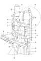
また、図8及び図12に示すように、シリンダヘッド18の前部に接続された排気管120は、前方に向かって延びた後、Uターンして後方に向かって延び、さらに略90°で屈曲し、水平面に対して下方に傾斜しながら直線的に車体外方に向かって延びる。さらに、排気管120は、車幅方向で運転席9の後方領域に達した後、車体内方に屈曲して上方に傾斜しながら直線的に略車体中心線CL上に戻り、リヤフレーム部4の略車体中心線CL上に前後方向に向けて配設された消音器122に接続している。これにより、排気管120の最外方延出部121は、サイドフレーム51の後方延長線上より車幅方向内側、且つリヤアッパフレーム75より車幅方向外側まで延出している。 Further, as shown in FIGS. 8 and 12, the
従って、内燃機関13が乗員用シート11後方に配置されて、リヤフレーム部4のスペースが制約された、例えば低床化された車両1においても、排気管120の長さを必要長さだけ確保することができる。また、排気管120の直線部分が多いので、加工が容易であり、組立て工数を低減して制作費を抑制することができる。 Therefore, the
排気管120の最外方延出部121は、サイドフレーム51の後方延長線上より車幅方向内側、且つリヤアッパフレーム75より車幅方向外側まで延出している。これにより、排気管120の長さを確保しつつ、排気管120が保護される。 The outermost extending
また、排気管120は、リヤ起立フレーム76の前方で略車体中心線CL上に戻るので、リヤ起立フレーム76より後方に配設された後輪用懸架装置との干渉が確実に防止される。 Further, since the
以上説明したように、本実施形態に係る車両の吸気装置によれば、エアクリーナ110は、第1エアクリーナ室111と第2エアクリーナ室112とから構成され、第1エアクリーナ室111および第2エアクリーナ室112が、車体フレーム30の一部を跨ぐように配置されているので、車体フレーム30で囲まれた空間が狭い場合でも、必要とされる所定容量が確保されたエアクリーナ110をコンパクトに配置することができる。 As described above, according to the vehicle intake device of this embodiment, the
また、エアクリーナ110は、運転席9または助手席10の後方、且つリヤフレーム部4の略車体中心線CL上に位置する内燃機関13の側方に配置されており、第1エアクリーナ室111および第2エアクリーナ室112が、ロアフレーム34、リヤアッパフレーム75、またはリヤ起立フレーム76の一部を車幅方向に跨いで配置されているので、低床化、コンパクト化されてスペースが制限されたリヤフレーム部4に、エアクリーナ110をコンパクトに配置して、必要とされる所定容量を確保することができる。 The
さらに、ロアフレーム34、リヤアッパフレーム75またはリヤ起立フレーム76の車幅方向外側に配置された第1エアクリーナ室111にエアクリーナエレメント115が配置されているので、エアクリーナ110のメンテナンススペースを広くとることができ、良好な整備性が確保される。また、第2エアクリーナ室112がロアフレーム34、リヤアッパフレーム75、またはリヤ起立フレーム76の車幅方向内側に配置されているので、第1エアクリーナ室111とともに必要とされる所定容量を確保することができる。 Further, since the
尚、本発明は、前述した実施形態に限定されるものではなく、適宜、変形、改良等が可能である。例えば、本発明においては、MUV(マルチ・ユーティリティ・ビークル)に適用したものとして説明したが、これに限定されるものではなく、4輪以上の車輪を有する任意の形式の車両にも同様に適用することができる。 In addition, this invention is not limited to embodiment mentioned above, A deformation | transformation, improvement, etc. are possible suitably. For example, although the present invention has been described as applied to an MUV (multi-utility vehicle), the present invention is not limited to this, and is similarly applied to any type of vehicle having four or more wheels. can do.
1 車両
2 フロントフレーム部
3 センタフレーム部
4 リヤフレーム部
9 運転席
10 助手席
11 乗員用シート
13 内燃機関
30 車体フレーム
31 フロントロアフレーム
32 センターロアフレーム
33 リヤロアフレーム
34 ロアフレーム
75 リヤアッパフレーム
76 リヤ起立フレーム
81 フロントディファレンシャルギヤユニット(前輪駆動系)
82 フロントドライブシャフト(前輪駆動系)
84 リヤディファレンシャルギヤユニット(後輪駆動系)
85 リヤドライブシャフト(後輪駆動系)
110 エアクリーナ
111 第1エアクリーナ室
112 第2エアクリーナ室
113 シュノーケル
114 開口部
115 エアクリーナエレメント
116 接続チューブ
117 コネクティングチューブ
CL 車体中心線DESCRIPTION OF
82 Front drive shaft (front wheel drive system)
84 Rear differential gear unit (rear wheel drive system)
85 Rear drive shaft (rear wheel drive system)
110
Claims (1)
Translated fromJapanese動力を発生する内燃機関と、
空気を浄化して前記内燃機関に供給するエアクリーナと、
を備える車両の吸気構造であって、
前記車体フレームは、前記車体の左右下部に配置されて前後方向に延びる一対のロアフレームと、前記ロアフレームの後端から上方に延びた後、前記内燃機関を覆うように屈曲して前方に延設される左右一対のリヤアッパフレームと、前記各リヤアッパフレームと前記各ロアフレームとをそれぞれ連結する一対のリヤ起立フレームと、を備え、
前記内燃機関は、前記乗員用シート後方の略車体中心線上に配置され、
前記エアクリーナは、空気中の塵埃を除去するエアクリーナエレメントを内蔵する第1エアクリーナ室と、前記内燃機関へ浄化された空気を供給する第2エアクリーナ室と、前記第1エアクリーナ室と前記第2エアクリーナ室とを連通させる接続チューブと、を備え、
前記第1エアクリーナ室が前記ロアフレーム、または前記リヤアッパフレーム、または前記リヤ起立フレームの車幅方向外側に位置すると共に、前記第2エアクリーナ室が前記ロアフレーム、または前記リヤアッパフレーム、または前記リヤ起立フレームの車幅方向内側に位置するように、前記第1エアクリーナ室および前記第2エアクリーナ室が、前記ロアフレーム、または前記リヤアッパフレーム、または前記リヤ起立フレームの一部を車幅方向に跨いで配置されることを特徴とする車両の吸気構造。A body frame and a pair of passenger seats arranged side by side in the vehicle width direction to form a driver seat and a passenger seat;
An internal combustion engine that generates power;
An air cleaner for purifying the air and supplying it to the internal combustion engine;
A vehicle intake structure comprising:
The vehicle body frame is disposed at the left and right lower portions of the vehicle body and extends in the front-rear direction, and extends upward from the rear end of the lower frame, and then bends and extends forward so as to cover the internal combustion engine. A pair of left and right rear upper frames provided, and a pair of rear standing frames that connect the respective rear upper frames and the respective lower frames,
The internal combustion engine is disposed on a substantially vehicle body center line behind the occupant seat,
The air cleaner includes a first air cleaner chambercontaining an air cleaner element for removing dustin the air, a second air cleaner chamberfor supplying purified air to the internal combustion engine,the first air cleaner chamber, and the second air cleaner chamber. A connecting tube that communicates with
The first air cleaner chamber is located outside the lower frame, the rear upper frame, or the rear standing frame in the vehicle width direction, and the second air cleaner chamber is the lower frame, the rear upper frame, or the rear The first air cleaner chamber and the second air cleaner chamber straddle the lower frame, the rear upper frame, or a part of the rear standing frame in the vehicle width direction so as to be located on the inner side in the vehicle width direction of the standing frame. intake structure for a vehicle, characterized inthat in the arrangement.
Priority Applications (3)
| Application Number | Priority Date | Filing Date | Title |
|---|---|---|---|
| JP2008253174AJP5206957B2 (en) | 2008-09-30 | 2008-09-30 | Vehicle intake structure |
| CA2673402ACA2673402C (en) | 2008-09-30 | 2009-07-21 | Intake structure of vehicle |
| US12/534,806US8251170B2 (en) | 2008-09-30 | 2009-08-03 | Intake structure of vehicle |
Applications Claiming Priority (1)
| Application Number | Priority Date | Filing Date | Title |
|---|---|---|---|
| JP2008253174AJP5206957B2 (en) | 2008-09-30 | 2008-09-30 | Vehicle intake structure |
Publications (2)
| Publication Number | Publication Date |
|---|---|
| JP2010083272A JP2010083272A (en) | 2010-04-15 |
| JP5206957B2true JP5206957B2 (en) | 2013-06-12 |
Family
ID=42056187
Family Applications (1)
| Application Number | Title | Priority Date | Filing Date |
|---|---|---|---|
| JP2008253174AExpired - Fee RelatedJP5206957B2 (en) | 2008-09-30 | 2008-09-30 | Vehicle intake structure |
Country Status (3)
| Country | Link |
|---|---|
| US (1) | US8251170B2 (en) |
| JP (1) | JP5206957B2 (en) |
| CA (1) | CA2673402C (en) |
Families Citing this family (23)
| Publication number | Priority date | Publication date | Assignee | Title |
|---|---|---|---|---|
| US8640814B2 (en)* | 2009-06-15 | 2014-02-04 | Polaris Industries Inc. | Side-by-side vehicle |
| JP5865224B2 (en) | 2012-09-27 | 2016-02-17 | 本田技研工業株式会社 | Four-wheeled vehicle |
| US8567847B1 (en) | 2013-02-06 | 2013-10-29 | Honda Motor Co., Ltd. | Vehicles having utility bed with flexible seal |
| US8998216B2 (en)* | 2013-02-14 | 2015-04-07 | Yamaha Hatsudoki Kabushiki Kaisha | Vehicle |
| US20140360794A1 (en)* | 2013-06-10 | 2014-12-11 | Kyle Tallman | Snorkel Apparatus and Method of Use for All-Terrain Vehicles |
| RU2637139C1 (en)* | 2014-01-31 | 2017-11-30 | Бомбардье Рекриэйшенел Продактс Инк. | Off-road vehicles with side by side seating |
| JP5847872B2 (en) | 2014-03-28 | 2016-01-27 | 本田技研工業株式会社 | Vehicle with winch |
| JP2016011023A (en)* | 2014-06-27 | 2016-01-21 | ヤマハ発動機株式会社 | vehicle |
| US10300786B2 (en)* | 2014-12-19 | 2019-05-28 | Polaris Industries Inc. | Utility vehicle |
| JP6512968B2 (en)* | 2015-07-02 | 2019-05-15 | 株式会社クボタ | Multipurpose work vehicle |
| US11391253B1 (en)* | 2015-08-17 | 2022-07-19 | Arctic Cat Inc. | Vehicle intake |
| US9683527B2 (en)* | 2015-11-09 | 2017-06-20 | Kyle Tallman | Snorkel apparatus with auxiliary air tube supports |
| CN110382856B (en)* | 2017-01-30 | 2021-07-27 | 庞巴迪动力产品公司 | Vehicle with air filter service panel |
| US11014419B2 (en) | 2017-03-21 | 2021-05-25 | Arctic Cat Inc. | Off-road utility vehicle |
| US10717474B2 (en) | 2017-03-21 | 2020-07-21 | Arctic Cat Inc. | Cab and fasteners for vehicle cab |
| US11046176B2 (en)* | 2017-03-21 | 2021-06-29 | Arctic Cat Inc. | Off-road utility vehicle |
| US10337474B1 (en)* | 2018-03-27 | 2019-07-02 | Honda Motor Co., Ltd. | Air intake system |
| US12187127B2 (en) | 2020-05-15 | 2025-01-07 | Polaris Industries Inc. | Off-road vehicle |
| JP7265504B2 (en)* | 2020-06-10 | 2023-04-26 | 株式会社クボタ | work machine |
| CA3156559A1 (en) | 2021-05-05 | 2022-11-05 | Polaris Industries Inc. | Exhaust assembly for a utility vehicle |
| MX2023006716A (en) | 2022-06-13 | 2023-12-14 | Polaris Inc | POWER TRAIN FOR UTILITY VEHICLE. |
| US12331705B2 (en)* | 2023-08-04 | 2025-06-17 | Kawasaki Motors, Ltd. | Off-road vehicle |
| CN119551128A (en)* | 2023-09-04 | 2025-03-04 | 浙江春风动力股份有限公司 | All Terrain Vehicles |
Family Cites Families (8)
| Publication number | Priority date | Publication date | Assignee | Title |
|---|---|---|---|---|
| JPS4984503U (en)* | 1972-11-13 | 1974-07-22 | ||
| US5860685A (en)* | 1997-05-08 | 1999-01-19 | Chrysler Corporation | Fresh air duct system for a vehicle |
| JP4040418B2 (en)* | 2002-09-30 | 2008-01-30 | 本田技研工業株式会社 | Air cleaner device for vehicle |
| US7287619B2 (en)* | 2003-04-02 | 2007-10-30 | Yamaha Hatsudoki Kabushiki Kaisha | Air intake system for off-road vehicle |
| US7438147B2 (en)* | 2003-04-02 | 2008-10-21 | Yamaha Hatsudoki Kabushiki Kaisha | Transmission for off-road vehicle |
| JP4467054B2 (en)* | 2004-09-30 | 2010-05-26 | 本田技研工業株式会社 | Vehicle body frame structure |
| US20080083575A1 (en)* | 2006-04-07 | 2008-04-10 | Messerschmitt Design Ltd. | External air scoop for internal combustion engine air intake of an automobile |
| US7819220B2 (en)* | 2006-07-28 | 2010-10-26 | Polaris Industries Inc. | Side-by-side ATV |
- 2008
- 2008-09-30JPJP2008253174Apatent/JP5206957B2/ennot_activeExpired - Fee Related
- 2009
- 2009-07-21CACA2673402Apatent/CA2673402C/ennot_activeExpired - Fee Related
- 2009-08-03USUS12/534,806patent/US8251170B2/ennot_activeExpired - Fee Related
Also Published As
| Publication number | Publication date |
|---|---|
| JP2010083272A (en) | 2010-04-15 |
| US8251170B2 (en) | 2012-08-28 |
| US20100078240A1 (en) | 2010-04-01 |
| CA2673402C (en) | 2012-01-17 |
| CA2673402A1 (en) | 2010-03-30 |
Similar Documents
| Publication | Publication Date | Title |
|---|---|---|
| JP5206957B2 (en) | Vehicle intake structure | |
| JP4965537B2 (en) | Body structure | |
| JP5093506B2 (en) | Vehicle frame structure | |
| JP5317617B2 (en) | Vehicle exhaust pipe structure | |
| JP5879346B2 (en) | Saddle riding vehicle | |
| US7730986B2 (en) | Electric component arrangement structure for vehicle, vehicle having the same, and method for arranging electric component in vehicle | |
| JP4649358B2 (en) | Air intake structure for seat type vehicles | |
| JP2011196314A (en) | Air cleaner device | |
| JP5129632B2 (en) | Harness holding structure for saddle-ride type vehicles | |
| TW201144126A (en) | Vehicle | |
| JP2009012609A (en) | Tractor power structure | |
| CA2566946C (en) | Front structure for vehicle | |
| JP5323602B2 (en) | Vehicle transmission member routing structure | |
| TW200404695A (en) | Scooter-type vehicle | |
| CN207311094U (en) | Work vehicle | |
| JPWO2011117919A1 (en) | Arrangement structure of intake system of saddle-ride type vehicle | |
| JP4367879B2 (en) | Air cleaner for vehicle | |
| JP6270893B2 (en) | Motorcycle | |
| TW585966B (en) | Secondary air supply system of motorcycle | |
| JP2023047999A (en) | saddle-riding vehicle | |
| WO2025074647A1 (en) | Leaning vehicle | |
| TWI248893B (en) | Floor structure of motorcycles | |
| JP2010047030A (en) | Motorcycle |
Legal Events
| Date | Code | Title | Description |
|---|---|---|---|
| A621 | Written request for application examination | Free format text:JAPANESE INTERMEDIATE CODE: A621 Effective date:20101126 | |
| A977 | Report on retrieval | Free format text:JAPANESE INTERMEDIATE CODE: A971007 Effective date:20120531 | |
| A131 | Notification of reasons for refusal | Free format text:JAPANESE INTERMEDIATE CODE: A131 Effective date:20120605 | |
| A521 | Written amendment | Free format text:JAPANESE INTERMEDIATE CODE: A523 Effective date:20120803 | |
| RD03 | Notification of appointment of power of attorney | Free format text:JAPANESE INTERMEDIATE CODE: A7423 Effective date:20120803 | |
| RD04 | Notification of resignation of power of attorney | Free format text:JAPANESE INTERMEDIATE CODE: A7424 Effective date:20120806 | |
| TRDD | Decision of grant or rejection written | ||
| A01 | Written decision to grant a patent or to grant a registration (utility model) | Free format text:JAPANESE INTERMEDIATE CODE: A01 Effective date:20130122 | |
| A61 | First payment of annual fees (during grant procedure) | Free format text:JAPANESE INTERMEDIATE CODE: A61 Effective date:20130205 | |
| FPAY | Renewal fee payment (event date is renewal date of database) | Free format text:PAYMENT UNTIL: 20160301 Year of fee payment:3 | |
| R150 | Certificate of patent or registration of utility model | Ref document number:5206957 Country of ref document:JP Free format text:JAPANESE INTERMEDIATE CODE: R150 Free format text:JAPANESE INTERMEDIATE CODE: R150 | |
| LAPS | Cancellation because of no payment of annual fees |